Embed Size (px)
Citation preview
ELSEVIER Signal Processing 36 (1994) 163-174
SIGNAL PROCESSING
FIR approximations of inverse filters and perfect reconstruction filter banks
Michael Unser,*' t Murray Eden
Biomedical Engineering and Instrumentation Program, Bldg 13, Room 3 W13, National Center for Research Resources, National Institutes of Health, Bethesda, MD 20892, USA
Received 31 October 1991; revised 24 February 1992, 16 July 1992 and 30 November 1992
Abstract
This paper first describes an algorithm that finds the approximate finite impulse response (FIR) inverse of an FIR filter by minimizing the inversion (or reconstruction) error constrained to zero-bias. The generalization of the inverse filtering problem in the two channel case is the design of perfect reconstruction filter banks that use critical sampling. These considerations lead to the derivation of an algorithm that provides a minimum error and unbiased F IR /FIR approxima- tion of a perfect reconstruction I IR/FIR (or FIR/IIR) filter bank. The one-channel algorithm is illustrated with the design of an FIR filter to compute the B-spline coefficients for cubic spline signal interpolation. The two-channel algorithm is applied to the design of a F IR /FIR filter bank that implements the cubic B-spline wavelet transform. Finally, we consider a modification of this technique for the design of modulated-filter banks, which are better suited for subband coding.
Zusammenfassung
Dieser Artikel beschreibt zunfichst einen Algorithmus, der n/iherungsweise die FIR-Inverse eines FIR-Filters durch Minimierung des Inversions- (oder Rekonstruktions-) Fehlers unter der Nebenbedingung eines verschwindenden mittleren Fehlers (Bias) findet. Die Verallgemeinerung des inversen Filterproblems im Zweikanal-Fall ist der Entwurf einer Filterbank mit perfekter Rekonstruktion, die kritische Abtastung ben/itzt. Diese Oberlegungen ftihren zur Ableitung eines Algorithmus, der einen minimalen Fehler und eine biasfreie F IR/FIR N/iherung einer perfekten I IR/FIR (oder FIR/IIR) Rekonstruktionsfilterbank liefert. Der Einkanal-Algorithmus wird mit dem Entwurf eines FIR-Filters veranschaulicht, um die B-Spline Koeffizienten fiir die kubische Spline-Signalinterpolation zu berechnen. Der Zweikanal-Algorithmus wird zum Entwurf einer F IR/FIR Filterbank, die die kubische B-Spline Wavelet-Transforma- tion implementiert, angewendet. Zum SchluB wird eine Modifikation dieser Technik f/Jr den Entwurf von modulierten Filterb/inken betrachtet, die besser geeignet sind f/ir Teilband-Codierung.
R~um~
Nous pr~sentons d 'abord un algorithme qui calcule une approximation fi r~ponse impulsionnelle finie (FIR) de l'inverse d'un filtre FIR. Cette m6thode se base sur la minimisation de l'erreur de reconstruction sous la contrainte d'un
* Corresponding author. Email: [email protected] t On leave from INSERM U. 2, H6pital Henri-Mondor, F-94010 Cr&eil, France.
Elsevier Science B.V. SSDI 0165-1684(93)E0083-W
164 M. Unser, M. Eden / Signal Processing 36 (1994) 163-174
biais nul. La grnrralisation du problrme d'inversion pour deux canaux est la synthrse de bancs de filtres ~t reconstruction parfaite. Ceci mrne 5. la description d'un algorithme pour la determination d'une approximation FIR/FIR aux moindres carrrs d'un banc de filtres IIR/FIR (ou FIR/IIR) h reconstruction parfaite. Le premier algorithme est illustr6 avec la synthrse d'un filtre FIR permettant le calcul directe des coefficients B-splines pour une interpolation du signal par splines cubiques. Le second algorithme est appliqu6 ~ la synthrse d'un banc de filtres FIR/FIR permettant le calcul rapide de la transformation d'ondelettes de type B-spline cubique. Finalement, nous prrsentons une variation de cette mrthode pour la synthrse de banc de filtres modulrs qui sont plus approprirs pour le codage en sous-bandes.
Keywords: Least-squares design; Inverse filter; Perfect reconstruction filler bank; Wavelet transform; Spline functions; Cubic splines; B-splines; Gabor transform; Interpolation
1. Introduction
There are many signal transformations that can be formulated in terms of shift-invariant convolu- tion operators. It is often of interest to perform, or at least approximate, the inverse transformation. This task involves the design of inverse or pseudo- inverse filters. In the one-channel case, this problem is equivalent to designing a deconvolution filter, which is especially relevant for signal restoration. When the initial operator has a finite impulse re- sponse (FIR), the inverse filter that allows signal recovery is generally recursive which may lead to instabilities and limit cycles. To avoid such prob- lems, Gfilboy and Geqkinli [9] have proposed us- ing an FIR filter approximation derived from the optimization of a least-squares criterion; a similar algorithm has also been described in [17]. The use of inverse filters can also be useful in other applica- tions, for example, polynomial spline interpolation for which this technique provides an efficient way to solve the system of banded equations that deter- mine the B-spline coefficients [21].
In the two (or more) channel case, this basic inversion problem is closely related to the design of multirate filter banks that permit perfect recon- struction [24, 26]. An example of a system that uses critical sampling and allows perfect signal recovery is the quadrature mirror filter (QMF) bank [3, 24]. Such filter banks can be applied hierarchically to produce subband signal decompositions. The ap- plication of this concept to image coding has led to very promising results [1, 19, 25,28]. More re- cently, Mallat showed that the same computational technique could be used to implement the wavelet transform [12, 13]. This latter representation is the expansion of a signal in terms of hierarchical basis
functions obtained by translation and dilation of a single template: the wavelet function [4, 13, 14].
In this paper, we investigate the special case in which the transformations to be inverted involve given FIR filters. One practical problem in this situation is that the corresponding inverse oper- ators generally have an infinite impulse response (IIR). Our approach is to use instead a truncated FIR approximation with a prescribed error toler- ance. For this purpose, we apply a general design principle based on the minimization of the recon- struction error. One variation of this procedure is a constrained optimization that demands perfect reconstruction of the DC signal component (zero- bias constraint). In the one-channel case, this for- mulation yields a matrix algorithm for the FIR approximation of an all-pole filter. In the two- channel case, it results in a least-squares design technique for perfect reconstruction filter banks; this procedure is applicable whenever the analysis (or synthesis) filters are certain specified FIR ker- nels. This direct method provides an alternative to the iterative LMS-based algorithm recently pro- posed by Paillard et al. [15]; it also offers the flexibility of adding constraints to the system. The same computational techniques may also be useful in designing fast algorithms for the determination of the expansion coefficients of a continuous signal representation in terms of shifted basis functions of compact support. Such representations are fre- quently used for signal interpolation [10, 16, 21]; they occur as well in the context of the wavelet transform [22, 27].
The presentation is organized as follows. Sec- tion 2 provides a precise statement of the perfect reconstruction (PR) problem in the one-channel (inverse filter) and two-channel case. Section 3 is

M. Unser, M. Eden / Signal Processing 36 (1994) 163-174 165
concerned with the derivation of a constrained least-squares procedure for designing an FIR filter to approximate the inverse of a given convolution kernel. Section 4 extends this technique to the two- channel case and presents a general design tech- nique for a minimum reconstruction error FIR/FIR filter bank. Section 5 presents a few ex- perimental examples and compares the proposed approaches with a reference technique that uses simple truncation of the theoretical impulse re- sponses. The one-channel algorithm is applied to the design of an inverse filter for efficient implemen- tation of the direct cubic spline transform [21], The two-channel algorithm is illustrated with the design of a fast algorithm for the cubic B-spline wavelet transform [2, 23]. It is worth noting that the corres- ponding decomposition provides a reversible multiresolution signal analysis that is close to opti- mal in terms of its time/frequency localization [22]. This representation is in many respects similar to a hierarchical or wavelet-like Gabor transform [5-7].
1.1. Notations and operators
A signal {a(k)}k~Z is characterized by its z-trans- form, which we denote by a capital letter
+oo A(z) = k=~ oo a(k )z-k" (1.1)
This zcorrespondence is also expressed as: a(k) , , A(z). The unit impulse at k = i is repres- ented by the symbol
1, k = i, ~ z_i. hi(k) = 0, otherwise, (1.2)
The down-sampling (or decimation) by a factor of two is defined by
[a]J,2(k) = a(2k) ~ z , l(A(zl/2) + A(-- zl/2)).
(1.3)
The complementary operation is the up-sampling by a factor of two
~a(k/2), k even, z , A(z2). (1.4) [a]r2(k) = [0 , k odd, '
Fig. 1. Block diagram for the inverse filtering problem
2. Statement of the problem
2.1. Inverse filter
Let us consider the block diagram in Fig. 1, where the convolution operator 9 is an FIR filter of length M = k2 - kl + 1:
k2 9 ( k ) , z , G(z)= ~ 9(k)z -k. (2.1)
k = k 1
We seek an operator h that compensates exactly for the effect of g. This leads to the constraint:
V k e Z , h*g(k) = 6o(k), (2.2)
where 6o(k ) is the unit impulse at the origin (cf. (1.2)). A filter satisfying (2.3) is referred to as the inverse filter of # and is characterized by
h(k) = (9)-~(k) ~ z , H(z) = 1/G(z). (2.3)
The operator is stable provided that the complex roots of G(z) are not on the unit circle. In general the inverse filter has an IIR. In Section 3, we will consider the problem of finding an FIR approxima- tion of (O)-~ that satisfies (2.2) in the least-square sense.
2.2. IIR/FIR perfect reconstruction filter banks
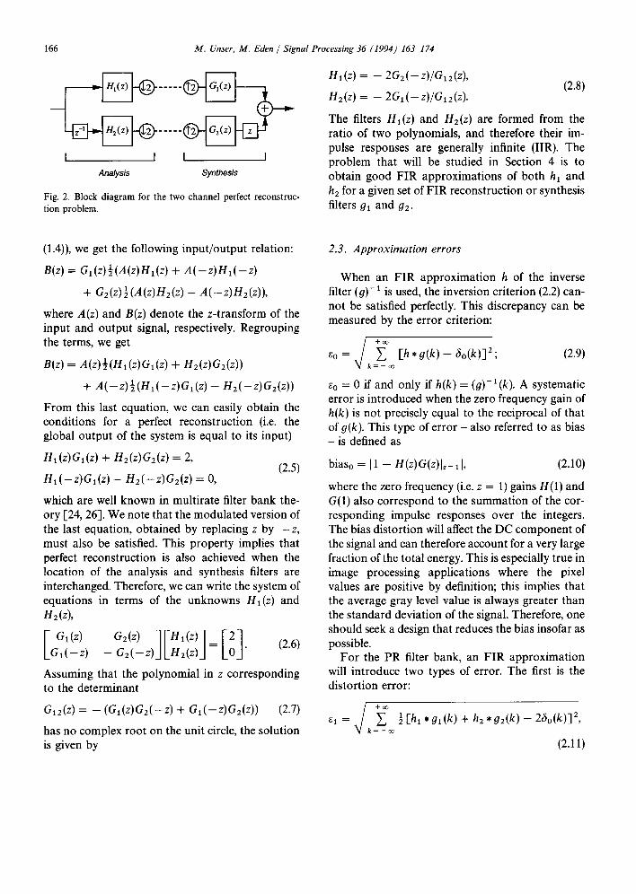
Fig. 2 represents the block diagram of a standard two-channel PR filter bank. Note that two delays have been included in the definition of the filters in the lower branch in order to simplify some of the notation. Here, we will consider the special situ- ation in which the reconstruction (or synthesis) filters are two FIR filters given a priori:
k2~ gi(k) ~ z ' Gi(z)= ~ gi(k)z -k, i = 1, 2. (2.4)
k = kl~
By expressing the effect of down-sampling and up- sampling in the z-transform domain (cf. (1.3) and
1 6 6 M. Unser, M. Eden / Signal Processing 36 (1994) 163-174
I I I I Analysis Synthesis
Fig. 2. Block diagram for the two channel perfect reconstruc- tion problem.
H1 (z) = - - 2G2 ( - - z ) / G l 2 (z),
1-12 (z) = -- 2C,1 ( - - z) /C, , 2 (z). (2.8)
The filters Hi(z) and H 2 ( z ) a r e formed from the ratio of two polynomials, and therefore their im- pulse responses are generally infinite (IIR). The problem that will be studied in Section 4 is to obtain good FIR approximations of both hi and h2 for a given set of FIR reconstruction or synthesis filters 91 and g2.
(1.4)), we get the following input/output relation:
B(z) = al(z)½(A(z)Hl(z) + A ( - z ) H l ( - Z )
+ Gz(z)½(a(z)Hz(z) - A(-z)Hz(z)),
where A(z) and B(z) denote the z-transform of the input and output signal, respectively. Regrouping the terms, we get
B(z) = a(z)½(Hl(Z)Gx(z) + H2(z)G2(z))
+ A( - z )½(Hx( - z )G, ( z ) - H2(-z)G2(z))
From this last equation, we can easily obtain the conditions for a perfect reconstruction (i.e. the global output of the system is equal to its input)
H1 (z) G1 (z) + H2 (z) G2 (z) = 2, (2.5)
Hl(-z)Gl(z) - H 2 ( - z ) G 2 ( 2 ) = 0 ,
which are well known in multirate filter bank the- ory [24, 26]. We note that the modulated version of the last equation, obtained by replacing z by - z , must also be satisfied. This property implies that perfect reconstruction is also achieved when the location of the analysis and synthesis filters are interchanged. Therefore, we can write the system of equations in terms of the unknowns Hi(z) and nz(z),
[ G,(z) G2(z )1VHl ( z ) l=[201" (2.6) Gl(-Z) - Gi(--z)JLHB(z)J
Assuming that the polynomial in z corresponding to the determinant
G,2(z) = - (G,(z)Gz(-Z) + Gl(-Z)G2(z)) (2.7)
has no complex root on the unit circle, the solution is given by
2.3. Approximation errors
When an FIR approximation h of the inverse filter (g)- 1 is used, the inversion criterion (2.2) can- not be satisfied perfectly. This discrepancy can be measured by the error criterion:
So = , / ~o~ [h* g(k) - 6o(k)]2; (2.9) ~/ k = - m
e0 = 0 if and only if h(k) = (O)-l(k). A systematic error is introduced when the zero frequency gain of h(k) is not precisely equal to the reciprocal of that of o(k). This type of error - also referred to as bias - is defined as
biaso = I1 - H(z)G(z)lz= 11, (2.10)
where the zero frequency (i.e. z = 1) gains H(1) and G(1) also correspond to the summation of the cor- responding impulse responses over the integers. The bias distortion will affect the DC component of the signal and can therefore account for a very large fraction of the total energy. This is especially true in image processing applications where the pixel values are positive by definition; this implies that the average gray level value is always greater than the standard deviation of the signal. Therefore, one should seek a design that reduces the bias insofar as possible.
For the PR filter bank, an FIR approximation will introduce two types of error. The first is the distortion error:
e, = , / ~oo ½[h, *g,(k) + hE*g2(k)- 26o(k)] 2, ~/ k = - m
(2.11)
M . Unser, M . E d e n / S igna l P r o c e s s i n g 3 6 ( 1 9 9 4 ) 1 6 3 - 1 7 4 1 6 7
which expresses the fact that the global system response is not precisely an identity. The second is the aliasing error introduced by the sampling process:
/+Z° ~ l k = - ov
where the notation ~(k) = ( -1)kg(k) refers to the modulation of a signal. We note that the PR constraints (2.6) are equivalent to specifying an undistorted (e~ = 0) and alias-free reconstruction (~2 = 0).
In most cases, the upper branch of the filter bank in Fig. 2 corresponds to a lowpass filter, while the lower one performs as a highpass filter. It is there- fore also useful to measure the bias that affects the global system. Assuming G2(1)= 0, the bias is given by
bias1 = I1 - H i (z)Gl(z)l~= 11.
The design techniques presented next are based on the constrained minimization of these error criteria.
multipliers, we introduce the following criterion:
+ o o
L(h( l~) . . . . . h(/2),2) = ~ ( 6 0 ( k ) - h * g ( k ) ) 2 k = - oo
(' ) +2 ,~ 2 h ( l ) - ~ . (3.2) l = l l
Using the fact that h * g ( k ) = ~ l ~ _ l h ( 1 ) g ( k - l )
is a sequence of length K = M ~ - - ~ - 1 which is defined (i.e. not equal to zero) for k = kl + l~ . . . . . k2 + 12, this criterion is rewritten in matrix form as
L(h, 2) = (Gh - e)'(Gh - e) - 22(h'1 - e), (3.3)
where G = [g~] is the K x N convolution matrix
g i i = g ( k l + i - J ) , i = 1 . . . . . K , j = 1 . . . . . N ,
(3.4)
e = [e~] is the K-dimensional unit vector
e~=6o(k~ + 1 1 - 1 + i ) , i = 1 . . . . . K (3.5)
and h = [hj] the N-dimensional vector of unknown filter coefficients:
3. Inverse filter design
Let {g(k), k = k~ . . . . . k 2 } be an FIR filter of length M = k 2 - k~ + 1. The problem is to find an approximation of its inverse in terms of an FIR filter {h(l), 1= ll . . . . . / 2 } of length N = 12 - -
11 + 1. The approach suggested by Giilboy and Geqkinli is to minimize a mean square error cri- terion equivalent to e 2 [9]. These authors propose a design method relying on matrix algebra for the particular case where N = M.
Here, we will extend their technique in two re- spects. First, we will allow any given value of N, except that k~ + l~ ~< 0 and k 2 q- 12 >1 0 (these two bounds define the beginning and end points of the sequence h , g _-__ 60, respectively). Second, we will impose an additional constraint on the impulse response of the approximation:
h(l) = 1 ~ g(k) = c~, (3.1) 1 = ll k = kl
which, at least, guarantees exact inversion for a constant signal (i.e. biaso = 0). Using Lagrange
h j = h ( l ~ - I + j) , j = 1 , . . . , N . (3.6)
1 = [1 ... 1]' an N-dimensional vector of ones; the symbol ' denotes the transpose operator. The opti- mum filter coefficients are obtained by setting the derivative of (3.3) with respect to h to zero, which using standard rules of matrix differentiation [8], yields
(?L - - = 2 G ' G h - 2G 'e - 221 = 0. Oh
It follows that the general solution can be expressed a s
h = u + 2v, (3.7)
where
u = ( G ' G ) - I G ' e , (3.8)
v = (G' G ) - I 1, (3.9)
and where 2 is chosen to satisfy (3.1), i.e.
O ~ - l t u
2 - 1 ' ~ (3.10)

168 M. Unser, M. Eden / Signal Processing 36 (1994) 163-174
We note that u provides the unconstrained least- squares solution and is comparable to the solution found by Gfilboy and Geqkinli [9]. The correction term v is used to impose the constraint of a nor- malized impulse response.
4. Design of FIR pseudo-inverse filter banks
Let {0~(k), k = k~i . . . . ,k2i}, i = 1, 2 be two given FIR filters of length M~ and M2, respectively. The problem is to find the FIR approximations {hi(1),
l = ll i . . . . . 121}, i = 1, 2 of length N1 and N2 of the analysis filters on the left-hand side of the block diagram in Fig. 2. We also impose a constraint on the lowpass branch of the filter bank:
~" h ~ ( 1 ) - - 2 ~, fix(k) -- c~. I = 111 k = k .
(4.1)
We will solve this problem, which is a generaliz- ation of the previous one, by minimizing the total error criterion e 2 + e 2 (cf. Eqs. (2.11) and (2.12)) subject to the constraint (4.1). We note that the same procedure is also applicable when the role of the analysis and synthesis filters are interchanged. Using Lagrange multipliers, we introduce the func- tional
L(hx, /12, 2)
= ½(Glhl + G 2 h 2 - e)'(Glhl + G2h2 - e)
+ ½ ( G l h l - - G2h2) t ( l ~ l h l - G2h2)
- 2 ( l ' h 1 - ~ ) , (4.2)
where the first and second quadratic terms are precisely el 2 and e 2. In this notation, hi = [hsx] and h 2 = Ehj21 are the unknown N1- and N2-dimen- sional filter coefficient vectors:
h j i = h i ( l l l - l + j ) ; j = 1 . . . . . Ni , i = 1,2, (4.3)
with N1 = 121 - 111 - 1 and N2 =/22 - 112 - 1. 1 is an Nl-dimensional vector of ones and e -- [el] is a K-dimensional vector defined by
e i = 2 6 o ( i o - 1 + i ) , i = l . . . . . K, (4.4)
where i0 = min{kll + 111, k12 ÷ 112} and where
K = max{k21 +/21, k22 ÷ 122}
- min{k11 +/11,k12 +/12} + 1. (4.5)
The convolution matrices G1 = [Oisx ], G1 = [glsl ], G2 = [0ii2] and (~2 = [Ois2] are of size K x N1, K × N~, K x N 2 and K x N2, respectively. They are defined as
gilk = ok(ik + i - - j ) ,
i = 1 . . . . . K ; j = 1 . . . . . NR, k = 1,2, (4.6)
gijk : ( - - 1) ik + i -Jgk( ik ÷ i - - j ) ,
i = 1 . . . . . K ; j = 1 . . . . . NR, k = 1,2, (4.7)
where the offset constants il and i2 are given by
ik = min{k11 + 111, k12 ÷ / 1 2 } - - llk, k = 1, 2.
The minimization of (4.2) with respect to hi and h 2 yields the system of equations:
[ � ] h2 LG'~eJ ÷ 2 , (4.8)
where the 2K x (NI + N2) matrix [W] is defined as
+¢;¢1 [w] := LG, G, _ 0~, , G~G~ + t~0~_l" (4.9)
This system is solved by inverting [ W]. The gen- eral solution can be expressed as
= + 2 , (4.10) h2 u2 LU2J
where
us := [W]-lLGieJ and
[1ol, := [ W ] - I (4.11) F2
and where 2 is chosen to satisfy the zero-bias con- straint (4.1):
2 c t - l'Ul 2 = (4.12)
l 'V 1
As before, we note that the solution (4.10) is ex- pressed as the sum of two terms in which the first represents the unconstrained least-squares solution

M. Unser, M. Eden / Signal Processing36 (1994) 163-174 169
(ul and U2) , and the second is a correction term used to impose the constraint of a normalized im- pulse response.
5. Results
In this section, we apply the design methods described above to the problems of cubic spline interpolation [10, 21], and the decomposition of a signal using the cubic spline wavelet transform [2, 22]. We also compare the efficiency of these techniques to the standard design method that uses a truncation of the theoretical impulse responses. A tutorial overview of polynomial spline repres- entations in general, and a discussion of their rel- evance to signal processing can be found in [20]. Finally, we briefly discuss a slight variation of our procedure for the design of modulated filter banks which are better suited for subband coding.
5.1. Cubic spline transform
The cubic spline interpolation of a signal f (k) can be expressed as a weighted sum of cubic B-spline coefficients [18, 21]:
+oo
f ( x ) = ~ c(k)qg(x- k), (5.1) k = - o o
where ~o(x) is Schoenberg's cubic B-spline function
~(x) = #3(x) :=
2/3 -- x 2 + Ixl3/2, 0 ~ Ixl < 1,
(2 - Ix l )3 /6 , 1 ~ Ixl < 2,
0, 2 ~< [xl.
(5.2)
Bothf(x) and ~o(x) are continuous piecewise cubic functions with continuous first- and second-order derivatives (polynomial splines of order n = 3). In [21], it was shown that the cubic spline interpola- tion problem could be solved by direct B-spline filtering:
c(k) = (b3) - ' , f ( k ) , (5.3)
where (b~)-1 is the convolution inverse of a sam- pled cubic spline kernel (indirect B-spline filter):
b3(k):=fl3(x)b,= k , z , B3(z ) = z + 4 + z - ' 6
(5.4)
We have approximated the IIR filter (b3) -1 by a series of symmetrical FIR filters of increasing length using the different design techniques. The corresponding reconstruction errors and biases in percent ({ 100 × eo, 100 × biaso }) are given in Table 1. The standard technique is to simply truncate the impulse response; the impulse response is com- puted numerically by sampling the theoretical fre- quency response (1/B3(eJ2'ff)) and using a 64-point inverse FFT. As expected, the unconstrained least- squares solution (2 = 0) gives rise to the smallest reconstruction error. The bias as well is signifi- cantly reduced when compared to the truncated impulse response design (TIRD). The constrained
Table 1 Performance comparison (reconstruction error and bias in percent) of different design techniques for the symmetrical FIR approximation of the inverse cubic spline filter as a function of N
Truncated impulse Least squares Constrained least N response (TIRD) (LSD) squares (CLSD)
3 {11.32, 19.62} {9.667, 10.28} {10.99,0.0} 5 {3.03,5.26} {2.62,2.81} {2.86,0.0} 7 {0.813,1.41} {0.702,0.754} {0.752,0.0} 9 {0.218,0.377} {0.188,0.202} {0.199,0.0}
11 {0.058,0.101} {0.050,0.054} {0.053,0.0} 13 {0.016,0.027} {0.014,0.015} {0.014,0.0}

170 M. Unser, M. Eden / Signal Processing 36 (1994) 163-174
Fig. 3. Experimental example: (a) 256 x 256 test image, (b) cubic spline transform, (c) first iteration of the cubic B-spline wavelet transform, (d) reconstructed image by indirect B-spline wavelet transform and indirect cubic spline transform.
least-squares design (CLSD) leads to a reconstruc- tion error that is between that of the TIRD and LSD but has the advantage of a zero bias. As an example, we give the computed transfer function of an l 1-point CLSD approximation of the inverse cubic spline filter:
H(z) ~- 1.73209 - 0.46405 [z + z -1]
+ 0.124384[z -2 + z -2]
- 0.0332243[z 3 + z -3]
+ 0.00883099[z 4 + z -4]
- 0.0019876[z 5 + z-S].
This approximation has no bias and an error that is less than 1/1000. For two-dimensional signals, this
filter is applied successively along the rows and columns to provide an image of the bicubic spline coefficients (direct cubic spline transform). This process is illustrated with the example in Fig. 3. The filtered image, which represents the cubic spline coefficients, is displayed in Fig. 3(b). The initial image (Fig. 3(a)) can be recovered with no notice- able loss by convolving with the operator defined by (5.4) (indirect cubic spline transform). These al- gorithms were coded in FORTRAN on a low-end workstation (Macintosh II fx) for biomedical image processing applications. The FIR implementation is computationally quite efficient. Typically, the direct cubic spline filtering of a 256 x 256 image is performed in fewer than 5 s and the indirect filter- ing in fewer than 3 s.
M. Unser, M. Eden / Signal Processing 36 (1994) 163-174 171
3,
2 . 5 '
2'
1.5
1
0.5 f
0[i 0'2. 0[3 0.4' 0'5.
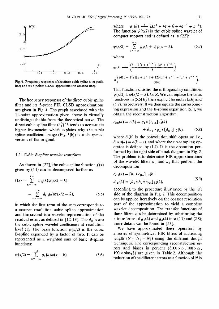
Fig. 4. Frequency responses of the direct cubic spline filter (solid line) and its 5-points CLSD approximation (dashed line).
The frequency responses of the direct cubic spline filter and its 5-point FIR CLSD approximations are given in Fig. 4. The graph associated with the l 1-point approximation given above is virtually undistinguishable from the theoretical curve. The direct cubic spline filter (b3) - 1 tends to accentuate higher frequencies which explains why the cubic spline coefficient image (Fig. 3(b)) is a sharpened version of the original.
5.2. Cubic B-spline wavelet transform
As shown in [22], the cubic spline function f ( x ) given by (5.1) can be decomposed further as
+oo
f ( x ) = ~ c(1) (k)q~(x /2-k) k = - ~
+oo
+ ~ d t ~ ) ( k ) ~ ( x / 2 - k ) , (5.5) k= - o o
in which the first term of the sum corresponds to a coarser resolution cubic spline approximation and the second is a wavelet representation of the residual error, as defined in [12, 13]. The d(~)'s are the cubic spline wavelet coefficients at resolution level (1). The basis function tp(x/2) is the cubic B-spline expanded by a factor of two. It can be represented as a weighted sum of basic B-spline functions:
~o(x/2)= ~ 9 , ( k ) ~ o ( x - k ) , (5.6) k = - o o
where gl(k) ( z ) 81(Z2 ..[_ 4z + 6 + 4z -1 + z - 2 ) .
The function @(x/2) is the cubic spline wavelet of compact support and is defined as in [22]:
+oo
~O(x/2) = ~" g2(k + 1)q~(x - k), (5.7) k = - o o
where
92(k) ' Z ' ( 6 - 4 [ z + z-l] + [z2 +
x C 4 1 6 - l l 9 t [ z + z - a ] + 120[z 2 + z - 2 ] - [ z 3+z-3]) . 5040
This function satisfies the orthogonality condition: if(x/2) i q,(x/2 - k), k e Z. We can replace the basis functions in (5.5) by their explicit formulas (5.6) and (5.7), respectively. If we then equate the correspond- ing expression and the B-spline expansion (5.1), we obtain the reconstruction algorithm:
qo)(k):= c(k) = #1 * [c(1)]T2(k)
+ 6 - 1 * g z * [ d ( l ) ] T 2 ( k ) , (5.8)
where 6g(k) is the convolution shift operator, i.e., 6i * a(k ) = a(k - i), and where the up-sampling op- erator is defined by (1.4). It is the operation per- formed by the right side of block diagram in Fig. 2. The problem is to determine FIR approximations of the wavelet filters hx and h 2 that perform the decomposition
c(1)(k) = [hi * c(0)] ~ 2(k),
d(x)(k) = [61 * hE * C(o)] +2(k), (5.9)
according to the procedure illustrated by the left side of the diagram in Fig. 2. This decomposition can be applied iteratively on the coarser resolution part of the approximation to yield a complete wavelet decomposition. The transfer functions of these filters can be determined by substituting the z-transforms of gl(k) and 92(k) into (2.7) and (2.8); more details can be found in [23].
We have approximated these operators by a series of symmetrical FIR filters of increasing length (N = N~ = N2) using the different design techniques. The corresponding reconstruction er- rors and biases in percent ({100xel, 100xe2, 100 x biasl}) are given in Table 2. Although the reduction of the different errors as a function of N is

172 M. Unser, M. Eden / Signal Processing 36 (1994) 163-174
Table 2 Performance comparison (distortion, aliasing error, and bias in percent) of different design techniques for the FIR approximations of the analysis filters for the cubic B-spline wavelet as a function of N
Truncated impulse Least squares Constrained least N response (TIRD) (LSD) squares (CLSD)
3 {65.14, 31.97, 69.45} {45.03, 10.54, 34.10} {47.87, 10.42,0.0} 7 {33.01, 15.29, 33.57} {22.85, 10.06, 16.78} {23.51, 10.18,0.0}
11 {17.58,8.16, 1 7 . 5 3 } {11.88,6.56,8.82} {12.11,6.63,0.0} 15 {9.4,4.39,9.32} {6.28,3.77,4.71} {6.36,3.81,0.0} 19 {5.02,2.4,4.96} {3.34,2.07,2.52} {3.38,2.09,0.0} 23 {2.66, 1.38,2.62} {1.79, 1.12, 1.35} {1.80, 1.113,0.0} 27 {1.39,0.93, 1 . 3 3 } {0.95,0.60,0.72} {0.96,0.60,0.0} 31 {0.69,0.87,0.58} {0.51,0.32,0.39} {0.51,0.32,0.0}
Table 3 FIR filter coefficients for the cubic B-spline wavelet transform (the kernels 91 and 92 are exact and hi and h2 were obtained via CLSD with N = 27)
k h I h2 gl g2
0 +0.892995 + 1.47401 -- 1,1 + 0.400474 -- 0.468232 - - 2 , 2 - 0.282547 --0.740512 - -3 ,3 - 0.233318 + 0.345154 - - 4,4 + 0.128883 + 0.387516 - - 5 , 5 +0.12641 -0.195611 - - 6 , 6 - 0.0666382 --0.204225 - -7 , 7 -0.0683554 + 0.104778 - 8,8 + 0.0346756 + 0.105509 - 9 , 9 +0.0360809 --0.0541513 - 10, 10 --0.0181137 --0.050628 - 11, 11 --0.0189224 + 0.0258674 -- 12, 12 +0.0072949 + 0.0185111 -- 13,13 + 0.00757909 --0.0094291
+ 0.75 + 0.601786 + 0.5 -- 0.458383 + 0.125 + 0.196032
- 0.0415923 + 0.0030754 - - 0.000024802
not as rapid as in the previous example, the same qualitative observations can be made. The perfor- mance of CLSD is only very slightly suboptimal. Since it has no bias, this approach should definitely be recommended for image processing applica- tions. The detailed results of this constrained op- timization for N = 27 are given in Table 3.
The corresponding symmetrical FIR convolu- tion operators permit the implementation of a cu- bic wavelet transform with a reconstruction error that is of the order of 1%, a level of precision that should be sufficient for most applications. In two dimensions, these operators should be applied
successively along the rows and columns of the data. In this case, there are four types of basis functions corresponding to the different cross- products between the scaling function ~o and the wavelet ff in the spatial variables x and y. This decomposition procedure is illustrated in Fig. 3(c), which was obtained from Fig. 3(b) by filtering and decimation using the FIR kernels in Table 3. The corresponding CPU time was of the order of 13 s. The upper left quadrant in Fig. 3(c) represents the cubic B-spline coefficients at the coarser resolution level, while the three other quadrants contain the three different types of wavelet coefficients (vertical,

M. Unser, M. Eden / Signal Processing 36 (1994) 163-174 173
horizontal, and diagonal). This procedure can be re-applied iteratively on the lowpass component of the image (upper left corner). The B-spline coeffi- cients at the finer resolution level were then recovered by indirect transformation using the op- erators #1 and g2. The initial image was finally reconstructed by indirect B-spline transform (con- volution with b3); it is displayed in Fig. 3(d). The final reconstruction error in this example was less than 0.3% (SNR = 45.43 dB), which was not an- ticipated given the fact that FIR approximations have been used for both the direct cubic spline and B-spline wavelet transforms and that all intermedi- ate filtering results were truncated and stored in small integer format. The fact that this experi- mental error is much smaller than the error speci- fications (~1 and e2) in Table 2 can be explained by the fact that the filter design is based on a worst- case scenario in which the input of the system is an impulse; this latter situation is also equivalent to a white-noise excitation.
The main feature of the example considered im- mediately above is that the underlying scaling func- tions and wavelets are very well localized in time and frequency 1-22]. These properties together with the fast algorithm also described above should make this decomposition a useful tool for the ana- lysis of a variety of non-stationary signals.
5.3. Design of modulated filter banks
In the context of subband coding, the bandpass characteristics of the filter bank is one of the most determinant factors [11, 28]. For this reason, we do not recommend the use of the previous decomposi- tion in such applications. Rather, we would like to have a system that performs a near perfect subband decomposition. One approach to obtaining such a filter bank is to start by designing a good half- band FIR filter gl (k) using any standard procedure [17]. The corresponding highpass filter is then ob- tained by simple modulation
g2(k) = ( - 1)kal(k). (5.10)
We can then use our least-squares design procedure to determine the corresponding analysis (or syn- thesis) filters hi (k) and h2(k). In this case, it would
be judicious to use a slightly modified constraint:
l 'h l + l'h2 = ct, (5.11)
where ~ is chosen in order to guarantee perfect reconstruction of the DC component. This simple modification of the algorithm ensures that the least-squares filters hi(k) and h2(k) are also modulated versions of each other. Moreover, by using the fact that G2 = t~l, we can make use of symmetries and reduce the total complexity of the procedure by a factor of two.
6. Conclusion
In this paper, we have studied a class of FIR approximation techniques for the inversion of FIR convolution operators. The search for an exact solution would require the implementation of infi- nite impulse response operators. Although recur- sive algorithms have been developed for this pur- pose (see, for example, [21]), the IIR approach may not always be practical. The main advantage of FIR filters is their simplicity and the fact that they do not require floating point storage; they are also immune to the propagation of roundoff errors. In addition, FIR algorithms are better suited for par- allel processing.Their principal disadvantage is that they give rise to truncation errors. However, an error of the order of 1% is usually acceptable for most images.
Our design technique is based on the constrained minimization of the inversion (or reconstruction) error associated with an impulse sequence. The corresponding algorithms involve standard matrix algebra and are simple to implement. An important built-in feature is the precise recovery of the DC signal component (zero-bias constraint). This last property may result in a substantial performance improvement, especially when the DC component accounts for a large proportion of the total signal energy, as is typically the case for digital images.
The main use of the one-channel algorithm is for the design of FIR inverse (or deconvolution) filters suitable for signal restoration. The two-channel algorithm is in fact an algebraic least-squares for- mulation of the perfect reconstruction filter bank problem. These procedures are also directly
174 M. Unser, M. Eden / Signal Processing 36 (1994) 163-174
applicable to the design of fast algorithms for con- tinuous signal transforms using shifted basis func- tions of compact support (e.g. B-spline transform and wavelet transform), as illustrated by our exam- ples. Finally, we note that the present computa- tional techniques can be extended for the design of multirate filter banks with more than two channels. In fact, it should be possible to derive a direct algebraic solution for the general N channel case considered in 1-15].
7. References
[1] E.H. Adelson, E. Simoncelli and R. Hingorani, "Ortho- gonal pyramid transforms for image coding", Proc. SPIE Conf. Visual Communication and Image Processing, Cam- bridge, MA, October 1987, pp. 50-58.
[2] C.K. Chui and J.Z. Wang, "On compactly supported spline wavelets and a duality principle", Trans. Amer. Math. Soc., Vol. 330, No. 2, 1992, pp. 903-915.
[3] A. Croisier, D. Esteban and C. Galand, "Perfect channel splitting by use of interpolation, decimation, tree de- composition techniques", Proc. Internat. Conf. on Informa- tion Sciences~Systems, Patras, August 1976, pp. 443-446.
[4] I. Daubechies, "Orthogonal bases of compactly supported wavelets", Comm. Pure Appl. Math., Vol. 41, 1988, pp. 909-996.
[5] J.G. Daugman, "Complete discrete 2-D Gabor transforms by neural networks for image analysis and compression", IEEE Trans. Acoust. Speech Signal Process., Vol. ASSP-36, No. 7, July 1988, pp. 1169-1179.
[6] T. Ebrahimi, T.R. Reed and M. Kunt, "Video coding using a pyramidal Gabor expansion", Proc. Visual Communica- tions and Image Processing '90, Lausanne, Switzerland, 1990, pp. 489-502.
[7] D. Gabor, "Theory of communication", J. Inst. Elec. Eng., Vol. 93, No. III, 1946, pp. 429-457.
[8] F.A. Graybill, Matrices with Application in Statistics, Wad- sworth, Belmont, CA, 1983.
[9] Z. Giilboy and N.C. Geqkinli, "On FIR filters having approximate FIR inverses with a specified LMS error", Signal Processing, Vol. 19, No. 1, January 1990, pp. 9-15.
[10] H.S. Hou and H.C. Andrews, "Cubic splines for image interpolation and digital filtering", IEEE Trans. Acoust. Speech Signal Process., Vol. ASSP-26, No. 6, 1978, pp. 508-517.
[11] V.K. Jain and R.E. Crochiere, "Quadrature mirror filter design in the time domain", IEEE Trans. Acoust. Speech Signal Process., Vol. ASSP-32, No. 2, April 1984, pp. 353-361.
[12] S.G. Mallat, "Multiresolution approximations and wavelet
orthogonal bases of L2(R) '', Trans. Amer. Math. Soc., Vol. 315, No. 1, 1989, pp. 69-87.
[13] S.G. Mallat, "A theory of multiresolution signal decompo- sition: The wavelet representation", IEEE Trans. Pattern Anal. Machine Intell., Vol. PAMI-11, No. 7, 1989, pp. 674-693.
[14] Y. Meyer, Ondelettes et Opbrateurs I: Ondelettes, Her- mann, Paris, 1990.
[15] B. Paillard, J. Soumagne, P. Mabilleau and S. Morisette, "Subband decomposition: An LMS-based algorithm to approximate the perfect reconstruction bank in the general case", IEEE Trans. Signal Process., Vol. 39, No. l, January 1991, pp. 233-238.
[16] J.A. Parker, R.V. Kenyon and D.E. Troxel, "Comparison of interpolating methods for image resampling", IEEE Trans. Med. Imaging, Vol. MI-2, No. 1, 1983, pp. 31-39.
[17] J.G. Proakis and D.G. Manolakis, Introduction to Digital Signal Processing, Macmillan, New York, 1990.
[18] I.J. Schoenberg, Cardinal Spline Interpolation, SIAM, Philadelphia, PA, 1973.
[19] E.P. Simoncelli and E.H. Adelson, "Non-separable exten- sions of quadrature mirror filters to multiple dimensions", Proc. IEEE, Vol. 78, No. 4, 1990, pp. 652-664.
[20] M. Unser and A. AIdroubi, "Polynomial splines and wavelets - A signal processing perspective", in: C.K. Chui, ed., Wavelets - A Tutorial in Theory and Applications, Academic Press, San Diego, 1992, pp. 91-122.
[21] M. Unser, A. Aldroubi and M. Eden, "Fast B-spline trans- forms for continuous image representation and interpola- tion", IEEE Trans. Pattern Anal. Machine lntell., Vol. 13, No. 3, March 1991, pp. 277-285.
[22] M. Unser, A. Aldroubi and M. Eden, "On the asymptotic convergence of B-spline wavelets to Gabor functions", IEEE Trans. Inform. Theory, Vol. 38, No. 2, 1992, pp. 864-872.
[23] M. Unser, A. Aldroubi and M. Eden, "A family of poly- nomial spline wavelet transforms", Signal Processing, Vol. 30, No. 2, January 1993, pp. 141-162.
[24] P.P. Vaidyanathan, "Quadrature mirror filter banks, M- band extensions and perfect-reconstruction technique", IEEE ASSP Mag., Vol. 4, July 1987, pp. 4-20.
[25] M. Vetterli, "Multi-dimensional sub-band coding: some theory and algorithms", Signal Processing, Vol.6, No. 2, April 1984, pp. 97-112.
[26] M. Vetterli, "A theory of multirate filter banks", IEEE Trans. Acoust. Speech Signal Process., Vol. ASSP-35, No. 3, March 1987, pp. 356-372.
[27] M. Vetterli and C. Herley, "Wavelets and Filter Banks: Theory and Design", IEEE Trans. Signal Process., Vol. SP-40, No. 9, September 1992, pp. 2207-2232.
[28] J.W. Woods and S.D. O'Neil, "Sub-band coding of im- ages", IEEE Trans. Acoust. Speech Signal Process., Vol. ASSP-34, October 1986, pp. 1278-1288.