Embed Size (px)
Citation preview

Process switches and relay circuits
This worksheet and all related files are licensed under the Creative Commons Attribution License,version 1.0. To view a copy of this license, visit http://creativecommons.org/licenses/by/1.0/, or send aletter to Creative Commons, 559 Nathan Abbott Way, Stanford, California 94305, USA. The terms andconditions of this license allow for free copying, distribution, and/or modification of all licensed works bythe general public.
1

Questions
Question 1
Switches, whether they be hand-actuated or actuated by a physical process, come in two varieties:normally-open (NO) and normally-closed (NC). You are probably accustomed to seeing both types of switchrepresented in pushbutton form on schematic diagrams:
Normally-openpushbutton switch pushbutton switch
Normally-closed
Normally-open pushbutton switches close (pass current) when actuated (pressed). When un-actuated,they return to their “normal” (open) state.
Normally-closed pushbutton switches are just the opposite: they open (stop current) when actuated(pressed) and return to their “normal” (closed, passing current) state when un-actuated.
This is simple enough to comprehend: the “normal” status of a momentary-contact pushbutton switchis the state it is in when no one is touching it. When pressed, the pushbutton switch goes to the other(opposite) state.
Things get more confusing, though, when we examine process switches, such as pressure switches, levelswitches, temperature switches, and flow switches:
Normally-open Normally-closedpressure switch pressure switch
Normally-open Normally-closedlevel switch level switch
Normally-open Normally-closed
Normally-open Normally-closed
temperature switch temperature switch
flow switch flow switch
Define “normal” for each of these process switches. In other words, explain what condition(s) eachprocess switch must be in to ensure it is in the “normal” state; and conversely, what condition(s) need to beapplied to each switch to force it into its other state.
file i02966
2

Question 2
Limit switches are electrical switches designed to actuate based on the motion or position of an object,rather than the touch of a human operator. Simple limit switches rely on direct, physical contact, using alever, sometimes tipped with a roller for low friction:
Com NC NO
Direct-contact limit switch
Battery Light bulb
Show how you would connect the limit switch in the above illustration so that it makes the light turnoff when actuated (i.e. the light will be on when no one touches the switch lever).
file i02242
3

Question 3
An improvement over direct-contact limit switches for many applications is the inductive proximity
switch. This type of switch actuates simply when an object gets near it – no direct physical contact necessary!Explain how these devices work, and what kinds of material they are able to detect.
Inductive proximity switches are powered devices by necessity. They usually require a DC voltage forpower, and their output is usually not a dry switch contact. Instead, it is usually a transistor, with theoutput signal being standard TTL logic (0 to 5 volts). Inductive proximity switches are often manufacturedas three-wire devices:
(+)
Output
Switch actuateswhen object
approaches thisend!
Gnd
Show how you would connect the limit switch in the above illustration so that it makes the LED turn on
when actuated, assuming the switch’s internal transistor is configured to source current through the outputlead.
Suggestions for Socratic discussion
• Identify an object a capacitive proximity switch would be able to detect.• Identify an object an ultrasonic proximity switch would be able to detect.• Identify an object an inductive proximity switch would not be able to detect.• Identify an object an optical proximity switch would not be able to detect.
file i02243
4

Question 4
An improvement over direct-contact limit switches for many applications is the inductive proximity
switch. This type of switch actuates simply when an object gets near it – no direct physical contact necessary!Explain how these devices work, and what kinds of material they are able to detect.
Inductive proximity switches are powered devices by necessity. They usually require a DC voltage forpower, and their output is usually not a dry switch contact. Instead, it is usually a transistor, with theoutput signal being standard TTL logic (0 to 5 volts). Inductive proximity switches are often manufacturedas three-wire devices:
(+)
Output
Switch actuateswhen object
approaches thisend!
Gnd
Show how you would connect the limit switch in the above illustration so that it makes the LED turnon when actuated, assuming the switch’s internal transistor is configured to sink current through the outputlead.
Suggestions for Socratic discussion
• Identify an object an inductive proximity switch would be able to detect.• Identify an object an optical proximity switch would be able to detect.• Identify an object a capacitive proximity switch would not be able to detect.• Identify an object an ultrasonic proximity switch would not be able to detect.
file i02244
5

Question 5
An alternative to the conventional schematic diagram in AC power control systems is the ladder diagram.In this convention, the “hot” and “neutral” power conductors are drawn as vertical lines near the edges ofthe page, with all loads and switch contacts drawn between those lines like rungs on a ladder:
"Hot"
To 480VAC
120 VAC
"Neutral"
Toggle switch Indicator light
Limit switch Solenoid coil
Temperature switch
Fuse
Fuse Fuse
As you can see, the symbolism in ladder diagrams is not always the same as in electrical schematicdiagrams. While some symbols are identical (the toggle switch, for instance), other symbols are not (thesolenoid coil, for instance).
Re-draw this ladder diagram as a schematic diagram, translating all the symbols into those correct forschematic diagrams.
file i02302
6

Question 6
Explain what the following “ladder-logic” circuit does, and identify the meaning of each symbol in thediagram:
L1 L2
TSH
TSL
Temp. high
Temp. low
TSHH
Cooling watersolenoid
Suggestions for Socratic discussion
• Explain why the TSH uses a normally-open contact instead of a normally-closed contact.• Explain why the TSL uses a normally-closed contact instead of a normally-open contact.• Based on what we see in this diagram, determine whether the electric solenoid valve allows cooling water
to flow when energized, or when de-energized.• What do the designations “L1” and “L2” refer to in ladder-logic electrical diagrams?• Suppose switch TSL has a trip setting of 105 oF (falling) and a deadband value of 2 oF. Explain how
this switch will respond to a rising and falling temperature.• Suppose we wished to have switch TSHH activate two different alarm lights instead of just one. Modify
the circuit diagram accordingly.
file i00364
Question 7
Identify which lamp in the following ladder-logic diagram is the high-flow alarm and which is the low-flow
alarm, given the flow switch symbols shown:
L1 L2
file i00548
7

Question 8
Limit switches are often used on the doors of electrical enclosures and cabinets to automatically shutoff power or shut down a machine’s function if anyone opens the door for maintenance purposes. The limitswitch is typically mounted in such a way that a shut door holds the switch lever in the “actuated” position.When the door opens wide, the limit switch lever is released and the switch returns to its “normal” status.
Draw the appropriate limit switch symbol in this ladder logic diagram so that the control circuit (shownas a rectangular box) gets shut down if ever someone opens the cabinet door:
L1 L2
Control circuit
???
Be sure to denote whether this limit switch needs to be normally-open (N.O.) or normally-closed (N.C.).file i02967
8

Question 9
Determine the functions of all pressure switches and relays in this steam boiler monitoring circuit, andwhat each of their designations mean:
L1 L2
PSH-1
PSHH-2
solenoid
PSL-1
Boiler shutdown
Low steamwarning lamp
warning lampHigh steam
200 PSI
80 PSI
220 PSI
TD1
TD1
10 sec
Also, explain the significance of the switch symbols: normally open versus normally closed. The time-delay relay (TD1) is especially important here!
Finally, add a “Lamp Test” pushbutton switch to this circuit which will force all lamps to energizewhen pressed, in order to test the proper operation of the lamps without waiting for an abnormal processcondition to occur.
Suggestions for Socratic discussion
• Why do you suppose a time-delay relay is used in this particular control application?• Is the boiler shutdown solenoid energize-to-trip or de-energize-to-trip? Explain how we can tell from an
examination of the schematic.• Identify where in this circuit you could install a PSHHH (pressure switch high-high-high) that would
trip the boiler immediately.• Identify a circuit fault that would cause the boiler to needlessly shut down (a “safe” fault).• Identify a circuit fault that would cause the boiler to not be able to shut down when it needs to (a
“dangerous” fault).
file i00221
9
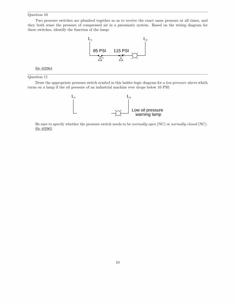
Question 10
Two pressure switches are plumbed together so as to receive the exact same pressure at all times, andthey both sense the pressure of compressed air in a pneumatic system. Based on the wiring diagram forthese switches, identify the function of the lamp:
L1 L2
85 PSI 115 PSI
file i02964
Question 11
Draw the appropriate pressure switch symbol in this ladder-logic diagram for a low-pressure alarm whichturns on a lamp if the oil pressure of an industrial machine ever drops below 10 PSI:
L1 L2
Low oil pressurewarning lamp
Be sure to specify whether the pressure switch needs to be normally-open (NC) or normally-closed (NC).file i02965
10

Question 12
Determine the statuses of all lamps and relay coils in this circuit, given the following process conditions:
L1 L2
Trip = 4 ftPushbutton A CR1
CR1 Pushbutton B BlueTrip = 30 PSI
Trip = 178 oF CR1 RedTrip = 5 GPM
Amber
• Flow = 3.5 GPM• Pressure = 41 PSI• Temperature = 155 oF• Level = 1.3 ft• Pushbutton A = unpressed
• Pushbutton B = unpressed
file i01087
11

Question 13
Determine the statuses of all lamps and relay coils in this circuit, given the following process conditions:
L1 L2
Trip = 4 ft
Pushbutton A CR1
CR1
Pushbutton B
Trip = 30 PSI
Trip = 178 oF
RedTrip = 5 GPM
Amber
CR2
CR2
• Flow = 4 GPM• Pressure = 24 PSI• Temperature = 190 oF• Level = 2.5 ft• Pushbutton A = pressed
• Pushbutton B = pressed
file i01088
12

Question 14
Determine the statuses of all lamps and relay coils in this circuit, given the following process conditions:
L1 L2
Trip = 4 ftPushbutton A CR1
CR1Pushbutton B Blue
Trip = 30 PSITrip = 178 oF CR1 Red
Trip = 5 GPM
Amber
• Flow = 7.9 GPM• Pressure = 36 PSI• Temperature = 210 oF• Level = 7.1 ft• Pushbutton A = pressed
• Pushbutton B = unpressed
file i01089
13
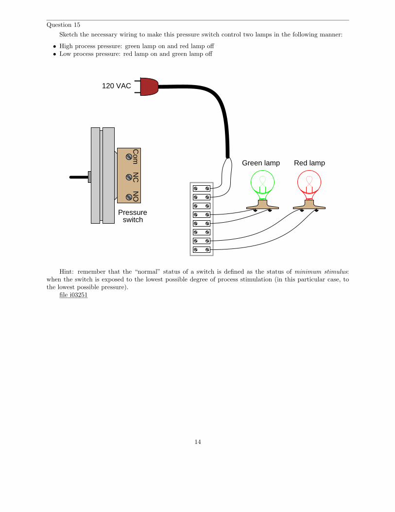
Question 15
Sketch the necessary wiring to make this pressure switch control two lamps in the following manner:
• High process pressure: green lamp on and red lamp off• Low process pressure: red lamp on and green lamp off
Com
NC
NO
Red lampGreen lamp
120 VAC
Pressureswitch
Hint: remember that the “normal” status of a switch is defined as the status of minimum stimulus:when the switch is exposed to the lowest possible degree of process stimulation (in this particular case, tothe lowest possible pressure).
file i03251
14

Question 16
Examine the following electronic level switch circuit:
Liquid
Relay
R1Q1
Probe
Grounded metal vessel
+15 V
Identify what kinds of process liquids this level switch would be applicable to, and why. Also, identifywhich ladder-logic switch symbol would be appropriate for this particular level switch:
Normally-open
(N.O.)
Normally-closed
(N.C.)
Qualitatively determine the following component voltage drops in the circuit with low level and withhigh level (i.e. write “low” or “high” voltage rather than try to calculate actual values):
Component Low-level condition High-level condition
R1Q1 (between drain and source)
Relay coil
file i00513
15
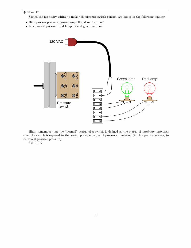
Question 17
Sketch the necessary wiring to make this pressure switch control two lamps in the following manner:
• High process pressure: green lamp off and red lamp off• Low process pressure: red lamp on and green lamp on
Com
NC
NO
Red lampGreen lamp
120 VAC
Pressureswitch
Com
NO
NC
Hint: remember that the “normal” status of a switch is defined as the status of minimum stimulus:when the switch is exposed to the lowest possible degree of process stimulation (in this particular case, tothe lowest possible pressure).
file i01972
16
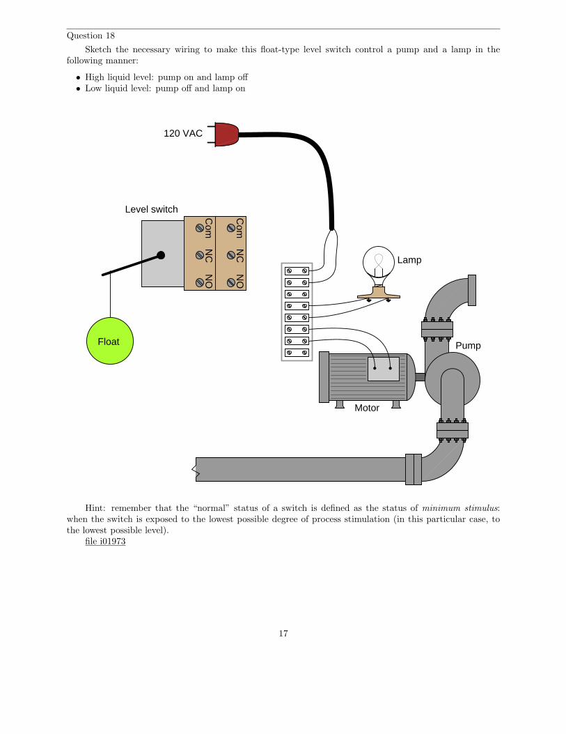
Question 18
Sketch the necessary wiring to make this float-type level switch control a pump and a lamp in thefollowing manner:
• High liquid level: pump on and lamp off• Low liquid level: pump off and lamp on
120 VAC
Com
NO
NC
Com
NO
NC
Lamp
Motor
PumpFloat
Level switch
Hint: remember that the “normal” status of a switch is defined as the status of minimum stimulus:when the switch is exposed to the lowest possible degree of process stimulation (in this particular case, tothe lowest possible level).
file i01973
17

Question 19
Explain the operation of this circuit:
Relay
Trip = 45 PSI
Blu
Grn
Red
+ −
24 VDC1 amp
Trip = 1 foot 3 inches
file i02304
18
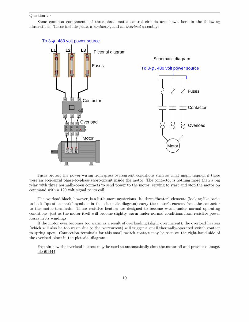
Question 20
Some common components of three-phase motor control circuits are shown here in the followingillustrations. These include fuses, a contactor, and an overload assembly:
Motor
T1
To 3-φ , 480 volt power source
L1 L2 L3
Contactor
T2 T3
Reset
Overload
Schematic diagram
Motor
Overload
Contactor
Fuses
Fuses
To 3-φ , 480 volt power source
Pictorial diagram
Fuses protect the power wiring from gross overcurrent conditions such as what might happen if therewere an accidental phase-to-phase short-circuit inside the motor. The contactor is nothing more than a bigrelay with three normally-open contacts to send power to the motor, serving to start and stop the motor oncommand with a 120 volt signal to its coil.
The overload block, however, is a little more mysterious. Its three “heater” elements (looking like back-to-back “question mark” symbols in the schematic diagram) carry the motor’s current from the contactorto the motor terminals. These resistive heaters are designed to become warm under normal operatingconditions, just as the motor itself will become slightly warm under normal conditions from resistive powerlosses in its windings.
If the motor ever becomes too warm as a result of overloading (slight overcurrent), the overload heaters(which will also be too warm due to the overcurrent) will trigger a small thermally-operated switch contactto spring open. Connection terminals for this small switch contact may be seen on the right-hand side ofthe overload block in the pictorial diagram.
Explain how the overload heaters may be used to automatically shut the motor off and prevent damage.file i01444
19

Question 21
Draw a ladder logic control circuit for the electric motor of an air compressor, controlled by two pressureswitches: one switch turns the motor on when the pressure falls to 80 PSI, while the other switch turns themotor off when the pressure rises to 105 PSI:
L1 L2
motor480 VAC
3 θ
MOL
Be sure to include the overload (OL) contact in the 120 volt control circuit (L1 & L2), and include amanual on/off switch as well.
file i00799
20

Question 22
A form of liquid level switch called a tilt switch is often used for detecting sewage level in “lift stations”where sewage collected from homes via gravity is pumped out of the collection sump to the wastewatertreatment plant (usually located miles away):
Empty
Pump Pump
LSL
LSH LSH
LSL
To WWTP To WWTP
From homes From homes
Pump
To WWTP
From homes
LSH
LSL
Full
Tilt switches often use a small glass vial containing liquid mercury as the tilt sensor. Explain howa glass tube partially filled with mercury works as an electrical tilt switch, and also perform a “thoughtexperiment” where you describe this system’s function from start to finish through a complete start-stopcycle of the pump motor:
L1 L2
LSHLSL
M1
M1 OL
motor
OL
To 3-phaseAC power
M1
Suggestions for Socratic discussion
• What would happen if the OL switch failed open in this system?• What would happen if the LSL switch failed open in this system?• What would happen if the LSH switch failed open in this system?• What would happen if the LSL switch failed shorted in this system?• What would happen if the LSH switch failed shorted in this system?• What would happen if the LSH switch failed shorted in this system?
21

• What would happen if the M1 seal-in contact failed open in this system?• What would happen if the M1 seal-in contact failed shorted in this system?
file i00303
22

Answers
Answer 1
The “normal” condition for a process switch is the condition of least stimulus. For example:
• A pressure switch will be in its “normal” state when there is minimum pressure applied
• A level switch will be in its “normal” state when there is no level detected by the switch
• A temperature switch will be in its “normal” state when it is cold
• A flow switch will be in its “normal” state when there is no flow detected by the switch
Answer 2
Com NC NOBattery Light bulb
Light bulb turns off when limit switch actuates
Answer 3
(+)
Output
Switch actuateswhen object
approaches thisend!
Gnd
Answer 4
23

Answer 5
To 480VAC
"Hot"
"Neutral"
Light Solenoid Heater
Answer 6
This is an automatic cooling system with high and low temperature alarms.
Answer 7
L1 L2
High flow alarm
Low flow alarm
Answer 8
L1 L2
Control circuit
Limit switch
(N.O.)
24

Answer 9
• PSL = Pressure Switch, Low• PSH = Pressure Switch, High• PSHH = Pressure Switch, High-High
Both warning lamps should be off when the steam pressure is between 80 and 200 PSI. The boiler willautomatically shut down when the shutdown solenoid de-energizes, and this will happen if the steam pressureexceeds 220 PSI for at least 10 seconds.
The difference between a “normally open” process switch and a “normally closed” process switch isvitally important for technicians to understand. The “normal” condition referred to in each label does not
mean the condition that is typical for the process. Rather, it refers to a condition where the switch issubjected to minimum stimulus. In other words, the “normal” condition for each switch is:
• Temperature switch = cold• Pressure switch = low or no pressure• Level switch = empty vessel• Flow switch = low or no flow
Answer 10
The lamp’s illumination signifies a condition where the compressed air pressure is somewhere between85 and 115 PSI. The lamp will turn off if the pressure drops below 85 PSI or if the pressure rises above 115PSI.
Answer 11
L1 L2
Low oil pressurewarning lamp
10 PSI
As the diagram shows, this needs to be a normally-closed switch.
25

Answer 12
Fully annotated circuit schematic: “X” representing an open contact or de-energized load, and “→”
representing a closed contact or energized load
L1 L2
Trip = 4 ftPushbutton A CR1
CR1 Pushbutton B BlueTrip = 30 PSI
Trip = 178 oF CR1 RedTrip = 5 GPM
Amber
Recall that a process switch will be in its resting (“normal”) condition when the stimulus value is lessthan the trip threshold, and will be in its actuated condition when the stimulus exceeds the threshold.
Therefore,
• CR1 coil = de-energized
• Blue lamp = energized
• Red lamp = de-energized
• Amber lamp = energized
26
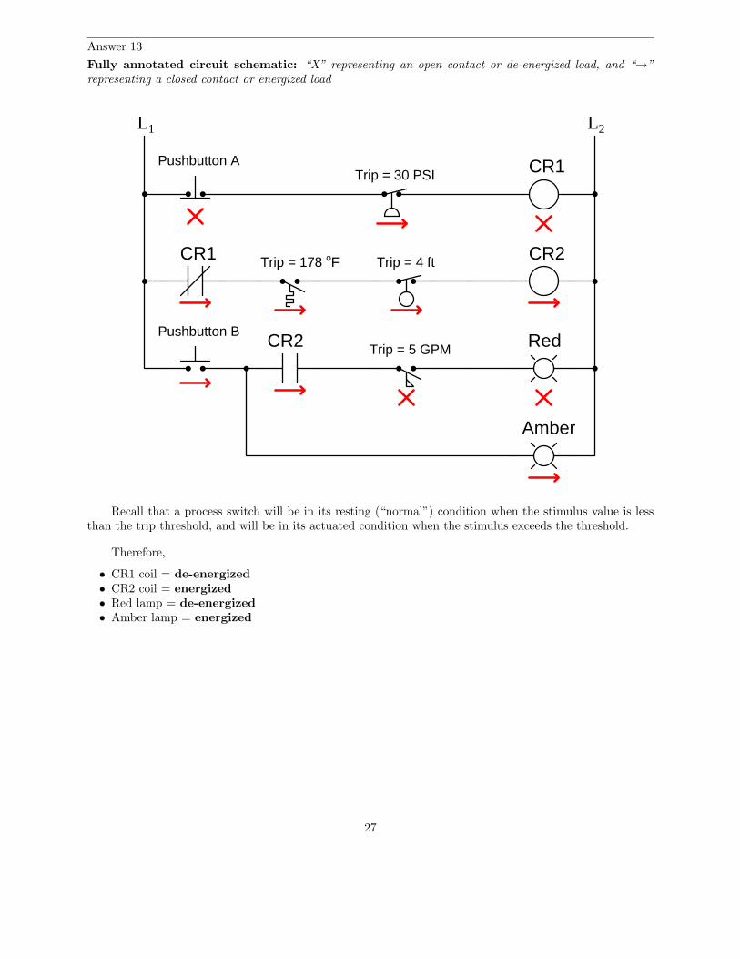
Answer 13
Fully annotated circuit schematic: “X” representing an open contact or de-energized load, and “→”
representing a closed contact or energized load
L1 L2
Trip = 4 ft
Pushbutton A CR1
CR1
Pushbutton B
Trip = 30 PSI
Trip = 178 oF
RedTrip = 5 GPM
Amber
CR2
CR2
Recall that a process switch will be in its resting (“normal”) condition when the stimulus value is lessthan the trip threshold, and will be in its actuated condition when the stimulus exceeds the threshold.
Therefore,
• CR1 coil = de-energized
• CR2 coil = energized
• Red lamp = de-energized
• Amber lamp = energized
27
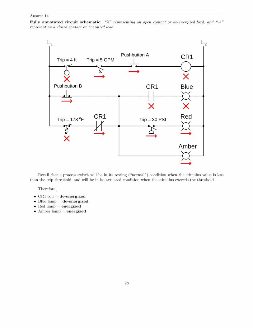
Answer 14
Fully annotated circuit schematic: “X” representing an open contact or de-energized load, and “→”
representing a closed contact or energized load
L1 L2
Trip = 4 ftPushbutton A CR1
CR1
Pushbutton B Blue
Trip = 30 PSITrip = 178 oF
CR1
Red
Trip = 5 GPM
Amber
Recall that a process switch will be in its resting (“normal”) condition when the stimulus value is lessthan the trip threshold, and will be in its actuated condition when the stimulus exceeds the threshold.
Therefore,
• CR1 coil = de-energized
• Blue lamp = de-energized
• Red lamp = energized
• Amber lamp = energized
28

Answer 15
This is just one possible solution:
Com
NC
NO
Red lampGreen lamp
120 VAC
Pressureswitch
Answer 16
This is a graded question – no answers or hints given!
29

Answer 17
This is just one possible solution:
Com
NC
NO
Red lampGreen lamp
120 VAC
Pressureswitch
Com
NO
NC
30

Answer 18
This is just one possible solution:
120 VAC
Com
NO
NC
Com
NO
NC
Lamp
Motor
PumpFloat
Level switch
Answer 19
The blue lamp will be energized whenever the pressure switch senses a pressure that is less than 45 PSI.
The red and green lamps will both be de-energized whenever the level senses a level less than 1 foot3 inches. If that switch senses a level greater than 1 foot 3 inches, either the red lamp or the green lampwill energize (not both simultaneously!) based on the pressure switch’s state: a pressure less than 45 PSIenergizes the relay coil and energizes the green lamp, while a pressure greater than 45 PSI de-energizes therelay coil and energizes the red lamp.
31

Answer 20
If you thought the overload heaters would open up like fuses in the event of an overload condition(becoming too warm) to directly interrupt motor current, you have made a very common error! Don’t feelbad, though – I won’t tell anyone.
In order for the overload assembly to automatically shut down the motor, its small switch must beconnected to something. I’ll let you figure out what that something is!
Answer 21
L1 L2
motor480 VAC
3 θ
MOL
OLM105 PSI80 PSI
M
On/off
Answer 22
Be sure to review the operation of this simple motor start-stop circuit in your answer!
32