Embed Size (px)
Citation preview

Process planning for the subtractive rapid manufacturing of heterogeneous materials: Applications for automated bone implant manufacturing
by
Shuangyan Lei
A dissertation submitted to the graduate faculty
In partial fulfillment of the requirements for the degree of
DOCTOR OF PHILOSOPHY
Major: Industrial Engineering
Program of Study Committee: Matthew Frank, Major Professor
Frank Peters John Jackman
Iris Rivero Eliot Winer
Iowa State University Ames, Iowa
2014
Copyright © Shuangyan Lei, 2014. All rights reserved

ii
TABLE OF CONTENTS
TABLE OF CONTENTS ................................................................................................... ii
ABSTRACT ..................................................................................................................... iv
CHAPTER 1. INTRODUCTION ....................................................................................... 1
1.1 Background ............................................................................................................ 1
1.2 Motivation ............................................................................................................... 9
1.3 Objective .............................................................................................................. 11
1.4 Reference ............................................................................................................ 12
CHAPTER 2. LITERATURE REVIEW ........................................................................... 16
2.1 Heterogeneous Object Modeling and Manufacturing ........................................... 16
2.2 Process Planning for Rapid Manufacturing .......................................................... 19
2.2.1 Fixture Design................................................................................................ 19
2.2.2 Setup Orientation Determination ................................................................... 22
2.3 Process Planning for Rapid Manufacturing of Heterogeneous Materials ............. 26
2.4 Reference ............................................................................................................ 29
CHAPTER 3. A METHOD TO REPRESENT HETEROGENEOUS MATERIALS FOR RAPID PROTOTYPNG – THE MATRYOSHKA APPROACH ....................................... 38
Abstract ...................................................................................................................... 38
3.1 Background .......................................................................................................... 39
3.2 The Matryoshka Shell Model................................................................................ 46
3.2.1 Using a Matyroshka Model for Bone Implant Harvesting ............................... 52
3.2.2 Creating a Discretized Slice Model ................................................................... 55
3.2.3 Density Score and Similarity Score Calculation ............................................. 57
3.3 Implementation Example ..................................................................................... 60
3.3.1 Matryoska Model Generation and Harvesting Search ................................... 60
3.3.2 Implant Harvesting Using CNC-RP ................................................................ 65
3.4 Conclusion ........................................................................................................... 68
3.5 Reference ............................................................................................................ 69
CHAPTER 4. AUTOMATED FIXTURE DESIGN FOR THE SUBTRACTIVE RAPID MACHINING OF HETEROGENEOUS MATERIALS: APPLICATIONS FOR NATURAL BONE IMPLANT MANUFACTURING ........................................................................... 74
Abstract ...................................................................................................................... 74
4.1 Introduction .......................................................................................................... 75
4.2 Related Work ....................................................................................................... 81
4.3 Overview of Sacrificial Support Generation for a Bone Implant ........................... 83
4.4 Implementation Example ................................................................................... 100
4.5 Conclusion ......................................................................................................... 105
4.6 Reference .......................................................................................................... 106

iii
CHAPTER 5: CONCLUSION AND FUTURE WORK .................................................. 110
5.1 Summary ........................................................................................................... 110
5.2 Future Work ....................................................................................................... 113
5.2.1 Improving the Harvest Search Algorithm ..................................................... 113
5.2.2 Rotation Axis Selection ................................................................................ 114
ACKNOWLEDGEMENTS ........................................................................................... 118

iv
ABSTRACT
This research presents a subtractive rapid manufacturing process for heterogeneous
materials, in particular for custom shaped bone implants. Natural bone implants are
widely used in the treatment of severe fractures or in tumor removal. In order for the
human body to accept the bone implant material and heal properly, it is essential that
the bone implant should be both mechanically and biologically compatible. Currently,
the challenge of having correctly shaped natural bone implants created from an
appropriate material is met through hand-shaping done by a surgeon.
CNC-RP is a rapid machining method and software that can realize a fully automated
Subtractive Rapid Prototyping (RP) process, using a 3-axis milling machine with a 4th
axis indexer for multiple setup orientations. It is capable of creating accurate bone
implants from different clinically relevant material including natural bone. However, there
are major challenges that need to be overcome in order to implement automated shape
machining of natural bones. They are summarized as follows:
(1) Unlike homogeneous source materials for which a part can be machined from any
arbitrary location within the original stock, for the case of donor bones, the site and
orientation of implant harvest need to consider the nature of the heterogeneous internal
bony architecture.
(2) For the engineered materials, the source machining stock is in the convenient form
of geometrically regular shapes such as cylinders or rectangular blocks and the entities
of sacrificial supports can connect the part to the remaining stock material. However,

v
irregularly-shaped bones and the heterogeneity of bone make the design of a fixture
system for machining much more complicated.
In this dissertation, two major areas of research are presented to overcome these
challenges and enable automated process planning for a new rapid manufacturing
technique for natural bone implants.
Firstly, a new method for representing heterogeneous materials using nested STL shells
is proposed. The nested shells model is called the Matryoshka mode, based in
particular on the density distribution of human bone. The Matryoshka model is
generated via an iterative process of thresholding the Hounsfield Unit (HU) data from a
computed tomography (CT) scan, thereby delineating regions of progressively
increasing bone density. Then a harvesting algorithm is developed to determine a
suitable location to generate the bone implant from within the donor bone is presented.
In this harvesting algorithm, a density score and similarity score are calculated to
evaluate the overall effectiveness of that harvest site.
In the second research area, an automated fixturing system is proposed for securing the
bone implant during the machining process. The proposed method uses a variant of
sacrificial supports (stainless surgical screws) to drill into appropriate locations and
orientations through the free-form shaped donor bone, terminating at proper locations
inside the solid part model of the implant. This automated fixturing system has been
applied to machine several bone implants from surrogate bones to 3D printed
Matryoshka models. Finally, the algorithms that are developed for setup planning are

vi
implemented in a CAD/CAM software add-on called “CNC-RPbio”. The results of this
research could lead to a clinically relevant rapid machining process for custom shaped
bone implants, which could create unique implants at the touch of a button. The
implication of such high accuracy implants is that patients could benefit from more
accurate reconstructions of trauma sites, with better fixation stability; leading to
potentially shorter surgeries, less revisions, shorter recovery times and less likelihood of
post-traumatic osteoarthritis, to name a few.

1
CHAPTER 1. INTRODUCTION
With recent advancements in the rapid manufacturing technology, complex parts with
varying material properties can now be created effectively. This research focuses on
developing process planning algorithms for subtractive rapid manufacturing of parts with
heterogeneous materials, in particular, developing rapid manufacturing methods to
create custom bone implants from donated human bones. This chapter presents
challenges in process planning for this system, followed by the motivation and objective
of this research.
1.1 Background
Rapid Prototyping (RP), also known as layer based manufacturing, generally refers to
techniques that can create 3D parts by the process of successively adding 2D layers of
material [1]. The generic idea of “RP” has been more recently garnering the name
“Additive Manufacturing” owing to the method of construction and the increasing
functional use of the components created. This manufacturing approach takes
complicated 3D geometry and slices it into simple 2D entities, which can be easily
created through simpler fabrication processes. Most existing “RP” techniques are
additive in nature, some are hybrid combinations of additive and subtractive methods,
while some are purely subtractive. Commercial additive RP technologies include
methods such as Fused Deposition Modeling (FDM), Stereolithography (SLA), Three
Dimensional Printing (3DP), Laser Engineered Net Shaping (LENS), Selective Laser
Melting (SLM), etc. [2-5]. In particular, the multi-material 3D printing system Connex

2
developed by Object Ltd. has the capability of printing parts made of up to fourteen
different materials in a single print.
However, Additive Manufacturing is limited in the variety of materials available and
geometric accuracy possible. The geometry error is usually caused by the stair-case
effect of adding material layer by layer. Though a wide range of homogeneous and
heterogeneous material mixtures have been employed in additive manufacturing, there
is still a need for developing additional materials [6, 7]. Moreover, many of the materials
which are commonly used in additive RP manufacturing processes cannot be used
directly for fabricating functional models, especially dimensional tolerances or surface
finishes when the part is required to be made from metal [8].
In order to improve the variety of materials available, subtractive rapid manufacturing
has been developed in an effort to produce functional prototypes using appropriate
materials. It can be used to rapidly machine a variety of functional parts with high
accuracy and relatively low cost [9-11]. CNC-RP is a version of subtractive RP that can
create functional 3D parts from a wide variety of materials [12-17]. It provides
completely automated process planning, from initial setup planning through NC code
generation. In this system, the stock material is fixed between two opposing chucks and
is oriented by a rotary device. For each orientation, all visible surfaces of the part are
machined to create part geometry. During the machining process, sacrificial supports
are implemented as small features added to the part model geometry and incrementally
created during the machining process along with other part features. At the end of the
machining process, the supports are left to connect the part and stock material and then

3
the supports are subsequently cut to remove the part. Figure 1 illustrates the process
steps for creating a part in CNC-RP. The cylindrical stock is shown fixed between
opposing chucks in Figure 1(a). Four supports are used as shown in Figure 1(b), and 4
orientations are needed to machine the part and supports as shown in Figure 1(b.1-b.4).
By the end of machining process, only permanent supports are remaining to provide
stiffness to the part (Figure 1(b.5)). Lastly, the part is cut from the stock by sawing the
two remaining supports (Figure 1(b.6)).
(6)(2)
(4)
(3)
(1) (5)
Opposing 3-Jaw chucks
Round
Rotary IndexerEnd Mill
Axis of Rotation
(Side View) (Side View)
Rotate StockRotate StockRotate Stock
Side View
(7) Final Steel Part
(a) (b)
Figure 1. CNC-RP process (a) Rotary fixture setup; (b) Process sequence of steps (b.1
- b.4) to expose component geometry and (b.5 - b.6) to expose sacrificial supports.
In the current CNC-RP process, the source material usually has a regular shape, such
as a cylindrical or rectangular bar and the part can be machined from anywhere
arbitrarily within the original stock. However, challenges exist when manufacturing parts
with multi-material or heterogeneous materials, in particular, since both the part and
stock material could have an arbitrary shape and/or arbitrary heterogeneous material
structure. As opposed to homogenous material from round bar, one would now need to
determine a proper site from within the stock where the part can be feasibly machined.

4
One particularly challenging heterogeneous material is natural bone. Native human
bone’s density distribution from inside to outside spans a significant range. To illustrate,
Figure 2 shows a cross sectional view of a femur bone, showing the spongy, low density
trabecular bone in the middle, versus the high-density cortical bone on the outside.
Bone implants are widely used in the treatment of missing pieces of bone due to trauma
or other cases of bone loss (Figure 3). An estimated 15.3 million fractures occur
annually in the United States, with some requiring significant bone reconstruction,
requiring a burdensome task to perform the implant creation [19]. At the same time, the
aging populations of the world and the increasing incidence of osteoporosis indicate that
the repair of bone defects and fractures will be a major challenge for orthopedic
surgeons [20]. Currently, persons over 65 years account for 12% to 13% of the total
population; by 2030 it is expected this number will increase to 20%, an increase of more
than 50% [19]. These people are at great risk of bone defects caused by osteoporotic
fracture (80% of fractures in women over 60 years old [21]), infections, or cancer
metastases. The treatment of bone defects that cannot self-repair may then become a
Figure 3. Typical bone
implant (pink).
Figure 2. A Cross-sectional
view of a femur bone [18].
Cortical bone
Trabecular
bone
Host bone
Bone implant

5
public health issue, resulting in a significant cost to society. The estimated cost for
treatment of patients with musculoskeletal conditions in the USA already reached $510
billion a decade ago in 2004 [19].
Bone grafting is a surgical procedure that places new bone into spaces between or
around fractured bone to aid in healing. Bone grafting is possible because the bone
possesses the capacity for regeneration as part of the repair process in response to
injury. The application of the bone graft can be traced back to 1821, where the first
clinical autograft was performed in Germany in an attempt to fill an animal skull defect.
In 1879, Sir William Macewen successfully used a bone graft from other patients to
reconstruct a 4 year old boy’s proximal humerus, which is considered to be the first
documented allograft procedure [22, 23].
Autologous bone grafting involves utilizing bone obtained from a healthy area of the
patient’s skeleton itself. It is the gold standard for augmentation of bone healing. It is
known to be completely tissue compatible, and has no risk for disease transmission.
Clinically, autologous bone grafting is commonly used in the treatment of fracture non-
unions [24-27]. When a fracture fails to heal, it can result in non-unions. While non-
unions can occur in any bone, they are most common in the tibia, humers, talus, and
fifth metatarsal bone. However, failure rates have been reported to be as high as 50%,
and this could be caused by different types of harvesting, handling, and/or the
implementation method used and differences between patient conditions [28].
Autologous bone grafting has some significant drawbacks. Firstly, an additional surgical
site is required, resulting in adding another potential location for postoperative pain and

6
complications, morbidity and infection. Secondly, the limited amount of available graft is
another drawback.
In the absence of autologous bone for harvesting, fresh-frozen allograft bone was
developed as a viable alternative. During the last two decades, the use of fresh-frozen
allograft bone has significantly increased [29-32]. Allograft bone, like autologous bone,
is derived from humans but not the patient’s skeleton itself; it is obtained from a donor.
In general, allograft bone is taken from donated cadavers at a bone tissue bank. One
common concern with using allograft bones is the possibility of viral disease
transmission. However, strict measures are applied to ensure safety of the transplanted
tissue. Similarly, strict guidelines have been established for bone processing, which
define the donor bone selection process, how the bone must be harvested, processed
and stored, together with thorough record-keeping procedures [33]. That all being said,
there does remain the risk of infection, disease transmission or an immune response
[34].
These drawbacks led to the development of new strategies for repairing bone defects,
including the use of bone graft substitutes as alternatives to autologous or allograft bone
grafts. Bone graft substitutes consist of scaffolds made of synthetic or natural bio-
materials that are able to integrate with the host bone. There are a variety of bone graft
substitutes that are being used clinically. Demineralized bone matrix (DBM) and
collagen are biomaterials, used mainly as bone-graft extenders for filling bone defects
and cavities. Ceramic-based synthetic bone graft substitutes, such as hydroxyapatite
(HA), β-tricalcium phosphate (β-TCP) and are bioactive glass ceramics, which have

7
been used as adjuncts or alternatives to autologous bone grafts. Approximately 60% of
the synthetic bone graft substitutes currently available involve ceramics [22].
Degradable synthetic polymers are bone graft substitutes that are resorbed by the body
so after healing there remain no foreign bodies. It has been used as a stand-alone
device and grafted with hyluronic acid for periodontal barrier applications [35]. In
addition, there are also non-biological substrates, such as fabricated biocompatible
metals, (e.g., porous tantalum) that are compatible with the bone growth and stay strong
and inert in the body. Research is ongoing to improve the mechanical properties and
biocompatibility of scaffolds to promote bone repair [36].
Due to advancements in the field of biomaterials, many biocompatible materials like
solid metal, porous metal, ceramics, plastics, composites, etc. have been successfully
used in bone repair or joint replacements. As representative tests, similar materials
have been evaluated for use in the CNC-RP process to show the flexibility of the
method. Figure 4 provides a sample of several materials used to replicate a CT-derived
section of bony anatomy from a fracture case.
Biomedical implant manufacturing using layer-based additive techniques has also made
significant progress in fabricating patient-specific implants. These techniques include
Selective Laser Melting (SLM), Stereolithography (SLA), Electron beam melting (EBM),
Direct Metal Laser Sintering (DMLS), 3DP, LENS, etc. SLM was shown as a possible
process to manufacture 3D porous metallic structures using a variety of material
options, including stainless steel, titanium, and chromium-cobalt [37]. EBM technology
has been relatively widely used to fabricate custom designed implants for knees, hips,

8
elbows, shoulders, fingers, and bone plates in titanium (Ti6A14V) [38,39]. LENS has
also been used to make load bearing metal porous implants with complex anatomical
shapes from materials like Ti, Ti6A14V, Ni-Ti and CoCrMo alloys. The surface porosities
and load bearing properties of the manufactured implants depend on parameters like
laser power, power feed rate and scan speed [40-42]. Apart from that, SLA can be used
to create tissue geometry of arbitrary 3D shapes directly from CAD data. In addition,
low-density cellular materials with gaseous voids have been manufactured by SLA
technologies [43]. This cellular structure material makes the bone grow into implants for
biological fixation, such as an acetabular implant with gradient porosity for hip
replacements [44].
Figure 4. Images of fragments: (a) Comminuted fracture bed as directly segmented from
patient CT data; (b) individual computational fragment image as extracted from the
fracture bed, and (c) as computationally smoothed. Corresponding 3D fragment
geometries subtractively rapid-manufactured from (d) Trabecular Metal® (e) Plastic, (f)
metal, (g) bovine cortical bone, and (h) porous ceramic.

9
Although additive RP technologies provide the ability to create complex shapes in some
biocompatible materials; other approved and desired materials are not usable, in
particular, natural bone. Allograft bone often holds strong preferential attraction over
artificial biocompatible materials in many situations clinically [45, 46]. However,
challenges need to be overcome in order to implement automated shape-machining of
allograft bone. Unlike for the homogeneous source material, the part can be machined
from anywhere arbitrarily within the original stock. Since natural bone has a
heterogeneous structure, the site and orientation of implant harvest needs to consider
the internal bony architecture. Currently, the challenge of making natural bone implants
is done through the hand-shaping by a surgeon.
To date, there has been little research involving harvesting implants from natural bone,
at least not in rapid manufacturing research. This work presents a method for rapid
manufacturing of custom bone implant from natural bone through CNC machining and
solves some very fundamental problems that would enable its effective use.
1.2 Motivation
Rapid manufacturing processes typically use a layer based manufacturing technique to
create functional or small batches of parts directly from computer-aided design (CAD)
models of the components. This not only shortens the pre-process engineering time, but
also provides a “turn-key” solution to reduce human intervention in the process planning
required for manufacturing. As a new approach, the CNC-RP process combines CNC

10
machining with RP methodologies in order to create functional parts in a completely
automated fashion, directly from CAD.
The handcrafting of implant geometries specific to a patient can lead to some relative
geometrical errors, making the bone implant less effective in the long term. Developing
an approach to automated rapid manufacturing of natural bone implants is highly
desirable; however, little research has been done in this field. There are some major
challenges that need to be solved in order to implement automated shape machining of
allograft bone using CNC-RP. They can be summarized as follows:
(1) The CNC-RP process uses a homogeneous source stock material, from which the
part could be machined from anywhere arbitrarily within the original stock. In contrast,
natural bone has a heterogeneous internal structure, hence the harvest site and
orientation of the implant needs to consider the bone density profile.
(2) The stock used in CNC-RP is in the convenient form of geometrically regular shapes
such as cylinders or rectangular blocks and the sacrificial supports simply connect the
part to the remaining stock material. For allografts, the source stock material is
restricted to irregularly-shaped donor bones and the heterogeneity of the bone structure
makes the design of a fixture system for machining bone implant more complicated.
In this dissertation, we will present methodologies to solve the above challenges, and
these methods are implemented in process planning software for the subtractive rapid
manufacturing of heterogeneous materials.

11
1.3 Objective
The overarching objective of this research is to develop new process planning
algorithms and software to realize the completely automatic process planning for a rapid
machining system capable of handling heterogeneous materials of arbitrary geometry.
The first sub-objective is to propose a heterogeneous object modeling approach to
represent heterogeneous materials for rapid prototyping, in particular, based on the
density distribution of human bone. This model can characterize the heterogeneity of
the bone structure. The goal of this new model is to enable a harvesting algorithm that
can determine a suitable location for the bone implant from within a natural bone.
The second sub-objective is to design an automated fixturing system for subtractive
rapid machining process of heterogeneous materials, based in particular on the bone
implant. In traditional RP processes, the fixtures are called sacrificial support structures.
In this research, the same idea of sacrificial support methodology is used to design the
fixturing structures for the CNC machining of bone implants from intact bones.
Finally, the algorithms that were developed for process planning will be implemented in
CAD/CAM software called “CNC-RPbio”. The software can be used an automatically
process planning software to machine natural bone implant.
If successful this work will serve to enhance the array of methods to help people in
society who have suffered greatly in traumatic injuries. Whether it is from a car accident,
high-height fall, or an injury suffered in combat, this research will provide a new method

12
to enable natural bone implants to be effectively and efficiently produced, nearly at the
push of a button. Automated of many of the steps will allow the method to tackle
challenging trauma cases, making one-of-a-kind functional parts for anyone, without the
exorbitant costs associated with custom manufacturing
1.4 Reference
[1] Yan, X. and Gu, P., A review of rapid prototyping technologies and systems, Computer Aided Design, 1996, 28(4), 307-318.
[2] Liu,W and DuPont, J.N., Fabrication of functionally graded TiC/Ti compo- sites by Laser Engineered Net Shaping, Scripta Materialia, 2003,48(9), 1337–1342.
[3] Mumtaz, K. A. and Hopkinson, N., Laser melting functionally graded composition of Waspaloy and Zirconia powders, Journal of Materials Science,2007,42(18), 7647–7656.
[4] Jackson, T. R., Liu,H., Patrikalakis,N.M., Sachs, E.M. and Cima, M.J., Modeling and designing functionally graded material components for fabrication with local composition control, Materials and Design, 1999, 20(2-3), 63-75.
[5] Dimitrov,D., Schreve,K. and Beer,N., Advances in three dimensional printing – state of the art and future perspectives, Rapid Prototyping Journal, 2006, 12(3),136–147.
[6] Hague, R., Mansour, S. and Saleh, N., Material and design considerations for rapid manufacturing”, International Journal of Production Research, 2004, 42(22), 4691-4708.
[7] Hao, L., New material development for laser additive manufacturing, Proceedings of the 5th International Conference on Advanced Research in Virtual and Rapid Prototyping, Leiria, Portugal, 2011,359-364.
[8] Pham, D.T. and Gault, R.S., A comparison of rapid prototyping technologies, International Journal of Machine Tools and Manufacture, 1998, 38(10-11), 1257-1287.
[9] Hassold, R., CNC machining as a rapid prototyping technique, Modern Machine Shop, 1995, 68(5), 68-73.
[10] Schmidt, J. W., CNC machining - the other rapid prototyping technology. In Proceddings of 1997 International Congress and Exposition. 1997, 1233, 89-91.

13
[11] Wang, F., Marchetti, L. and Wright, P. K., Rapid prototyping using machining, Technical Paper - Society of Manufacturing Engineers. 1999.
[12] Frank, M.C., Wysk, R.A. and Joshi, S.B., Determining setup orientations from the visibility of slice geometry for rapid CNC machining, Journal of Manufacturing Science and Engineering, 2006,128(1), 228-238.
[13] Li, Y. and Frank, M.C., Machinability analysis for 3-axis flat end milling, Journal of Manufacturing Science and Engineering, Transactions of the ASME, 2006, 128(2), 454-464.
[14] Li, Y. and Frank, M.C., Computing non-visibility of convex polygonal facets on the surface of a polyhedral CAD model, Computer-Aided Design, 2007, 39(9), 732-744.
[15] Frank, M.C. Implementing rapid prototyping using CNC machining (CNC-RP) through a CAD/CAM interface, Proceedings of the Solid Freeform Fabrication Symposium, 2007, 112-123.
[16] Boonsuk, W. and Frank, M.C, Automated fixture design for a rapid machining process, Rapid Prototyping Journal, 2009, 15(2), 111-125.
[17] Petrzelka, E.J. and Frank, M.C., Advanced process planning for subtractive rapid prototyping, Rapid Prototyping Journal, 2010, 16(3), 216-224.
[18]http://academic.uofs.edu/faculty/kosmahle1/courses/pt245/trabecul.htm (accessed October 20th 2012).
[19] http://www.boneandjointburden.org/about/, The burden of musculoskeletal diseases in the United States, (accessed 1st 2014).
[20] Lauzon, M.A., Bergeron, E., Marcos, B. and Faucheux, N., Bone repair: New developments in growth factor delivery systems and their mathematical modeling, Journal of Controlled Release, 2012, 162(3), 503-520.
[21] D. Garriguet, Bone health: osteoporosis, calcium and vitamin D, Health Rep, 2011, 22(3), 7-14.
[22] Karachalios, T. Bone-Implant Interface in Orthopedic Surgery Basic Science to Clinical Applications, 2014.
[23] Boer H.H., The history of bone grafts, Clin Orthop Relat Res, 1998, 226, 292-298.
[24]Perry C.R., Bone repair techniques, bone graft, and bone graft substitutes, Clin Orthop Relat Res, 1999, 360, 71-86.

14
[25] Lane J.M. Tomin, E. and Bostrom, M.P., Biosynthetic bone grafting, Clin Orthop Relat Res, 1999, 367, S107-S117.
[26] Liu, G., Zhao, L., Zhang, W., Cui, L., Liu, W. and Cao, Y., Repair of goat tibial defects with bone marrow stromal cells and beta-tricalcium phosphate, J Mater Sci Mater Med, 2008, 19(6),2367–2376.
[27] Blokhuis, T.J., Wippermann, B.W., Boer, F.C., Lingen, A., Patka, P., Bakker, F.C. and Haarman, H.J., Resorbable calcium phosphate particles as a carrier material for bone marrow in an ovine segmental defect, J Biomed Mater Res, 2000, 51(3), 369-375.
[28] Kanakaris, N.K., Paliobeis, C., Nianidakis, N. and Giannoudis, P.V., Biological enhancement of tibial diaphyseal aseptic non-unions: the efficacy of autologous bone grafting, BMPs and reaming by-products, Injury, 2007, 38(S2), S65-S75.
[29]Bauer, T.W. and Muschler, G.F., Bone graft materials. An overview of the basic science. Clin Orthop Relat Res, 2000, 371, 10-27.
[30]Schreurs, B.W., Slooff, T.J., Buma, P. and Verdonschot, N., Basic science of bone impaction grafting, Instr Course Lect, 2001, 50, 211-220.
[31]Theler, J.M., Bone tissue substitutes and replacements, Curr Opin Otolaryngol Head Neck Surg, 2011, 19(4), 317-322.
[32] Lavernia, C.J., Malinin, T.I., Temple, H.T. and Moreyra, C.E., Bone and tissue allograft use by orthopaedic surgeons, J Arthroplasty, 2004, 19(4), 430-435.
[33] Spin-Neto, R., Landazuri Del Barrio, R.A., Pereira, L.A., Marcantonio, R.A., Marcantonio, E. and Marcantonio, E.J. Clinical similarities and histological diversity comparing fresh frozen onlay bone blocks allografts and autografts in human maxillary reconstruction, Clin Implant Dent Relat Res, 2013, 15(4), 490-497.
[34] Giannoudis, P.V., Dinopoulos, H. and Tsiridis, E., Bone substitutes: an update, Injury, 2005, 36(S3), S20-S27.
[35] Nandi, S.K., Roy, S. Mukherjee, P. Kundu, B., De, D.K. and Basu, D., Orthopaedic applications of bone graft & graft substitutes: a review, Indian J Med Res, 2010, 132(1), 15-30.
[36] Zwingenberger, S. Nich, C., Valladares, R.D., Yao, Z., Stiehler, M. and Goodman, S.B. Recommendations and considerations for the use of biologics in orthopedic surgery, BioDrugs, 2012, 26(4), 245-256.

15
[37] Kruth, J.P., Mercelis, P., Vaerenbergh, J.V., Froyen, L. and Rombouts, M., Binding mechanisms in selective laser sintering and selective laser melting, Rapid Prototyping Journal, 2005, 11(1), 26-36.
[38] Harrysson, O.L.A., CansiZoglu, O., Marcellin-Little, D.J., Cormier, D.R. and West, H.A., Direct metal fabrication of titanium implants with tailored materials and mechanical properties using electron beam melting technology. Materials Science & Engineering.C, Biomimetic Materials, Sensors and Systems, 2008, 28(3), 366-373.
[39] Thomsen, P., Malmström, J., Emanuelsson, L., René, M. and Snis, A., Electron beam-melted, free-form-fabricated titanium alloy implants: material surface characterization and early bone response in rabbits, Journal of Biomedical Materials Research Part B Applied Biomaterials, 2009, 90(1), 35-44.
[40] España, F.A., Balla, V.K., Bose, S. and Bandyopadhyay, A., Design and fabrication of CoCrMo alloy based novel structures for load bearing implants using laser engineered net shaping, Materials Science and Engineering: C, 2010, 30(1), 50-57.
[41] Bandyopadhyay, A., Krishna, B.V., Xue, W. and Bose, S., Application of Laser Engineered Net Shaping (LENS) to manufacture porous and functionally graded structures for load bearing implants, J Mater Sci Mater Med, 2009, 20(S1), S29-S34.
[42] Balla, V.K., Bodhak, S., Bose, S. and Bandyopadhyay, A., Porous tantalum structures for bone Implants: fabrication, mechanical and in vitro biological properties, Acta Biomater, 2010, 6(8), 3349-3359.
[43] Williams, C.B., Mistree, F.M. and Rosen, D.W., Investigation of solid freeform fabrication processes for the manufacture of parts with designed mesostructure. ASME IDETC Design for Manufacturing and the Life Cycle Conference, 2005.
[44] Wang, H., Johnston, S.R. and Rosen, D.W., Design of a graded cellular structure for an acetabular hip replacement component, The Seventeenth Solid Freeform Fabrication Symposium, 2006, 111-123.
[45] Skendzel J.G. and Sekiya J.K., Arthroscopic glenoid osteochondral allograft reconstruction without subscapularis takedown: technique and literature review, Arthroscopy, 2011, 27(1), 129-135.
[46] Clowers B.E. and Myerson M.S., A novel surgical technique for the management of massive osseous defects in the hindfoot with bulk allograft, Foot Ankle Clin, 2011, 16(1), 181-189.

16
CHAPTER 2. LITERATURE REVIEW
In this chapter, related research in the fields of heterogeneous object modeling, process
planning for rapid manufacturing, and process planning for manufacturing
heterogeneous materials are reviewed.
2.1 Heterogeneous Object Modeling and Manufacturing
Heterogeneous materials, in general, refer to objects with spatially different material
compositions or structures [1, 2]. Heterogeneous objects are mainly classified into two
groups, multi-material objects, which have distinct material domains and functionally
graded materials (FGMs), which have continuous material variation in composition and
structure gradually over volume.
In the past few decades, heterogeneous objects have gained more research interest
and extensive work has been undertaken in heterogeneous object modeling. The
existing models investigating this topic fall into two categories, evaluated models and
unevaluated models, depending on the representational exactness and compactness
[3]. Evaluated models are inexact and represent heterogeneous materials distribution
through intensity space decompositions. Typical models are voxel models [4, 5] and
volume mesh based models [6]. Unevaluated models utilize exact geometric data
representation and rigorous functions to represent the material distributions, such as
explicit functional representations [7-9], control feature based models [10-13], control
point based models [14], and implicit function based models [15].
17
A variety of heterogeneous object modeling methods have been presented in the
literature. However, some challenges remain with how we represent the complex
models that RP systems can manufacture. This includes not only multi-material models,
but for other complex geometries in general. For example, additive RP machines can
create complex scaffolds, but we are still developing new methods to easily represent
models such as bone scaffolds, biomimetic objects, or other complex natural structures
with computational efficiency. Bibb and Sisias used the SLA technique to build
cancellous bone structure models and investigated the problems associated with the
CAD model which is saved in STK and SLC file format [15]. Chen et al. put forward a
technique to fabricate the mold of an artificial bone composed of a nontoxic soluble
material by using two CAD models [16]. The external contour CAD model and the
internal microtubule structure CAD model. The external contour model is obtained by
reconstructing the 3D geometry from bone computed tomography (CT) scanning data
and saved into STL format. The internal microtubule structure model is built up through
micrographs and histological analysis. Sun et al. presented a method to develop a
femur model by using quantitative computed tomography number (QCTN) to
characterize the bone mechanical properties [17]. It used different QCTN to
characterize the density of the tissue in different layers and considered both cancellous
and cortical bone smeared together as one structure in each layer. Fang et al.,
proposed a multi-scale voxel modeling approach to model the bone structure at the
macroscopic and microscopic level and developed a Direct Fabrication (DF) system to
fabricate a tissue scaffold constructed with random heterogeneous microstructure and
designed shape [18].

18
Due to the developments in the manufacturing technologies (e.g. layered
manufacturing) and applications (e.g. functionally graded material), heterogeneous
materials manufacturing has gained more attention. An example is a heterogeneous
pressure vessel [19], where the material on the inner surface of the pressure vessel is
ceramic which has good high temperature properties and the material on the outside is
metal which has good mechanical properties. In order to join the two materials, the
composition of the metal needs to be gradually increased in a controlled manner,
starting from zero at the inner surface to unity at the outer surface. The Shape
Deposition Manufacturing (SDM) process at Stanford presented the possibility of
creating metallic artifacts with functional gradient materials [20]. It used laser deposition
to fuse metallic powders onto a substrate and these powders could be mixed to create a
range of alloys. Laser-assisted micro-SDM [21] was a variation of SDM, which aimed at
fabricating 3D heterogeneous micro-components. Wang et. al. [22] developed a hybrid
manufacturing technology, which involved layered manufacturing, micro-fabrication and
mechanical machining to fabricate components made of a multiphase material. In the
3DP system, powder particles are bonded together with a binder or solvent for the
powder, which is delivered via an inkjet print head [23]. The 3DP process has been
applied to build parts derived from metal and ceramic powders [24, 25]. Direct Metal
Deposition (DMD) technology [26, 27], developed at the University of Michigan, was a
laser aided rapid manufacturing technology which can be used to fabrication porous or
solid metallic parts directly and had the capability to fabricate heterogeneous objects
[28]. Similar to DMD, the Laser Engineering Net Shaping (LENS)[29,30] process
developed at Sandia National Laboratories is a system which has been used to deposit

19
a broad range of materials, including stainless steel, nickel-based superalloys, copper
alloys, and titanium alloys with enhanced physical and mechanical property. It has also
been demonstrated to have the capability of manufacturing 3D heterogeneous objects
[31]. Selective Laser Sintering (SLS) [32, 33] uses a high power laser to fuse powder
and has been applied to produce heterogeneous objects [34, 35].
2.2 Process Planning for Rapid Manufacturing
In the manufacturing process chain, an essential task is the preparation for the
fabrication steps, which is generically referred to as process planning. In the simplified
methods of additive manufacturing, process planning is usually limited to orientation
planning and support structure design, but can include some other details depending on
the specific materials or process.
2.2.1 Fixture Design
Fixture design techniques involve providing proper part orientation, location, supports,
and clamping such that all the model features can be created. Traditional fixturing
techniques for machining use hardware such as clamps, vises, V-block, modular plates,
etc. This introduces several disadvantages such as clamping induced error, reduced
workability for tools and increased process planning complexity and setup time.
Therefore, an innovation to fixturing and fixture design could result in significant
improvement of the accuracy of machined parts and the time from CAD to part. As a
result, a great deal of attention has been directed towards the development of flexible
fixture systems in the past decades [36, 37].

20
In some current additive RP processes, the fixtures used to hold the part are called
sacrificial support structures, which are automatically added during the building process.
The sacrificial support structure is intended for temporarily supporting the overhanging
features of the part and then to be eliminated in the post-processing step. In general,
sacrificial support is divided into two basic categories: passive sacrificial supports and
active sacrificial supports. In a passive support system, the support is a result of the
processing method; not a specifically design scaffolding that is built in process. Passive
sacrificial supports are used in SLS and 3DP, since the part being constructed is
surrounded by un-sintered/un-fused powder at all times [38, 39]. In Contrast, a variety of
research has investigated the design of active sacrificial support structure, particularly in
the development of Stereolithography (SLA) and Fused Deposition Modeling (FDM) [41-
43]. The automated support generation approach for mask image projection based
additive manufacturing also provided a scientific foundation for generating just sufficient
supports for arbitrary geometries [44]. Currently, this method has been incorporated by
EnvisionTec in its Perfactory RP software system [45].
However, parts produced by additive manufacturing exhibits a stair-step surface effect
due to the presence of 2-1/2 dimensional layers; which can limit the accuracy of the
components. Several research efforts have focused on the surface roughness of
various additive processes [46-48]. Another limitation can be the choices of materials
available for an additive manufacturing system. The most common commercially
available materials include photopolymers, plastics, or rubber and are mainly for the
application of concept models, visual prototypes, and limited functional prototypes.

21
There are several metal AM machines available, but the processing cost is relatively
high and they usually require post processing, which include machining. Subtractive RP
manufacturing has been developed to overcome some of the above-mentioned
limitations. There has also been considerable research to address fixture designs in
conjunction with layer slicing and planning. Ajay and Joneja [49] developed an
integrated software system called the Quick Turnaround Cell (QTC) for rapid
prototyping. This fixture system is capable of machining prismatic parts but does not
provide a feasible fixture solution for arbitrary part shapes. Tseng proposed [50] a
feature-based fixturing analysis method to analyze the fixturing parameters required for
the intermediate steps in a successive feature-based machining process. The output of
the fixturing parameters includes locating faces, location points, clamping points and
feasible height ranges for locating and clamping devices. However, the shape of parts
was restricted to prismatic parts and prismatic features, once again. Gandhi et al. [51,
52] proposed a fluidized bed technique as a flexible fixturing process. It utilizes
materials that can change from a solid phase to a liquid phase and vice versa. When
the material is in the liquid state, the fixturing medium can accommodate a wide variety
of different part geometries, while in the solid state the part is held fixed. Similarly, Choi
et al. developed the Reference-Free Part Encapsulation (RFPE) system, which could
fixture arbitrary geometric shapes during a machining process [53]. The basic concept
involved filling the space with low melting point matter for holding. After all the
machining had been completed, the filler material was finally melted away. Shin et al.
proposed a new type of technology using a combination of high-speed machining
technology and an automatic fixturing process [54]. It used low-melting-point metal

22
alloys to hold the workpiece during multi-face machining. However, a considerable
amount of time is required for the workpiece fixturing process. DeskProto [55] uses a
rotary axis and support tabs to hold the part during the machining, however, it does not
provide analysis about the support design to determine if it is a feasible solution for any
arbitrary part. Roland [56] uses a similar fixture approach, with support tabs that are
added to the part, but it does not give an optimized or validated design to show the
supports work for any free-form parts. Boonsuk and Frank developed an automated
fixture design for a rapid machining process [57], which includes the design of sacrificial
support length, shape, size, number, and location to maximum allowable deflection of
the part while maximizing machinable surface area. However, in this sacrificial design, it
considers the part is made of one homogeneous material.
Although this is considerable amounts of related work, there is no effective automated
fixturing system to create a model in a subtractive rapid manufacturing process with
heterogeneous materials in the literature.
2.2.2 Setup Orientation Determination
In an additive RP process, the setup orientation determines the building direction of the
part (typically along the ‘z’ axis, or vertical direction). Various factors can be considered
in the part orientation selection process. These factors could be the total building time,
quality of part surfaces, amount of the support structure used during the fabrication, or
complexity of the support structure [58-59].

23
The determination of a proper orientation of the part during the building process has
been a subject of research in additive RP for decades. Cheng et al. proposed a multiple
objective approach to determine the optimal part orientation applying building time and
part accuracy as objectives for SLA process [60]. The first primary objective is the part
accuracy, which is calculated based on experience for different types of surface. And
the second primary objective is the minimum building time that is achieved by reducing
the number of slices. Hur and Lee developed an algorithm to calculate the staircase
area, quantifying the process errors by the volume supposed to be removed or added to
the part, and the optimum layer thickness for the SLA system [61]. The part accuracy,
the total building time, and the volume of the support structures were the factors
considered. The optimal part orientation is determined based on the user’s selections of
primary criteria and the optimal thickness of the layers. Byun and Lee proposed a
generic algorithm which aimed to determine the optimal part orientation that improved
the average weighted surface roughness generated from the stair stepping effect and
also minimized the building time including the structure of the support in fabrication a
completely freeform part for the FDM process [62]. In SLS process, where no active
supports are necessary, changes in part quality are primarily due to building time, part
strength, and rough surfaces due to the rasterization of facets at angles to the building
direction. Thompson and Richard determined the building orientation for SLS based on
the consideration of optimizing part quality [63]. Padhye and Kalyanmoy proposed a
multi-objective optimization approach to find the optimal build orientations in an SLS
process by considering minimization of surface roughness and build time [64].
Alexander et al. presented a method to choose suitable part orientation for better

24
accuracy and lower cost [65]. In their approach, a generic model is used to calculate the
total cost of a model which includes pre-build, build, and post-processing costs.
Mosood et al. described a volumetric error based approach to determine suitable part
build orientation for an FDM process [66, 67]. The methodology involved a primitive
volume approach, which assumed that a complex part is to be constructed from a
combination of basic primitive volumes. The optimal part orientation is determined when
the part has the minimum volumetric error. The methodology has been shown to work
for various primitive volumes and for simple parts made from cylinders, cubes, spheres
and pyramids. Lin et al. presented a mathematical model to predict the layered process
error and proposed an optimization algorithm to define the orientation based on
minimum process error [68]. Case studies have been implemented to determine the
preferred orientation for fabricating spheres, cubes and some freeform shapes.
In the subtractive RP process, the selection of an axis of rotation is a critical step in
process planning, since a proper axis of rotation provides tool accessibility, reducing the
number of setups and could eliminate the need for re-fixturing. A suitable set of setup
orientations about a rotary indexer can make it feasible to machine the entire part
surface completely. The research on this issue can be classified into two categories,
whether they use feature recognition or not. In the past, feature based technologies
have been an active field among the manufacturing research community and feature
recognition has been applied to matching setup planning. Hebbal and Mehta developed
an approach to select an optimal setup plan for machining the features of a given
prismatic part [69]. The proposed setup planning from both machining and fixturing

25
viewpoints generally consisted of: (1) identifying groups of features that can be
machined in a single setup, (2) determining a suitable work piece orientation, i.e. the
suitable datum planes for each setup, (3) determining all the feasible setup plans to
machine the given set of features of prismatic parts, and (4) evaluating the feasible
setup plans on the basis of tolerance and total setup time. Ferreira and Liu described a
rule-based system to generate good orientations, with each orientation corresponding to
a setup [70]. Ong et al. presented a concurrent constraint planning methodology for
setup planning and re-set-up planning in a dynamic workshop environment [71]. Ong
and Chew proposed a manufacturability and setup evaluation methodology which used
fuzzy set theory and an analytical hierarchy process method to evaluate the
accessibility, orientation, dimensional tolerance, and surface finish specifications of a
part [72]. Boerma et al developed an approach to use the tolerance specifications for
setup and fixture selection [73]. In this approach, the selection of setups depended on:
(1) the accuracy of the relations between the features, (2) the approach directions of the
features involved and (3) the number and directions of the machine tool axes. In this
work, fuzzy-set theory was also applied to set-up planning [74-77].
However, in many cases, free-form shapes may not have definable “features”, which
makes feature-based set-up planning approaches largely incapable. Gan et al. and Suh
et al. constructed a visibility map for a Gaussian map, which is useful for computation of
surface-surface intersection, component design for manufacturing, machinability
analysis, etc [78, 79]. In [80, 81], the researchers used a visibility map constructed from
a Gaussian map to computer setup orientations for four- and five- axis machining and

26
an efficient “greedy” approach is presented to find a workpiece orientation that allows
the maximum number of surfaces to be machined in a single setup. Then a second
such orientation is found for the un-machined surfaces, and so on. Radzevich and
Goodman also used the concept of a Gaussian image in the context of finding an
optimal workpiece orientation in multi-axis NC machining [82]. Their methodology takes
into account the geometry of the part surface to be machining, the machining surface of
the tool, and the degrees of freedom available on multi-axis NC machining. Gupta et al.
proposed an efficient geometric algorithm for orienting a workpiece on 4 and 5 axes NC
machines to maximize the number of part faces that can be machined in a single setup
[83]. The algorithm is based on geometric duality, topological sweep, intersection and
covering on the unit-sphere, and techniques for efficiently constructing and searching an
arrangement of polygons on the unit-sphere. Li and Frank presented a feature-free
method for determining feasible axes of rotation for setup planning, based on the
visibility of a polyhedral model [84]. The visibility map can provide a quantitative
evaluation of a surface, a feature or an entire part model.
2.3 Process Planning for Rapid Manufacturing of Heterogeneous Materials
Additive manufacturing techniques, such as DMD [85, 86], shape deposition
manufacturing (SDM) [87, 88], LENS [89], directed light fabrication (DLF) [90], and 3DP
[91] have shown the capability to manufacture 3D heterogeneous objects. Currently, the
process planning tasks involve selecting an orientation, creating supports, slicing and
finally defining the fill pattern for each layer. These tasks, however, are mainly based on
geometry and do not consider the effect of material variation in an object [92]. The

27
manufacturing of heterogeneous materials needs to selectively deposit various
materials throughout an object, which is included as additional steps to incorporate the
process planning of heterogeneous object fabrication. However, heterogeneous object
fabrication capability is not widespread in current AM systems. Shin et al. [92]
introduced a new process planning method that takes into account the processing of
material information. The detailed tasks are pre-processing (discretization), orientation
(build direction), and adaptive slicing of heterogeneous objects. This approach used a
pre-processing step by which a heterogeneous object is discretized into a multi-material
model that consists of mixed lumps of homogeneous material. An optimal build direction
is chosen by approximately estimating build time, and the discretization process also
allows adaptive slicing of heterogeneous objects to minimize surface finish and material
composition error. In [93, 94], a novel approach of representation and process planning
of FGMs, termed as equal distance offset (EDO), was developed. In EDO, a neutral
arbitrary 3D CAD model is adaptively sliced into a series of 2D layers. Within each
layer, 2D material gradients are designed and represented via dividing the 2D shape
into several sub-regions enclosed by iso-composition boundaries, which is then followed
by applying the EDO algorithm to each sub-region. This approach could be applied to
arbitrary-shaped objects with 3D material composition gradients. Brad et al [95]
presented a process planning method and control system for functionally graded
material fabrication using a triple extruder Freeze-form Extrusion Fabrication (FEF)
system including motion code generation, extruder dynamic modeling and control, and
composition gradient control. A process planning algorithm was developed to integrate
heterogeneous materials composition gradient information with the pre-processed tool

28
path from either insight or manually written NC code. A multi-material stereolithography
(MMSL) system was introduced to stack different photo curable resins to produce a
multiple-material part [96]. However, a core challenge in the use of multiple materials in
SLA is how to manage material contamination between changing different materials
used in the fabrication process. Kim et al. presented a process planning approach to
minimize material changeover for a given multi-material CAD model [97, 98]. Zhou et al.
introduced a multi-material mask-image-projection-based Stereolithography process to
fabricate 3D components with spatially controlled digital material [99]. A multi-material
virtual prototyping system for digital fabrication of heterogeneous prototypes was
proposed by Chio and Cheung [100]. This system consisted mainly of a topological
hierarchy-sorting algorithm for processing slice contours, and a virtual simulation
system for visualization and optimization of multi-material layered manufacturing. The
process planning included multi-tool path planning, build time estimation and accuracy
analysis, integrated with semi- and full-immersive virtual reality technology [101]. Chen
et al. introduced a virtual manufacturing system for components made of multiphase
materials [102]. The software developed in this virtual system consisted of three sub-
systems: one for process planning, one for numerical control (NC) coding, and one for
quality assessment. The process planning involved the selection of a build orientation,
fabrication sequence, 2D geometric boundaries, material information and a
manufacturing process.

29
2.4 Reference
[1] Sun, W., Multi-volume CAD modeling for heterogeneous object design and fabrication, Journal of Computer Science and Technology, 2000, 15(1), 27-36.
[2] Chen, K. Z. and Feng, X. A., CAD modeling for the components made of multi heterogeneous materials and smart materials, Computer-Aided Design, 2004, 36(1), 51-63.
[3] Kou, X.Y.and Tan, S.T., Heterogeneous object modeling: A review, Computer-Aided Design, 2007, 39(4), 284-301.
[4] Chen, M. and Tucker, J.V., Constructive volume geometry, Computer Graphics Forum, 2000, 19(4), 281-293.
[5] Chandru, V., Manohar, S. and Prakash, C.E., Voxel-based modeling for layered manufacturing, Computer Graphics and Applications, IEEE, 1999, 15(6), 42-47.
[6] Jackson, T., Analysis of functionally graded material object representation methods, Ph.D. Dissertation, Massachusetts Institute of Technology, 2000.
[7] Shin, K.H. and Dutta, D., Constructive representation of heterogeneous objects, Journal of Computing and Information Science in Engineering, 2001, 1(3), 205-217.
[8] Zhu, F., Visualized CAD modeling and layered manufacturing modeling for components made of a multiphase perfect material, M.Phil. Thesis. The University of Hong Kong, 2004.
[9] Elishakoff, I., Gentilini, C. and Viola, E., Three-dimensional analysis of an all-round clamped plate made of functionally graded materials, Acta Mechanica, 2005, 180(1-4), 21-36.
[10] Siu, Y.K. and Tan, S.T., Source-based heterogeneous solid modeling, Computer- Aided Design, 2002, 34(1), 41-55.
[11] Biswas, A., Shapiro, V. and Tsukanov, I., Heterogeneous material modeling with distance fields, Computer-Aided Geometric Design, 2004, 21(3), 215-242.
[12] Liu, H., Maekawa, T., Patrikalakis, N.M., Sachs, E.M. and Cho, W., Methods for feature-based design of heterogeneous solids, Computer-Aided Design, 2004, 36(12), 1141-1159.
[13] Samanta, K. and Koc, B., Feature-based design and material blending for freeform heterogeneous object modeling, Computer-Aided Design, 2005, 37(3), 287-305.

30
[14] Qian, X. and Dutta, D., Design of heterogeneous turbine blade, Computer-Aided Design, 2003, 35(3), 319-329.
[15] Pasko, A., Adzhiev, V., Schmitt, B. and Schlick, C., Constructive hypervolume modeling, Graphical Models, 2001, 63(6), 413-442.
[15] Bibb, R. and Sisias, G., Bone structure models using stereolithography: a technical note, Rapid Prototyping Journal, 2002, 8(1), 25-29.
[16] Chen, Z.Z., Li, D.C., Lu, B.H., Tang, Y.P., Sun, M.L. and Wang, Z., Fabrication of artificial bioactive bone using rapid prototyping, Rapid Prototyping Journal, 2004, 10(5), 327-333.
[17] Sun, W., Starly, B., Darling, A. and Gomez, C., Computer-aided tissue engineering: application to biomimetic modeling and design of tissue scaffolds, Biotechnology and Applied Biochemistry, 2004, 39(1), 49-58.
[18] Fang, Z.-B., Starly, B., Shokoufandeh, A., Regli, W. and Sun, W., A computer-aided multi-scale modeling and direct fabrication of bone structure, Computer-Aided Design and Applications, 2005, 2(5), 627-634.
[19] Bhashyam, S., Shin, K.H., Dutta, D., An Integrated CAD system for design of heterogeneous objects, Rapid Prototyping Journal, 2000, 6(2):119-135.
[20] Fessler, J., Nickel, A., Link, G., Prinz, F., Fussell, P., Functional gradient metallic prototypes through shape deposition manufacturing. Solid Freeform Fabrication Proceedings, Austin, TX. 1997. 521-528.
[21] Li, X.C., Choi, H. and Yang, Y., Micro rapid prototyping system for micro components, Thin Solid Films, 2002, 420-421,515-523.
[22] Wang,F., Chen, K. Feng, X. and Feng, X., Developing a manufacturing technology for the components made of a multiphase perfect material, International Journal of Advanced Manufacturing Technology, 2009,40(7-8),837-846
[23] Sachs, E., Haggerty, J., Cima, M. and Williams, P. Three-dimensional printing techniques. U.S. Patents, 5,204,055. 1993.
[24] Sachs, E., Wylonis, E., Allen, S., Cima, M. and Guo, H. Production of injection molding tooling with conformal cooling channels using the three dimensional printing process , Polym Eng Sci, 2000, 40(5), 1232- 1247.
[25] Curodeau, A., Sachs, E. and Caldarise, S. Design and fabrication of cast orthopedic implants with freeform surface textures from 3-D printed ceramic shell, J Biomed Mater Res, 2000, 53(5), 525-535.

31
[26] Koch, J. and Mazumder, J. Rapid prototyping by laser cladding, Proceedings of SPIE, 1993.
[27] Mazumder, J., Dutta, D., Kikuchi, N. and Ghosh, A., Closed loop direct metal deposition, art to part, Opt. Lasers Eng. 2000, 34(4-6), 397-414.
[28] Shin, K.H, Natu, H., Datta, D. and Mazumder, J. A method for the design and fabrication of heterogeneous objects, Materials and Design, 2003, 24(5), 339-353.
[29] Keicher, D.M., Miller, W.D., Smugeresky, J.E. and Romero, J.A, Laser engineering net shaping (LENSTM): beyond rapid prototyping to direct fabrication, Proceedings of the 1998 TMS Annual Meeting, 1998, 369-377.
[30] Keicher, D.M. and Miller, W.D, LENS moves beyond RP to direct fabrication, Metal Powder Report, 1998, 53(12), 26-28.
[31] Griffith, M., Harwell, L., Romero, J., Schlienger, E., Atwood, C. and Smugeresky J. Multi-material processing by LENS. Solid Freeform Fabrication Proceedings, 1997, 387- 394.
[32]Fuesting, T., Brown, L., Das, S., Harlan, N., Lee, G., Beaman, J., Bourell, D., Barlow, J. and Sargent, K., Development of direct SLS processing for production of cermet composite turbine sealing components, Solid Freeform Fabrication Symposium Proceedings,1996, 39-55.
[33] Jepson, L., Beaman, J. and Bourell, D., SLS processing of functionally gradient materials, Proceedings of Solid Freeform Fabrication Symposium, 1997, 67-80.
[34] Beaman, J., Bourell, D., Jackson, B., Jepson, L., McAdams, D., Perez, J. and Wood, K., Multi-material selective laser sintering: empirical studies and hardware development, Proceedings of the 2000 NSF Design and Manufacturing Grantees Conference, 2000.
[35] Lappo, K., Jackson, B., Wood, K., Bourell, D.L. and Beaman, J.J., Discrete multiple material selective laser sintering (M2SLS): experimental study of part processing, Solid Freeform Fabrication Symposium, 2003, 109-119.
[36] Bi, Z. M. and Zhang, W.J., Flexible fixture design and automation: Review, issues and future direction, International Journal of Production Research, 2001, 39(13), 2867-2894.
[37] Kang, X and Peng, Q., Fixture feasibility: methods and techniques for fixture planning, Computer-Aided Design and Applications, 2008, 5(1-4), 424-433.

32
[38] Kruth ,J.P., Wang, X., Laoui ,T. and Froyen L., Lasers and materials in selective laser sintering, Assembly Automation, 2003, 23(4), 357-371.
[39] Sachs, E., Wylonis, E., Allen, S., Cima, M. and Guo, H., Production of injection molding tooling with conformal cooling channels using the three dimensional printing process, Polymer Engineering & Science, 2000, 40(5), 1232-1247.
[40] Huang, X., Ye, C., Wu, S., Guo, K. and Mo, J., Sloping wall structure support generation for fused deposition modeling, The International Journal of Advanced Manufacturing Technology, 2009, 42(11-12), 1074-1081.
[41] Ziemian, C. W. and Crawn III, P. M., Computer aided decision support for fused deposition modeling, Rapid Prototyping Journal, 2001, 7(3), 138-147.
[42] Strano, G., Hao, L., Everson, R. M. and Evans, K. E., A new approach to the design and optimisation of support structures in additive manufacturing, The International Journal of Advanced Manufacturing Technology, 2013, 66(9-12), 1247-1254.
[43] Giannatsis, J. and Dedoussis , V., Decision support tool for selecting fabrication parameters in stereolithography, The International Journal of Advanced Manufacturing Technology, 2007, 33(7-8), 706-718.
[44] Zhou, C., Chen, Y., Yang, Z. G., and Khoshnevis, B., Development of Multi-Material Mask-Image-Projection-Based Stereolithography for the Fabrication of Digital Materials, Annual Solid Freeform Fabrication Symposium,2011, 65-80.
[45] http://digfablab.wikispaces.com/Envisiontec+Perfactory+RP (accessed March 20th 2013).
[46] Campbell, R.I., Martorelli, M. and Lee, H.S., Surface roughness visualization for rapid prototyping models, Computer-Aided Design, 2002, 34(10), 717-725.
[47] Pandey, P.M., Reddy, N.V. and Dhande, S.G., Improvement of surface finish by staircase machining in fused deposition modeling, Journal of Materials Processing Technology,2003, 132 (1-3), 323-331.
[48] Armillotta, A., Assessment of surface quality on textured FDM prototypes, Rapid Prototyping Journal, 2006, 12 (1), 35-41.
[49] Joneja, A. and Chang, T.C., Setup and fixture planning in automated process planning systems, IIE Transactions, 1999, 31(7), 653-665.
[50] Tseng, Y.J., Fixturing design analysis for successive feature-based machining, Computers in Industry, 1999, 38(3), 249-262.

33
[51] Gandhi, M.V. and Thompson, B.S., Phase change fixturing for flexible manufacturing systems, Journal of Manufacturing Systems, 1985, 4(1), 29-39.
[52] Gandhi, M.V., Thompson, B.S. and Maas, D.J., Adaptable fixture design: an analytical and experimental study of fluidized-bed fixturing, Journal of Mechanisms Transmissions and Automation in Design, 1986, 108(1), 15-21.
[53] Choi, D.S., Lee, S.H., Shin, B.S., Whang, K.H., Yoon, K.K. and Sarma, S.E., A new rapid prototyping system using universal automated fixturing with feature-based CAD/CAM”, Journal of Materials Processing Technology, 2001, 113(1), 285-290.
[54] Shin, B.S, Yang, D.Y., Choi, D.S., Lee, E.S. Je, T.J. and Whang, K.H., A new rapid manufacturing process for multi-face high-speed machining, The International Journal of Advanced Manufacturing Technology, 2003, 22(1-2), 68-74.
[55] http://www.deskproto.com/support/videos-venus.htm (accessed March 23th 2013).
[56] http://www.rolanddga.com/products/milling/mdx540/#overview (accessed March 23th 2013).
[57] Boonsuk, W. and Frank, M.C, Automated fixture design for a rapid machining process, Rapid Prototyping Journal, 2009, 15(2), 111-125.
[58] Xu, F., Loh, H.T. and Wong, Y.S. Considerations and selection of optimal orientation for different rapid prototyping systems. Rapid Prototyping Journal 1999, 5(2), 54-60.
[59] Byun, H.S. and Lee, K.H., Determination of the optimal build direction for different rapid prototyping processes using multi-criterion decision making, Robotics and Computer-Integrated Manufacturing, 2006, 22 (1), 69-80.
[60] Cheng, W., Fuh, J.Y.H., Nee, A.Y.C, Wong, Y.S., Loh, H.T. and Miyazawa, T., Multi objective optimization of part building orientation in Stereolithography, Rapid Prototyping Journal, 1995, 1(4), 12-23.
[61] Hur, J. and Lee, K., The development of a CAD environment to determine the preferred build-up direction for layered manufacturing, International Journal of Advanced Manufacturing Technology, 1998, 14(4), 247–254.
[62] Byun, H.S. and Lee, K.H., Determination of the optimal build direction in layered manufacturing using a genetic algorithm, International Journal of Production Research, 2005, 43(13), 2709-2724.
[63] Richard, D.T. and Crawford, R.H., Optimizing part quality with orientation, Solid Freeform Fabrication Symposium, 1995.

34
[64] Padhye, N. and Deb, K., Multi-objective optimization and multi-criteria decision making in SLS using evolutionary approaches, Rapid Prototyping Journal, 2011,17(6), 458-478.
[65] Alexander, P., Allen, S. and Dutta, D., Part orientation and build cost determination in layered manufacturing, Computer-Aided Design, 1998, 30(5), 343-356.
[66] Massod, S. H., Rattanawong, W. and Iovenitti, P., Part build orientations based on volumetric error in fused deposition modeling, International Journal of Advanced Manufacturing Technology, 2000, 16(3), 162-168.
[67] Rattanawong, W., Masood, S. H. and Iovenitti, P., A volumetric approach to part-build orientation in rapid prototyping, Journal of Material Processing Technology, 2001, 119(1-3), 348-353.
[68] Lin, F., Sun, W. and Yan, Y., Optimization with minimum process error for layered manufacturing fabrication. Rapid Prototyping Journal, 2001, 7(2), 73-81.
[69] Hebbal, S.S. and Mehta, N.K., Setup planning for machining the features of prismatic parts. International Journal of Production Research, 2008, 46(12), 3241-3257.
[70] Ferreira, P. M. and Liu, C. R, Generation of workpiece orientations for machining using a rule-based system, Robotics and Computer-Integrated Manufacturing, 1988, 4(3-4),545-555.
[71] Ong, S. K., Ding, J., and Nee, A. Y. C., Hybrid GA and SA dynamic setup planning optimization, Int. J. Prod. Res., 2002, 40(18), 4697-4719.
[72] Ong, S.K. and Chew, L.C., Evaluating the manufacturability of machined parts and their setup plans. Int. J. Prod. Res., 2000, 38(11), 2397-2415.
[73] Boerma, J.R. and Kals, H.J.J. FIXES, a system for automatic selection of set-ups and design of fixtures, CIRP Annals - Manufacturing Technology,1988, 37(1), 443-446.
[74] Ong, S. K. and Nee, A.Y.C. Application of fuzzy set theory to set-up planning. CIRP Annals-Manufacturing Technology, 1994, 43(1), 137-144.
[75] Ong, S. K. and Nee, A. Y. C. Fuzzy-set-based approach for concurrent constraint set-up planning. Journal of Intelligent Manufacturing, 1996, 7(2), 107-120.
[76] Zhang, H. C. and Huang, S. H. A fuzzy approach to process plan selection. International Journal of Production Research, 1994, 32(6), 1265-1279.
[77] Zhao, Z., Process planning with multi-level fuzzy decision-making. Computer Integrated Mfg Systems, 1995, 8(4), 245-254.

35
[78] Gan, J. G., Woo, T. C., and Tang, K., Spherical maps: their construction, properties, and approximation, J. Mech. Des., 1994, 116(2), 357-363.
[79] Suh, S. H., and Kang, J. K., Process planning for multi-axis NC machining of free surfaces, Int. J. Prod. Res., 1995, 33(10), 2723-2738.
[80] Tang, K., Woo, T., and Gan, J., Maximum Intersection of spherical polygons and workpiece orientation for 4-and 5-Axis machining, ASME J.Mech. Des., 1992, 114(3), 477-485.
[81] Chen, L. L., Chou, S. Y., and Woo, T. C., Separating and intersecting spherical polygons: computing machinability on three-, four-, and five-axis numerically controlled machines, ACM Trans. Graph., 1993, 12(4), 305-326.
[82] Radzevich, S.P. and Goodman, E.D., Computation of optimal workpiece orientation for multi-axis NC machining of sculptured part surfaces, ASME Journal of Mechanical Design, 2002, 124(2), 201-212.
[83] Gupta ,P., Janardan, R., Majhi, J. and Woo, T., Efficient geometric algorithms for workpiece orientation in 4- and 5-axis NC-machining, Proc. 4th Workshop Algorithms Data Struct, 1995, 955, 171-182.
[84] Li, Y. and Frank, M.C., Computing Axes of Rotation for Setup Planning Using Visibility of Polyhedral CAD Models, Journal of Manufacturing Science and Engineering, Transactions of the ASME, 2012,134(4), 041005(1-10).
[85] Mazumder, J., Koch, J., Nagarathnam, K., and Choi, J., Rapid manufacturing by laser aided direct deposition of metals, Advances in Powder Metallurgy and Particulate Materials 4, 1996, 15-107.
[86] Mazumder, J., Choi, J., Nagarathnam, K., Koch, J., and Hetzner, D., The direct metal deposition of H13 tool steel for 3-D components, JOM, 1997,49(5), 55-60.
[87] Fessler, J., Nickel, A., Link, G., Prinz, F., and Fussell, P., Functional gradient metallic prototypes through shape deposition manufacturing, 8th Annual Solid Freeform Fabrication Symposium, 1997, 521-528.
[88] Merz, R., Prinz, F. B., Ramaswami, K., Terk, M., and Weiss, L., Shape deposition manufacturing, 4th Annual Solid Freeform Fabrication Symposium, 1994, 1-8.
[89] Griffith, M., Harwell, L., Romero, J., Schlienger, E., Atwood, C., and Smugeresky, J., Multi-material processing by LENS, 8th Annual Solid Freeform Fabrication Symposium, 1997, 387-394.

36
[90] Lewis, G., and Nemee, R., Properties of Near-Net Shape Metallic Components Made by the Directed Light Fabrication Process, 8th Annual Solid Freeform Fabrication Symposium, 1997, 513-520.
[91] Sachs, E., Haggerty, J., Cima, M., and Williams, P., Three-dimensional printing techniques ,U.S. Patent No. 5,204,055, 1993.
[92] Shin, K.H. and Dutta, D., Process-planning for layered manufacturing of heterogeneous objects using direct metal deposition, Journal of Computing and Information Science in Engineering, 2002, 2(4), 330-344.
[93] Xu, A. and Shaw, L., SFF-oriented modeling and process planning of functionally graded materials using a novel equal distance offset approach, Proceedings of Solid Freeform Symposium, 2004,544-552.
[94] Xu, A. and Shaw, L.L., Equal distance offset approach to representing and process planning for solid freeform fabrication of functionally graded materials, 2005, Computer- Aided Design, 37(12),1308-1318.
[95] Deuser,B., Tang, L., Geldmeier, J., Landers, R.G., and Leu, M.C., Process planning and control for functionally graded material fabrication using freeze-form extrusion fabrication, Proceedings of Solid Freeform Symposium, 2011, 415-426.
[96] Maruo, S., Ikuta, K. and Ninagawa, T., Multi-polymer microstereolithography for hybrid opto-MEMS, Proceedings of the 14th IEEE International Conference on Micro Electro Mechanical Systems, 2001, 151-154.
[97] Kim, H., Choi, J., and Wicker, R., Scheduling and process planning and for multiple material stereolithography, Rapid Prototyping Journal, 2010, 16(4), 232-240.
[98] Kim, H., Choi, J., MacDonald, E., and Wicker, R., Slice overlap detection algorithm for the process planning of multiple material stereolithography apparatus, The International Journal of Advanced Manufacturing Technology, 2010, 46(9),1161-1170.
[99] Zhou, C., Chen, Y., Yang, Z. G., and Khoshnevis, B., Development of multi-material mask-image-projection-based stereolithography for the fabrication of digital materials, Annual Solid Freeform Fabrication Symposium, 2011, 65-80.
[100] Choi, S.H., and Cheung, H.H., A multi-material virtual prototyping system for product development and biomedical engineering, Computer-Aided Design and Applications, 2005, 2(1-4), 329-338.
[101] Choi, S.H., Cheung, H.H., A versatile virtual prototyping system for rapid product development, Computers in Industry, 2008, 59(5), 477-488.

37
[102] Chen, K.Z., Feng, X.Y., Wang, F. and Feng, X.A., A virtual manufacturing system for components made of a multiphase perfect material, Computer-Aided Design, 2007, 39(2),112-124.

38
CHAPTER 3. A METHOD TO REPRESENT HETEROGENEOUS MATERIALS FOR
RAPID PROTOTYPNG – THE MATRYOSHKA APPROACH
Shuangyan Lei, Matthew C. Frank, PhD Department of Industrial and Manufacturing Systems Engineering,
Iowa State University, Ames, IA, USA
Donald D. Anderson, PhD and Thomas D. Brown, PhD Department of Orthopaedics and Rehabilitation
The University of Iowa, Iowa City, IA, USA A paper in the Rapid Prototyping Journal, 2014, 20(5), accepted, to appear
Abstract
Purpose - The purpose of this paper is to present a new method for representing
heterogeneous materials using nested STL shells, based in particular on the density
distributions of human bones.
Design/methodology/approach - Nested STL shells, called Matryoshka models, are
described based upon their namesake Russian nesting dolls. In this approach polygonal
models, such as STL shells, are “stacked” inside one another to represent different
material regions. The Matryoshka model addresses the challenge of representing
different densities and different types of bone when reverse engineering from medical
images. The Matryoshka model is generated via an iterative process of thresholding the
Hounsfield Unit (HU) data from a computed tomography (CT) scan, thereby delineating
regions of progressively increasing bone density. These nested shells can represent
regions starting with the medullary (bone marrow) canal, up through and including the
outer surface of the bone.

39
Findings - The Matryoshka approach introduced can be used to generate accurate
models of heterogeneous materials in an automated fashion, avoiding the challenge of
hand-creating an assembly model for input to multi-material additive or subtractive
manufacturing.
Originality/Value - This paper presents a new method for describing heterogeneous
materials: in this case, the density distribution in a human bone. The authors show how
the Matryoshka model can be used to plan harvesting locations for creating custom
rapid allograft bone implants from donor bone. An implementation of a proposed
harvesting method is demonstrated, followed by a case study using Subtractive Rapid
Prototyping to harvest a bone implant from a human tibia surrogate.
Keywords - Rapid prototyping, Rapid manufacturing, Heterogeneous object modeling,
Bone implant
Paper type - Research paper
3.1 Background
Among the extraordinary capabilities of current Additive Manufacturing (AM) is the
recent ability to create parts with varying material properties. Some example AM
techniques include Three Dimensional Printing (3DP), Laser Engineered Net Shaping
(LENS), and Polyjet Technologies, which can make parts with multiple materials, or at
least designate multiple components in color (3DP). In particular, the multi-material 3D
printing system Connex500TMdeveloped by Objet Ltd. has the capability of printing

40
parts made of up to fourteen different materials in a single print. Multi-material or
heterogeneous materials, in general, involve objects with spatially different material
compositions or structures [1,2]. Recently, heterogeneous components have attracted
research interest, and extensive work has been undertaken in the area of
heterogeneous object modeling in CAD.
Simultaneously, there has also been considerable research in the biomedical and Rapid
Prototyping (RP) communities to address the challenge of creating custom bone
implants. Biomedical implant manufacturing using AM has made significant progress in
fabricating patient-specific implants. These techniques include Selective Laser Melting
(SLM), Stereolithography (SLA), Electron Beam Melting (EBM), Direct Metal Laser
Sintering (DMLS), 3DP, LENS, etc. SLM has been shown to be a useful process to
manufacture 3D porous metallic structures using a variety of material options, including
stainless steel, titanium, and chromium-cobalt [3]. EBM technology has been relatively
widely used to fabricate custom-designed implants for knees, hips, elbows, shoulders,
fingers, and bone plates in titanium alloy (Ti6A14V) [4,5]. LENS has also been
developed to make load-bearing metal porous implants with complex anatomical
shapes from materials like Ti, Ti6A14V, Ni-Ti and CoCrMo alloys. The surface porosities
and load-bearing properties of such manufactured implants depend on parameters like
laser power, power feed rate, and scan speed [6-8]. SLA can be used to create tissue
geometry of arbitrary 3D shapes directly from CAD data, and low-density cellular
materials with gaseous voids have been manufactured by SLA technologies [9]. This
cellular structure material facilitates bone ingrowth for biological fixation, such as the

41
case with acetabular implants designed with preferential porosity gradients for use in hip
replacement [10].
Existing CAD models investigating this topic fall into two categories, which are
evaluated models and unevaluated models, depending on the representational
exactness and compactness [11]. Evaluated models are inexact, and represent
heterogeneous materials distributions through intensity-space decompositions. Typical
examples are the voxel models [12,13] and volume mesh based models [14].
Unevaluated models utilize exact geometric data representation and rigorous functions
to represent the material distributions. Examples include explicit functional
representations [15-17], control feature-based models [18-21], control point-based
models [22], and implicit function-based models [23].
A variety of heterogeneous object modeling methods have been presented in the
literature; however, challenges remain with representation of the complex models that
RP systems can manufacture. This is true not only for multi-materials, but for other
complex geometries in general. For example, additive RP machines can create complex
scaffolds, but new methods are still under development for easy and computationally
efficient representation of models such as bone scaffolds, biomimetic objects, etc.
One particularly challenging heterogeneous materials is bone. Clinically, at present,
there is very strong preference for usage of native bone to reconstruct defects
commonly resulting from severe trauma, from excision of bone tumors, and from
biologically mediated loss of bone around failed or failing joint replacements. The

42
patient’s own bone (an autograft) is most preferred for such purpose, but options for
sites from which to harvest autograft obviously are very limited. Bone from a deceased
donor (allografts) is by far the most commonly used alternative. Surgeons often are
faced with the problem of shaping part of an allograft donor bone to fit an irregularly
shaped defect in a living patient’s bone, configuring the allograft so as to approximately
match the patients’ original density distribution.
Native human bone’s density distribution from inside
to outside spans a significant range. To illustrate,
Figure 1 shows a cross sectional view of a femur
bone, showing the spongy, low density trabecular
bone in the middle, versus the high-density cortical
bone on the outside. There have been numerous
research efforts to model the density of bone. For example, Yao and Taylor used a
Bernstein polynomial in barycentric coordinates to model density variations [24]. Bibb
and Sisias used SLA techniques to build cancellous bone structure models, and
investigated the problems associated with the CAD models saved in STK and SLC file
formats, respectively [25]. Chen et al. [26] put forward a technique to fabricate the mold
of an artificial bone, composed of a nontoxic soluble material, by using two CAD
models: an external contour CAD model, and an internal microtubule structure CAD
model. The external contour model is obtained by reconstructing the 3D geometry from
bone CT scan data and saved to STL format. The internal microtubule structure model
was built up through micrographs and histological analysis. Fang et al. [27] proposed a
Figure 1. A cross-sectional
view of a femur bone.
Cortical bone
Trabecular
bone

43
multi-scale voxel modeling approach to model the bone structure at macroscopic and
microscopic levels, and developed a Direct Fabrication (DF) system to fabricate a tissue
scaffold constructed with a random heterogeneous microstructure and designed shape.
Sun et al. [28] presented a method to develop a femur model by using quantitative CT
numbers (QCTN) to characterize the bone mechanical properties. It used different
QCTN to characterize the density of the tissue in different layers and considered both
cancellous and cortical bone smeared together as one structure in each layer.
Currently, there is no effective modeling approach to characterize the heterogeneity of
bone structure, let alone any method that would enable automated process planning in
a rapid prototyping system. This paper focuses on the challenge of representing multi
material bone properties from CT scan data, a widely used medical imaging modality
that represents x-ray attenuation properties (which scale with density) as grayscale
image intensity distributions (Figure 2).
Bone implants or bone grafts are widely used in
the treatment of severe fractures or in tumor
removal to replace a damaged or missing piece
of bone. In order for the human body to accept
the bone implant material and heal properly, it is
essential that the bone implant be both
mechanically and biologically compatible. Such
implants can be made from various artificial bone materials, or from natural bone, in the
form of allograft obtained from a donor, or an autograft taken from another bone of the
Figure 2. CT slices along
different axes [29].

44
patient. In any case, there arises the challenge of having correctly shaped implants
created from an appropriate material, in a timely manner. Currently, during surgery, this
challenge is met through the hand-shaping by the surgeon.
Even in the current era of sophisticated bone grafting procedures, advanced synthetic
biomaterials and bioactive/tissue engineered implants, refined capabilities for restoring
soft tissue coverage, and highly evolved distraction osteogenesis techniques [30],
treating segmental bone defects presents a major challenge. To date, most attention in
this area has focused on mid-shaft long bone defects, where the principal reconstructive
objective is to achieve bone healing with nominal preservation of limb length and
alignment. While shape matching between the graft and the recipient site is always
desirable in principle, many mid-shaft fractures are relatively forgiving in that regard.
Various other bone defects, by contrast, place a much higher premium on close
geometrical matching of the graft. For example, bone defects associated with severe
articular or peri-articular fractures (i.e., fractures near a joint such as the knee or hip)
requires a substantially higher degree of reconstruction accuracy than is the case for
the mid-shaft defects, owing to the need for stable, congruous articulation of the joint
surface. Bone healing of an articular fracture in other than closely anatomic position
predisposes the joint to secondary arthritis, a major contributing factor to poor
outcomes, whose morbidity frequently approaches that of amputation [31].
At the local macroscopic level, all fractures possess individual geometric signatures.
Current synthetic implant or grafting strategies for achieving healing of segmental
defects offer only limited opportunity to address individualized defect geometry, since

45
they have evolved mainly for situations (mid-shaft defects) where close reconstruction
of local geometry is not particularly critical. Using conventional methods, there has to be
primary reliance on fixation hardware to hold the respective bone surfaces in the
desired nominal apposition, with the implant or graft making at best local spot contact
with the recipient bone, and with appreciable gaps existing across much if not most of
the intended-union interfaces. Even with the most advanced contemporary fixation in
the hands of highly trained orthopaedic traumatologists, comminuted peri-articular
fractures (especially in the presence of segmental defects) pose a severe
biomechanical challenge, which often is not well resisted by usage of conventional bone
grafts (Figure 3) [32]. Virtually all contemporary
synthetic implant materials, all tissue engineered
defect-filling constructs, and especially all
variants of bone grafts would have better
prospects for achieving optimal outcome if they
began from a condition of closely fitting the local
geometry of the recipient bone surface(s).
Although additive RP technologies provide the ability to create complex shapes in some
biocompatible materials; other approved and desired materials are not usable, in
particular, natural bone. Allograft bone holds strong preferential attraction over artificial
biocompatible materials in many situations clinically [33, 34]. However, two challenges
need to be overcome in order to permit automated shape machining of allograft bone.
The first challenge is that, unlike engineered materials for which the source machining
Figure 3. Schematic of a
typical bone implant

46
stock is in the convenient form of geometrically regular shapes such as cylinders or
rectangular blocks, for allografts the source material is necessarily restricted to
irregularly-shaped donor bones. The second prelude challenge is that, unlike for
homogeneous artificial source materials for which the implant could be machined from
anywhere arbitrarily within the original stock, for the case of donor bones the site and
orientation of implant harvest need to respect the realities of heterogeneous internal
bony architecture. From the clinical perspective, harvesting and creating implants from
allograft bone still presents significant challenges.
To summarize, the previous research in this area leaves two related and somewhat
dependent challenges, which provide the scope for this current work. One, the problem
of representing heterogeneous materials is generally not addressed sufficiently today.
Two, the more specific challenge of creating amorphous shaped heterogeneous
components like bone implants is either unavailable or done completely by hand. To
address these challenges, this paper first proposes an approach for compactly
representing heterogeneous bony anatomy, and then a harvesting method that utilizes
that approach to automate subtractive rapid prototyping of allograft bone implants
working from CT scan data.
3.2 The Matryoshka Shell Model
This work proposes a novel way to create heterogeneous models of natural bone using
a series of stacked shells. As such, the namesake “Matryoshka” is borrowed from the
novelty Russian “nesting dolls.” This stacked shell paradigm is used to describe the

47
bone density distribution using discrete regions generated from normative CT image
data. As a simple example, Figure 4(a) shows a set of Matryoshka nested dolls. The
salient characteristic of Russian nesting dolls is that the size of each nested doll
decreases in order to place one inside the other, as shown in Figure 4(b). Although
models generated from bones will not always follow the monotonically decreasing
regions of these dolls, the general concept of nested shells is appropriate for most long
bones used to provide allografts (e.g., femurs, tibias, etc.).
(a) (b)
Figure 4. Matryoshka shell model. (a) Set of Matryoshka dolls, in order of size [35] and
(b) Cut-away view of nested Matryoshka dolls [36].
The motivation behind the Matryoshka models used in this work is to provide a search
space from within a proper harvesting site from which a bone implant can be found. This
concept was shown in previous work focused on developing methods to create custom
bone implants from donor bone, with implant geometries derived from CT scanning of
bones [37]. The process of creating an implant begins with a CT scan of the fracture
site, tumor resection site, etc., and then a computational reconstruction of the missing
and/or unusable portion of bone. The resulting CAD geometry can be used in
Subtractive Rapid Prototyping (SRP) to machine the implant from stock. Figure 5 shows
a series of trial prototype implants created using SRP on a variety of materials

48
representing clinically relevant properties. The niche application of SRP lies in a
relatively few materials, namely FDA-approved biomaterials like Trabecular Metal, or, of
particular significance, natural allograft bone from a tissue bank. Allograft bone
specifically motivates the need for a heterogeneous material modeling method; hence, it
is the focus of this current work.
Figure 5. Sample implant materials from a variety of clinically relevant materials. (a)
Segmented CT image showing various fragments; (b) Individual computational fragment
image as extracted, and (c) as computationally smoothed; (d-h) Corresponding 3D
fragment geometries created using SRP from Trabecular Metal®, plastic, solid metal,
bovine bone, and porous ceramic.
This work proposes using a simple method to evaluate and directly model the density of
a given bone sample, namely through CT scanning. The Hounsfield Unit (HU), which
indexes X-ray attenuation, indicates the varying levels of bone density; high HU
corresponds to high density, and vice versa. HUs are also associated with grayscale of
the CT slice image, which carries intensity information. By setting threshold HU values,
pixel values below given threshold values can be identified as pixels-of-interest, while
HU values above the threshold values can be identified as background pixels. Figure 6

49
shows an example of distinguishing pixels of interest from a CT slice image, using the
HU threshold method. In this example, one can create different contours for each
image. Hence, the CT slice image can be divided into five different regions bounded by
different contours. When each increasing contour shell is created, it is assumed that the
pixels within that region have a common singular HU around the threshold value. In this
manner, the continuous bone density function exhibited on the CT slice can be
discretized into a step function. Straightforward extension of an iterative thresholding
operation on a series of CT slices allows one to stack them together, and a 3D nested
shell model can be created: the Matyroshka model.
Figure 6. Distinguishing the pixels of interest from the CT slice image by the HU
threshold method. (a) HU ≤1203; (b) HU ≤2277; (c) HU≤2768; (d) HU≤2982; (e) HU
≤3140.
An example of a Matryoshka model for a human tibia is shown in Figure 7. This model
was constructed of five shells: an innermost medullary cavity shell (Shell 1), a low-
density cancellous bone shell (Shell 2), a high-density cancellous bone shell (Shell 3), a
cortical bone shell (Shell 4), and a bone outer surface (Shell 5). In this way, the entire
3D volume of the bone is classified as being within one of four bone regions, bounded
(a) (b) (c) (d) (e)

50
by five shells. Although the general method applies for any surface model or polygonal
file format, the present work uses the .PLY file format. The PLY format was chosen for
its ability to convey color information, which is not possible with the STL file format. Of
course, the new Additive Manufacturing File Format (AMF) affords color, material, and
much more information, and could be used instead of PLY formatting. However, even if
an AMF file format were used, one would still need appropriate definitions of the
material properties throughout the bone. As an alternative to doing this manually, a
method is proposed here for creating the shells and automatically defining the material
properties a-priori.
Shell 5
Shell 4
Shell 3
Shell 2
Shell 1
Colored sliceCT scan/slice
(a) (b) (c) (d)
Figure 7. Matryoshka model of the human tibia. (a) CT Scan and slice; (b) View of
colored cross-sectional geometry; (c) Five shells generated from the medullary canal to
outer bony surface; (d) Cut-away view of an assembled final model.
The proposed method can automatically generate a model through an iterative process
from a CT scan, rather than requiring manual construction by the user. In an additive
manufacturing system, this might include assigning differing process parameters for

51
each region, or simply choosing different material formulations. By contrast, the niche
area of Subtractive Rapid Prototyping is particularly appropriate, where automatically
planning for custom natural bone implants is the overarching challenge. Although
previous research has applied rapid machining (CNC-RP) to fully automated process
planning for industrial components [38-43] the challenge of rapid machining of natural
bone begins with choosing a proper “harvesting” location from which to extract the bony
geometry of the implant from within the donor bone. In other words, one is faced with
the challenge of finding a suitable location from which to machine an arbitrary free-form
shaped object from within another arbitrary free-form shaped stock material object,
where each has a unique material density distribution. Figure 8 illustrates an example of
this type of implant harvest. Figure 8(a) shows the CT-derived CAD model of the
desired implant (with added holes for fixation screws), while Figure 8(b) shows a
surrogate bone human tibia. Lastly, Figure 8(c) shows the “harvest” location, where it
was deemed best to machine the implant from within the donor bone, based on
geometry and density distribution.
Identifying desired implant geometry is facilitated by unique “3D puzzle solving”
algorithms and software, which can create accurate 3D CAD model reconstructions of
the missing bone directly from CT scan data [44]. This software was originally
developed to reassemble a fracture site (i.e., locating and aligning all the puzzle pieces
in their proper anatomic position). However, it became apparent that Boolean
operations on the “puzzle” solution, compared to a mirrored image of the intact “other”
limb (right or left), could reveal the correct geometry of any missing pieces, as well.

52
(a) (b) (c)
Figure 8. Illustration of harvesting an implant from a desired location within the donor
bone. (a) A CAD model of the implant; (b) A surrogate potted tibia bone; (c) The
selected harvest location within the donor bone.
The following sections provide an approach to search and evaluate potential implant
harvest sites from within a donor bone using a Matryoshka shell model. The goal is to
automatically define the “goodness” of a location using quantifiable metrics. Currently,
an overall bone Density score and/or a Similarity score are used to provide best
locations to achieve highest density and best-matching density distributions,
respectively.
3.2.1 Using a Matyroshka Model for Bone Implant Harvesting
As a practical matter, human long bones (femur, tibia, humerus, etc.) are most attractive
as donor bones. Long bones generally have a hard outer surface of compact bone, a
spongy inner region comprised of cancellous bone, and bone marrow. If one considers
the shape similarity between a long bone and a cylinder, a long bone generally exhibits
increasing density as one moves away from the axis radially, or, away from the

53
medullary canal in the center of the bone. This gives a basis for defining the “center
line” of the bone.
It is assumed that both patient bone and donor bone have already been aligned
approximately anatomically such that the anterior, posterior, proximal, distal, etc.
directions correspond to standard views. This assumption is based on experience with
medical imaging, whereby radiologists set orientations and describe views in
standardized “coordinate systems”, not unlike the way CAD modelers use the terms
“front,” “right,” and “side” views in orthogonal projections.
Before initiating a search for the harvesting location within the donor bone, an important
first step is to align the “center lines” or axes of the patient bone and donor bone. Thus,
the distributions of density in the implant and the donor bone would generally align
radially along the same axis. As such, when one traverses a set of cylindrical
coordinates in the donor or patient bone space, the gradient directions would generally
align (i.e. moving away radially will increase density in both, and vice versa).
The procedure of identifying the “center line” of the donor bone involves straightforward
slicing of the shaft of the donor bone and patient bone models. Next, using a least
squares method, we fit the centroids of the chains on all of the slices with a linear
function (straight line). The straight line is approximated as the “center line” of the donor
and patient bones. Figure 10 shows the results of fitting the bone centroids with straight
lines.

54
Next, both bones are aligned to a common Z-axis orientation (Figure 9). At this point,
both donor and patient bones are in the same orientation (Figure 9(a)), and although
they do not lie on the same axis, they need a common final alignment. Achieving this is
simply a matter of uniaxial translation so as to align the ends of the patient and donor
bones (Figure 9(b)). Next, the implant geometry is translated into the donor bone space
in order to start evaluating possible harvest positions (Figure 9(c)).
H
Patient bone
Donor bone
Aligned height
Donor bonePatient bone Patient boneDonor bone
Implant
(a) (b) (c)
Figure 9. An example of aligning the ends of the bones. (a) Before alignment; (b) After
alignment; (c) Implant geometry from patient bone transferred to donor bone.
Searching for the best harvest location involves rotating the implant around the center
line of the donor bone, and translating the implant along the center line axis direction
and radially toward and away from the center line. Note that the implant is not initially
located at the “same” rotation about the centerline axis from where it originated in the
patient. The following sections describe an exhaustive search process, demonstrating
why this is unnecessary.

55
3.2.2 Creating a Discretized Slice Model
Before the iterative search begins, the space available for potential implant harvesting is
discretized through a process enabled by the Matryoshka model. A key characteristic of
the Matryoshka strategy is that the 3D space is reduced to simpler, yet still highly
detailed slice information (i.e. the color slice image in Figure 10(a)). The color slice can
be considered as a “boundary”; the region within each color boundary is assigned a
specific value, representing its density. In this manner, all elements contained between
two adjacent shells are set to the same value, other than the first shell, which only
contains the medullary canal and is not a feasible region for bone harvesting. As shown
in Figure 10(b), values a, b, c, and d represent the bone densities from different regions
in the slice model, whereby the continuously varying bone density is discretized into four
different regions on the slice that are available as potential harvesting locations. Next, a
spider cell structure is used to discretize each slice into a grid of sectors about the Z-
axis, with an interval angle α, and with each sector further divided by grid elements with
interval h, as shown in Figure 10(c). Each grid element is assigned a specific value
indicating the density of the region encompassed by the corresponding grid element. In
general, smaller α and h will result in a more accurate and finer discretization structure,
but at the expense of increased computation time (the grid spacing for both α and h are
shown excessively coarse in Figure 13(c) for clarity; in practice, they are 1-5˚ and 1-3
mm, respectively).

56
c
0
a d
Chains from implant
b
Medullary cavity region
Low-density cancellous bone region
Cortical bone region
Middle density region
Chains from implant
High-density cancellous bone region
(b)(a)
h
α
(c)
Figure10. (a) One cross-section from Matryoshka shell model; (b) Color mapping for
different density regions; (c) Discretized density regions.
For each slice, an array is used to indicate the presence of the shell in the grid structure
(Figure 11 (a)). If any side of the grid element intersects the slice chain, a specific value
is assigned to represent the existence of a specific shell in that element at a specified
density, with values of a, b, c, and d used to represent the existence of Shell 2, Shell 3,
Shell 4 and outer surface Shell 5, respectively. If no shell intersects any grid element, a
value of 0 is assigned to the corresponding element in a 2D array as shown in Figure
11(b).
0,0,0,0,0,0,0,0,0,0,0,0,0,0,0,a,0,b,0,d,d,c,0,0 0,0,0,0,0,0,0,0,0,0,0,0,0,0,0,a,0,b,0,d,d,c,0,0
0,0,0,0,0,0,0,0,0,0,a,a,a,a,a,a,b,b,c,d,d,c,0,0
(b)(a)
Figure 11. Section chains intersecting the grid elements. (a) Shell boundary detection;
(b) Element fill.
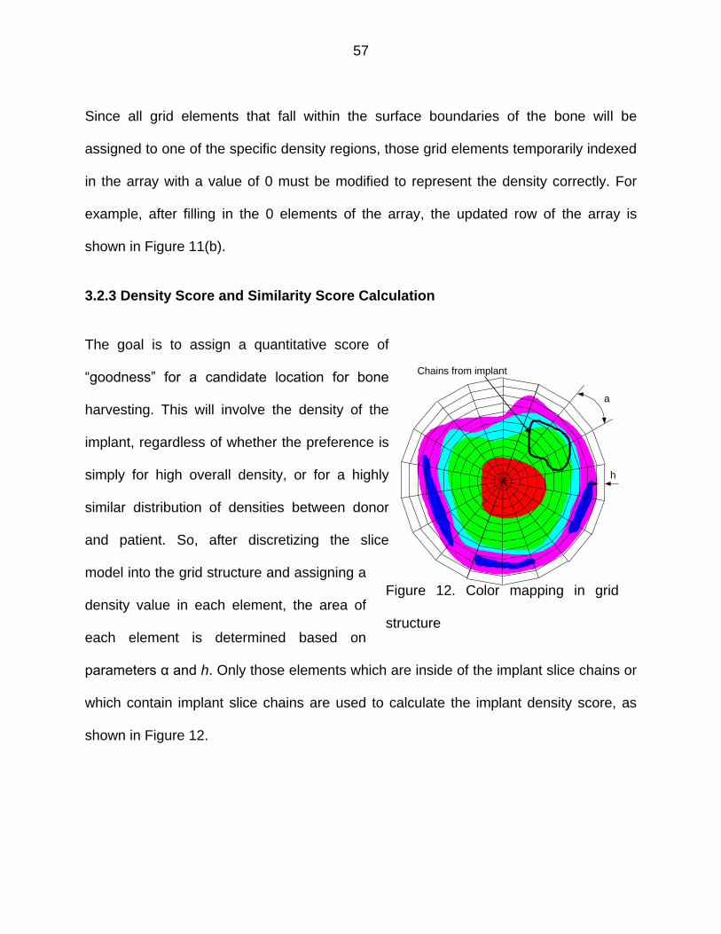
57
Since all grid elements that fall within the surface boundaries of the bone will be
assigned to one of the specific density regions, those grid elements temporarily indexed
in the array with a value of 0 must be modified to represent the density correctly. For
example, after filling in the 0 elements of the array, the updated row of the array is
shown in Figure 11(b).
3.2.3 Density Score and Similarity Score Calculation
The goal is to assign a quantitative score of
“goodness” for a candidate location for bone
harvesting. This will involve the density of the
implant, regardless of whether the preference is
simply for high overall density, or for a highly
similar distribution of densities between donor
and patient. So, after discretizing the slice
model into the grid structure and assigning a
density value in each element, the area of
each element is determined based on
parameters α and h. Only those elements which are inside of the implant slice chains or
which contain implant slice chains are used to calculate the implant density score, as
shown in Figure 12.
Figure 12. Color mapping in grid
structure
h
a
Chains from implant
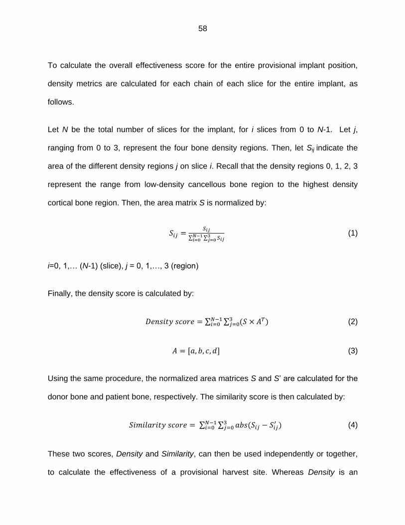
58
To calculate the overall effectiveness score for the entire provisional implant position,
density metrics are calculated for each chain of each slice for the entire implant, as
follows.
Let N be the total number of slices for the implant, for i slices from 0 to N-1. Let j,
ranging from 0 to 3, represent the four bone density regions. Then, let Sij indicate the
area of the different density regions j on slice i. Recall that the density regions 0, 1, 2, 3
represent the range from low-density cancellous bone region to the highest density
cortical bone region. Then, the area matrix S is normalized by:
∑ ∑
(1)
i=0, 1,… (N-1) (slice), j = 0, 1,…, 3 (region)
Finally, the density score is calculated by:
∑ ∑
(2)
(3)
Using the same procedure, the normalized area matrices S and S’ are calculated for the
donor bone and patient bone, respectively. The similarity score is then calculated by:
∑ ∑
(4)
These two scores, Density and Similarity, can then be used independently or together,
to calculate the effectiveness of a provisional harvest site. Whereas Density is an

59
aggregate score for the entire implant, Similarity is evaluated slice by slice. Hence,
although one could achieve a high overall Density score by having some portion of the
implant gain density at the expense of another portion losing density, the Similarity
score will be affected more locally.
Conceptually, the simplest approach is to conduct an exhaustive search of the entire
donor bone space to determine the optimal location for the harvested implant. This
exhaustive search involves rotating the implant about the Z-axis and translating the
implant up and down in the Z-axis direction, all while moving the implant closer to or
farther from the Z-axis radially. In other words, the implant is moved at the granularity of
the spider grid structure throughout the entire donor bone space. For each iteration, the
Density and Similarity are calculated, and then both values are normalized. In our
current implementation, a final attractiveness score is calculated based on a weighted
function of the aggregate “goodness” of each feasible solution.
(5)
Here and are coefficient weights on the importance of Density and Similarity; these
are values which can be assigned by the surgeon, radiologist, tissue bank technician,
etc.

60
3.3 Implementation Example
3.3.1 Matryoska Model Generation and Harvesting Search
The algorithms developed in this work have been implemented in C++ and are
graphically displayed using OpenGL. To illustrate the implementation of these analyses,
two sets of human tibia bone CT scan slices are used. These slices were first imported
into ITKsnap (open source software) and saved as a voxel array DICOM file. Next, the
DICOM data were loaded into Matlab, and the five Matyroshka shells were generated
using an increasing Hounsfield Unit cutoff. The created shells were then saved into a
PLY file in MATLAB, and imported to RapidForm software for post-processing. Post-
processing included correcting the geometric errors in the PLY file (holes, spikes, etc.).
The post-processed shells created were the marrow canal (Shell 1), one lower-density
cancellous bone (Shell 2), one higher-density cancellous bone (Shell 3), the cortical
bone shell (Shell 4) and the outer tibia surface (Shell 5), as shown in Figure 13, listed
with the respective HU used to generate them.
One set of the CT scan images had 566 slices, each of 228×264 voxels and within
spacing of 0.3 mm. The other set of data had 298 slices of 205×298 voxels, within
spacing of 0.5 mm. From each set of CT scan images, a polyhedral PLY file was
generated. These PLY files were subsequently used for harvesting analysis. Both
patient bone and donor bone models were sliced with 2.0 mm spacing. To create the
“spider,” discretization parameters α and h were chosen to be and 1.35 mm,

61
respectively. The overall Density score of the implant from within the original patient
bone was found to be 435.
(a) (b) (c) (d) (e)
Figure 13. A Matryoshka shell model of a human tibia. (a) Shell 1 (210HU); (b) Shell 2
(350HU); (c) Shell 3(HU500); (d) Shell 4(850HU); (5) Shell 5(1500HU).
It is worth noting that there are two goals in the implementation, or at least, two modes
of use envisioned. Although the methods in this paper allow direct investigation of the
total numerical scores and optimization, surgeons may in fact desire a tool to
manipulate implant sites by hand so as to receive a real-time score for each provisional
harvest position. Conceptually this would take the form of an “applause meter,” which
gives the surgeon feedback during manipulation of the implant in the design space.
Based on this second implementation concept, an initial interactive graphics software
interface has been developed (Figure 14). In this example, after aligning the ends of
patient bone and donor bone, the implant was translated into the donor bone, where the
initial Density score and Similarity score of the harvested implant in the donor bone
were found to be 339 HU and 1, respectively. In Figure 14(a), the black arrow pointing
to the left color bar shows the Density score of the implant in the original patient bone,

62
(a) (b)
Figure 14. Implementation results for two provisional implant harvest sites. (a) Initial
location of the implant within the donor bone; (b) The location of the implant is updated
by rotating about the Z-axis by , translating along the Z-axis direction by -4.0 mm,
and moving radially by 1.0 mm.
while the pink arrow pointing to the right color bar shows the Density score of the
harvested implant from within the donor bone. Likewise, the pink arrow pointing to the
right color bar represents the Similarity score (There is obviously no “original” similarity
to compare against). After rotating the implant about the Z-axis by , translating the
implant along the Z-axis direction by -4.0 mm, and moving the implant radially by 1.0
mm, the updated Density score and Similarity scores of the harvested implant in the
donor bone are 533 HU and 1, respectively. In Figure 14(b), we note that the pink arrow

63
pointing to the Density bar jumps above the black arrow, which denotes that the new
provisional harvested location has a higher Density score than the original implant
within the patient bone. In this case, the Similarity score remained essentially the same.
We envision a surgeon using an interactive tool to move the implant around the donor
bone and monitor the Density and Sensitivity bars to aid in finding a best site for
harvesting. The ideal for the allograft in most instances would be to replicate the normal
native local density distribution of bone at the recipient site. However, the program
would also allow the requesting surgeon to over-ride that default condition, by
prescribing a desired density distribution of his/her choosing as clinical indications
dictate. Under cursor control, the tissue bank operator would then provisionally position
the idealized allograft geometry at a plausibly acceptable location within the donor bone
geometry. Given the goodness-of-match between the provisional harvest and the
idealized allograft HU distributions, and given the degree of acceptability of the
structural stiffness of the corresponding provisional sacrificial supports, the overall
attractiveness of that provisional harvest position would then be quantitatively scored,
and feedback provided to the operator. The benefits of this new software, which would
be most helpful from the clinical perspective, would be both the user-friendly real-time
interface, as well as ability of the software to choose a best fit for both geometry and
density. Currently available software provides no basis (other than operator judgment)
for selecting the specific harvest site beyond ensuring that the implant object to be
machined lies entirely within the outer surface of the donor bone. The following presents

64
an implementation of an automated search for a harvest location using the developed
models.
To conduct an automated search for our implementation, we iterated through the design
space and recorded results for Density and Similarity. Through rotations of the implant
about the Z-axis by increments, translating the implant along the Z-axis direction in 2
mm increments, and moving the implant radially by 1.5 mm increments, we generated
the normalized Density score and Similarity score plots for several donor bones models.
As one example, Figure 15 shows a plot of Density scoring for one sample bone, where
maximal value is achieved at iteration 2575.
Figure 15. Plot of normalized Density score showing iterations about the axis, along the
axis and radially.
0 500 1000 1500 2000 2500 30000
0.2
0.4
0.6
0.8
1
Iteration
Norm
aliz
ed d
ensity s
core

65
3.3.2 Implant Harvesting Using CNC-RP
CNC-RP is a fully automated Subtractive Rapid Prototyping process that uses a 3-axis
vertical milling machine with a 4th axis indexer for multiple setup orientations [45]. In this
system, round stock material is fixed between two opposing chucks and rotated
between operations using the indexer, and visibility analysis of cross sectional slice data
provides a basis for automated setup planning about a single axis. This implementation
uses a modified Greedy set cover algorithm to determine orientations. For each
orientation, all visible surfaces are machined using simple layer-based toolpath planning
while leaving a structure of “sacrificial supports” that are used to fixture the part
(keeping the part attached to the remainder of the stock). The number of rotations
required to machine a model is dependent upon its geometric complexity. Once all of
the operations are complete, the supports are severed in a final series of operations,
and the part is removed. Figure 16 illustrates the process steps for creating a typical
complex part using this strategy.
The motivation for the Matryoshka model and harvesting search method has been to
determine a solution for optimal “harvesting” when using Subtractive Rapid Prototyping
(CNC-RP) for custom bone implants. To illustrate that the Matryoshka approach can be
used to plan harvesting locations for creating a custom bone implant from a donor bone,
an example of harvesting an implant using CNC-RP is demonstrated. The approach
starts with scanning a potted surrogate tibia bone, as shown in Figures 17(a) and 17(b).
In this instance, a laser scanner is used to create the outermost shell of the bone and
pot, and then a pre-existing set of Matryoshka shells from a representative human tibia
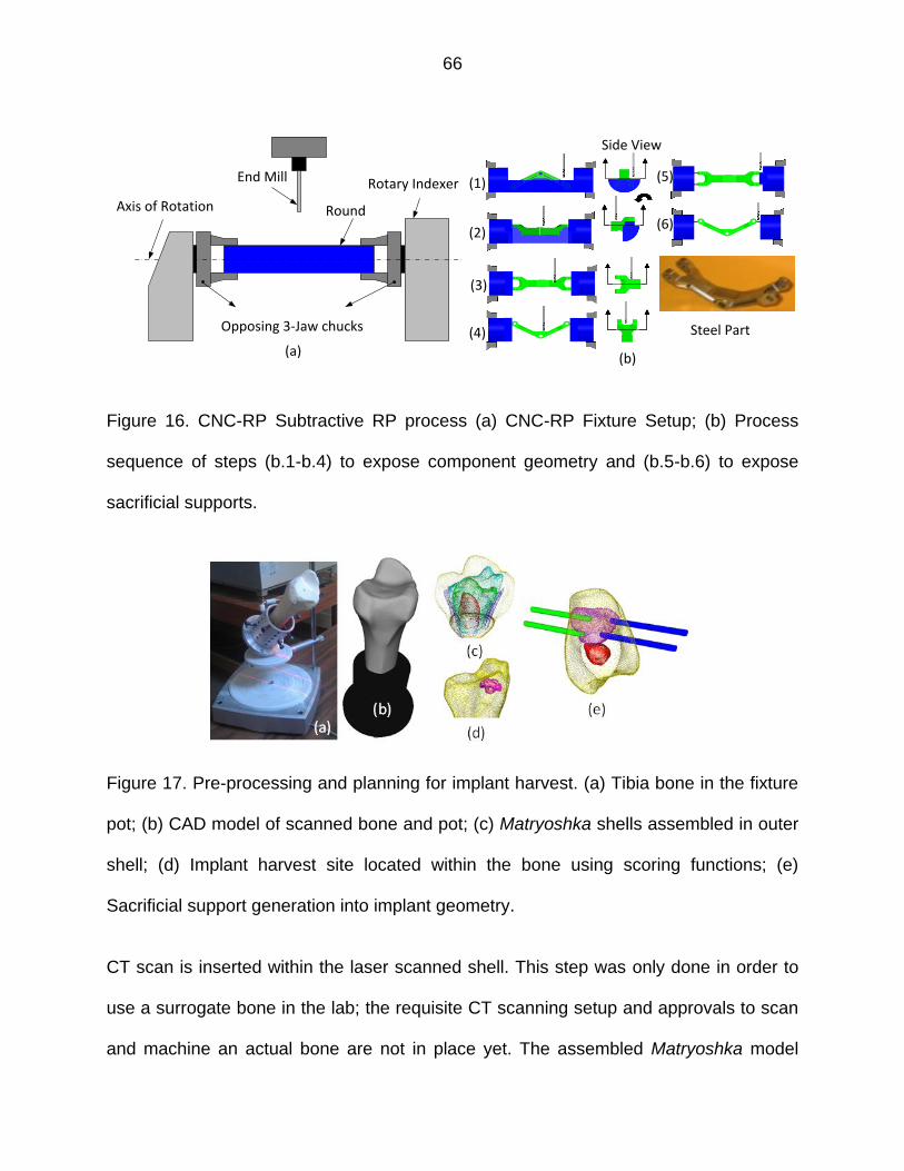
66
Opposing 3-Jaw chucks
Round
Rotary IndexerEnd Mill
Axis of Rotation
(Side View) (Side View)
Rotate StockRotate StockRotate Stock
Side View
Steel Part
(a) (b)
(1)
(2)
(3)
(4)
(5)
(6)
Figure 16. CNC-RP Subtractive RP process (a) CNC-RP Fixture Setup; (b) Process
sequence of steps (b.1-b.4) to expose component geometry and (b.5-b.6) to expose
sacrificial supports.
Figure 17. Pre-processing and planning for implant harvest. (a) Tibia bone in the fixture
pot; (b) CAD model of scanned bone and pot; (c) Matryoshka shells assembled in outer
shell; (d) Implant harvest site located within the bone using scoring functions; (e)
Sacrificial support generation into implant geometry.
CT scan is inserted within the laser scanned shell. This step was only done in order to
use a surrogate bone in the lab; the requisite CT scanning setup and approvals to scan
and machine an actual bone are not in place yet. The assembled Matryoshka model

67
(17(c)) was then used to find the best position and orientation within the donor bone
from which to harvest the implant, as shown in Figure 17(d) with inner shells hidden for
clarity. The locations for the sacrificial supports on the implant were then automatically
determined by the CNC-RP software, and are shown in Figure 17(e).
Next, a newly developed 5-axis device is used to allow the potted Tibia to be transferred
as “stock” material to the CNC-RP setup. Given an implant shape in its desired position
in the donor bone, the essential problem is to position the actual donor bone in such a
manner that sacrificial supports can be passed in appropriate orientations through the
donor bone, terminating at locations that will be just inside the to-be-harvested implant.
The setup used for this purpose is shown in Figure 18. In this system, the potted donor
bone is temporarily mounted to the rotary fixture and then rotated and translated to an
orientation and location between two disk templates - Figure 18(a). Then, a desired
number (minimum of two per disk) of the sacrificial supports can be passed through the
disks so as to intersect the desired implant surfaces and then the section of bone is
severed from the potted end - Figure 18(b). After drilling holes and embedding the
sacrificial supports (in this setup, stainless steel screws) to the necessary depths, the
bone, disks, and support units are removed en bloc from the fixture and mounted within
the 4-axis mill chucks. Finally, the implant geometry is revealed through layerbased
machining using CNC-RP developed process plans - Figure 18(c). The original implant
CAD model and machined implant with supports removed are shown in Figures 18(d)
and (e).

68
Figure 18. Implant harvesting using CNC-RP. (a) 5-axis positioning device places the
tibia bone surrogate between the disks; (b) Support-screw-affixed and then severed
section of the bone prepared for transfer to mill; (c) Nearly complete machined implant;
(d) Original implant CAD model; (e) Final implant with supports removed.
Complete processing of an implant can be done in a matter of hours. As presently
implemented, the harvest site search process takes approximately 20 minutes. The
SRP software requires approximately 15-30 minutes to automatically generate all
setups, supports, and toolpaths. Finally, the total processing time using CNC-RP is on
the order of a few hours. This overall time period is consistent with the goal of delivering
a custom implant within a few days of a traumatic incident; most surgeries for extreme
trauma involve waiting several days for physiologic stabilization, reduction in swelling,
etc.
3.4 Conclusion
This paper presents a new method for multi-material model representation using nested
polygonal shells, analogous to a Matryoshka doll. Compared with methods of hand-
creating an assembly model for input to a multi-material additive RP system, this

69
method could potentially be completely automated, given a set of parameters. This work
illustrates how the Matryoshka model can be used to plan harvesting locations for
creating custom bone implants from within actual human donor bones, and it develops
an approach to calculate a Density score and Similarity score for an arbitrary provisional
implant harvest site, to evaluate the overall effectiveness of that harvest site.
This approach to finding the optimal implant harvest site within a donor bone still leaves
room for improvement, and is not necessarily a generic solution for all multi-material
components. The method has, however, proven effective for human long bones, which
can be approximated by a cylinder model. In these bones, it is relatively easy to find the
center line, and it is reasonable to assume that the density of the long bone decreases
from the outer surface to the center line. Based on this assumption, the implant is
simply rotated around the center line. If the bone is not a long bone, and/or cannot be
approximated as a cylinder, one would need to allow the implant to “tumble” in 3D
space. Hence, an exhaustive search would probably not be tractable since the solution
space would be much larger. Future work with the Matryoshka approach could be used
to develop a better harvesting solution for irregular and/or flat bones. It could also be
used to pursue variants of the method for use in industrial components which may have
less amorphous shapes, and which could be printed using existing additive systems
such as LENS or polyjet printing.
3.5 Reference
[1] Kumar, V., Burns, D., Dutta, D. and Hoffmann, C., A framework for object modeling, Computer-Aided Design, 1999, 31(9), 541-556.

70
[2] Markworth, A.J., Ramesh, K.S. and Parks, W.P., Modeling studies applied to functionally graded materials, Journal of Materials Science, 1995, 30(9), 2183-2193.
[3] Kruth, J.P., Mercelis, P., Vaerenbergh, J.V., Froyen, L. and Rombouts, M., Binding mechanisms in selective laser sintering and selective laser melting, Rapid Prototyping Journal, 2005, 11(1), 26-36.
[4] Harrysson, O.L.A., CansiZoglu, O., Marcellin-Little, D.J., Cormier, D.R. and West, H.A., Direct meta lfabrication of titanium implants with tailored materials and mechanical properties using electron beam melting technology, Materials Science & Engineering.C, Biomimetic Materials, sensors and systems, 2008, 28(3), 366-373.
[5] Thomsen, P., Malmström, J., Emanuelsson, L., René, M. and Snis, A., Electron beam-melted, free-form fabricated titanium alloy implants: material surface characterization and early bone response in rabbits, Journal of Biomedical Materials Research Part B Applied Biomaterials, 2009, 90(1), 35-44.
[6] España, F.A., Balla, V.K., Bose, S. and Bandyopadhyay, A., Design and fabrication of CoCrMo alloy based novel structures for load bearing implants using laser engineered net shaping, Materials Science and Engineering: C, 2009, 30(1), 50-57.
[7] Bandyopadhyay, A., Krishna, B.V., Xue, W. and Bose, S., Application of Laser Engineered Net Shaping (LENS) to manufacture porous and functionally graded structures for load bearing implants, Journal of Materials Science: Materials in Medicine,2009, 20(1),29-34.
[8] Balla, V.K., Bodhak, S., Bose, S. and Bandyopadhyay, A., Porous tantalum structures for bone Implants: fabrication, mechanical and in vitro biological properties, Acta Biomater, 2010, 6(8), 3349-3359.
[9] Williams, C.B., Mistree, F.M. and Rosen, D.W., Investigation of solid freeform fabrication processes for the manufacture of parts with designed mesostructure, ASME IDETC Design for Manufacturing and the Life Cycle Conference,2005.
[10] Wang, H., Johnston, S.R. and Rosen, D.W., Design of a graded cellular structure for an acetabular hip replacement component, The Seventeenth Solid Freeform Fabrication Symposium, 2006, 111-123.
[11]Kou, X.Y.and Tan, S.T., Heterogeneous object modeling: a review, Computer-Aided Design, 2007, 39(4), 284-301.
[12] Chen, M. and Tucker, J.V., Constructive volume geometry, Computer Graphics Forum, 2000, 19(4), 281-293.

71
[13] Chandru, V., Manohar, S. and Prakash, C.E., Voxel-based modeling for layered manufacturing, Computer Graphics and Applications, IEEE, 1999, 15(6), 42-47.
[14] Jackson, T., Analysis of functionally graded material object representation methods, Ph.D. thesis. Massachusetts Institute of Technology, 2000.
[15] Shin, K.H. and Dutta, D, Constructive representation of heterogeneous objects, Journal of Computing and Information Science in Engineering, 2001, 1(3), 205-217.
[16] Zhu, F., Visualized CAD modeling and layered manufacturing modeling for components made of a multiphase perfect material, M.Phil. Thesis. The University of Hong Kong, 2004.
[17] Elishakoff, I., Gentilini, C. and Viola, E.,Three-dimensional analysis of an all-round clamped plate made of functionally graded materials, Acta Mechanica, 2005, 180(1-4), 21-36.
[18] Siu, Y.K. and Tan, S.T., Source‐based heterogeneous solid modeling,
Computer‐Aided Design, 2002, 34(1), 41-55.
[19] Biswas, A., Shapiro, V. and Tsukanov, I., Heterogeneous material modeling with distance fields, Computer Aided Geometric Design, 2004, 21(3), 215-242.
[20] Liu, H., Maekawa, T., Patrikalakis, N.M., Sachs, E.M. and Cho, W., Methods for feature-based design of heterogeneous solids, Computer-Aided Design, 2004, 36(12), 1141-1159.
[21] Samanta, K. and Koc, B., Feature-based design and material blending for freeform heterogeneous object modeling, Computer-Aided Design,2005, 37(3), 287-305.
[22] Qian, X. and Dutta, D., Design of heterogeneous turbine blade, Computer-Aided Design, 2003, 35(3), 319-329.
[23] Pasko, A., Adzhiev, V., Schmitt, B. and Schlick, C., Constructive hyper volume modeling, Graphical Models, 2001, 63(6), 413-442.
[24] Yao, J. and Taylor, R., Construction and simplification of bone density models, Proceedings of SPIE, 2001, 4322, 814-823.
[25] Bibb, R. and Sisias, G., Bone structure models using Stereolithography: a technical note, Rapid Prototyping Journal, 2002, 8(1), 25-29.
[26] Chen, Z.Z., Li, D.C., Lu, B.H., Tang, Y.P., Sun, M.L. and Wang, Z., Fabrication of artificial bioactive bone using rapid prototyping, Rapid Prototyping Journal, 2004, 10(5), 327-333.

72
[27] Fang, Z.-B., Starly, B., Shokoufandeh, A., Regli, W. and Sun, W., A computer-aided multi-scale modeling and direct fabrication of bone structure, Computer-Aided Design and Applications, 2005, 2(5), 627-634.
[28] Sun, W., Starly, B., Darling, A. and Gomez, C., Computer-aided tissue engineering: application to biomimetic modeling and design of tissue scaffolds, Biotechnology and Applied Biochemistry, 2004, 39(1), 49-58.
[29] http://academic.uofs.edu/faculty/kosmahle1/courses/pt245/trabecul.htm (accessed October 20th 2012).
[30] Nauth A, McKee M.D., Einhorn T.A., Watson J.T., Li R. and Schemitsch E.H., Managing bone defects, J Orthop Trauma, 2011, 25(8), 462-466.
[31] Bosse M.J., MacKenzie E.J., Kellam J.F., Burgess A.R., Webb L.X., Swiontkowski M.F., Sanders R.W., Jones A.L., McAndrew M.P., Patterson B.M., McCarthy M.L., Travison T.G. and Castillo R.C., An analysis of outcomes of reconstruction or amputation after leg-threatening injuries, New Engl J Med., 2002, 347(24),1924-1931.
[32] Vallier, H. A., Hennessey, T. A., Sontich, J. K., & Patterson, B. M., Failure of LCP condylar plate fixation in the distal part of the femur - A report of six cases. The Journal of Bone & Joint Surgery Case Connector, 2006, 88(4), 846-853.
[33] Skendzel, J. G., & Sekiya, J. K., Arthroscopic glenoid osteochondral allograft reconstruction without subscapularis takedown: technique and literature review. Arthroscopy: The Journal of Arthroscopic & Related Surgery, 2011, 27(1), 129-135.
[34] Clowers, B. E., and Myerson, M. S. (2011). A novel surgical technique for the management of massive osseous defects in the hindfoot with bulk allograft, Foot and ankle clinics, 2011, 16(1), 181-189.
[35] http://www.thefoxisblack.com/2009/12/07/matte‐black‐nesting‐dolls‐by‐muji/
(accessed September 1st 2012).
[36] http://geekopedia.blogspot.com/2009/04/munecas‐rusas.html
(accessed September 1st 2012).
[37] Frank, M.C., Hunt, C.V., Anderson, D.D., McKinley, T.O., and Brown, T.D., Rapid manufacturing in biomedical materials: using subtractive rapid prototyping for bone replacement, Proceedings of the Solid Freeform Fabrication Symposium, 2008, 686-696.

73
[38] Frank, M.C., Wysk, R.A. and Joshi, S.B., Determining setup orientations from the visibility of slice geometry for rapid CNC machining, Journal of Manufacturing Science and Engineering,2006, 128(1), 228-238.
[39] Li, Y. and Frank, M.C., Machinability analysis for 3-axis flat end milling, Journal of Manufacturing Science and Engineering, Transactions of the ASME, 2006, 128(2), 454-464.
[40] Li, Y. and Frank, M.C., Computing non-visibility of convex polygonal facets on the surface of a polyhedral CAD model, Computer-Aided Design, 2007, 39(9), 732-744.
[41] Frank, M.C., Implementing rapid prototyping using CNC machining (CNC-RP) through a CAD/CAM interface, Proceedings of the Solid Freeform Fabrication Symposium, 2007,112-123.
[42] Boonsuk, W. and Frank, M.C., Automated fixture design for a rapid machining process, Rapid Prototyping Journal, 2009, 15(2), 111-125.
[43] Petrzelka, E.J. and Frank, M.C., Advanced process planning for subtractive rapid prototyping, Rapid Prototyping Journal, 2010, 16(3), 216-224.
[44] Thomas T.P., Anderson, D.D., Willis, A,R,, Liu, P., Marsh, J,L, and Brown, T.D., Virtual pre-operative reconstruction planning for comminuted articular fractures, Clinical Biomechanics, 2011, 26(2), 109-115.
[45] Frank, M.C., Wysk, R.A., and Joshi, S.B., Rapid Planning for CNC Machining - A New Approach to Rapid Prototyping, Journal of Manufacturing Systems, SME, 2004, 23(3), 242-255.

74
CHAPTER 4. AUTOMATED FIXTURE DESIGN FOR THE SUBTRACTIVE RAPID
MACHINING OF HETEROGENEOUS MATERIALS: APPLICATIONS FOR NATURAL
BONE IMPLANT MANUFACTURING
A paper to be submitted to Rapid Prototyping Journal
Abstract
Purpose - The purpose of this paper is to present a new method for the automated
design of a fixturing system for the subtractive rapid machining of heterogeneous
materials, namely, natural bone implants.
Design/methodology/approach - The proposed method employs a method derived
from the idea of sacrificial supports in order to support a rapid machined bone implant
which is harvested within a donor bone. The parameters depth, diameter, and location
of the sacrificial supports depend on the different distributions of materials in the part.
During the machining process, the material around the embedded sacrificial supports is
machined, and at the end of the process, only the supports are connected to the part
and the remaining fixture disks.
Findings - The sacrificial support design approach provides a feasible solution for use
with heterogeneous materials for use in a subtractive rapid prototyping process.
Originality/Value – This work is the first to address a unique application of rapid
technologies for harvesting custom implants from donated allograft bone. It considers

75
the further challenge of dealing with a material density distribution across the interior of
the bone.
Keywords - Rapid prototyping, rapid manufacturing, automated fixturing, bone
implants.
4.1 Introduction
Fixtures are used to hold, secure and support a part in the correct orientation during a
manufacturing process. Traditional fixturing techniques use a number of workpiece
holding elements such as vises, clamps, V-block, modular plates, etc. depending on the
product variety and volume. Proper fixture design can dramatically reduce the
manufacturing cost, the labor skill requirements, etc. [1]. Over the past decades, fixture
design has garnered attention due to the extreme diversity and complexity of new part
designs [2]. Arguably, the best success story for automated fixturing is owed to the field
of Additive Manufacturing (AM), where sacrificial supports are automatically generated
very quickly and robustly; immediately prior to the start of processing [3].
Existing RP&M techniques actually fall into three categories: additive, subtractive or
hybrid additive/subtractive processes. In most current additive processes, the fixtures
used to hold the part are called sacrificial support structures, which are automatically
added during the building process for supporting the overhanging features of the part
and are then eliminated in the post-processing step. In general though, the idea of
sacrificial supports can be divided into two basic categories: passive sacrificial supports
and active sacrificial supports. Passive sacrificial supports are those that emerge on

76
their own, generally, in the form of un-fused powders, such as those found in Selective
Laser Sintering (SLS) and 3D Printing (3DP) [4, 5]. In other methods, the supports have
been actively designed as such, for example those used in Stereolithography (SLA),
and Fused Deposition Modeling (FDM) [6-9]. In either case, the supports are not really
designed by the user, generally, rather the process planning software handles their
design based on each unique part automatically.
Heterogeneous material, in general, refers to objects with spatially different material
compositions or structures [10, 11]. Heterogeneous objects are mainly classified into
two groups, multi-material objects, which have distinct material domains and functionally
graded materials (FGMs), which have continuous material variation in composition and
structure gradually over volume. Some existing additive manufacturing (AM) techniques
including 3D printing, Laser Engineered Net Shaping (LENS) and PolyJet Technologies,
can make parts with multiple materials, or at least designate multiple components in
color (3DP). In particular, the multi-material 3D printing system “Connex” developed by
Objet Ltd. has the capability of printing parts made from over a dozen materials [12] in a
single print. Though a wide range of homogeneous and heterogeneous material
mixtures have been employed in additive manufacturing, there is still a need for
developing additional materials [13, 14]. Moreover, many of the materials commonly
used in additive RP manufacturing processes such as resins and powders cannot be
used for fabricating truly functional models based on the designed part specifications
[3].

77
In order to improve the variety of materials available, Subtractive Rapid Prototyping has
been developed in an effort to produce functional prototypes using appropriate
materials, at least for a smaller subset of part geometries. CNC-RP is a subtractive
process that can create functional 3D parts from a wide variety of machinable materials
[15, 16]. As opposed to additive processes, the CNC-RP process involves sequentially
removing material (CNC machining) from bar stock to create complex geometric
shapes. Instead of adding support material as in AM, CNC-RP supports are created as
small features added to the solid model geometry (i.e. cylinders) and incrementally
created during the machining process along with other part features. When the
machining process is finished, only these sacrificial entities are connecting the part to
the stock material.
The machining setups for the CNC-RP process are shown in Figure 1. In this case, a
component is being machined using sacrificial supports to retain the part at its ends
along the axis of rotation. Four supports are used as shown in Figure 1(b), and 4
orientations are needed to machine the stock and create all the visible surface and
supports as shown in Figure 1(b.1-b.4). By the end of machining process, only two
permanent supports need to remain, as shown in Figure 1(b.5). Lastly, the part is cut
from the stock by sawing the two remaining supports, as shown in Figure 1(b.6). The
automated CNC-RP machining process as described above was originally developed
for making industrial parts from homogeneous materials, especially in solid metal.

78
(6)(2)
(4)
(3)
(1) (5)
Opposing 3-Jaw chucks
Round
Rotary IndexerEnd Mill
Axis of Rotation
(Side View) (Side View)
Rotate StockRotate StockRotate Stock
Side View
(7) Final Steel Part
(a) (b)
Figure 1. CNC-RP process. (a) Rotary fixture setup; (b) Process sequence of steps
(b.1-b.4) to expose component geometry and (b.5-b.6) to expose sacrificial supports.
However, if a part is to be made of heterogeneous
materials, it adds a significant new challenge for
support design. One particularly challenging
heterogeneous materials is natural bone, which has
a density distribution from inside to outside that
spans a significant range. To illustrate, Figure 2
shows a cross sectional view of a femur bone,
showing the spongy, low density trabecular bone in the middle, versus the high-density
cortical bone on the outside. Bone is a very important material for its use in
reconstructive surgery in the form of bone implants or grafts. Bone implants or grafts are
widely used in the treatment of missing pieces of bone in cases of trauma and other
bone loss. In order for the human body to accept the bone implant material and heal
properly, it is essential that the bone implant should be both mechanically and
biologically compatible. A surgical bone implant might call for a bone material density
Figure 2. A cross-sectional
view of a femur bone [17]
Cortical bone
Trabecular
bone

79
that is highly, or almost all cortical bone, or may call for some distribution of densities, or
simply try to match the general gradient directions in density of the surrounding bone. In
any case, there arises the challenge of having correctly shaped implants created from
appropriate material. A newly specialized variant of CNC-RP has been developed to
meet this unique challenge.
Figure 3 illustrates the machining setup with one axis of rotation used in the new CNC-
RPbio process. In this work, a “potted” bone is temporarily mounted to a rotary fixture
and then rotated and translated to an orientation and location between two fixture disk
templates (Figure 3a). The bone is potted, or fixture in a mechanical holding pot with a
set of compression screws in order to create a known coordinate system for an arbitrary
shape like a bone. Then, a number of sacrificial supports can be passed through the
disks so as to embed into the desired implant surfaces. Specifically, a set of surgical
screws are inserted through the disks into the bone, terminating where the implant will
exist upon completion. After screwing in the supports, the bone is cut along its shaft and
now can serve as the “stock material” (Figure 3b). The convenient advantage to this
method is that we go from a cumbersome bone shape that is a fixturing problem to a
section of bone between round fixture plates; essentially replicating what CNC-RP
typically uses - round bar stock between centers. All the rotations and translations of the
potted bone, drill locations and depths for the supports, and even the saw cut location
are provided in an automatically generated setup sheet. Once fixture between the disks,
the entire construct is moved from this offline fixture and mounted within the 4-axis mill
chucks. During the subsequent machining process, the stock is rotated several times

80
about the axis of rotation until all surfaces are completed machined, as shown in Figure
3(c). Finally, the supports are removed (Figure 3e) to release the custom machined
bone implant.
The CNC-RPbio machining process has the ability to calculate the visibility for polyhedral
CAD models to determine the machining rotation axis and then calculate the minimum
number of the setup orientations required to create the part about the rotation axis, as
was done in the past. One unique challenge is to develop algorithms for automated
support generation in this new application.
(a)
(b)
(c)
(d)(e)
Figure 3. Implant harvesting using CNC-RPbio. (a) 5-axis positioning device places a
potted tibia bone surrogate between the disks; (b) It is support-screw-affixed and then
severed section of the bone is prepared for transfer to mill; (c) Nearly complete
machined implant; (d) CAD model of the implant; (e) Final implant with supports
removed.

81
This paper presents an approach to determine a feasible layout of the sacrificial support
screws for a free-form shape part (bone implant) within a heterogeneous density
distribution (natural bone stock material and shape). The goal of this work is to
automatically generate an arbitrary free-form shaped object from within another arbitrary
free-form shaped stock object, where each has a unique material density distribution,
and to create these “parts” at the push of a button. If successful, we could enable the
cost effective manufacturing of bio-compatible implants that are custom shaped to the
unique needs of a patient, without the hand-sculpting of a surgeon.
4.2 Related Work
Fixture design techniques involve providing proper part orientation, location, support,
and clamping such that all the model features can ultimately be machined. Traditional
fixturing techniques using clamps, vices, V-blocks, modular plates, etc. have some
disadvantages such as reduced reachability for tools and increased process planning
and setup time. Therefore, improvement in fixturing and fixture design can result in
significantly improved accuracy of machined parts, time savings and other benefits. As
a result, great attention has been directed towards the development of flexible fixture
systems in the past decades [2, 18].
Since their inception in the 1980s rapid prototyping processes were intended to be
push-button, resulting in considerable research to address fixture designs in conjunction
with layer slicing and planning. For example, Ajay and Joneja [19] developed an
integrated software system called Quick turnaround cell (QTC) for rapid prototyping.

82
This fixture system was capable of machining prismatic parts but did not provide a
feasible fixture solution for arbitrary part shapes. Tseng proposed [20] a feature-based
fixturing analysis method to analyze the parameters required for the intermediate steps
in a successive feature-based machining process. The output of the fixturing
parameters included locating faces, clamping points and feasible height. However, the
shape of parts was restricted to prismatic or otherwise feature-based designs. Gandhi et
al. [21, 22] proposed a fluidized bed technique as a flexible fixturing process. It utilizes
materials that can change from a solid phase to a liquid phase and vice versa. When
the material is in the liquid state, the fixturing medium could accommodate a wide
variety of different part geometries. Choi [23] developed a reference-free part
encapsulation (RFPE) system that could fixture arbitrary geometric shapes during
machining. The basic concept involves filling the space around the part with low melting
point material, allowing to solidify, then machining, re-melting and re-orienting for the
next step, etc. After all machining was completed, the filler material is finally melted
away to reveal the finished part. Shin et al. [24] proposed a new type of technology
using a combination of high-speed machining technology and an automatic fixturing
process. It also used low-melting-point metal alloys to hold the workpiece during multi-
face machining. However, these processes cause thermal shrink and expansion
problems and were cumbersome to use. DeskProto sofrtware [25] uses a rotary axis
and support tabs to hold the part during the machining, somewhat similar to CNC-RP;
however, it does not provide analysis about the support design to determine if it is a
feasible solution for any arbitrary part. Roland [26] uses a similar fixture approach to
Deskproto, with support tabs that are added to the part, but it also does not give an

83
optimized or validated design to show the support works for any free-form parts.
Boonsuk et al. [27] developed an automated fixture design for CNC-RP, which includes
the design of sacrificial support length, shape, size, number, and location to minimize
allowable deflection of the part while maximizing machinable surface area. However, in
this sacrificial design, it assumes the part is made of one homogeneous material. The
automated support generation approach for mask image projection based additive
manufacturing developed by Zhou et al. [28] provided a scientific foundation for just
generating sufficient supports for arbitrary geometries. This method was incorporated by
EnvisionTec in its Perfactory RP software system [29]. Although numerous methods
have been investigated in the field of rapid technologies, there is no effective solution
for a subtractive rapid manufacturing process with heterogeneous materials in the
literature.
4.3 Overview of Sacrificial Support Generation for a Bone Implant
In this section, we provide an overview of designing the sacrificial support structure from
a set of nested STL shells, called the Matryoshka Model [30]. In this work a Matryoshka
shell model is used to describe density distribution of the bone. The Matryoshka model
is generated via an iterative process of thresholding the Hounsfield Unit (HU) data from
a computed tomography (CT) scan, thereby delineating regions of progressively
increasing bone density. An example of a Matryoshka model for the human tibia is
shown in Figure 4. This model was constructed of five shells: an innermost medullary
cavity shell (Shell 1), a low-density cancellous bone shell (Shell 2), a high-density
cancellous bone shell (Shell 3), a cortical bone shell (Shell 4), and a bone outer surface

84
(Shell 5). In this manner, the entire 3D volume of the bone is classified as being within
one of four bone regions, bounded by five shells. The thresholding HU used to generate
the shells will be discussed in the support layout section.
Shell 5Shell 4Shell 3Shell 2Shell 1 Assembled model
Figure 4. Matryoshka model of the human tibia. From left to right: five shells generated
from the medullary canal to outer bony surface, along with a cut-away view of an
assembled final model.
Next, a harvesting algorithm is used to identify the best location to create the implant
from within the tibia bone (donor bone), based on the given geometries and density
distributions. For example, a selected harvest location within a donor bone is illustrated
in Figure 5a. As discussed previously, after severing from the donor bone, only a bone
cut section serves as the “stock material” between fixture disks; which is clamped in the
CNC mill between rotary chucks. The rotation axis is already determined and all the
supports are parallel to the axis of rotation. One end of the supports will be embedded
into the stock (bone) and the other end of the supports is attached to the designed
fixture disk. The sacrificial supports are considered as new CAD features added to the
solid part model. Therefore, the process planning will include generating the tool paths

85
on the support features as well as the part model; making the cutting tool avoid collision
with the support screws.
Figure 5. (a) Sacrificial support generation into implant geometry; (b) Support design
parameters: depth (d1, d2, d3, d4), size (r1, r2, r3, r4), and location of supports.
Currently, surgical screws (titanium, stainless steel, bioabsorbable materials, etc) are
used for internal fixation of bones. In this work, stainless surgical screws are chosen as
sacrificial supports to provide fixation during the machining process. To place these
screws, the technician first drills screw holes in the bone to accommodate a screw for
rigid fixation. The propensity for crack initiation and propagation throughout the implant
generally increases due to the weakening of material around the screws during the
insertion. To reduce the stresses generated by the screw insertion, a proper size of drill
hole is needed; undersized drill bits from the manufacturers’ specifications are utilized.
The research challenge is to develop a method to automatically determine where, and
how deep and with what diameter screws should one fixture the implant. The objective
is to reduce the stresses from machining forces, while enabling complete geometry
86
creation, and limiting the depth with which the screw holes need to be drilled. The
design parameters of the support can therefore be summarized by depth, size, shape
and location (Figure 5(a)). These parameters are critical because the cutting force of the
machining process will result in a certain amount of VonMises stress in the bone
material. In addition to reducing stress, we also want to minimize the embedded support
depth within the implant. In this implementation, a safety factor of 2 is employed, such
that the VonMises stress must be less than 50 percent of the compressive strength of
the implant material [31, 32]. However, the design of each support parameter is not an
independent problem. For example, increasing the support diameter would reduce the
VonMises stress caused by the cutting force, but that would result in more surface
geometry on the part becoming non-machinable and leaving subsequently larger holes
in the implant. In this research, we use finite element analysis (FEA) to design and
optimize the support structure to meet those challenges. The following sections
describe the design of these support parameters.
Depth of the sacrificial support
During machining, the main strain caused by the cutting force is compressive strain.
When cutting forces are applied to the bone, it results in VonMises stress on the contact
surface between the surgical screws and the bone. The VonMises stress is expressed
as:
2 2 2
1 2 2 3 3 1( ) ( ) ( )
2VonMises
, (1)

87
2
2
1,22 2
x y x y
xy
, (2)
Where 1 , 2 , 3 are principal stress, xy
is the shear stress, and x ,
y are normal
stress in x and y direction, respectively.
The compressive strength is the capacity of a material or structure to withstand loads
tending to reduce size. The relationship between the ultimate strength and bone density
can be described as [33]:
20.06
c
c
S S
(3)
Where S is the compressive strength (MN/m2) of a bone specimen of apparent density ρ
(g/cm3) tested at a strain rate (loading rate) of (sec-1) and Sc is the compressive strength
of the bone with density ρc tested at a strain rate of 1.0 sec-1. Human compact bone
tested at a strain rate of 1.0 sec-1 has a compressive strength of 221 MN/m2 and a
density of approximately 1.8 g/cm3. Using these values, equation (3) is simplified to:
0.06
268S
(4)
Considering steel has a tensile strength range from approximately 300 MPa to more
than 1882 MPa, depending on the type of alloy. Since bone’s strength is significantly
less, it should be easier to machine than steel. The typical feedrate which is used to
machine aluminum and steel in the ISU lab is around 10ipm. For a conservative
approach, the same feedrate could be applied to the machining of human bone. Hence,

88
the loading rate of bone can be approximated to be 4.83 /sec-1. By substituting this
loading rate into equation (4), the bone ultimate strength equation can be expressed as:
274.7363S (5)
The bone density is in linear relationship with Hounsfield Unit (HU) data from a
computed tomography (CT) scan. It is assumed that the HU value for water is 0 and the
maximum bone HU value for the tibia bone model used in this paper is 1500. The
approximate maximal apparent density of bone is 2.0g/cm3. Thus, the bone density is
represented as:
2.01500
HU (6)
Obviously, the deeper the support screw is embedded, the larger the hole that will
remain after removal. Hence, selecting an optimal depth of the support needs to
consider both the density distribution of the part and the ultimate compressive strength
of the material; example given in Figure 6. The design of the supports shown on the
right side in Figure 6(a) are located in low-density cancellous bone regions based on the
consideration that the supports should go less deep into the bone implant (d2 and d4). In
Figure 6(b) the depth of supports 2 and 4 increase until they reach the high-density
cancellous bone region (d2 and d4). The support design in Figure 6(a) will result in small
holes in the implant compared with the support layout shown in Figure 6(b). However,
for the support layout shown in Figure 6(a), the material in low density cancellous bone
region usually has a low compressive strength. Therefore, if the VonMises stress at the

89
ends of the supports 2 and 4 is greater than the material compressive strength, the
supports could cause failure (cracking) of the bone material during machining.
Figure 6. Support design with small depth (a) and large depth (b).
Shape of the sacrificial support
Sacrificial supports could be created in any shape such
as circles, squares, ellipses, or rectangles. However, for
the convenience of drilling holes into the part, a
cylindrical shape is chosen in the current
implementation. In CNC-RPbio, the CAD model (STL file)
of the part is sliced into cross sections for analysis and
process planning. Since a slice file is used, the contour
of the slice is offset inwardly by more than the radius of the screws to provide a feasible
location to put the support center. Figure 7 shows the offset contour of an implant cross
sectional slice.
Figure 7. Offset contour.
Feasible region for locating
center of cylindrical support
Offset boundary

90
Number of sacrificial supports
The machinable surface area decreases as the number of sacrificial support increases,
since the presence of a support (surgical screw in this case) serve to obstruct access of
the machine tool to the implant surfaces. Hence, additional orientations could be
needed if the accessibility of the tool is blocked by additional supports. However, we
only use one screw on each end; for example, the part will undergo significant twisting
when the cutting force is applied. To simplify this problem, the support design used is
simply be 2:2 (#supports on each end along axis). Figure 8(a) shows tool accessibility
when two supports are used. The accessible angle (2θ) is expressed as:
1 2
2 2cos tD r
D
, (7)
Where, Dt is the diameter of the tool, D is the distance between the center of the two
supports on the end, and r is the radius of the supports. Consider D = k (Dt + 2r),
equation (7) becomes:
1 1
2 2cosk
, (8)
Since Dt and r are constants, when k increases, the distance between the center of the
two supports increases. From equation (8), when k increases, the accessible angle
increases. Figure 8(b) illustrates the relationship between k and accessible angle. From
Figure 8(b), we notice that when k increases from 1 to 2, the accessible angle increase

91
from 0o to 120o, therefore, the recommended distance between the center of the two
supports should be at least twice of Dt + 2r.
r
2θ
θ
Dr
Dr
Dcosθ
Figure 8. Accessible angle versus support distance [27].
Size of the sacrificial support
Since cylindrical supports are used in our research, the next step is to select the size
(diameter) of the screws. The design of the sacrificial support size is not an independent
problem, since other factors such as the support depth as well as the location of the
support will affect the VonMises stress caused by the cutting force. Determining support
size with other parameters gives a somewhat circular problem. For instance, increasing
the diameter of the support would reduce the VonMises stress, but increasing the
support diameter would change the feasible locations for the support. However,
changing the support location could also affect the VonMises stress. Therefore, to
simplify the design problem, it is assumed that the support diameter is determined
firstly, and then the depth and location are decided in a subsequent step.
1 2 3 4 5 60
50
100
150
k
accessib
le a
ngle
(degre
e)
Accessible angle
(a) (b)

92
Considering available tool sizes for drilling, we restricted support diameters to equal
multiples of 1/16 inch. The selection of the sacrificial support size is based on the worst-
case stress scenario, where we assume only one support is available, and then when
two can be placed, we have a safety factor in place. In a simple model of the conditions,
we consider the stock to be a simple cylinder, and the diameter of the cylinder is
computed from the minimum diameter of a cylinder that can enclose the bone cut
section along the axis. The cutting force is calculated from the power requirement of the
cutting tool generated by the material removal rate (MRR) and the unit horsepower [34,
35]. The approximated cutting force for aluminum and steel varies from 2 to 4.5 lbs [27].
Steel has a tensile strength range from around 300 MPa, up to more than 1882 MPa,
depending on the type of alloy [36]. Bone on the other hand, has an ultimate strength of
only around 298 MPa at most (From equation 5). Hence, the hardest cortical bone is still
easier to machine than steel. For a conservative estimate of average cutting force for
CNC-RPbio, a cutting force of 5 lbs is used for the worse-scenario analysis in this
research. Table 1 shows the VonMises stress of the contact surface between the
support (screw end) and the part. Our simulation results show the VonMises stress
dramatically increases when the support diameter decreases from 1/8 inch to 1/16 inch.
However, the ultimate compressive strength for the bone (cortical bone) is around 298
MPa (calculated from equation 5) which is less than the stress showing in Table 1 when
the support size is chosen to be 1/16 inch. Considering the size of expected clinical
bone implant (the minimal diameter of a cylinder that can enclose the implant would be
around 1~1.5 inch), 1/4 inch support diameter would result in a large amount of implant
surface becoming non-machinable, and large holes left after removing supports.

93
Therefore, 1/8 inch is chosen to be a suitable support diameter based on both the
consideration of bone compressive strength and implant size [37].
Table 1. FEA results with different support depth and diameter for the cylinder with 2
inch length and 2.5 inch diameter (FEA unit MPa)
Depth h (in.) 0 0.2 0.4 0.6 0.8 1.0 1.2
Diameter (in.) 1/16 587.9
570.7 570.6 585.3
559.4 544.9 557.1 564.8
578.0 576.5 556.9 557.9
509.6 488.3 502.2 517.3
591.5 569.6 559.8 589.1
602.3 601.2 628.0 619.7
570.8 573.0 551.0 570.9
1/8 72.72 73.56 73.46 70.18
68.41 67.45 66.59 67.07
59.33 63.36 64.36 61.29
59.37 63.75 66.30 62.41
61.34 62.11 64.94 64.51
71.49 73.60 72.04 66.64
63.29 64.95 67.61 62.14
1/4 7.134 7.318 7.364 7.578
7.894 7.769 7.413 7.293
6.627 7.391 7.674 7.028
7.886 7.979 8.109 8.741
7.767 7.670 7.654 7.440
8.040 7.593 8.031 7.801
8.113 8.882 7.825 7.602
Location of sacrificial support
The first step for determining locations for the screws are to calculate the diameter of
the cylinder that can enclose the cut bone section. According to that diameter, a stress
prediction function is chosen to estimate the VonMises stress. The second step is to
offset the slice contour of the part model inwardly or outwardly by more than the radius
of the screw. Recall that the Matryoshka shell model divides the 3D volume of the bone
into different regions, bounded by different shells. For the shells between the cancellous
and outer surface, the slice contours of the shells are offset outwardly by more than the
radius of the support radius. Then, a shell is selected to provide minimal thresholding

94
bone density value, and the location of the supports can only lie in the region where the
bone density is above the threshold value.
Figure 9 demonstrate the examples when different shells are selected to provide a
minimal HU thresholding value to enforce that support locations should be embedded
into specific regions and the corresponding support depth should be minimized
accordingly. In Figure 9(a), a medullary cavity shell (shell 1) is chosen as the boundary
so that two supports generated on the right side are slightly inserted into the bone
implant surface and embedded into the low-density cancellous bone region. In this
scenario, support depth d1=d2 = 0.2 inch. If a low-cancellous bone shell (shell 2) is
selected to be the boundary, the support will pass through the entire low-density
cancellous bone region and terminate in the high-density cancellous bone region, as
shown in Figure 9(b). To minimize the support depth, the depth of the screw penetration
into the high-density cancellous bone region is 0.2 inch.
Figure 9. Examples to minimize the support depth when different shells are selected to
be the HU thresholding boundary. (a) Medullary cavity shell (shell 1) chosen; (b) Low
density cancellous shell (shell 2) chosen.

95
To estimate the VonMises stress in the implant, we first assume the bone cut stock is
approximated as a cylinder, as shown in Figure 10(b). The radius of the cylinder is
calculated from the minimum radius cylinder that could contain the part. The support
locations within the cylinder can be represented by the coordinates (x1, y1, z1) and (x2,
y2, z2). We also assume the worst scenario that on one side of the cylinder stock there
is only one support located at the center of cylinder surface, and on the other side of the
cylinder two supports can be placed, shown in Figure 10(b). Since a cylinder is a
symmetric object about its center axis, the representation of the support location within
the cylinder can be simplified by five parameters. They are: the depths of supports 1
(h1) and 2 (h2) within the stock, the distance between the center of support 1 and
support 2 (D), the distance between the center of the support 1 to the center of rotation
axis (l1), and the distance between the center of the support 2 to the center of rotation
axis (l2), as shown in Figure 10(b) and (c). The function to estimate the VonMises stress
is expressed in the implicit function (9).
1 2 1 2( , , , , )Stress Func l l D h h (9)
h1
h2
Support 2
Support 1
Dl2
l1
(X2,Y2,Z2)
(X1,Y1,Z1)
d2
d1
(b)(a) (c)
Figure 10. Support layout. (a) Implant within bone cut stock; (b) Implant within cylinder
stock; (c) Cross section view of the stock.

96
To predicate the coefficients in the implicit function (9), a regression method is used to
estimate the VonMises stress of different combinations of l1,l2,D,h1,h2 for a two-support
layout from Finite Element Analysis (FEA). Two different regression methods, Kriging
approximation and multiple curvilinear regression methods are compared, in order to
better predict VonMises stress from the five variables.
Kriging is a method of interpolation that was originally developed in geostatistics by a
South African mining engineer [38]. The Kriging model has been used in a wide variety
of fields, including geological mapping, meteorology, climatology, and mechanical
engineering. It is also used to approximate the response of computer experiments,
especially when optimization problems require expensive simulations using finite
element methods (FEA) or computational fluid dynamics (CFD) [39].
The basic idea of Kriging is to predict the value of a function at a given point by
computing a weighted average of the known values of the function in the neighborhood
of the point. In order to construct a Kriging model, a spatial correlation function has to
be chosen. The correlation function could be Exponential, Gaussian, Linear, Cubic,
Spline or a Spherical function; depending on the property of physical model used. The
Gaussian function is the most commonly used in engineering design as it provides a
continuously differentiable surface, making it useful with gradient-based optimization
algorithm [40].
The mathematical form of a Kriging model has two parts, as shown in Equation (10).
( ) ( ) ( )y x f x Z x (10)

97
The first part is a deterministic contribution function f(x), which is usually represented by
a low order polynomial. The second part is a stochastic component Z(x), which is a
model of a Gaussian and stationary random process with zero mean and covariance:
2Cov[ ( ), ( )] = ( ( , ))i j i jZ x Z x R x x (11)
Where 2 is the process variance, is the correlation matrix and ( , )i jR x x is the
correlation function between data points ix and jx . We assume the VonMises stress
prediction function (9) is continuously differentiable, and a Gaussian function is chosen
as a correlation function. In this case, R is given by:
2m-
k=1
( , )= eji
k k kx xi jR x x
(12)
Figure 11(a) shows the residual plot using Kriging approximation for a given stock
cylinder of 2.5 inch diameter and 2.5 inch length. In this case, 231 data points are
random generated for analysis. The mean value and standard deviation of the residuals
are -0.13 MPa and 2.49 MPa, respectively. From Figure 11(a), one can see that the
residual varies from -9.93 MPa to 8.15 MPa. Figure 11(b) demonstrates the
corresponding residual plot using a multiple curvilinear regression method. The mean
value and standard deviation of the regression is -1.91e-011 MPa and 1.33 MPa,
respectively. The range of residual is from -3.63 MPa to 4.09 MPa, which is less than
the result from Kriging approximation method. Compared the residual plot from Kriging
approximation and multiple curvilinear regression method, the latter one has less

98
residual value, which indicates the multiple curvilinear regression general gives a better
VonMises stress predication then the Kriging approximation method in this case.
(a) (b)
Figure 11. Residual plot from Kriging approximation method and multiple curvilinear
regression method. (a) Kriging approximation: Mean = -0.13 MPa, std deviation = 2.49
MPa; (b) Multiple curvilinear regression; Mean = -1.91e-011 MPa, std deviation = 1.33
MPa.
Table 2 shows the regression analysis result when different orders of polynomial
functions are used. An RSquare value closer to 1 indicates a better fit to the data and a
smaller residual indicates a model is a much better predictor of the data. From the data
shown in Table 2, a fourth degree polynomial function is a better fit function than other
lower degree polynomial functions.
0 50 100 150 200 250-10
-5
0
5
10
Iteration
Resudal (M
pa)
0 50 100 150 200 250-10
-5
0
5
10
Iteration
Resudal (M
pa)

99
Table 2. Regression analysis for different orders of polynomial functions
Function degree
Summary of Fit Residual Analysis RSquare RSquare Adj Root Mean
Square Error Mean Std
Deviation
Quadratic 0.9327 0.9263 2.5666 0 2.4519
Cubic 0.9761 0.9689 1.6678 0 1.4621
Fourth degree 0.9802 0.9735 1.5398 0 1.3306
Based on the multiple curvilinear regression method, a 4-degree polynomial function is
proposed to predict the VonMises stress. For one setup rotation, there might be more
than one pair of supports locations available on each end. One example is shown in
Figure 12(a), which demonstrates there are four locations available for add the
sacrificial supports. After applying the criteria that the VonMises stress should be less
than the 50% of ultimate stress of the material, the number of available support
locations is reduced to three, shown in Figure 12(b). According to the constraint that the
center of the pair of supports should be at least twice of Dt + 2r, support r2 is excluded
from the layout and the final support location is r1 and r3 shown in Figure 12(c). In
general, the objective function of the support design is:
Objective Function: Minimize support depth (∑di).
Constraint 1: VonMises stress < 0.5(Compressive stress).
Constraint 2: Distance between two supports > 2(Dt + 2r).
Constraint 3: A shell is selected to provide minimal thresholding bone density value, and
the location of the supports can only lie in the region where the bone density is above
the threshold value.
Constraint 4: Maximize the distance between two supports.

100
Figure 12. Illustration of step to select the final sacrificial support layout.
4.4 Implementation Example
Matryoshka Model generation
The HUs used to generate the Matryoshka shell model can be determined by the
following procedures. We firstly assume a worse-scenario where only one support on
each side is possible; the support layout is 1:1. FEA is used to predict the VonMises
stress from the stock for a 1:1 support layout. The stock is approximated as a cylinder,
and the diameter of the stock varies from 1.5 inch to 2.5 inch and the length of the
cylinder ranges from 1.5 inch to 2.5 inch. The supports are located at the center of the
cylinder surface and embedded into the cylinder with different depth. The VonMises
stress from the FEA result ranges from 37.6 MPa to 73.56 MPa. The HU value obtained
after applying the equation (5) and (6) ranges from 531 to 744. For this scenario, if the
support layout is 1:1, the bone region that supports can be embedded into should have
HU value above 531 at least.
The other scenario is to assume two supports can be located on each side; the support
layout is 2:2. The supports are located far apart and are generally centered about the

101
axis of rotation from the part in process, and the supports are embedded into the
cylinder stock with different depth. The VonMises stress from the FEA result varies from
9.58 MPa to 16.44 MPa. After applying the equation (5) and (6), the HU value ranges
from 268 to 351. These two HU values indicate that if two supports are embedded into
the bone region, the HU value of that region should be at least 268.
In this implementation, HU values from 210 and 850 are used to generate a canal shell
and cortical bone shell for a given set of CT data. An HU value of 550 is used to create
another shell for a worse-scenario; wherein, if only one support on each side is
possible, then the support end can only be in the region outside of this shell.
Conversely, if two supports can be placed on each end, it is better that the support ends
should go to the bone region where the HU value is greater than 350. In summary, the
HU values used to generate Matryoshka shell models in this work are: 210, 350, 550,
and 850.
The algorithms developed in this work have been implemented in C++ within a
MasterCam CAD/CAM software add-on being developed - CNC-RPbio. Several bone
implant models have machined using the developed support design algorithms, as
illustrated in Figure 12. In order to mimic the multiple density shell regions of the
prototype bone surrogate, an Objet Connex 3D printer was used to additively
manufacture a multiple color plastic Matryoshka shell model of a human tibia (Figure 13
(a) and (b)).

102
The implant models shown in Figure 13 have a length of 1.14 in, width of 0.78 in, and
the thickness of 0.95 in. Figure 14(b) shows the assembled Matryoshka Model with the
harvested implant. Shell1 is selected as a boundary so that the supports can only lie in
the region between shell1 and outer surface. The compressive stress is set to be 50
MPa. The process planning starts with slicing the Matryoshka model and implant at 1.0
mm spacing. Each support is approximated as a cylinder and the support diameter is
chosen to be 1/8 inch.
Implant size: 1.14 x 0.78 x 0.95 inch
Support diameter: 1/8 inch
Left support location
Support 1: x: -1.49, y: 0.20, z: 0, depth d1: 0.24
Support 2: x: -1.34, y: 0, z: -0.40, depth d2: 0.24
Right support location
Support 3: x:-1.22, y: 0, z: 0, depth d3: 0.28
Support 4: x:-1.26, y: 0, z: -0.40, depth d4: 0.31
(a)
Implant size: 1.14 x 0.78 x 0.95 inch
Support diameter: 1/8 inch
Left support location
Support 3: x:-1.17, y: 0, z: 0, depth d3: 0.51
Support 4: x:-1.17, y: 0, z: -0.40, depth d4: 0.51
Right support location
Support 1: x: -1.20, y: 0, z: 0, depth d1: 0.24
Support 2: x: -1.32, y: 0, z: -0.40, depth d2: 0.24
(b)
Figure 13. Implementation examples using designed sacrificial supports in the
machining process.

103
d1d3
d2d4
Support1
Support2
Support3
Support4
(c)Shell1Shell1
Implant
(b)(a)
Figure 14. Support design
The process planning steps, including sacrificial supports, are automatically generated
within the MasterCam software add-on CNC-RPbio. Bone cut section rotations,
translations, drill support locations, depths, etc. are provided in a setup sheet from the
software. This setup sheet provides the detailed instructions required for machinists to
properly embed surgical screws into the bone. The machining tool paths for the bone
implant are generated based on the existing methods developed for CNC-RPbio, using
MasterCAM toolpath functions commanded by the add-on.
To evaluate the effectiveness of the support design method, the machined bone implant
was scanned to compare the different color surface areas between the initial implant
CAD model and the scanned model. The underlying assumption is that if the support
screw location was good, then one should expect the final implant to have the same
density distributions as originally planned; else, the bone shifted, bent or otherwise
moved under cutting conditions. The scanned implant model was imported into
Geomagics RapidForm software to create bounding lines for different color surface
regions. Figure 15 provides an example of a scanned color bone implant and Table 3

104
provides the surface area comparison results between the initial implant CAD model
and the resulting 3D scanned model. As can be seen, the area difference for different
color surface region is very small, which indicates the fixture system provides a robust
and accurate support location.
Figure 15. An example of 3D scan of color bone implant.
Table 3. Surface area comparison between initial implant CAD model and 3D scanned
model (Unit mm2).
Surface Initial CAD model Scanned model Difference % Difference
White 630 578 52 8.3%
Grey 337 329 8 2.4%
Black 628 745 117 18.6%
Total 1595 1652 57 3.6%
Next, the CAD model of machined implant with the support design was imported to
Abaqus to simulate the stress of the contact surface between the implant and
embedded screws. An example of the implant and supports CAD model is shown in
Figure 16. In this simulation, the largest expected cutting force is applied, and the
cutting force is applied tangentially through four different directions. Table 4 provides
the FEA result of predicted VonMises stress. From the result shown in table 4, the

105
maximal stress is 19.27 MPa, occurring at the contact surface between support 3 and
bone implant; which is less than the compressive strength of 50 MPa in the
implementation example.
Support 1
Support 2
Support 4
Support 3
Figure 16. CAD model of the implant with support design.
Table 4. FEA result of CAD model of the implant with support design (Unit MPa)
Support1 Support2 Support3 Support4
0 degree 0.97 6.74 1.89 19.00 90 degree 5.36 14.44 9.68 9.91
180 degree 7.34 6.81 19.27 3.63 270 degree 6.52 14.63 8.29 7.69
4.5 Conclusion
This paper presents a method for creating sacrificial support fixtures for the subtractive
rapid machining process of heterogeneous materials, namely, automated bone implant
manufacturing. The approach of fixture design has been shown to work well for several
surrogate bone implants machined in the laboratory. Compared with the traditional
hand-sculpting of bone implant by surgeons, this method provides the potential to
completely automate the process, and, should greatly improve the geometric accuracy
of the implants. The expectation is that a more accurate bone implant geometry will

106
yield better initial fixation stability and better overall outcomes. This includes better
alignment of the joints post-surgery, which can lead to reductions in osteoarthritis years
later. Being completely automated process planning should also make the process
affordable, even in the presence of custom fits for each and every new patient versus
mass production.
However, this approach still leaves room for improvement and refinement. In general,
the proposed solutions are largely predicated on the assumption of a general case of
sizes of implants and available surgical tools, it is not very generic. Future research
could analyze the parameters which can affect the stress generated by support insertion
process, using a much more general classification of screws and drills. Whereas the
resulting configuration suggests ~1/8 surgical screw, this is by no means an optimal size
for all implants in all cases. Work would need to consider a broader range, and show
how a continuous spectrum of design parameters, not just a discrete set of available off-
the-shelf surgical tools and fixators could be used. In order to evaluate the effectiveness
of the support design method, future work could measure the machined part to analyze
cracks, and estimate stress within the part, in addition to the surface geometry
comparison.
4.6 Reference
[1] Pehlivan, S. and Summers, J.D., A review of computer-aided fixture design with respect to information support requirements, International Journal of Production Research, 2008, 46(4), 929-947.

107
[2] Bi, Z. M. and Zhang, W.J., Flexible fixture design and automation: Review, issues and future direction, International Journal of Production Research, 2001, 39(13), 2867-2894.
[3] Chua, C.K., Leong, K.F., and Lim, C.S., Rapid prototyping: principles and applications, World Scientific, 2010.
[4] Kruth ,J.P., Wang, X., Laoui ,T. and Froyen L., Lasers and materials in selective laser sintering, Assembly Automation, 2003, 23(4), 357-371.
[5] Sachs, E., Wylonis, E., Allen, S., Cima, M. and Guo, H., Production of injection molding tooling with conformal cooling channels using the three dimensional printing process, Polymer Engineering & Science, 2000, 40(5), 1232-1247.
[6] Huang, X., Ye, C., Wu, S., Guo, K. and Mo, J., Sloping wall structure support generation for fused deposition modeling, The International Journal of Advanced Manufacturing Technology, 2009, 42(11-12), 1074-1081.
[7] Ziemian, C. W. and Crawn III, P. M., Computer aided decision support for fused deposition modeling, Rapid Prototyping Journal, 2001, 7(3), 138-147.
[8] Strano, G., Hao, L., Everson, R. M. and Evans, K. E., A new approach to the design and optimisation of support structures in additive manufacturing, The International Journal of Advanced Manufacturing Technology, 2013, 66(9-12), 1247-1254.
[9] Giannatsis, J. and Dedoussis , V., Decision support tool for selecting fabrication parameters in stereolithography, The International Journal of Advanced Manufacturing Technology, 2007, 33(7-8), 706-718.
[10] Sun, W., Multi-volume CAD modeling for heterogeneous object design and fabrication, Journal of Computer Science and Technology, 2000, 15(1), 27-36.
[11] Chen, K. Z. and Feng, X. A., CAD modeling for the components made of multi heterogeneous materials and smart materials, Computer-Aided Design, 2004, 36(1), 51-63.
[12]http://www.stratasys.com/3d-printers/design-series/precision/objet-connex500 (accessed April 3rd 2013).
[13] Hague, R., Mansour, S. and Saleh, N., Material and design considerations for rapid manufacturing, International Journal of Production Research, 2004, 42(22), 4691-4708.
[14] Hao, L., New material development for laser additive manufacturing, Proceedings of the 5th International Conference on Advanced Research in Virtual and Rapid Prototyping, 2011, 359-364.

108
[15] Frank, M.C., Wysk, R. A. and Joshi, S. B., Rapid planning for CNC milling - a new approach for rapid prototyping, Journal of Manufacturing Systems, 2004, 23(3), 242-255.
[16] Frank, M.C., Hunt, C.V., Anderson, D.D, Mckinley, T.O. and Brown, T.D., Rapid manufacturing in biomedical materials: using subtractive rapid prototyping for bone replacement, Proceedings of the Solid Freeform Fabrication Symposium, 2008, 686-696.
[17]http://academic.uofs.edu/faculty/kosmahle1/courses/pt245/trabecul.htm (accessed October 20th 2012).
[18] Kang, X and Peng, Q., Fixture feasibility: methods and techniques for fixture planning, Computer Aided Design and Applications, 2008, 5(1-4), 424-433.
[19] Joneja, A and Chang, T.C., Setup and fixture planning in automated process planning systems, IIE Transactions, 1999, 31(7), 653-665.
[20] Tseng, Y.J., Fixturing design analysis for successive feature-based machining, Computers in Industry, 1999, 38(3), 249-262.
[21] Gandhi, M.V. and Thompson, B.S., Phase change fixturing for flexible manufacturing systems, Journal of Manufacturing Systems, 1985, 4(1), 29-39.
[22] Gandhi, M.V., Thompson, B.S. and Maas, D.J., Adaptable fixture design: an analytical and experimental study of fluidized-bed fixturing, Journal of Mechanisms Transmissions and Automation in Design, 1986, 108(1), 15-21.
[23] Choi D.S., Lee S.H., Shin B.S., Whang K.H., Yoon K.K. and Sarma, S.E., A new rapid prototyping system using universal automated fixturing with feature-based CAD/CAM, Journal of Materials Processing Technology, 2001, 113(1), 285-290.
[24] Shin, B.S, Yang, D.Y., Choi, D.S., Lee, E.S. Je, T.J. and Whang, K.H., A new rapid manufacturing process for multi-face high-speed machining, The International Journal of Advanced Manufacturing Technology, 2003, 22(1-2),68-74.
[25] http://www.deskproto.com/support/videos-venus.htm (accessed April 3rd 2013).
[26] http://www.rolanddga.com/products/milling/mdx540/#overview (accessed April 3rd 2013).
[27] Boonsuk, W and Frank, M.C., Automated fixture design for a rapid machining process, Rapid Prototyping Journal, 2009, 15(2), 111-125.

109
[28] Chen, Y., A Contour-based Support Generation Method for Solid Freeform Fabrication of Complex Parts. Proceedings of the Solid Freeform Fabrication Symposium, 2009.
[29] http://digfablab.wikispaces.com/Envisiontec+Perfactory+RP (accessed April 3rd 2013).
[30] Lei, S., Frank, M.C., Anderson, D.D, and Brown, T.D. A method to represent heterogeneous materials for rapid prorotyping – the Matryoshka approach. Rapid Prototyping Journal, 2014, 20(5), Accepted.
[31] Biewener, A.A., Safety factors in bone strength. Calcif Tissue Int, 1993,53(1),68-74.
[32] Frost, H. M., On the strength-safety factor (SSF) for load-bearing skeletal organs, J Musculoskelet Neuronal Interact, 2003, 3(2), 136-140.
[33] Carter, D.R. and Hayes, W.C. Bone compressive strength: the influence of density and strain rate. Science, 1976, 194(4270), 1164-1176.
[34] Scheider, R., “Start with the right speeds and feeds”, MMS online, available at: http://www.mmsonline.com/articles/start-with-the-right-speeds-and-feeds (accessed Jan 20th 2013).
[35] Spitler, D., Lantrip, J., Nee, J.G. and Smith, D.A., Fundamentals of tool design, Society of Manufacturing Engineers, 2003.
[36]http://www.efunda.com/materials/alloys/alloy_home/steels_properties.cfm(accessed June 30th 2014).
[37] Farmanullah, K. M. and Awais , S. M., Evaluation of management of tibial non-union defect with Ilizarov fixator, J Ayub Med Coll Abbottabad ,2007, 19(3), 35-36.
[38] Krige D. A statistical approach to some basic mine valuation problems on the Witwatersrand. Journal of the Chemical, Metallurgical and Mining Society of South Africa, 1951, 52, 119-139.
[39] Kok, S., The asymptotic behaviour of the maximum likelihood function of kriging approximations using the Gaussian correlation function. EngOpt 2012 - International Conference on Engineering Optimization, Anonymous Rio de Janeiro, 2012.
[40] Martin, J. D. and Simpson, T. W., On the use of kriging models to approximate deterministic computer models. In ASME 2004 International Design Engineering Technical Conferences and Computers and Information in Engineering Conference, 2004.

110
CHAPTER 5: CONCLUSION AND FUTURE WORK
The chapter summarizes this dissertation and provides some ideas for future work.
5.1 Summary
This dissertation proposed a subtractive rapid manufacturing process for heterogeneous
materials, in particular for custom shaped bone implants. This includes two major areas
of research that will enable automated process planning of this new process. The
methodologies proposed in this dissertation have been implemented in a process
planning software, called CNC-RPbio. Several bone implants have been machined using
this software, and the results show the methodologies provide an effective and robust
process planning for the rapid manufacturing of bone implants from natural bone.
Firstly, a new method for multi-material model representation using nested polygonal
shells, called the Matryoshka shell model, was presented. This model is based on the
varying density distribution of human bone. The Matryoshka model is generated via an
iterative process of thresholding the Hounsfield Unit (HU) data from a computed
tomography (CT) scan, thereby delineating regions of progressively increasing bone
density. The method of choosing a suitable number of shells and the thresholding HU
value for generating each shell were also illustrated. Compared with the method of
hand-creating an assembly model for input to a multi-material additive RP system, this
method could potentially be completely automated from a given set of parameters.

111
Next, a harvesting algorithm was proposed, which could determine a suitable location
for the bone implant from within natural bone based on the Matryoshka model. In this
harvesting algorithm, a density score and similarity score are calculated to evaluate the
overall effectiveness of that harvest site. An interactive graphics program has been
developed based on this harvest algorithm. The software allows the user to move the
implant CAD model within the bone design space and observe the density score and
similarity score of the implant at candidate harvesting locations. The benefits of this
software would be most helpful from the clinical perspective. The surgeon can use this
software to choose a best fit for both geometry and density. However, the Matryoshka
shell model is not a generic solution for all multi-material components; it is most
effective for human long bones. If the desired donor bone is not a long bone, future
work with the Matryoshka approach would need to develop a better harvesting solution
for irregular and/or flat bones.
The second research area was to develop an automated fixturing system for securing
the bone implant during the machining process. During the machining process, the
material around the embedded sacrificial supports are machined, and at the end of the
process, only the supports are connected to the part and the remaining designed fixture
disks. The proposed method uses a variant of sacrificial supports (stainless surgical
screws, etc.) to pass in appropriate orientations through the free-form shaped stock,
terminating at proper locations inside the solid part model of the implant. The
parameters required for this design are the depth, diameter, and location of the
sacrificial supports, and are dependent on the density distribution of the part material.

112
Based on these design parameters, an objective function, which minimizes the
imbedded support depth with certain constraints, was proposed to determine the
optimal location of the supports termination inside the bone implant. This automated
fixturing system has been applied to machine several bone implants made of
assembled colored-RP models, where the final machined implants show the designed
fixturing system successfully provides stiffness to the part to enable accurate
machining.
Finally, the algorithms that were developed for setup planning are implemented in a
CAD/CAM software add-on called “CNC-RPbio”. This software can automatically
determine process planning parameters, such as choosing the optimal rotation axis of
the CAD model and creating the sacrificial support structures on each end of the CAD
model automatically. Several complex implant parts were machined using this software.
The result shows this software can be used as an automated process planning tool for
the rapid machining of custom shaped bone implants, which could create unique
implants at the touch of a button.
One future direction would be to improve the harvest search algorithm to find the
optimal implant harvest site for irregular and/or flat bones. Another future work should
explore utilizing the Matryoshka model and automated fixturing design to determine a
suitable axis of rotation for automated rapid machining of natural bone implants.

113
5.2 Future Work
5.2.1 Improving the Harvest Search Algorithm
The approach presented in this research to find the optimal implant harvest site within a
donor bone is not necessarily a generic solution for all natural bones. It is intended for
human long bones, since long bones can be approximated as a cylinder model and it is
relatively easy to find the center line of the bone (Figure 1(a) and (b)). In addition, a long
bone generally exhibits increasing density as one moves away from the bone center line
radially (Figure 1(c)). A proposed harvest search approach would be to find the gradient
direction that corresponds to bone density increase for irregular and/or flat bones
bones, and then by comparing or matching the density gradient direction of the donor
bone and the implant, an optimal implant harvest site location could be obtained.
Center
line
(a) (b) (c) (d)
Increasing density gradient
directions
Figure 1. Illustration of harvesting an implant from a donor bone. (a) A selected harvest
location within the donor bone; (b) A cylinder approximation of donor bone; (c)
increasing density gradient directions for the donor bone (c) and the implant (d).

114
5.2.2 Rotation Axis Selection
In this dissertation, we have presented two major areas of research what will enable
automated process planning for a rapid manufacturing of heterogeneous materials,
applied to natural bone implant manufacturing. The areas are using the Matryoshka
shell model to represent the heterogeneous material and the automated fixture design
methods. However, a rotation axis needs to be determined before applying the fixture
design.
An algorithm that can determine a suitable rotation axis for bone implant machining can
be developed based on the results from Matryoshka shell model and fixture design.
Some of the factors that are included in this algorithm could be the percentage of
visibility of the implant model, feasible locations for the sacrificial supports, and the non-
machinable region blocked by the imbedded sacrificial supports.
Discretization of a sphere
A proposed first step might be to discretize the unit sphere into a grid of discrete points,
as shown in Figure 2. The axes of rotation are represented to connect the center point
O of the sphere with the discrete points on the sphere surface. The number of points on
the sphere is:
Num (points/axes) = M×N, where M = integer (
) and N = integer (
)

115
X
Y
Z
Rotation axis i
a
b
Figure 2. Discretization of a sphere
Visibility calculation
For each given rotation axis i, the visibility percent of the model would need to be
calculated. For each segment on the slice model, one would check if the segment is
visible or non-visible. The precedure to check the visibility can be classified into two
steps: (1) checking the visibility of the segment with respect to other segments on the
same chain and; (2) checking the visibility of the segment with respect to other
segments on other chains but within the same slice. If both the result from the two steps
gives the result that the segment is visible, we can define the segment is visible.
Non-machinable region blocked by the imbeded sacrificial supports
For each given rotation axis i, sacrificial supports are generated based on the fxiture
design approach presented in Chapter 4. However, the amount of non-machinable
surface area depends on not only the increasing size of the support but also the
geometry of the surface that the support is attached to. To illustrate this effect, an
example of an implant with supports is demonstrated in Figure 3. The precedure to
identify non-machinable region follows two steps: (1) identifying the implant chain

116
segments within the support chains and; (2) Identifying the non-visibility segments of the
unioned chains between the implant chains and the support chains. The result from the
two steps give the overall non-machinable region blocked by the embedded sacrificial
supports.
Implant
Sacrificial
support
Slice 2
Slice
1
Support
2Support 1
Chain from
implant
Chain from
support1
Chain from
support2
Chain from
support1Chain from
implant
A
B
B
AD
C
(b)
(c)
(a)
Chain from
support2Set
1
CD
Union slice
Union slice
A
B
A
C
(d)
(e)
CD
B
D
Figure 3. Support location and Non-machinable segment
Figure 3(a) shows an implant with the desired sacrificial supports. The cross sectional
view of slices 1 and 2 are shown in Figure 3(b) and (c) respectively. The segments AB
and CD highlighed in red are the non-machinable segment blocked by the embedded
sacrificial supports, which will give the non-machinable analysis from step 1. Figures
3(d) and 2(e) illustrate the result after applying the union operation between implant
slices and support slices. The visibility analysis of the union slices will give the non-
machinable analysis from step 2.

117
Determination of the optimal rotation axis
The determination of the optimal rotation axis depends on three factors: the visibility
percentage of the model, non-machinable percentage of the model caused by the
embedded sacrificial supports, and the possiblity of adding a sacrificial support for the
rotation axis. A score could be used to describe the third factor quantitatively. Finally, an
optimal function which considers all three factors is proposed to evaluate the
“goodness” of each rotation axis.
Final score = visibility percentage + (1 - non machinable percentage)+
support score.
The set of future work proposed in this section would take the next major step toward a
nearly automated solution, from CT scan to final bone implant for surgery.
Automaticaly generation the axis orientation for the implant could better define
machinable solutions tha are more optimized for other parameters. Given the highly
traumatic cases involved with these implants, the time period is a matter of days
between CT scans and the final surgery; hence, more automation would be very
advantageous for sure. In closure, the methods of this dissertation will take us one large
step forward in the ability to make custom implants at the push of a button and more
importantly, to ultimately improve the outcome for patients suffering such terrible
injuries.

118
ACKNOWLEDGEMENTS
I would like to take this opportunity to express my gratitude and thanks to those who
helped me with various aspects of conducting research and writing this thesis. This
dissertation would not have been accomplished without their support.
First and foremost, I would like to express my deepest gratitude to my advisor Dr.Frank.
His professional knowledge guides me in all the time of research and writing of this
thesis. His continuous support helped me with the challenges that arouse during my
study and research. His kindness makes my work a pleasant experience. I could not
have imagined having a better advisor and mentor for my Ph.D study.
Next, I would like to express my sincere gratitude to my committee members Dr. Winer,
Dr. Peters, Dr. Jackman, and Dr. Rivero. I appreciate the great suggestion they gave for
the accomplishment of this dissertation.
Next, I thank Ashish Joshi, Niechen Chen, Guangyu Hou, Joshua Adams in the Rapid
Manufacturing and Prototyping Laboratory, for their help to me.
Last but not least, I owe the success of this thesis to my family for their love and
support. I realize how lucky I am to have such great parents who give me the best they
have for my life.