Embed Size (px)
Citation preview

Mälardalen University Press Licentiate ThesesNo. 199
PROCESS DEVELOPMENT FOR INVESTMENTCASTING OF THIN-WALLED COMPONENTS
MANUFACTURING OF LIGHT WEIGHT COMPONENTS
Mohsin Raza
2015
School of Innovation, Design and Engineering
Mälardalen University Press Licentiate ThesesNo. 199
PROCESS DEVELOPMENT FOR INVESTMENTCASTING OF THIN-WALLED COMPONENTS
MANUFACTURING OF LIGHT WEIGHT COMPONENTS
Mohsin Raza
2015
School of Innovation, Design and Engineering

Copyright © Mohsin Raza, 2015ISBN 978-91-7485-204-2ISSN 1651-9256Printed by Arkitektkopia, Västerås, Sweden
Abstract
Manufacturing processes are getting more and more complex with increasingdemands of advanced and light weight engineering components, especially inaerospace industry. The global requirements on lower fuel consumption andemissions are also increasing the demands in lowering weight of cast compo-nents. Ability to produce components in lower wall thickness will not only helpto reduce the cost of production but also help to improve the efficiency of engi-neering systems resulting in lower fuel consumption and lesser environmentalhazardous emissions. In order to produce thin-walled components, understand-ing of mechanism behind fluidity as it is affected by casting parameters is veryimportant. Similarly, for complex components study of solidification morphol-ogy and it’s effects on castability is important to understand.
The aim of this work has been to investigate casting of thin-walled test ge-ometries (≤ 2mm) in aero-space grades of alloys. The casting trials were per-formed to investigate the fluidity as a function of casting parameters and fillingsystem in thin-walled sections. Test geometries with different thickness werecast and evaluated in terms of filled area with respect to casting parameters, ı.e.casting temperature and shell preheat temperature. Different feeding systemswere investigated to evaluate effects of filling mode on castability. Similarlyfor complex components where geometries are very organic in shape, solidi-fication morphology effects the quality of castings. Process parameters, thateffect the solidification morphology were identified and evaluated. In order todevelop a relation between defect formation and process parameters, solidifica-tion behaviour was investigated using simulations and casting trials. Similarlythe effect of factors that influence grain structure and flow related defects werestudied.
It was observed that fluidity is affected by the mode of geometry fillingin investment casting process. The filling mode also have different effect ondefect formation. A top-gated configuration is strongly affected by casting pa-
i

ii
rameters where as a bottom-gated configuration is more stable and thus fluidityis not significantly affected by variation in casting parameters. Less porosityand flow-related defects were observed in the bottom-gated system as com-pared to top-gated system. In the study about casting defects as affected byprocess parameters, it was observed that shell thickness is important to avoidinterdendritic shrinkage. It was observed that the increased shell thickness in-duces a steeper thermal gradient which is essential in order to minimize thewidth of the mushy zone. It was also observed that a slower cooling rate alongwith a steeper thermal gradient at the metal-mould interface not only helps toavoid shrinkage porosity but also increases fill-ability in thinner sections.
The work presented here is focused on the optimization of process parame-ters, in order, for instance, to improve castability and reduce the casting defectsin investment casting process. The work, however, does not focus on externallyinfluencing the casting conditions or modifying the casting/manufacturing pro-cess. The future work towards PhD will be focused on externally improvingthe casting conditions and investigating other possible route of manufacturingfor thin, complex components.
To Jonathan A. Dantzig, a friend, a mentor.

Preface
Advance engineering systems require integrated, net-shape and light weightcastings. Similarly, in the aerospace industry, for example, attempts to im-prove fuel economy and to reduce the Co2 emissions also require light weightengines. Researchers have been investigating the casting and solidification pro-cess since the 40s, however there is still a lot to do in order to understand thecomplex solidification process, especially when it comes to casting of thin-walled sections. There is still a great need for developing new knowledge aboutthe solidification process in casting of thin sections, where process complexityincreases significantly.
Through the Innofacture program at Malardalens Hogskola, a research pro-gram was initiated to study castability of the light weight engineering compo-nents by investment casting which is a strategic technology used for manufac-turing of hot gas path components for jet engines and industrial gas turbines.The research work is designed to produce industrial demonstrations using theavailable scientific knowledge, implementing it in a new application, i.e. lightweight castings and producing new scientific knowledge for the thin-walledinvestment castings. The reserach work will also explore the possibilities touse other manufacturing methods for the production of light weight engineer-ing components. The research work in this program was collaborated withSwedish and European foundries, research institutions and aero and gas turbinemanufacturers. The work provided a unique opportunity to develop collabora-tion between academia and industry to run a program aiming at producing thinand light industrial components for direct applications.
Presented in this research thesis the work performed during the last twoyears. The successful implementation of the results has been witnessed by boththe academia and the industry. I would like to take the opportunity to thank allmy colleagues at Innofacture and TPC Components AB and other field work-ers, especially Roger Svenningsson at Swerea Swecast AB, who have given
v

vi
their time and expertise during our meetings and discussions. My gratefulthanks to Bjorn Fagerstrom, Anette Stromberg and Mark Irwin for their valu-able support through the years. I would also like to gratefully acknowledgeKnowledge Foundation for financing the research work. Many thanks to myparents and brothers for all the moral support and the amazing chances theyhave given me over the years. At the last and in particular i want to express mysincere gratitude to Asifa and Asad. Their faithful support and never-failingcare has been a great comfort and safety.
Mohsin RazaEskilstuna, May 22, 2015
Contents
I Thesis 3
1 Introduction 51.1 The investment casting process- a brief description . . . . . . 71.2 Background and motivation . . . . . . . . . . . . . . . . . . . 81.3 Problem description . . . . . . . . . . . . . . . . . . . . . . . 81.4 Outline of thesis . . . . . . . . . . . . . . . . . . . . . . . . . 10
2 Frame of reference 112.1 Fluidity- General considerations . . . . . . . . . . . . . . . . 11
2.1.1 Test Geometries for fluidity measurements . . . . . . 132.2 Parameters that influence fluidity in Investment Casting . . . . 17
2.2.1 Parameters related to the shell system . . . . . . . . . 172.2.2 Parameters related to pouring . . . . . . . . . . . . . 202.2.3 Parameters related to the cast metal . . . . . . . . . . 22
2.3 Solidification morphology and casting defects . . . . . . . . . 232.3.1 Solidification behaviour in complex geometries . . . . 23
2.4 Simulation of investment casting process General considerations 302.4.1 Shell properties for simulation work . . . . . . . . . . 302.4.2 Thermo-physical Properties . . . . . . . . . . . . . . 30
3 Methodology 353.1 Experimental Study 1 . . . . . . . . . . . . . . . . . . . . . . 36
3.1.1 Experimental procedure for cast-ability study . . . . . 363.2 Experimental Study 2 . . . . . . . . . . . . . . . . . . . . . . 39
3.2.1 Experimental procedure to evaluate effect of processparameters on casting defects . . . . . . . . . . . . . 39
vii

viii Contents
4 Results 454.1 Experimental Study 1 . . . . . . . . . . . . . . . . . . . . . . 45
4.1.1 Fluid behavior . . . . . . . . . . . . . . . . . . . . . 464.1.2 Effects of process parameters . . . . . . . . . . . . . 464.1.3 Porosity in thin sections . . . . . . . . . . . . . . . . 48
4.2 Experimental Study 2 . . . . . . . . . . . . . . . . . . . . . . 504.2.1 Effect of temperature on shrinkage and grain size . . . 514.2.2 Effect of insulation on porosity and grain size . . . . . 544.2.3 Effect of shell thickness on porosity and grain size . . 564.2.4 Effect of time to cast on Porosity . . . . . . . . . . . . 56
4.3 Verification of results by simulations . . . . . . . . . . . . . 574.4 Limitation of the experimental studies . . . . . . . . . . . . . 60
5 Discussion 615.1 Shortcomings and suggestions for future research . . . . . . . 64
6 Conclusions 656.1 Research contribution . . . . . . . . . . . . . . . . . . . . . . 666.2 Industrial implications . . . . . . . . . . . . . . . . . . . . . 676.3 Future research . . . . . . . . . . . . . . . . . . . . . . . . . 67
6.3.1 Additive Manufacturing (AM) processes . . . . . . . 676.3.2 Pressure die casting for Ni-base turbine components . 68
Bibliography 69
II Included Papers 75
7 Paper A:The effect of shell thickness on defect formation in investment castNi base alloys 777.1 Introduction . . . . . . . . . . . . . . . . . . . . . . . . . . . 797.2 Experimental work . . . . . . . . . . . . . . . . . . . . . . . 807.3 Results . . . . . . . . . . . . . . . . . . . . . . . . . . . . . . 827.4 Discussion . . . . . . . . . . . . . . . . . . . . . . . . . . . . 847.5 Conclusion . . . . . . . . . . . . . . . . . . . . . . . . . . . 85Bibliography . . . . . . . . . . . . . . . . . . . . . . . . . . . . . 86
Contents ix
8 Paper B:Experimental study of the filling of thin walled investment castingin 17-4PH stainless steel 898.1 Introduction . . . . . . . . . . . . . . . . . . . . . . . . . . . 918.2 Experimental work . . . . . . . . . . . . . . . . . . . . . . . 91
8.2.1 Geometry and gating system . . . . . . . . . . . . . . 928.2.2 Mould manufacturing . . . . . . . . . . . . . . . . . . 928.2.3 Cast alloy . . . . . . . . . . . . . . . . . . . . . . . . 938.2.4 Test plan for castability measurements . . . . . . . . . 93
8.3 Results . . . . . . . . . . . . . . . . . . . . . . . . . . . . . . 948.3.1 Fluid behaviour . . . . . . . . . . . . . . . . . . . . . 948.3.2 Effects of process parameters . . . . . . . . . . . . . 958.3.3 Porosity in thin sections . . . . . . . . . . . . . . . . 99
8.4 Discussion . . . . . . . . . . . . . . . . . . . . . . . . . . . . 1008.5 Conclusions . . . . . . . . . . . . . . . . . . . . . . . . . . . 102Bibliography . . . . . . . . . . . . . . . . . . . . . . . . . . . . . 103
9 Paper C:The effect of shell thickness, insulation and casting temperatureon defect formation during investment casting of Ni base turbineblades 1079.1 Introduction . . . . . . . . . . . . . . . . . . . . . . . . . . . 1099.2 Experimental work . . . . . . . . . . . . . . . . . . . . . . . 1129.3 Results . . . . . . . . . . . . . . . . . . . . . . . . . . . . . . 115
9.3.1 Effect of shell thickness on porosity and grain size . . 1159.3.2 Effect of temperature on shrinkage and grain size . . . 1179.3.3 Effect of insulation on porosity and grain size . . . . . 119
9.4 Discussion . . . . . . . . . . . . . . . . . . . . . . . . . . . . 1199.5 Conclusion . . . . . . . . . . . . . . . . . . . . . . . . . . . 120Bibliography . . . . . . . . . . . . . . . . . . . . . . . . . . . . . 121

List of papers 1
The effect of shell thickness on defect formation in investmentcast Ni-base alloysMohsin Raza, Mark Irwin and Bjorn FagerstromPresented at 61st Technical conference, Investment Casting Institute.
Author’s contribution Conception and design, data collection, analysis andinterpretation, writing the article.
Experimental study of the filling of thin-walled investmentCastings in 17-4PH stainless steelMohsin Raza, Roger Svenningsson and Mark IrwinProvisionally accepted by MaFE- Metallurgy and Foundry Engineering Journal
Author’s contribution Analysis and interpretation, writing the article.
The effect of shell thickness, insulation and casting temper-ature on defects formation during investment casting of Ni-base turbine bladesMohsin Raza, Mark Irwin and Bjon FagerstromResubmitted with revision at International Foundry Research Journal
Author’s contribution Conception and design, data collection, analysis andinterpretation, writing the article.
1Papers included in the thesis are in original submitted formate
1

I
Thesis
3

I
Thesis
3

Chapter 1
Introduction
Pouring molten metal into hollow cavities of desired shape and then allowingit to solidify is a manufacturing process that can be traced back thousands ofyears. The product from traditional method is usually rough product with sim-pler design. With increased complexity of the designs, the lost wax processwas introduced to handle casting of complex shapes. The lost wax process,also called investment casting process employ a wax mould around which theceramic shell is built. The wax is removed by burning the ceramic mould toget a net shape cavity inside ceramic mould. The molten metal in then pouredinto cavity to get complex shapes and designs. The investment casting processhas been an important method to produce components for aero-industry since50’s. It offers excellent tolerances and surface finish with freedom of designfor complex geometries.
With increasing demands of more intricate and light weight engineeringcomponents, especially in aerospace industry, complexity of manufacturingprocess is also raised. The global requirements on lower fuel consumption andemissions are increasing the demands in lowering weight of cast components.Ability to produce components in lower wall thickness will not only help toreduce the cost of production but also help to improve the efficiency of engi-neering systems resulting in lower fuel consumption and lesser environmentalhazardous emissions. In order to investigate castability of alloys in thin-walledgeometries, it is important to understand the mechanism behind fluidity. Flu-idity as an empirical concept used by foundrymen is ability of molten metal toflow and fill the details in the mould [1]. Fluidity measurements are not directlyreciprocal of viscosity and are not presented as unique property of certain alloy
5

6 Chapter 1. Introduction
composition but largely depends on the test-piece used to measure the fluid-ity length. The conventional test for fluidity measurement uses a spiral cavityin sand mould. The molten metal is then poured into spiral cavity which flowsinto spiral and stops at some length due to the solidification. The fluidity lengthis then measured from pouring point to the solidification stop point [2]. Thefluidity of molten metals depends upon number of materials properties. Someof the important properties are listed below [3].
• Temperature
• solidification mode
• Viscosity of melt
• Composition
• Rate of flow
• Thermal conductivity
• Heat of fusion
• Surface tension
The concepts of fluidity can be separated into two more definable aspectsi.e. flowability and fillability [1]. In foundry practice, flowability is a dynamiccriterion and defined as ability of molten metal to flow which usually dependson melt properties and cooling conditions, for example, composition of alloy,viscosity, heat transfer rate et cetera. Fillability on the other hand is a staticcriterion and depend on the surface tension between flowing liquid and adja-cent mould material [1], [4]. Flowability limits the fluidity when metal solidifyprematurely due to the heat and mass flow whereas fillability limits the fluid-ity when molten metal can not reach the fine details of mould due to lack ofrequired hydrostatic pressure to overcome surface tension.
Several parameters related to both shell system, pouring and alloy affectthe ability to fill a thin section. Capadona’s review on fluidity [1] describes theeffect of different foundry parameters on fluidity of metals. Increasing superheat, mould temperature or pressure head will improve fluidity [1]. Changesin alloy composition will also have impact on fluidity. Flow rate and shellpermeability is also important parameters. There are also other possibilitiesthat can improve fluidity. Vacuum-assisted casting is one method that has beenproven to be effective [5]. This method is used both for gravity and counter
1.1 The investment casting process- a brief description 7
gravity casting. Vibrating is yet one other method which improves fluidity dueto reported [6] increase in effective pressure head. Different shell systems alsoeffect the fluidity as in literature it is argued that a fused silica shell system isbetter than an zircon-alumino-silicate system [7].
1.1 The investment casting process- a brief descrip-tion
A general description of the investment casting process consists of followingsequence [8],
• First a metal die is manufactured, normally in aluminum, to outline thegeometry of the component. Thereafter the pattern is made by injectingliquid wax into the die.
• The desired numbers of patterns are assembled by attaching the patternsto the sprue, making a replica of the casting.
• Then a continuously dipping and stuccoing is performed until the desiredthickness of the shell is achieved. Different slurries and stuccoing ma-terial is used during this sequence controlling the properties of the shell.Also, in the prime layer, some additional element can be added to aidnucleation.
• Next step is to cure the shell. This is done after the wax is melted outfrom the tree in an autoclave to secure that all wax has been removedfrom the mould, which is subsequent cured to create a hard ceramic shell.
• The mould is preheated to 1000-1250 ◦C before pouring. Pouring ofsteel is normally done at extra high temperatures.
• After pouring and subsequent solidification and cooling, the shell andin-gate system is removed.
• Final castings are removed to be cleaned and in most cases also heattreated in various ways to obtain proper mechanical properties.

8 Chapter 1. Introduction
1.2 Background and motivation
In order to manufacture intricate and light weight engineering componentswhich usually have fine details, very high precession mechanizing and drillingis required. These additional processes not only increases the cost of compo-nents but also increases lead time for production. High demands of precisionand quality also increases the scrape rate in and thus further increasing pro-duction cost. In order to keep the cost down it is very important to producecomponents as net-shape as possible.
To produce these components in net-shape using investment casting re-quires very precise control on process parameters to control the castability ofthese components. In order to get a control on process parameters it is impor-tant to understand the effect of materials properties, process parameters andcasting conditions on the castability of complex products.
The aim of this work is to study the castability of thin-walled componentsin order to develop new knowledge about the effects of different parameterson the fluidity in terms of fillability and flow ability into thin complex mouldsystems.
1.3 Problem description
As the flow of metal is turbulent during top-gated filling, a solid film formsrapidly on the surface of flowing metal stream. Due to friction, the solidifiedfilm is pinned to the walls of the cavity while a new solid layer continues toform at the surface of flowing stream. The pinning effect causes splits at thesurface of flowing stream allowing the metal stream to flow only along thestrong chains of solid films. The liquid stream will keep flowing as long asvelocity of the liquid and pressure head is sufficient to break the surface film[6]. On the other hand if the pressure head is reduced, velocity is droppedsignificantly or back pressure from the mould cavity is high, the liquid flowwill slow down letting the solid film grow at the liquid front and against thewalls. Any available pressure then is borne by solid film, not the surface ofthe liquid. In order to enter the liquid metal into thin cavities during castingof thin-walled geometries, tension on the liquid front should be higher then thetensile strength of the film before the metal can burst through. If the pressure isnot enough and velocity is significantly dropped, the capillary repulsion in thethinner channel stops metal flow and divert it to the thicker areas where cap-illary repulsion is not high and thus stops the filling into thin-walled sections.
1.3 Problem description 9
In investment casting process, casting temperature, shell temperature, pressurehead and pouring rate are the significant parameters that influence the casta-bility into thin sections by effecting the solidification time, formation of solidsurface films, ability the break the surface films and effecting the back pressurefrom mould cavity.
Solidification morphology is another aspect that effects the quality of cast-ings into thin-walled sections. Casting parameters for example, thermal gradi-ent at mould metal interface, heat transfer rate and flow pattern inside the cavityeffects the solidification pattern inside mould cavity. Control of these param-eters is very important in order to avoid interdendritic shrinkage, gas porosity,grain structure and miss-runs.
In this research work, the parameters that effects the filling of thin-walledsections and the parameters that effects the quality of castings in thin-walledsection will be investigated. The aim of the work is to produce the scientificknowledge about castability of thin-walled section. The objective is to developmethods that will support manufacturing of thin-wall components in an indus-trial setting.
Research question 1:
How do the casting parameters influence fillability and flowability in thin-walled castings.
The effect of process parameters, for example, casting temperature, shellpreheat temperature, mode of filling the mould and temperature drop in theceramic shell during transportation on flowability and fillability. How mouldfilling is affected by the process parameters?
Research question 2:
(a) What are the significant casting parameters that influence shrinkage for-mation in thin-walled geometries.
(b) How does the casting parameters influence microstructure in thin-walledgeometries
The effect of process parameters on the microporosity, microstructure andsurface defects in thin-walled castings. How the quality of castings is affected
10 Chapter 1. Introduction
by casting conditions?
In order to investigate the above mentioned questions, two experimentalstudies were performed. The experimental study 1 focus on the effects of cast-ing parameters on the castability in thin-section and the experimental study2 focus on effects of controlled solidification on casting defects, especiallyshrinkage porosity and grain growth.
1.4 Outline of thesisIn first part, the introduction chapter introduces the investment casting process,the background of topic, the aim and objective of this work and the researchquestions. The chapter 2, presents the state of the art in the field of invest-ment casting of thin-walled sections. The chapter 3 presents the methodology,the out line of experimental studies, design of experiments and motivation forchoosing experimental methods for investigation. Chapter 4 describes the ob-servations during the experimental studies. In chapter 5, discussion about theresults has been made and in chapter 6, analysis of results from study is pre-sented. Chapter 7 briefly describes the work plan towards PhD.
Chapter 2
Frame of reference
2.1 Fluidity- General considerationsIn the casting process, it is very important to design a process that facilitatesthe filling of mould completely, rapidly and let it solidify as soon as possible.A practical term used in foundry to measure the ability to cast is fluidity. Infoundry the fluidity is measured by different ways and a common term fluiditylength is often used to describe the fluidity of melt. The concept of fluiditylength in foundry is not well defined and much debated which often depends onthe test method and configuration. From a foundrymans point of view, fluidityis an empirical concept that is defined as the ability of molten metal to flow andfill a mould,[1, 9]. By this definition, fluidity of the melt in a casting set-up isnot a reciprocal of viscosity as it is defined in physics [10].
In a conventional fluidity test molten metal is poured in a spiral sand mouldand the flow distance of molten metal is measured before it solidify inside thetest piece. The length of melt traveled inside spiral depends on great number ofmaterial properties for example superheat, metal head, and mould temperatureetc. Other types of test geometries are also reported in literature [1, 11, 12].These tests genrally have some limitations as they fail to define the ability ofmetal to fill thin-walled sections and fine details where surface tension is moredominant.
Therefore a separation of the overall term fluidity is made based on twodifferent aspects of fluidity, namely flowability and fillability [1]. Flowabilitydepends upon superheat, pressure head, velocity of melt, solidification mor-phology and heat transfer coefficient of the mould where as fillability depends
11

12 Chapter 2. Frame of reference
on surface tension, solidification morphology and relation between pressurehead and surface tension. Flowability and fillability both act together in thinwalled investment castings.
The term fluidity will be used as a term incorporating both flowability andfillability. Flowability and fillability will be used whenever a particular param-eter will have influence on either phenomenon. Some analytical expressionshave been derived for fluidity. Sin et al. [13] presented an analytical expres-sion of fluidity, based on the original work by Flemings et al. [11] as:
Lf =ρV0t(kHf + CpTs)
2h(Tc − TM )
[1 +
h
2[
πδX
V0CpKρ]
](2.1)
Where:ρ is the density of liquid,t is the thickness,V0 is the velocity of liquid at entrance to section,k is some critical fraction of solidified alloy,Hf is the enthalpy of fusion,CP is the specific heat of the liquid,TS is the superheat defined as (TC − TL),h is the heat transfer coefficient at the metal-mould interface,TM is the initial mould temperature,TC is the temperature of the liquid metal,δX is the length of choking zone in alloy solidification,k is the thermal conductivity of the mould,ρ is the density of the mould material,Cp is the specific heat of the mould material.
Equation 2.1 states that flowability is a function of properties related toboth the alloy and shell system. Flowability is also directly proportional to thethickness of the casting and the heat transfer coefficient. Also increasing theheat content of the alloy at the same time as improving the insulation of themould would increase flowability. It is important to note that the equation 2.1describes only fluidity length i.e. flowability and does not covers the parame-ters related to fillability, i.e. surface tension dependent.
Fillability is related to the ability to fill small cross sections or small fea-tures and is due to the difference in actual metal pressure and surface tensionof the metal. In literature [1] section thickness of 1.0 mm is mentioned as thethreshold when fillability becomes important. 2.5 mm section thickness hasalso been reported in literature [9] as limit below which, surface tension be-
2.1 Fluidity- General considerations 13
come important. Even though there is no exact limit when the influence ofsurface tension takes over, its importance increases as the section thicknessdecreases.
2.1.1 Test Geometries for fluidity measurementsThere are different types of test geometries used by other researchers as sum-marized by Capadona in his review [1]. The selection of test geometry forfluidity measurements depends upon the aspects of fluidity under considera-tion i.e. fillability , flow ability or both, alloy solidification morphology andcasting process. Different test geometries for measure fluidity are presented inthe literature. For flowability measurements usually spiral type test geometryis used as shown in figure 2.1 (b). For fillabiity measurements usually wedgetype of test geometry is used as shown in figure 2.7. Similarly selection ofgeometry varies with casting process. In investment casting process a step ge-ometry is used with different thickness at each step to measure both flowabilityand fillability. Test geometries also varies if the measurements are being takenfor product development process of a specific industrial component. In figure2.1 (a) is a test geometry showed for the aero industry. This casting geome-try resembles to a turbine blade and is designed to fulfil the requirements forboth fillability and flowability. The outer radius approaches zero and fulfils therequirements for fillability while the thicker middle section allows measure-ments for flowability. Other test geometries found in review by Capadona [1]are shown in figures 2.2,2.3,2.4,2.5,2.6 and 2.7.
Ordinary spiral, horizontal, or vertical plates have also been used for fluid-ity tests as shown in figure 2.1 (b). Special arrangements where melt is suckedup in a tube and then flow distance is measured is shown in figure 2.1 (c). Theliterature review presented in this thesis mainly covers the following aspects ofcastability of thin and complex components.
• Effects of casting parameters on fillability of thin sections
• Effects of casting parameters on defect formation in casting of thin andcomplex components.
• Simulation and modelling of thin walled casting processes.
The licentiate work mainly utilizes the parts of literature which focus oneffects of casting parameters on castability and defect formation in thin-walledcastings.

14 Chapter 2. Frame of reference
Figure 2.1: Illustrates some test geometries used in literature, (a) reproducedfrom [14], (b, c) [9]
Figure 2.2: Illustrates geometry used in by Prussin and fitterer
2.1 Fluidity- General considerations 15
Figure 2.3: Illustrates geometry used in by Krynitsky recommended by IBF
Figure 2.4: Illustrates geometry used in by Cooksey et. al.
Figure 2.5: Illustrates geometry used by Taylor, Flemings et. al. [11]

16 Chapter 2. Frame of reference
Figure 2.6: Illustrates geometry used by Walker [12].
Figure 2.7: Wedge-type fiiability test [1]
2.2 Parameters that influence fluidity in Investment Casting 17
2.2 Parameters that influence fluidity in InvestmentCasting
Different process variables that effect both fillability and flowability in invest-ment casting will follow the same classification as in [1] and are accordingto:
• The shell system
• The pouring conditions
• The cast metal
Several parameters related to the shell system can change the fluidity of themolten metal.
2.2.1 Parameters related to the shell systemMould temperature
As the fluidity length is dependent on heat flux from molten metal to mouldwhich is a function of temperature between metal and mould, an increase inmould temperature would be beneficial for extending fluid transport. As can beseen in equation 2.1 the fluidity length i.e. flowability is inversely proportionalto the difference in metal temperature (TC) and the temperature of the mould(TM ). However the increase in mould temperature does not significantly effectfillability [1]. In thicker geometries in which surface tension is not strong, atlower mould temperatures the heat is removed quickly because of the tempera-ture difference resulting in very rapid freezing and thus reducing flowability atlower mould temperatures. The flowability as effected by mould temperatureis well documented in literature. Researchers [12, 15] has observed an increasein fluidity length with an increase of mould temperature in an air cast thin bladelike geometry in austenetic stainless steel. However, insignificance of mouldtemperature in terms of fluidity has also been reported in literature [1]. Oliffet al. [15] also reported that effect of mould temperature becomes lesser whenthickness of sections is reduced, especially when the flow rate is low. Theinsignificant effect of mould temperature in thin-walled sections might be at-tributed to the fact that fillability is the controlling mechanism in thin sectionsand as back pressure exerted by surface tension flow rate is reduced. Anotherwork [14] reported that when casting a thin blade like geometry in a nickelbased alloy, the influence of the mould temperature on fluidity showed that the

18 Chapter 2. Frame of reference
fluidity decreases in the temperature interval 600-750 ◦C. A further increasein mould temperature increased the fluidity. However, the maximum temper-ature of the mould was 900 ◦C. Maguire et al. [16], performed experimentsto find effect of super-heating of the melt and mould temperature on the fillingbehaviour of investment casting thin plates in 17-4PH stainless steel, see figure2.8. They found that the mould temperature had no effect on the fluidity ofthe casting between 870-1150 ◦C, a practical temperature range for investmentcasting of stainless steel. They explain that this result probably was relatedto the in-gate dimension, which was held constant during all experiments at athickness of 1.5mm. However, they found that pouring temperature had signif-icant effect as when pouring at low temperature there was not sufficient heatleft in the metal to enter the in-gate and freezing began all ready at the in-gate.on the other hand as pouring temperature was increased the heat in the systemwas sufficient to enter the in-gate and mould filling was observed.
Figure 2.8: Illustrates geometry used in by Maguire et al.
Shell thickness
Chandraseckariah et al. [14] presented a study on effects of shell thicknesson fluidity in a blade like geometry, cast in nickel base alloy under vacuum inwhich observed a non linear relation between shell thickness and fluidity. Theyobserved decrease in the fluidity with an increase in shell thickness, however,with further increase of the mould thickness the fluidity increased again[14].The trend was same at different mould and pouring temperature at a vacuumlevel of 0.1 Torr.
2.2 Parameters that influence fluidity in Investment Casting 19
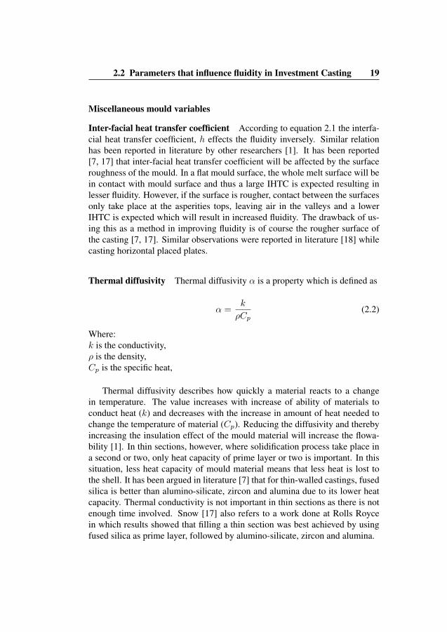
Miscellaneous mould variables
Inter-facial heat transfer coefficient According to equation 2.1 the interfa-cial heat transfer coefficient, h effects the fluidity inversely. Similar relationhas been reported in literature by other researchers [1]. It has been reported[7, 17] that inter-facial heat transfer coefficient will be affected by the surfaceroughness of the mould. In a flat mould surface, the whole melt surface will bein contact with mould surface and thus a large IHTC is expected resulting inlesser fluidity. However, if the surface is rougher, contact between the surfacesonly take place at the asperities tops, leaving air in the valleys and a lowerIHTC is expected which will result in increased fluidity. The drawback of us-ing this as a method in improving fluidity is of course the rougher surface ofthe casting [7, 17]. Similar observations were reported in literature [18] whilecasting horizontal placed plates.
Thermal diffusivity Thermal diffusivity α is a property which is defined as
α =k
ρCp(2.2)
Where:k is the conductivity,ρ is the density,Cp is the specific heat,
Thermal diffusivity describes how quickly a material reacts to a changein temperature. The value increases with increase of ability of materials toconduct heat (k) and decreases with the increase in amount of heat needed tochange the temperature of material (Cp). Reducing the diffusivity and therebyincreasing the insulation effect of the mould material will increase the flowa-bility [1]. In thin sections, however, where solidification process take place ina second or two, only heat capacity of prime layer or two is important. In thissituation, less heat capacity of mould material means that less heat is lost tothe shell. It has been argued in literature [7] that for thin-walled castings, fusedsilica is better than alumino-silicate, zircon and alumina due to its lower heatcapacity. Thermal conductivity is not important in thin sections as there is notenough time involved. Snow [17] also refers to a work done at Rolls Roycein which results showed that filling a thin section was best achieved by usingfused silica as prime layer, followed by alumino-silicate, zircon and alumina.
18 Chapter 2. Frame of reference
fluidity decreases in the temperature interval 600-750 ◦C. A further increasein mould temperature increased the fluidity. However, the maximum temper-ature of the mould was 900 ◦C. Maguire et al. [16], performed experimentsto find effect of super-heating of the melt and mould temperature on the fillingbehaviour of investment casting thin plates in 17-4PH stainless steel, see figure2.8. They found that the mould temperature had no effect on the fluidity ofthe casting between 870-1150 ◦C, a practical temperature range for investmentcasting of stainless steel. They explain that this result probably was relatedto the in-gate dimension, which was held constant during all experiments at athickness of 1.5mm. However, they found that pouring temperature had signif-icant effect as when pouring at low temperature there was not sufficient heatleft in the metal to enter the in-gate and freezing began all ready at the in-gate.on the other hand as pouring temperature was increased the heat in the systemwas sufficient to enter the in-gate and mould filling was observed.
Figure 2.8: Illustrates geometry used in by Maguire et al.
Shell thickness
Chandraseckariah et al. [14] presented a study on effects of shell thicknesson fluidity in a blade like geometry, cast in nickel base alloy under vacuum inwhich observed a non linear relation between shell thickness and fluidity. Theyobserved decrease in the fluidity with an increase in shell thickness, however,with further increase of the mould thickness the fluidity increased again[14].The trend was same at different mould and pouring temperature at a vacuumlevel of 0.1 Torr.
2.2 Parameters that influence fluidity in Investment Casting 19
Miscellaneous mould variables
Inter-facial heat transfer coefficient According to equation 2.1 the interfa-cial heat transfer coefficient, h effects the fluidity inversely. Similar relationhas been reported in literature by other researchers [1]. It has been reported[7, 17] that inter-facial heat transfer coefficient will be affected by the surfaceroughness of the mould. In a flat mould surface, the whole melt surface will bein contact with mould surface and thus a large IHTC is expected resulting inlesser fluidity. However, if the surface is rougher, contact between the surfacesonly take place at the asperities tops, leaving air in the valleys and a lowerIHTC is expected which will result in increased fluidity. The drawback of us-ing this as a method in improving fluidity is of course the rougher surface ofthe casting [7, 17]. Similar observations were reported in literature [18] whilecasting horizontal placed plates.
Thermal diffusivity Thermal diffusivity α is a property which is defined as
α =k
ρCp(2.2)
Where:k is the conductivity,ρ is the density,Cp is the specific heat,
Thermal diffusivity describes how quickly a material reacts to a changein temperature. The value increases with increase of ability of materials toconduct heat (k) and decreases with the increase in amount of heat needed tochange the temperature of material (Cp). Reducing the diffusivity and therebyincreasing the insulation effect of the mould material will increase the flowa-bility [1]. In thin sections, however, where solidification process take place ina second or two, only heat capacity of prime layer or two is important. In thissituation, less heat capacity of mould material means that less heat is lost tothe shell. It has been argued in literature [7] that for thin-walled castings, fusedsilica is better than alumino-silicate, zircon and alumina due to its lower heatcapacity. Thermal conductivity is not important in thin sections as there is notenough time involved. Snow [17] also refers to a work done at Rolls Roycein which results showed that filling a thin section was best achieved by usingfused silica as prime layer, followed by alumino-silicate, zircon and alumina.

20 Chapter 2. Frame of reference
Permeability Permeability is important property of shell material in order toreduce the effect of back pressure of the entrapped gases in the mould. A per-meable mould allow the gases to evacuate from the mould. The prime coatingin investment mould is much denser than the middle and outer layer and hastherefore lower permeability. It has been previous reported [19] that the time toevacuate a given amount of air was doubled when number of prime layer wasdoubled. It is reported in literature [1] that the back pressure of the mould isproportional to 1/K, where K is the permeability. Snow et.al. [7] presented thepermeability for fused silica and alumino-silicate which concluded that fusedsilica has higher permeability than alumino-silicate.
2.2.2 Parameters related to pouringMetal head
Metal head or pressure of column, which is defined as product of melt densityand the gravitational force applied on the melt, influences both, the flowabilityand fillability.
Pm = ρgh (2.3)
The increased pressure head increase the fluidity length and increases thefillability into the thin cross-sections due to the available force by which themelt is pressing the liquid melt into narrow sections counter balancing the ef-fect of surface tension [1]. From literature [20], assuming the non wettingconditions, following conditions need to be met in order to get metal enter intothin section.
ρgh− Pmould =γ
R(2.4)
Where:g is the gravity constant,h is the height of melt column before it enters the cavity,PMould is the back pressure of gases inside the mould and surface tensioneffect,γ is the surface tension,R= is the radii of curvature of meniscus in x axes
In order to reduce the effect of back pressure, venting the mould couldhelp to release the entrapped gases in the mould. Literature, [14] suggest thatcasting in vacuum chamber may increase fluidity because of a reduction in back
2.2 Parameters that influence fluidity in Investment Casting 21
pressure due to evacuating gasses before pouring. A linear relation betweenmetal head and fluidity is reported in literature [1, 13].
Pouring rate
In literature [21], it has been reported that the flowability can be increased byincreasing flow rate. The work reported 70% improved fluidity by increasingthe flow rate from 100 g/s to 300 g/s in a preheated (970 ◦C) mould for a bladelike geometry. By increasing the mould preheat temperature to 1150◦C, theyreported a further increase in the flowability, however the flow rate used in theabove mentioned work is low as compare to the actual casting conditions infoundries. In order to avoid premature freezing at the inlet of mould cavity, theflow rate should be high at the entrance [1]. In order to calculate the velocity ofmelt in the different sections of mould, the expression found in literature [22]is presented in 2.5.
V = [2g(Z − y)
1 +K ′′ ]
1
2 (2.5)
where:V is the velocity,g is the acceleration due to gravity,Z is the height from the entrance up to the free surface,y is the decrease in effective metal head due to surface tension,K
′′is a constant related to the radius at the entrance.
As can be seen in order to maximize the velocity K′′
needs to be small, i.e.the radius should be large. Also from [22], we have an expression that relatesthe decrease in pressure head due to the surface tension.
y = [4γ
Rρg] (2.6)
where:y is the decrease in effective metal head due to surface tension,g is the acceleration due to gravity,ρ is the densityR is the curvatures radius.γ is surface tension

22 Chapter 2. Frame of reference
This relation implies that surface tension, γ, is an important factor affectingthe velocity. The drawback when increasing the velocity is that turbulence isexpected to be higher and causing defects in the casting. Therefore it is of greatimportance that the turbulence is kept to a minimum. A useful expression toevaluate the flow behaviour inside mould cavity is Reynolds number [8]. Alow Reynolds number means less turbulent flow.
NRe =4RhV d1
µ(2.7)
It has been found experimentally[8] that flow is laminar when the Reynoldsnumbers is below 2000. A stable boundary layer will exist when the Reynoldsnumber is below 2000. Above 20000 severe turbulence causes the boundarylayer to become unstable and break up. Since density, d1 and viscosity, µare properties of the metal and cannot be changed, velocity, V, or hydraulicradius, Rh must be adjusted to reduce the Reynolds number. Reduced meltvelocity in the feeder will prolong filling time and increase chances of miss-run. The best combination of melt velocity and flow laminarity is achievedusing a rectangular feeder channel where it is well established that the Rh isminimized. [8].
2.2.3 Parameters related to the cast metalPouring temperature
The influence on fluidity with change in pouring temperature is well docu-mented in literature [1]. Equation 2.1 states that there is a direct relation be-tween fluidity and super heat. From literature on fluidity, a linear relation be-tween fluidity and an increase in pouring temperature is observed. However, interms of fillability, Capadona et.al in their review [1] stated that over a certaincritical temperature, an increased superheat of the melt will not improve fill-ability and interaction between metal head and surface tension will determinefillability. Figure 2.9 illustrates the effects of superheat on castings of 17-4PHin a sand mould . As can be seen at lower thickness the influence of superheat is negligible at any given superheat indicating that surface tension is thelimiting factor. The same argument is valid for investment castings.
Miscellaneous alloy variables
As outlined in literature [1, 2, 23, 24], solidification mechanism is very impor-tant variable in terms of fluidity. Changing the composition of alloys changes
2.3 Solidification morphology and casting defects 23
Figure 2.9: Illustrates the effect of superheat casting 17-4PH in sand mould[9].
its nucleation mechanism which results in different freezing patterns. Theshape of solidification front determines the fillablity in narrow entrances andchannels. Tip-nucleation mechanism which is associated with large freezingrange alloys causes restricted melt flow in the thin sections due to the solidifiedtips ahead of moving front. Similarly composition also effects the thermo-physical properties of the alloys which effects the melt behavior, for example,density, viscosity, heat of fusion and surface, some of important properties forfluidity of melt.
2.3 Solidification morphology and casting defects
2.3.1 Solidification behaviour in complex geometriesSince solidification is a complex phenomenon, fluidity is not the only criteriato get a good component for industrial applications. To produce a engineeringcomponent for high temperature application, for example, in a gas turbine,requires lot more considerations in terms of solidification morphology, grainstructure and soundness of casting.
High demands for quality and durability in industrial components, espe-cially for turbines requires not only good control on casting parameters but
24 Chapter 2. Frame of reference
also on the composition and properties of cast alloys. Due to complexity ofdesigns, control on casting parameters and solidification morphology becomemore important in such components. Mostly the alloys used in manufactur-ing of high-tech components are super-alloys, for example, nickel base alloyswhich usually have a relatively large solidification interval, an extended mushyzone is formed during solidification and metal flow is restricted between den-drites resulting in interdendritic porosity. In air-foil geometries such as turbineblades, interdendritic shrinkage porosity appears in the areas where solidifica-tion fronts meet at sharp intersections or along the centreline of the blade. Inthese regions an extended mushy zone can exist at the solidification front whichrestricts feed of the liquid metal. At the root of the blade adjacent to the feederwhere the section is thicker there is excess thermal energy and consequently anundesirable coarse grain structure can occur due to the slower cooling rate. Thehigh casting temperature of Ni-base alloys and high shell preheat temperaturesalso generate gases inside the mould. When the permeability of the shell is low,entrapped gases cannot escape completely causing miss-runs due to air entrap-ment. Controlled feeding of the cavity by optimizing the cluster design as wellas controlled solidification using insulation not only helps to avoid formationof shrinkage cavities during solidification but also allows the entrapped gasesto escape during feeding. Localized insulation of the mould cavities allows forcontrolled heat removal from the mould cavity and can direct the solidifica-tion front to achieve maximum feed of liquid metal to areas that are prone toshrinkage.
Effect of casting parameters on missruns in complex geometries
Missruns are usually caused by lack of metal fluidity. Metal fluidity largelydepends upon material composition, casting temperature and pouring rate [24]Material composition determines the freezing range and surface tension of theliquid. Fluidity decreases with increasing surface tension which can limit fill-ability in thinner sections. Alloys with a large freezing range solidify in a ran-dom pattern, with a larger mushy zone, making it difficult to feed metal throughthe mush. There is a direct correlation between the fluidity of alloys and theirfreezing range [25]. Alloys with a larger solidification range have lower flu-idity during casting than those with a more narrow solidification range. Sincecomposition is fixed for commercial alloys, the parameter that can be variedin order to avoid missruns are casting temperature and pouring rate. Castingtemperature and mould temperature vary linearly with flow-ability. Increasedcasting temperature can help to avoid missruns in most geometries however in
2.3 Solidification morphology and casting defects 25
thin sections temperature does not improve the fillability. Other parameters forexample, surface tension and wetting properties of the mould material play adominant role in such cases. In investment casting, alloys are cast at 100 to150 ◦C above the melting point of alloy. Increasing casting temperature be-yond this limit brings other adverse effects, for example reaction of the metalwith the mould causing surface inclusions and potentially burn off alloying el-ements. Pouring rate also effects the flow-ability of metal linearly but againin thin sections, with increased surface tension velocity decreases, making itdifficult to fill. Flemings [23, 26] derived a general expression for velocity atthe entrance of a flow channel attached to the vertical down runner.
V =
√2g(Z − y)
1. +K”(cm/sec) (2.8)
Where Z is the actual height from the channel entrance to the top of thepouring cup, K” is dimensionless factor which accounts for head losses at theflow channel entrance. The Value of K” varies from 0.05 for large radii to 0.8for a sharp corner. y is the change in effective metallostatic head as a functionof surface tension. If there is no wetting of the mould.
y =4σ
Rρg(cm) (2.9)
These expressions suggests the large radii R at flow channel entrance areimportant for maximum flow velocity. With smaller R surface tension becomeincreasingly important.
If the pouring rate is too slow there will be a drop in melt temperature dueto difference in the metal and mould temperature causing reduced fluidity andresulting in missruns and shrinkage. If the pouring rate is too high, flow willbe turbulent causing metal splashing inside the mould cavity leaving cold-shutsand surface defects. The heat transfer coefficient, however has an inverse effecton flowability[26]. The greater the resistance to heat flow at the metal mouldinterface, the longer the metal will retain its heat and remain fluid. Flowabilityand fillability also increase if the molten alloy solidifies with a planar frontinstead of by tip nucleation. As mentioned by Niesse, Flemings and Taylor[26], pure metals and eutectic alloys solidify with a planar front and flow muchfurther than the alloys that precipitate fine grains at the flow tip. In alloys thathave a higher solute content and large freezing range, nucleation at the flowtip is expected, delivering a partially solidified metal to the thinner sectionswhere as in eutectic alloys and alloys with narrow freezing range, just like puremetals, liquid is delivered to the mould details with a planar solidifying front

26 Chapter 2. Frame of reference
increasing the fillability. At a high temperature gradient and low growth rate,planar to cellular transition can be inhibited [2].
The condition for planar to cellular transition is
GL ≤
(dT
dx
)
x=0
(2.10)
Where GL is temperature gradient in the melt close to the interface, T istemperature of melt and x is distance from interface into the melt. By keepingthe thermal gradient high, abrupt changes from planar to cellular transition canbe inhibited to some extent and thus improve flowability and fillability of themetal . Avoiding missruns in thin sections requires controlled feeding in sucha way that metal is supplied to thinner sections under the pressure of incomingliquid, filling the shrinkage porosity immediately with the molten metal. Alsogases must be able to escape from the mould cavity. Since the metal viscositydecreases as metal cools its important to feed the thinner section first to avoidmissruns. Sharp edges at junctions and in-gates should be avoided to keep flowas laminar as possible.
Effect of casting parameters on porosity in complex geometries
Shrinkage porosity forms deep in the mushy zone in alloys with a large solid-ification interval. These alloys solidify in a mushy form. In the melt, crystalsat various stages of growth are dispersed forming a pasty mode. At the initialstage of solidification any contraction due to the difference in density of the so-lidifying metal and liquid melt is compensated by mass movement of the melthowever liquid feed becomes more difficult when a continuous mush is formed[8]. Melt feed continues to pass through narrow channels in solid mush buteventually is hindered due to the pressure drop leaving isolated pockets whichcannot be compensated by liquid feed. Porosity due to these isolated pocketsis induced primarily by difficulty in providing liquid flow required during finalsolidification of the solid phase which is denser than the interdendritic liquid[27]. Increasing the pressure head of metal in investment casting is not usuallypractical because metallostatic pressure is often negligible as compared to thebubble pressure.
Metallostatic pressure induced by pressure head can be calculated
Pm = ρgh (2.11)
where as bubble pressure can be calculated by
2.3 Solidification morphology and casting defects 27
Pp − P =2σ
rp(2.12)
Since the bubble radius is usually on the order of micrometer in size andsurface tension σ is fairly large value, usually the bubble pressure Pp is morethan the metallostatic pressure.
Pp ≥ P +2σ
rp(2.13)
This is why increasing pressure head in investment casting does not helpsignificantly to avoid shrinkage and gas porosity. Darcy’s law relates the ve-locity to pressure drop According to Darcy’s law in 1-D system
glvl =K
µ
dp
dx(2.14)
where gl is the liquid fraction , vl is the liquid velocity in the mushy zone(i.e. shrinkage velocity), µl is the liquid dynamic viscosity , P is the meltpressure and x is the spacial coordinate. K is permeability in the mesh zone.By integrating Darcy’s law in equation 2.14 and substituting relation for for
shrinkage velocity vl = βR, thermal gradient G =dT
dxand the isotherm
R =T ,
G,
∆p = −∫ xs
xl
µ
Kglvldx =
µβR
G,
∫ Tl
Ts
glK
dT = c1.R
G,
= c1.T ,
G2,
> ∆pcrit
(2.15)
Where G, is thermal gradient, T , is the cooling rate, c1 is integration con-stant. Pores forms when pressure drop exceeds critical pressure drop[28].
According to Niyama Criterion, Pores forms when
Ny =G√T ,
<
√c1
∆pcrit(2.16)
where Ny is known as the Niyama constant.Larger freezing range causes the integral and hence the constant, to be
larger, hence the pressure drop will be larger and porosity form more easilyin large freezing range alloys (feeding distance would be shorter)

28 Chapter 2. Frame of reference
In a simple relation, porosity forms when
G√T ,
< const. (2.17)
A large temperature gradient, G, prevents porosity because
1. The mushy zone is shorter (shorter distance to feed)
2. For the same cooling rate , the isotherm speed, R =T ,
G,is smaller
i.e. a smaller R results in a lower melt velocity, vl = βR which conse-quently results in a lower pressure drop according to Darcy’s Law. Similarlya lower cooling rate prevents porosity because of its effect on the isotherm.Feeding length can be calculated using Darcy’s law however because of com-plexity of moving solidification fronts, simple metallurgical calculations do notpredict the length of the effective feeding distance. Existing rules of thumb fordesign of feeders to avoid shrinkage, for example Chovorinovs rule for feederdesign, is too complex to apply in complex geometries such as turbine blades.To avoid interdendritic shrinkage it is important to minimize the mushy zone.The width of the mushy zone depends on the temperature gradient and nonequilibrium freezing range of the Alloy [29]. High thermal gradient combinedwith a slow cooling rate in order to reduce the width of the mushy zone helpsto avoid shrinkage porosity [28]. However in air-foil geometries for example,where section thickness vary throughout the casting, an even heat flow andidentical cooling rate must be maintained in different sections to avoid forma-tion of coarser grains in thicker sections due to prolonged solidification processcaused by excess heat. Decreasing mould preheat temperature or increasingcasting temperature increases the thermal gradient in the liquid melt close tothe mould surface however, the large difference between casting temperatureand mould temperature generates instantaneous out gas that becomes trappedin the mould creating pores [24]. Varying the mould thickness can effect theability of the mould to absorb heat and maintain a critical thermal gradient [30].
Effect of casting parameters on grain size in complex geometries
During solidification grains are formed from nuclei as the metal cools. Thecooling rate has an inverse effect on grain size. Composition also affects thegrain size, since it can affect the tendency of metals to form new grains versus
2.3 Solidification morphology and casting defects 29
continue to add to existing grains. In large freezing range alloys solidificationstarts in a less directional manner and a coherent structure at the outer surfaceis not formed until 50% of metal is solidified causing a drop in heat trans-fer coefficient at the initial stage of solidification[30]. If the shell thicknessis increased and insulation is added to maintain a high thermal gradient whileslowing the cooling rate to avoid shrinkage porosity, the heat transfer coeffi-cient does not rise significantly even after formation of a coherent metal shellat the mould surface. The complexity of the geometry adds additional effectse.g. rapid solidification of thinner edges result in contraction of the coherentmetal shell and contact is lost between the metal and the mould. A slower cool-ing rate and lower heat transfer coefficient causes formation of courser grainsin the still molten part of geometry. Also, soon after pouring of metal into themould cavity, the temperature gradient decreases and the crystals formed at themetal/mould surface begin to grow denderitically in preferred crystallographicdirections. Crystals having their preferred crystallographic direction close tothe direction of heat flow i.e perpendicular to the mould walls grow faster form-ing columnar grains. For a dendrite tip to grow, heat must be transported awayfrom the solidification front. A high temperature in the root of the blade due tothe latent heat of fusion released by solidification of thinner sections and extraheat mass on the feeder side slow down the cooling rate and restrict the grow-ing solidification front. In the remaining melt, crystal seeds formed by stemsdetached from growing dendrites begin to sediment. In the case of a typicalturbine blade, a slower cooling rate at the root of the blade and high tempera-ture due to extra heat mass from the feeder causes remelting of some dendritesat the mould wall. In super-alloys for example Udimet 500, chromium in themelt has lower density and a higher melting point than cobalt and nickel and ispresent in the melt as particles. Chromium and the light elements are rejectedinto the liquid as the solidification front advances. These rejected particlesand other solute elements act as nucleation sites. Solute particles in the meltdecrease the critical temperature i.e nucleation temperature significantly, re-sulting in spontaneous nucleation in melt [3]. These rejected heterogeneitiescause formation of nuclei even at very low under-cooling. Since the effect ofconvection is negligible in thin geometries, crystal multiplication is very lowand nuclei formed at these heterogeneities grow, forming large equiaxed grains.Surface modification of the ceramic mould by addition of innoculant helps toachieve finer grains on the surface [31]. CoAl2O4, reacts with active elementsof cast alloy separating cobalt which acts as nuclei, starting the grain growth.In cross section towards the center of the casting surface innoculant has noeffect on grain size and typically large columnar grains growing towards the

30 Chapter 2. Frame of reference
center of the casting are observed. Introduction of innoculent into the melt canimprove the results but its not always acceptable for a designer to change meltcomposition.
2.4 Simulation of investment casting process Gen-eral considerations
A lot of work has been carried out in the field of investment casting simulation,most of them dealing with heat transfer between casting and mould, [32, 33,34]. Not much work has been done which concerns thin walled investmentcastings and simulation.
2.4.1 Shell properties for simulation workIn order to make simulations reliable the need for accurate thermo physicalproperties for the shell system is vital. The most relevant parameters that needsto be defined for simulation is, thermal conductivity, specific heat, emissivity,density, shell permeability. There are mainly two shell systems in which therefractory material is made up by either Fused Silica or Alumino-Silicte. Fusedsilica is made from quartz and is in an amorphous form. Alumino-Silicte. is acombination of alumina and silica. As a prime layer zircon is frequently used.Different binders are used to hold the refractory material together. As the shellis made up of different materials (prime, intermediate or back up layer) in itself,the thermal physical properties is expected to vary within the shell.
2.4.2 Thermo-physical PropertiesSabau et al. [35] carried out a comprehensive study on thermo-physical prop-erties for a Zircon Fused Silica based shell system where simulations were ver-ified against experiments with good correlation. As mentioned earlier, thermalconductivity is important for heat transfer because it is a property incorporatedin thermal diffusivity. Following equation was derived for thermal conductiv-ity accounting for thermal conduction and radiation within a 10mm shell for azircon-fused silica based system, [35]:
k = a+ bT 3 (2.18)
Where:k is the thermal conductivity
2.4 Simulation of investment casting process General considerations31
a is the constantb is the constantT is the Temperature in Kelvin
In literature [7] thermal conductivity for both fused silica and alumino-silicate is presented. Another work [36] presents thermal properties for a zirconprime layer and alumino-silicate back up layer shell system. Some results forthermal conductivity from literature [7, 36, 37] are presented in figure 2.10.
The increase in thermal conductivity for fused silica at elevated temper-atures is explained as the influence of radiation within the semi-transparentshell[7, 35]. The small increase in conductivity at higher temperatures foralumno-silicate is explained to be a result of sintering [7]. Equation 2.18 pre-sented by Sabau et al. is in good agreement with the values presented by Snowfor fused silica with the constants presented in [35] .However, in terms of ef-fect on solidification characteristic, no significance of the prime layer, whichhas different thermal properties is observed in literature [7]. This implies thatthe use of the conductivity for the back up coats might be sufficient for simu-lation.
Figure 2.10: Shows thermal conductivity for different shell systems
Specific heat measurement presented in [36] is illustrated in figure 2.11 fora zircon prime and alumino-silicate shell system. Mahimkar et al. [38] alsoperformed measurements of specific heat results but these results are higher atall temperatures than the results presented by Browne et al [36] . Additionalresults for thermo-physical properties for different shell systems are presented
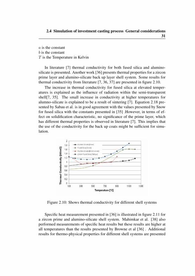

32 Chapter 2. Frame of reference
in literature [38]. The results from Mahimkar et al. [38] also illustrate thatthere is a big difference in using a real shell and the raw material making upthe shell.
Figure 2.11: Illustrates specific heat for a alumino-silicate shell system
As stated earlier the time the shell is exposed to air before melt pouringis in the range of 20-30s. During this time heat is lost to the ambient and thegoverning mechanism for heat transfer is radiation. Therefore emissivity needsto be considered in order to have actual mould temperature at the time of mouldfilling. In figure 2.12 properties for emissivity are reported from literature fordifferent shell systems [35, 36, 39].
The permeability of the shell is an important factor for thin walled castingsbecause it controls the ability to release gases from the cavity during filling. Acommon way to increase permeability is to use venting of mould to guaranteeevacuation of gases during filling and thereby preventing premature freezingdue to back pressure. As the prime layer is limiting the overall permeability,the use of only one layer will increase permeability. The drawback of usingonly one prime layer is however that the surface defects may occur [40]. Wolfeet al. [40] showed that the shell permeability could be improved by makingchanges in the intermediate layers. Kline et al. [41] carried out a work in whichthey added fine carbon particles to the investment slurry. During burn out theseparticles created small voids in the investment shell and thereby increased thepermeability. Values for permeability are presented by Snow [7] for differentshell systems, see table 2.1 and 2.2.
Following permeability data for a zircon prime layer and alumino-silicate
2.4 Simulation of investment casting process General considerations33
Figure 2.12: Shows emissivity for different shell system presented in literature
System Porosity[%]
Permeability [10-13 m2]
Fused silica slurry with fused silica 30/50 stucco, [7] 24.6 1.83Alumino-silicate slurry with alumino-silicate 16/30 stucco, [7] 23.2 0.86Fused silica slurry with alumino-silicate 16/30 stucco, [7] 24 1.82
Table 2.1: Permeability for different shell systems, [7]
back up coats shell system [36]
Temperature [C] 21 1200 1200 after 1 hourPermeability [m2] 0.74x10-
130.72x10⁻¹³ 0.93x10⁻¹³
Table 2.2: Permeability for a zircon prime layer and an alumino-silicate backup shell, [36]
Mechanical data are of the shell system are vital for simulation of deforma-tions and stresses during casting. The stiffness of the shell needs to be incorpo-rated due to the fact that it will constrain the shrinkage of the casting to someextent. Poisson’s ratio, as a part in the elastic constitutive equitation, needsalso to be defined. Thermal strains are important for simulations because itwill affect the behaviour of heat transfer. The behaviour during heating is alsoimportant for the dimensions of the wax pattern.
Following table summarizes Youngs Modulus for different shell systems

34 Chapter 2. Frame of reference
Figure 2.13: Shows linear thermal strain[7]
from [7] and [42], whereas thermal expansion for different shell systems ispresented in figure 2.13. Additional results for thermal strain measurement canbe found in [43]. For Poissons ratio, no reliable information has been found inliterature and thus needs to be approximated for simulation work.
It can be seen from literature that the material properties needed for simu-lation is not clear. Therefore measurement of thermo-physical properties needsto be performed on that particular shell system which is going to be used forcasting
Shell system Stiffness[GPA]
Fused silica slurry fused silica 30/50 stucco [7] 5.0Alumino-silicate slurry alumino-sliicate 16/30 stucco, [7] 5.3Fused silica slurry alumino-silicate stucco, [7] 4.2Zircon Fused silica system ,[42] 2.6
Table 2.3: Stiffness of the ceramic mould, from [42][7]
Chapter 3
Methodology
To develop new knowledge about the effect of different process parameterson cast-ability of thin-walled complex components, experimental studies wereconducted using existing knowledge available about casting and solidificationin genral. The reason to choose experimental studies for producing data wasto evaluate actual casting conditions from an industrial set-up. Experimentalnature of the work was also important in order to produce industrial demon-strations. The important parameters that influence the fillablity and flowabilityin genral were identified from the literature, [1, 4, 6, 13, 18, 22, 24]. In orderto evaluate the effect of identified parameters on the castability of thin-walledcastings, a experimental study was designed. In the experimental study 1, ef-fects of casting parameters , i.e. casting temperature, shell pre-heat temperatureand pressure head were evaluated in terms of fill-ability and flow-ability in thinwalled-casting. In this work alloy related parameters, i.e thermodynamics ofalloys and composition are not evaluated as in general foundry practices thealloys follow standards and changes in composition is not usually acceptablefor sophisticated applications like gas turbines for aircraft engines.
Literature [12, 15, 16, 19, 44, 45] suggest that filling mode also have effecton mould filling. In order to evaluate the effects of filling mode on castabilityof thin-walled section flow of metal into thin-sections was also evaluated whichis observed to be effected by filling pattern. Top-gated and bottom-gated modeof filling, which has been reported [45] crucial for the mould filling, were eval-uated in terms of their effect on laminarity of flow in thin-strip like geometry,In order to apply the results from experimental study 1 to produce complexindustrial components, a second study was designed. Since thin components
35

36 Chapter 3. Methodology
in industrial applications demand very high quality standards, the soundness ofcasting is very important. Additional parameters related to defects formationwere included in experimental study 2. From the literature [25, 27, 28, 29, 46]it was concluded that the solidification morphology is important to producequality castings. In order to control the solidification morphology, the effect ofthermal gradient and heat transfer rate is evaluated in terms of grain size andshrinkage porosity. The experimental study 2 is significantly important in or-der to apply results from the experimental study 1 to produce a complex turbinecomponent. The experimental study 2 also adds knowledge on effect of otherfoundry conditions on the quality of castings. In order to achieve different heattransfer rate, 8 different types of insulation pattern were designed. The designof insulation pattern was conceived from the shape of the test geometry andprinciples of heat transfer with respect to test geometry. The design of insu-lations needed lots of consideration as it was a dependent parameter and hadinfluence from other parameters i.e. casting temperature, local thermal gradi-ent induced by shell thickness and solidification pattern inside the geometry.To produce condition for different thermal gradient at mould/metal interface,ceramic shell were produced with two different thickness. To establish therelation between dependent variables, the results were analyzed statistically.
The studies presented in this work are experimental in nature, which in-volves literature review, developing a mathematical and theoretical model ofrelevant parameters, applying the model on test geometries in order to findthe most influential parameters. The studies provide a new mathematical andtheoretical model for complex thin-walled components and presents most in-fluential foundry parameters that can be applied and simulated on geometriesthat have complex features and require high level of accuracy and quality.
The results from the work has been applied in a commercial simulationsoftware Nova Flow & Solid CVTM[47]. The software capabilities are en-hanced which now provide very good agreement with actual casting conditionsand their effects.
3.1 Experimental Study 1
3.1.1 Experimental procedure for cast-ability study
To study the effects of casting parameters on cast-ability and quality of cast-ings, geometries with two different thickness, i.e. 1.5 mm and 2 mm wereassembled on both conventional top-gated and bottom-gated runner system.
3.1 Experimental Study 1 37
The test geometry used was a curved blade of 100 x 150 mm with a base of120 x 20 x 20 mm. In order to establish a relationship between casting pa-rameters and fluidity, a set of experiments was designed. The alloy used inthis study was a aero-space grade of steel, 17-4PH. The reason to choose the17-4PH was it’s potential application in aero-space industry as a suitable alloyfor many structural applications. The parameters studied were superheat, shellpreheat temperature, thickness of test geometry and mode of filling. The se-lection of parameters were based on their significance on fillability and flowa-bility as found in literature. To produce data for simulation work, the thermalproperties of the ceramic shell and thermodynamic data for 17-4PH were alsocollected. Shell properties were measured in lab-scale experiments. For thealloy properties, however, commercial software JMatPro [48] was used.
Geometry and gating system
(a) Casting geom-etry
(b) Gating principle, top and bottom-gated runner system
Figure 3.1: Illustrating sample test geometry and filling modes
The method used in the casting trials was a top-down pouring (top-gatedfilling), and bottom-up pouring (bottom-gated filling). The principle for theset-up is shown schematically in figure 3.1. The sprue used in tree design was300 mm high with a diameter of 40 mm. The pouring cup attached to spruewas 125 mm high and 125/60 mm in diameter. The runners were 40x40 mmin cross-section. The gating was designed such that the entire cross-section ofthe base of blade was attached to the runners. No additional feeders were used.Test geometries were mounted on runner systems (trees) both in top-gated andbottom-gated configurations.
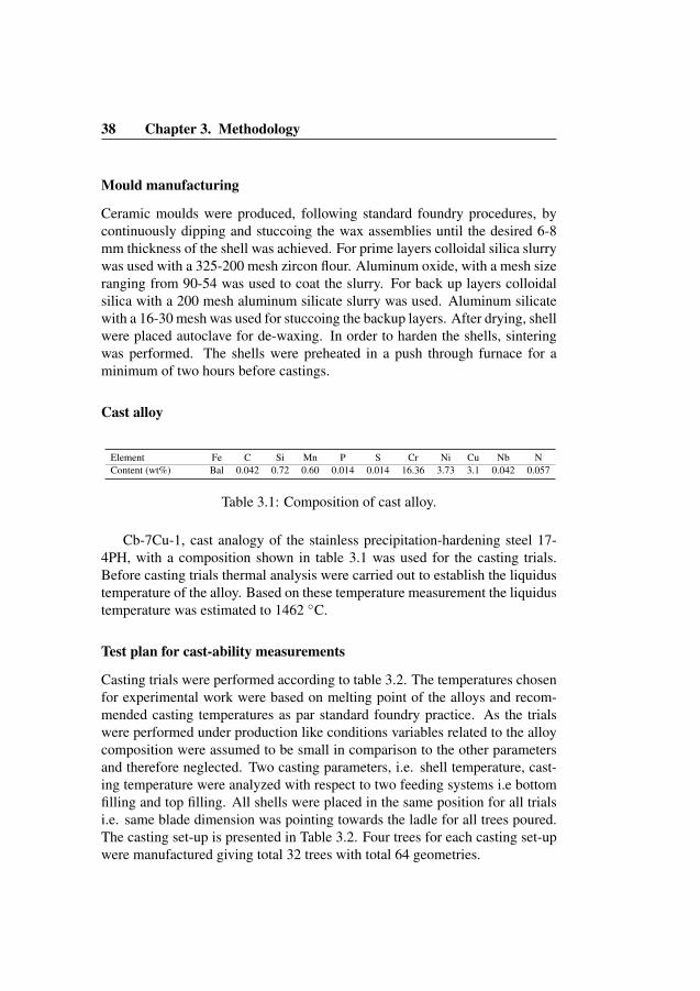
38 Chapter 3. Methodology
Mould manufacturing
Ceramic moulds were produced, following standard foundry procedures, bycontinuously dipping and stuccoing the wax assemblies until the desired 6-8mm thickness of the shell was achieved. For prime layers colloidal silica slurrywas used with a 325-200 mesh zircon flour. Aluminum oxide, with a mesh sizeranging from 90-54 was used to coat the slurry. For back up layers colloidalsilica with a 200 mesh aluminum silicate slurry was used. Aluminum silicatewith a 16-30 mesh was used for stuccoing the backup layers. After drying, shellwere placed autoclave for de-waxing. In order to harden the shells, sinteringwas performed. The shells were preheated in a push through furnace for aminimum of two hours before castings.
Cast alloy
Element Fe C Si Mn P S Cr Ni Cu Nb NContent (wt%) Bal 0.042 0.72 0.60 0.014 0.014 16.36 3.73 3.1 0.042 0.057
Table 3.1: Composition of cast alloy.
Cb-7Cu-1, cast analogy of the stainless precipitation-hardening steel 17-4PH, with a composition shown in table 3.1 was used for the casting trials.Before casting trials thermal analysis were carried out to establish the liquidustemperature of the alloy. Based on these temperature measurement the liquidustemperature was estimated to 1462 ◦C.
Test plan for cast-ability measurements
Casting trials were performed according to table 3.2. The temperatures chosenfor experimental work were based on melting point of the alloys and recom-mended casting temperatures as par standard foundry practice. As the trialswere performed under production like conditions variables related to the alloycomposition were assumed to be small in comparison to the other parametersand therefore neglected. Two casting parameters, i.e. shell temperature, cast-ing temperature were analyzed with respect to two feeding systems i.e bottomfilling and top filling. All shells were placed in the same position for all trialsi.e. same blade dimension was pointing towards the ladle for all trees poured.The casting set-up is presented in Table 3.2. Four trees for each casting set-upwere manufactured giving total 32 trees with total 64 geometries.
3.2 Experimental Study 2 39
Mould temp. (◦C) Pouring temp.(◦C) Filling direction
No.:1 900 1550 top-gatedNo.:2 900 1550 bottom-gatedNo.:3 1100 1550 top-gatedNo.:4 1100 1550 bottom-gatedNo.:5 900 1700 top-gatedNo.:6 900 1700 bottom-gatedNo.:7 1100 1700 top-gatedNo.:8 1100 1700 bottom-gated
Table 3.2: Test plan for test geometries.
3.2 Experimental Study 2
3.2.1 Experimental procedure to evaluate effect of processparameters on casting defects
In this experimental work a typical turbine blade geometry for an industrialgas turbine was selected, with chord length of 89 mm, leading edge thickness0.56 mm and trailing edge thickness 1.05 mm. The motivation to choose thisgeometry was its complexity, thin cross section and required very high qualitystandards. The cluster was designed to optimize fluid flow in the cavity basedon results of a number of simulations. Simulations were performed using thecommercial software package Nova Flow & Solid CVTM[47]. Well establishedprinciples for gating design from previous work [8, 44] were considered to de-sign a cluster.
Alloy composition
Ceramic shell
The ceramic shell material used for the experimental work was water based col-loidal silica. The inner most layer consisted of CoAl2o4 as a grain refiner andcolloidal silica bound ZrSiO4 with Alumina oxide as stucco. Priming layersconsisted of colloidal silica with a 325-200 mesh zircon flour. Alumina witha mesh size of 90-54 was used as stucco. For back up layers colloidal silicawith a 200 mesh aluminum silicate slurry was used. 16-30 mesh aluminum sil-icate was used as stucco in backup layers. The shell properties were measuredempirically. The specific heat capacity Cp of ceramic mould was measured

40 Chapter 3. Methodology
Element Content wt %
Nickel, Ni 53Chromium, Cr 17.5
Cobalt, Co 16.5Molybdenum, Mo 4
Iron, Fe 4Titanium, Ti 3.9
Aluminum, Al 2.9Boron, B 0.01
Table 3.3: Typical composition for Udimet 500TM
with a differential scanning calorimeter Netzsch STA 404CTMequipment at atemperature range between 25◦C to 1200◦C as shown in Figure 3.2.
0 200 400 600 800 1000 12000,70
0,75
0,80
0,85
0,90
0,95
1,00
1,05
1,10
Spe
cific
Hea
t (cp
, J/g
K)
Temperature (°C)
Specific Heat
Figure 3.2: Specific heat of shell measured at different temperatures
In order to measure thermal diffusivity α of the mold, measurements weretaken at temperature intervals 900-1300◦C using a Laser-Flash Netzsch LFA427/4/GTM. The values of thermal diffusivity with respect to temperature areshown in Figure 3.3.
3.2 Experimental Study 2 41
0 200 400 600 800 1000 12000,46
0,48
0,50
0,52
0,54
0,56
0,58
0,60
0,62
0,64
Ther
mal
diff
usiv
ity (m
m2/
s)
Temperature (°C)
Thermal diffusivity
Figure 3.3: Thermal diffusivity of shell measured at different temperatures
Density was measured in a temperature range between 25◦C and 1200◦Cusing a Netzsch DIL 402C/4/GTMdilatometer and the values of density vs. tem-perature are shown in Figure 3.4.
Thermal conductivity was calculated from thermal diffusivity, specific heatand density measurements [46].
λ(T ) = α(T )ρcp(T ) (3.1)
Test geometry and gating design
The cluster design selected for experimental work is shown in Figure 3.6. Cast-ing trials were performed to verify the effect of improved fluid dynamic con-ditions in the mould cavity. It was noted that by maintaining a laminar flowinside the mould cavity and by avoiding metal splashes as well as directing themetal stream towards the thin section, miss-runs can be significantly avoided.Filling the thin section first helps to keep the flow channel open thus ensuringcomplete filling.
The gating and cluster design is critical in casting of thin-walled compo-nents since filling must be completed before solidification significantly reduces

40 Chapter 3. Methodology
Element Content wt %
Nickel, Ni 53Chromium, Cr 17.5
Cobalt, Co 16.5Molybdenum, Mo 4
Iron, Fe 4Titanium, Ti 3.9
Aluminum, Al 2.9Boron, B 0.01
Table 3.3: Typical composition for Udimet 500TM
with a differential scanning calorimeter Netzsch STA 404CTMequipment at atemperature range between 25◦C to 1200◦C as shown in Figure 3.2.
0 200 400 600 800 1000 12000,70
0,75
0,80
0,85
0,90
0,95
1,00
1,05
1,10
Spe
cific
Hea
t (cp
, J/g
K)
Temperature (°C)
Specific Heat
Figure 3.2: Specific heat of shell measured at different temperatures
In order to measure thermal diffusivity α of the mold, measurements weretaken at temperature intervals 900-1300◦C using a Laser-Flash Netzsch LFA427/4/GTM. The values of thermal diffusivity with respect to temperature areshown in Figure 3.3.
3.2 Experimental Study 2 41
0 200 400 600 800 1000 12000,46
0,48
0,50
0,52
0,54
0,56
0,58
0,60
0,62
0,64Th
erm
al d
iffus
ivity
(mm
2/s)
Temperature (°C)
Thermal diffusivity
Figure 3.3: Thermal diffusivity of shell measured at different temperatures
Density was measured in a temperature range between 25◦C and 1200◦Cusing a Netzsch DIL 402C/4/GTMdilatometer and the values of density vs. tem-perature are shown in Figure 3.4.
Thermal conductivity was calculated from thermal diffusivity, specific heatand density measurements [46].
λ(T ) = α(T )ρcp(T ) (3.1)
Test geometry and gating design
The cluster design selected for experimental work is shown in Figure 3.6. Cast-ing trials were performed to verify the effect of improved fluid dynamic con-ditions in the mould cavity. It was noted that by maintaining a laminar flowinside the mould cavity and by avoiding metal splashes as well as directing themetal stream towards the thin section, miss-runs can be significantly avoided.Filling the thin section first helps to keep the flow channel open thus ensuringcomplete filling.
The gating and cluster design is critical in casting of thin-walled compo-nents since filling must be completed before solidification significantly reduces

42 Chapter 3. Methodology
0 200 400 600 800 1000 1200 1400
2,450
2,455
2,460
2,465
2,470
2,475
2,480
2,485
2,490
2,495
Den
sity
(g/c
m3)
Temperature (°C)
Density
Figure 3.4: Density of shell measured at different temperatures
0 200 400 600 800 1000 1200
1,10
1,15
1,20
1,25
1,30
1,35
1,40
1,45
Ther
mal
Con
duct
ivity
(W/(m
*K))
Temperature (°C)
Thermal Conductivity
Figure 3.5: Thermal conductivity of shell measured at different temperatures
3.2 Experimental Study 2 43
the melt flow [49]. Previous work [44, 49] has shown that bottom-filling helpsto reduce turbulence in the mould. The combined effect of top-filling and bot-tom filling is applied to design a cluster for this experimental work to achieverapid filling with laminar flow. A central runner was extended beyond the bot-tom feeder arms to allow metal to fill the stem and gradually rise up to feedthe runners. Sharp bends and abrupt changes in direction were avoided in thefeeder to decrease turbulence and air aspiration. Blades were assembled on theupper edge of the runner to ensure that metal was fed to the blades simulta-neously thus maintaining a laminar flow. Blades were mounted on runners ina ”top-fill” configuration with 4 blades on each arm. 16 blades were assem-bled on a 4 arm cluster. The total weight of the assembly including cast bladesand runner system was 11 kg. Using the Novacast simulation software castingspeed was determined to be 1.4 kg per second. It was noted that If the castingspeed is too high turbulence will effect feed into the cavity whereas if it is toolow significant heat loss from the mould will affect the quality [44].
Blades are adjusted at an angle with the feeding arm to get maximum lam-inarity and to avoid causing splashing or turbulence. Clusters were cast in ahanging position in the vacuum furnace to keep the tree as vertical as possible.Feed rate and feed time was kept constant. Reynolds numbers were calculatedand a design with low Reynolds number was considered for experiments. Alow Reynolds number means less turbulent flow.
NRe =4RhV d1
µ(3.2)
It has been found experimentally[8] that flow is laminar when the Reynoldsnumbers is below 2000. A stable boundary layer will exist when the Reynoldsnumber is below 2000. Above 20000 severe turbulence causes the boundarylayer to become unstable and break up. Since density, d1 and viscosity, µare properties of the metal and cannot be changed, velocity, V, or hydraulicradius, Rh must be adjusted to reduce the Reynolds number. Reduced meltvelocity in the feeder will prolong filling time and increase chances of miss-run. The best combination of melt velocity and flow laminarity is achievedusing a rectangular feeder channel where it is well established that the Rh isminimized. [8].
An optimized cluster design was used in experimental work to investigatethe effect of casting parameters on porosity and grain size. A range of valuesfor different parameters was selected from the simulations. The experimentswere design to observe the significance of one parameter at a time keeping

44 Chapter 3. Methodology
Figure 3.6: Tree design for blade casting
the other parameters constant. The casting trials were performed according toexperimental set up presented in Table 3.4.
Insulation type Temperature 1500 ◦C Temperature 1520 ◦C Temperature 1540 ◦C Temperature 1560 ◦C
Type 1 9 and 11 mm Shell 9 and 11 mm Shell 9 and 11 mm Shell 9 and 11 mm ShellType 2 9 and 11 mm Shell 9 and 11 mm Shell 9 and 11 mm Shell 9 and 11 mm ShellType 3 9 and 11 mm Shell 9 and 11 mm Shell 9 and 11 mm Shell 9 and 11 mm ShellType 4 9 and 11 mm Shell 9 and 11 mm Shell 9 and 11 mm Shell 9 and 11 mm ShellType 5 9 and 11 mm Shell 9 and 11 mm Shell 9 and 11 mm Shell 9 and 11 mm ShellType 6 9 and 11 mm Shell 9 and 11 mm Shell 9 and 11 mm Shell 9 and 11 mm ShellType 7 9 and 11 mm Shell 9 and 11 mm Shell 9 and 11 mm Shell 9 and 11 mm ShellType 8 9 and 11 mm Shell 9 and 11 mm Shell 9 and 11 mm Shell 9 and 11 mm Shell
Table 3.4: Design of experiments
Chapter 4
Results
To answer the research questions presented in chapter 1, systematic empiri-cal investigation of data produced by measurements was conducted. Carefullycollected empirical data from study 1 and 2 was analyzed and interpreted forthe purpose of discovering patterns of relationships between process parame-ters and the castability into thin-sections. In order to develop a relationshipbetween process parameters and the castability, the experimental data was an-alyzed using different analysis tools. Digital image processing was used tomeasured the fillibility in study 1. Image processing program, ImageJ [50] wasused to measured filled area in the test geometries. Dye penetrant inspectionand light optical microscopy was used to analyze the porosity in test geome-tries. For the experimental study 2, radiography and optical microscopy wasused to measure shrinkage and grain size.
4.1 Experimental Study 1
For the experimental study 1 results were evaluated in terms of filled area in1.5 mm and 2 mm geometries. Temperature drop in shell during transporta-tion was also recorded to evaluate variation on shell temperature. By usingconventional thermal imaging camera, pouring process for each casting wasfilmed to estimate and verify the pouring time, shell temperature and melt tem-perature at the time of pouring. The internal temperature of the mould was alsomeasured using a K type thermocouple. The temperature drop measurementswere important to evaluate the impact of shell temperature on the fluidity. As
45

46 Chapter 4. Results
temperature drop in the shell is not constant over the period of time, it is im-portant to relate actual shell temperature at the time of casting to the filled areain geometry. The temperature vs. time graph in Figure 4.1 shows the rapidcooling immediately after shell removal from preheat furnace.
0 50 100 150 200 250650
700
750
800
850
900
950
1000
1050
1100
1150Temperature
Tem
pera
ture
(Deg
ree
C)
Time (Seconds)
Figure 4.1: Illustrates temperature drop inside the shell during transport.
4.1.1 Fluid behaviorIn figure 4.2, 4.3 and 4.4 typical fluidity results are shown. A distinctive differ-ence in flow pattern was noticed between the top and bottom-gated runner sys-tems. For the top-gated system a non-uniform filling occurred over the widthof the blade which resulted in a unzipping type of propagation of melt. For thebottom-gated system however, where the metal moved in the opposite directionof gravity no unzipping type of propagation was observed. These differencesbetween top and bottom-gated runner systems appeared to be valid for all cast-ing trials.
4.1.2 Effects of process parametersNormalized filled area was calculated with digital image processing and usedas a measure of filling, ranging from 0.0 to 1.0. A schematic illustration isshown in figure 4.5. The area calculation was performed in the open sourcesoftware ImageJ. A completely filled blade corresponding to a fluidity of 1.0was used as reference.
4.1 Experimental Study 1 47
(a) 1.5 mm top gatedcasting at 1700 ◦C -setup 5
(b) 1.5 mm top gatedcasting at 1550 ◦C-setup 1
Figure 4.2: Effect of casting temperature on fluidity
(a) 1.5 mm top-gatedcasting at shell tem-perature 900 ◦C- setup1
(b) 1.5 mm top-gatedcasting at shell tem-perature 1100 ◦C-setup 3
Figure 4.3: Effect of shell temperature on fluidity
In figure 4.6 fluidity results are compared between top-gated and bottom-gated runner systems along with the deviation of each trial for blade thickness’s1.5 and 2.0 mm. Even though the deviation is large for both casting systems theresults shows that the top-gated system results in a better cast-ability comparedto the bottom-gated system. It is also observed that metal temperature at boththickness’s has significant effect on cast-ability however shell temperature doesnot appeared to be significant.

48 Chapter 4. Results
(a) 2 mm top-gatedcasting - setup 7
(b) 2 mm bottom-gated casting - setup 8
Figure 4.4: Comparison of fluidity between top-gated and bottom-gated
Figure 4.5: Illustrates evaluation technique of projected area.
4.1.3 Porosity in thin sections
Porosity levels were evaluated by means of dye penetrant testing. Results fromthe penetrant testing are shown in figure 4.9. As can be seen the top-gatedcastings exhibit several large pores close to the surface, while the bottom-gatedcastings appear to be free from such pores. A slight overall tint, however, isseen for all samples, indicating micro-porosity.
In order to get a rough estimate of size of porosity and its nature, the sam-ples were cut from six equally distanced sections from bottom to top of theblade and were analysed using light optical microscope (LOM). The bulk sam-ple represented by 0 in figure 4.8 was taken from thicker base of the blade.Figure 4.8 shows the distribution of porosity for 2 mm blades from three dif-ferent set-ups giving the comparison between top-gated and bottom-gated sys-tems. Porosity investigations were performed along center of each section us-ing LOM. The average porosity of the samples was determined as area fraction
4.1 Experimental Study 1 49
0 1 2 3 4 5 6 7 80,0
0,1
0,2
0,3
0,4
0,5
0,6
0,7
0,8
0,9
1,0
Fille
d ar
ea
Test trails (1, 3, 5 & 7)
1.5 mm test geometry2 mm test geometry
(a) Top-gated runner system
1 2 3 4 5 6 7 8 90,0
0,1
0,2
0,3
0,4
0,5
0,6
0,7
0,8
0,9
1,0
Fille
d ar
ea
Test trials (2, 4, 6 & 8)
1.5 mm test geometry2 mm test geometry
(b) Bottom-gated runner system
Figure 4.6: Fluidity results for each set up, light gray bars 1.5 mm and darkgray bars 2.0 mm
Figure 4.7: SEM images showing large pores in top gated sample from set-up7
of investigated area, average of five measurements in 110x or 180x magnifi-cation. The uneven distribution of porosity in samples from set-up 7 is duethe sudden appearance of a number of large pores. The selected sample werefurther investigated using scanning electron microscope in order to understandporosity formation mechanism. Figure 4.7 shows a typical SEM image forsample from set-up 7 with large pores that appeared in cut-up section 3.
The results from the study 1 has been presented and analyzed in depth in

50 Chapter 4. Results
0 1 2 3 4 5 62
3
4
5
6
7
8
9
10
Por
osity
(‰)
Section Number
Set-up 7 Set-up 4 Set-up 8
Figure 4.8: Average porosity expressed as area fraction of pores for the inves-tigated samples
(a) Top gated castingsystem, setup 7
(b) Bottom gated cast-ing system, setup 8
Figure 4.9: Penetrant results for 2 mm thickness
Paper B in chapter 8.
4.2 Experimental Study 2
In the experimental study 2, the results were evaluated in terms of effects ofcasting parameters on solidification morphology and casting defects. The de-fects that were focused during evaluation of results were
4.2 Experimental Study 2 51
• Large coarse grains in the thick sections of the blade as shown in Figure4.10.
• Columnar grains growing from thin leading and trailing edge towardscenter of the airfoil as shown in Figure 4.10.
• Shrinkage in the tip-shroud area of the blade as shown in Figure 4.11.
The reason on to focus on the above mentioned defects was due to theircommon occurrence in thin-walled complex components. To find relation be-tween different casting parameters and their effect on above mentioned defects,results of experiments were statistically analysed using the commercially avail-able statistical software, OriginProTM[51].
Figure 4.10: Large grains found at Chord length of blade
Figure 4.11: Shrinkage found at the tip shroud of blade
4.2.1 Effect of temperature on shrinkage and grain sizeGeometries were cast at different temperatures to observe the effect of castingtemperature on porosity and grain size. The best results in terms of shrinkagewere observed at 1560◦C as shown in the X-ray film in Figure 4.15 however

52 Chapter 4. Results
a course grain structure was observed at the root of blade as shown in Figure4.10.
Figure 4.12: Sample location for micro structure evaluation
Figure 4.13: Grain structure in leading edge of blade at cast temperature1560◦C
It was possible to obtain a fine-grain microstructure at casting temperaturesof 1540◦C, 1520◦C and 1500◦C however shrinkage occurred at all these tem-peratures in uninsulated clusters with a standard shell thickness. It can be seen
4.2 Experimental Study 2 53
Figure 4.14: Grain structure in leading edge of blade at cast temperature1520◦C
Figure 4.15: Indication of porosity at different cast temperatures A) 1500◦C,B)1520 ◦C, C) 1540 ◦C, D) 1560 ◦C
in X-ray images of these blades shown in Figure 4.15 that the extent of shrink-age increases with decreasing casting temperature. Figure 4.16 shows the effectof the casting temperature on the area that has large course grains and Figure4.17 shows the effect of casting temperature on size of porosity. The area withlarge grains is measured by etching and measuring surface area of zone that iseffected by course and columnar grains. The shrinkage porosity was measuredfrom the X-ray films. At 1500◦C very fine grains were observed with visi-ble shrinkage porosity. To investigate the effect of insulation on the shrinkageporosity 1500◦C was selected as casting temperature for further trials.

54 Chapter 4. Results
1500 1520 1540 1560
0
200
400
600
800
Are
a ef
fect
ed w
ith la
rger
gra
ins
(Squ
are
mm
)
Casting temperature (°C)
9mm shell11mm shell
Figure 4.16: Effect of casting temperature on grain size
4.2.2 Effect of insulation on porosity and grain size
Various patterns and thickness of insulation were applied to control heat flowand cooling rate in the airfoil. The intent was to control the solidification rateand direction. Results are presented in Figure 4.18 and 4.19.Summarized below are the different types of insulations pattern and thicknessused in the casting trials.Type 1: No insulation.Type 2: 6 mm Complete airfoil.Type 3: 12 mm Complete airfoil.Type 4: 6 mm on bottom half at root side of airfoil and 12 mm on top half.Type 5: 6 mm on bottom half at root side of airfoil and 12 mm on top half + 6mm at tip shroud.Type 6: 12 mm on bottom half at root side of air foil and 6 mm on top half.Type 7: 6 mm on 2/3 of bottom side at root of airfoil and 12 mm on 1/3 of top.Type 8: 6mm on 1/3 of bottom side at root of airfoil , 12 mm on middle and 18mm on 1/3 of top.
To investigate the effect of insulation on the shrinkage porosity inside theairfoil, only airfoils were insulated. Variation in insulations patterns and thick-ness significantly effected the size of the porosity as shown in Figure 4.19.
4.2 Experimental Study 2 55
1500 1520 1540 15602
4
6
8
10
12
14
Siz
e of
por
ous
zone
(Squ
are
mm
)
Temperature (°C)
9mm shell11mm shell
Figure 4.17: Effect of casting temperature on Porosity at two different shellthickness
0 1 2 3 4 5 6 7 8 9
0
200
400
600
800
1000
1200
Are
a ef
fcte
d by
larg
er g
rain
s (S
quar
e m
m)
Insulation Type (Type and Location)
1500 C1520 C1540 C1560 C
Figure 4.18: Effect of insulation type on grain size at different temperatures
To determine effect of insulation on fillability and grain size, trials were alsoperformed using insulation at the feeder and in-gates. It was observed that if

56 Chapter 4. Results
0 1 2 3 4 5 6 7 8 9
0
5
10
15
20
25
Siz
e of
por
ous
zone
(Squ
are
mm
)
Insulation type (Type and location)
1500 C1520 C1540 C1560 C
Figure 4.19: Effect of insulation type on size of porosity at different tempera-tures
feeder and in-gates are insulated, larger grains can appear at the root of bladeı.e. adjacent to the feeder can appear at 1500◦C. No significant effect of insu-lated in-gates and feeders was observed in terms of fillablity.
4.2.3 Effect of shell thickness on porosity and grain size
Shell thickness was observed to have very significant effect on shrinkage. Itwas possible to eliminate shrinkage by increasing shell thickness. The effectof varying shell thickness is presented in the graph in Figure 4.16 and 4.17. Itwas observed that increased shell thickness not only minimized shrinkage andcolumnar grain formation but also eliminated surface defects. However effectof increased shell thickness on grain size was not significant.
4.2.4 Effect of time to cast on Porosity
To verify effect of time from preheat oven to completion of casting on porositydata was analyzed statistically and it was observed that time in casting signif-icantly effects porosity related defects as shown in Figure 4.20. In the graph,the size of porosity is quantified as a function of time-to-cast.
4.3 Verification of results by simulations 57
110 120 130 140 1500
2
4
6
8
10
12
14
16Size of porous zone
Siz
e of
por
ous
zone
(Squ
are
mm
)
Time to cast (Seconds)
Figure 4.20: Effect of time to cast on shrinkage porosity
The results from the study 2 has been presented and analyzed in depth inPaper A and C in chapters 7 and 9 respectively.
4.3 Verification of results by simulationsTo verify observations regarding the effect of mould thickness on Niyama valueand thus on shrinkage porosity, simulations were done with different shellthicknesses. After introducing shell properties into the simulation model, agood match between actual casting trials and simulation was observed. Withincreasing ceramic shell thickness, an increase in Niyama value was observedpredicting a lower probability for occurrence of shrinkage porosity. Figure 4.21presents the effects of shell thickness on size of porosity in a commercial soft-ware package Nova Flow & Solid CVTM[47]. By increasing shell thickness,the size of shrinkage porosity reduced and it moved away from the intersection.The new location of porosity in 4.21 (b) is easy to feed by adding insulations,and thus achieving longer feed distance. The scale in figures show the % ofshrinkage 4.21 (a) and their equivalent Niyama value 4.21 (b). It was observedthat the best results were obtained with a combination of thicker shell as well asoptimized insulation. To find a critical value below which shrinkage porosity

58 Chapter 4. Results
appears, it is important that the simulation data is calibrated for the shell andalloy system being studied. Commercially available software JMatProTMwasused to obtain thermodynamic data for Udimet 500 and shell properties weredetermined empirically by laboratory scale experiments. Similarly, to see theeffect of insulation on cooling rate in different sections of the blades, types ofinsulation were introduced in simulation software. It was observed that variousinsulation types have different effects on thermal modulus in different sectionsof blades. Scale of thermal modulus in the simulation software were also ad-justed to get accurate predictions of grain size in different sections of blades.
Further work is being carried out to develop adjustment process for simula-tion model for investmnet casting of thin-walled complex components. InverseModeling Technique [52] is being used to perform adjustments in models pa-rameters in order to achieve a match between measured and modeled behavior.The simulation work has not been used for publication purposes, however fu-ture work will lead to at least one publication on simulation and modeling ofcasting process for thin-walled sections.
4.3 Verification of results by simulations 59
(a) Large shrinkage pore at 9 mm shell thickness
(b) Shrinkage pore at 11 mm shell thickness
Figure 4.21: Simulation predicting the effect of two shell thickness on shri-nakge porosity
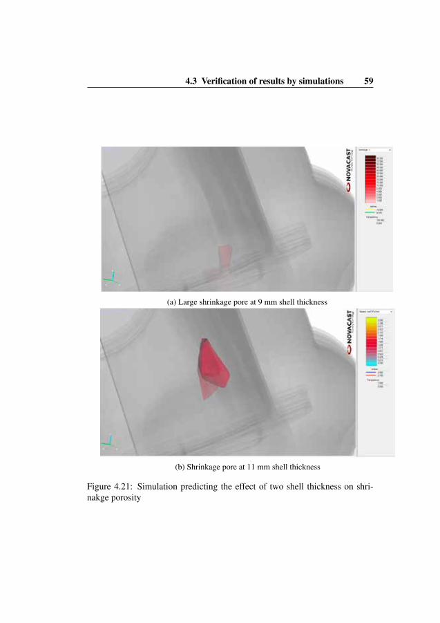
60 Chapter 4. Results
4.4 Limitation of the experimental studiesDue to the fact that all experimental work was performed in the industrial set-up , there are some limitation associated with the work. Not all process pa-rameters could be tested in a production set-up. For example, to create extrapressure head partial vacuum at the bottom of mould cavity is promising meth-ods presented in literature, however, due to limitation in vacuum furnace atfoundry, it was not possible to test partial vaccum. Major modification in shellsystem was not possible due to the programming limitations in robots whichruns the production batches. There were also limitation associated with shellpreheat temperature due to the limited possibilities of temperature variation inpre-heat oven. In general, design of experiments was also effected and influ-enced by the industrial limitations and thus not all of process parameters aretested.
Chapter 5
Discussion
RQ 1: How do the casting parameters influence fillability and flowabilityin thin-walled castings.
It was observed that casting temperature has significant impact on fluidity, asobserved from both studies about castability and defect formation as shownin figures 4.2, 4.6 and 4.15, which is in agreement with the previous studies[1, 9]. However mould temperature showed only a minor effect on fluidity forboth studies, as shown in figure 4.3, despite the previous work [12] showingincrease in fluidity with increase mould temperature. The insignificance ofmould temperature can be attributed to the fact that geometry used in this workare very thin and fillability governs the mould filling process. The argumentcan be supported by another work [15] where similar thickness were tested.The other reason could also be the delay in pouring during transportation andpouring preparation resulting in significant drop in the shell temperature at thetime of pouring. This argument is supported by the test showing the temper-ature drop during transportation, presented in the figure 4.1. It is importantto consider that the 1100◦C shells cooled more rapidly due to stronger radi-ation losses as compared to the 900◦C shells, making temperature differencebetween both tested mould temperatures insignificant. In the top-gated sys-tem, as observed in castability study, the effect of surface tension was morepronounced, see figure 4.2. As the metal flow during top-gated filling is turbu-lent, a solid film forms rapidly on the surface of flowing metal stream. Due tofriction, the solidified film was pinned to the walls of the cavity while a newsolid layer continued to form at the surface of flowing stream. The pinning
61

62 Chapter 5. Discussion
effect caused splits at the surface of flowing stream allowing the metal streamto flow only along the strong chains of solid films. The liquid stream keptflowing as long as velocity of the liquid and pressure head was sufficient tobreak the surface film [6]. This phenomenon which was clearly observed inthe top-gated system, is described as unzipping type of propagation in the re-sults section. In the bottom-gated system, however, the melt propagation wassmoother. It was also observed both in top-gated and bottom-gated systemsthat due to the thermal expansion of the ceramic shell, the vertical edges of thegeometry were cracked and opened-up resulting in an increase in thickness atthe edges as compared to the center of mould cavity. The capillary repulsionin the thinner channel stops metal flow and diverts it to the thicker areas wherecapillary repulsion is lower[6]. The phenomenon is shown in in figures 4.4where more filling on the edges of geometry is observed. Turbulent flow in thetop-gated system, also causes porosity and shrinkage. A high level of porositywas observed in the top-gated system as compared to the bottom-gated system,as presented in figures 4.7 and 4.8. Figure 4.8 shows that castings from set-up7, which is top-gated system have more porosity than the castings from set-up4 and 8 which are bottom filled. These results are supported by the previouswork [45, 53] in which it is shown that the level of porosity and inclusions arehigher for top-gated systems compared to bottom-gated systems. Differencesin porosity between the casting systems appeared to be dependent on the modeof filling. For the bottom-gated casting system the velocity of the melt into thethin cavity is controlled by the inlet system. Also the molten metal move up-ward forming a planar smooth surface and thereby not exposed to air except atthe flow tip. For the top-gated system, however, the filling is uncontrolled andthe metal enters the cavity in a non-uniform way, i.e. metal is exposed to airwhich could result in bi-oxide films, later acting as nucleation sites for pores.Furthermore, uncontrolled filling could potentially entrap a great amount ofair, which may not be evacuated during solidification. At higher temperatureair has a higher solubility in the melt, thus entrapment of oxides is aggravatedin case of turbulent filling. The results from the experimental study are sub-mitted to the journal, see Paper B in chapeter 8, and answers to the ResearchQuestion 1, as described in Chapter 1.
RQ 2: How do the casting parameters influence the quality of thin-walledcomplex castings in terms of microporosity and grain structure.
The effect of casting parameters on casting defects was evaluated in experimen-tal study 2. It was observed that casting temperature, insulation and shell thick-
63
ness are key process parameters for eliminating shrinkage, missruns and nonuniform grain structure in air-foil castings as shown in graphs 4.16, 4.17 ,4.18,4.19. Eliminating shrinkage and missruns while maintaining a fine grained mi-cro structure requires a trade-off [54]. Melt temperature must be high enough toensure flowability of metal inside the mould [1, 9]. At higher temperature i.e.1560◦C shrinkage porosity was completely avoidable due the the prolongedfeeding of melt as shown in figure 4.15. Availability of excess thermal en-ergy however drives grain coarsening [2]. High casting temperature resulted incoarse grains at the root of the blade due to higher thickness at root and highheat mass from the adjacent feeding arm. Figure 4.14 shows the large grains atthe root of the blade cast at 1560◦C. The effect of casting temperature on grainsize in a section shown in in figure 4.12 is presented in graph 4.17. Fillabilityof thin sections does not depend on casting temperature [22]. In order to im-prove fillability it is necessary to restrict dendrite length [28]. To find optimalconditions in which good fill is achieved while minimizing grain coarsening, itis necessary to consider mechanistically what drives filling and shrinkage re-lated defects. Fillability limited by an extended mushy zone and dendrite tipnucleation in alloys with a larger solidification range, such as Udimet 500 notonly hinders the metal flow in thin sections but also causes shrinkage porosity[27]. Dendrite growth driven by thermal gradient and cooling rate effect themorphology of solidification front and width of the mushy zone [9]. Increasingshell thickness thus increasing the capacity of the mould to absorb heat leadsto a steeper thermal gradient at the metal/mould interface. At lower castingtemperature , e.g. 1520◦C shrinkage porosity was avoidable by increasing theshell thickness without increasing the size of grains at the root of the bladeas shown in 4.16, 4.17, where effect of casting temperature on grain size andporosity at two shell thickness is presented. A steeper thermal gradient hindersgrowth of dendrite arms and improves fillability in the thin sections and feedof metal to the shrinkage pores [28]. Decreasing the cooling rate also servesto limit dendrite arm length and thus the width of mush which improves metalflow through mush [2]. The best results were obtained by minimizing casttemperature to limit grain size while increasing shell thickness as well as insu-lation to control the width of mush. Figure 4.18, 4.19 describes the effect ofdifferent insulation patterns on grain size and shrinkage porosity. Other castingparameters that indirectly effect the casting quality were also observed. Delayin transfer of pre-heated shells from preheat oven to casting chamber causes adrop in shell temperature that can significantly reduce the ability of metal toflow through the mush. Similarly the vacuum level was also significant but thismay be due to temperature drop in the shell during prolonged pumping time to

64 Chapter 5. Discussion
achieve high vacuum level. The pouring rate was also significant due to the factthat higher pouring rate can cause turbulence and splashing of metal in mouldcavity. In this experimental work it was observed that by understanding materi-als behavior and casting parameters, casting defects can be avoided in complexcomponents and product yield can be improved significantly. The effects ofcasting parameters on the casting defects are presented in a conference. Thepublished paper is attached in paper part of the thesis, see Paper A in chapter7. The more detailed work covering all the studied parameters and their effecton the casting defect is submitted to the journal, see Paper C in chapter 9 andanswers the Research Question 2, as described in Chapter 1.
5.1 Shortcomings and suggestions for future re-search
Although, less flexible production process due to the uncertainties associatedwith process, limited the possibilities to improve casting conditions, howeverthe casting parameters in a production environment and their effect has beenevaluated successfully. Attempts to influence the casting conditions were notvery successful due to the difficulties in testing prototypes according to thefoundry conditions. Several failed attempts were made to apply partial vacuumin order to achieve extra pressure head, however sealing of rough ceramic shellwas problem during experiments. Similarly, application of vibration to breaksurface film and thus increase melt flow in cavity was also unsuccessful dueto the problem in achieving correct frequency and amplitude in industrial scalevibration equipment. Further attempts to improve prototypes for both, partialvacuum and vibration mechanism will be made in future research.
Chapter 6
Conclusions
From the both experimental studies it is concluded that in order to producethin-walled components in investment casting process, optimization of castingprocess is very important. The casting parameters which help fillability mightcause shrinkage related defects. Similarly the slow cooling which helps toavoid shrinkage porosity might lead to coarse grain formation. Gating systemwhich offer better fillability also causes more shrinkage porosity. In spite ofwhat is often reported about the effect of process parameters on fluidity andshrinkage in general, the optimization of casting parameters to produce a com-plex thin casting in an industrial setup has not been thoroughly investigated. Insummary; the effect of process parameters on fillability and quality of castingcan be concluded as below.
• Primary variable that effects the fillability is pouring temperature be-cause higher pouring temperature provides extra heat mass that delaysthe solidification process and allow the melt to flow longer and fill thefine details as presented in Section3.1. However, the increase in castingtemperature appeared to cause other casting defects, e.g. unwanted largegrain structure and surface defects as shown in Section 3.2 . In order toavoid unwanted large grain formation, solidification process needs to becontrolled. A well designed application of insulation can help to achievedesired solidification pattern which is essential for fillability as well asfor fine grain structure.
• A filling mode in casting has effect on the quality of castings. The bot-tom gated pouring system appeared to be stable and less affected by the
65
66 Chapter 6. Conclusions
process parameter. Less shrinkage porosity is observed in bottom gatedpouring system (see Section3.1) due to the laminar flow, however bottomgated pouring system causes decrease in melt flowability due to countergravity flow of melt. A pouring system that combines the features ofboth filling systems appeared to be useful to create laminar and longerflow of melt as presented in Section3.2.
• Shell preheat temperature did not appear significant in terms of flowa-bility and fillability (as presented in Section 3.1), however, drop in shelltemperature resulted in more shrinkage porosity as shown in Section 3.2.
• Shell thickness appeared to be very important to avoid interdendriticshrinkage porosity. Increase shell thickness created a steeper thermalgradient at melt mould interface which is, along with the slow coolingrate, important to keep the mushy zone narrow. Combination of slowcooling rate and steep thermal gradient were important to feed the meltthrough the mush and thus avoid shrinkage porosity as presented in Sec-tion 3.2.
• In order to run simulations for the casting process, it is very importantto acquire the correct material data for alloy, shell system and insulation.By introducing correct material properties in the simulation software, agood match between actual castings and simulation was possible.
6.1 Research contributionThe results from the both experimental studies bridges the gap between scienceof metal solidification and its industrial interpretation. The experimental study1 relates the mechanism of flowability and fillability to the casting conditionsthat influence the castability of thin section. Although the effect of the gatingsystem on fluidity and defect formation has been previously reported in litera-ture [45, 53], the work presented here applies these principles in an industrialenvironment using a test geometry that resembles an actual industrial compo-nent. By performing this study using a thin-walled component and optimizingthe process window to eliminate casting defects, the work contribute towardsapplication of casting science for manufacturing of thin-walled industrial com-ponents.
Similarly in experimental study 2, the relation between process parametersand mechanism of shrinkage formation is formulated. There are well estab-
6.2 Industrial implications 67
lished theories about shrinkage formation during solidification [27, 28], how-ever, it is not previously reported how the process parameters in a foundryinfluence the mechanism of shrinkage formation. The important observationfrom the experimental study 2 was the effect of shell thickness on porosity for-mation. It was observed that shell thickness along with the insulation createthe conditions that are required to fulfill the requirements of Nayama criteria[28]. The shell thickness and insulation create a steeper thermal gradient andslower cooling rate which is essential for keeping the dendrite arm length shortand thus improve flow in the mushy zone during solidification process.
Another significant contribution from the work is acquiring thermodynamicproperties of an industrial ceramic shell. This will contribute towards develop-ing a reliable simulation model for future development work.
6.2 Industrial implicationsThe results from the work presented here will enable casting of thin-sectioncomponents in alloys with wide solidification interval, which are commonlyused in gas turbine applications. The results are especially important for hotgas path components in gas turbines as the light and thin castings for suchapplications will significantly reduce the weight of turbines and thus decreasingthe fuel consumption and improving the environmental impact.
6.3 Future researchThe future work will be focused to explore alternative route of manufacturingfor thin-walled components along with testing protypes mentioned in section5.1. The initial plan is to investigate additive manufacturing and high pressuredie casting as alternative manufacturing techniques.
6.3.1 Additive Manufacturing (AM) processesThere are different well established AM process available for different materialsystems and applications. Selection of AM process for a particular materialsystem depends upon product application, raw material properties and strengthof product. AM process can be divided into different groups based on theirlayer deposition mechanism [55].
For metallic system most commonly used method is powder bed fusionprocess. Two major powder bed fusion processes are SLS (selective laser sin-

68 Chapter 6. Conclusions
tering) and SLM (selective laser melting). In this work we will focus only onselective laser melting due control on microstructure offered by the laser melt-ing process. Microstruce is very important property of the components used inhigh temperature applications. The SLM process uses true melting techniquewhich takes place at higher laser energy levels that totally melt and fuse thepowder grains. However its more difficult to avoid distortions due to shrinkageand thermal stresses.
It is plan to use SLM process to produce a Turbine component, conven-tionally being produced with Investment casting process at TPC ComponentsAB. Discussion to develop research collaboration with Malardalen Universityand Siemens Finspang is in progress. Arcam 5 or EOS M280 machine will beused to produce component. To compare the mechanical properties with con-ventionally produce part, mechanical and micro structural evaluation will beperformed. Process parameters will be investigated and optimized to achievethe goal. A process window for Inconel 718TMwill be established for manufac-turing of Heat shield used in gas turbines.
6.3.2 Pressure die casting for Ni-base turbine componentsPurpose of the work is to find application of the vacuum die casting process, de-veloped by Pratt & Whitney [56] to produce components of high strength, highvolume using nickel base and cobalt base alloy with fine grain, cast equiaxedmicrostructure. Traditional die casting has been used widely in various indus-tries. The process utilizes a metallic die in which the molten metal is injectedand held until it solidifies. The rapid cooling of the melt due to high thermalconductivity of metallic die results in very fine grain and net shape compo-nents. Traditionally the process is used to produce components in low meltingpoint alloys, e.g. zing, aluminum and magnesium, however, the Vacuum diecasting process developed by the Pratt & whitney utilizes the principle to pro-duce components in the alloys that have high melting temperature, e.g. nickelbase super alloys. The efforts have been initiated to apply the die casting pro-cess to the production of components for use in the aerospace industry usingtitanium, nickel and cobalt based alloys [56].
For the PhD work, a detailed research plan will be initiated with collabora-tion of technology owner and the potential customers. The research plan is inprocess of discussion and market study.
Bibliography
[1] J.A. Capadona and D.L. Albright. Review of fluidity testing as applied tolost-polystyrene investment castings. AFS Transactions, -:43–54, 1978.
[2] Hasse Fredriksson and Ulla Akerlind. Solidification and crystallizationprocessing in metals and alloys. Wiley, 1st edition edition, 2012.
[3] Hasse Fredriksson and Ulla Akerlind. Materials processing during cast-ing. Wiley, 1st edition edition, 2006.
[4] J. Campbell and I.D Oliff. Static and dynamic criteria for filling of thinsection molds. AFS Cast Metals Research Journal, 7:55–61, 1971.
[5] M.I. Vainer and Y.S. Lerner. Vacuum-assisted investment casting of Al-Ni-Bronze. Transactions of the American Foundrymen’s Society, 107:35–42, 1999.
[6] John Campbell. Complete Casting Handbook: Metal Casting Processes,Metallurgy, Techniques and Design. Elsevier, 1st edition edition, 2011.
[7] J.D. Snow and D.H. Scott. Comparing fused silica and alumino-sillicateinvestment referactories. Modern Casting, pages 45–47, 2001.
[8] P R. Beeley and R F. Smart. Investment Casting. The Institute of Materi-als, 2nd edition edition, 1995.
[9] M. C. Flemings. Solidification Processing. McGraw-Hill Inc, 1974.
[10] Hasse Fredriksson and Ulla Akerlind. Physics of Functional Materials.Wiley, 1st edition edition, 2008.
[11] M.C. Flemings, F.R. Mollard, and E.F. Niiyama. Fluidity of aluminium.AFS Transactions, 70:1029–1039, 1962.
69

70 Bibliography
[12] B. Walker. New type of fluidity test piece. Foundry Trade Journal,115:713–721, 1963.
[13] S. Lun, Sin, and D. Dube. Influence of process parameters on fluidity ofinvestment-cast az91d magnesium alloy. Material Science and Engineer-ing, A386:34–42, 2004.
[14] H.S. Chandraseckariah and S. Seshan. Effect of foundry variables onfluidity of investment cast nickel-base super alloys. Transactions of theAmerican Foundry Society, 110:681–695, 2002.
[15] I.D. Oliff, R.J Lumby, and V. Kondic. Some new ideas on fluidity testmold design. Foundry, 93:80–85, 1965.
[16] M.C. Magurie and F.Z. Zanner. Gating gemotry studies of thin-walled17-4PH investment castings. In 40. annual Investment Casting Institute(ICI) technical meeting, 1992.
[17] J.D. Snow. Why fused silica. In 57th Technical Conference & Expo,Investment Casting Institute, 2010.
[18] J. Campell. Thin walled castings. Material Science and Technology,4:194–204, 1998.
[19] M. Brezina and V. Kondic. Flow phenomena in investment casting. TheBritish Foundryman, 66:337–348, 1973.
[20] J. Campell. Castings. Butterworth-Heinemann, 1993.
[21] R.J. Lumby and V. Kondic. Some new ideas on fluidity design. Foundry,93:80–85, 1965.
[22] M.C. Flemings. Fluidity of metals - techniques for producing ultra-thinsections castings. 30th International Foundry Congress, -:61–81, 1963.
[23] J E. Niesse and M C. Flemings. Applications of theory in understandingfluidity of metals. Transactions of the American Foundrymen’s Society,page 685, 1959.
[24] H.S. Chandraseckariah. Effect of foundry variables on fluidity ofinvestment-cast nickel-base superalloys. ASF Transactions, 2:855–859,1994.
Bibliography 71
[25] Richard W. Heine, Carl R. Loper, and Philip C. Rosenthal. Principlesof metal casting. Tata Mc-Grawhill Publishing Co., 1st edition edition,1976.
[26] J A. Capadona and D L. Albright. Review of fluidity testing as appliedto lost-polystyrene investment casting. AFS Transactions, pages 43–54,1978.
[27] J A. Dantzig and M.Rappaz. Solidification. FPFL Press, 1st edition edi-tion, 2009.
[28] Kent D.Carlson and C.Beckermann. Prediction of shrinkage pore volumefraction using dimensionless niyama criterion. Metallurgical and Mate-rials Transactions A, 40A:163–175, 2009.
[29] D A. Porter and K E. Easterling. Phase Transformations in Metals andAlloys. V.N.R. (International) Co.Ltd, 1st edition edition, 1981.
[30] David J.Brown and Denis O’ Mahoney. Interface heat transfer in invest-ment casting of aluminum alloys. Metallurgical and Materials Transac-tions A, 32A:3055–3063, 2001.
[31] F. Binczyk, J. leziona, and A. Kocielna. Effect of modification and cool-ing rate on the macrostructure of in-713c alloy. Archives of Foundry en-gineering, 9:13–16, 2009.
[32] et al K.A. Woodbury. Determination or interfacial heat transfer coefficientin investment castings. In 49th Annual Technical Meeting, 2001.
[33] K A Woodbury, J W Woolley, and T S Piwonka. Metal/mold andmold/environment interfacial heat transfer coefficient in active and pas-sive cooling of investment castings. AFS Transactions, 2003.
[34] D.O’ Mahoney and D.J. Browne. Use of experiment and an inversemethod to study interface heat transfer during solidification in the invest-ment casting process. Experimental thermal and fluid science, 22:111–122, 2000.
[35] A.S. Sabau and S. Viswanathan. Thermophysical properties of zircon andfused silica-based shells for investment casting. AFS Transactions, pages649–661, 2004.
72 Bibliography
[36] D.J. Browne and K.Sayers. Experimental measurements of investmentshell properties and use of data in casting simulation software. Modelingof Casting, Welding and Advanced Solidification Processes, 7:441–448,1995.
[37] M.M. Rafique and J. Iqbal. Modeling and simulation of heat transferphenomena during investment casting. International journal of heat andmass transfer, pages 2132–2139, 2009.
[38] C. Mahimakar, V.L. Richards, and S.N. Lekakh. High thermo-physicalproperties of ceramic shell. In 57th Technical conference and expo, In-vestment casting institute, 2010.
[39] M. M. Franke, R. M. Hilbinger, C. H. Konrad, U. Glatzel, and R. F.Singer. Numerical determiniation of secondry dendrite arm spacing forin738lc investment castings. Metallurgical and Materials TransactionsA, 42A:1847–1853, 2011.
[40] C.M. Wolfe, K.L. Dickerson, and M.J. Hendricks. A new look at shellpermeability and the factors that impact it. In 56th Technical conferenceand expo, Investment casting institute, 2009.
[41] K.M. Kline, S.N. Lekakh, and V.L. Richards. Improving investment cast-ing mold permeability using graphite particles. AFS Transactions, pages159–165, 2010.
[42] A. Sabau and W. Porter. Alloy shrinkage factors for the investment cast-ing of 17-4ph stainless steel parts. Metallurgic and Material TransactionsB, 39B:317–330, 2008.
[43] T. Branscomb. Therman expansion of investment casting shells. In In-vestment Casting Institute, 56th technical conference & expo, 2009.
[44] D Z. Li, John Campbell, and Y Y. Li. Filling system for investmentcast ni-base turbine blades. Journal of Material Processing Technology,148:310–316, 2004.
[45] D.Z.. Li, J. Campell, and Li Y.Y. Filling systems for investment castNi-base turbine blades. Juournal of Materials Processing Technology,148:310–316, 2004.
[46] C H. Konrad, M. Brunner, K. Kyrgyzbaev, R. Volkl, and U. Glatzel. De-termination of heat transfer coeffecient and ceramic mold material pa-rameters for alloy in738lc investment castings. Journal of Materials Pro-cessing Technology, 211:181–186, 2011.
[47] Nova Flow&Solid, version 4.6r3, (2012).
[48] JMatPro SENTES.
[49] S. Lun. Sin, D. Dube, and R. trembay. An investigation on microstruc-tural and mechanical properties of solid mould investment casting ofaz91d magnesium alloy. Elsevier, Materials characterization, 59:178–187, 2008.
[50] ImageJ National Institutes of Health.
[51] Origin Pro, OriginLab, Northampton, MA.
[52] E.Anglada, A. Melendez, L.Maestro, and I. Domiguez. Adjustment ofnuumerical simulation model to the investment casting process. ProcediaEngineering , Science Direct, 63:75–83, 2013.
[53] S. Sin, D. Bube, and R. Tremblay. An investigation on microstructuraland mechanical properties of solid mould investment casting of AZ91Dmagnesium alloy. Material characterization, 59:178–187, 2008.
[54] Malur Srinivasan. Science and Technology of Casting Processes. InTech,2012.
[55] Ian Gibson, David W. Rosen, and Brent Stucker. Additive ManufacturingTechnologies. Springer, 2010.
[56] John J. Schirra, Christopher A. Borg, and Robert W. Hatala. Mechanicalproperties and microstructural characterization of vacuum die cast super-alloy materials. Superalloys, pages 553–561, 2004.

II
Included Papers
75

II
Included Papers
75

Chapter 7
Paper A:The effect of shell thicknesson defect formation ininvestment cast Ni base alloys
Mohsin Raza, Mark Irwin and Bjorn Fagerstrom
Presented at 61st Technical conference, Investment Casting Institute.
77

Chapter 7
Paper A:The effect of shell thicknesson defect formation ininvestment cast Ni base alloys
Mohsin Raza, Mark Irwin and Bjorn Fagerstrom
Presented at 61st Technical conference, Investment Casting Institute.
77
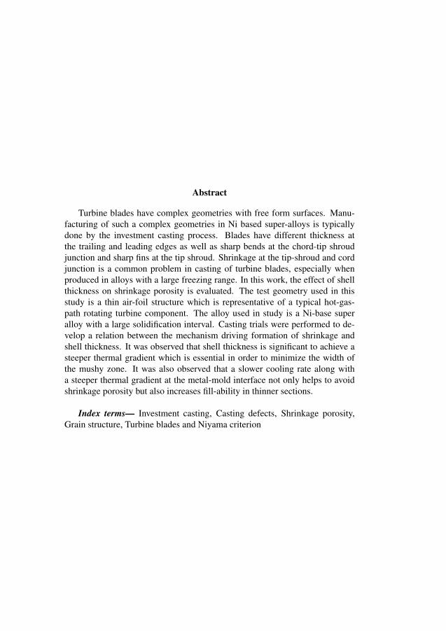
Abstract
Turbine blades have complex geometries with free form surfaces. Manu-facturing of such a complex geometries in Ni based super-alloys is typicallydone by the investment casting process. Blades have different thickness atthe trailing and leading edges as well as sharp bends at the chord-tip shroudjunction and sharp fins at the tip shroud. Shrinkage at the tip-shroud and cordjunction is a common problem in casting of turbine blades, especially whenproduced in alloys with a large freezing range. In this work, the effect of shellthickness on shrinkage porosity is evaluated. The test geometry used in thisstudy is a thin air-foil structure which is representative of a typical hot-gas-path rotating turbine component. The alloy used in study is a Ni-base superalloy with a large solidification interval. Casting trials were performed to de-velop a relation between the mechanism driving formation of shrinkage andshell thickness. It was observed that shell thickness is significant to achieve asteeper thermal gradient which is essential in order to minimize the width ofthe mushy zone. It was also observed that a slower cooling rate along witha steeper thermal gradient at the metal-mold interface not only helps to avoidshrinkage porosity but also increases fill-ability in thinner sections.
Index terms— Investment casting, Casting defects, Shrinkage porosity,Grain structure, Turbine blades and Niyama criterion
7.1 Introduction 79
7.1 IntroductionDuring the solidification of alloys, a mushy zone is formed at the solidificationfront [1]. The width of mushy zone depends upon the solidification interval,i.e. difference between melting and freezing point [2]. In nickel-base super-alloys usually the solidification interval is large which leads to formation of anextended mushy zone. The presence of mush at the solidification front restrictsthe flow of metal to the solidifying interface between liquid and solid phasescausing interdendritic shrinkage [3]. In the investment casting of complex ge-ometries, for example, turbine air foils, the solidification front grows from dif-ferent directions and meet at intersections or along the centreline. The areaswhere solidification fronts meet usually are more prone to the interdendriticshrinkage. Metallostatic pressure induced by pressure head can be calculated
Pm = ρgh (7.1)
where as bubble pressure can be calculated by
Pp − P =2σ
rp(7.2)
Since the bubble radius is usually on the order of micrometer in size andsurface tension σ is fairly large value, usually the bubble pressure Pp is morethan the metallostatic pressure [4].
Pp ≥ P +2σ
rp(7.3)
Since bubble pressure is typically much higher as compared to the metal-lostatic pressure, increased pressure head within the practical limits in invest-ment casting does not help significantly to avoid shrinkage and gas porosity.According to Niyama Criterion [3], Pores forms when
Ny =G√T ,
< const. (7.4)
where Ny is known as the Niyama constant [3], G, is thermal gradient, T ,
is the cooling rate.A large temperature gradient, G, prevents porosity because
• The mushy zone is shorter (shorter distance to feed liquid metal to thegrowing interface)

80 Paper A
• For the same cooling rate , the isotherm speed, R =T ,
G,is smaller
Therefore a smaller melt velocity resulting in a smaller pressure drop ac-cording to Darcys law [3]. Varying the mould thickness can effect the abil-ity of the mould to absorb heat and maintain a critical thermal gradient [5].The experimental setup was designed to investigate the relation between shellthickness and thermal gradient and thus shrinkage posrosity. Casting trial toevaluate the effect of shell thickness on grain size in relativly thicker section ofthe airfoil were also performed.
7.2 Experimental work
In this experimental work a typical turbine blade geometry for an industrial gasturbine was selected, with chord length of 89 mm (3.50”), leading edge thick-ness 0.56 mm (0.022”) and trailing edge thickness 1.05 mm (0.041”). Theceramic shell material used for the experimental work was water based colli-dal silica. The inner most layer consisted of CoAl2o4 as a grain refiner andcolloidal silica bound ZrSiO4 with Alumina oxide as stucco. Priming layersconsisted of colloidal silica with a 325-200 mesh zircon flour. Alumina with amesh size of 90-54 was used as stucco. For back up layers colloidal silica witha 200 mesh aluminium silicate slurry was used. 16-30 mesh aluminium sili-cate was used as stucco in backup layers. An optimized cluster design [6] with16 blades mounted on each cluster was used in experimental work to investi-gate the effect of shell thickness at different casting temperature on porosityand grain size. The experiments were designed to observe the significance ofone parameter at a time keeping the other parameters constant. The castingtrials were performed according to experimental set up presented in Table II.The experimental apparatus and some of the results presented in this articleare described in greater detail in reference [6]. The castings were evaluatedfor porosity and grain structure. For porosity evaluation, radio-graphs wereanalysed and the area of the porous zone was measured in mm2 . In order toevaluate the grain structure, castings were macro-etched to reveal the grains atsurface. The area of zone with a larger grain structure was measured. Met-allographical samples were also prepared to see the grain structure inside thecastings. The location of samples for metallography is shown in figure 1. Theresults were statistically analysed to relate the porous zone area and larger grainsurface area to the shell thickness at different casting temperatures.
7.2 Experimental work 81
Element Content wt %
Nickel, Ni 53Chromium, Cr 17.5
Cobalt, Co 16.5Molybdenum, Mo 4
Iron, Fe 4Titanium, Ti 3.9
Aluminum, Al 2.9Boron, B 0.01
Table 7.1: Typical composition for Udimet 500TM
Temperature Shell thickness Shell thickness
1500 C 9 mm 11 mm1520 C 9 mm 11 mm1540 C 9 mm 11 mm1560 C 9 mm 11 mm
Table 7.2: Design of experiments

82 Paper A
Figure 7.1: Sample location for micro structure evaluation
(a) At 1500◦C with 9 mm shell (b) At 1560◦C with 11 mm shell
Figure 7.2: Effect of shell thickness on porosity
7.3 Results
Shell thickness was observed to have very significant effect on shrinkage. Theeffect of varying shell thickness is presented in the graph in Figure 4 and 5.It was observed that the area of the porous zone reduced for thicker shells atall four casting temperatures. At higher casting temperature when shrinkagesize was already reduced due to the prolonged supply of melt to the tip-shroud,increasing shell thickness helped in many cases to completely eliminate theshrinkage. It was observed that increased shell thickness not only minimized
7.3 Results 83
(a) At 1560◦C with 9 mm shell (b) At 1560◦C with 11 mm shell
Figure 7.3: Grain structure in leading edge of blade
Figure 7.4: Effect of casting temperature on grain size
shrinkage and columnar grain formation but also eliminated surface defects.The effect of increased shell thickness on grain size was not significant at lowercasting temperature, however, a slight difference was observed at higher tem-peratures.

84 Paper A
Figure 7.5: Effect of casting temperature on porosity at two different shellthickness
7.4 DiscussionCasting temperature, insulation and shell thickness appeared to be key pro-cess parameters for eliminating shrinkage porosity, missruns and non-uniformgrain structure. It was observed that eliminating shrinkage and missruns whilemaintaining a fine-grained micro structure required a trade-off. At higher tem-perature i.e. 1560 C shrinkage posrosity was completely avoidable due thethe prolonged feeding of melt. However high casting temperature resulted incoarse grains at the root of the blade. At lower casting temperature , e.g. 1520C shrinkage porosity was avoidable by incresing the shell thickness. Increas-ing shell thickness and thus increasing the capacity of the mould to absorb heat[7] at innitial phase of solidification lead to a steeper thermal gradient at themetal/mould interface. A steeper thermal gradient hindered the growth of den-drite arms [1] and improved the fillability in the thin sections and feed of metalto the shrinkage pores. However, no significant effect of increased shell thick-ness on the grain size was observed which can be understood considering thefact that effect of shell thickness on thermal gradient is for very short period
7.5 Conclusion 85
of time, probably innitial few seconds of solidification process. These innitialfew seconds of solidification are very criticle for dendrite growth and thus forshriankge posrosity, however not at the time scale where grain formation oc-curs. Grain size appeared to be dependent on available heat mass and coolingrate. At higher casting temperature, presence of extra heat mass above the rootof the airfoil resulted in slower cooling rate at the root and thus larger grains.
Increased shell thickness as well as the application of insulation to the shellalso serves to decrease the cooling rate and thereby to limit dendrite arm lengthand thus the width of mush. The best results were obtained by minimizingcast temperature to limit grain size while increasing shell thickness as well asinsulation to control the width of mush.
7.5 Conclusion• It has been observed that the thickness of the ceramic shell strongly influ-
ences shrinkage. The heat absorbing capacity of ceramic is determinedby shell thickness, which is critical for casting of thin, complex shapes.
• In thinner sections and at sharp junctions, the heat absorbing capacity isimportant due to its effect on the heat transfer coefficient and the thermalgradient in the metal adjacent to the mould wall. Increasing the heatabsorbing capacity of ceramic shell helps to maintain a high thermalgradient between melt and mold for a longer time interval. The width ofmushy zone decreases with increasing thermal gradient making possiblefeed of metal to shrinkage pores.
• Adding insulation at thinner sections also slows the cooling rate whichconsequently minimizes the dendrite length resulting in a more planarsolidification front. The conditions achieved through the higher thermalgradient and slower cooling rate keeps the width of mush shorter whichallows metal feed through growing dendrite arms for a longer distanceand thus helps to reduce shrinkage not only at points where solidificationfront meets but also between the growing dendrites.
AcknowledgementThe authors would like to express their sincere gratitude to Jon A. Dantzig forhelpful discussions. Authors also thankfully acknowledge the financial sup-

86 Paper A
port of the Innofacture program at Malardalen Hogskola funded through KK-Stiftelsen.
Bibliography
[1] Hasse Fredriksson and Ulla Akerlind. Materials processing during casting.Wiley, 1st edition edition, 2006.
[2] D A. Porter and K E. Easterling. Phase Transformations in Metals andAlloys. V.N.R. (International) Co.Ltd, 1st edition edition, 1981.
[3] Kent D.Carlson and C.Beckermann. Prediction of shrinkage pore volumefraction using dimensionless niyama criterion. Metallurgical and Materi-als Transactions A, 40A:163–175, 2009.
[4] Hasse Fredriksson and Ulla Akerlind. Solidification and crystallizationprocessing in metals and alloys. Wiley, 1st edition edition, 2012.
[5] David J.Brown and Denis O’ Mahoney. Interface heat transfer in invest-ment casting of aluminum alloys. Metallurgical and Materials Transac-tions A, 32A:3055–3063, 2001.
[6] Mohsin Raza, Mark Irwin, and Bjorn Fagerstrom. The effect of shellthickness, insulation and casting temperature on defects formation dur-ing investment casting of ni-base turbine blades. International FoundryResearch, Submitted.
[7] J A. Capadona and D L. Albright. Review of fluidity testing as appliedto lost-polystyrene investment casting. AFS Transactions, pages 43–54,1978.

Chapter 8
Paper B:Experimental study of thefilling of thin walledinvestment casting in 17-4PHstainless steel
Mohsin Raza, Roger Svenningsson and Mark Irwin
MaFE - Metallurgy and Foundry Engineering(Provisionally accepted)
89

Chapter 8
Paper B:Experimental study of thefilling of thin walledinvestment casting in 17-4PHstainless steel
Mohsin Raza, Roger Svenningsson and Mark Irwin
MaFE - Metallurgy and Foundry Engineering(Provisionally accepted)
89

Abstract
The global requirements on lower fuel consumption and emissions are in-creasing the demand for lowering the weight of cast components. Reducingthe wall thickness of cast components is one way of achieving this. The aim ofthis work was to investigate castability of 17-4PH stainless steel in thin-walledtest geometries (≤ 2mm) . The casting trials were performed to investigatethe fluidity as a function of casting temperature, mold preheat temperature andfilling systems in thin-walled sections. It was observed that fluidity in a top-gated configuration is strongly affected by casting temperature, however, effectof mold pre heat temperature on fluidity was not significant. On the other hand,castings made in bottom-gated configuration were more stable and fluidity wasnot significantly affected by variation in casting temperature and mold pre-heat temperature. Less porosity and flow-related defects were observed in thebottom-gated system as compared to top-gated system.
Index terms— Investment casting, fluidity, thin sections, porosity, 17-4PH
8.1 Introduction 91
8.1 Introduction
In order to investigate castability of alloys in thin-walled geometries, the mech-anism behind fluidity, in terms of flowability and fillability is important to un-derstand. Generally, the literature available on this topic is based on investi-gations related to measurement of fluidity length as a function of either alloycomposition or process parameters such as casting temperature and shell pre-heat temperature. The influence of parameters related to alloy, mould, andpouring in relation to fluidity are summarized in the literature [1]. The influ-ence of superheating of the melt on fluidity is well documented in the literatureand a linear relation is often presented [1, 2, 3]. Correspondingly, an increaseof heat of fusion can contribute to an increase of fluidity [1, 4]. Many studies[1, 5, 6, 7] present a linear relation between mould temperature and fluiditythat can be explained by a lower temperature difference between the alloy andthe heated mould, which delays freezing. However, there are also studies thatshow a non-linear relation or no influence of an increase in mould temperature[6, 8, 9]. Pressure head is yet another well documented parameter that affectsboth flowability and fillability[1, 4]. Often a linear relation between pressurehead and fluidity is reported [1, 10, 7, 11]. By using vibration or vacuum as-sisted casting, the effective pressure head can be increased, hence improvingfluidity [7, 12, 13, 14, 15]. The effect of filling mode that is top filling or bot-tom filling are also well documented in terms of quality of castings [16, 17],[16]. It has been previously presented in the literature that bottom filling isbeneficial in terms of porosity [16]. This study focuses on exploring the ef-fects of casting conditions on the castability of a test geometry taken from agas turbine component using 17-4PH alloy, an aerospace grade stainless steel.The results of the study will be further used to produce light weight turbinecomponents. In this study existing knowledge on the topic has been appliedto produce a thin-walled section of a turbine component by varying foundryparameters, ı.e. casting temperature, mold preheat temperature and mode offilling. The results from the study are evaluated in terms of fluidity, porosityand flow-related defects in the castings.
8.2 Experimental work
To study the effects of casting parameters on fluidity and quality of castings,geometries with two different thicknesses, ı.e. 1.5 mm and 2 mm were as-sembled using both a conventional top-gated and bottom-gated runner system.

92 Paper B
The test geometry used was a curved blade of 100x150 mm with a base of120x20x20 mm. In order to establish a relationship between casting parame-ters and fluidity of 17-4PH, a set of experiments was designed. The parametersstudied were superheat, mold preheat temperature, thickness of test geometryand mode of filling. Casting were made in air using high frequency furnace.
8.2.1 Geometry and gating system
(a) Casting geome-try
(b) Gating principles, top and bottom-gated runner system
Figure 8.1: Illustrating sample test geometry and filling modes
Both top-down pouring (top-gated filling), and bottom-up pouring (bottom-gated filling) were performed in the casting trials. The principle for the set-upis shown schematically in figure 8.1. The sprue used in the cluster design ofbottom-gated system was 300 mm heigh with a diameter of 40 mm. The pour-ing cup attached to the sprue was 125 mm heigh and 125/60 mm in diameterfor both top-gated system and bottom-gated system. For the both filling sys-tems, the runners used were 40x40 mm in cross-section. The gating was de-signed such that the entire cross-section of the base of blade was attached to therunners. No additional feeders were used. Test geometries were mounted onrunner systems (clusters) both in top-gated and bottom-gated configurations.
8.2.2 Mould manufacturingCeramic molds were produced, following standard foundry procedures, bycontinuously dipping and stuccoing the wax assemblies until the desired 6-8
8.2 Experimental work 93
mm thickness of the shell was achieved. For prime layers, a colloidal silicaslurry was used with a 325-200 mesh zircon flour. Aluminium oxide, with amesh size ranging from 90-54 was used to coat the slurry. For back-up lay-ers colloidal silica with a 200 mesh aluminium silicate slurry was used. Alu-minium silicate with a 16-30 mesh was used for stuccoing the backup layers.After drying, the shells were placed in an autoclave for de-waxing. In orderto harden the shells, sintering was performed. The shells were preheated in apush-through furnace for a minimum of two hours before castings.
To produce data for simulation work, the thermal properties of the ceramicmold and thermodynamic data for 17-4PH were also collected.
8.2.3 Cast alloy
Element Fe C Si Mn P S Cr Ni Cu Nb NContent (wt%) Bal 0.042 0.72 0.60 0.014 0.014 16.36 3.73 3.1 0.042 0.057
Table 8.1: Composition of cast alloy.
Cb-7Cu-1, a castable alloy analogous to precipitation-hardening stainlesssteel 17-4PH, with a composition as shown in table 8.1 was used for the castingtrials. Before casting trials thermal analysis was carried out to establish theliquidus temperature of the alloy. Based on these temperature measurementthe liquidus temperature was estimated to 1462 ◦C.
8.2.4 Test plan for castability measurements
Casting trials were performed according to table 8.2. As the trials were per-formed under production-like conditions variations related to the alloy compo-sition were assumed to be negligible in comparison to the other parameters andtherefore neglected. Two casting parameters, i.e. shell temperature and cast-ing temperature were analysed with respect to two feeding systems i.e bottomfilling and top filling. The temperature drop in the shell during transportationbetween preheating oven and casting furnace was also recorded to evaluatevariation in shell temperature. The internal temperature of the mould was alsomeasured using a thermocouple in order to relate the mold temperature at thetime of pouring to the fluidity measurements. Using a conventional thermalimaging camera, the pouring process for each casting was filmed to estimateand verify the pouring time, mold temperature and melt temperature at the time

94 Paper B
of pouring. Four clusters were manufactured for each casting set-up giving to-tal of 32 clusters with total 64 geometries.
Mould temp. (◦C) Pouring temp.(◦C) Filling direction
No.:1 900 1550 top-gatedNo.:2 900 1550 bottom-gatedNo.:3 1100 1550 top-gatedNo.:4 1100 1550 bottom-gatedNo.:5 900 1700 top-gatedNo.:6 900 1700 bottom-gatedNo.:7 1100 1700 top-gatedNo.:8 1100 1700 bottom-gated
Table 8.2: Test plan for test geometries.
8.3 Results
Test results were evaluated in terms of filled area in 1.5 mm and 2 mm geome-tries. As temperature drop in the shell is not constant over time, it is importantto relate the actual shell temperature at the time of casting to the filled area.The temperature vs. time graph in Figure 8.2 shows rapid cooling immediatelyafter shell removal from the preheat furnace. Microporosity and flow-relateddefects were also evaluated to understand the effect of filling system on thecastability.
8.3.1 Fluid behaviour
A distinctive difference in flow pattern was observed when comparing the topand bottom-gated runner systems. For the top-gated system a non-uniform fill-ing occurred over the width of the blade which resulted in an unzipping [18]type of propagation of melt. For the bottom-gated system however, where themetal flow was in up-ward direction ( i.e moving opposite to gravity ), no un-zipping type of propagation was observed. For both the top-gated and bottom-gated geometries it was observed that the extent of filling was greater along theedges of the mould cavity. These differences between top and bottom-gatedrunner systems appeared to be valid for all casting trials.
8.3 Results 95
0 50 100 150 200 250650
700
750
800
850
900
950
1000
1050
1100
1150Temperature
Tem
pera
ture
(Deg
ree
C)
Time (Seconds)
Figure 8.2: Illustrates temperature drop inside the shell during transport.
(a) 1.5 mm top gated cast-ing at 1700 ◦C - setup 5
(b) 1.5 mm top gated cast-ing at 1550 ◦C- setup 1
Figure 8.3: Effect of casting temperature on fluidity
8.3.2 Effects of process parameters
In figures 8.3, 8.4, 8.5, and 8.6 typical fluidity results are shown. Figure 8.3compares fluidity results in 1.5mm thick geometry cast at two different tem-perature, ı.e. 1700◦C and 1550◦C according to the set-up shown in table 8.2.Significant increase in filling in the geometry was observed at 1700◦C as com-

96 Paper B
(a) 1.5 mm top-gated cast-ing at shell temperature900 ◦C- setup 1
(b) 1.5 mm top-gated cast-ing at shell temperature1100 ◦C- setup 3
Figure 8.4: Effect of shell temperature on fluidity
(a) 1.5 mm top-gated cast-ing - setup 7
(b) 1.5 mm bottom-gatedcasting - setup 8
Figure 8.5: Comparison of fluidity between top-gated and bottom-gated
pared to the 1500◦C. Non-uniform filling was observed, as discussed in previ-ous section, in both geometries. Figure 8.4 shows the effect of mold preheattemperature on the filling in 1.5mm thick geometry. It was observed that moldpreheat temperature does not significantly effect the mold fillability. Figure 8.5compares the top-filling system and bottom-filling system in 1.5mm test ge-
8.3 Results 97
(a) 2 mm top-gated casting- setup 7
(b) 2 mm bottom-gatedcasting - setup 8
Figure 8.6: Comparison of fluidity between top-gated and bottom-gated
ometry. A more regular filling front was observed in bottom-filling comparedto the top-filling system, however, more filling at the edges of geometry wasobserved in both filling systems. Similar results from 2mm test geometry areshown in figure 8.6.
The normalized filled area was calculated by digital image processing andused as a measure of filling, ranging from 0.0 to 1.0. A schematic illustrationis shown in figure 8.7. The area calculation was performed in the open sourcesoftware ImageJ. A completely filled blade corresponding to a fluidity of 1.0was used as reference. In figure 8.8 fluidity results are compared betweentop-gated and bottom-gated runner systems along with the deviation of eachtrial for blade thicknesses 1.5 and 2.0 mm. Even though the deviation is largefor both casting systems the results shows that the top-gated system offers in-creased fluidity compared to the bottom-gated system. It is also observed thatthe casting temperature at both thicknesses has significant effect on fluidity, asshown in figures 8.3, 8.6 and 8.9, while shell temperature does not appearedto be significant, see figures 8.4 and 8.9. Fluidity is less affected by thicknessof geometry in top-gated geometry as compared to casting temperature whichwas opposite in bottom-gated system, as shown in figure 8.9. Figure 8.9 alsoshows that fluidity is not significantly affected by shell transportation time within experimental set-up range.

98 Paper B
Figure 8.7: Illustrates evaluation technique of projected area.
0 1 2 3 4 5 6 7 80,0
0,1
0,2
0,3
0,4
0,5
0,6
0,7
0,8
0,9
1,0
Fille
d ar
ea
Test trails (1, 3, 5 & 7)
1.5 mm test geometry2 mm test geometry
(a) Top-gated runner system
1 2 3 4 5 6 7 8 90,0
0,1
0,2
0,3
0,4
0,5
0,6
0,7
0,8
0,9
1,0Fi
lled
area
Test trials (2, 4, 6 & 8)
1.5 mm test geometry2 mm test geometry
(b) Bottom-gated runner system
Figure 8.8: Fluidity results for each set up, light gray bars 1.5 mm and darkgray bars 2.0 mm
(a) Top-gated runner system (b) Bottom-gated runner system
Figure 8.9: Effect of parameters for 1.5 mm and 2.0 mm test geometries
8.3 Results 99
8.3.3 Porosity in thin sections
Porosity was evaluated by means of dye penetrant testing. Results from thepenetrant testing are shown in figure 8.10. As can be seen the top-gated cast-ings exhibit several large pores close to the surface, while the bottom-gatedcastings appear to be free from such pores. A slight overall tint, however, isseen for all samples, indicating microporosity. In order to get a rough estimateof size of porosity and its nature, the samples were cut from six equally dis-tanced sections from bottom to top of the blade and were analysed using lightoptical microscopy (LOM). The bulk sample represented by ”0” in figure 8.11was taken from the thicker base of the blade. Figure 8.11 shows the distributionof porosity for 2 mm blades from three different set-ups giving the compari-son between top-gated and bottom-gated systems. Porosity investigations wereperformed along the center of each section using LOM. The average poros-ity of the samples was determined as the area fraction of investigated surfacetaking an average of five measurements in 110x or 180x magnification. Theuneven distribution of porosity in samples from set-up 7 is due to the suddenappearance of a number of large pores.
(a) Top gated casting sys-tem, setup 7
(b) Bottom gated castingsystem, setup 8
Figure 8.10: Penetrant results for 2 mm thickness
The selected samples were further investigated using scanning electron mi-croscopy (SEM) in order to understand the porosity formation mechanism. Fig-ure 8.12 shows a typical SEM image for a sample from set-up 7 with large poresthat appeared in the cut-up section 3.

98 Paper B
Figure 8.7: Illustrates evaluation technique of projected area.
0 1 2 3 4 5 6 7 80,0
0,1
0,2
0,3
0,4
0,5
0,6
0,7
0,8
0,9
1,0
Fille
d ar
ea
Test trails (1, 3, 5 & 7)
1.5 mm test geometry2 mm test geometry
(a) Top-gated runner system
1 2 3 4 5 6 7 8 90,0
0,1
0,2
0,3
0,4
0,5
0,6
0,7
0,8
0,9
1,0
Fille
d ar
ea
Test trials (2, 4, 6 & 8)
1.5 mm test geometry2 mm test geometry
(b) Bottom-gated runner system
Figure 8.8: Fluidity results for each set up, light gray bars 1.5 mm and darkgray bars 2.0 mm
(a) Top-gated runner system (b) Bottom-gated runner system
Figure 8.9: Effect of parameters for 1.5 mm and 2.0 mm test geometries
8.3 Results 99
8.3.3 Porosity in thin sections
Porosity was evaluated by means of dye penetrant testing. Results from thepenetrant testing are shown in figure 8.10. As can be seen the top-gated cast-ings exhibit several large pores close to the surface, while the bottom-gatedcastings appear to be free from such pores. A slight overall tint, however, isseen for all samples, indicating microporosity. In order to get a rough estimateof size of porosity and its nature, the samples were cut from six equally dis-tanced sections from bottom to top of the blade and were analysed using lightoptical microscopy (LOM). The bulk sample represented by ”0” in figure 8.11was taken from the thicker base of the blade. Figure 8.11 shows the distributionof porosity for 2 mm blades from three different set-ups giving the compari-son between top-gated and bottom-gated systems. Porosity investigations wereperformed along the center of each section using LOM. The average poros-ity of the samples was determined as the area fraction of investigated surfacetaking an average of five measurements in 110x or 180x magnification. Theuneven distribution of porosity in samples from set-up 7 is due to the suddenappearance of a number of large pores.
(a) Top gated casting sys-tem, setup 7
(b) Bottom gated castingsystem, setup 8
Figure 8.10: Penetrant results for 2 mm thickness
The selected samples were further investigated using scanning electron mi-croscopy (SEM) in order to understand the porosity formation mechanism. Fig-ure 8.12 shows a typical SEM image for a sample from set-up 7 with large poresthat appeared in the cut-up section 3.

100 Paper B
0 1 2 3 4 5 62
3
4
5
6
7
8
9
10
Por
osity
(‰)
Section Number
Set-up 7 Set-up 4 Set-up 8
Figure 8.11: Average porosity expressed as area fraction of pores for the inves-tigated samples
8.4 Discussion
It was observed that casting temperature has significant impact on fluidity of17-4PH for the casting of a test blade in both top-gated and bottom-gated sys-tems as shown in figures 8.3, 8.8 and 8.9. However fluidity was not signifi-cantly affected by mold temperature in castings regardless of their gating sys-tems, as shown in figure 8.4 and 8.9. This might be attributed to the fact thatdue to the delay in pouring during transportation and pouring preparation, theshell temperature already dropped significantly. It is important to consider thatthe 1100◦C shells cooled more rapidly due to stronger radiation losses as com-pared to the 900◦C shells.
In the top-gated system the effect of surface tension was more pronounced,see figure 8.6. As the metal flow during top-gated filling is turbulent, a solidfilm forms rapidly on the surface of flowing metal stream. Due to friction,the solidified film is pinned to the walls of the cavity while a new solid layercontinues to form at the surface of flowing stream. The pinning effect causessplits at the surface of flowing stream allowing the metal stream to flow onlyalong the strong chains of solid films. The liquid stream will keep flowing aslong as velocity of the liquid and pressure head is sufficient to break the surfacefilm [18]. This phenomenon which was clearly observed in the top-gated sys-tem, is described as unzipping type of propagation in the results section. In thebottom-gated system, however, the melt propagation was smoother. It was also
8.4 Discussion 101
Figure 8.12: SEM images showing large pores in top gated sample from set-up7
observed both in top-gated and bottom-gated systems that due to the thermalexpansion of the ceramic shell, the vertical edges of the geometry were crackedand opened-up resulting in an increase in thickness at the edges as comparedto the center of mold cavity. The capillary repulsion in the thinner channelstops metal flow and diverts it to the thicker areas where capillary repulsionis lower[18]. The phenomenon is shown in in figures 8.5 and 8.6 where morefilling on the edges of geometry is observed.
Turbulent flow in the top-gated system, also causes porosity and shrinkage.A high level of porosity was observed in the top-gated system as comparedto the bottom-gated system as presented in figures 8.10 and 8.11. Figure 8.11shows that castings from set-up 7, which is top-gated system have more poros-ity than the castings from set-up 4 and 8 which are bottom filled. These resultsare supported by the previous work [16, 17] in which it is shown that the level ofporosity and inclusions are higher for top-gated systems compared to bottom-gated systems. Difference in porosity level between castings from set-up 4and 8 seems to be dependent on casting temperature. In the castings made atincreased casting temperature, more shrinkage pore are observed. Higher tem-perature difference between metal and mold results in higher shrinkage and gaspores [19]. For the bottom-gated casting system the velocity of the melt intothe thin cavity is controlled by the inlet system. Also the molten metal moveup-ward forming a planar smooth surface and thereby not exposed to air exceptat the flow tip. For the top-gated system, however, the filling is uncontrolledand the metal enters the cavity in a non-uniform way, i.e. metal is exposed to air

102 Paper B
which could result in bi-oxide films, later acting as nucleation sites for pores.Furthermore, uncontrolled filling could potentially entrap a great amount ofair, which may not be evacuated during solidification. At higher temperatureair has a higher solubility in the melt, thus entrapment of oxides is aggravatedin case of turbulent filling.
The penetrant testing showed large differences between top and bottom-gated castings with respect to the amount of large pores close to the surface.The average porosity of the heat-treated samples thus varied from 2 for thebottom-gated system to almost 10 for the top-gated system. A remarkablylarge degree of porosity defects for the top-gated 2 mm blades at high metaltemperature were observed, however no difference was observed between top-gated and bottom-gated systems in terms of porosity for the lower melt temper-ature. The authors also observed that cross-sectional analysis of the geometriescreates a large uncertainty since it examines only a small fraction of the castvolume. To get a picture of the overall porosity, total x-ray scanning of allcastings was performed, however the results have not been quantified in thiswork.
Generally, the top-gated casting system showed a better filling compared tothe bottom-gated system for the test geometry used in this work. Melt temper-ature appeared to be the most significant casting parameter in terms of filling,followed by the thickness of the mold cavity for the top-gated system how-ever for the bottom-gated system, mold thickness was more significant thancasting temperature. The results from the work provides the knowledge aboutcastability of 17-4PH in thin-section for turbine components, however, thereis a certain margin of error in direct comparison of the bottom- and top-gatedgeometries due to small differences in the design of the gating system. It isimportant to note that the gating system used in this experimental work has amuch longer sprue length for the bottom-gated casting than the top-gated cast-ing. This gives the metal more time to cool before entering the bottom-gatedgeometry as well as a larger pressure head. Both of these factors might haveaffected filled area. It would have been better to have the top-gated runnercoming off the bottom of the sprue instead of the top.
8.5 Conclusions
• Both melt temperature and thickness of the mold cavity had a largerimpact on fluidity for the top-gated system as compared to the bottom-gated system.
8.5 Conclusions 103
• Bottom-gated system is more stable and is not significantly effected bythe casting parameters, ı.e. casting temperature and mold-preheat tem-perature.
• Mold-preheat temperature does not appear to be significant in terms ofits effect on fluidity.
• High level of porosity was observed in the castings made in top-gatedconfiguration as compared to the castings in bottom-gated configuration.
• High pouring temperature resulted in more shrinkage related defects re-gardless of their filling system.
AcknowledgementThis work has been supported by the Clean Sky Joint Undertaking project“LEAN - Development of light-weight steel castings for efficient aircraft en-gines ” project No. 296585. The authors gratefully acknowledge the commentsand suggestions received from Jon A. Dantzig, Sten Farre and Asa Lauenstein.Authors also thankfully acknowledge the financial support of the Innofactureprogram at Malardalens Hogskola funded through KK-Stiftelsen.

Bibliography
Bibliography
[1] J.A. Capadona and D.L. Albright. Review of fluidity testing as applied tolost-polystyrene investment castings. AFS Transactions, -:43–54, 1978.
[2] J. Campbell and I.D Oliff. Static and dynamic criteria for filling of thinsection molds. AFS Cast Metals Research Journal, 7:55–61, 1971.
[3] J. Campell. Thin walled castings. Material Science and Technology,4:194–204, 1998.
[4] M.C. Flemings. Fluidity of metals - techniques for producing ultra-thinsections castings. 30th International Foundry Congress, -:61–81, 1963.
[5] B. Walker. New type of fluidity test piece. Foundry Trade Journal,115:713–721, 1963.
[6] H.S. Chandraseckariah and S. Seshan. Effect of foundry variables onfluidity of investment cast nickel-base super alloys. Transactions of theAmerican Foundry Society, 110:681–695, 2002.
[7] S. Lun, Sin, and D. Dube. Influence of process parameters on fluidity ofinvestment-cast az91d magnesium alloy. Material Science and Engineer-ing, A386:34–42, 2004.
[8] M.C. Magurie and F.Z. Zanner. Gating gemotry studies of thin-walled17-4PH investment castings. In 40. annual Investment Casting Institute(ICI) technical meeting, 1992.
[9] I.D. Oliff, R.J Lumby, and V. Kondic. Some new ideas on fluidity testmold design. Foundry, 93:80–85, 1965.
[10] M.C. Flemings, F.R. Mollard, and E.F. Niiyama. Fluidity of aluminium.AFS Transactions, 70:1029–1039, 1962.
104
[11] J. Campell. Castings. Butterworth-Heinemann, 1993.
[12] W. Abdul-Karem and K. Al-Raheem. Vibration improved the fluidity ofaluminium alloys in thin walled investment casting. International Journalof Engineering, Science and Technology, 3:120–135, 2011.
[13] M.I. Vainer and Y.S. Lerner. Vacuum-assisted investment casting of Al-Ni-Bronze. Transactions of the American Foundrymen’s Society, 107:35–42, 1999.
[14] K. Matsuna and S. Ohama. Application of the investment casting methodfor extremely thin blade impellers. Ishikawajima-Harima Engineering,21:45–50, 1981.
[15] G.D. Chandley and D.L. Cargill. Thin-walled castings by the CLV pro-cess. Transactions of the American Foundrymen’s Society, 98:413–416,1990.
[16] D.Z.. Li, J. Campell, and Li Y.Y. Filling systems for investment castNi-base turbine blades. Juournal of Materials Processing Technology,148:310–316, 2004.
[17] S. Sin, D. Bube, and R. Tremblay. An investigation on microstructuraland mechanical properties of solid mould investment casting of AZ91Dmagnesium alloy. Material characterization, 59:178–187, 2008.
[18] John Campbell. Complete Casting Handbook: Metal Casting Processes,Metallurgy, Techniques and Design. Elsevier, 1st edition edition, 2011.
[19] J A. Dantzig and M.Rappaz. Solidification. FPFL Press, 1st edition edi-tion, 2009.

Bibliography
Bibliography
[1] J.A. Capadona and D.L. Albright. Review of fluidity testing as applied tolost-polystyrene investment castings. AFS Transactions, -:43–54, 1978.
[2] J. Campbell and I.D Oliff. Static and dynamic criteria for filling of thinsection molds. AFS Cast Metals Research Journal, 7:55–61, 1971.
[3] J. Campell. Thin walled castings. Material Science and Technology,4:194–204, 1998.
[4] M.C. Flemings. Fluidity of metals - techniques for producing ultra-thinsections castings. 30th International Foundry Congress, -:61–81, 1963.
[5] B. Walker. New type of fluidity test piece. Foundry Trade Journal,115:713–721, 1963.
[6] H.S. Chandraseckariah and S. Seshan. Effect of foundry variables onfluidity of investment cast nickel-base super alloys. Transactions of theAmerican Foundry Society, 110:681–695, 2002.
[7] S. Lun, Sin, and D. Dube. Influence of process parameters on fluidity ofinvestment-cast az91d magnesium alloy. Material Science and Engineer-ing, A386:34–42, 2004.
[8] M.C. Magurie and F.Z. Zanner. Gating gemotry studies of thin-walled17-4PH investment castings. In 40. annual Investment Casting Institute(ICI) technical meeting, 1992.
[9] I.D. Oliff, R.J Lumby, and V. Kondic. Some new ideas on fluidity testmold design. Foundry, 93:80–85, 1965.
[10] M.C. Flemings, F.R. Mollard, and E.F. Niiyama. Fluidity of aluminium.AFS Transactions, 70:1029–1039, 1962.
104
[11] J. Campell. Castings. Butterworth-Heinemann, 1993.
[12] W. Abdul-Karem and K. Al-Raheem. Vibration improved the fluidity ofaluminium alloys in thin walled investment casting. International Journalof Engineering, Science and Technology, 3:120–135, 2011.
[13] M.I. Vainer and Y.S. Lerner. Vacuum-assisted investment casting of Al-Ni-Bronze. Transactions of the American Foundrymen’s Society, 107:35–42, 1999.
[14] K. Matsuna and S. Ohama. Application of the investment casting methodfor extremely thin blade impellers. Ishikawajima-Harima Engineering,21:45–50, 1981.
[15] G.D. Chandley and D.L. Cargill. Thin-walled castings by the CLV pro-cess. Transactions of the American Foundrymen’s Society, 98:413–416,1990.
[16] D.Z.. Li, J. Campell, and Li Y.Y. Filling systems for investment castNi-base turbine blades. Juournal of Materials Processing Technology,148:310–316, 2004.
[17] S. Sin, D. Bube, and R. Tremblay. An investigation on microstructuraland mechanical properties of solid mould investment casting of AZ91Dmagnesium alloy. Material characterization, 59:178–187, 2008.
[18] John Campbell. Complete Casting Handbook: Metal Casting Processes,Metallurgy, Techniques and Design. Elsevier, 1st edition edition, 2011.
[19] J A. Dantzig and M.Rappaz. Solidification. FPFL Press, 1st edition edi-tion, 2009.

Chapter 9
Paper C:The effect of shell thickness,insulation and castingtemperature on defectformation during investmentcasting of Ni base turbineblades
Mohsin Raza, Mark Irwin and Bjon Fagerstrom
International Foundry Research(Under review)
107

Chapter 9
Paper C:The effect of shell thickness,insulation and castingtemperature on defectformation during investmentcasting of Ni base turbineblades
Mohsin Raza, Mark Irwin and Bjon Fagerstrom
International Foundry Research(Under review)
107
Abstract
Turbine blades have complex geometries with free form surface. Bladeshave different thickness at the trailing and leading edges as well as sharp bendsat the chord-tip shroud junction and sharp fins at the tip shroud. In investmentcasting of blades, shrinkage at the tip-shroud and cord junction is a commoncasting problem. Because of high temperature applications, grain structure isalso critical in these castings in order to avoid creep.
The aim of this work is to evaluate the effect of different process parame-ters, such as, shell thickness, insulation and casting temperature on shrinkageporosity and grain size. The test geometry used in this study was a thin-walledair-foil structure which is representative of a typical hot-gas-path rotating tur-bine component.
It was observed that increased shell thickness helps to increase the feedingdistance and thus avoid interdendritic shrinkage. It was also observed that grainsize is not significantly affected by shell thickness.
Slower cooling rate due to the added insulation and steeper thermal gradi-ent at metal mold interface induced by the thicker shell not only helps to avoidshrinkage porosity but also increases fill-ability in thinner sections.
Index terms— Investment casting, Casting defects, Shrinkage porosity,Grain structure, Turbine blades and Niyama criterion
9.1 Introduction 109
9.1 IntroductionSince most nickel base super alloys have a relatively large solidification inter-val, an extended mushy zone is formed during solidification and metal flowis restricted between dendrites resulting in interdendritic porosity. In air-foilgeometries such as turbine blades, interdendritic shrinkage porosity appears inthe areas where solidification fronts meet at sharp intersections or along thecentreline of the blade.
Shrinkage porosity forms deep in the mushy zone in alloys with a largesolidification interval. These alloys solidify in a mushy form [1]. In the melt,crystals at various stages of growth are dispersed forming a pasty mode. At theinitial stage of solidification any contraction due to the difference in density ofthe solidifying metal and liquid melt is compensated by mass movement of themelt, however, liquid feed becomes more difficult when a continuous mush isformed [2].
(a) Shrinkage found at the tip shroudof blade
(b) Large grains found at Chordlength of blade
Figure 9.1: Common defects in casting of turbine blades
Melt feed continues to pass through narrow channels in solid mush buteventually is hindered due to the pressure drop leaving isolated pockets whichcannot be compensated by liquid feed. Figure 9.1 (a) shows the typical porosityin such a turbine blade. Porosity due to these isolated pockets is induced pri-marily by difficulty in providing liquid flow required during final solidificationof the solid phase which is denser than the interdendritic liquid [3]. Increasingcasting temperature helps to keep the narrow channels open for longer timewhich helps to feed isolated pockets deep in the mush, however, increasedcasting temperature causes other problems, for example large grain size. Fig-ure 9.1 (b) shows large grain formation at the root of blade which is adjacent toin-gate. Slower cooling as compared to the thin sections of the blade and extraheat mass at root causes large grain formation. Increasing the pressure head ofmetal in investment casting is also not usually practical because metallostatic

110 Paper C
pressure is often negligible as compared to the bubble pressure.Metallostatic pressure induced by pressure head can be calculated
Pm = ρgh (9.1)
where as bubble pressure can be calculated by
Pp − P =2σ
rp(9.2)
Since the bubble radius is usually on the order of micrometer in size andsurface tension σ is fairly large value, usually the bubble pressure Pp is morethan the metallostatic pressure.
Pp ≥ P +2σ
rp(9.3)
This is why increasing pressure head in investment casting does not helpsignificantly to avoid shrinkage and gas porosity. Darcy’s law relates the ve-locity to pressure drop. According to Darcy’s law in 1-D system
glvl =K
µ
dp
dx(9.4)
where gl is the liquid fraction , vl is the liquid velocity in the mushy zone (i.e.shrinkage velocity), µl is the liquid dynamic viscosity , P is the melt pressureand x is the spacial coordinate. K is permeability in the mesh zone. By in-tegrating Darcy’s law in equation 7 and substituting relation for for shrinkage
velocity vl = βR, thermal gradient G =dT
dxand the isotherm R =
T ,
G,
∆p = −∫ xs
xl
µ
Kglvldx =
µβR
G,
∫ Tl
Ts
glK
dT = c1.R
G,
= c1.T ,
G2,
> ∆pcrit
(9.5)
Where G, is thermal gradient, T , is the cooling rate, β is solidificationshrinkage defined as [
ρsρl
− 1] and c1 is integration constant. Pores forms when
pressure drop exceeds critical pressure drop[4].According to Niyama Criterion, Pores forms when
Ny =G√T ,
<
√c1
∆pcrit(9.6)
9.1 Introduction 111
where Ny is known as the Niyama constant.Larger freezing range causes the integral and hence the constant, to be
larger, hence the pressure drop will be larger and porosity form more easilyin large freezing range alloys (feeding distance would be shorter)
In a simple relation, porosity forms when
G√T ,
< const. (9.7)
A large temperature gradient, G, prevents porosity because
1. The mushy zone is shorter (shorter distance to feed)
2. For the same cooling rate , the isotherm speed, R =T ,
G,is smaller
i.e. a smaller R results in a lower melt velocity, vl = βR which conse-quently results in a lower pressure drop according to Darcy’s Law. Similarly alower cooling rate prevents porosity because of its effect on the isotherm [5].Feeding length can be calculated using Darcy’s law however because of com-plexity of moving solidification fronts, simple metallurgical calculations do notpredict the length of the effective feeding distance. Existing rules of thumb fordesign of feeders to avoid shrinkage, for example Chovorinovs rule for feederdesign, is too complex to apply in complex geometries such as turbine blades.To avoid interdendritic shrinkage it is important to minimize the mushy zone.The width of the mushy zone depends on the temperature gradient and nonequilibrium freezing range of the Alloy [5].
The main focus of this study was to evaluate the foundry parameters thatcan help to create conditions that are required to increase melt flow through themush in order to avoid shrinkage porosity in complex geometries. The foundryparameters evaluated in this study were shell thickness, insulation and cast-ing temperature. Test geometry was cast at different casting temperature withvarying shell thickness and insulation pattern to find their effect on shrinkageporosity, grain structure and fillability in thin sections. The work explains howto shell thickness and well designed insulation can help to achieve the steeperthermal gradient at metal/mould interface and slower cooling rate which is re-quired the keep mushy zone narrow in order to facilitate feeding through themush. The work also explains how fillability and grain structure is effected byincreased shell thickness.
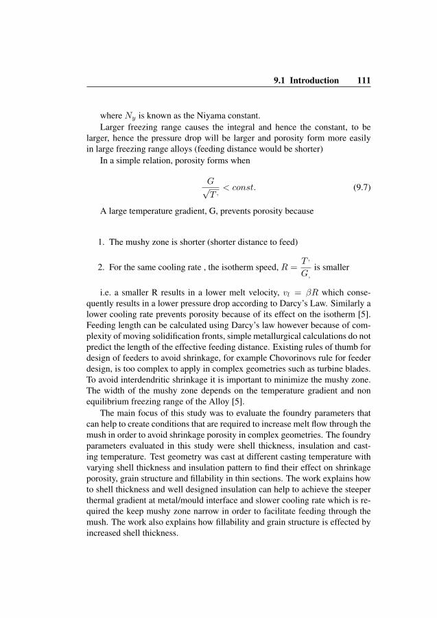

112 Paper C
9.2 Experimental workIn this experimental work a typical turbine blade geometry for an industrial gasturbine was selected, with chord length of 89 mm (3.50”), leading edge thick-ness 0.56 mm (0.022”) and trailing edge thickness 1.05 mm (0.041”). Thecluster was designed to optimize fluid flow in the cavity based on results ofa number of simulations. The cluster design selected for experimental workis shown in Figure 9.2. Simulations were performed using the commercialsoftware package Nova Flow & Solid CVTM[6]. For reliable input from simu-lation, thermal properties for the shell material were measured in order to pro-duce data for simulation software. Thermo-physical properties for the Udimet500TM, the cast alloy were calculated with JMatPro, [7], and are shown in table9.1. fl represent fraction liquid during solidification, ρ density of the metal,κ thermal conductivity, H enthalpy and µ viscosity. Well established princi-ples for gating design from previous work [2] [8] were considered to design acluster.
T (◦C) fl (−) ρ (kg/m3) κ (W/m◦C) H (J/kg◦C) µ (Pa s)
1400 7152 728 6.51375 7171 720 6.81350 1 7230 8020 7.21325 0.40 7355 3275 7.71300 0.28 7425 2404 8.31275 0.10 7464 1317 9.11250 0.09 7490 996 101225 0.07 7508 1099 10.81200 0.05 7526 30.5 781 11.71150 0 7526 30.5 781 11.61100 7588 28.8 627 12.91000 7767 26.2 845900 7726 24.2 722800 7777 22.6 569700 7821 21.1 553600 7863 19.6 535500 7903 18.1 517400 7941 16.6 500300 7977 15 484200 8010 13.4 467100 8042 11.8 44925 8064 10.5 433
Table 9.1: Thermo-physical properties for the Udimet 500TMused in simula-tion.
The ceramic shell material used for the experimental work was water basedcollidal silica. The inner most layer consisted of CoAl2o4 as a grain refiner andcolloidal silica bound ZrSiO4 with Alumina oxide as stucco. Priming layersconsisted of colloidal silica with a 325-200 mesh zircon flour. Alumina with a
9.2 Experimental work 113
Figure 9.2: Tree design for blade casting, all dimensions in millimetres
mesh size of 90-54 was used as stucco. For back up layers colloidal silica witha 200 mesh aluminium silicate slurry was used. 16-30 mesh aluminium sili-cate was used as stucco in backup layers. The shell properties were measuredempirically. The specific heat capacity Cp of ceramic mould was measuredwith a differential scanning calorimeter Netzsch STA 404CTMequipment at atemperature range between 25◦C to 1200◦C (77 - 2192◦F) as shown in Figure9.5 (a).
In order to measure thermal diffusivity α of the mold, measurements weretaken at temperature intervals 900 - 1300◦C (1652 - 2372◦F) using a Laser-Flash Netzsch LFA 427/4/GTM. The values of thermal diffusivity with respectto temperature are shown in Figure 9.5 (b). Density was measured in a temper-ature range between 25◦C (77◦F) and 1200◦C (2192◦F) using a Netzsch DIL402C/4/GTMdilatometer and the values of density vs. temperature are shown inFigure 9.5 (c). Thermal conductivity was calculated from thermal diffusivity,specific heat and density measurements [9].
λ(T ) = α(T )ρcp(T ) (9.8)
Various patterns and thickness of insulation were applied to control heat

114 Paper C
0 200 400 600 800 1000 12000,70
0,75
0,80
0,85
0,90
0,95
1,00
1,05
1,10
Spe
cific
Hea
t (cp
, J/g
K)
Temperature (°C)
Specific Heat
(a) Specific heat of shell measured atdifferent temperatures
0 200 400 600 800 1000 12000,46
0,48
0,50
0,52
0,54
0,56
0,58
0,60
0,62
0,64
Ther
mal
diff
usiv
ity (m
m2/
s)
Temperature (°C)
Thermal diffusivity
(b) Thermal diffusivity of shell measured atdifferent temperatures
0 200 400 600 800 1000 1200 1400
2,450
2,455
2,460
2,465
2,470
2,475
2,480
2,485
2,490
2,495
Den
sity
(g/c
m3)
Temperature (°C)
Density
(c) Density of shell measured atdifferent temperatures
0 200 400 600 800 1000 1200
1,10
1,15
1,20
1,25
1,30
1,35
1,40
1,45
Ther
mal
Con
duct
ivity
(W/(m
*K))
Temperature (°C)
Thermal Conductivity
(d) Thermal conductivity of shell measuredat different temperatures
Figure 9.3: Thermo-physical properties of the shell used in simulation
Insulation type Temp. 1500◦C (2732◦F) Temp. 1520◦C (2768◦F) Temp. 1540◦C (2804◦F) Temp. 1560◦C (2840◦F)
Type 1 9 and 11 mm Shell 9 and 11 mm Shell 9 and 11 mm Shell 9 and 11 mm ShellType 2 9 and 11 mm Shell 9 and 11 mm Shell 9 and 11 mm Shell 9 and 11 mm ShellType 3 9 and 11 mm Shell 9 and 11 mm Shell 9 and 11 mm Shell 9 and 11 mm ShellType 4 9 and 11 mm Shell 9 and 11 mm Shell 9 and 11 mm Shell 9 and 11 mm ShellType 5 9 and 11 mm Shell 9 and 11 mm Shell 9 and 11 mm Shell 9 and 11 mm ShellType 6 9 and 11 mm Shell 9 and 11 mm Shell 9 and 11 mm Shell 9 and 11 mm ShellType 7 9 and 11 mm Shell 9 and 11 mm Shell 9 and 11 mm Shell 9 and 11 mm ShellType 8 9 and 11 mm Shell 9 and 11 mm Shell 9 and 11 mm Shell 9 and 11 mm Shell
Table 9.2: Design of experiments9mm=0.35” and 11mm=0.43”
flow and cooling rate in the airfoil. The intent was to control the solidificationrate and direction. Table 9.3 describes the different types of insulations pattern
9.3 Results 115
and thickness used in the casting trials.
Insulation type Explanation
Type 1 No insulation.Type 2 6 mm Complete air-foil.Type 3 12 mm Complete air-foil.Type 4 6 mm on bottom half at root side of air-foil and 12 mm on top half.Type 5 6 mm on bottom half at root side of air-foil and 12 mm on top half + 6 mm at tip shroud.Type 6 12 mm on bottom half at root side of air-foil and 6 mm on top half.Type 7 6 mm on 2/3 of bottom side at root of air-foil and 12 mm on 1/3 of top.Type 8 6 mm on 1/3 of bottom side at root of air-foil , 12 mm on middle and 18 mm on 1/3 of top.
Table 9.3: Insulation types and explanation.6 mm=0.24”, 12 mm=0.47” and 18 mm=0.71”
The casting trials were performed according to experimental set up pre-sented in Table 9.2. All castings were made in vacuum furnace. The time tocast (from preheat oven to pouring of tree) was kept constant for all the cast-ings. The vacuum level (7 ∗ 10−4 mbar) in the furnace was kept constant andthe castings conditions were kept as identical as possible.
9.3 ResultsTo find effect of shell thickness and insulation on shrinkage porosity and grainat different casting temperature, results of experiments were statistically anal-ysed using the commercially available statistical software, OriginProTM[10].For grain size evaluation, section closer to the root of the blade (the area whichis more prone to the large gain size) was cut and evaluated using optical mi-croscopy. Figure 9.4 shows the location of cut sections for microscopy. Thearea with large grains is measured by etching and manually measuring surfacearea of zone that is affected by coarse and columnar grains. The shrinkageporosity was manually measured from the X-ray films.
9.3.1 Effect of shell thickness on porosity and grain sizeShell thickness was observed to have very significant effect on shrinkage. Itwas possible to reduce size of shrinkage by increasing shell thickness. Theeffect of varying shell thickness on porosity and grain size at different tem-perature is presented in the graphs in Figure 9.8 (a) and (b). It was observedthat increased shell thickness resulted in less shrinkage as shown in 9.8 (a).The graph shows the size of shrinkage at chord-tip shroud junction cast at four

116 Paper C
Figure 9.4: Sample location for micro structure evaluation
different casting temperature in ceramic shell made in two different thickness.Size of shrinkage at the chord-tip shroud junction dropped significantly by in-creasing shell thickness (by adding more layer of ceramic during shell buildingprocess), however effect of increased shell thickness on grain size was not sig-nificant as shown in 9.8 (b) and 9.5.
(a) Grain size at leading edge of theblade cast with 9 mm shell (0.35”)
(b) Grain size at leading edge of theblade cast with 11 mm shell (0.43”)
Figure 9.5: Grain size at selected section shown in figure9.4 cast at 1560◦C(2840◦F)
9.3 Results 117
9.3.2 Effect of temperature on shrinkage and grain size
Geometries were cast at different temperatures to observe the effect of castingtemperature on porosity and grain size. The best results in terms of shrinkagewere observed at 1560◦C (2840◦F) as shown in the X-ray film in Figure 9.7however a coarse grain structure was observed at the root of blade as shown inFigure 9.6. Graph in figure 9.8 (a) shows that at lower casting temperature, ı.e1500◦C (2732◦F), very large pores appeared at the chord-tip shroud junction.With an increase in casting temperature, size of shrinkage pore at chord-tipshroud junction dropped, however, an increase in grain size at the root of bladewas observed as shown in figure 9.8 (b). Graph in figure 9.8 (b) shows theincrease in area affected by larger grains at the root of blade as a result ofincrease in casting temperature.
(a) Grain structure in leading edgeof blade at cast temperature 1560◦C(2840◦F)
(b) Grain structure in leading edgeof blade at cast temperature 1520◦C(2768◦F)
Figure 9.6: Effect of temperature on grain size in a selected section shown infigure9.4
It was possible to obtain a fine-grain microstructure at lower casting tem-peratures, for example, 1520◦C (2768◦F) and 1500◦C (2732◦F) however largeshrinkage at chord-tip shroud junction appeared at all these temperatures inuninsulated clusters with both 9 mm (0.35) and 11 mm (0.43”) shell, however,at 11 mm (0.43”) size of shrinkage was significantly small as shown in 9.8 [a].It can be seen in X-ray images of these blades shown in Figure 9.7 that theextent of shrinkage increases with decreasing casting temperature.

118 Paper C
Figure 9.7: Indication of porosity at different cast temperatures A) 1500◦C(2732◦F), B)1520◦C (2768◦F), C) 1540◦C(2804◦F), D) 1560◦C (2840◦F)
1500 1520 1540 15602
4
6
8
10
12
14
Siz
e of
por
ous
zone
(Squ
are
mm
)
Temperature (°C)
9mm shell11mm shell
(a) Effect of casting temperature onPorosity at two different shell thickness
1500 1520 1540 1560
0
200
400
600
800
Are
a ef
fect
ed w
ith la
rger
gra
ins
(Squ
are
mm
)
Casting temperature (°C)
9mm shell11mm shell
(b) Effect of casting temperature ongrain size at two different shell thickness
0 1 2 3 4 5 6 7 8 9
0
5
10
15
20
25
Siz
e of
por
ous
zone
(Squ
are
mm
)
Insulation type (Type and location)
1500 C1520 C1540 C1560 C
(c) Effect of insulation type on size ofporosity at different temperatures
0 1 2 3 4 5 6 7 8 9
0
200
400
600
800
1000
1200
Are
a ef
fcte
d by
larg
er g
rain
s (S
quar
e m
m)
Insulation Type (Type and Location)
1500 C1520 C1540 C1560 C
(d) Effect of insulation type ongrain size at different temperatures
Figure 9.8: Effect of casting parameters on shrinkage porosity and grain size
9.4 Discussion 119
9.3.3 Effect of insulation on porosity and grain sizeTo investigate the effect of insulation on the shrinkage porosity inside the air-foil, only air-foils were insulated. Variation in insulations patterns and thick-ness significantly affected the size of the porosity as shown in Figure 9.8 (c).Types of insulations are explained in table 9.3. In uninsulated geometries,shrinkage at chord-tip shroud junction appeared at all casting temperatures,however, similar to pattern appeared in section 3.1, size of shrinkage droppedwith an increase in casting temperature. It was observed that adding thickerinsulation, for example, insulation type 3 can help to minimize the size ofshrinkage pore, however, it resulted in large grains at the root of blade. Graphin 9.8 (d) shows the effect of insulation on the size of area affected by largergrains close to the root of blade.
Insulation at blade geometry did not effect the size of grains at lower cast-ing temperature,ı.e. 1500 ◦C (2732◦F), however, with an increasing castingtemperature, large grain appeared at the root of blade. The extent of areaaffected by large grains was dependent on the thickness and location of theinsulation as explained in table 9.3.
To further determine effect of insulation on fillability and grain size, trialswere also performed using insulation at the feeder and in-gates. It was observedthat if feeder and in-gates are insulated, larger grains can appear at the rootof blade ı.e. adjacent to the feeder even at low temperature, for example, at1500◦C (2732◦F). No significant effect of insulated in-gates and feeders wasobserved in terms of fillablity.
9.4 DiscussionCasting temperature, insulation and shell thickness appeared to be key pro-cess parameters for eliminating shrinkage porosity, missruns and non-uniformgrain structure as shown in graphs 9.8 (a), (b), (c) and (d). It was observedthat eliminating shrinkage and missruns while maintaining a fine-grained mi-cro structure required a trade-off. At higher temperature i.e. 1560◦C (2840◦F)shrinkage porosity was completely avoidable due the the prolonged feedingof melt as shown in figure 9.7. However high casting temperature resulted incoarse grains at the root of the blade due to higher thickness at root and highheat mass from the adjacent feeding arm. Figure 9.5 shows the large grains atthe root of the blade cast at 1560◦C (2840 ◦F). At lower casting temperature, e.g. 1520◦C (2768◦F) shrinkage porosity was avoidable by increasing theshell thickness without increasing the size of grains at the root of the blade as

120 Paper C
shown in 9.8 (a) and (b), where effect of casting temperature on grain size andporosity at two shell thickness is presented. Increased shell thickness as well asthe application of insulation to the shell also serves to decrease the cooling rateand thereby to limit dendrite arm length and thus the width of mush. The bestresults were obtained by minimizing cast temperature, adding insulation thatallows faster cooling at the root of blade to limit grain size while slowing thecooling in thin sections which along with increased shell thickness control thewidth of mush. Figure 9.8 (c) and (d) describes the effect of different insulationpatterns on grain size and shrinkage porosity.
Increasing shell thickness and thus increasing the capacity of the mould toabsorb heat at initial phase of solidification lead to a steeper thermal gradient atthe metal/mould interface [11]. A steeper thermal gradient hindered the growthof dendrite arms and improved the fillability in the thin sections and feed ofmetal to the shrinkage pores. However, no significant effect of increased shellthickness on the grain size was observed which can be attributed to the fact thateffect of shell thickness on thermal gradient is for very short period of time, i.e.one or two initial seconds of solidification process after mould filling. Theseinitial few seconds of solidification are very critical for dendrite growth [11]and thus for shrinkage porosity in thin sections of the blade, however not atthe time scale where grain formation occurs, especially at the root of bladewhere cooling rate is slower due to the adjacent feeder and thus extra heatmass. Grain size appeared to be dependent on available heat mass and coolingrate. At higher casting temperature, presence of extra heat mass above the rootof the airfoil resulted in much slower cooling rate as compared to thin sectionsand thus larger grains in the root of the blade. The effect of casting temperatureon grain size in a section shown in in figure 9.4 is presented in graph 9.8 (b). Inthe presence of steep thermal gradient, an insulation pattern that allows slowercooling in the thin section while faster cooling in thicker section can help toavoid shrinkage porosity as well as uneven grain structure.
9.5 Conclusion
It has been observed that the thickness of the ceramic shell strongly influencesshrinkage. The heat absorbing capacity of ceramic is determined by shell thick-ness, which is critical for casting of thin, complex shapes.
In thinner sections and at sharp junctions, the heat absorbing capacity isimportant due to its effect on the heat transfer coefficient and the thermal gra-dient in the metal adjacent to the mould wall. Increasing the heat absorbing
9.5 Conclusion 121
capacity of ceramic shell helps to maintain a high thermal gradient betweenmelt and mold for a longer time interval. The width of mushy zone decreaseswith increasing thermal gradient making possible feed of metal to shrinkagepores.
Adding insulation at thinner sections also slows the cooling rate which con-sequently minimizes the dendrite length resulting in a more planar solidifica-tion front. The conditions achieved through the higher thermal gradient andslower cooling rate keeps the width of mush shorter which allows metal feedthrough growing dendrite arms for a longer distance and thus helps to reduceshrinkage not only at points where solidification front meets but also betweenthe growing dendrites.
AcknowledgementThe authors would like to express their sincere gratitude to Jon A. Dantzigfor helpful discussions. We also acknowledge Foundry Research Institute inKrakow for conducting test on ceramic shell properties as part of joint studywithin CleanSky-LEAN project. Authors also thankfully acknowledge the fi-nancial support of the Innofacture program at Malardalen Hogskola fundedthrough KK-Stiftelsen.

Bibliography
[1] Hasse Fredriksson and Ulla Akerlind. Materials processing during cast-ing. Wiley, 1st edition edition, 2006.
[2] P R. Beeley and R F. Smart. Investment Casting. The Institute of Materi-als, 2nd edition edition, 1995.
[3] J A. Dantzig and M.Rappaz. Solidification. FPFL Press, 1st edition edi-tion, 2009.
[4] Kent D.Carlson and C.Beckermann. Prediction of shrinkage pore volumefraction using dimensionless niyama criterion. Metallurgical and Mate-rials Transactions A, 40A:163–175, 2009.
[5] D A. Porter and K E. Easterling. Phase Transformations in Metals andAlloys. V.N.R. (International) Co.Ltd, 1st edition edition, 1981.
[6] Nova Flow&Solid, version 4.6r3, (2012).
[7] JMatPro SENTES.
[8] D Z. Li, John Campbell, and Y Y. Li. Filling system for investmentcast ni-base turbine blades. Journal of Material Processing Technology,148:310–316, 2004.
[9] C H. Konrad, M. Brunner, K. Kyrgyzbaev, R. Volkl, and U. Glatzel. De-termination of heat transfer coeffecient and ceramic mold material pa-rameters for alloy in738lc investment castings. Journal of Materials Pro-cessing Technology, 211:181–186, 2011.
[10] Origin Pro, OriginLab, Northampton, MA.
Bibliography 123
[11] Hasse Fredriksson and Ulla Akerlind. Solidification and crystallizationprocessing in metals and alloys. Wiley, 1st edition edition, 2012.