Embed Size (px)
Citation preview
USER MANUAL
Newgen Software Technologies Ltd
A-6, Satsang Vihar Marg, Qutab Institutional Area
New Delhi - 110067, INDIA
Tel: 91-11-40770100, 26964733, 26963571
Fax: +91-11-26856936
E-mail: [email protected]
February – 2020
iBPS
PROCESS DESIGNER
INTERFACE OF PROCESS DESIGNER
Interface of Process Designer Page 2
Disclaimer This document contains information proprietary to Newgen Software Technologies Limited. User
may not disclose or use any proprietary information or use any part of this document without
written permission from Newgen Software Technologies Limited.
Newgen Software Technologies Limited makes no representations or warranties regarding any
software or to the contents or use of this manual. It also specifically disclaims any express or
implied warranties of merchantability, title, or fitness for any particular purpose. Even though
Newgen Software Technologies Limited has tested the hardware and software and reviewed the
documentation, it does not guarantee or imply that this document is error free or accurate
regarding any particular specification. As a result, this product is sold as it is and user, the
purchaser, is assuming the entire risk as to its quality and performance. Further, Newgen Software
Technologies Limited reserves the right to revise this publication and make changes in its content
without any obligation to notify any person, of such revisions or changes. Newgen Software
Technologies Limited authorizes no Newgen agent, dealer or employee to make any modification,
extension, or addition to the above statements.
Newgen Software Technologies Limited has attempted to supply trademark information about
company names, products, and services mentioned in this document. Trademarks indicated below
were derived from various sources.
Copyright © 2020 Newgen Software Technologies Ltd. All Rights Reserved.
No part of this publication may be reproduced and distributed without the prior permission of:
Newgen Software Technologies Limited,
A-6, Satsang Vihar Marg, Qutab Institutional Area,
New Delhi - 110067
INDIA

Interface of Process Designer Page 3
TABLE OF CONTENTS
1 Introduction ........................................................................................................................................... 7
2 Getting Started....................................................................................................................................... 8
2.1 Accessing Process Designer ........................................................................................................................... 8
2.2 Process Designer Interface ............................................................................................................................ 9
3 Process Designer Designing Interface ................................................................................................... 11
3.1 Project Tree ................................................................................................................................................ 11
3.2 Process Tree ............................................................................................................................................... 15
3.2.1 Process View ...................................................................................................................................... 16
3.2.1.1 Add Milestone................................................................................................................................ 17
3.2.1.2 Delete Milestone ............................................................................................................................ 18
3.2.1.3 Add Workdesk................................................................................................................................ 19
3.2.1.4 Delete Workdesk ............................................................................................................................ 20
3.2.2 Business Object .................................................................................................................................. 21
3.2.2.1 Add Complex Variable .................................................................................................................... 21
3.2.2.2 Import Complex Variable ................................................................................................................ 22
3.2.2.3 Delete Complex Variable ................................................................................................................ 25
3.2.2.4 Add Fragment ................................................................................................................................ 28
3.2.2.5 View Complex Variable Properties .................................................................................................. 31
3.2.3 Business Variables .............................................................................................................................. 33
3.2.3.1 Add Queue Variable ....................................................................................................................... 33
3.2.3.2 View Business Variable Properties .................................................................................................. 35
3.2.4 Form List ............................................................................................................................................ 36
3.2.4.1 Add Form ....................................................................................................................................... 36
3.2.4.2 Upload Form .................................................................................................................................. 38
3.2.4.3 View Form...................................................................................................................................... 39
3.2.4.4 Delete Form ................................................................................................................................... 41
3.2.4.5 Rule Based Forms ........................................................................................................................... 43
3.2.5 Form Fragments for NGF form ............................................................................................................ 47
3.2.5.1 Add Form Fragment ....................................................................................................................... 47
3.2.5.2 View Form Fragment ...................................................................................................................... 48
3.2.5.3 Delete Form Fragment ................................................................................................................... 49
3.2.6 Tasks .................................................................................................................................................. 49
3.2.6.1 Add a Task...................................................................................................................................... 50
3.2.6.2 Delete a Task.................................................................................................................................. 51
3.3 Process View .............................................................................................................................................. 52
3.4 Properties View .......................................................................................................................................... 52

Interface of Process Designer Page 4
3.5 Chat............................................................................................................................................................ 60
3.5.1 Add User ............................................................................................................................................ 60
3.5.2 Start Chat ........................................................................................................................................... 65
3.5.3 Delete User ........................................................................................................................................ 67
3.5.4 Add Group.......................................................................................................................................... 68
3.5.5 Delete Group ...................................................................................................................................... 69
3.5.6 View Saved Conversations .................................................................................................................. 70
4 Create Project and Process ................................................................................................................... 71
4.1 Create Project ............................................................................................................................................. 71
4.2 Create Process ............................................................................................................................................ 73
5 Design Process ..................................................................................................................................... 75
5.1 Views.......................................................................................................................................................... 75
5.1.1 Abstract View ..................................................................................................................................... 75
5.1.2 BPMN View ........................................................................................................................................ 76
5.2 Tool Box ..................................................................................................................................................... 77
5.2.1 Task Templates .................................................................................................................................. 79
5.2.2 Start Events ........................................................................................................................................ 80
5.2.3 Activities ............................................................................................................................................ 81
5.2.4 Intermediate Events ........................................................................................................................... 82
5.2.5 Gateways ........................................................................................................................................... 84
5.2.6 End Events ......................................................................................................................................... 85
5.2.7 Artifacts ............................................................................................................................................. 86
5.2.8 Swim Lanes ........................................................................................................................................ 86
6 Menu Bar Options ................................................................................................................................ 88
6.1 Actions ....................................................................................................................................................... 88
6.2 Save As ....................................................................................................................................................... 89
6.3 Version ....................................................................................................................................................... 90
6.4 Refresh ....................................................................................................................................................... 90
6.5 Share .......................................................................................................................................................... 90
6.6 Options....................................................................................................................................................... 91
6.6.1 Constants ........................................................................................................................................... 92
6.6.2 Define Tables ..................................................................................................................................... 93
6.6.3 External Variables............................................................................................................................. 101
6.6.4 Complex Types ................................................................................................................................. 102
6.6.5 Queue Variables ............................................................................................................................... 106
6.6.6 Search Variables ............................................................................................................................... 120
6.6.7 Export/Import Data .......................................................................................................................... 124
6.6.8 Define Variable Alias......................................................................................................................... 132

Interface of Process Designer Page 5
6.7 Tools ........................................................................................................................................................ 134
6.7.1 Include Window ............................................................................................................................... 136
6.7.2 ToDo List .......................................................................................................................................... 137
6.7.3 Documents ....................................................................................................................................... 142
6.7.4 Catalog Definition ............................................................................................................................. 143
6.7.5 Exception ......................................................................................................................................... 166
6.7.6 Trigger ............................................................................................................................................. 169
6.7.7 Register Template ............................................................................................................................ 185
6.7.8 Register Window .............................................................................................................................. 189
6.7.9 Register Trigger ................................................................................................................................ 190
6.7.10 Property Association ........................................................................................................................ 191
6.7.11 Default Queues for Activity ............................................................................................................... 192
6.7.12 Register SAP Details .......................................................................................................................... 193
6.7.13 Register BRT Details (For Registered Process Only)............................................................................ 196
6.7.14 Global Task Template ....................................................................................................................... 197
6.7.15 Export/Import Template ................................................................................................................... 213
6.8 Admin....................................................................................................................................................... 218
6.8.1 Deploy ............................................................................................................................................. 218
6.8.2 Validate Process ............................................................................................................................... 219
6.8.3 Maker Checker ................................................................................................................................. 220
6.8.4 Form View ........................................................................................................................................ 224
7 Deploy Process ................................................................................................................................... 226
7.1 Deploy Process ......................................................................................................................................... 226
7.2 Enable/Disable Process ............................................................................................................................. 227
7.2.1 Enable Process ................................................................................................................................. 227
7.2.2 Disable Process ................................................................................................................................ 228
8 Check-in/Check-out Process ............................................................................................................... 230
8.1 Check Out ................................................................................................................................................. 230
8.2 Check In .................................................................................................................................................... 235
8.3 Save As Local ............................................................................................................................................ 237
9 Export Process from Registered Process ............................................................................................ 240
10 Import/Export Process from Local Process ......................................................................................... 241
10.1 Import Process.......................................................................................................................................... 241
10.2 Export Process .......................................................................................................................................... 243
11 Delete Project/Process ....................................................................................................................... 245
11.1 Delete Project ........................................................................................................................................... 245
11.2 Delete Process .......................................................................................................................................... 246

Interface of Process Designer Page 6
12 Rename Project .................................................................................................................................. 249
13 Audit Trail for Project/Process ........................................................................................................... 250
14 Collaborative Process ......................................................................................................................... 252
14.1 Share Process ........................................................................................................................................... 252
14.2 Unshare Process ....................................................................................................................................... 255
14.3 Leave Sharing ........................................................................................................................................... 256
14.4 Request Lock ............................................................................................................................................ 257
14.5 Grant Lock ................................................................................................................................................ 259
14.6 Release Lock ............................................................................................................................................. 262
14.7 Revoke Lock .............................................................................................................................................. 264
14.8 Chat.......................................................................................................................................................... 265
15 Process Variants ................................................................................................................................. 266
15.1 Define Process Variants ............................................................................................................................ 266
15.2 Create Process Variants ............................................................................................................................ 266
15.3 Add Variants ............................................................................................................................................. 269
15.3.1 Registration ...................................................................................................................................... 269
15.3.2 Variable(s) ........................................................................................................................................ 270
15.3.3 Document(s) .................................................................................................................................... 272
15.3.4 Association(s) ................................................................................................................................... 273
15.3.5 Events .............................................................................................................................................. 275
15.4 Modify Variants ........................................................................................................................................ 277
15.4.1 Registration ...................................................................................................................................... 277
15.4.2 Variable(s) ........................................................................................................................................ 278
15.4.3 Document(s) .................................................................................................................................... 278
15.4.4 Association(s) ................................................................................................................................... 279
15.4.5 Events .............................................................................................................................................. 280
15.5 Delete Variants ......................................................................................................................................... 281
15.6 Enable Variants ......................................................................................................................................... 281
15.7 Audit Trail ................................................................................................................................................. 281
16 List of Abbreviations .......................................................................................................................... 282

Interface of Process Designer Page 7
1 Introduction Introduction to iBPS Process Designer
iBPS (Intelligent Business Process Suite) Process Designer is a graphical tool that provides designing
of business processes in a flow chart fashion with clear indication of the worksteps, conditions, and
sequences in which tasks must be performed from initiation to completion. It enables users to
design workflow processes with steps in series or in parallel or combination of both. It enables
defining all worksteps in a process, their relationship, various processing rules, actions, work to be
performed, and so on. It also provides compiled reports to measure correctness of the definition.
Interface of Process Designer Page 8
2 Getting Started
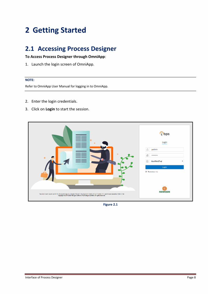
2.1 Accessing Process Designer To Access Process Designer through OmniApp:
1. Launch the login screen of OmniApp.
NOTE:
Refer to OmniApp User Manual for logging in to OmniApp.
2. Enter the login credentials.
3. Click on Login to start the session.
Figure 2.1
Interface of Process Designer Page 9
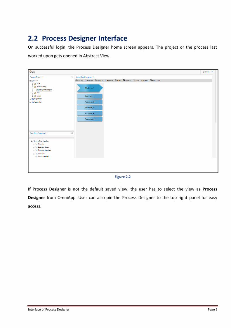
2.2 Process Designer Interface On successful login, the Process Designer home screen appears. The project or the process last
worked upon gets opened in Abstract View.
Figure 2.2
If Process Designer is not the default saved view, the user has to select the view as Process
Designer from OmniApp. User can also pin the Process Designer to the top right panel for easy
access.
Interface of Process Designer Page 10
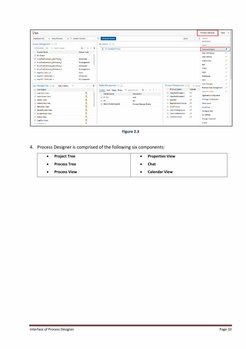
Figure 2.3
4. Process Designer is comprised of the following six components:
Project Tree
Process Tree
Process View
Properties View
Chat
Calendar View

Interface of Process Designer Page 11
3 Process Designer Designing Interface
3.1 Project Tree Project Tree component shows the projects in the form of:
Local Project: Local project is the archiving of the projects and its processes from the designer
of Process Designer.
Registered Project: Registered project is the archiving of projects and its processes from iBPS.
Applications: Web based portal applications. For getting information about Applications, please
refer to the “Application Development Guide” document.
Figure 3.1
List of Local Projects are visible, in the following screen:-

Interface of Process Designer Page 12
Figure 3.2
List of Registered Projects are visible, in the following screen:-
Figure 3.3

Interface of Process Designer Page 13
To create a new Project, right click on Local, if you have rights to create a new Project, you will see
an option to create a new Project as shown below:
Figure 3.4
Once, user clicks on “Create Project”, user will see a pop-up as shown below, in which user can
enter the Project Name:
Figure 3.5
Once, user types out a name and clicks on tick mark symbol, a project with the provided name will
be created under the Project Tree.
User can right-click on the created Project, and then user will see an option to create a menu with
options, as per the rights given to the user as shown below:

Interface of Process Designer Page 14
Figure 3.6
If user has rights to create the Process, and user clicks on Create Process, user will see the below
pop-up. Here, user should use the default option of Generic, enter the Process Name and click on
tick mark icon to create a new Process. If user selects RPA, in the process type, then user can either
keep the default activity Excel or change it to another type. RPA process types are detailed out in
separate document “RPA Process Guide”.
Figure 3.7
As soon as a Process gets created, the right panel will show the created process details as shown
below:

Interface of Process Designer Page 15
Figure 3.8
3.2 Process Tree The Process Tree at the bottom left is used to display the various attributes within a process.
As user selects process from the Project Tree, system displays associated Process Tree for the
selected process.
Figure 3.9

Interface of Process Designer Page 16
The Process is divided in the following ways:
Process: Displays process name, milestones and activities of the selected process.
Business Object: Displays all the complex variables in selected process.
Business Variables: Displays all the queue variables in selected process.
Form List: Displays all forms linked to the selected process.
Form Fragments: Displays all the form fragments linked to respective business objects in the
selected process.
Tasks: Displays all the tasks defined for the selected process.
3.2.1 Process View Process contains process name, milestones and activities. Here user can add/delete milestone and
add/delete workdesk.
Figure 3.10

Interface of Process Designer Page 17
3.2.1.1 Add Milestone To Add Milestone in Process Tree:
1. Go to Process Tree.
2. Select Process.
3. System displays Add Milestone icon.
Figure 3.11
4. Click on icon. System adds new milestone under Process.
5. By default a workdesk is added under added Milestone.
Figure 3.12
Interface of Process Designer Page 18
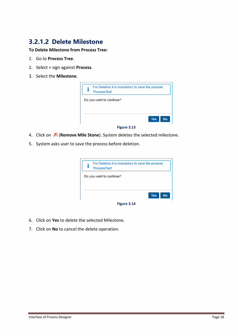
3.2.1.2 Delete Milestone To Delete Milestone from Process Tree:
1. Go to Process Tree.
2. Select + sign against Process.
3. Select the Milestone.
Figure 3.13
4. Click on (Remove Mile Stone). System deletes the selected milestone.
5. System asks user to save the process before deletion.
Figure 3.14
6. Click on Yes to delete the selected Milestone.
7. Click on No to cancel the delete operation.

Interface of Process Designer Page 19
3.2.1.3 Add Workdesk To Add Workdesk in Process Tree:
1. Go to Process Tree.
2. Select + sign against Process.
3. Select Milestone under which user want to add workdesk.
4. Click on (Add Activity). New workdesk is added under the selected Milestone.
Figure 3.15
Interface of Process Designer Page 20
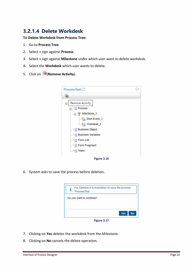
3.2.1.4 Delete Workdesk To Delete Workdesk from Process Tree:
1. Go to Process Tree.
2. Select + sign against Process.
3. Select + sign against Milestone under which user want to delete workdesk.
4. Select the Workdesk which user wants to delete.
5. Click on (Remove Activity).
Figure 3.16
6. System asks to save the process before deletion.
Figure 3.17
7. Clicking on Yes deletes the workdesk from the Milestone.
8. Clicking on No cancels the delete operation.

Interface of Process Designer Page 21
3.2.2 Business Object
Business Object contains all complex variables of the selected project. Here user can Add, Delete
and ImportComplex Variables, Add Form Fragments and View Complex Variable properties.
3.2.2.1 Add Complex Variable To Add Complex Variable in Process Tree:
1. Select Business Object.
Figure 3.18
2. Click on icon.
3. System displays Complex Types screen.

Interface of Process Designer Page 22
Figure 3.19
4. Add Complex Types. Refer section Complex Types for further details.
3.2.2.2 Import Complex Variable To Import Complex Variable:
1. Select Business Object.
Figure 3.20
Interface of Process Designer Page 23
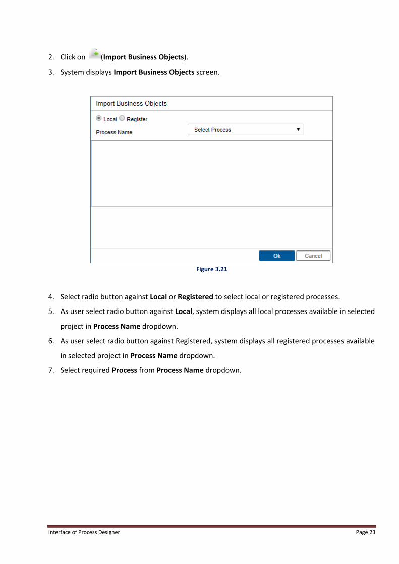
2. Click on (Import Business Objects).
3. System displays Import Business Objects screen.
Figure 3.21
4. Select radio button against Local or Registered to select local or registered processes.
5. As user select radio button against Local, system displays all local processes available in selected
project in Process Name dropdown.
6. As user select radio button against Registered, system displays all registered processes available
in selected project in Process Name dropdown.
7. Select required Process from Process Name dropdown.
Interface of Process Designer Page 24
Figure 3.22
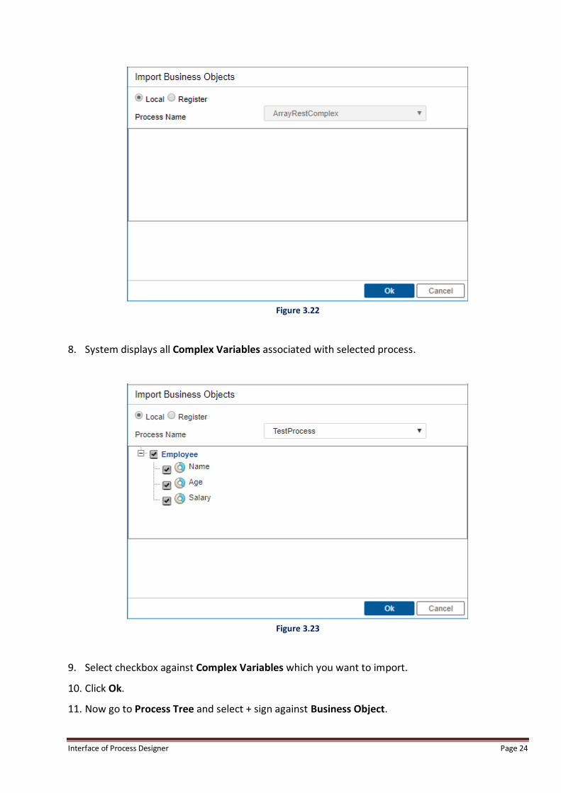
8. System displays all Complex Variables associated with selected process.
Figure 3.23
9. Select checkbox against Complex Variables which you want to import.
10. Click Ok.
11. Now go to Process Tree and select + sign against Business Object.
Interface of Process Designer Page 25
12. System adds Imported Complex Variables under Business Object.
Figure 3.24
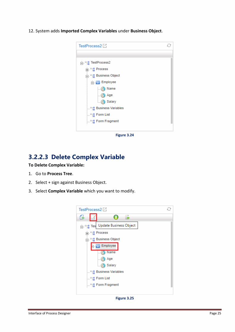
3.2.2.3 Delete Complex Variable To Delete Complex Variable:
1. Go to Process Tree.
2. Select + sign against Business Object.
3. Select Complex Variable which you want to modify.
Figure 3.25

Interface of Process Designer Page 26
4. Click on (Update Business Objects) icon.
5. System displays Complex Types screen. User can modify the complex structure from this
screen, if required, e.g. add new members to the structure.
Figure 3.26
6. Select Complex Variable and click on Delete button.
7. System deletes the selected Complex Variable.
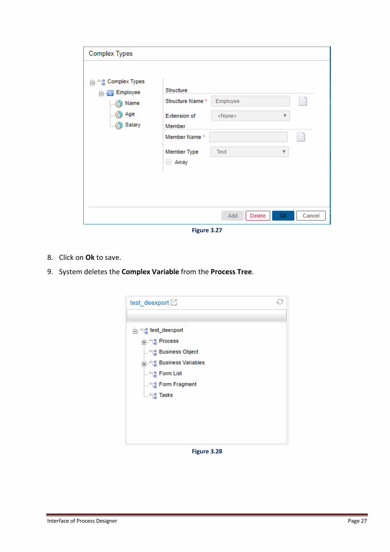
Interface of Process Designer Page 27
Figure 3.27
8. Click on Ok to save.
9. System deletes the Complex Variable from the Process Tree.
Figure 3.28

Interface of Process Designer Page 28
3.2.2.4 Add Fragment To Add Fragment in Process Tree:
1. Go to Process Tree.
2. Select + sign against Business Object.
3. Select Complex Variable for which user want to Add Fragment.
4. Click on (Define Fragment).
5. System asks user to enter Fragment Name.
Figure 3.29
NOTE:
Fragment name should be in English language only. Fragments are valid for NGforms only. iForms have sections, which
are imported and exported from iForm UI itself.
6. Enter Fragment Name and click on (Ok) icon.
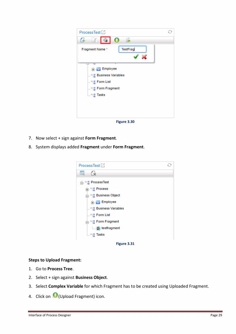
Interface of Process Designer Page 29
Figure 3.30
7. Now select + sign against Form Fragment.
8. System displays added Fragment under Form Fragment.
Figure 3.31
Steps to Upload Fragment:
1. Go to Process Tree.
2. Select + sign against Business Object.
3. Select Complex Variable for which Fragment has to be created using Uploaded Fragment.
4. Click on (Upload Fragment) icon.

Interface of Process Designer Page 30
5. Upload Fragment screen appears.
6. Click on Choose File button to select the form for uploading.
7. Enter Fragment Name. By default name of the form selected for upload gets loaded in
Fragment Name textbox.
Figure 3.32
NOTE:
Fragment name should be in English language only. Fragments are valid for NGforms only. iForms have sections, which
are imported and exported from iForm UI itself.
8. Click Ok to upload the selected form.
9. Now select + sign against Form Fragment.
10. System displays added/uploaded Fragment under Form Fragment.
Figure 3.33

Interface of Process Designer Page 31
3.2.2.5 View Complex Variable Properties To View Complex Variable properties:
1. Go to Process Tree.
2. Select + sign against Business Object.
3. Select + sign against Complex Variable for which user want to view its member’s properties.
4. Select Member for which user want to view properties.
5. Click on (Property) icon.
Figure 3.34
6. System displays Complex Variable Properties screen.

Interface of Process Designer Page 32
Figure 3.35
7. Click on Ok button to close the screen.

Interface of Process Designer Page 33
3.2.3 Business Variables Business Variables contain all Queue Variables of the selected project. Here user can add Queue
Variables and view their properties.
3.2.3.1 Add Queue Variable
To Add a Queue Variable:
1. Go to Process Tree.
2. Click on Business Variables.
3. Click on (Define Variable) to add New Business Variable.
Figure 3.36
4. System displays Variable Definition screen.

Interface of Process Designer Page 34
Figure 3.37
5. Add queue variable (Refer Queue Variables).
6. System displays added queue variables under Business Variables in Process Tree.
Figure 3.38

Interface of Process Designer Page 35
3.2.3.2 View Business Variable Properties To View Business Variable Properties in Process Tree:
1. Go to Process Tree.
2. Click on Business Variables.
3. Select + sign against Business Variables.
4. Select desired Business Variable to view its properties.
5. Click on (Property).
Figure 3.39
6. System displays Variable Properties screen displaying Name, Mapped Type, Type, Default
Value and Unbounded.
Figure 3.40

Interface of Process Designer Page 36
3.2.4 Form List Form List contains all forms associated with selected process. Here user can carry out the following
things:
Add Form
Upload Form
View Form
Delete Form
3.2.4.1 Add Form
To Add Form (viewable only in Desktop) in Process Tree:
1. Go to Process Tree.
2. Click on Form List.
3. Click on (Define Form) icon to add new form.
Figure 3.41
4. The following screen appears as shown:

Interface of Process Designer Page 37
Figure 3.42
5. Select Product Form to design iForm/NGF form or select Custom Form to deploy custom
designed form.
i. If Product Form option is selected:
a. Select the Form Type as iForm or NGF as per the requirement. iForm is the
recommended tool to be used. NGF form capability is available for backward
compatibility purpose. By default, iForm is shown as the selected option.
b. If you want to Design a separate form for mobile using an existing form, select Existing
Name.
c. Enter Form Name if you want to design an entirely new form.
NOTE:
User can also select any existing form name by selecting form name from the dropdown. As User selects checkbox
against Existing Name and selects form name from the dropdown, system displays selected form name in Form Name
field. In Existing Name, option user, can select an already existing form as the Mobile Option.
6. Click on (Ok) to save.
7. System displays added form under Form List.

Interface of Process Designer Page 38
Figure 3.43
3.2.4.2 Upload Form To Upload Form (Viewable in Desktop) in Process Tree:
1. Go to Process Tree.
2. Click on Form List.
3. Click on (Upload Form) icon to upload form.
4. “Please upload the form” screen appears.
Figure 3.44
5. Click on Choose File button to select file name for uploading.

Interface of Process Designer Page 39
6. Select the Form Type as NGForm or IForm as per the requirement. Make sure that the selected
form type matches to that of form type selected for uploading.
7. System displays uploaded Form Name in Form Name field.
8. User can also select any existing form name by carrying out following steps:
a. Select Existing Form Name check box.
b. Select Form Name from the dropdown.
c. System displays selected Form Name in Form Name field.
Figure 3.45
9. Click on Ok button. System displays uploaded form under Form List.
3.2.4.3 View Form To View iForm (Viewable in All Devices) in Process Tree:
1. Go to Process Tree.
2. Select + sign against Form List.
3. Select any added/uploaded form.
4. Click on (View Form) icon.
5. System displays Form in Process View.
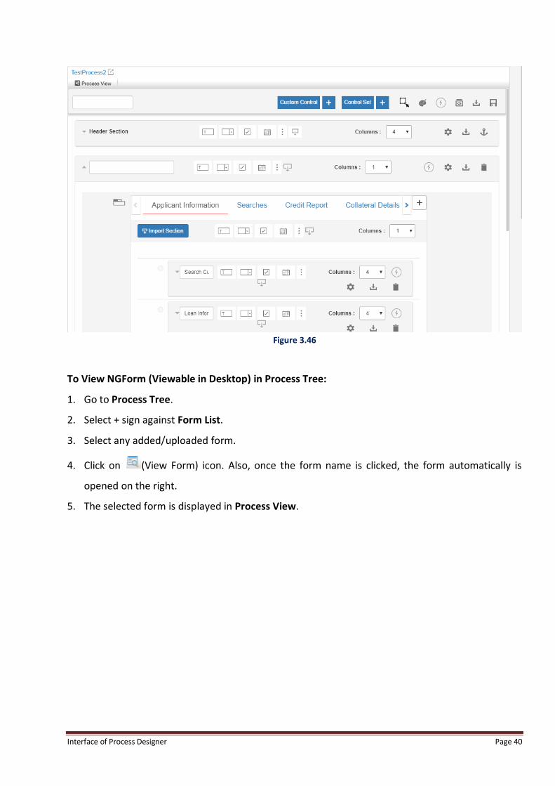
Interface of Process Designer Page 40
Figure 3.46
To View NGForm (Viewable in Desktop) in Process Tree:
1. Go to Process Tree.
2. Select + sign against Form List.
3. Select any added/uploaded form.
4. Click on (View Form) icon. Also, once the form name is clicked, the form automatically is
opened on the right.
5. The selected form is displayed in Process View.

Interface of Process Designer Page 41
Figure 3.47
3.2.4.4 Delete Form To Delete Form in Process Tree:
1. Go to Process Tree.
2. Select + sign against Form List.
3. Select any added/uploaded form.
4. Click on (Delete Form) icon.

Interface of Process Designer Page 42
Figure 3.48
5. System asks user to save the process before deletion.
Figure 3.49
NOTE:
This message box appears if the process is not already saved.
6. Clicking on Yes deletes the form from the Process Tree.
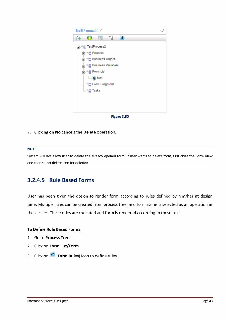
Interface of Process Designer Page 43
Figure 3.50
7. Clicking on No cancels the Delete operation.
NOTE:
System will not allow user to delete the already opened form. If user wants to delete form, first close the Form View
and then select delete icon for deletion.
3.2.4.5 Rule Based Forms
User has been given the option to render form according to rules defined by him/her at design
time. Multiple rules can be created from process tree, and form name is selected as an operation in
these rules. These rules are executed and form is rendered according to these rules.
To Define Rule Based Forms:
1. Go to Process Tree.
2. Click on Form List/Form.
3. Click on (Form Rules) icon to define rules.

Interface of Process Designer Page 44
Figure 3.51
4. The Rule List [Form] screen pops-up.
NOTE:
Form selected from rules take preference over the default form associated with the activity from property association.
By default if no rule is executed then the form associated with the activity in property association is rendered.
5. Click Add button to define rules.
6. The Rule Definition window pops-up.
7. Select Rule Condition.
8. Click on Add button.
9. The defined rule condition appears in the Condition List textbox.

Interface of Process Designer Page 45
Figure 3.52
NOTE:
For a defined rule condition, user can select only single form. It is not possible for a user to select multiple forms for a
defined rule conditions.
10. From Form dropdown list, select a form to which user want to apply the defined rule.
11. Click Add button. The selected form appears in the Operation List.
12. Click Ok.
13. The defined rule condition for the selected form appears in the Rule List [Form] screen.

Interface of Process Designer Page 46
Figure 3.53
14. User can modify or delete the defined rule from the respective Modify and Delete button.
NOTE:
Modify and Delete buttons are enabled after selecting a rule.

Interface of Process Designer Page 47
Figure 3.54
15. Click Ok to save and close the screen else click Cancel.
3.2.5 Form Fragments for NGF form
Form Fragment contains all form fragments associated with selected process. Here user can Add
and View form fragments.
Form Fragments allow user to extract common elements, such as a form header and footer, across
multiple forms and place them in a separate file called a "fragment".
3.2.5.1 Add Form Fragment Refer to Add Fragment section to learn how to add Form Fragment in a Process Tree

Interface of Process Designer Page 48
3.2.5.2 View Form Fragment To View Added Form Fragment in Process Tree:
1. Go to Process Tree.
2. Select + sign against Form Fragment.
3. Select Form Fragment Name and click on (View Fragment) icon.
4. System displays selected NGFForm Fragment in Process View.
Figure 3.55

Interface of Process Designer Page 49
3.2.5.3 Delete Form Fragment To Delete Form Fragment in Process Tree:
1. Go to Process Tree.
2. Select + sign against Form Fragment.
3. Select Form Fragment Name and click on (Delete Fragment) icon.
Figure 3.56
NOTE:
System will not allow the user to delete the already opened form fragment in Process View. If user wants to delete form
fragment, first close the Form View and then select delete icon for deletion.
3.2.6 Tasks
Tasks allow user to define ad-hoc activities for a process. These tasks can be defined and assigned
to users during runtime. Here user can add new tasks and delete the existing ones.
Interface of Process Designer Page 50
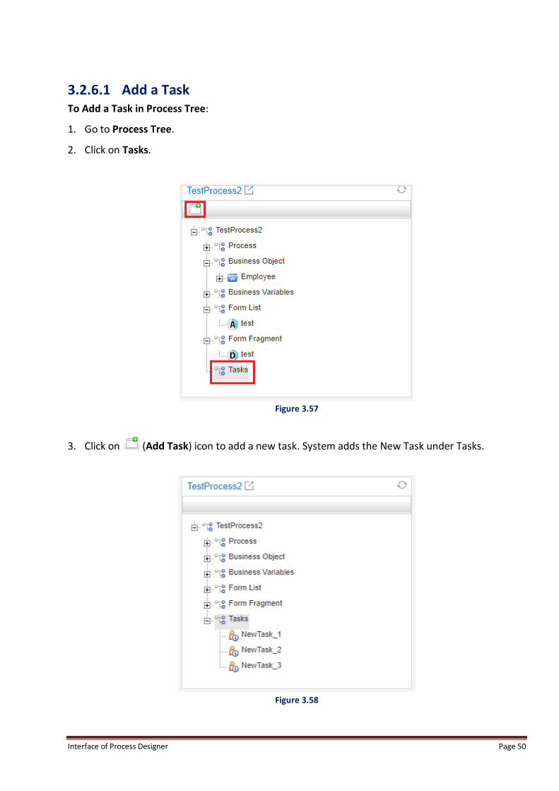
3.2.6.1 Add a Task To Add a Task in Process Tree:
1. Go to Process Tree.
2. Click on Tasks.
Figure 3.57
3. Click on (Add Task) icon to add a new task. System adds the New Task under Tasks.
Figure 3.58

Interface of Process Designer Page 51
3.2.6.2 Delete a Task To Delete a Task from Process Tree:
1. Go to Process Tree.
2. Click in + sign against Tasks to expand the folder tree.
3. Select the task which has to be deleted.
Figure 3.59
4. Click on (Remove Task) button to delete the selected task.
5. System asks user to save the process before deletion.
Figure 3.60
6. Clicking on Yes deletes the selected task from the Tasks folder.
7. Clicking on No cancels the delete operation.
Interface of Process Designer Page 52
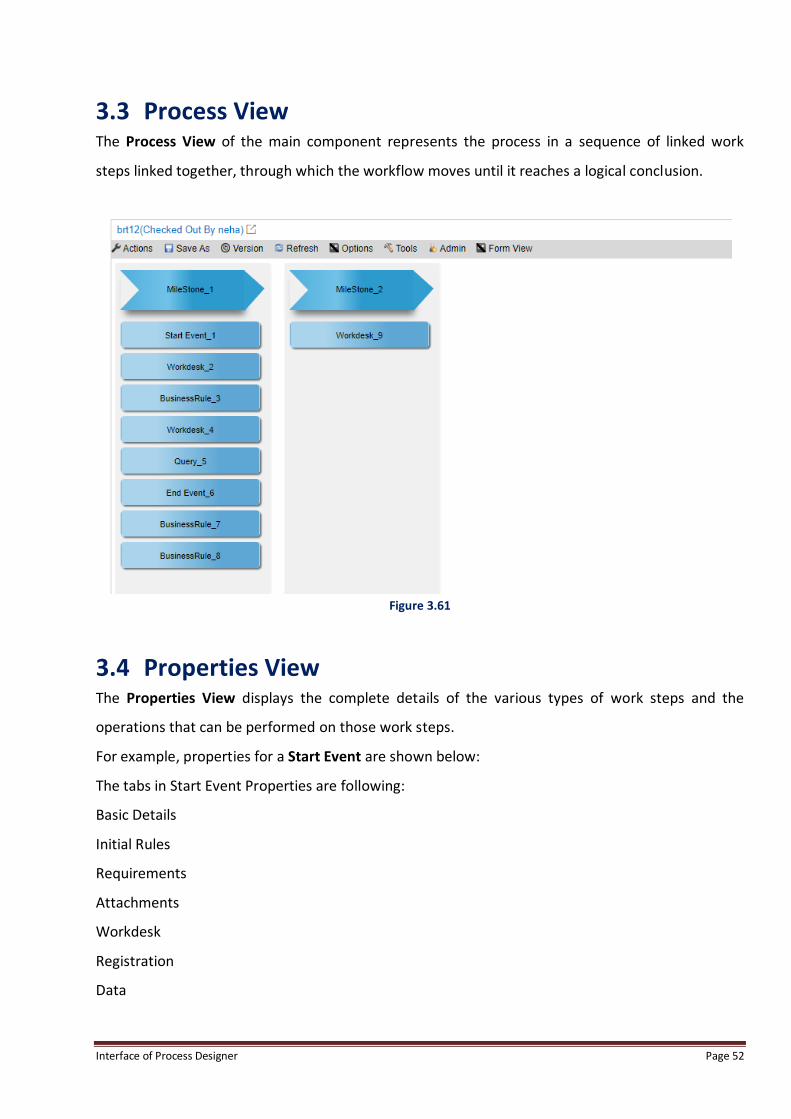
3.3 Process View The Process View of the main component represents the process in a sequence of linked work
steps linked together, through which the workflow moves until it reaches a logical conclusion.
Figure 3.61
3.4 Properties View The Properties View displays the complete details of the various types of work steps and the
operations that can be performed on those work steps.
For example, properties for a Start Event are shown below:
The tabs in Start Event Properties are following:
Basic Details
Initial Rules
Requirements
Attachments
Workdesk
Registration
Data

Interface of Process Designer Page 53
Figure 3.62
Start Event – Basic Details Tab
This tab contains following fields:
Activity – Displays the name of the activity.
Milestone – Displays the name of the milestone in which selected activity is placed.
Swimlane – Indicates the swimlane in which this activity has been placed.
Target Workstep – Allows user to select Target workstep to which control is transferred from
Start Event.
Form Enabled – To attach a form with the activity.
Mobile Enabled – Allows user to display selected activity on mobiles.
Form Name – Allows user to link the selected form with the selected activity. User need to
select checkbox against Form Enabled and select form name from the dropdown.
Calendar – Allows user to select Calendar as DEFAULT 24/7 or any user created calendar.
System displays two icons against Calendar field:
This icon is used to refresh the Calendar Field.
The Create Calendar option is shown, using which user can add new calendar.
This is used to search already created calendars.

Interface of Process Designer Page 54
To create a Calendar:
1. Click on (Create Calendar) icon.
2. System displays New Calendar screen.
Figure 3.63
3. Enter Name.
4. Enter Comments.
5. Select radio button against “Create new base calendar” or “Make a copy of”.
a. If user selects radio button against “Create new base calendar”, system will create a new
base calendar.
b. If user selects radio button against “Make a copy of”, system will ask user to select calendar
from the dropdown.
6. Select radio button against Global or Local.

Interface of Process Designer Page 55
a. If user selects radio button against Global, system displays the calendar globally.
b. If user select radio button against Local, system displays the calendar locally i.e. within a
process.
Figure 3.64
7. Click on OK button.
8. System displays Calendar screen.
9. Set Selected Date(s) to radio button as per requirement.
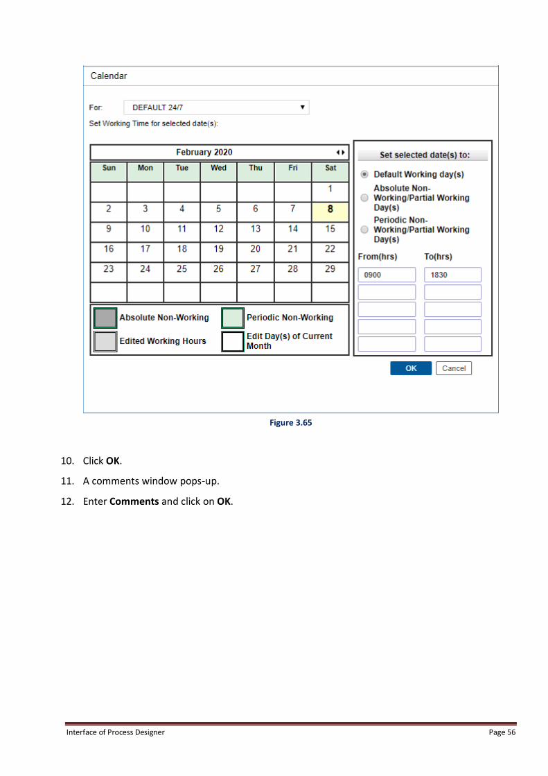
Interface of Process Designer Page 56
Figure 3.65
10. Click OK.
11. A comments window pops-up.
12. Enter Comments and click on OK.

Interface of Process Designer Page 57
Figure 3.66
13. User should now click on refresh icon to refresh the calendar list. System displays added
Calendar in Calendar dropdown in Properties View.
Figure 3.67

Interface of Process Designer Page 58
14. Enter the values in the given fields. The meaning of these fields are as follows:-
a. Custom Validation: Allows user to add code for custom validation for Start Event.
b. Cost (US$): Allows user to enter cost in US$.
c. Description: Allows user to enter description about Start Event activity.
d. Owner: Allows user to select user as Owner Name. As user click on icon, system opens
Select User screen:
Figure 3.68
More owners can be added by clicking on and removed by clicking on buttons
respectively.
e. Consultant: Allows user to select user as Owner Name. As user clicks on icon, system
opens Select User screen:

Interface of Process Designer Page 59
Figure 3.69
User can also add or remove rows by clicking on and buttons respectively.
f. System: Allows user to enter System Name. User can also add or remove rows by clicking on
and buttons respectively.
g. Provider: Allows user to enter Provider Name. User can also add or remove rows by clicking
on and buttons respectively.
h. Consumer: Allows user to enter System Name. User can also add or remove rows by clicking
on and buttons respectively.

Interface of Process Designer Page 60
3.5 Chat The Chat feature is used for online collaboration during the designing of the process.
As user login into Process Designer, system displays following screen for Chat displaying “No Users
Available in Friends”.
“Friends” is by default group added in Process Designer. User need to add other users to the group
to start chatting.
Figure 3.70
3.5.1 Add User To Add a New User:
1. Go to Chat window.
2. Click on icon against Groups to add a new group, as users can only add to the users added to
the group, and who have accepted the request to get added to that chat group.

Interface of Process Designer Page 61
Figure 3.71
3. System displays chat group added as shown below:
Figure 3.72
4. User can then click on “Add User to Group” to add a user, with which user wants to chat. User
List is shown in the below pop-up.

Interface of Process Designer Page 62
Figure 3.73
5. List containing all users available in cabinet in which user is logged-in.
6. Select single/multiple user(s) by selecting checkboxes against User Names.
7. User can also optionally enter Nick Name in textbox which they want to display in Chat.

Interface of Process Designer Page 63
Figure 3.74
8. System displays added user under Friends group with following icons:
a. - This icon displays request is pending from the user.
b. / - This icon displays whether the selected user is logged in or not. Green color
represents selected user is logged in and Gray color represents user is not logged in.
c. - This icon is used to delete the user.

Interface of Process Designer Page 64
Figure 3.75
9. As user adds a user under group, system sends a request to the added user for chatting.
10. Log in with the receiver credentials.
11. System displays notification on receiver side displaying that sender added as a friend.
Figure 3.76
12. Clicking on Confirm, confirms the friend request sent by other user.
13. Clicking on Reject, rejects the friend request sent by other user.
14. As user confirms the friend request, system displays a notification on sender side displaying that
receiver has accepted friend request.
15. Click on OK button.

Interface of Process Designer Page 65
Figure 3.77
If a user deletes you from a chatting group, you will see a message as shown below:
Figure 3.75
3.5.2 Start Chat To Start Chatting:
1. Go to Chat window.
2. Click on icon.
3. Chat screen appears at the bottom right corner of the screen.
4. System displays Chat (<<Group Name>>) screen.
5. Enter text and press Enter.
Figure 3.76
6. System displays chatting text along with the following details:
a. User Name – Displays username.
b. Date and Time – Displays Date in dd-Month Name initials and Time as hh:mm:ss.

Interface of Process Designer Page 66
c. Text – Displays entered text.
7. As senders enter text and press Enter, the same message is received by the receiver.
8. Clicking on (Group) icon displays all active users.
Figure 3.78
9. The conversation can be saved by clicking on (Save) icon.

Interface of Process Designer Page 67
3.5.3 Delete User To Delete a User:
1. Go to Chat window.
2. Click on icon against user has to be deleted.
Figure 3.79
3. System deletes the user from the chat window. The deleted user will get a notification that
he/she has been removed from the chat group as shown below:
Figure 3.80

Interface of Process Designer Page 68
3.5.4 Add Group To Add a Group:
1. Go to Chat window.
2. Click on (Add Group) icon to add group.
3. Enter Group Name and click on (Add) button.
Figure 3.81
4. System displays added group in Chat Window.
Figure 3.82

Interface of Process Designer Page 69
3.5.5 Delete Group To Delete a Group:
1. Go to Chat window.
2. Click on icon against group which has to be deleted.
Figure 3.83
3. System deletes the user from the chat window.
Interface of Process Designer Page 70
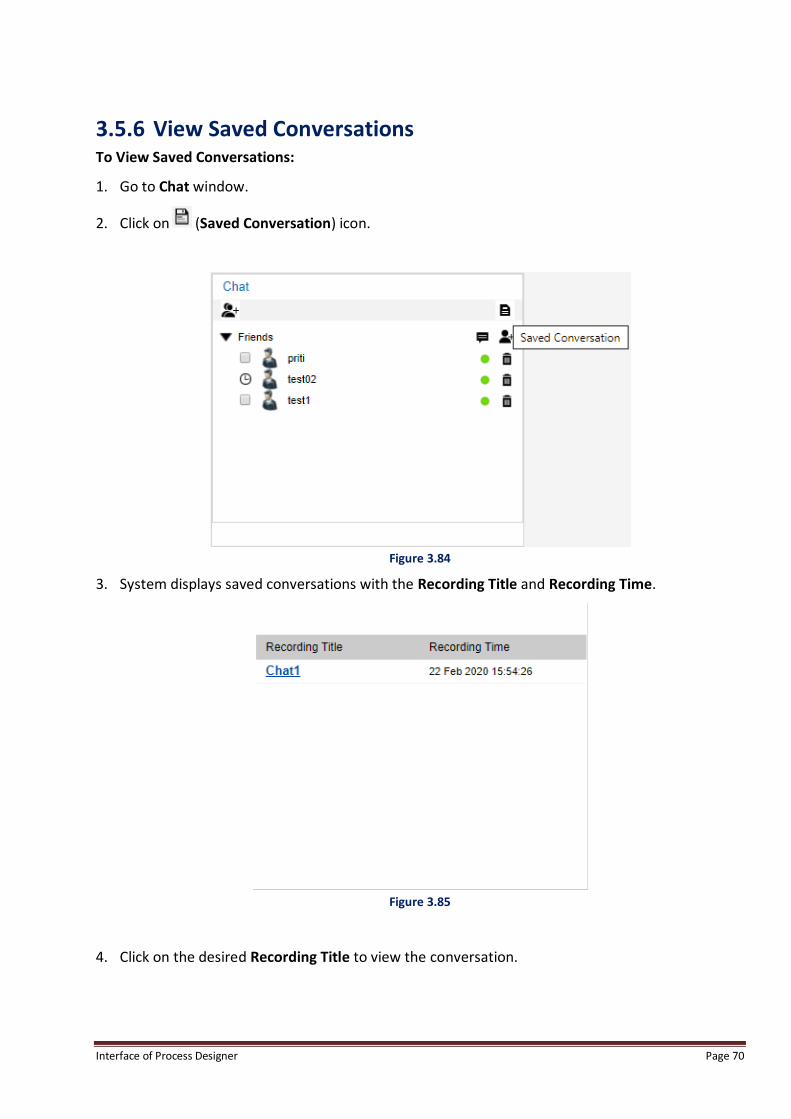
3.5.6 View Saved Conversations To View Saved Conversations:
1. Go to Chat window.
2. Click on (Saved Conversation) icon.
Figure 3.84
3. System displays saved conversations with the Recording Title and Recording Time.
Figure 3.85
4. Click on the desired Recording Title to view the conversation.
Interface of Process Designer Page 71
4 Create Project and Process A user needs to create a project and then create processes within a project.
4.1 Create Project
NOTE:
padmin (process designer administrator) user is able to access all Menu Options by default.
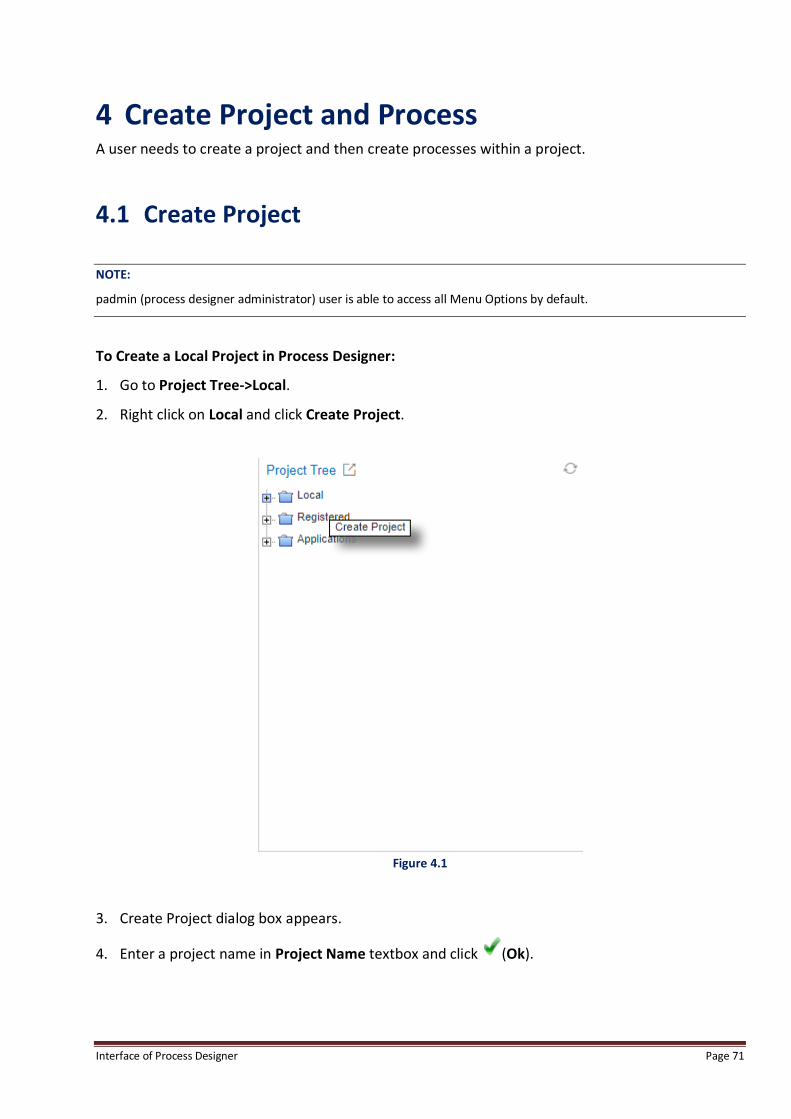
To Create a Local Project in Process Designer:
1. Go to Project Tree->Local.
2. Right click on Local and click Create Project.
Figure 4.1
3. Create Project dialog box appears.
4. Enter a project name in Project Name textbox and click (Ok).

Interface of Process Designer Page 72
Figure 4.2
5. Clicking on opens all the component of that project.
6. Once a Project is created, various processes of the same category can be added under that
particular project. The projects repository would be created under the local project. Once a
process is finalized, it is registered in the system.
7. The list of registered processes on the cabinet can be shown in Project Tree view parallel to
local projects repository. A Registered Process can be opened in read-only mode by clicking the
same in the project tree view. List of registered processes can be shown in Project tree view
under 'Registered' category. The hierarchy of the processes is maintained as for the Local
processes.
NOTE:
If a process does not have a parent project, it will be shown in default project.

Interface of Process Designer Page 73
4.2 Create Process To Create a New Process in a project:
1. Right click on Project Name and click on Create Process.
Figure 4.3
2. The Create Process dialog box opens up.
3. Select Process Type as Generic or Process Variant.
4. Enter Process Name to be created under a particular project.
Figure 4.4
5. Click (Ok) to create the new process in the project.

Interface of Process Designer Page 74
Figure 4.5
NOTE:
Whenever a process is transferred from one cabinet to another through OTMS (Omni Transport Management System),
system displays that transferred process under “default” project name (system generated default project).
Whenever a process is upgraded from lower iBPS version to iBPS, system displays that upgraded process under
“default” project name (system generated default project).

Interface of Process Designer Page 75
5 Design Process A new process can be designed in a project.
NOTE:
padmin user is able to access all Menu Options by default.
To design a process user can opt any of the two available views.
1. Abstract View
2. BPMN View
5.1 Views The Process can be designed in the Abstract and BPMN views:
5.1.1 Abstract View Abstract View is the simplest mode for designing the process, which can be used by a business
analyst or a naïve user to design the outlining of the process.
The designing panel is vertically divided into milestones, and all the activities linked to that
milestone are vertically arranged in that column.
It is just the abstract of the whole process where no conditions and linking are shown, and just a
blueprint of the process is shown.
Interface of Process Designer Page 76
Figure 5.1
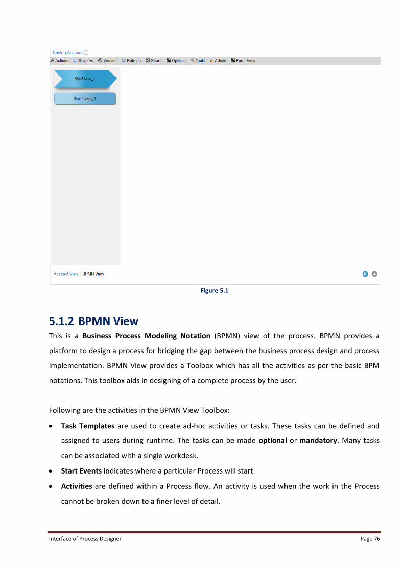
5.1.2 BPMN View This is a Business Process Modeling Notation (BPMN) view of the process. BPMN provides a
platform to design a process for bridging the gap between the business process design and process
implementation. BPMN View provides a Toolbox which has all the activities as per the basic BPM
notations. This toolbox aids in designing of a complete process by the user.
Following are the activities in the BPMN View Toolbox:
Task Templates are used to create ad-hoc activities or tasks. These tasks can be defined and
assigned to users during runtime. The tasks can be made optional or mandatory. Many tasks
can be associated with a single workdesk.
Start Events indicates where a particular Process will start.
Activities are defined within a Process flow. An activity is used when the work in the Process
cannot be broken down to a finer level of detail.

Interface of Process Designer Page 77
Intermediate Events are the intermediate steps between the start and end event. The process
cannot start or end at these steps.
Gateways are used to control how the Process flows through Sequence Flow as they converge
and diverge within a Process.
End Events indicate where a path of a Process will end.
Artifacts are used to provide additional information about the Process.
Swim Lanes is a graphical container for partitioning a set of activities from other activities.
Figure 5.2
5.2 Tool Box Tool Box in Process Designer provides a component palette for the application. It contains tools,
which are used to define a process.
NOTE:
The Toolbox is displayed on LHS of the Process Designer screen:

Interface of Process Designer Page 78
Figure 5.3
The features of these tools are as follows:-
1. These tools provide a means to design a business process with the variety of options provided in
it.
2. These tools are in the form of events and tasks for the process including gateways and artifacts,
which can be associated as the external interfaces with the process.
3. They are easy to use. The user just needs to click the item and dropping it onto the application
workspace area in order to draw a route.
The Tool Box is categorized into the following tabs:
Task Templates
Start Events
Activities
Intermediate Events
Gateways
End Events
Artifacts
Swim Lanes
BPMN supports five basic categories of elements:
1. Task Templates: The Task Templates are used to create ad-hoc activities within a process. A
task may or may not be dependent on another task within the process and can be executed any
time as and when required. This category has only one type of element:
New Task
2. Flow Objects: These are used to depict the overall flow in a business process. This category
consists of three core elements:
Events

Interface of Process Designer Page 79
Activities
Gateways
3. Connecting Objects: The Flow Objects are connected to each other with Connecting Objects.
There are two types of Connecting Objects:
Sequence Flow
Association
4. Swimlanes: A Swimlane is a visual mechanism of organizing different activities into categories of
the same functionality. A Lane represents a Participant in a Process. This category has only one
type of element:
Lane
5. Artifacts: These allow business analysts to bring some more information into the
model/diagram to make them more readable. The four types of elements are:
Text Annotation
Group Box
Data Object
Message
5.2.1 Task Templates The Task Templates are used to create ad-hoc activities within a process. A task may or may not be
dependent on another task within the process and can be executed any time as and when required.
Depending upon the requirement, a task can be made optional or mandatory.
This menu item enables inserting of a New Task.
NOTE:
User can click, drag and drop the components present under Task Templates tab in Task Lane.

Interface of Process Designer Page 80
Figure 5.4
By default, only New Task appears in the Task Templates. Other task templates appearing in the
Task Templates are global templates created during a task definition.
5.2.2 Start Events Start Event is the entry point of a work item in a business process. It specifies the introduction of
the work items in the process. This menu item enables inserting a Start Event work step in the
process. Start Events, consist of following components:-
Start Event
Conditional Start
Robotic Start
Robotic Start Block
NOTE:
User can click, drag and drop the components present under Start Events tab in SwimLane.
Interface of Process Designer Page 81
Figure 5.5
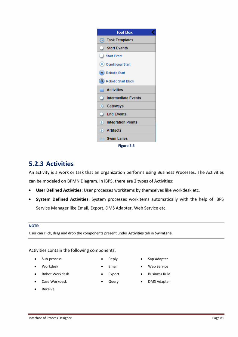
5.2.3 Activities An activity is a work or task that an organization performs using Business Processes. The Activities
can be modeled on BPMN Diagram. In iBPS, there are 2 types of Activities:
User Defined Activities: User processes workitems by themselves like workdesk etc.
System Defined Activities: System processes workitems automatically with the help of iBPS
Service Manager like Email, Export, DMS Adapter, Web Service etc.
NOTE:
User can click, drag and drop the components present under Activities tab in SwimLane.
Activities contain the following components:
Sub-process
Workdesk
Robot Workdesk
Case Workdesk
Receive
Reply
Export
Query
Sap Adapter
Web Service
Business Rule
DMS Adapter

Interface of Process Designer Page 82
Figure 5.6
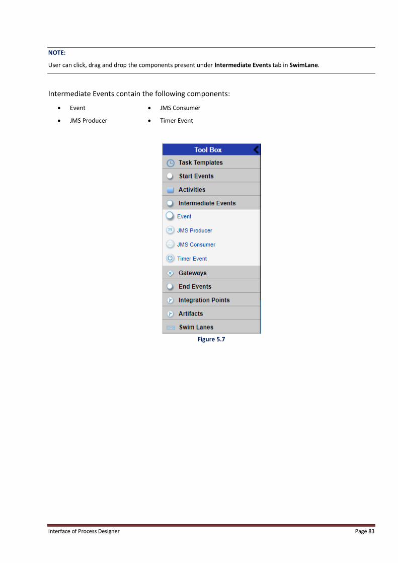
5.2.4 Intermediate Events Intermediate Event indicates when something happens (an Event) somewhere between the start
and end of a Process. It affects the flow of the Process, but will not start or (directly) terminate the
Process. Intermediate Events can be used to:
Show where Messages are expected or sent within the Process,
Show delays are expected within the Process,
Disrupt the normal flow through exception handling.
Show the extra work required for compensation.
Interface of Process Designer Page 83
NOTE:
User can click, drag and drop the components present under Intermediate Events tab in SwimLane.
Intermediate Events contain the following components:
Event
JMS Producer
JMS Consumer
Timer Event
Figure 5.7

Interface of Process Designer Page 84
5.2.5 Gateways Gateways are used to control how Sequence Flows interact as they converge and diverge within a
Process. If the flow does not need to be controlled, then a Gateway is not needed. The term
“Gateway” implies that there is a gating mechanism that either allows or disallows passage through
the Gateway- i.e., as Tokens arrive at a Gateway, they can be merged together on input and/or split
apart on output as the Gateway mechanisms are invoked.
There are menu items which enables inserting a Gateway in the process.
Gateways contain the following components:
Inclusive Distribute
Inclusive Collect
Parallel Distribute
Parallel Collect
Data Based Exclusive
NOTE:
User can click, drag and drop the components present under Gateways tab in SwimLane.
Figure 5.8
Interface of Process Designer Page 85
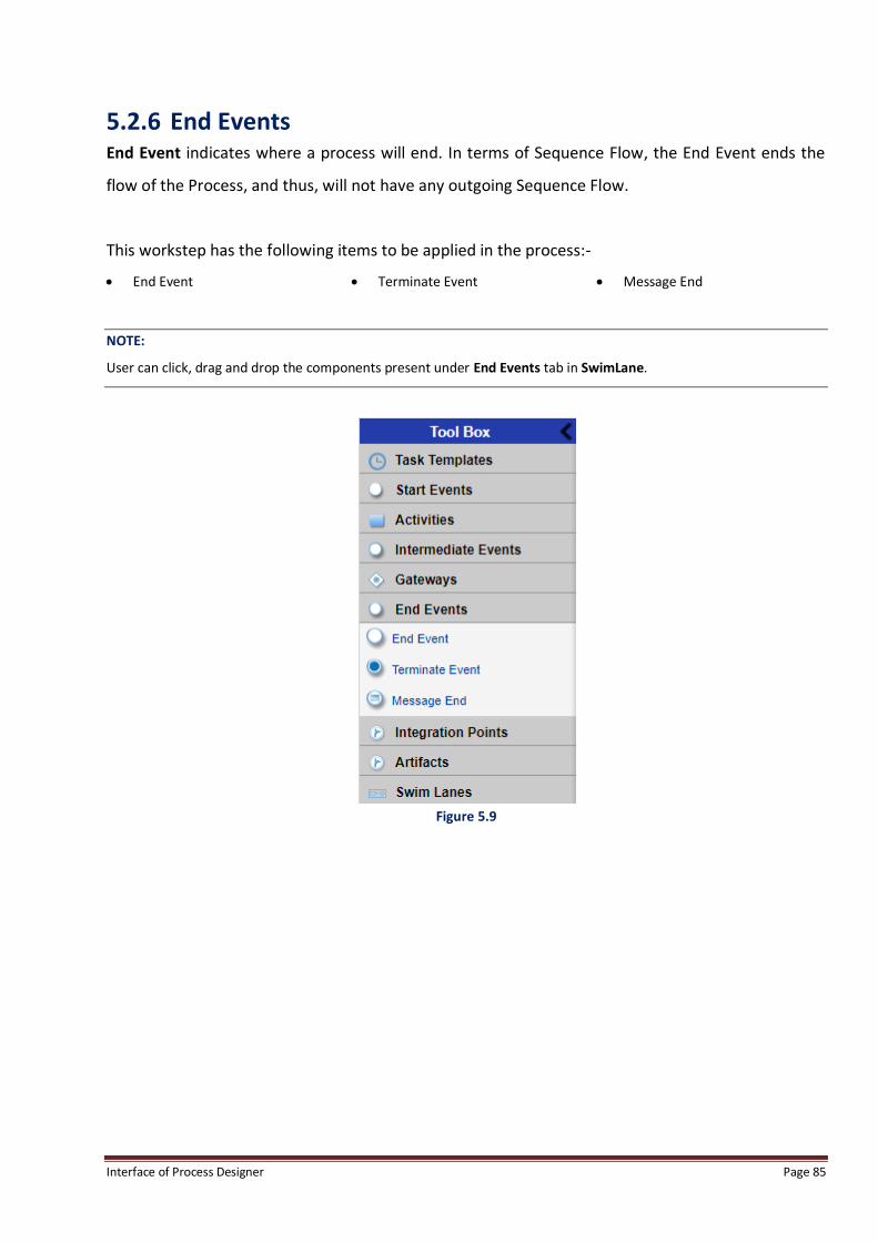
5.2.6 End Events End Event indicates where a process will end. In terms of Sequence Flow, the End Event ends the
flow of the Process, and thus, will not have any outgoing Sequence Flow.
This workstep has the following items to be applied in the process:-
End Event Terminate Event Message End
NOTE:
User can click, drag and drop the components present under End Events tab in SwimLane.
Figure 5.9

Interface of Process Designer Page 86
5.2.7 Artifacts An Artifact is a graphical object that provides supporting information about the Process or
elements within the Process. However, it does not directly affect the flow of the Process. BPMN has
standardized the shape of a Data Object. Other examples of Artifacts include critical success factors
and milestones. The components present in this tool are as follows:
Text Annotation Group Box Data Object Message
NOTE:
User can click, drag and drop the components present under Artifacts tab in SwimLane.
Figure 5.10
5.2.8 Swim Lanes Swim Lanes are visually separated rows within a process diagram. It groups different activities by
resource definitions, roles, classifiers, organization units, or locations. Swim Lanes are placed only
on the workspace when user clicks the Swim Lane icon on the Bubble bar.

Interface of Process Designer Page 87
NOTE:
User can left click on the components, drag them and then drop them anywhere in Swimlane, by releasing the
mouse click.
User can move the activity from one Milestone/Swim Lane to another using mouse only. Using keyboard,
movements done near borders will resize the Milestone/Swim Lane.
In case-type processes, a lane with name Task lane is added on top of all swimlanes. It can be resized but cannot be
deleted or moved like other swimlanes.
This lane can only contain tasks in a process. Activities cannot be added to this lane. Also, annotations are allowed
in this lane.
Figure 5.11
To design a new process, follow the given steps:
1. Click the BPMN notation icon in the Toolbox.
2. The cursor changes to the shape of the icon.
3. Click in the process design area.
4. This places the selected icon in the design area.
5. Similarly, click the desired icons in the Toolbox to design the process using BPMN notations.
Interface of Process Designer Page 88
6 Menu Bar Options Process Designer Menu Bar options are:
Actions
Save As
Version
Refresh
Share
Options
Tools
Admin
Form View
NOTE:
padmin user is able to access all Menu Options by default.
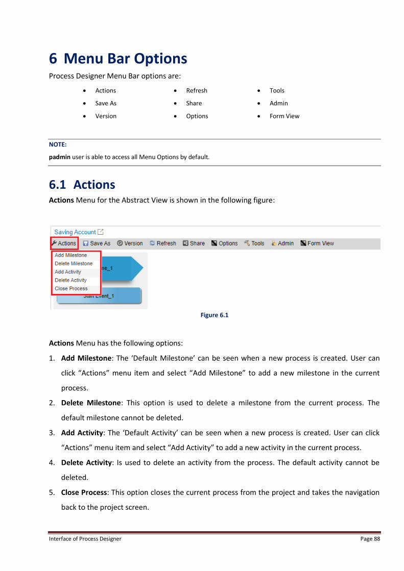
6.1 Actions Actions Menu for the Abstract View is shown in the following figure:
Figure 6.1
Actions Menu has the following options:
1. Add Milestone: The ‘Default Milestone’ can be seen when a new process is created. User can
click “Actions” menu item and select “Add Milestone” to add a new milestone in the current
process.
2. Delete Milestone: This option is used to delete a milestone from the current process. The
default milestone cannot be deleted.
3. Add Activity: The ‘Default Activity’ can be seen when a new process is created. User can click
“Actions” menu item and select “Add Activity” to add a new activity in the current process.
4. Delete Activity: Is used to delete an activity from the process. The default activity cannot be
deleted.
5. Close Process: This option closes the current process from the project and takes the navigation
back to the project screen.

Interface of Process Designer Page 89
6.2 Save As Save As menu is shown in the following figure:
Figure 6.2
Save Process has the following options:
1. Save as Same Version: This option simply saves the process. The changes are updated on the
same version of the process.
2. Save as Latest Version: Provides the user with the option of saving any version of the process as
the latest version. For instance, if there are versions 2.0 and 2.1 and we want to save a process
as 2.0, it will create a new copy of the same process with version 3.0.
3. Major Version: Adds +1.0 to the Version No.
4. Minor Version: Adds +0.1 to the Version No.
NOTE:
When in process view of BPMN View, press Ctrl+S keyboard keys to automatically save process as same version.
When in properties view of BPMN View, press Ctrl+S keyboard keys to automatically save the properties of the
process.

Interface of Process Designer Page 90
6.3 Version Version displays the version for the current process appended by the name of the user who has
created it.
Figure 6.3
6.4 Refresh Refresh is used to roll back to the last saved stage of the process.
6.5 Share This option is used to share the current process with all the users on a particular server. Every user
is able to view a particular process created by a particular process.
Refer to Collaborative Process Designing to learn how to share a process.

Interface of Process Designer Page 91
6.6 Options Options Menu is shown in the following figure:
Figure 6.4
The Options Menu has the following options:
Constants: Helps the user to define the constants related to a particular process. Constants are
used for processing rules. They are used to keep a value fixed throughout a process. A prefix
CONST_ is added to the name. The value will always be stored as string.
Define Tables: Enables the user to define tables, which can be used in mapping complex and
Array data types.
External Variables: Enables the user to define variables for the process.
Complex Types: Enables user to enter user-defined data types.
Queue Variables: Queue variables (user defined variables) are process variables used mainly for
defining rules and actions at different worksteps. Queue variables are defined from within the
process. The user can define a maximum of 26 queue variables. This menu item invokes the
Variable Definition dialog box for defining queue (user-defined) variables.
Search Variables: This option enables the user to configure the search criteria on variables
defined for the process.
Define Variable Alias: Enables the user to define alias for the already defined variables when the
registered process is opened in the read-only mode.
Export/Import Data: This option enables the user to export/import fragment and variables.

Interface of Process Designer Page 92
6.6.1 Constants To Define a Constant:
1. Click Options menu, and then click Constants.
2. Constant Definition window is invoked.
Figure 6.5
3. Enter the Name for the constant.
4. Enter the Default Value, if required.
5. Click on Add to add the Constant.
6. Click OK to save the defined constant, else click Cancel.
To Modify the Constant:
1. In the Constant Definition screen, select the constant whose default value is to be modified.
User can only modify the Default Value.
2. Change the Default Value.
3. Click OK to save the changes.
To Delete a Constant:
1. Select the radio button of the desired constant in the Define Constants screen.
2. Click Delete.
3. Save Process message box appears.
4. Click Yes to save the process and confirm constant deletion.

Interface of Process Designer Page 93
6.6.2 Define Tables To Create a New Table:
1. Click Options-> Define Tables.
2. Click New , appearing in front of Define Tables textbox.
3. The Define Table text box becomes editable.
4. Add new table name.
5. To Add a New field, carry the following steps:
a. Enter the Field Definition Name.
b. Select the Type from the drop down box.
Figure 6.6
c. Click Add. The Field gets added to the table.

Interface of Process Designer Page 94
Figure 6.7
d. Click on Ok to save table definition.
e. In case the user selects Cancel, the said field would not get added to the table.
To Add Multiple Fields:
1. Click on Multiple Fields link.

Interface of Process Designer Page 95
Figure 6.8
2. Create Table screen appears as shown.
NOTE:
Multiple Fields option is available only when creating a new table. This option allows user to create multiple field
definitions of a table in one go.
3. Click on Add Column.
4. The display area of the screen changes as shown.

Interface of Process Designer Page 96
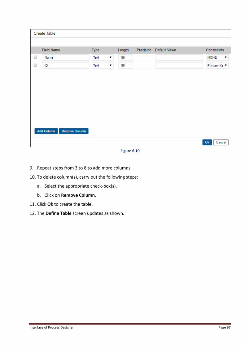
Figure 6.9
5. Enter Field Name.
6. Select data type from Type drop down list. Length field is updated as per the selected data
type.
7. Enter Default Value if required.
8. Select Constraints (None, Primary Key and Unique Key).
Interface of Process Designer Page 97
Figure 6.10
9. Repeat steps from 3 to 8 to add more columns.
10. To delete column(s), carry out the following steps:
a. Select the appropriate check-box(s).
b. Click on Remove Column.
11. Click Ok to create the table.
12. The Define Table screen updates as shown.

Interface of Process Designer Page 98
Figure 6.11
To Add to existing Table
1. Select the required table from Select Item drop down menu.
Figure 6.12

Interface of Process Designer Page 99
2. Click on Mapping button.
3. All the fields of the selected table are displayed.
Figure 6.13
4. To add more fields:
Enter Field Name.
Select data type from the Type drop down. Length will be updated as per the selected data
type.
Enter Default Value if required.
Select Constraints (None, Primary Key and Unique Key).
Click on Add button.
The Field gets added to the table.
To Modify Existing Data field:
1. Select the field.
2. Make the required changes.
3. Click Modify to save the changes made.

Interface of Process Designer Page 100
To Delete Existing Field:
1. Select the Field from the available list of fields.
2. Click Delete.
In the Field Definition dialog box, user may enter the following:
Field Name: Specifies the name of the field (column) in the local table. No two fields of the
local table can have the same name.
Type: Specifies the type of the field. i.e. Text, Float, Integer, Long, Date, Boolean, ShortDate,
Time, Duration, NText from the drop-down menu.
Length: Specifies the length of the field. This is enabled only in case when the field type is
Text. Maximum length can be specified as 255. For other field types, default values of length
are taken.
Default Value: Specifies the default value for the field.
Constraints: Select the checkbox if user wants to apply constraints.
Primary Key: Sets the field as primary key, if this check box is selected.
Unique Key: Sets the field as unique key, if this check box is selected.
NOTE:
1. If a user checked out as registered process, following changes are not permissible:
Existing columns cannot be deleted.
Data types of existing columns cannot be modified.
Primary/Unique Key constraints cannot be altered.
Data types can be modified and columns can be deleted from backend. In such cases, the user needs to re-map
the table from External Variables window.
2. User is only allowed to change default value and add new columns in existing tables in check out process.
3. If user defines external mapping for table, it is mandatory for the table to have two fields:
“itemindex” of type text
“itemtype” of type text.
Otherwise system does not allow user to define external mapping for that particular table.
4. For mapping itemindex and itemtype with ExternalVariable, both of them should be selected as Primary Type
during Define Table.
5. If user defines table for array type queue variable, system displays only those tables which have column
“Insertionorderid” of type integer or long defined in it.

Interface of Process Designer Page 101
6. If a user defines table for complex type queue variable and intend to use an array of complex structure, it’s
mandatory to create a column “Insertionorderid” of type long. User should also create a text field for storing
mapped ProcessInstanceId of type text with minimum 50 character length in a table, which will get mapped to a
complex structure.
7. If user works with Arabic (Other than English) locale, he is allowed to define table name and column name in Arabic
locale. But he is not allowed to define mandatory columns like itemindex, itemtype and insertionorderid in Arabic
locale.
8. If the user has added/deleted/modified/ columns of a table from backend, then only he is required to re-map that
table in External Variables screen.
6.6.3 External Variables To Define the Online Work Item Data:
1. Click Options Menu and then click External Variables.
2. External Variables dialog box appears.
Figure 6.14
3. Select the External Data Table, which has to be updated.
4. Click on Map Data. The record data rows get activated.
5. Depending on the table selected, the fields for that table are to be mapped with Record Data.
6. Click Ok to define the variable data.
7. Else, click Cancel. After the data definition, these variables will be available at all work steps.

Interface of Process Designer Page 102
NOTE:
Tables having constraints like primary key/unique key cannot be mapped as External table.
External Variables should be defined in English Language only. If they are defined in Non English language and their
access rights are provided on Start Event, Event, Receive and Reply worksteps, system will not execute associated web
service.
6.6.4 Complex Types To Define a Complex Data Type:
1. Select Options-> Define Complex Types.
2. Complex Type Definition dialog box appears, as shown in the following figure.
Figure 6.15
3. Click the New button next to the Structure Name text box.
4. The Structure Name text box is enabled.
5. In the Structure Name text box, type the name of the structure.
6. From the Extension of drop-down list, select a value.
7. Extension of displays all the defined structures from which the new structure can inherit.
8. Click the New button next to the Member Name text box.
9. The Member Name text box is enabled.

Interface of Process Designer Page 103
10. In the Member Name text box, type the name of the member field of the structure.
11. From the Member Type drop-down list, select the type of the member.
Figure 6.16
12. Member Type contains the supported data types as well as user-defined structures.
13. Click Add to add the complex type.
14. Similarly, user can add more structures. After the structures are added, they are displayed in
the tree view in the left pane, as shown in the following figure:

Interface of Process Designer Page 104
Figure 6.17
NOTE:
When user selects a structure or member in the left pane, its details are displayed in the right pane. User can define the
structure member as an Array type by selecting the Array check box.
To Delete Complex Type:
1. Select Structure Name.
2. Click on Delete button.

Interface of Process Designer Page 105
Figure 6.18
3. Click on Ok to save.
NOTE:
Complex Variables should be defined in English Language only. If they are defined in Non English language and their
access rights are provided on Start Event, Event, Receive and Reply worksteps, system will not execute associated web
service. Complexes can be created in hierarchical way, where a complex can be created as a part of another complex.
Complex Structure Hierarchy:
Complex structure hierarchy can be created as shown below:

Interface of Process Designer Page 106
Figure 6.19
6.6.5 Queue Variables To Create a Queue Variable for Normal Data Type:
1. Click the Options menu, and then click Queue Variables.
2. The Variable Definition dialog box appears, as shown in the following figure.
Figure 6.20

Interface of Process Designer Page 107
3. By default, the User Defined Variables option is selected.
4. Here, the user can define variables.
5. Enter Name.
6. Select the Type of the variable. Following are the types of variables available:-
a. Integer
b. Long
c. Float
d. Date
e. Text
f. Complex (Complex types are user-defined data types.)
NOTE:
In case, Float Type is selected then following screen appears. In this screen Precision text box appears. Provide the
integer value in the available text box. This integer is the level till which Precision is required. For example, if the
Precision is 2, then after decimal two level of numerical value will be provided.
7. User has the option to enter the Default Value for the variable. Select the Default Value check
box, and then enter the Default Value in the provided checkbox. Default value set for a Text
Queue variable is shown below:

Interface of Process Designer Page 108
Figure 6.21
8. After defining the Default Value for the variable, if there is no value specified for that variable
while processing in the route, the default value appears in the Client Desktop and Web Process
Client.
9. Select the System Variable name that has to be mapped with the new Queue Variable, from
the Mapped Variable selection list. Based on their type, varied amount of System Variables are
available, which are as follows:-
a. Integer : 8
b. Long : 6
c. Float : 2
d. Date : 6
e. Text : 20
10. Click Add.
11. The variable gets added in the list view on the left side, as shown:

Interface of Process Designer Page 109
Figure 6.22
12. Click on Ok to save the changes made; else click Cancel to cancel the operation.
To create a variable for Complex Type:
1. Click the Options menu, and click Queue Variables.
2. The Variable Definition dialog box appears, as shown in the following figure:
Figure 6.23
3. Enter the Name of the complex variable.
4. Select Complex Type from type dropdown.

Interface of Process Designer Page 110
Figure 6.24
5. Click Add.
6. The variable gets added in the list view on the left side, as shown:
Figure 6.25
7. Click Ok to save the changes made.
8. Else click Cancel to cancel the operation.

Interface of Process Designer Page 111
To Define Rule for Complex Variable:
Complex Loading Rules can be defined for Queue variables for complex structures. The objective is
that in cases, where rule condition evaluates to false, then the complex will not be loaded. The
purpose of this rule definition is to reduce the performance impact of bringing data for multiple
complex structures. This rule definition will enable conditional loading of data in complex
structures, during the call executed to fetch the work-item data on first time opening of work-item
and form loading. If a particular form section is expanded, then the complex loading rules are not
considered and the data in all the complexes in that section will be shown to the user.
1. Select Complex Variable from the Queue Variables list in the left panel.
Figure 6.26
2. Click on Define Rule button.
3. System displays following Rule Definition Screen:

Interface of Process Designer Page 112
Figure 6.27
4. Define Rule Condition, using If operator and any process variable and value.
5. Click on Add button.
6. Select Complex Variable.
7. Click on Add button.
8. Click on Ok button.
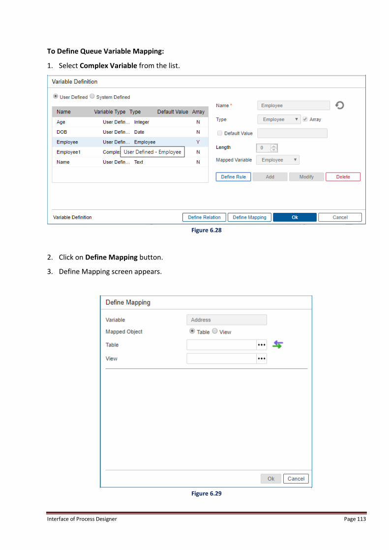
Interface of Process Designer Page 113
To Define Queue Variable Mapping:
1. Select Complex Variable from the list.
Figure 6.28
2. Click on Define Mapping button.
3. Define Mapping screen appears.
Figure 6.29

Interface of Process Designer Page 114
4. Click on to select Table for mapping. Define a table to be mapped with Complex table with
these parameters as shown below:
S No. Field Name Field Type Comments
1. Insertionorderid Long It must be named exactly same as
“insertionorderid”. Required to create an array of
complexes to be mapped with ListView.
2. mapper Text(50) This field can be given any name with minimum
length as 50.
3. Other fields (Any name can be
given)
Can be of any type These fields are basically used to store the data
which will be entered by the user.
5. Select the required table from the list.
Figure 6.30
6. Click on (Define Mapping) button.
7. Select Table Columns from the dropdown that appears after selecting Define Mapping.
8. Click on Ok button.
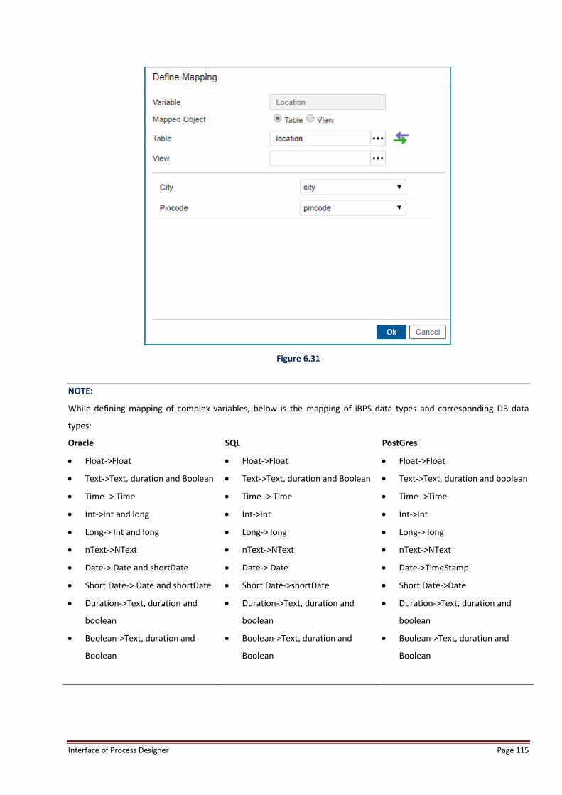
Interface of Process Designer Page 115
Figure 6.31
NOTE:
While defining mapping of complex variables, below is the mapping of iBPS data types and corresponding DB data
types:
Oracle SQL PostGres
Float->Float
Text->Text, duration and Boolean
Time -> Time
Int->Int and long
Long-> Int and long
nText->NText
Date-> Date and shortDate
Short Date-> Date and shortDate
Duration->Text, duration and
boolean
Boolean->Text, duration and
Boolean
Float->Float
Text->Text, duration and Boolean
Time -> Time
Int->Int
Long-> long
nText->NText
Date-> Date
Short Date->shortDate
Duration->Text, duration and
boolean
Boolean->Text, duration and
Boolean
Float->Float
Text->Text, duration and boolean
Time ->Time
Int->Int
Long-> long
nText->NText
Date->TimeStamp
Short Date->Date
Duration->Text, duration and
boolean
Boolean->Text, duration and
Boolean

Interface of Process Designer Page 116
To Define Relation:
1. Select Complex Variable from the list.
Figure 6.32
2. Define Mapping for the variable from the link (Refer Define Mapping), which is a prerequisite to
Define Relation.
3. Click on Define Relation button.
4. System displays following screen:
Figure 6.33

Interface of Process Designer Page 117
5. Click on (New) icon.
6. Click on (New) icon. System enables the Parent Table Field and Child Table Field.
Figure 6.34
7. Select Parent Table Field from the dropdown. In case selected table is WFInstrumentTable,
then the Parent Table Field to be selected should be ProcessInstanceId.
8. Select Child Table Field from the dropdown. This should be a mapping field created in the table
created for Complex with type text and minimum length 50.
9. Click on Add button.
10. System displays following screen:
Figure 6.35

Interface of Process Designer Page 118
11. Click on Ok button.
NOTE:
Relation definition should be done between the ProcessInstanceId of the WFInstrumentTable and a field of type
text in the table mapped to complex. The objective of this relation is to store ProcessInstanceId of a work-item in a
mapped field in complex table, so that the data corresponding to the work-item id can be picked up from the
corresponding complex table row, and fetched, where required. If External Table has been created in a process,
then the external table can also be mapped to a complex table.
Select Array option and use insertionorderid in the complex table to enable mapping of complex to the ListView in
the form.
While defining relation, user must define relation with one to one mapping i.e. Same child table field should not be
mapped to two different parent table fields.
Same parent table field should not be mapped with two different child table fields.
Modify Queue Variable:
1. To modify the Queue variable, select that variable and click Modify.
2. Its corresponding Name, Type and Default Value are displayed in the Name, Type, and Default
value controls respectively. User can only change the default value.
Delete Queue Variable:
1. Select the variable.
2. Click Delete to delete the variable.
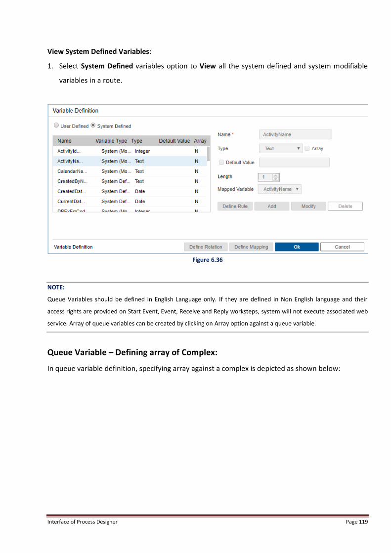
Interface of Process Designer Page 119
View System Defined Variables:
1. Select System Defined variables option to View all the system defined and system modifiable
variables in a route.
Figure 6.36
NOTE:
Queue Variables should be defined in English Language only. If they are defined in Non English language and their
access rights are provided on Start Event, Event, Receive and Reply worksteps, system will not execute associated web
service. Array of queue variables can be created by clicking on Array option against a queue variable.
Queue Variable – Defining array of Complex:
In queue variable definition, specifying array against a complex is depicted as shown below:

Interface of Process Designer Page 120
Figure 6.37
6.6.6 Search Variables Search variables are the Selected Queue Variables that can be used for searching the work-items
during process execution. Variables should also be specified in Search Results which will be visible
in output on carrying out any search using Search Variables. These Search Variables will be visible to
serve as default search option in Advanced Search Bar. All users for a process will be able to use
these search variables and search results options from the Advanced Search bar.
NOTE:
Within the definition of Search Variables, Set Filter option shown below enables searching on the basis of Search
variables by applying an additional filter to search. For instance, in the queue variables below, a search variable can be
applied to “Student Name = Neha”. The corresponding results would be displayed accordingly.

Interface of Process Designer Page 121
Figure 6.38
The Search Variables definition with filter definition is as shown below:
Figure 6.39

Interface of Process Designer Page 122
The Search Results definition of variables is as shown below:
Figure 6.40
Only 10 Search Variables can be selected, if user tries to select more than 10 Search Variables, user
will see a message as shown below:
Figure 6.41

Interface of Process Designer Page 123
The Search Variables selected will be visible in Advanced Search option as business variables after
selecting that specific process as shown below:
Figure 6.42

Interface of Process Designer Page 124
6.6.7 Export/Import Data
Export/Import Data Option provides the option of Exporting/Importing NGForm form fragments
and Queue Variables. User can click on Export/Import Data option from Menu tab Options as
shown below:
Figure 6.43
Once user clicks on Menu option – Export/Import Data, user will see the option to Export/Import
fragments as shown below:

Interface of Process Designer Page 125
Export/Import Fragment
Figure 6.44
User can select the fragment to be downloaded and click on button Ok to download the form
fragment. Once user clicks on Ok, user will see the message, that fragment is getting downloaded
as shown below:

Interface of Process Designer Page 126
Figure 6.45
Once the form fragment download is complete, user will see the downloaded zip file as shown
below:
Figure 6.46
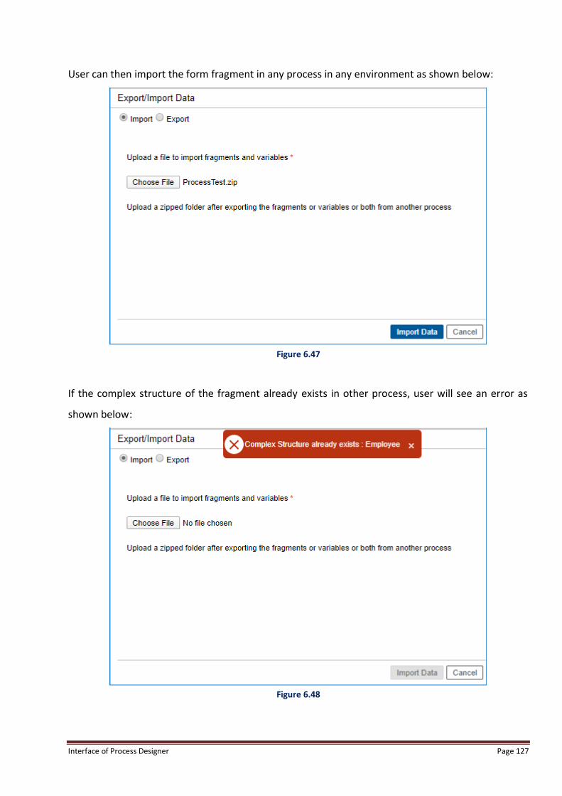
Interface of Process Designer Page 127
User can then import the form fragment in any process in any environment as shown below:
Figure 6.47
If the complex structure of the fragment already exists in other process, user will see an error as
shown below:
Figure 6.48
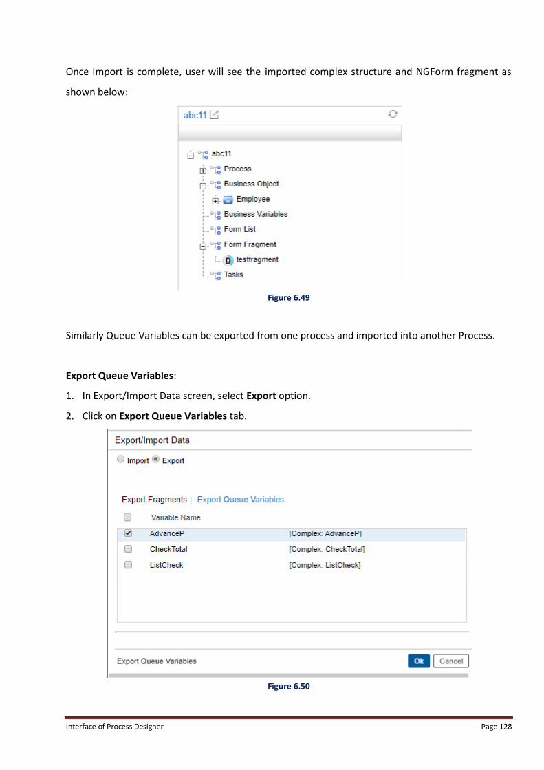
Interface of Process Designer Page 128
Once Import is complete, user will see the imported complex structure and NGForm fragment as
shown below:
Figure 6.49
Similarly Queue Variables can be exported from one process and imported into another Process.
Export Queue Variables:
1. In Export/Import Data screen, select Export option.
2. Click on Export Queue Variables tab.
Figure 6.50

Interface of Process Designer Page 129
3. Select the required variables and click on Ok to download.
4. The following message appears.
Figure 6.51
5. Once the selected variable download is complete, extract the zip file to see the variables.
Figure 6.52

Interface of Process Designer Page 130
Export Queue Variables:
1. The exported (downloaded) Queue Variables can be imported in any process in any
environment.
2. In Export/Import Data screen, select Import option.
3. Click on Import option.
4. Click on Choose File and select the zip file to be imported.
5. Click on Import Data.
Figure 6.53
6. If the selected queue variable already exists in other process, an error message is shown.

Interface of Process Designer Page 131
Figure 6.54
7. Once Import is complete, the imported queue variables are shown in the process tree.
Figure 6.55

Interface of Process Designer Page 132
6.6.8 Define Variable Alias Define Variable Alias is the means to assign an alternate name to specific variables in the process.
Alternate names can only be defined in a Registered Process and not a Local Process. Once a
variable alias is defined, the variable is renamed in the entire process and the new name is used.
NOTE:
1. User is allowed to define “Alias” for the already defined variables, when the registered process is opened.
2. Define Variable Alias menu item is enabled when the registered process is opened in the read-only mode.
On clicking Define Variable Alias, the following screen is displayed containing the name of all the
defined Queue variables and defined External Table Variables. Complex and Array type variables
are not displayed.
Define Variable Alias Menu option can be seen in Process Modeler, for a registered process, under
Options as shown below:
Figure 6.56
Once user clicks on this option, user will be able to see the below pop-up screen, in which variable
aliases can be defined.
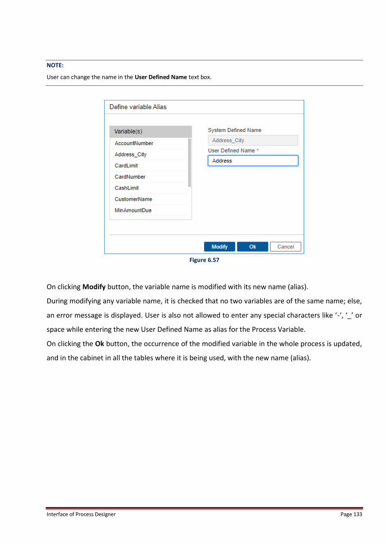
Interface of Process Designer Page 133
NOTE:
User can change the name in the User Defined Name text box.
Figure 6.57
On clicking Modify button, the variable name is modified with its new name (alias).
During modifying any variable name, it is checked that no two variables are of the same name; else,
an error message is displayed. User is also not allowed to enter any special characters like ‘-‘, ‘_’ or
space while entering the new User Defined Name as alias for the Process Variable.
On clicking the Ok button, the occurrence of the modified variable in the whole process is updated,
and in the cabinet in all the tables where it is being used, with the new name (alias).
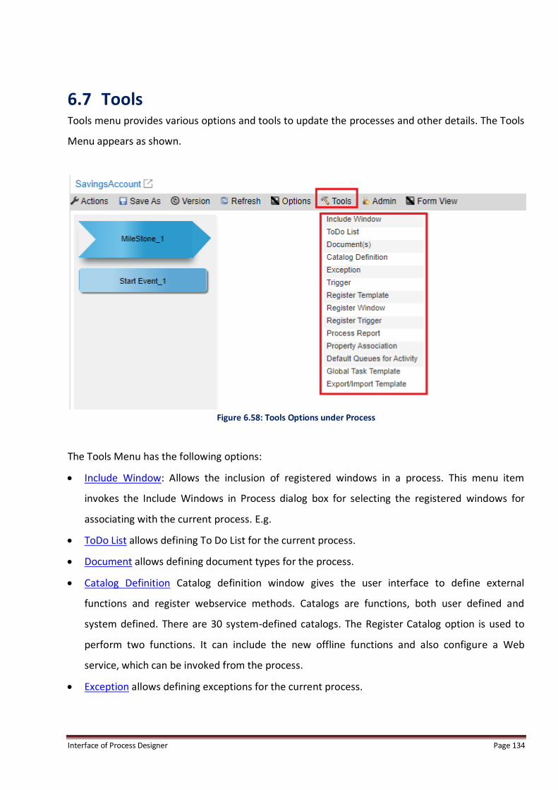
Interface of Process Designer Page 134
6.7 Tools Tools menu provides various options and tools to update the processes and other details. The Tools
Menu appears as shown.
Figure 6.58: Tools Options under Process
The Tools Menu has the following options:
Include Window: Allows the inclusion of registered windows in a process. This menu item
invokes the Include Windows in Process dialog box for selecting the registered windows for
associating with the current process. E.g.
ToDo List allows defining To Do List for the current process.
Document allows defining document types for the process.
Catalog Definition Catalog definition window gives the user interface to define external
functions and register webservice methods. Catalogs are functions, both user defined and
system defined. There are 30 system-defined catalogs. The Register Catalog option is used to
perform two functions. It can include the new offline functions and also configure a Web
service, which can be invoked from the process.
Exception allows defining exceptions for the current process.

Interface of Process Designer Page 135
Trigger: Triggers are the events that perform some specific task. These tasks includes sending a
mail, setting the value for data variables, invoking an application, invoking data form for data
entry, and communicating from external systems for data updating and retrieval. There are
seven standard types of triggers, such as, Mail trigger, Launch Application trigger, Execute
trigger, Data Entry trigger, Set trigger, Generate response trigger and Exception trigger.
Register Template allows a user to add a word template in the process for a defined document
type.
Register Window: Register Window menu item invokes the Register Window dialog box for
registering new property windows with the current process.
Register Trigger: Registers a user defined (custom) trigger type in the process. Users can define
a new trigger types (Custom Trigger Type). This menu item invokes the Trigger Definition dialog
box for defining triggers for the current process. These are used to define the events at the
defined worksteps in a process. These events can invoke Triggers that can send messages or
invoke exception-processing programs. Triggers can be used by the system for sending
mails/fax, generating responses, invoking data form for data entry, communicating from
external systems for data updating and retrieval, informing supervisors of exceptional
conditions etc. Besides opening the Trigger definition window from the Triggers option under
Options menu, the user can also define them directly by clicking the required trigger type from
the Tool Box. After registering a Custom Trigger Type, triggers of this defined type can be
defined in the process. This menu item invokes the Custom Trigger Type Definition Interface.
Process Report: Displays a detailed report of all the worksteps in the process. Process Report
can be saved in any of the three formats – Doc, PDF & HTML.
Property Association: Profile Association is a link under the tools; it is used to launch the
multiple activity association screens.
Default Queues for Activity: Automatically creates separate queue for all activities if the
checkbox against Default Queues for Activity is selected.
If user deselects checkbox against Default Queues for Activity for a particular swimlane, he has
to manually create separate queue for all activities except reply and workdesk.
If user selects checkbox against “Default Queues for Activity” for a particular swimlane, system
will automatically create separate queue for all activities present in selected swimlane.

Interface of Process Designer Page 136
Register SAP Details: Allow user to associate multiple SAP servers configuration with processes
through which process would integrate with SAP servers. SAP details registration is specific to
process.
Register BRT Details (For Registered Process): Allows a user to create new URL for Business Rule
Task (BRT) configuration details to access the data on new configured URL. If user wants to
access data from any other place except his source location, then he can easily access the data
through Register BRT Details.
Global Template: When defining a new task, user can save them as global template. Once
saved, it is made available across the cabinet.
6.7.1 Include Window The newly created window has to be included in the process for viewing it while defining the
workstep properties.
To Include Property Windows in the Current Process:
1. Click Tools menu.
2. Click Include Window. Include Window in Process dialog box is invoked.
Figure 6.59
3. Select the required window to be included in the process.
4. Click Ok to save the changes made, else click Cancel.

Interface of Process Designer Page 137
NOTE:
By default, all the standard Work desk windows are included in a process. But for any new window registered, user will
have to include in through this option. E.g. if Task pane is required for case management processes, then Dynamic Case
needs to be selected. If this selection is removed, Task Pane will not be seen in Process Window.
6.7.2 ToDo List To Define To Do List:
1. Click Tools menu and then click ToDo List.
2. To-Do List Definition dialog box is invoked.
Figure 6.60
3. Enter To Do Item name and Description.
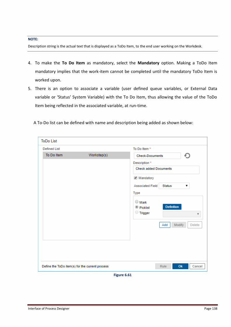
Interface of Process Designer Page 138
NOTE:
Description string is the actual text that is displayed as a ToDo Item, to the end user working on the Workdesk.
4. To make the To Do Item as mandatory, select the Mandatory option. Making a ToDo Item
mandatory implies that the work-item cannot be completed until the mandatory ToDo Item is
worked upon.
5. There is an option to associate a variable (user defined queue variables, or External Data
variable or ‘Status’ System Variable) with the To Do Item, thus allowing the value of the ToDo
Item being reflected in the associated variable, at run-time.
A To-Do list can be defined with name and description being added as shown below:
Figure 6.61

Interface of Process Designer Page 139
Once user clicks on add, the To Do item being added will be reflected in left panel under Defined
List as shown below:
Figure 6.62
NOTE:
To Do List Interface can also be invoked from the Property Sheet of a WorkDesk step. In this case all text type variables
that have been granted access permissions on that workstep will be available in the variable selection list.
6. The To Do list can be defined as Mark, Picklist or Trigger type.
a. Mark type ToDo Items appear as description strings followed by a selection box containing
“Yes”, “No”, “N/A” and <blank> selection items. End User can select any of these options as
the value of the ToDo Item.
b. Trigger type ToDo Items appear as description strings followed by a text box and a button.
End User can click on the button to invoke the associated Trigger, and the result of the
trigger in terms of Success or Failure becomes the value of the ToDo Item.

Interface of Process Designer Page 140
c. PickList type ToDo Items appear as description strings followed by a selection box
containing the pick list defined by the designer. End User can select any one of the pick list
option as the value of the ToDo Item.
Picklist type of To Do list is defined in the following steps:
1. Select Picklist option button and click Definition. Picklist Definition dialog box is invoked.
Figure 6.63
2. Define Picklist Value and click Add to add them.
3. To remove the picklist value, select it and click Delete.
4. Click Ok to save the changes, else click Cancel.
5. Click Add to add the To Do list for the Process.

Interface of Process Designer Page 141
Figure 6.64
6. Click Ok to save the To Do list, else click Cancel.

Interface of Process Designer Page 142
6.7.3 Documents To Define Document Type:
1. Click Tools menu and then click Document.
2. Document Types definition dialog box appears.
Figure 6.65
3. Enter the Document Type.
4. Click Add to add the document type.
5. The document type is added in the Available Document Type(s) list.
6. Click Delete to remove the selected document type from the Available Document Type(s) list.
7. Interface Rule with button called Rule is provided which on getting clicked launches a pop-UI
with rule definition for fetching all documents in the Document List made visible to the user at
once on clicking of a work-item. If the rule evaluates to a false, document won’t be shown in the
document list to the user. The document showing rules for Document List can be defined in the
pop-up UI as shown below:
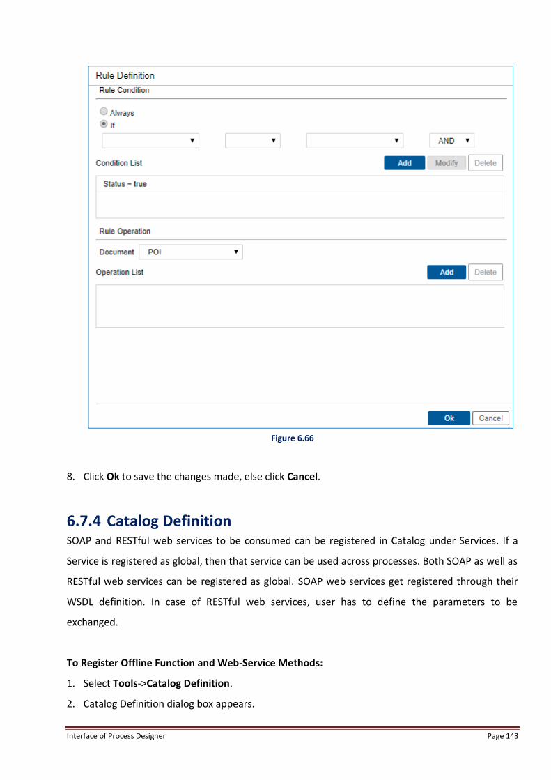
Interface of Process Designer Page 143
Figure 6.66
8. Click Ok to save the changes made, else click Cancel.
6.7.4 Catalog Definition SOAP and RESTful web services to be consumed can be registered in Catalog under Services. If a
Service is registered as global, then that service can be used across processes. Both SOAP as well as
RESTful web services can be registered as global. SOAP web services get registered through their
WSDL definition. In case of RESTful web services, user has to define the parameters to be
exchanged.
To Register Offline Function and Web-Service Methods:
1. Select Tools->Catalog Definition.
2. Catalog Definition dialog box appears.

Interface of Process Designer Page 144
3. Click on SOAP, as by default you will see two options of SOAP and RESTful. SAP will also appear
in catalog, if SAP has been enabled for this Process Modeler instance.
Figure 6.67
4. This interface has three tabs, WebService, Catalog and SAP.
NOTE:
It is not possible to use webservices containing <s:any/> tag in catalog definition.
To Configure and Register a New Web service:
1. Select the WebService tab:
2. The webservice tab is used to manage webservices for the process. User can register, modify
and un-register a webservice method from this window.
3. User should first select SOAP web service type.

Interface of Process Designer Page 145
4. User can select Global, if user wants to use this web service across processes. Once global is
selected, this web service will be registered globally and will be available across processes.
5. In case SOAP has been selected, the Web Service tab has option naming “WSDLLocation”
through which the required web service can be registered in the process:
6. WSDLLocation: User can directly enter the URL location of the WSDL corresponding to the
required web service.
To Register a Web Service Using the WSDL Path:
1. Click New button. The textbox and the Go button get enabled.
2. Enter the URL of the Web service in the Specify WSDL Location textbox.
Figure 6.68

Interface of Process Designer Page 146
3. The WSDL file for the web service is parsed at the server end automatically by entering the
server path in Specify WSDL Location text box. Location of the WSDL file can be any URL or any
absolute path, which should be present on the server.
a. If connection to web server hosting web services is to be accessed through a Proxy server,
then to define network details and credentials, login to OFservices (iBPS Service Manager).
b. Select the connected network on which user wish to register a Web Service.
Figure 6.69
c. Click Manage button. The following screen appears:
Figure 6.70
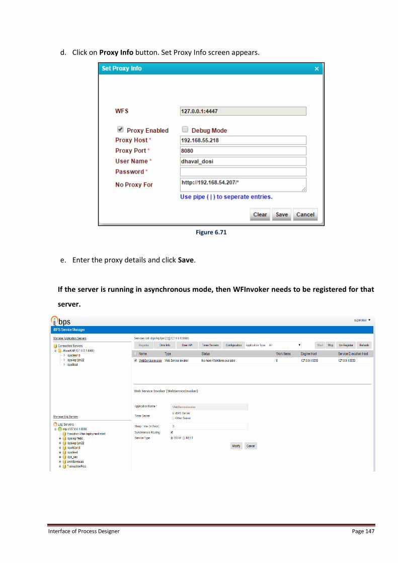
Interface of Process Designer Page 147
d. Click on Proxy Info button. Set Proxy Info screen appears.
Figure 6.71
e. Enter the proxy details and click Save.
If the server is running in asynchronous mode, then WFInvoker needs to be registered for that
server.

Interface of Process Designer Page 148
4. Return to Catalog Definition screen
5. Click Go button to retrieve the web service name and methods exposed by the specified web
service in the Service Name and Method Name selection lists.
6. Select the required Service Name and Method Name from the respective selection lists.
Figure 6.72
7. Click Register button to register the specified Web service. The registered Web services are
displayed in the Webservice pane, as shown in the following figure.

Interface of Process Designer Page 149
Figure 6.73
NOTE:
If a user wants to register WSDL created while registering processes, user has to save (through Save As option) that
WSDL on server. After that, the user will be able to register that WSDL.
To Configure and Register a New RESTFulWeb Service:
1. Select the RESTful tab:
2. RESTful tab details appear, as shown in the following figure.

Interface of Process Designer Page 150
Figure 6.74
The RESTful tab consists of following fields:
Fields Description
Global Method Select this checkbox, if registered RESTful web service will be available across all the
process.
Proxy Required Select this checkbox, if the resource being registered is outside the network.
Method Name Enter the name of the function, which will be used to access this web service.
Base URL Enter the base URL of the resource which is being registered.
Resource Path Enter the remaining URL Path of RESTful service to be appended after Base URL.
Operation Type A resource method can be defined on different http protocols and the drop-down list
provides all the different protocol options in which a method can be defined. These are:
GET, PUT, POST and DELETE.

Interface of Process Designer Page 151
Parameter Definition A resource can take various inputs as parameters of different styles that can be mapped
through this screen.
Request Body Definition A method can accept data in the form of request also either in XML or JSON format,
definition of such structured is configured through this screen.
Response Body Definition A method response structured can be mapped from this screen and same can be either
in JSON or XML.
Authentication Type A resource can be secured either through basic authentication or token based
authentication. Basic authentication required username and password and toke based
required all possible fields required to authenticate in OAUTH2 way.
Request Media Type It depicts the type of request body accepted by resource.
Response Media Type It depicts the type of response body received post execution of resource. E.g. Response
Media Type might be JSON or XML.
The sample parameters entered for registering RESTful web services are as shown below:
Figure 6.75
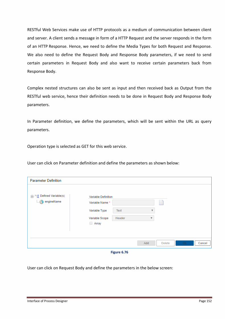
Interface of Process Designer Page 152
RESTful Web Services make use of HTTP protocols as a medium of communication between client
and server. A client sends a message in form of a HTTP Request and the server responds in the form
of an HTTP Response. Hence, we need to define the Media Types for both Request and Response.
We also need to define the Request Body and Response Body parameters, if we need to send
certain parameters in Request Body and also want to receive certain parameters back from
Response Body.
Complex nested structures can also be sent as input and then received back as Output from the
RESTful web service, hence their definition needs to be done in Request Body and Response Body
parameters.
In Parameter definition, we define the parameters, which will be sent within the URL as query
parameters.
Operation type is selected as GET for this web service.
User can click on Parameter definition and define the parameters as shown below:
Figure 6.76
User can click on Request Body and define the parameters in the below screen:

Interface of Process Designer Page 153
Figure 6.77
User can click on Response Body to define the parameters in the below screen:
Figure 6.78
User can select the authentication type from the options shown under the authentication type as
shown below:

Interface of Process Designer Page 154
Figure 6.79
If user selects Basic authentication, user is prompted to provide the User Name and Password to be
saved as shown below:
Figure 6.80

Interface of Process Designer Page 155
If user selects Token based authentication, then user will have to enter the required parameters in
the below screen, which will include the Authorization URL and the authentication token variables
to be sent for authorization as shown below:
Figure 6.81
Media types information will be used to parse the Response or prepare the Request for RESTful
web service. User can select the Request Media type as shown below:
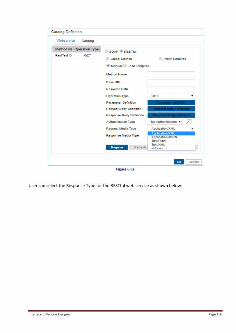
Interface of Process Designer Page 156
Figure 6.82
User can select the Response Type for the RESTful web service as shown below:
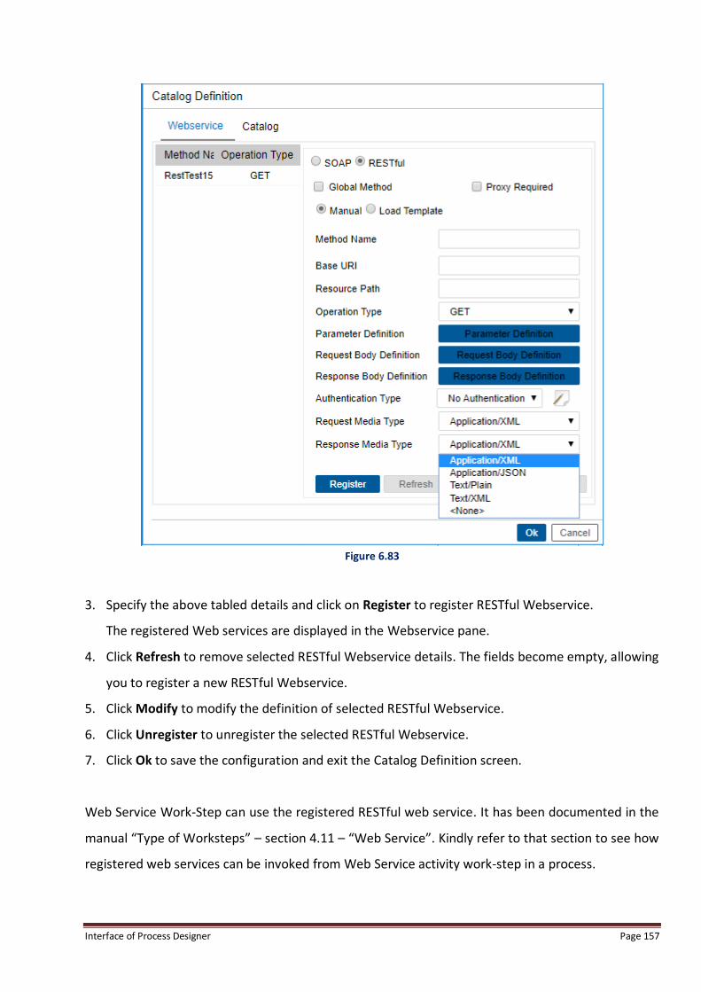
Interface of Process Designer Page 157
Figure 6.83
3. Specify the above tabled details and click on Register to register RESTful Webservice.
The registered Web services are displayed in the Webservice pane.
4. Click Refresh to remove selected RESTful Webservice details. The fields become empty, allowing
you to register a new RESTful Webservice.
5. Click Modify to modify the definition of selected RESTful Webservice.
6. Click Unregister to unregister the selected RESTful Webservice.
7. Click Ok to save the configuration and exit the Catalog Definition screen.
Web Service Work-Step can use the registered RESTful web service. It has been documented in the
manual “Type of Worksteps” – section 4.11 – “Web Service”. Kindly refer to that section to see how
registered web services can be invoked from Web Service activity work-step in a process.

Interface of Process Designer Page 158
Steps to Register WSDL Created While Registering Processes:
1. Kindly save the WSDL as a local file.
2. Change <soap12: fault to <soap: fault.
Figure 6.84
3. Import the local file in Process Designer with the local path.
4. System parses the web service.
To Register a Function:
Catalog tab will give user the interface to manage external functions. By default Process Designer
provides some useful functions which are named as System functions here. User cannot modify or
delete these. User can register his own functions using this window. Registered functions can then
be used in rules. The external functions registered by the user can also be marked as Global, i.e.
once registered, they can be used across Processes.
1. Click Catalog tab, as shown in the following figure:

Interface of Process Designer Page 159
Figure 6.85
2. Enter the Application Name.
3. Enter Method Name.
4. Click Add Parameter to define the parameters for the function being defined. This displays the
Parameter dialog box with “Click to add more parameters”, as shown in the following figure:

Interface of Process Designer Page 160
Figure 6.86
5. Enter Name and Type of parameter in the respective text fields.
6. Click Ok. The specified name and type of parameter get displayed in the List of Parameters list
in the Catalog Definition dialog box.
7. There is also a provision to define the Return Value for the function. Check the Return Value
checkbox to enter the return type of the function. The following return data types are displayed
in the Return Type selection: Integer, Long, Float, Date, Text, ShortDate, Time and Boolean.
Select the required return type from the list. Return Value can also be an array.
8. Select a Parameter in the List of Parameters, and click Remove to remove that from the
function definition.
9. Click Register to add the function into the list of Available Functions.
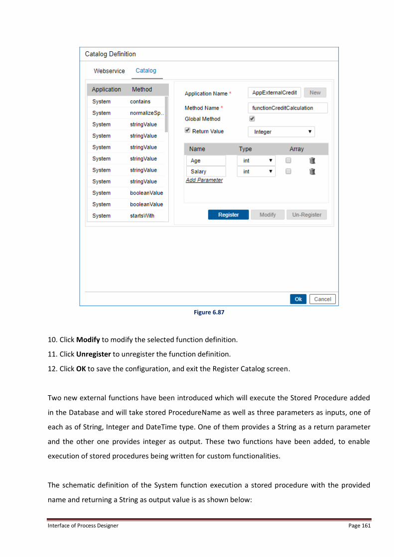
Interface of Process Designer Page 161
Figure 6.87
10. Click Modify to modify the selected function definition.
11. Click Unregister to unregister the function definition.
12. Click OK to save the configuration, and exit the Register Catalog screen.
Two new external functions have been introduced which will execute the Stored Procedure added
in the Database and will take stored ProcedureName as well as three parameters as inputs, one of
each as of String, Integer and DateTime type. One of them provides a String as a return parameter
and the other one provides integer as output. These two functions have been added, to enable
execution of stored procedures being written for custom functionalities.
The schematic definition of the System function execution a stored procedure with the provided
name and returning a String as output value is as shown below:

Interface of Process Designer Page 162
Figure 6.88
The schematic definition of the System function execution a stored procedure with the provided
name and returning a String as output value is as shown below:

Interface of Process Designer Page 163
Figure 6.89
To Register a SAP Function:
SAP tab in Register Catalog Window will allow user to register and unregister SAP functions by
logging into SAP server.
1. Click SAP tab, as shown in the following figure:-

Interface of Process Designer Page 164
Figure 6.90
2. Enter the SAP Configuration name, SAP Host Name, RFC Host Name (mark the checkbox to
enter name) SAPClient, SAPUsername, SAPPassword, Language, InstanceNo. and Function.
Figure 6.91

Interface of Process Designer Page 165
3. Click on Go on function name to populate the list of all the available functions.
4. The SAP Function List dialog box opens.
5. Choose form List All or Search on Business Object and click on Mapping button.
Figure 6.92
6. Select the desired function from the Available Function List.
7. Click Ok to select the function.
8. Click Register for registering the SAP function.
9. The Function Name appears in the Function List.

Interface of Process Designer Page 166
6.7.5 Exception To Define Exceptions:
1. Click Tools menu and then click Exception.
2. Exception definition dialog box appears.
Figure 6.93
3. Enter Exception Name.
4. Enter the Description for the exception.
5. Click Add to add the exception. The exception is added in the available Exception(s) list as
shown below:

Interface of Process Designer Page 167
Figure 6.94
6. To modify the exception, select it and make changes in its description and click Modify.
7. To delete the exception, select it and click Delete.
8. To view the Rules for a particular Exception, click Rule. The Rule Description dialog box pops up.
If the rules have been associated, the rule gets displayed.
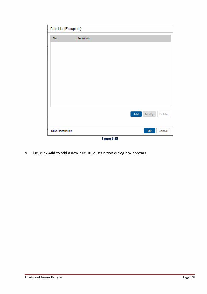
Interface of Process Designer Page 168
Figure 6.95
9. Else, click Add to add a new rule. Rule Definition dialog box appears.

Interface of Process Designer Page 169
Figure 6.96
10. Add Rule Condition and Rule Operation.
11. Click Ok to save the changes made, else click Cancel.
6.7.6 Trigger To Define and Register a Custom Trigger Type for the Current Process:
1. Go to Tools menu, and then click Trigger.
2. Trigger Definition dialog box appears.

Interface of Process Designer Page 170
Figure 6.97
3. Enter Trigger Name in Name textbox.
4. Select Type and click Define Properties . The Type can be Mail, Execute, Launch Application,
Data Entry, Set, Generate Response, Exception and CreateChildWorkitem.
NOTE:
Triggers are Process level events. They can’t be modified on Checked-out workstep.
Mail Trigger
Mail triggers allow user to send e-mail notifications with predefined message and subject text to
specified users. The predefined message and subject text can also contain variable names that are
substituted by their actual values at run time. Mail triggers can be triggered on the entry of
workitems in a workstep, or through Actions, ToDo Lists, and so on.

Interface of Process Designer Page 171
To Define a Mail Trigger:
1. Go to Options menu and then click Trigger. Trigger Definition dialog box appears.
2. Enter the Trigger Name, select Type as Mail and click on Define Properties .
3. Mail trigger dialog box appears.
Mail trigger definition
Mail triggers allow user to send e-mail notifications with predefined message and subject text to
specified users. The predefined message and subject text can also contain variable names that are
substituted by their actual values at run time. Mail triggers can be triggered on the entry of
workitems in a workstep, or through Actions, ToDo Lists, and so on.
1. Add Description for the Trigger.
2. Click Properties to define the Mail Trigger Properties. Mail trigger definition dialog box appears.
Figure 6.98
Interface of Process Designer Page 172
3. For subject of the mail, the variables (system defined, queue variables and external variables- if
an external database is introduced in the workflow) occur in the Subject combo box. Select the
variables whose value should be displayed in the Subject of the mail. Subject of the mail is
constructed at runtime. Text can also be keyed in, while variables could be included. These
variables will be substituted by their Workitem field values at the runtime.
4. Click Add to add further variables for the subject.
5. The selected variable for the subject is added where mouse cursor is located in Subject.
NOTE:
All variables added in the Subject text are enclosed within <& and &> symbols.
6. Enter From, To and CC for the mail. These combo boxes have only text type of variables and
<constant> value. User can enter the user’s mail-id either by selecting a variable from the list,
which is expected to contain a valid email address at run-time, or by typing a constant email id
by selecting <Constant> option from the combo box.
7. The variables can be user-defined (or queue) variables and external variables (if an external
database is introduced in the workflow) of type string.
8. For message of the mail, the variables (all three types of variables system defined, queue
variables and external variables) occur in the Message combo box. Select the variables whose
value should be displayed in the message of the mail and also enter the mail contents.
9. Message can be specified as the concatenation of text entered and the Variables selected from
the drop down list. While generating the actual mail, names of the variables in the message
body will be replaced by their actual value.
10. Click Ok to define the mail trigger properties, else click Cancel.
11. In Trigger Definition screen, click Add to add the mail trigger.
12. The trigger is added in Available Trigger(s) list.

Interface of Process Designer Page 173
Execute Trigger
Execute triggers allow user to execute worksteps.
To define Execute Trigger:
1. Go to Options menu and then click Trigger. Trigger Definition dialog box is invoked.
2. Enter the Trigger Name and select Type as Execute.
3. Click Define Properties .
4. Execute trigger definition dialog box appears.
5. Enter the Trigger Name and Function Name.
6. Enter the Executable class name of the window in Server Executable.
7. Choose the Arguments String, from the drop-down menu.
8. Click on Ok to define the Execute trigger properties, else click Cancel.
Figure 6.99
9. In Trigger Definition screen, click Add to add the Execute trigger.
10. Execute trigger is added in Available Trigger(s) list.

Interface of Process Designer Page 174
NOTE:
The registered Custom Trigger is displayed in the Available Trigger Types.
Launch Application Trigger
Launch Application Trigger is used to launch the specified application along with the specified
command-line argument string. All the three types of variables such as, system variables, queue
variables and external variables can be used for entering Argument String.
To define a Launch Application trigger:
Figure 6.100
1. Enter trigger Name and Description.
2. Select the Launch Application option from Type dropdown box
3. Click Properties . Launch Application dialog box appears.
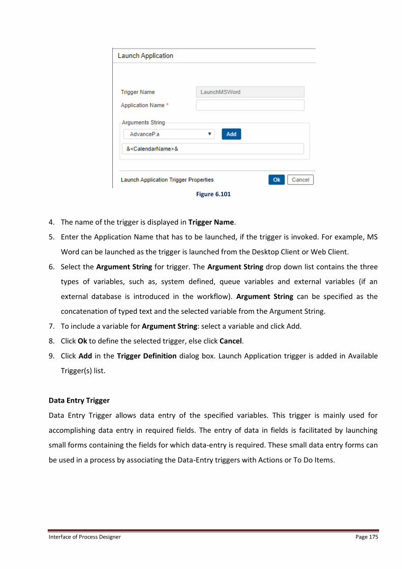
Interface of Process Designer Page 175
Figure 6.101
4. The name of the trigger is displayed in Trigger Name.
5. Enter the Application Name that has to be launched, if the trigger is invoked. For example, MS
Word can be launched as the trigger is launched from the Desktop Client or Web Client.
6. Select the Argument String for trigger. The Argument String drop down list contains the three
types of variables, such as, system defined, queue variables and external variables (if an
external database is introduced in the workflow). Argument String can be specified as the
concatenation of typed text and the selected variable from the Argument String.
7. To include a variable for Argument String: select a variable and click Add.
8. Click Ok to define the selected trigger, else click Cancel.
9. Click Add in the Trigger Definition dialog box. Launch Application trigger is added in Available
Trigger(s) list.
Data Entry Trigger
Data Entry Trigger allows data entry of the specified variables. This trigger is mainly used for
accomplishing data entry in required fields. The entry of data in fields is facilitated by launching
small forms containing the fields for which data-entry is required. These small data entry forms can
be used in a process by associating the Data-Entry triggers with Actions or To Do Items.

Interface of Process Designer Page 176
To Define a Data Entry Trigger:
1. Enter the Trigger Name and Description.
2. Select Data Entry option from Type dropdown box.
3. Click Properties. The Data entry Trigger definition dialog box appears.
Figure 6.102
4. The list of user defined (or queue) variables and the external variables (if the external database
is introduced in the workflow) are displayed. Select the variables for which the data entry has to
be provided.
5. Click Ok to save the changes made, else click Cancel.
6. Click Add in the Trigger Definition dialog box. The trigger is added in Available Trigger(s) list.
Set Trigger
Set trigger is used for setting a variable with a specified value or with the value of any other
variable. This trigger sets values for user-defined variables and external variables. When the trigger
is invoked, the values specified for these variables are automatically set for the workitem in the
process.

Interface of Process Designer Page 177
To Define Set Trigger:
1. Enter the trigger Name and Description.
2. Select Set option from Type dropdown box.
3. Click Properties. Set Trigger dialog box appears.
Figure 6.103
4. Select the variable whose value has to be set from Field drop down list. The list displays all the
user-defined (queue) variables, and all external variables (if any).
5. Select value for the variable from the Value drop down list. The list displays all the constants,
user-defined (queue) variables and external variables (if the external database is introduced in
the workflow). This is an editable combo box where user can enter a constant value by selecting
the <Constant> option or enter a variable by selecting a variable from the list.
6. Click Add to add the field and value equation for the trigger. The equation is displayed in the
Variable List.
7. To modify an already defined equation: Select the equation and made the changes. Click Modify
to save the changes made.
8. Click Delete to delete the selected equation from the Variable list.
9. Click Ok to define the selected trigger, else click Cancel.
10. Click Add in Trigger Definition dialog box. The trigger is added in Available Trigger(s) list.

Interface of Process Designer Page 178
Generate Response Trigger
Generate Response Trigger is used for generating Response Letters in a process, based on certain
predefined Word Template. These Response Letters can also be added to the workitem as
documents of specified Document Types. Thus the user can define and register word templates and
use them in this trigger.
NOTE:
A word template is a word document, which may contain process variable names, which through the Generate
Response Trigger, will get replaced with their actual values for the work-item.
To Define a Generate Response Trigger:
1. Enter the trigger Name and Description.
2. Select Generate Response option from Type dropdown list.
3. Click Properties. The Generate Response Trigger dialog box appears.
Figure 6.104
4. Enter the Application Name. Typically an application is MSWord, or WinWord.
5. Select the File Name (name of the template for which the document is to be generated) with
.doc extension. This file appears only after registering the file through Registering Template
option. It will display all already Registered Templates in the process.
6. Select any defined Document Type. This is the document by which template will be added in
the workitem. In case, user select the <None> option then the WorkDesk will generate the
document, and open the same. When the user closes the document, the system pops-up a list

Interface of Process Designer Page 179
of all Document Types (addable on that workstep), prompting him to associate the Document
Type at run-time.
7. Click Ok to save the changes made, else click Cancel.
8. Click Add in Trigger Definition dialog box. The trigger is added in Available Trigger(s) list.
Exception Trigger
Exception Trigger is used for raising or clearing exceptions with comments, on occurrence of certain
events, like Actions, ToDo Lists, Rules, and so on. When this trigger is executed, the defined
exception is raised or cleared with specified comments.
To define an exception trigger, at least one exception should be defined in the process. To learn
about defining exceptions, refer section Exception.
To Define an Exception Trigger:
Figure 6.105
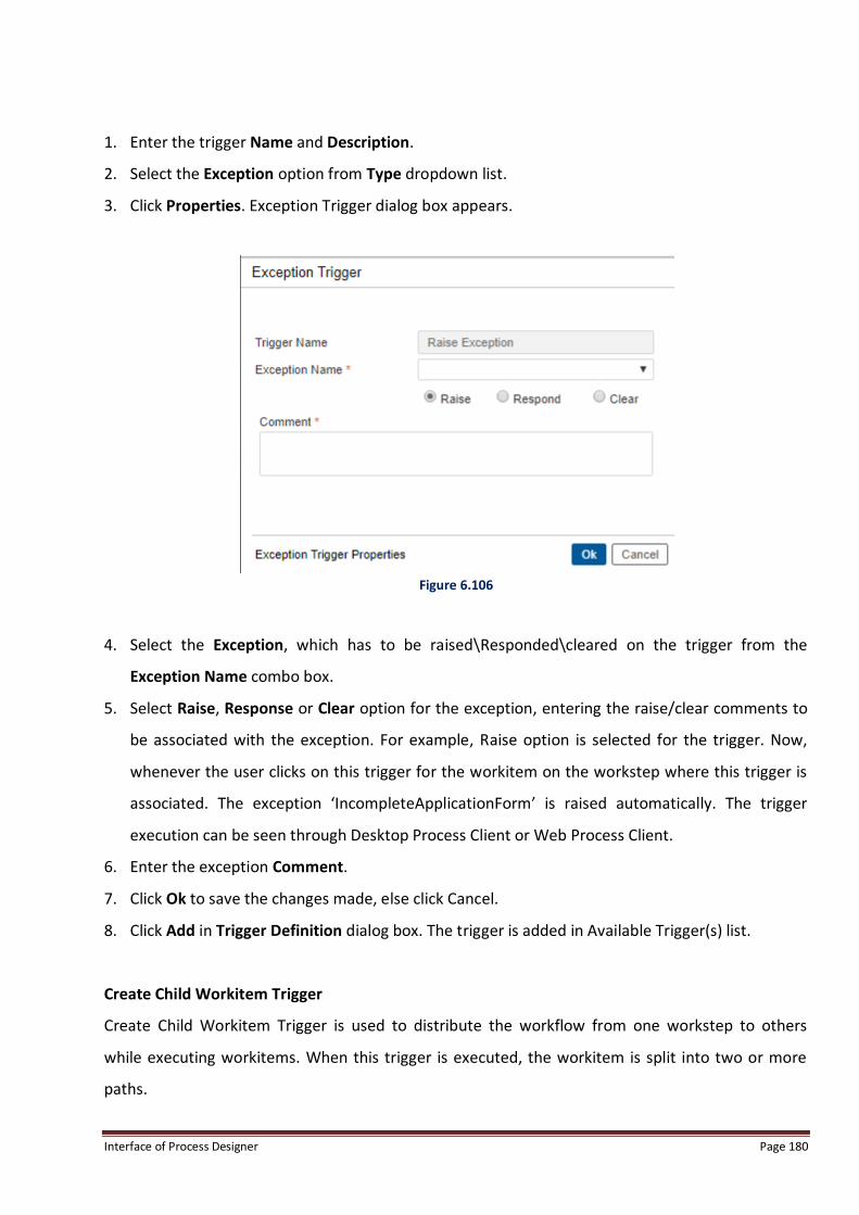
Interface of Process Designer Page 180
1. Enter the trigger Name and Description.
2. Select the Exception option from Type dropdown list.
3. Click Properties. Exception Trigger dialog box appears.
Figure 6.106
4. Select the Exception, which has to be raised\Responded\cleared on the trigger from the
Exception Name combo box.
5. Select Raise, Response or Clear option for the exception, entering the raise/clear comments to
be associated with the exception. For example, Raise option is selected for the trigger. Now,
whenever the user clicks on this trigger for the workitem on the workstep where this trigger is
associated. The exception ‘IncompleteApplicationForm’ is raised automatically. The trigger
execution can be seen through Desktop Process Client or Web Process Client.
6. Enter the exception Comment.
7. Click Ok to save the changes made, else click Cancel.
8. Click Add in Trigger Definition dialog box. The trigger is added in Available Trigger(s) list.
Create Child Workitem Trigger
Create Child Workitem Trigger is used to distribute the workflow from one workstep to others
while executing workitems. When this trigger is executed, the workitem is split into two or more
paths.
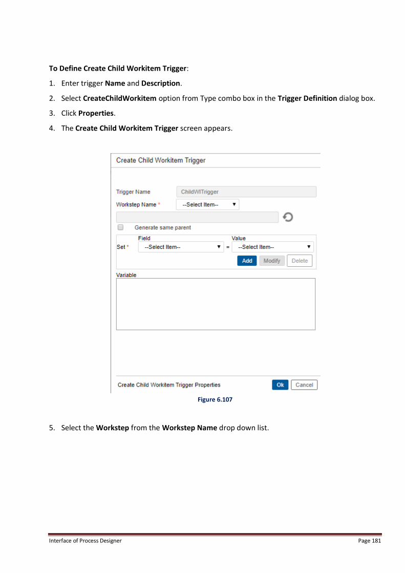
Interface of Process Designer Page 181
To Define Create Child Workitem Trigger:
1. Enter trigger Name and Description.
2. Select CreateChildWorkitem option from Type combo box in the Trigger Definition dialog box.
3. Click Properties.
4. The Create Child Workitem Trigger screen appears.
Figure 6.107
5. Select the Workstep from the Workstep Name drop down list.
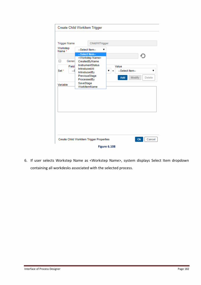
Interface of Process Designer Page 182
Figure 6.108
6. If user selects Workstep Name as <Workstep Name>, system displays Select Item dropdown
containing all workdesks associated with the selected process.
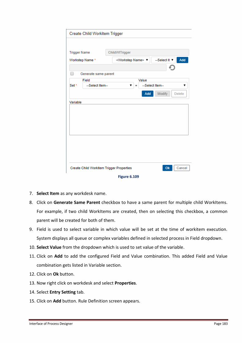
Interface of Process Designer Page 183
Figure 6.109
7. Select Item as any workdesk name.
8. Click on Generate Same Parent checkbox to have a same parent for multiple child WorkItems.
For example, if two child WorkItems are created, then on selecting this checkbox, a common
parent will be created for both of them.
9. Field is used to select variable in which value will be set at the time of workitem execution.
System displays all queue or complex variables defined in selected process in Field dropdown.
10. Select Value from the dropdown which is used to set value of the variable.
11. Click on Add to add the configured Field and Value combination. This added Field and Value
combination gets listed in Variable section.
12. Click on Ok button.
13. Now right click on workdesk and select Properties.
14. Select Entry Setting tab.
15. Click on Add button. Rule Definition screen appears.
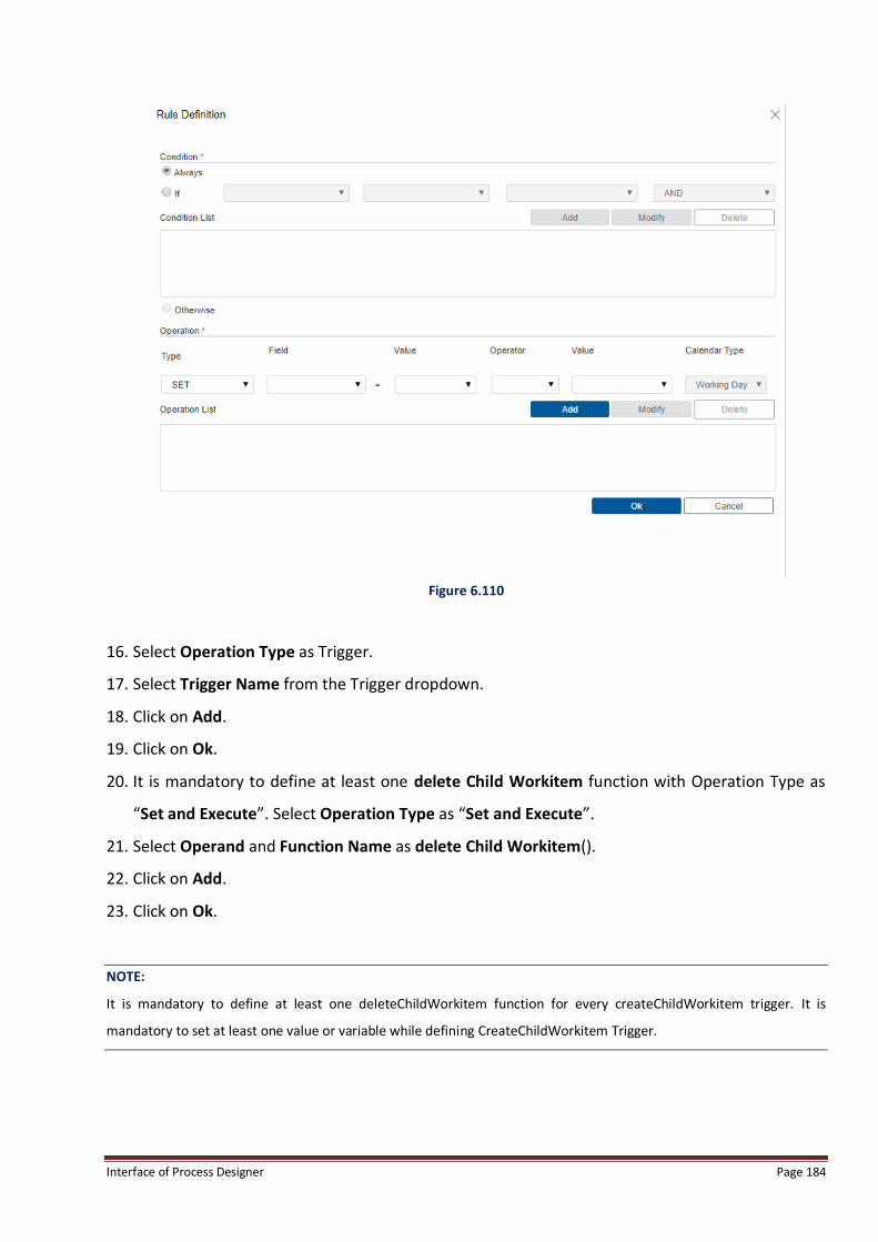
Interface of Process Designer Page 184
Figure 6.110
16. Select Operation Type as Trigger.
17. Select Trigger Name from the Trigger dropdown.
18. Click on Add.
19. Click on Ok.
20. It is mandatory to define at least one delete Child Workitem function with Operation Type as
“Set and Execute”. Select Operation Type as “Set and Execute”.
21. Select Operand and Function Name as delete Child Workitem().
22. Click on Add.
23. Click on Ok.
NOTE:
It is mandatory to define at least one deleteChildWorkitem function for every createChildWorkitem trigger. It is
mandatory to set at least one value or variable while defining CreateChildWorkitem Trigger.

Interface of Process Designer Page 185
To Modify Trigger:
1. Select the trigger which needs to be modified and click Modify.
2. User can only modify the Properties and the description of the Trigger.
To Delete Trigger:
1. Select the trigger that has to be deleted and click Delete. The message box is invoked for
confirmation.
2. Click Yes to delete. After deletion the trigger occurrences will also be deleted.
3. Click OK to save the changes made.
6.7.7 Register Template To Register a Template in a Local Process:
1. Go to Tools menu, and then click Register Template. Register Template dialog box appears.
NOTE:
If user wants to download template in PDF format through Generate Response Trigger, then they need to set flag
GenerateResponsePdf = Yes under webdesktop.ini.
Figure 6.111

Interface of Process Designer Page 186
2. Click Choose File to select and add the template.
3. Select Doc (Word file)/PDF, which has to be defined as template and click Open.
4. Select Document to be associated with this template.
5. Select Format of the uploaded document.
6. Choose Argument from the available list of system and user defined arguments by clicking on
.
Figure 6.112
7. Click Add to associate the template. The system displays a message: Template Added
Successfully. The Template Name and Template Type would be displayed in the table.
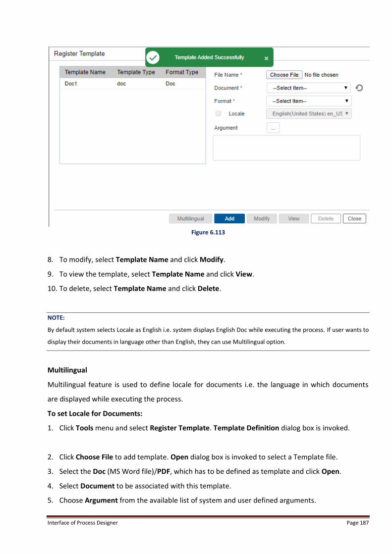
Interface of Process Designer Page 187
Figure 6.113
8. To modify, select Template Name and click Modify.
9. To view the template, select Template Name and click View.
10. To delete, select Template Name and click Delete.
NOTE:
By default system selects Locale as English i.e. system displays English Doc while executing the process. If user wants to
display their documents in language other than English, they can use Multilingual option.
Multilingual
Multilingual feature is used to define locale for documents i.e. the language in which documents
are displayed while executing the process.
To set Locale for Documents:
1. Click Tools menu and select Register Template. Template Definition dialog box is invoked.
2. Click Choose File to add template. Open dialog box is invoked to select a Template file.
3. Select the Doc (MS Word file)/PDF, which has to be defined as template and click Open.
4. Select Document to be associated with this template.
5. Choose Argument from the available list of system and user defined arguments.

Interface of Process Designer Page 188
6. Click Add to associate the template.
7. Select added document and select checkbox against Locale.
8. Select Language.
Figure 6.114
9. Click on Multilingual button.
10. System displays Message “Multilingual Template Added Successfully”.
Figure 6.115
In the above case, system will display the selected document in Japanese Language during process
execution.

Interface of Process Designer Page 189
6.7.8 Register Window To Register New Window for the Current Process:
1. Point to Tools menu, and then click Register Window.
2. Register Windows dialog box appears.
Figure 6.116
3. Enter the Name for the new window.
4. Enter the Http Path and Table Names.
5. Enter the Executable class name of the window in Execution Interface.
NOTE:
iBPS provides a framework to extend the properties of worksteps, through the Register Window functionality. However
it is the responsibility of the implementer to design the Design-Time Property Window for storing the properties of the
window in the process, and a corresponding run-time Execution Window for being launched to display the required
interface in the Workdesk. The Window Name, Property Class Name, and Executable Class Name specified should be
unique across all windows.
6. Enter the Http path of jsp, which will be launched as the run-time execution window when the
workitem is opened from the Web WorkDesk.
7. Enter menu caption for the window in Menu Name. This is the name that would appear as a
menu option in the iBPSWorkDesk.
8. Click Register to register the window.
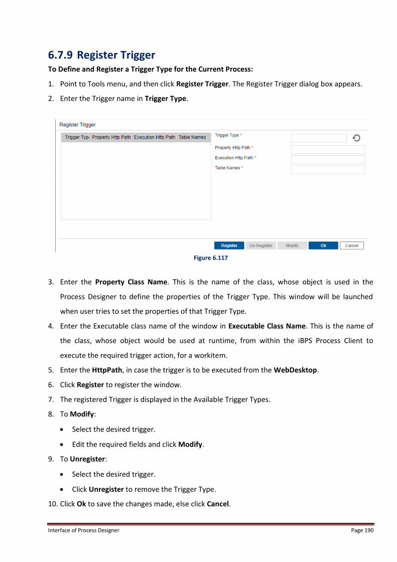
Interface of Process Designer Page 190
6.7.9 Register Trigger To Define and Register a Trigger Type for the Current Process:
1. Point to Tools menu, and then click Register Trigger. The Register Trigger dialog box appears.
2. Enter the Trigger name in Trigger Type.
Figure 6.117
3. Enter the Property Class Name. This is the name of the class, whose object is used in the
Process Designer to define the properties of the Trigger Type. This window will be launched
when user tries to set the properties of that Trigger Type.
4. Enter the Executable class name of the window in Executable Class Name. This is the name of
the class, whose object would be used at runtime, from within the iBPS Process Client to
execute the required trigger action, for a workitem.
5. Enter the HttpPath, in case the trigger is to be executed from the WebDesktop.
6. Click Register to register the window.
7. The registered Trigger is displayed in the Available Trigger Types.
8. To Modify:
Select the desired trigger.
Edit the required fields and click Modify.
9. To Unregister:
Select the desired trigger.
Click Unregister to remove the Trigger Type.
10. Click Ok to save the changes made, else click Cancel.

Interface of Process Designer Page 191
6.7.10 Property Association To define the property associated with various activities like data variables, ToDo, Documents,
Exceptions and forms.
1. Go to Tools menu, and then click Property Association.
2. The Activity Association (Process Name) dialog box appears.
To Do Tab: To update View and Read Only rights on To Dos associated with each activity.
1. Mark the checkbox and point to to provide Modify and ReadOnly rights on ToDos
associated with the activities.
2. Click Save to save the changes.
Figure 6.118

Interface of Process Designer Page 192
Data Tab: To update Read and Modify rights on data rights associated with each activity.
1. Click to provide Read and Modify rights on the activities associated with the Data.
2. Click Save to save the changes.
Document Tab: To update view and modify rights on documents associated with each activity.
Add, View and Modify rights can be associated with the document.
NOTE:
For Case Summary Document, the user will have View rights on all activities as it is system generated.
Exception Tab: To update rights on exceptions associated with each activity.
View, Raise, Respond and Clear can be associated with the Exception activities.
Form Tab: To update form associated with each activity.
View Rights are associated with the Form activity.
6.7.11 Default Queues for Activity Automatically creates separate queue for all activities if the checkbox against Default Queues for
Activity is selected.
If user deselects checkbox against Default Queues for Activity for a particular swimlane, he has to
manually create separate queue for new activities except reply and workdesk.
NOTE:
On de-selection of checkbox against “Default Queues for Activity”, existing queues for predefined activities will not be
deleted.
If user selects checkbox against “Default Queues for Activity” for a particular swimlane, system will automatically create
separate queue for all activities present in selected swimlane.

Interface of Process Designer Page 193
Figure 6.119
6.7.12 Register SAP Details To Register SAP Details:
1. Go to Tools-> Register SAP details. SAP Details window to configure SAP appears.

Interface of Process Designer Page 194
Figure 6.120
2. Enter all the details like SAPConfiguration, SAPHostName, RFC Host Name(Mark the checkbox
to enter name), SAPUserName, SAPPassword,Language, Port,. InstanceNo., SAPClient and
HTTP Port details.
3. Select SAP Protocol and SAP ITS Server options as required.
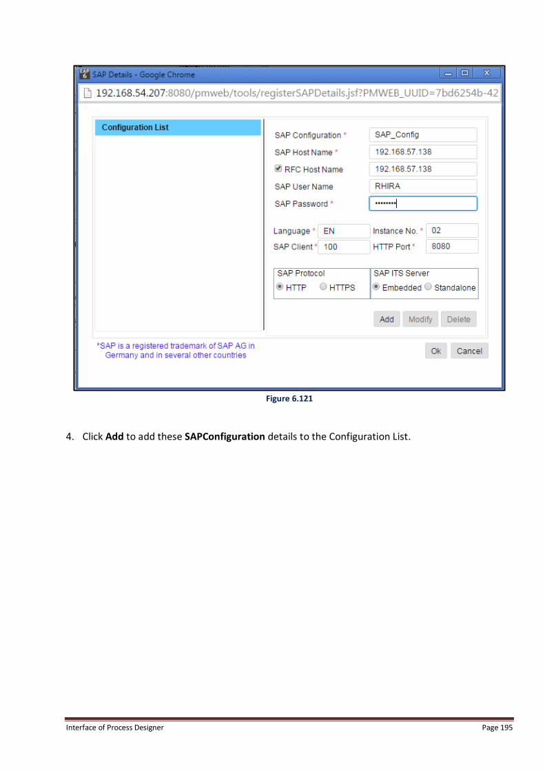
Interface of Process Designer Page 195
Figure 6.121
4. Click Add to add these SAPConfiguration details to the Configuration List.

Interface of Process Designer Page 196
Figure 6.122
5. Click Ok to register and close the screen.
6.7.13 Register BRT Details (For Registered Process Only) Register BRT (Business Rule Task) Details is used to create a URL for accessing process at any other
place except source location. E.g. If a process is moved to a different server, then the WSDL IPs
being used by the process to call BRMS APIs will point to the old server on which Process was being
hosted. Thus, in case of process movement, BRT details can be changed to make the process point
to different BRMS server, e.g. new server on which process has been deployed.
To Register BRT Details:
1. Go to Tools -> Register BRT Details.
2. Register BRT Details screen appears. It containing following fields:
Configuration: This field is used to enter server name, by default it is “localserver”.
Host Name: This field is used to enter IP Address of the server.

Interface of Process Designer Page 197
HTTP Port: This field is used to enter HTTP port number.
Protocol: This field allow user to select Protocol as HTTP or HTTPS.
Proxy Enabled: If user selects checkbox against “Proxy Enabled”, user needs to enter username
and password for accessing process activities.
Username: This field allows user to enter username for accessing process activities.
Password: This field allows user to enter password for accessing process activities.
3. Following two buttons are displayed in the bottom of the screen:
Save: This button saves the entered information.
Close: This button closes the current window and return user to the Process Designer Interface.
Figure 6.123
6.7.14 Global Task Template When defining tasks, user can save them as global templates. User can also define global templates
separately for use in processes. When user saves a task as a global template, it is made available
across the cabinet. Thus, it can be used by any user for any process.
To Add a Global Template:
1. Go to Tools->Global Task Template.
2. Global Task Template dialog box appears.

Interface of Process Designer Page 198
Figure 6.124
3. Global Templates section, in left pane of the screen, contains the existing global task templates.
4. The right pane of the screen displays fields to define properties of the global task.
5. Enter Template Name and specify details in Task, Data, Options and Escalation Rule(s) tabs.
6. Click on Add Global Template button.
Figure 6.125

Interface of Process Designer Page 199
7. A confirmation message “Template Added Successfully” is displayed and the new template gets
listed under Global Templates.
Figure 6.126
8. Click on Ok to close the Global Task Template screen. The created task will now be available for
use across cabinet.
NOTE:
Adding at least one process variable, a goal and an instruction is mandatory for creating a task template.
If NGForm or IForm option is selected in Data tab but no form is created for the same, then an alert message specifying
that "Custom form has not been created" is displayed at the top of the screen. To add or view/edit form, refer to
Creating Form.
Task Tab
To Specify Task Details:
a. Click on Task tab. The task tab appears.
b. Specify the following details:

Interface of Process Designer Page 200
Description: Specify the description of the task.
Goal: Specify the task goal.
Instructions: Specify instructions to complete the task.
Repeatable: If checked, the task can be used again and again by other users also. If
unchecked, the task will be used only once.
Notify By Email: If checked, task notifications will be sent to the task user through
emails.
Turnaround Time: Allows you to enter TAT (Turnaround Time) in days, hours and
minutes either using working days or calendar days.
Cost ($): Allows you to specify cost to complete this task.
Task Advisor: Allows you to appoint a single or multiple task advisors. To select a Task
Advisor:
Click on button . Select User window pops-up.
Click on the desired user name to select it. The name of the selected user appears in
the textbox.
Click on (Add) button to add more Task Advisors.
Click on (Remove) against the desired task advisor to remove it.
Figure 6.127

Interface of Process Designer Page 201
Data Tab
To Add Task Data:
a. Click on Data tab. The Data tab appears.
b. Select NONE option if Default HTML Form has to be used. Select NGForm/IForm option if an
NGForm/IForm form has to be uploaded/created for the Task. Refer to Creating Form to
Upload or View/Edit form.
c. Click on Addvariable(s) to specify variables.
Enter Variable Name.
Select the Variable Type.
Enter Display Name. It is disabled for NGForm/IForm.
Select Control Type as TextBox, TextArea or Combo. It is disabled for NGForm/IForm.
Figure 6.128

Interface of Process Designer Page 202
Delete Data Variables:
Select the checkboxes against the desired variables and click on Delete variable(s).
Figure 6.129
Modify Button is to modify and save the complete Template and not for individual task template variables.
Options Tab
Options tab is used to set date and time for task expiry. As soon as the expiry period is hit, the
trigger will fire and the associated action will be completed.
1. Click on Options tab. The selected tab appears.
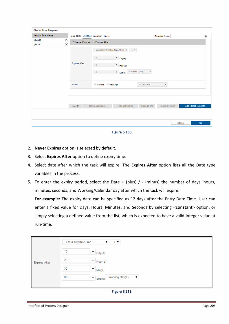
Interface of Process Designer Page 203
Figure 6.130
2. Never Expires option is selected by default.
3. Select Expires After option to define expiry time.
4. Select date after which the task will expire. The Expires After option lists all the Date type
variables in the process.
5. To enter the expiry period, select the Date + (plus) / - (minus) the number of days, hours,
minutes, seconds, and Working/Calendar day after which the task will expire.
For example: The expiry date can be specified as 12 days after the Entry Date Time. User can
enter a fixed value for Days, Hours, Minutes, and Seconds by selecting <constant> option, or
simply selecting a defined value from the list, which is expected to have a valid integer value at
run-time.
Figure 6.131

Interface of Process Designer Page 204
6. Specify Action.
i. Revoke: On expiry, the task will be revoked automatically and an email will be sent to Case
Manager, task initiator and task worker.
Figure 6.132
ii. Reassign: On expiry, the task will be reassigned to the corresponding user associated with
the action. The task can also be reassigned to Case Manager/Task Initiator.
Enter a fixed person for Reassign by selecting <constant> option, or simply select a
person from the combo box.
Figure 6.133
7. Select Trigger to invoke trigger on expiry. List of available triggers is displayed.
Figure 6.134
8. As soon as the expiry period is hit, the trigger is fired and the associated action is completed.
Escalation Rule(s) Tab
Escalation Rule(s) tab allows you to define escalation rules for a task which breaches its deadline or
is reaching a deadline.
To Define Escalation Rules:
1. Click on Escalation Rule(s) tab. The selected tab appears.

Interface of Process Designer Page 205
Figure 6.135
2. Click on Add to add escalation rules. Escalation Rule dialog box appears.
Figure 6.136
3. Specify the time period after which the Escalation will be invoked.
Select the Date + (plus) the number of days, hours, minutes, seconds, and Calendar Type
(Working/Calendar day) after which the task will be escalated.
Enter a fixed value for Date, Days, Hours, Minutes, and Seconds by selecting <constant>
option or select options from the respective combo boxes. It lists all the Date type variables
in the process.

Interface of Process Designer Page 206
4. Click on Configure Mail Template to define a mail template, using which an email will be sent to
the Supervisor or the Team Leader for the escalated task.
Escalate Mail Template dialog box appears. Here you can draft the escalation mail to be
triggered.
5. Specify From, To and Subject fields as these are mandatory to fill. Remaining fields can be
specified as required.
NOTE:
Select <Constant> to type the fields manually.
Figure 6.137
6. Click on Add to save the mail template. The control returns back to Escalation Rule dialog box.

Interface of Process Designer Page 207
Figure 6.138
7. Click on Ok to save the defined Escalation Rule. The rule gets listed in Escalation Rule(s).
Figure 6.139
NOTE:
A user can define multiple escalation rules for each task.

Interface of Process Designer Page 208
Creating Form
To Upload Form or View/Edit Form:
1. Click on the required task template listed in Global Task Templates. The properties of the
selected task template appear in right pane of the screen.
2. Upload Form and View/Edit Form buttons are enabled.
NOTE:
Upload Form and View/Edit Form tabs are disabled if Default HTML Form option was selected in Data tab.
Figure 6.140
a. Upload Form
Click on Upload Form button to upload pre-designed form (NGForm/IForm).
Upload Form dialog box appears.

Interface of Process Designer Page 209
Figure 6.141
Click on Choose File button to select the form for uploading.
NOTE:
For NGForm, .ngf type form is allowed to be uploaded. For IForm, .xml type form is allowed to be uploaded.
Dialog box to select the form appears.
Select the desired form (NGForm/IForm) and click on Ok. The uploaded form appears in
FormBuilder/IFormBuilder.
Click on Back to Global Template to return to Global Task Template.
NOTE:
Refer to Form Builder and iForm Builder user manuals to learn about the two form types.

Interface of Process Designer Page 210
Figure 6.142: iForm
Figure 6.143: NGForm

Interface of Process Designer Page 211
b. View/Edit Form: It is used to view or edit the existing form associated with the task.
Click on View/Edit Form button to view or edit the existing form (NGForm/IForm).
The FormBuilder screen appears. If there is any associated NGForm/IForm form, then
that form appears in edit mode. If there is no associated NGForm/IForm form, then a
blank page appears, allowing you design a new form.
Modify the form (NGForm/IForm) as required and save it.
To Modify a Global Task Template:
1. Go to Tools->Global Task Template. Global Task Template screen appears.
2. Select the desired TaskTemplate. The selected task template opens in edit mode and Modify
button gets enabled.
Figure 6.144
3. Edit the task properties consisting of Task, Data, Options and Escalation Rule(s).
4. Click on Modify to save the modified template data. A message, “Template Modified
Successfully”, appears.

Interface of Process Designer Page 212
Figure 6.145
To Delete a Global Task Template:
1. Go to Tools->Global Task Template. Global Task Template screen appears.
2. Click on Delete button against the desired global task.
Figure 6.146
3. The deleted global task gets removed from the list of Global Templates.
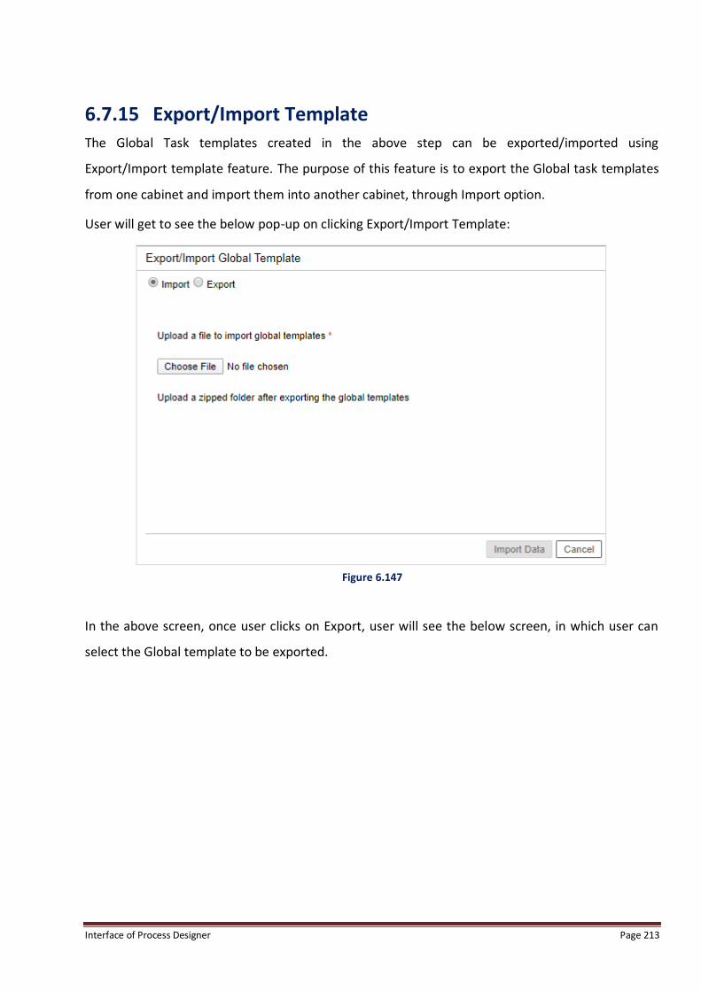
Interface of Process Designer Page 213
6.7.15 Export/Import Template
The Global Task templates created in the above step can be exported/imported using
Export/Import template feature. The purpose of this feature is to export the Global task templates
from one cabinet and import them into another cabinet, through Import option.
User will get to see the below pop-up on clicking Export/Import Template:
Figure 6.147
In the above screen, once user clicks on Export, user will see the below screen, in which user can
select the Global template to be exported.

Interface of Process Designer Page 214
Figure 6.148
Once, user clicks on Export, user will see the below message, while the export is going on:
Figure 6.149
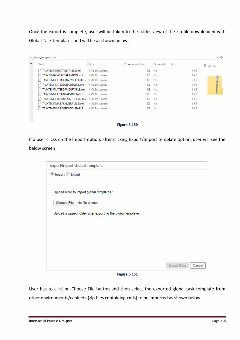
Interface of Process Designer Page 215
Once the export is complete, user will be taken to the folder view of the zip file downloaded with
Global Task templates and will be as shown below:
Figure 6.150
If a user clicks on the Import option, after clicking Export/Import template option, user will see the
below screen
Figure 6.151
User has to click on Choose File button and then select the exported global task template from
other environments/cabinets (zip files containing xmls) to be imported as shown below:

Interface of Process Designer Page 216
Figure 6.152
If user clicks on Overwrite and then clicks on Ok in the pop-up message below:
Figure 6.153
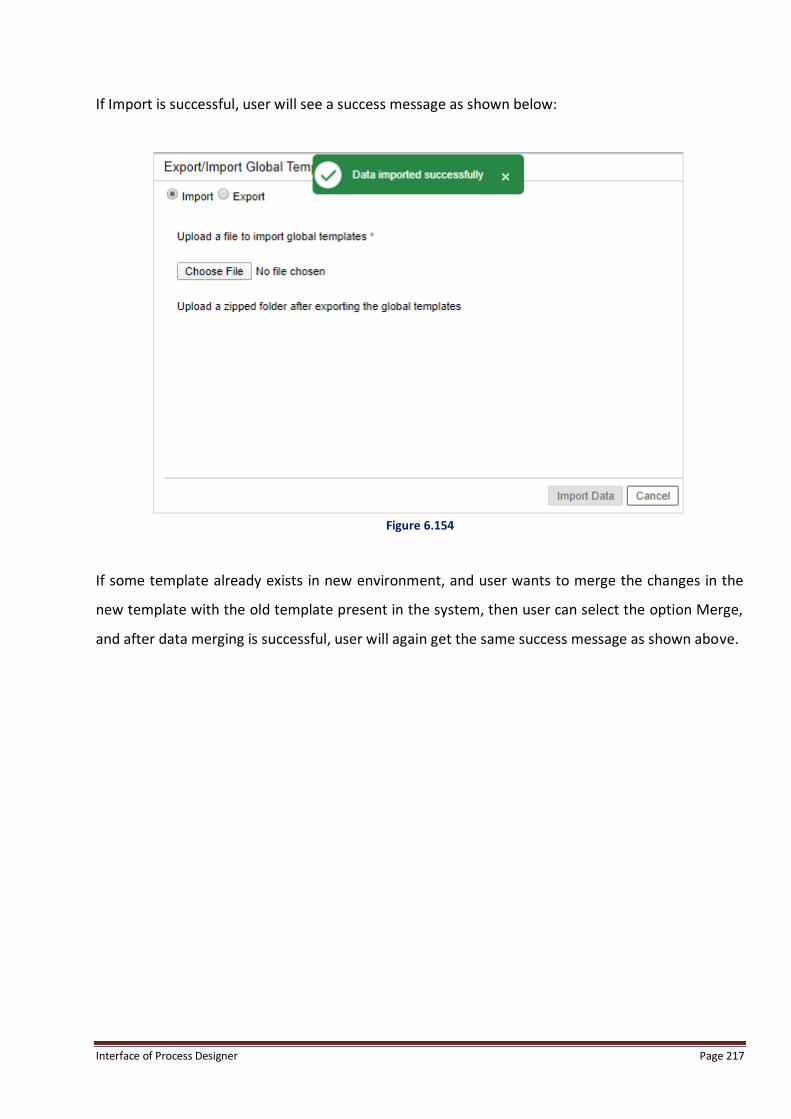
Interface of Process Designer Page 217
If Import is successful, user will see a success message as shown below:
Figure 6.154
If some template already exists in new environment, and user wants to merge the changes in the
new template with the old template present in the system, then user can select the option Merge,
and after data merging is successful, user will again get the same success message as shown above.

Interface of Process Designer Page 218
6.8 Admin The Admin Menu is shown in the following figure:
Figure 6.155
The Admin menu has the following options:
Deploy: A process must be deployed to make it live. This option invokes Deploy Process dialog
box for deploying the process in the connected remote database.
Validate Process: Allows the validation of a registered process. Invalid information refers to the
invalid information (rule etc) caused by deleting a variable, trigger, and deleting a workstep or a
link. For example, if a rule consists of a variable and that variable is deleted later, then the
corresponding rule becomes invalid. This sub-menu item invokes the Invalid Information dialog
box for displaying any invalid information, if any, present in the process and cause behind
invalidation.
Maker Checker: If user wants to change process state, queue level, he can perform the
operation using Maker Checker option. When a process is registered, the process can be
enabled to be introduced in Maker-checker now. Enabling a registered process means that it is
introduced in the maker-checker queue and a process is ready for execution.
6.8.1 Deploy Refer section Deploy Process.
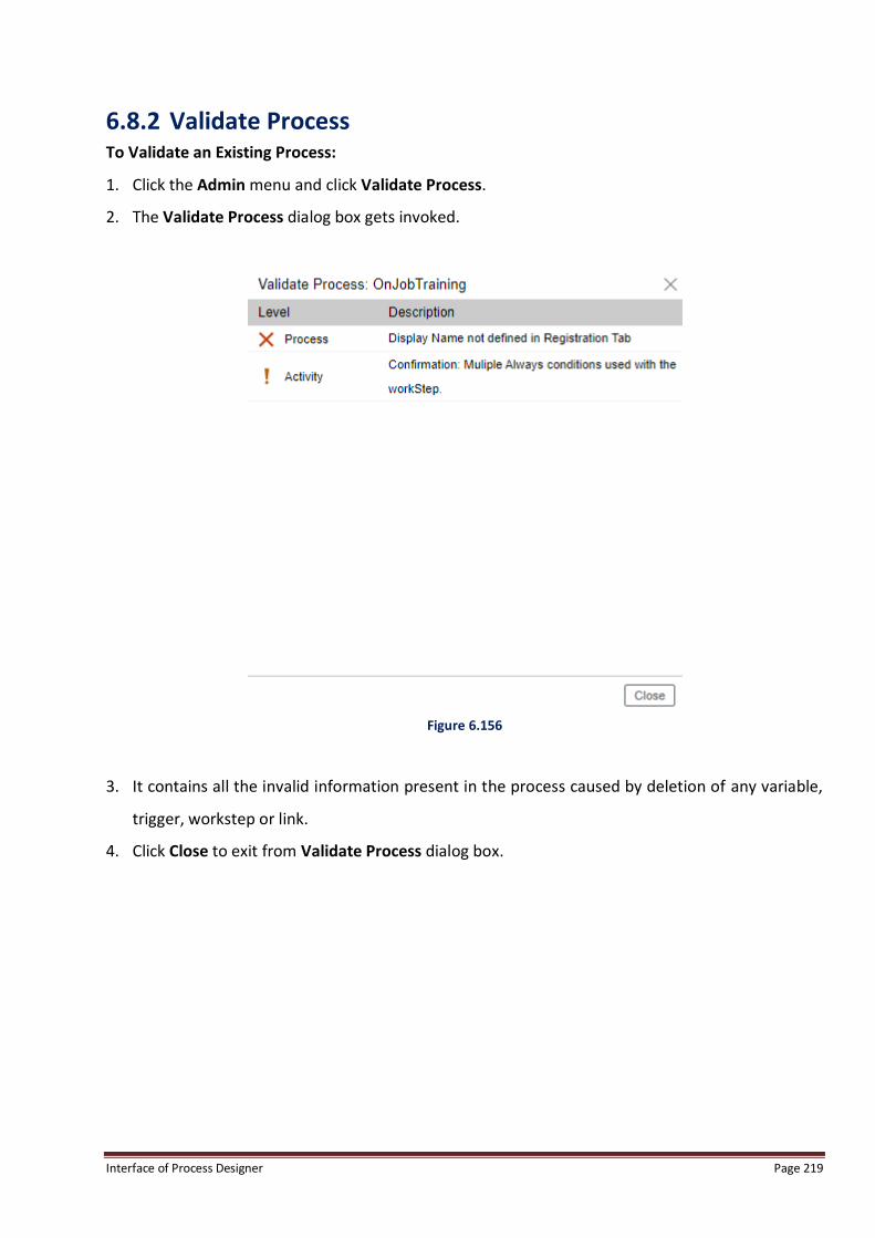
Interface of Process Designer Page 219
6.8.2 Validate Process To Validate an Existing Process:
1. Click the Admin menu and click Validate Process.
2. The Validate Process dialog box gets invoked.
Figure 6.156
3. It contains all the invalid information present in the process caused by deletion of any variable,
trigger, workstep or link.
4. Click Close to exit from Validate Process dialog box.
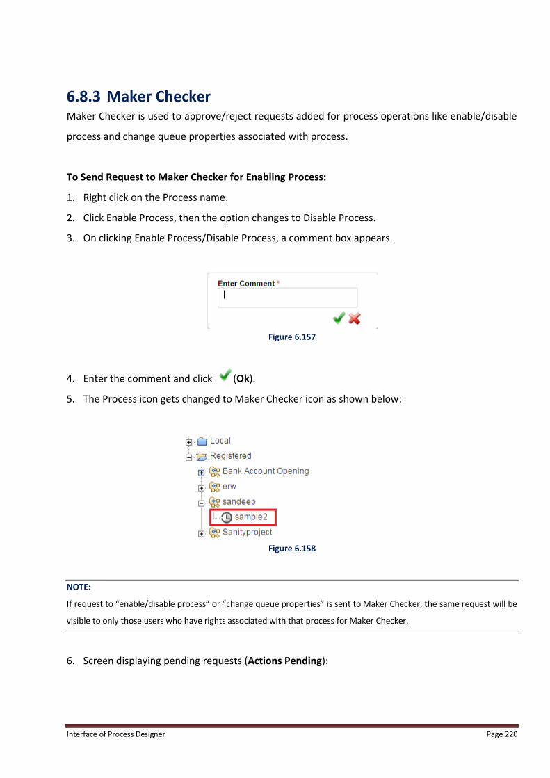
Interface of Process Designer Page 220
6.8.3 Maker Checker Maker Checker is used to approve/reject requests added for process operations like enable/disable
process and change queue properties associated with process.
To Send Request to Maker Checker for Enabling Process:
1. Right click on the Process name.
2. Click Enable Process, then the option changes to Disable Process.
3. On clicking Enable Process/Disable Process, a comment box appears.
Figure 6.157
4. Enter the comment and click (Ok).
5. The Process icon gets changed to Maker Checker icon as shown below:
Figure 6.158
NOTE:
If request to “enable/disable process” or “change queue properties” is sent to Maker Checker, the same request will be
visible to only those users who have rights associated with that process for Maker Checker.
6. Screen displaying pending requests (Actions Pending):
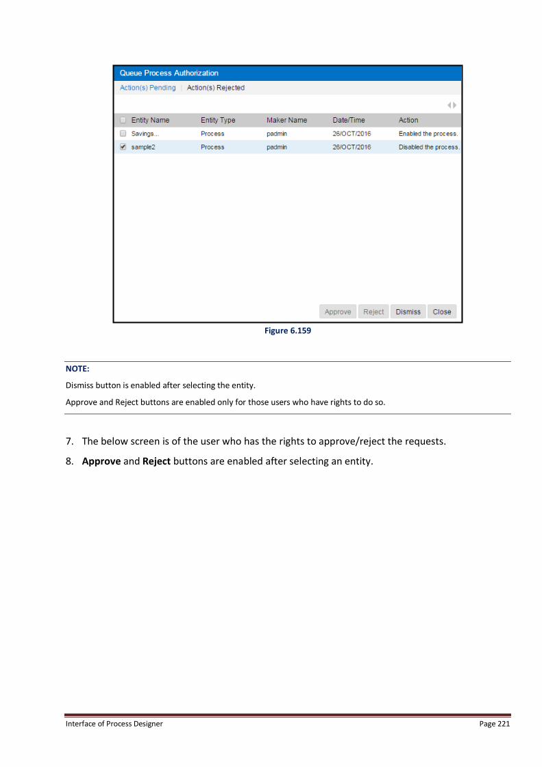
Interface of Process Designer Page 221
Figure 6.159
NOTE:
Dismiss button is enabled after selecting the entity.
Approve and Reject buttons are enabled only for those users who have rights to do so.
7. The below screen is of the user who has the rights to approve/reject the requests.
8. Approve and Reject buttons are enabled after selecting an entity.
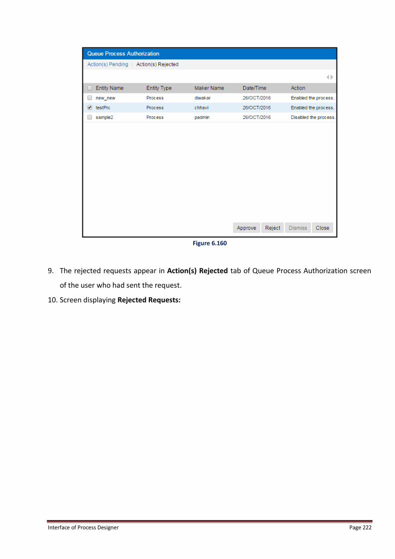
Interface of Process Designer Page 222
Figure 6.160
9. The rejected requests appear in Action(s) Rejected tab of Queue Process Authorization screen
of the user who had sent the request.
10. Screen displaying Rejected Requests:

Interface of Process Designer Page 223
Figure 6.161
11. Screen displayed when no pending and rejected requests are present:
Figure 6.162

Interface of Process Designer Page 224
6.8.4 Form View The Form View option is displayed in Process View menu. Clicking on the Form View directly opens
the Form Builder.
Figure 6.163
Form Builder: For data entry, a customized form can be designed in Form Builder, which is an
integrated component of the iBPS Process Designer and can be imported in the process. Multiple
forms can be designed in a single process and associated with different worksteps.
NOTE:
Please refer to the Form Builder Manual for understanding how to design Forms.
Form Builder
To include the forms for data entry:
1. Click Switch View menu and then click Form View.
2. The Form Builder dialog box is invoked.

Interface of Process Designer Page 225
Figure 6.164
NOTE:
Please refer to the Form Builder Manual for understanding how to design Forms.
Form Updating in registered process:
Process Designer also provides the facility of updating the forms linked to a process directly from
the registered process. The form does not require the check out of the complete process in case it
is required to make changes to the already designed forms.
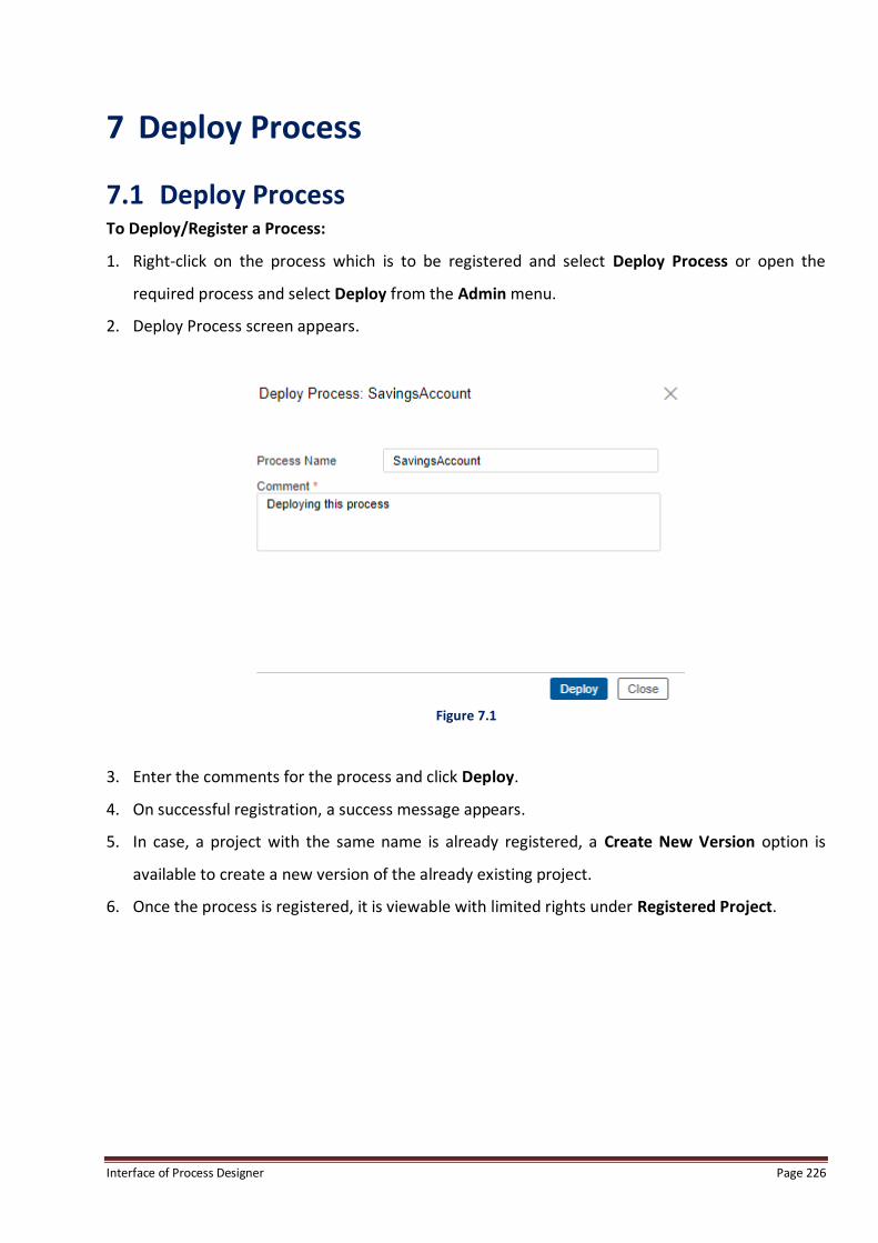
Interface of Process Designer Page 226
7 Deploy Process
7.1 Deploy Process To Deploy/Register a Process:
1. Right-click on the process which is to be registered and select Deploy Process or open the
required process and select Deploy from the Admin menu.
2. Deploy Process screen appears.
Figure 7.1
3. Enter the comments for the process and click Deploy.
4. On successful registration, a success message appears.
5. In case, a project with the same name is already registered, a Create New Version option is
available to create a new version of the already existing project.
6. Once the process is registered, it is viewable with limited rights under Registered Project.

Interface of Process Designer Page 227
7.2 Enable/Disable Process After deploying process, it is mandatory to enable process to create workitems in it and start
working.
Defined Process has two states - ‘Enabled’ or ‘Disabled’. By default, a process is in a disabled state
after it has been registered in the cabinet. The process has to be enabled to allow users to work on
it and workitems to get created in it.
7.2.1 Enable Process Enable Process option is used to make registered process enable in order to start creating
workitems in it.
To Enable a Process:
1. Go to Registered Hierarchy.
2. Select + sign against Registered Project Hierarchy.
3. Select + sign against selected project.
4. Right click on registered process which has to be enabled.
5. Select Enable Process.
Figure 7.2
6. In the comments box that appears, enter comments for enabling the process and click on Ok.
7. System changes icon color from gray to green representing enabled state.
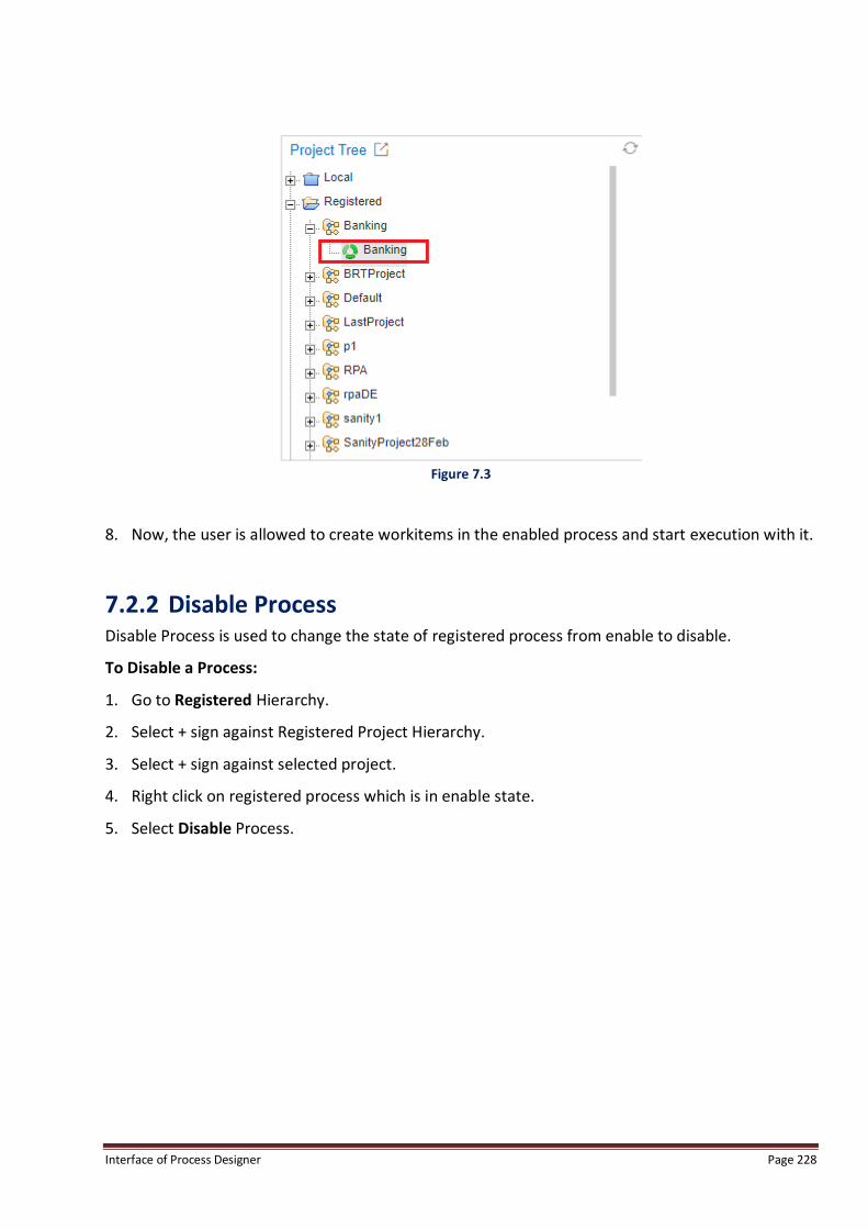
Interface of Process Designer Page 228
Figure 7.3
8. Now, the user is allowed to create workitems in the enabled process and start execution with it.
7.2.2 Disable Process Disable Process is used to change the state of registered process from enable to disable.
To Disable a Process:
1. Go to Registered Hierarchy.
2. Select + sign against Registered Project Hierarchy.
3. Select + sign against selected project.
4. Right click on registered process which is in enable state.
5. Select Disable Process.

Interface of Process Designer Page 229
Figure 7.4
6. In the comments box that appears, enter comment for disabling the process and click on Ok.
7. System changes icon color from green to gray representing disabled state.
Figure 7.5
Interface of Process Designer Page 230
8 Check-in/Check-out Process Process Designer allows user to make changes in registered processes using two options:
Check Out
Save as Local
User has to checkout the registered process if they want to make changes in it. As user selects
Check Out option, the registered process will come under Local Project hierarchy as a new version
of the local process (if it already exists under Local Project Hierarchy) or a new local process (if it
does not exist under Local Project Hierarchy).
After making changes in the process, users have to check in the same process to reflect changes in
the same registered process. As user check in the process, the same changes will be deployed in the
registered process either on the same version or on a new version of the same process (if same
process already exists under Registered Project Hierarchy).
8.1 Check Out This option is used to make changes in the registered process.
Steps to Check out Process (if process with the same name does not exist under Local Project
Hierarchy):
1. Go to Registered Hierarchy.
2. Select + sign against Registered Project Hierarchy.
3. Select + sign against selected project.
4. Right click on the registered process for checkout.
5. Select Check Out.

Interface of Process Designer Page 231
Figure 8.1
6. Check Out Process screen appears.
7. Enter the required comments in Comment textbox.
8. Click Create New Local Copy.
Figure 8.2
NOTE:
If the local process with same name as of registered process exists under Local Project Hierarchy, system displays
Create a New Local Copy button. If the local process with same name as of registered process does not exist under
Local Project Hierarchy, system displays Check Out button.

Interface of Process Designer Page 232
Figure 8.3
9. Click Close to close Check Out Process screen.
10. The Checked out process is now available for modifications in the Local Projects. The registered
business process opens in Modify-mode.
Figure 8.4

Interface of Process Designer Page 233
NOTE:
By default version V 1.0 is created for the process. If user checkout the process with the same name which already
exists under Local Project Hierarchy, new version V 2.0 Is created. User can select any version by selecting Version
Menu from Menu Bar and make changes in the required process. After making changes, user has three options to save
process version: Save as Same Version, Save as Latest Version and Save as Major/Minor Version.
Save as Same Version: This option simply saves the process. The changes are updated on the same
version of the process.
Save as Latest Version: Provides the user with the option of saving any version of the process as
the latest version. For instance, if there are versions 2.0 and 2.1 and we want to save a process as
2.0, it will create a new copy of the same process with version 3.0.
Save as Major Version: Adds +1.0 to the Version No.
Save as Minor Version: Adds +0.1 to the Version No.
Figure 8.5

Interface of Process Designer Page 234
Undo Check out Operation
User can also undo the check out operation performed on processes. Steps to Undo Check out
Operation are as follows:
1. Go to Registered hierarchy.
2. Select + sign against Registered Project Hierarchy.
3. Select + sign against selected project.
4. Right click on Registered Process which has been checked out.
5. Select Undo Check-out.
Figure 8.6
6. Undo-CheckOut Process screen appears.
Figure 8.7
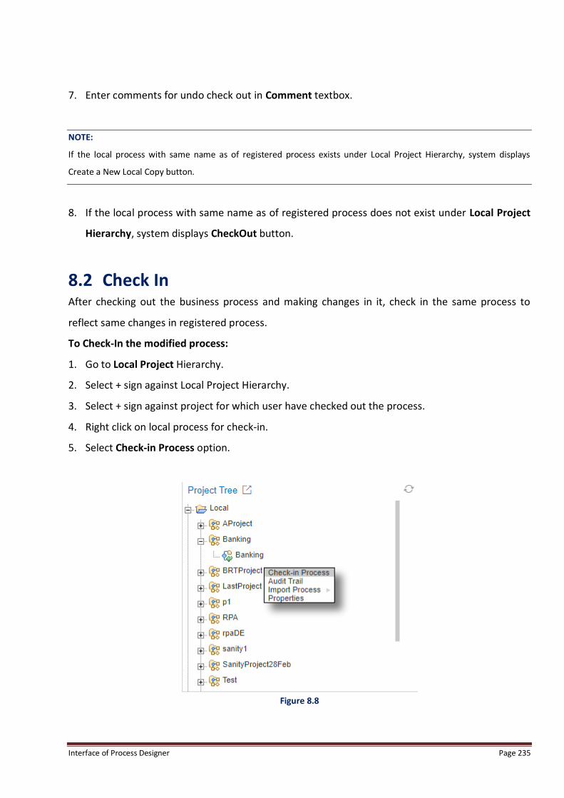
Interface of Process Designer Page 235
7. Enter comments for undo check out in Comment textbox.
NOTE:
If the local process with same name as of registered process exists under Local Project Hierarchy, system displays
Create a New Local Copy button.
8. If the local process with same name as of registered process does not exist under Local Project
Hierarchy, system displays CheckOut button.
8.2 Check In After checking out the business process and making changes in it, check in the same process to
reflect same changes in registered process.
To Check-In the modified process:
1. Go to Local Project Hierarchy.
2. Select + sign against Local Project Hierarchy.
3. Select + sign against project for which user have checked out the process.
4. Right click on local process for check-in.
5. Select Check-in Process option.
Figure 8.8

Interface of Process Designer Page 236
6. Checkin Process screen appears.
7. Enter the comments in Comment textbox.
Figure 8.9
8. Click Overwrite to overwrite the existing registered process or click Create new version to
register a new version.
Figure 8.10
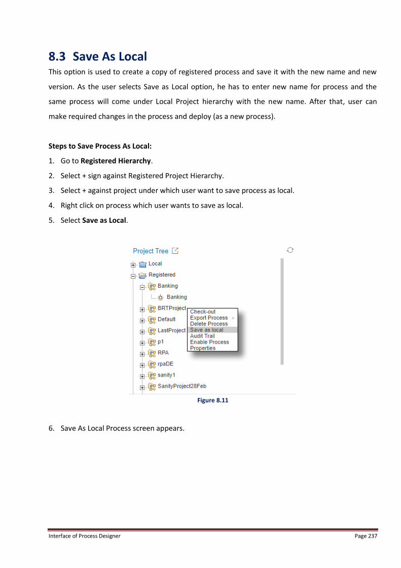
Interface of Process Designer Page 237
8.3 Save As Local This option is used to create a copy of registered process and save it with the new name and new
version. As the user selects Save as Local option, he has to enter new name for process and the
same process will come under Local Project hierarchy with the new name. After that, user can
make required changes in the process and deploy (as a new process).
Steps to Save Process As Local:
1. Go to Registered Hierarchy.
2. Select + sign against Registered Project Hierarchy.
3. Select + against project under which user want to save process as local.
4. Right click on process which user wants to save as local.
5. Select Save as Local.
Figure 8.11
6. Save As Local Process screen appears.

Interface of Process Designer Page 238
Figure 8.12
7. Enter New Process Name and comment for process.
8. Click on Save button.
9. The following message appears.
Figure 8.13
10. Click Close to close the screen.
11. The saved process is displayed under Local hierarchy.
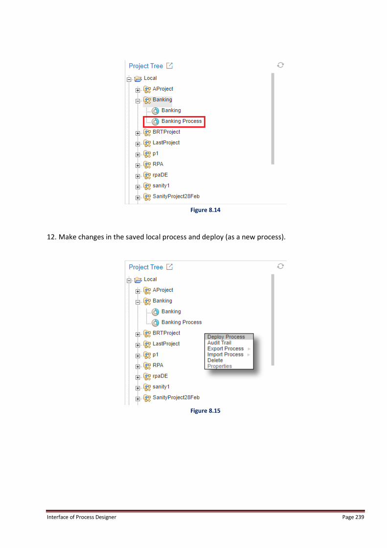
Interface of Process Designer Page 239
Figure 8.14
12. Make changes in the saved local process and deploy (as a new process).
Figure 8.15

Interface of Process Designer Page 240
9 Export Process from Registered Process Export Process functionality in Registered Repository is used to export an existing registered
process from one server to another. The Export Process option is used if a process created on one
server by a particular user is to be used by a user on a different server. A zip file of the process can
be sent to the other user.
User needs to right click on the registered process and select Export Process. User is able to export
process in XML, XPDL 2.2 and BPMN 2.0.
Figure 9.1
As user select XML, XPDL 2.2 or BPMN 2.0, the following screen appears:
Figure 9.2
Click Close to close Export Process dialog box once the process has downloaded/exported.

Interface of Process Designer Page 241
10 Import/Export Process from Local Process
10.1 Import Process Process Designer supports XML and BPEL (Business Process Execution Language) formats to import
processes in project.
XML: This is Newgen specific file format i.e. user is able to import processes which have been
previously exported from Newgen process designer. System does not support XML format
processes from external process designers.
BPEL, XPDL 2.2, BPMN 2.0: These are standard formats that the system supports importing
processes from external or Newgen process designer.
NOTE:
User cannot import any process, created in previous versions of ibps 3.0-SP1, without making any manual changes in
them.
1. Right click on the project in which a process is to be imported.
2. Process in XML or BPEL format can be imported.
3. Click on Import Process and select XML/BPEL.
Figure 10.1
4. Import Process screen appears.
5. Click on Choose File and select the process file.

Interface of Process Designer Page 242
6. Click on Import Process.
Figure 10.2
7. Process imported successfully message appears on successful import of the process.
8. Click on Close to close the message box.
Figure 10.3
9. If the user right clicks on a process name and select import process, the following window
opens. This is used to overwrite the selected process in the project.

Interface of Process Designer Page 243
Figure 10.4
10. Click on Choose File to locate and select the process.
11. Click on Create New Version to create a new version or select Overwrite to overwrite the
existing process with the process selected for import.
NOTE:
1. If process is imported in BPMN/XPDL, only process’s workflow is imported. Properties are allowed to import from
Newgen XML format.
2. Query workstep is Newgen proprietary and not in the specifications of BPMN/XPDL. So if process with Query
workstep is imported in BPMN/XPDL, it is imported as Newgen's workdesk and behaves like a standard workdesk
which needs incoming and outgoing connections.
3. System allows user to import only two BPEL processes as of now:
NgInsuranceClaim
NgPurchaseOrder
(Refer product team for process definitions).
10.2 Export Process Export Process is used to export an existing process from one server to another. The Export Process
option is used if a process created on one server by a particular user is to be used by a user on a
different server. A zip file of the process can be sent to the other user.
User needs to right click on process and select Export Process. User is able to export process in
XML, XPDL 2.2, BPMN 2.0 and BPEL.

Interface of Process Designer Page 244
Figure 10.5
The user can import the same process on his server using the exported zipped folder.
The file can be saved onto the user’s local system and be used later.
NOTE:
1. If process is exported in BPMN/XPDL, only process’s workflow is exported. Properties are allowed to export from
Newgen XML format only.
2. Query workstep is Newgen proprietary and not in the specifications of BPMN/XPDL. So if process with Query
workstep is exported in BPMN/XPDL, it is exported as Newgen's workdesk and behaves like a standard workdesk
which needs incoming and outgoing connections.
3. System does not allow user to export registered and checked out processes. As user exports the
registered/checked out process, system gives alert message.
User is allowed to export local processes only. If user wants to export registered processes, he has
to right click on selected Registered Process; select “Save as Local” option and save process with a
new name. Now user is able to export the selected process.
NOTE:
It is recommended to export BPEL compliant processes only.

Interface of Process Designer Page 245
11 Delete Project/Process
11.1 Delete Project When a particular project is deleted, all the processes within that project along with their versions
are also removed.
To delete an existing local project:
1. Select + sign against Local Project Hierarchy.
2. Right click on project which user wants to delete and Select Delete.
Figure 11.1
3. System displays Confirm Dialog Box.
Figure 11.2
4. Clicking on ‘Yes’ removes the project and all the processes within it.
5. Clicking on ‘No’ cancels the delete operation.
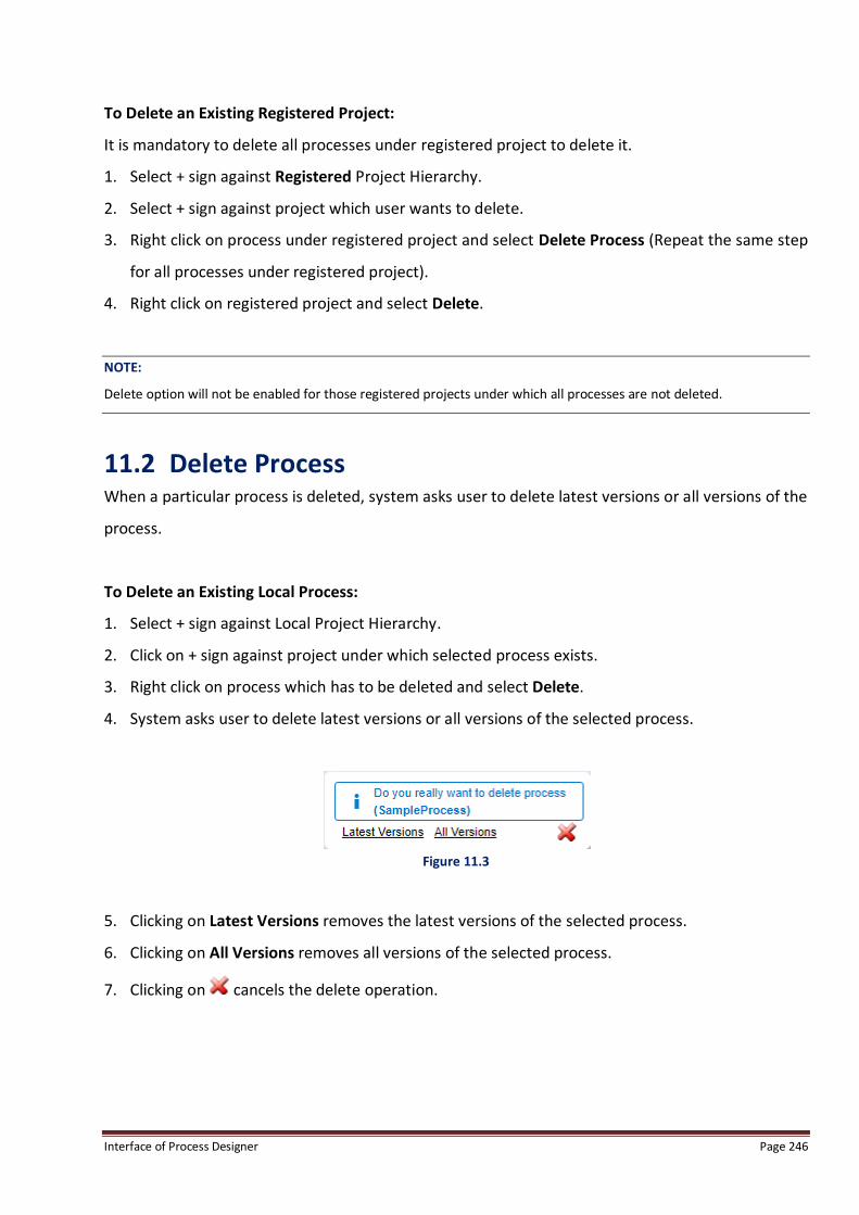
Interface of Process Designer Page 246
To Delete an Existing Registered Project:
It is mandatory to delete all processes under registered project to delete it.
1. Select + sign against Registered Project Hierarchy.
2. Select + sign against project which user wants to delete.
3. Right click on process under registered project and select Delete Process (Repeat the same step
for all processes under registered project).
4. Right click on registered project and select Delete.
NOTE:
Delete option will not be enabled for those registered projects under which all processes are not deleted.
11.2 Delete Process When a particular process is deleted, system asks user to delete latest versions or all versions of the
process.
To Delete an Existing Local Process:
1. Select + sign against Local Project Hierarchy.
2. Click on + sign against project under which selected process exists.
3. Right click on process which has to be deleted and select Delete.
4. System asks user to delete latest versions or all versions of the selected process.
Figure 11.3
5. Clicking on Latest Versions removes the latest versions of the selected process.
6. Clicking on All Versions removes all versions of the selected process.
7. Clicking on cancels the delete operation.
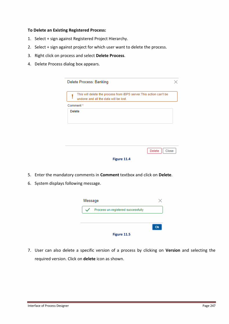
Interface of Process Designer Page 247
To Delete an Existing Registered Process:
1. Select + sign against Registered Project Hierarchy.
2. Select + sign against project for which user want to delete the process.
3. Right click on process and select Delete Process.
4. Delete Process dialog box appears.
Figure 11.4
5. Enter the mandatory comments in Comment textbox and click on Delete.
6. System displays following message.
Figure 11.5
7. User can also delete a specific version of a process by clicking on Version and selecting the
required version. Click on delete icon as shown.

Interface of Process Designer Page 248
Figure 11.6
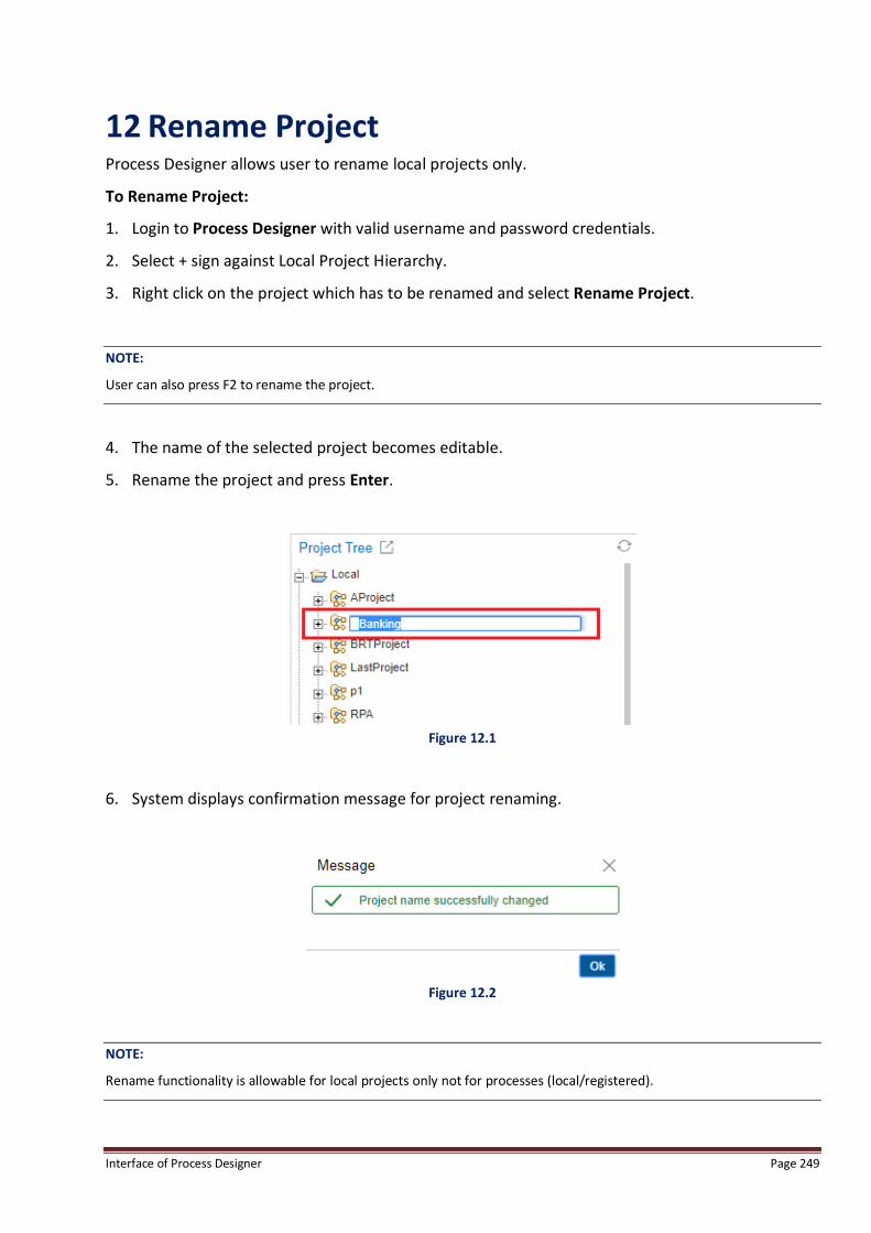
Interface of Process Designer Page 249
12 Rename Project Process Designer allows user to rename local projects only.
To Rename Project:
1. Login to Process Designer with valid username and password credentials.
2. Select + sign against Local Project Hierarchy.
3. Right click on the project which has to be renamed and select Rename Project.
NOTE:
User can also press F2 to rename the project.
4. The name of the selected project becomes editable.
5. Rename the project and press Enter.
Figure 12.1
6. System displays confirmation message for project renaming.
Figure 12.2
NOTE:
Rename functionality is allowable for local projects only not for processes (local/registered).
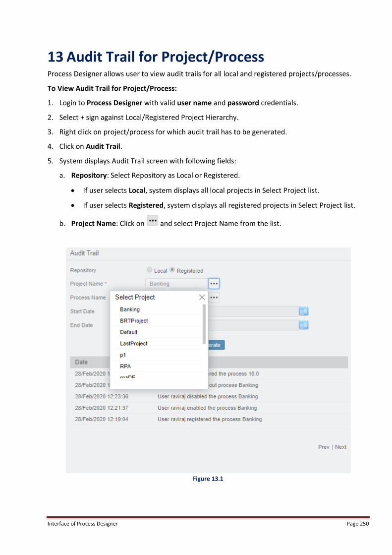
Interface of Process Designer Page 250
13 Audit Trail for Project/Process Process Designer allows user to view audit trails for all local and registered projects/processes.
To View Audit Trail for Project/Process:
1. Login to Process Designer with valid user name and password credentials.
2. Select + sign against Local/Registered Project Hierarchy.
3. Right click on project/process for which audit trail has to be generated.
4. Click on Audit Trail.
5. System displays Audit Trail screen with following fields:
a. Repository: Select Repository as Local or Registered.
If user selects Local, system displays all local projects in Select Project list.
If user selects Registered, system displays all registered projects in Select Project list.
b. Project Name: Click on and select Project Name from the list.
Figure 13.1

Interface of Process Designer Page 251
c. Process Name: Click on and select Process Name from the list.
As user select Repository as Local and project name, system displays all local processes
of the selected project.
As user select Repository as Registered and project name, system displays all registered
processes of the selected project.
User can also select all processes under selected project simultaneously using ALL
option.
d. Start Date: Select Start Date from which the audit trail has to be generated.
e. End Date: Select End Date to which the audit trail has to be generated.
6. Click on Generate button. System displays Date and Description fields displaying activities
performed on projects/processes within selected date range.
Figure 13.2
NOTE:
User can view audit trail at both project and process levels.

Interface of Process Designer Page 252
14 Collaborative Process
14.1 Share Process This option is used to share the current process with all the users on a particular server. Every user
is able to view a particular process created by a particular process.
To share the particular process with users:
1. Open the process which has to be shared.
2. Click on Share option from the menu bar.
3. Select User dialog box appears.
Figure 14.1
4. Select users from the users list. A process can be shared with multiple users at a time.
5. Click OK to send the sharing request to the selected users and the screen of the owner user
changes to shared screen.
6. Selected user(s) receives a notification request of the process shared.

Interface of Process Designer Page 253
Figure 14.2
7. Clicking on the Notification Link opens the complete message, as shown below.
Figure 14.3
8. Requested user can either accept the request by clicking Ok, or reject the request by clicking
Cancel.
9. If accepted, the screen is changed to shared mode and the shared process opens.

Interface of Process Designer Page 254
Figure 14.4
10. If the user rejects the share request, owner of the process gets a notification for rejection of
sharing request by the respective user.
Figure 14.5
11. When share request is accepted by the user, owner of the process receives notification of
acceptance of the request by the users.
Figure 14.6
12. The screen of both the Owner of process and the requested user are same and owner can make
desired changes that are reflected on the screen of shared users.
NOTE:
Only one user can make changes at a time.

Interface of Process Designer Page 255
14.2 Unshare Process Once the process is shared by the users, owner of the process can unshare the process at any time.
To Unshare the Process:
1. Click on Unshare.
Figure 14.7
2. The process is unshared from all the users with whom the process was shared and the owner’s
screen returns to normal BPMN view.
3. When the owner unshare a process, a notification of unshare is sent to all the users with whom
process was previously shared and the normal view is restored for the users.
Figure 14.8
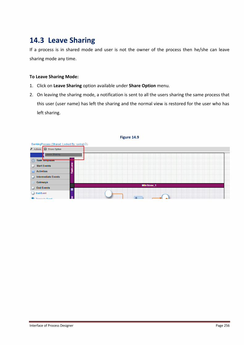
Interface of Process Designer Page 256
14.3 Leave Sharing If a process is in shared mode and user is not the owner of the process then he/she can leave
sharing mode any time.
To Leave Sharing Mode:
1. Click on Leave Sharing option available under Share Option menu.
2. On leaving the sharing mode, a notification is sent to all the users sharing the same process that
this user (user name) has left the sharing and the normal view is restored for the user who has
left sharing.
Figure 14.9

Interface of Process Designer Page 257
14.4 Request Lock If any users, with whom the process is shared, want to modify process, they have to send a request
to the owner to grant lock (Request Lock) on the process so that they can make modifications to
the process. Request Lock option is available on right click of swimlane or an activity.
Figure 14.10
On requesting lock, a request to get lock on process is sent to the owner of the process. He can
either accept (by clicking Ok) or reject (by clicking Cancel).
Figure 14.11
In case the owner cancels the Request Lock request of the user. A notification is sent to the
respective user for deny of the lock request.
Figure 14.12

Interface of Process Designer Page 258
If owner accepts lock requested by the user, the screen of the owner changes to viewer mode
(where he cannot make changes in the process). In Viewer mode he can only observe the changes
done by other user, chat with the users or revoke lock.
On acceptance of lock request by the owner, a notification is send to the user to whom lock has
been granted and the view of the user is now editable, i.e. the user can make changes to the
process. The user can add worksteps connect them and change the properties of worksteps
respectively. The changes made by the user (with lock) are reflected to the screens of other users at
the same time.
The changes made by the user are denoted by any particular color of lines and dots on the
worksteps. For example, the worksteps connected by black lines are created by the owner itself.
Whereas, worksteps, on whom green dot is present, and which are connected by green lines are
made by the user to whom temporary rights are given.

Interface of Process Designer Page 259
14.5 Grant Lock Owner of the process can also grant lock to other user to whom he wishes to. Grant Lock option is
available by right clicking on the BPMN View.
Figure 14.13
On click of Grant Lock, a list of users among whom the process is shared, is populated and the
owner can select a user and send a grant lock request to the selected user.

Interface of Process Designer Page 260
Figure 14.14
Once the owner grants lock to the selected user, the screen of the owner changes to observer
mode (where he can only view the changes made in the process).
Figure 14.15

Interface of Process Designer Page 261
The user to whom the lock is granted gets a notification and his screen changes to the Editable
Mode(where he can make changes in the shared process).
Figure 14.16
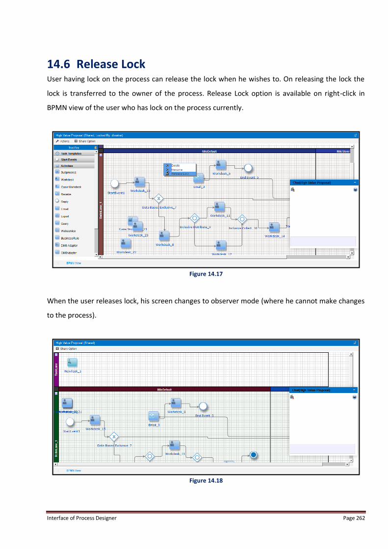
Interface of Process Designer Page 262
14.6 Release Lock User having lock on the process can release the lock when he wishes to. On releasing the lock the
lock is transferred to the owner of the process. Release Lock option is available on right-click in
BPMN view of the user who has lock on the process currently.
Figure 14.17
When the user releases lock, his screen changes to observer mode (where he cannot make changes
to the process).
Figure 14.18

Interface of Process Designer Page 263
On release of lock a notification is sent to the owner of the process and the lock (control) is also
transferred to the owner.
Figure 14.19

Interface of Process Designer Page 264
14.7 Revoke Lock If lock is granted to other user, the owner of the process can get control back by 'Revoke Lock'
option. Revoke Lock option is available on right click in BPMN view of the owner when lock is
granted to other user.
Figure 14.20
On revoking lock, a notification is sent to the user who was holding the lock and his screen changes
to observer mode.
Figure 14.21

Interface of Process Designer Page 265
14.8 Chat Users sharing the process can also communicate to each other via chat instance available in the
sharing mode. Chat is a group chat and is broadcasted to all the users currently sharing the process.
Figure 14.22
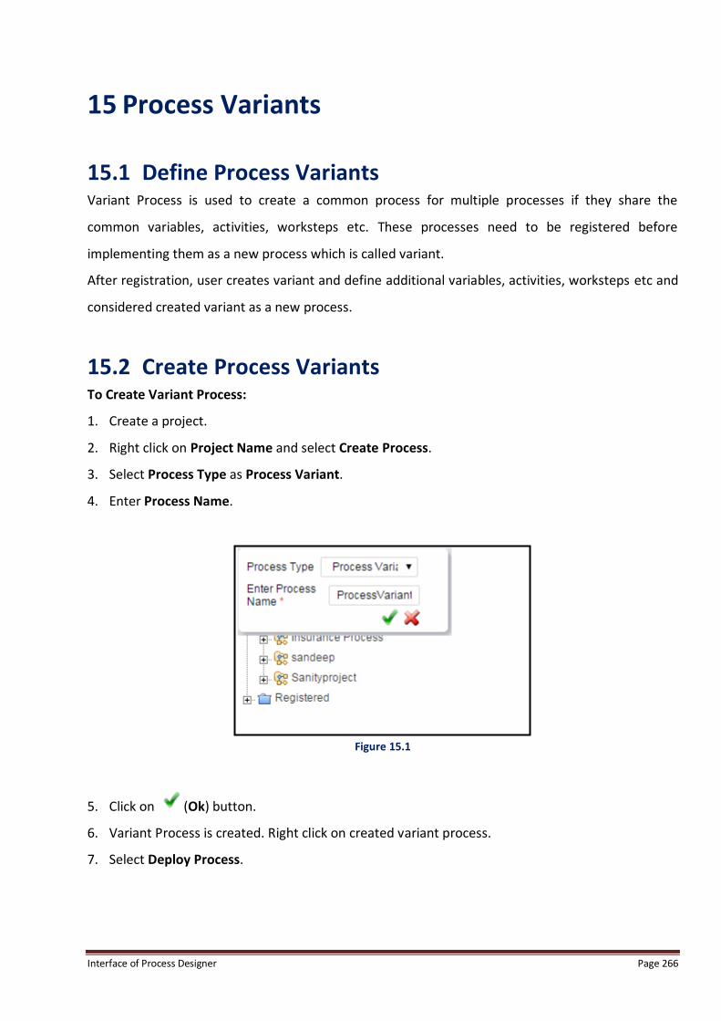
Interface of Process Designer Page 266
15 Process Variants
15.1 Define Process Variants Variant Process is used to create a common process for multiple processes if they share the
common variables, activities, worksteps etc. These processes need to be registered before
implementing them as a new process which is called variant.
After registration, user creates variant and define additional variables, activities, worksteps etc and
considered created variant as a new process.
15.2 Create Process Variants To Create Variant Process:
1. Create a project.
2. Right click on Project Name and select Create Process.
3. Select Process Type as Process Variant.
4. Enter Process Name.
Figure 15.1
5. Click on (Ok) button.
6. Variant Process is created. Right click on created variant process.
7. Select Deploy Process.

Interface of Process Designer Page 267
Figure 15.2
8. Deploy Process screen appears.
9. Enter the mandatory comments required for deployment.
Figure 15.3
10. Click on Deploy.
11. A message for successful deployment appears in Deploy Process screen.

Interface of Process Designer Page 268
Figure 15.4
12. Click Close to close Deploy Process screen.
13. The deployed variant process comes under Registered heading in Project Tree.
14. Variant Process is different from Generic Process in respect of following sections:
a. Tools - System displays limited features in Tools Tab including:
Document(s)
Catalog Definition
Trigger
Register Template
Process Report
Property Association
Default Queues for Activity
b. Options– System displays limited features in Options Tab including:
Constants
Queue Variables
Search Variables
Define Variable Alias
c. Process View - System displays limited features in Process View section including:
Business Variables

Interface of Process Designer Page 269
Figure 15.5
d. Properties View - System displays limited features in Properties View section including:
Process
Requirements
Attachments
15.3 Add Variants To Create Variants:
Right click on registered variant process and select Create Variant. System displays Create Process
Variant form with Variant Process Name.
15.3.1 Registration Registration Tab is used to register the variant process by entering following fields:
Variant Name – Enter variant name.
Variant Code – Enter variant code.
Prefix – Displays prefix for variant process.
Starting Sequence No. – Displays the starting sequence number.
Suffix – Displays the suffix for variant process.
Registration Length –This is read-only field and defines the registration length.

Interface of Process Designer Page 270
Figure 15.6
15.3.2 Variable(s) Variable(s) Tab is used to add variables with the registered variant process.
Figure 15.7
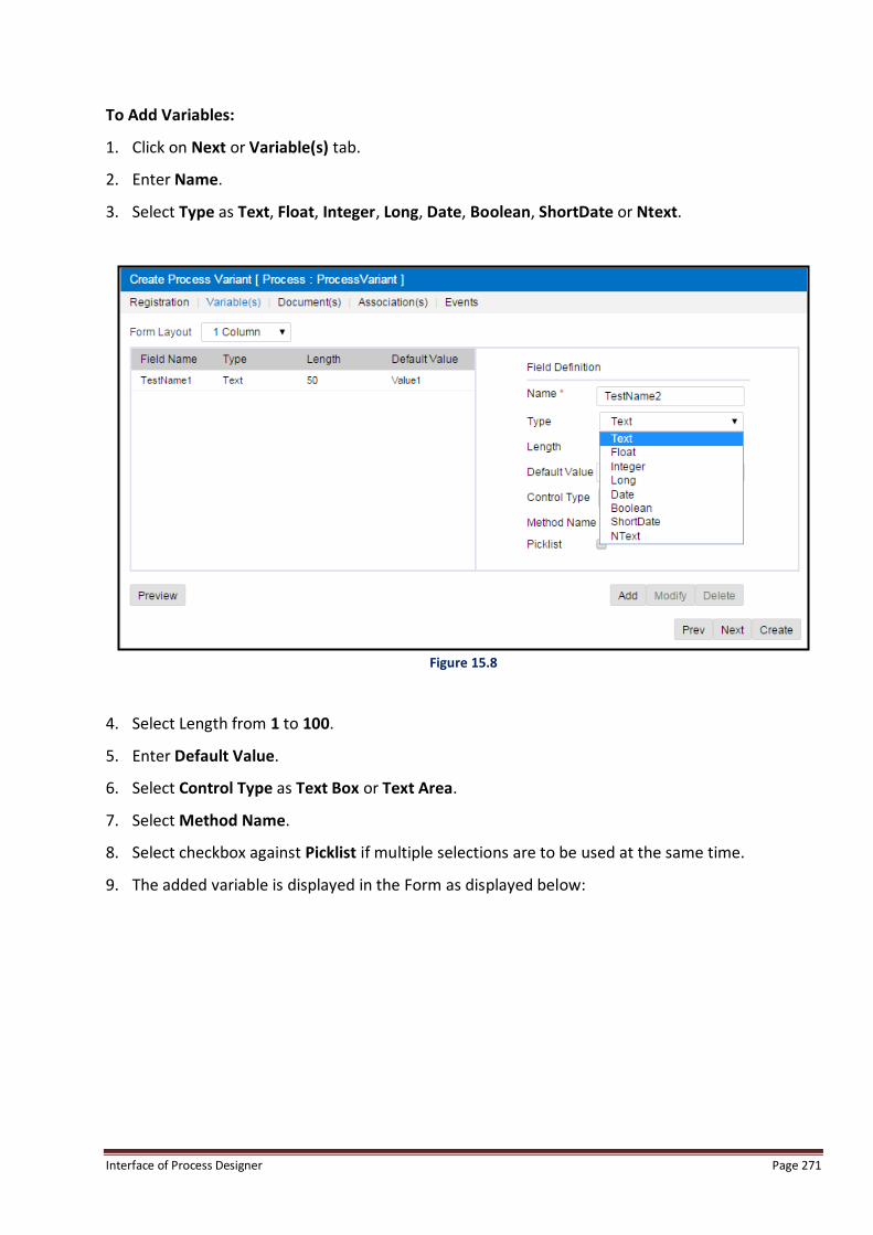
Interface of Process Designer Page 271
To Add Variables:
1. Click on Next or Variable(s) tab.
2. Enter Name.
3. Select Type as Text, Float, Integer, Long, Date, Boolean, ShortDate or Ntext.
Figure 15.8
4. Select Length from 1 to 100.
5. Enter Default Value.
6. Select Control Type as Text Box or Text Area.
7. Select Method Name.
8. Select checkbox against Picklist if multiple selections are to be used at the same time.
9. The added variable is displayed in the Form as displayed below:
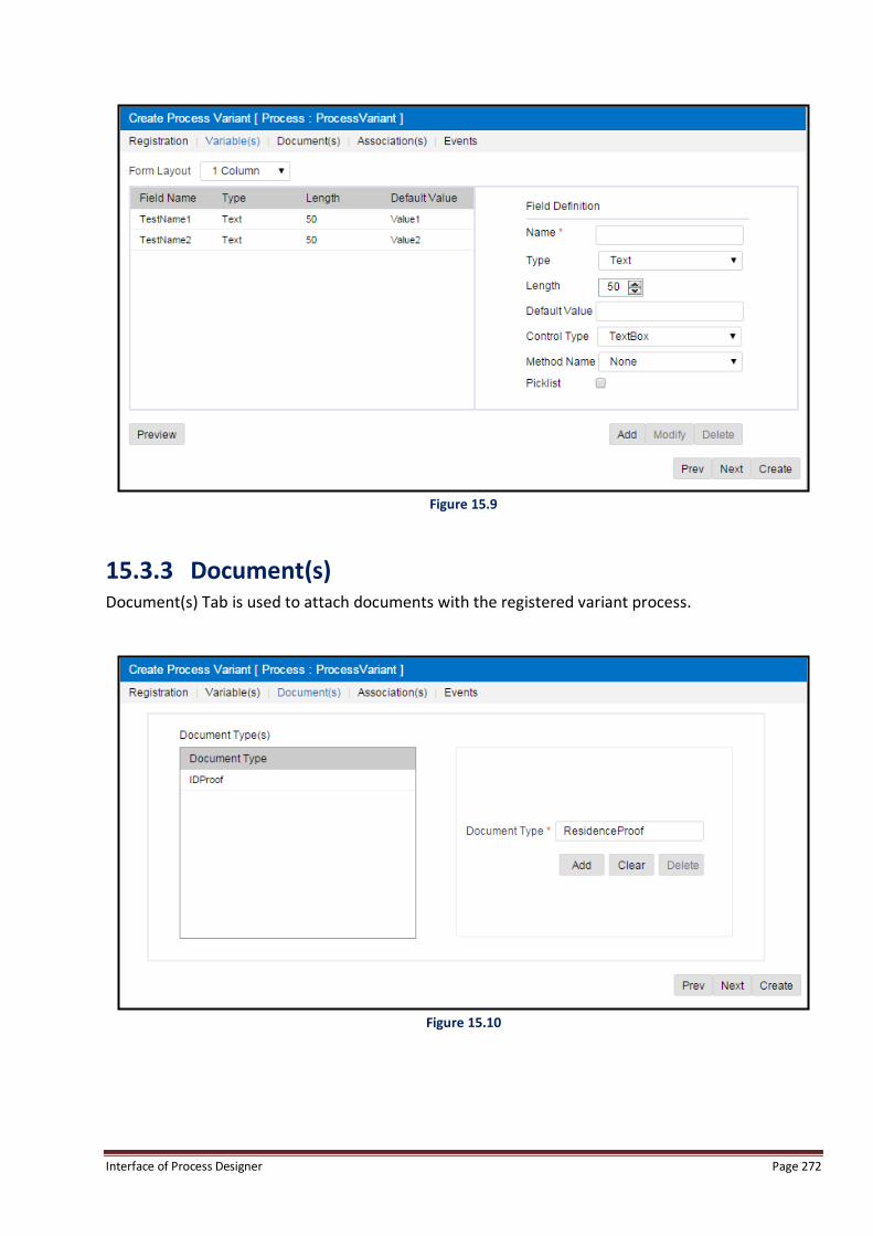
Interface of Process Designer Page 272
Figure 15.9
15.3.3 Document(s) Document(s) Tab is used to attach documents with the registered variant process.
Figure 15.10

Interface of Process Designer Page 273
To Add Document in Variant Process:
1. Click on Next or Document(s) tab.
2. Enter the type of document in Document Type textbox.
3. Click on Add to add the document type which has to be uploaded at the execution time.
4. To delete added document type:
Select the document type listed in Document Type.
Click on Delete. The deleted document type is removed from Document Type list.
15.3.4 Association(s) Association(s) Tab is used to associate rights for activities and data variables with the registered
variant process.
Association is used to define at which level user wants to display, edit and hide additional variables
by selecting checkboxes against them.
Display – Displays selected field on execution.
Editable – Allows user to edit variable on execution.
Hidden – Hides the selected variable at runtime.
Mandatory – Make the selected variable mandatory.
Steps to associate rights:
1. Select checkboxes against Enable/Editable/Hidden/Mandatory.
2. Click Apply.
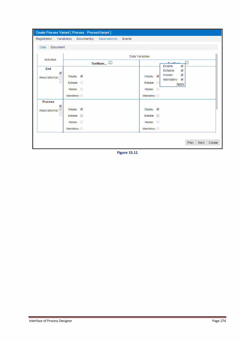
Interface of Process Designer Page 274
Figure 15.11

Interface of Process Designer Page 275
15.3.5 Events Event(s) Tab is used to add events for the registered variant process. Events are used to add new
functions or use existing functions on three execution modes OnChange, OnLoad and OnSave
written in JavaScript.
Figure 15.12
To Add Events:
1. Click on New button.
2. Select Execution Mode.
3. Enter Function Name.
4. Enter Function Code.
5. Click on Save button.
Sample Code for Adding Components on Form
var formDivId = getInterfaceKey("form");
var formObj = null;
if(formDivId != null){

Interface of Process Designer Page 276
formObj = document.getElementById(formDivId);
if(formObj != null){
var inputButton = document.createElement("INPUT") ;
inputButton.setAttribute("type","button");
inputButton.setAttribute("id","customIB1");
inputButton.setAttribute("value","Value");
inputButton.className="EWButton";
inputButton.style.position = "absolute";
inputButton.style.bottom = "0px";
inputButton.style.left = "0px";
inputButton.onclick = function (){
alert("qInt1: "+ document.getElementById("wdesk:qInt1").value)
return false;
}
formObj.appendChild(inputButton);
inputButton = document.createElement("INPUT") ;
inputButton.setAttribute("type","button");
inputButton.setAttribute("id","customIB2");
inputButton.setAttribute("value","Save");
inputButton.className="EWButton";
inputButton.style.position = "absolute";
inputButton.style.bottom = "0px";
inputButton.style.left = "60px";
inputButton.onclick = function (){
mainSave();
return false;
}
formObj.appendChild(inputButton);
inputButton = document.createElement("INPUT") ;
inputButton.setAttribute("type","button");
inputButton.setAttribute("id","customIB3");
inputButton.setAttribute("value","introduceWI");
inputButton.className="EWButton";
inputButton.style.position = "absolute";

Interface of Process Designer Page 277
inputButton.style.bottom = "0px";
inputButton.style.left = "120px";
inputButton.onclick = function (){
introduceWI();
return false;
}
formObj.appendChild(inputButton);
}
}
15.4 Modify Variants To Modify Variants:
Right click on Variant name and select Modify Variant.
NOTE:
User checked out the base process, adds new variables in it, and checked in the same base process, it is mandatory to
open all variant definitions related to that base process and click on Update button.
15.4.1 Registration User is not able to modify the registration details since it is one time entry.
Figure 15.13
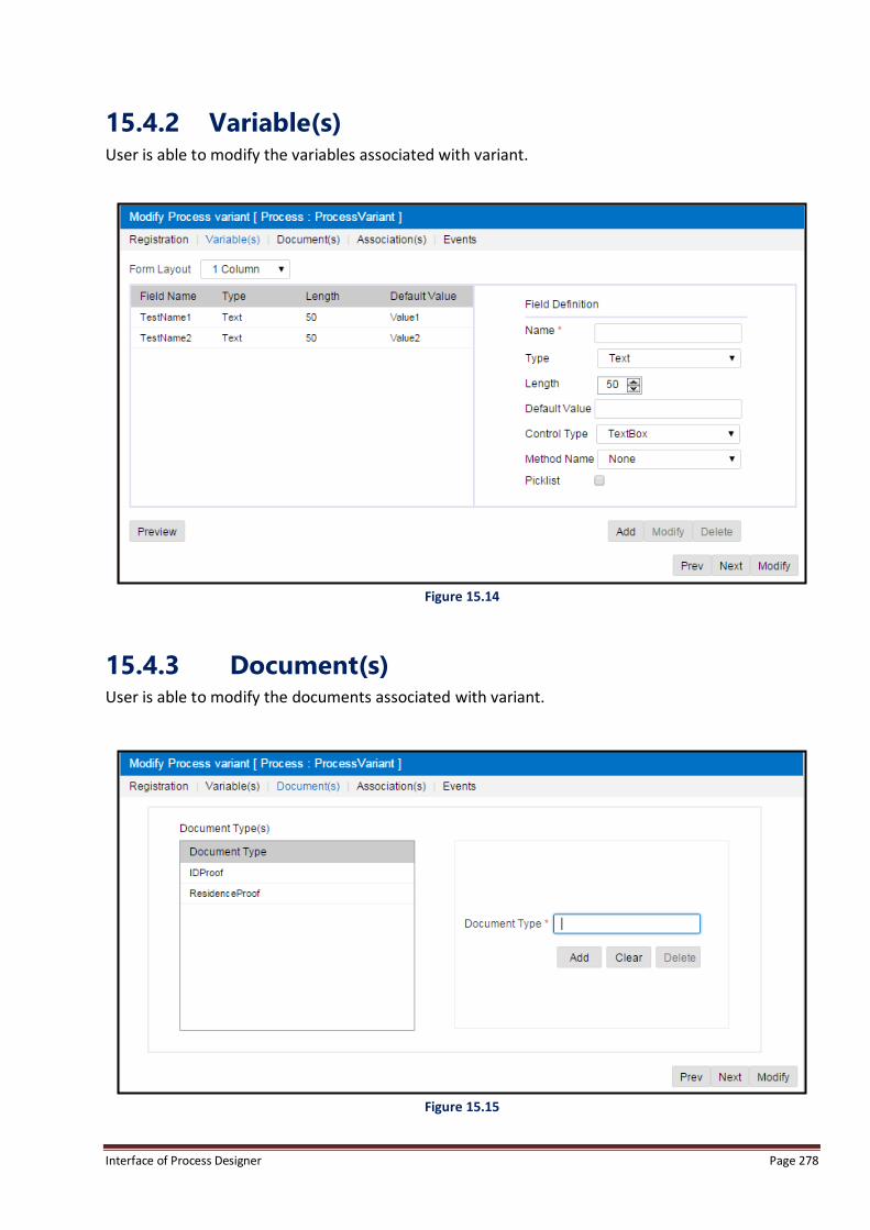
Interface of Process Designer Page 278
15.4.2 Variable(s) User is able to modify the variables associated with variant.
Figure 15.14
15.4.3 Document(s) User is able to modify the documents associated with variant.
Figure 15.15

Interface of Process Designer Page 279
15.4.4 Association(s) User is able to modify the associations linked with variant.
Figure 15.16

Interface of Process Designer Page 280
15.4.5 Events User is able to modify the events associated with variant.
Figure 15.17

Interface of Process Designer Page 281
15.5 Delete Variants To Delete Variants:
1. Right click on the Variant which has to be deleted and select Delete Variant.
2. As user selects Delete Variant, system deletes the variant from the database and does not
display the deleted variant on GUI.
15.6 Enable Variants To Enable Variants:
1. Right click on Variant which has to be enabled and select Enable Variant.
2. As user selects Enable Variant, system enables the variant i.e. variant is ready for execution. By
default variant is disable, so if user wants to execute variant, he has to enable the variant.
15.7 Audit Trail To View Audit Trail:
1. Right click on Variant Process Name and select Audit Trail.
2. As the user selects Audit Trail, system opens Audit Trail form as shown below:
Figure 15.18

Interface of Process Designer Page 282
16 List of Abbreviations BPEL: Business Process Execution Language
BPM: Business Process Model
BPMN: Business Process Model and Notation
BRT: Business Rule Task
CC: Carbon Copy
DMS: Document Management System
GUI: Graphical User Interface
HTTP: Hyper Text Transfer Protocol
HTTPS: Hyper Text Transfer Protocol Secure
iBPS: Intelligent Business Process Suite
IP: Internet Protocol
JMS: Java Message Service
LHS: Left Hand Side
OTMS: Omni Transport Management System
SAP: Systems, Applications and Products
SOAP: Simple Object Access Protocol
URL: Uniform Resource Locator
WSDL: Web Services Description Language
XML: Extensible Markup Language
XPDL: XML Process Definition Language