Embed Size (px)
Citation preview

it II
• • • •
PROCESS DESIGN REPORT FOR WASTEWATER TREATMENT
PLANT UPGRADE
Prepared for
Western Refining Southwest
Gallup Refinery
BROWN AND
CAL D WE L_L
L 11 1· 1 r o u n1 c 11 r a I F 11 g 1 11 c c r-' c·· Co n .i u I r ri u 1 _,

II II
... lllilll
-.. --!!IIIII -!!IIIII
lllilll
1!11111 .. """ -.. --... IIIII
• -• .. ... .. • -.. """ .. IIIII -111111111 --.. IIIII ..
LIBRARV' COPY WWestern
PROCESS DESIGN REPORT FOR WASTEWATER TREATMENT
PLANT UPGRADE
Prepared for Western Refining Southwest
Gallup Refinery
February 26, 2009
Submitted to: New Mexico Oil Conservation Division
Environmental Bureau Santa Fe, New Mexico
p db • BROWN AND CALDWELL
30 East Seventh Street, Suite 2500
Saint Paul, MN 55101

llil
--111111 -111111 -111111 ..
B R f) \\ \ I \ ll .. C \ L n \\ l L L ;
-111111
-----IIIII -!IIIII --.. 1!11111111 -!IIIII
---IIIII
-IIIII ---!IIIII -IIIII -
30 East Seventh Street Suite 2500 Saint Paul, MN 55101
Tel: 651-298-0710 Fax: 651-298-1931
www.brownandcaldwcll.com
February 26, 2009
Mr. Ed Riege Western Refining Southwest Gallup Refinery Route 3, Box 7 Gallup, NM 87301
Subject: Transmittal of Process Design Report
Dear Mr. Riege:
135741.021.300
Brown and Caldwell is pleased to provide the attached Process Design Report to Western Refining Southwest for the upgrades to the wastewater treatment plant (WWTP) at the Gallup Refinery.
Brown and Caldwell appreciates the opportunity to work with Western Refining on the design of the WWTP upgrades. If you have any questions on this report, please contact me at (651) 468-2061 or [email protected].
Very truly yours,
BROWN AND CALDWELL
Jeffrey S. A en, P.E. Project Manager New Mexico Registration No. 18988
E fl l' i r o 11 lJI e 11 I a I E 11 .~ i 11 e e r .r
L022609Rie.doc
& Con.rultant

IIi I
------IIIII
---IIIII -----IIIII -Mil ---IIIII ---... --.. --------
Professional Engineer Certification for JeffreyS. Allen, P.E.
This is to certify that the Process Design Report for Western Reftning Southwest dated February 2009 was prepared under my direction and supervision. The exception to this certiftcation is the material in Attachment C.
License No. 18988 February 26, 2009

fl
-.... --- TABLE OF CONTENTS - 1. INTRODUCTION .................................................................................................................................................... 1-1
- 1.1 Introduction ..................................................................................................................................................... 1-1 1.2 Project Scope ................................................................................................................................................. 1-1 - 1.3 Related Project- Pilot Travel Center Lift Station ........................................................................................... 1-2 - 1.4 Treatment Objectives ..................................................................................................................................... 1-2 - 1.5 Regulatory Compliance .................................................................................................................................. 1-2 1.6 Report Organization ....................................................................................................................................... 1-2 - 2. WASTEWATER SOURCES ................................................................................................................................... 2-1 - 2.1 Overview ........................................................................................................................................................ 2-1 - 2.2 Refinery Wastewaters .................................................................................................................................... 2-1 2.3 Pilot Travel Center Wastewaters .................................................................................................................... 2-1 - 2.4 Design Flow .................................................................................................................................................... 2-2 - 3. TECHNOLOGY SELECTION ................................................................................................................................. 3-1
IIIII 3.1 Overview ........................................................................................................................................................ 3-1 - 3.2 Second-Stage Oil-Water Separation .............................................................................................................. 3-1 3.3 Biological Treatment ....................................................................................................................................... 3-2 - 4. PROCESS DESCRIPTION ................................................................................................................................... .4-1 - 4.1 Overview ....................................................................................................................................................... .4-1 - 4.2 New System .................................................................................................................................................. .4-1
4.2.1 Stormwater/Diversion Tanks .............................................................................................................. .4-1 - 4.2.2 NAP IS Effluent Pumping .................................................................................................................... .4-1 IIIII 4.2.3 NAP IS Effluent pH Control ................................................................................................................. .4-2
- 4.2.4 Tank-Based Seprator ......................................................................................................................... A-2 4.2.5 Bioreactors ......................................................................................................................................... .4-2 - 4.2.6 Evaporation Pond No. 1 ..................................................................................................................... .4-4 - 4.2.7 Chemical Feed Systems ..................................................................................................................... 4-4
- 4.2.8 WWTP Operations Building ............................................................................................................... .4-4 4.3 Decommissioned Systems ............................................................................................................................ .4-4 - 4.3.1 Benzene Strippers Nos. 1 , 2 and 3 .................................................................................................... .4-4 - 4.3.2 AL-1 and AL-2 .................................................................................................................................... .4-5
4.3.3 OAPIS ................................................................................................................................................ .4-5 - 4.4 Management of Off-Spec Wastewater .......................................................................................................... .4-5 - 4.5 Secondary Containment and Leak Detection ................................................................................................ .4-5
- 4.6 Alternative Upgrade Approach ...................................................................................................................... .4-6
- 5. PROJECT SCHEDULE .......................................................................................................................................... 5-1
-.. ----

IIi I
,.... .. -----.. -• ---.. -----... ------------------
LIST OF ATTACHMENTS
ATTACHMENT A: PROCESS FLOW DIAGRAMS
ATTACHMENT B: PRELIMINARY SITE PLAN
ATTACHMENT C: STORMWATER/DIVERSION TANK DRAWINGS
ATTACHMENT D: TECHNICAL PAPER ON TANK-BASED SEPARATOR CASE STUDIES
ATTACHMENT E: MEMBRANE BIOREACTOR PILOT STUDY
ATTACHMENT F: AGGRESSIVE BIOLOGICAL TREATMENT CALCULATIONS
LIST OF TABLES
Table 2-1 Design Flow Rates ............................................................................................................................... 2-2 Table 5-1 Estimate of Project Schedule Through Construction ............................................................................ 5-1

Pi I
ll"l -----.. .. .. .. .. ---.. -illl!ll' --fC:
---------Iiiii
--------
R
1. INTRODUCTION
1.1 Introduction
The Western Refining Southwest's Gallup Refinery is a petroleum refinery with a crude oil processing capacity of 23,000 barrels per day (bpd). The Reftnery is located in Jamestown, New Mexico at Interstate 40 Exit 39 .
Brown and Caldwell has prepared the following Process Design Report on behalf of Western Refining. This document presents the planned upgrades of the wastewater treatment plant (\V\VTP) at the Refinery.
On August 27, 2007 Western Refining received a renewal of its discharge permit GW-032 from the New Mexico Oil Conservation Division (OCD). The permit required the Refinery to complete certain actions related to wastewater management. The Process Design Report addresses aspects of the following permit conditions:
1. Condition 16C- Treatment Study and Design
2. Condition 16D- Aerated Lagoons
3. Condition 16E- Evaporation Ponds
The design presented herein is for WWTP upgrades that include a new biological treatment system in aboveground tanks. The new biological treatment system will replace the current function of Aeration Lagoons 1 and 2 (AL-l and AL-2). Thus, AL-l and AL-2 will no longer be required and can be taken out of service. The effluent quality from the biological treatment system will be suitable for discharge to the unlined Evaporation Pond 1 (EP-1). Therefore, the installation of a liner in EP-1 is not required.
1.2 Project Scope
The scope of the WWTP upgrade project consists of the following new systems:
• Two existing tanks will be put in service for the storage of process area stormwater and diversion of EP-1 influent.
• pH adjustment capabilities downstream of the existing New American Petroleum Institute (API) Separator (NAPIS).
• Equalization and additional oil-water-solids separation using an above-ground Tank-based Separator.
• Two Bioreactors in above-ground tanks without sludge recycle. The Bioreactors will be aerated using blowers and air diffusers. The Bioreactors will have chemical feed systems for pH control and nutrient (phosphorus) addition.
The new system will allow the following existing systems to be decommissioned:
• Benzene Stripper Nos. 1, 2 and 3.
• AL-l and AL-2
• The Old API Separator (OAPIS)
, '' l \ I !l \\ r . I
1·1

l!il .. lilllf
------.. ----llilllll'
-llilllll'
-.. -------------------..
The following existing equipment will continue to be operated in their current function within the upgraded system:
• NAPIS
• EP-1 through EP-12
1.3 Related Project - Pilot Travel Center Lift Station
A lift station to collect, screen, and pump the sanitary/restaurant wastewater from the Pilot Travel Center to the WWTP is currently under construction. A force main will convey the wastewater from the new lift station to the WWTP. The wastewater from the new lift station will discharge into AL-l until the new Bioreactors are placed in service. At that time, the wastewater will be routed to the Bioreactor influent.
1.4 Treatment Objectives The treatment objectives for the WWTP upgrade are to provide water quality that is suitable for discharge to the unlined EP-1. Specifically, the objectives are for there to be no visible free oil and <0.5 mg/L benzene. The project design was developed based on these objectives.
1.5 Regulatory Compliance The focus of the process design presented herein is compliance with the requirements of OCD permit GW-032. Brown and Caldwell and Western Refining recognize that this Process Design Report will also be reviewed by the New Mexico Environment Department and U.S. Environmental Protection Agency Region 6 with respect to other regulatory requirements such as RCRA. The design will be modified as necessary to meet additional compliance requirements as advised by the three agencies.
1.6 Report Organization
The Process Design Report is organized as follows:
Section 1. Introduction
Section 2. Wastewater Sources
Section 3. Technology Selection
Section 4. Process Description
Section 5. Project Schedule
Attachments to the Process Design Report include the following documents:
Attachment A. Process Flow Diagrams
Attachment B. Preliminary Site Plan
Attachment C. Stormwater Tank Drawings
Attachment D. Technical Paper on Tank-Based Separator Case Studies
Attachment E. Membrane Bioreactor Pilot Study
Attachment F. Aggressive Biological Treatment Calculations
H R 0 \1 \ , ' r, l \ I ll \1 r I I
1-2
Sect,on 1 lnt' oduct•on doc

--
--------------..
PR RT
2. WASTEWATER SOURCES
2.1 Overview
This section of the report reviews the sources of wastewater generated at the Refinery. The wastewater sources discharged to the Refinery's W\VfP fall under two broad categories: those wastewaters generated at the Refinery and those generated at the adjacent Pilot Travel Center. The two sources are further described below.
2.2 Refinery Wastewaters
The process wastewaters generated by the Refinery are directed to the process sewer that serves as the influent to the existing NAPIS. There are two additional wastewater sources generated within the Refinery that do not discharge to the process sewer/NAPIS but discharge elsewhere within the \VWTP. These sources are the water softener system and the reverse osmosis (RO) system. Both of these systems are part of the larger boiler feed water treatment system. The batch discharge from the water softener's regeneration cycle and the continuous discharge of reject from the RO membranes are collected in a dedicated sewer system. RO reject and water softener brine are the only two sources to this sewer. This wastewater is not oily and does not contain benzene; and it does not require oil-water separation unit or biological treatment. It is currently sent to the process sewer/NAPIS influent via its segregated gravity line, with the option of diversion to Evaporation Pond No. 2 (EP-2). As part of the \VWTP upgrades, there will be an option to re-direct this stream to the new biological treatment units.
The sanitary wastewater generated at the Refinery and the seven adjacent homes owned by the Refinery currently discharges to septic systems and not the W\VfP. However, the \VWTP upgrades will include the option for these sanitary sources to be redirected to the \VWTP at a future date at Western Refining's discretion.
2.3 Pilot Travel Center Wastewaters
The Refinery has a contract with the adjacent Pilot Travel Center to treat the sanitary and restaurant wastewaters generated by that facility. The wastewater from the restaurant at the Pilot Travel Center goes through a new grease trap system installed in 2008. The grease trap effluent and the sanitary/ restaurant wastewaters from the rest of the Pilot Travel Center flow to a septic tank system. Septage is pumped out of the septic tank system on a scheduled quarterly basis (as reported by Pilot Travel Center staff). The effluent from the septic tank system gravity flows to a lift station on the Pilot Travel Center property. This lift station, the grease trap, and the septic tank system are owned and operated by the Pilot Travel Center. The lift station's submersible pumps then transfer the wastewater through a pipeline to the Refinery for further pumping and treatment. Western Refining is currently constructing a new lift station on its property to receive the wastewater from the Pilot Travel Center's lift station (see Section 1.3).
The Pilot Travel Center generates other wastewaters that are not discharged to the Refinery. These other wastestreams include truck washing and vehicle maintenance activities. They are managed with on-site oil-water separators, holding tanks, and retention ponds at the Pilot Travel Center.
,, l \ I ll \\ t l !
2-1
Waslewate; Sour·ces.doc

1111
--------------------------------------
The design basis assumes that the wastestream discharges from the Pilot Travel Center to the Refinery are only sanitary/restaurant in origin and do not include any sources from vehicle service or vehicle washing operations. On this basis, the Pilot Travel Center wastewater was assumed to be free of benzene and hydrocarbon-based oil and grease (0/G).
2.4 Design Flow
The design flow rates for the individual sources are summarized in Table 2-1.
Table 2-1. Design Flow Rates
Average, gpm Maximum, gpm
NAPIS Effluent 250 500 (375)
Pilot Travel Center 50 120
RO Reject 109 149
Refinery Sanitary 4 --
Bioreactor Influent 413 664
The design flows for the NAPIS effluent were set at an average of 250 gallons per minute (gpm) and a maximum of 500 gpm. The average rate was based on historical data, allowances for future flows, and engineering judgment. The current average NAPIS effluent flow is approximately 150 gpm. The maximum flow rate equals the maximum flow capacity of the NAPIS with both bays in service.
The contract between Western Refining and the Pilot Travel Center limits the maximum flow to 50 gpm. However, the lift station pumps will be capable of pumping a combined flow of 120 gpm. Accordingly, the Pilot Travel Center design flows were set at 50 gpm average and 120 gpm maximum.
The NAPIS effluent design maximum flow will be equalized to 375 gpm by the Tank-based Separator. The maximum flow rate for the Refinery's sanitary source is included in the Pilot Travel Center maximum flow rate.
H P- lJ \1 \ , ' ll ( \ • ,) 1\ r l I
2-2
Secnor: 2 Wastewater So0rces.doc

11;1
--------------------------------------
PR N REP
3. TECHNOLOGY SELECTION
3.1 Overview
Brown and Caldwell evaluated and selected technologies to upgrade the oil removal and biological treatment systems within the WWTP.
3.2 Second-Stage Oil-Water Separation
As discussed in Section 1.4, the treatment objectives for the WWTP upgrade are to provide water quality that is suitable for discharge to the unlined EP-1. Specifically, the objectives are for there to be no visible free oil and <0.5 mg/L benzene. This objective will be met by replacing the aerated lagoons with a tank-based biological treatment system. In order for biological treatment to be effective, wastewater must meet certain specifications (pH, temperature, nutrient concentrations, etc.). Included in those specifications is a limit on the concentration of oil. This limitation is the reason why refinery wastewater treatment systems have oilwater separation devices. Brown and Caldwell uses a guideline of <50 mg/L 0/G as an average for biological treatment influents. Indications from the Refmery were that historically the NAPIS effluent has been consistently above the 50 mg/L threshold. Therefore, in addition to a new biological treatment process, Brown and Caldwell considered technologies for providing improved upstream 0/G removal.
API separators (including the existing NAPIS) provide first-stage (i.e., primary) oil-water separation. As such, they provide removal of free oil that readily separates from the wastewater by gravity. The intent of secondstage oil-water separation is to provide additional 0/G removal beyond what is consistently achievable by an API separator. Second-stage oil-water separation can remove the residual 0/G that does not readily separate by gravity (i.e., emulsified 0/G). Removal of this residual 0/G by second-stage oil-water separation is often required to achieve the <50 mg/L guideline for biological treatment.
A Tank-based Separator was selected as the technology for providing second-stage oil-water separation at the Refinery, with the objective of producing a biological treatment influent with an average 0/G concentration of <50 mg/L. The Tank-based Separator was selected for the following reasons:
• It provides a dual function of flow and wasteload equalization in addition to oil-water separation.
• It does not require the handling of oil and oily-solids on a continuous basis. Oil can be allowed to accumulate at the top of the tank and removed periodically (e.g., weekly).
• It is mechanically simple, with no moving parts except for the feed pumps and the floating roof.
• Because of its floating roof, it does not need a separate air emissions control device.
• It requires minimal operator attention or process control.
• It does not require chemical addition other than influent pH adjustment.
A Tank-based Separator functions in a similar fashion to an API separator; it is essentially an API separator in a larger tank with a longer residence time. Oil accumulates at the surface of the Tank-based Separator, is skimmed, and is returned to the Refmery for reprocessing just as with an API Separator. Solids that settle to the bottom of the Tank-based Separator are periodically removed and sent to oily solids recycling. Some refineries use a Tank-based Separator in place of an API separator. At the Gallup Refinery, the Tank-based
' l \' I)\\>! l
3-1
Sect:on 3 Technology Select, on doc

!ill
-... -... -------... --------------------------
Separator will be an extension of the NAPIS, providing two oil-water separation stages in series for enhanced oil removal ahead of the Bioreactors.
Brown and Caldwell has designed Tank-based Separators for second-stage oil-water separation at several other refineries. These systems have been in successful operation for several years. A technical paper presenting case histories of three of these designs is provided in Attachment D.
The WWTP upgrade will be constructed initially with a single Tank-based Separator. At some future date (3 to 5 years away), the tank will require manual cleaning for oily solids removal, and thus the operating tank will need to be taken out of service. The cleaning effort generally requires several weeks or months. A second Tank-based Separator will need to be constructed and in service by this time so that second-stage oilwater separation can continue during the cleaning period. Construction of the second tank will be deferred for approximately two or more years following the start-up of the first tank, as it will not be needed until the first tank requires cleaning .
3.3 Biological Treatment
Western Refining commissioned a pilot study of activated sludge technology that was performed in November and December 2007. A report of this pilot study has been previously submitted to OCD. The pilot study was not successful and the resulting recommendation was to pursue the membrane bioreactor (MBR) technology. A MBR pilot study was performed during the months of May through July, 2008. A summary report of this study is provided in Attachment E.
A key issue with both the activated sludge and MBR pilot studies was that the concentration of 0/G in the biological treatment influent exceeded the 50 mg/L average threshold discussed in Section 3.2. This observation led to the decision to pursue a second-stage oil water treatment step. The elevated 0/G concentration in the feed stream precluded effective biological treatment in both pilot studies.
Brown and Caldwell does not recommend the MBR technology for the Gallup Refinery. Although the MBR technology has many benefits for other wastewaters, its applicability in refineries is suspect given the potential for fouling of the membranes with free oil. Even with highly efficient oil removal upstream, one would still expect there to be instances where free oil could reach the MBR. A cautious approach to installing MBR systems for refinery wastewaters is shared throughout the industry. There are currently no U.S. oil refineries with full-scale MBR systems.
The biological treatment technology selected for WWTP upgrade project was a Bioreactor without sludge (biomass) recycle. This technology is akin to an aerated lagoon, but in an above-ground steel tank. Two Bioreactors will be constructed to provide redundancy. The Bioreactors will normally be operated in parallel but series operation will be possible through valve changes. The combined liquid volume of the two bioreactors was selected to equal the combined liquid volume of AL-l and AL-2.
The treatment capacity of the Bioreactors is designed to achieve the effluent treatment objectives of no visible free oil and <0.5 mg/L benzene. The oil objective (no visible free oil entering EP-1) will be attained by improving upstream oil removal, providing effective biodegradation, and utilizing a subsurface effluent withdrawal from the Bioreactors. The benzene objective will be met by effective biodegradation in the Bioreactor.
As mentioned above, the Bioreactors will have a subsurface effluent discharge to minimize the potential for floating oil that may reach the Bioreactors from being discharged to EP-1. An underflow baffle will also be provided on the outlet to further minimize this potential. The intent of these measures is to retain the floating oil on the surface of the Bioreactors, allowing the opportunity for further biodegradation. Excess
, ' ,, l \ i 1J 1\ r I I
3-2
Sect;on 3 Technology Select~on,doc

1!\1
--------------------------------------
floating oil will be skimmed from the bioreactor surface using a vacuum truck. Floating oil is not anticipated in the Bioreactors; these measures are precautionary.
The Bioreactors will require ancillary systems to provide effective biological treatment. The Bioreactors will provide aerobic biodegradation and thus will require oxygen. Oxygen will be transferred to the Bioreactor contents using forced air from a blower system and air diffusers mounted to the bottom of the tank. The airflow will be controlled to maintain a minimum dissolved oxygen (DO) concentration of 2 mg/L. Each Bioreactor will have pH control capabilities to maintain a target pH range of 6.5 to 8.5 for effective biological treatment.
Biomass will exit the Bioreactors by being carried out in the Bioreactor effluent. The biomass will settle out in the downstream evaporations ponds, primarily EP-1. Over time, the settled biomass may accumulate in EP-1 to the extent that dredging will be required. Solids will not accumulate in the Bioreactors. The residence time of solids in the Bioreactors will be the same as the hydraulic residence time of the Bioreactors.
This Bioreactor technology was selected for the following reasons:
• The Bioreactors do not require the handling of solids on a continuous basis. The excess biomass solids will accumulate in the bottom of EP-1. After several years of operation, EP-1 may require dredging to restore its solids settling capacity.
• The Bioreactors are mechanically simple, with no moving parts except for the aeration blowers and chemical feed systems (pH control and nutrients).
• The Bioreactors require minimal operator attention and minimal process control.
• The Bioreactors are tank-based, so they can treat water containing >0.5 mg/L benzene.
Brown and Caldwell has designed similar Bioreactor systems (without sludge recycle) at three reftneries. These systems shared the same treatment objective as Western Refining, to prevent visible free oil and >0.5 mg/L benzene from reaching downstream unlined ponds. Reftnery X is a 10,000 to 20,000 bpd refinery with a single bioreactor. Refinery Y was a 50,000 bpd refinery with two parallel bioreactors. Refinery Z is a 90,000 bpd refinery with two parallel bioreactors. In each of these three cases, the bioreactor systems were designed for a hydraulic retention time of 24 hours. Recent verbal communications with current or former environmental staff at the refineries confirmed that the operating performance of the bioreactors achieved the design treatment objectives.
The biodegradation capacity of the Bioreactors can be expanded in the future if needed. The additional capacity would be achieved by increasing the biomass concentration. A simple means of raising the biomass concentration would be to add plastic media to the Bioreactor, making it a moving bed biofilin reactor (MBBR). This technology is available through wastewater equipment vendors including Veolia, Siemens, and Hydroxyl Systems. The media (also known as suspended carrier elements) floats freely in the Bioreactor. The media is mixed in a random pattern throughout the bioreactor via the aeration system and is retained in the Bioreactor by a screen on the outlet nozzle. Biomass grows on the surface of the media, thereby effectively increasing the biomass concentration in the bioreactor.
The Bioreactors will be constructed with an air diffuser system compatible with suspending and mixing the MBBR media. They will also be constructed with the effluent media screens in-place. With these components in place, media can be added directly to the Bioreactors in the future without further modifications.
The shutdown of Benzene Stripper No.3 will increase the benzene loading in the NAPIS effluent above current levels. In the detailed engineering phase, Brown and Caldwell will evaluate the impact of this change on the design conditions and evaluate whether or not MBBR media addition to the Bioreactors will be required as a result.
, , l 1 r ll 11 r , t
3·3
Sect!on 3 Tecr.ro!ogy SeleCtion doc

IIi I
------!IIIII -----!IIIII
------------------.. ------
PR ESS DES G REP T
4. PROCESS DESCRIPTION
4.1 Overview
This section provides a process description of the new systems that will comprise the Refinery's WWTP following implementation of the upgrades. The first subsection discusses the new systems to be installed as part of the WWTP upgrades. The second subsection discusses the existing systems that will be decommissioned as part of the WWTP upgrades. This section concludes with a discussion of management of off-spec wastewater, secondary containment and leak detection, and an alternative upgrade approach. Process flow diagrams and a site layout drawing that accompany the process description are available in Attachments A and B, respectively.
4.2 New System
A description of the major equipment for the new system is provided below.
4.2.1 Stormwater/Diversion Tanks
A new stormwater management system will be constructed for the stormwater collected in the process area. This stormwater is currently collected in a dedicated sewer that discharges to the OAPIS. In the new system, stormwater will flow by gravity to two Stormwater/Diversion Tanks. These tanks are existing with a numerical designation of Z84-T27 and T28. The tanks have dimensions of 33'-5" diameter by 32ft height, for a volume of 210,000 gallons each. The combined volume of 420,000 gallons will provide storage capacity for a 100-yr, 1-hour storm event (415,886 gallons). The tanks have existing, internal floating roofs for air emissions control. Stormwater that collects in the tanks will be pumped at a rate of 50 to 200 gpm to the process sewer that feeds the NAPIS. Two variable speed pumps will be provided (one operating, one standby). Because the stormwater will be treated in the NAPIS, the OAPIS will be taken out of service (see Section 4.3.3).
Cleanouts will be installed on the conveyance pipelines to and from the Stormwater/Diversion Tanks. Cleaning events will be scheduled on a regular, recurring basis. Underground piping will be buried below the frost line to prevent freezing. Aboveground piping will be electric heat traced to prevent freezing.
The conceptual design was developed by Tetra Tech and presented in a report dated October 2007. The report, entitled "Storm Drain System Extension- Process Design" was previously submitted to OCD. The design was further developed by RMT, as represented by four design drawings that are provided in Attachment C. Going forward, Brown and Caldwell will take over responsibility for completing the design.
The Stormwater/Diversion Tanks will also be configured to accepted Bioreactor effluent that is diverted away from EP-1. This configuration is further described in Sections 4.2.5 and 4.4.
4.2.2 NAPIS Effluent Pumping
The new system will include existing NAPIS Effluent Pumps Z84-P38 and Z84-P39 .. A new, third pump will be added as installed standby capacity (P40). The pumps will transfer the NAPIS effluent from the sump internal to the NAPIS to the new Tank-based Separator. The discharge from the pumps will join in a
tl R 0 \I \ , ' '' l \ I D 1\ ~ I I
4-1
Sect.on 4 Systern Descnptton.aoc

Ill!
--------------------------------------
common pipe going to the Tank-based Separator. A flow meter will be installed on this line to measure the NAPIS effluent flow. The existing P38 and P39 may need to be replaced with larger capacity pumps to account for the higher head requirements of the new tank-based separator and/ or higher design flow rates.
4.2.3 NAPIS Effluent pH Control
There will be an in-line pH control system installed on the wastewater pipe connecting the NAPIS and the Tank-based Separator. The purpose of this system will be to adjust the wastewater pH to enhance oil separation in the Tank-based Separator. A sulfuric acid feed system will be provided to lower alkaline pH conditions to the target pH of 6.5 s.u. The sulfuric acid would be added through an injection quill upstream of an in-line pH probe on the Tank-based Separator inlet that controls the rate of acid or addition. If the NAPIS effluent pH is <6.5, it will not be adjusted upwards.
4.2.4 Tank-Based Separator
The Tank-based Separator will be an above-ground circular tank with welded-steel construction and a concrete foundation. The tank will be unmixed and equipped with a floating roof for emissions control. The tank size will be 790,000 gallons tank with dimensions of 58 ft diameter by 40 ft height (38 ft water depth; 750,000 gallon working volume). The tank will be designated as Tank-based Separator Z84-T10. The tank will provide two functions. First, it will provide flow and concentration equalization in order to improve the performance of the downstream biological treatment. Second, it will provide additional oil removal to provide suitable feed characteristics for biological treatment.
Oil that accumulates on the liquid surface in the tank will be removed by a skimmer device internal to the floating roof. The skimmer will be connected to a valve at the bottom of the tank via a flexible hose. Oil removal will be periodic (typically once every 1 to 4 weeks). The oil will flow by gravity through a new piping to the Refinery's existing slop oil system.
The water phase will be withdrawn from the tank through a pipe in the tank wall and allowed to flow by gravity to downstream biological treatment. The flow rate out ofTlO will be a constant rate using a flow meter and flow control valve.
A second, parallel Tank-based Separator will be constructed in the future. The second tank is not required until such time that T10 needs to be taken out of service for cleaning.
4.2.5 Bioreactors
Two tanks designated as Bioreactors Z84-T11 and Z84-T12 will provide biological treatment of the T10 effluent. The Bioreactors will be above-ground circular tanks with welded-steel construction and a concrete foundation. The tanks will be completely mixed by aeration. T11 and T12 will each have a 790,000 gallon tank with dimensions of 75 ft diameter by 24ft height (21 ft water depth; 650,000 gallon working volume each).
Phosphoric acid will be injected into the common line from T10 feeding the Bioreactors. Phosphoric acid will be provided as a source of phosphorus, which is required as a nutrient for biological treatment. The phosphoric acid will be delivered by a feed system and injection quill. The rate of phosphoric acid addition will be proportionately controlled based on the measured flow rate of the TlO effluent. The target phosphorus concentration in the Bioreactor effluent is 0.5 to 1.0 mg/L as orthophosphate-phosphorus.
Two other wastewater sources will join the process wastewater (T10 effluent) upstream of biological treatment. The first source is the sanitary and restaurant wastewater from the adjacent Pilot Travel Center. The Refinery has historically treated this wastewater and is under contract to continue this practice. The
4-2
Sect;on 4 System Descnotion.doc

l!il
--------------------------------------
Travel Center wastewater will be pumped into the TlO effluent line via the new Lift Station currently under construction by Western Refining. The second source is the RO and water softener brines from the Refinery's boiler feedwater treatment system. These brines are currently discharged to the NAPIS or EP-2. They will be re-routed to the biological treatment influent with the upgraded system. The brines will flow by gravity from their source. Provisions will also be made for a third source to be added to the TlO effluent, which is sanitary wastewater from a portion of the Refinery (laboratory, change house, and warehouse). The future connection of the sanitary wastewater from the rest of the Refinery and the Refinery's residences would occur upstream of the WWTP, joining with the Pilot Travel Center wastewater.
The common line from TlO plus the additional sources will split to feed the two Bioreactor tanks in parallel. The flow will be split equally to the two tanks using symmetrical piping downstream of the phosphoric acid injection point. In addition, manual flow control valves will be provided on the lines to each tank for further adjustment. The operator will be able to monitor the relative flow split based on the readings from the influent flow meter at each tank.
The Bioreactors will normally operate in parallel as described above. However, the piping and valves will be in-place to switch to series operation if treatment conditions dictate. Tll would be the lead tank and T12 would be the lag tank for series operation.
In the Bioreactors, influent organics (including benzene and free oil) will be degraded by organisms in the presence of dissolved oxygen and converted into carbon dioxide, water and additional biomass. The DO will be provided by an aeration grid of coarse bubble diffusers installed in bottom of each Bioreactor. The aeration diffusers will be compatible with the use of l\1BBR media for possible future conversion to that technology. Air will be supplied to the diffusers by variable speed aeration blowers external to the Bioreactors. The blowers will be designated Bioreactor Blowers Nos. 1 through 3 (Z84-B26 through Z84-B28). B26 will be dedicated to Tll and B28 will be dedicated to Tl2. B27 will serve as a common installed spare. Each blower will have a 125 hp motor with a capacity of 1,300 standard1 cubic feet per minute (scfm) at 10.2 pounds per square inch gauge (psig). Although normally idle, the third blower (B27) can be operated to supplement the air to either/both Bioreactors if process conditions dictate. Tll and T12 will also include pH control provisions to maintain the target pH range of 6.5 to 8.5 for effective biological treatment in the Bioreactors.
The Bioreactors will be covered with fixed roofs for purposes of heat conservation during the winter. The need for the installation of air emission capture and control measures is being considered.
The effluent from the Bioreactors will be a gravity discharge at a fixed level. As a result, the tank will operate at a constant level. The wastewater flow rate out of the Bioreactors will equal the flow rate into the Bioreactors. The effluent discharge from the Bioreactors will have three unique features. First, wedge-wire screens will be installed on the outlet connection making the Bioreactors compatible with the use of l\1BBR media. The screens are necessary to retain the media in the tank. Second, the outlet will be configured such that the wastewater discharge is withdrawn from the subsurface. This arrangement will be configured by elevating the discharge piping outside to maintain the desired 21-ft water depth in the tank. In this way, floating oil that potentially might accumulate on the water surface would b~ retained in the Bioreactor rather than flowing on to EP-1. This measure will provide the opportunity for additional biodegradation of the floating oil and the opportunity for the operator to remove oil with a vacuum truck. Visible oil in the Bioreactor is not anticipated. This contingency has been included in the design as a safeguard.
There will be provisions for diverting the Bioreactor effluent away from EP-1 in the event that the treated water quality is not acceptable. A diversion line will be connected to the combined Bioreator effluent, with its
1 Defined as 1 atmosphere, 20 degrees Celsius, and 36 percent relative humidity.
\ I ( \ ' ll \\ ~ I l
4-3
Sect1on 4 System Descc,ptton.doc

IIi I
--------------------------------------
valve normally closed. To divert, this valve would be opened and the valve to EP-1 closed. The diverted wastewater would flow to Stormwater/Diversion Tanks T27 and T28 of the new stormwater tank system (420,000 gallon storage capacity). The need for Bioreactor effluent diversion is not anticipated. However, this contingency has been included in the design as another safeguard.
The size of the Bioreactors was selected to provide a combined liquid volume of approximately 1.36 million gallons. This volume initially was based on the matching the estimated combined volume of AL-1 and AL-2. This volume also provides the design criteria of 2:1 day hydraulic residence time that Brown and Caldwell has used in successful bioreactor designs at other refineries.
The Bioreactors were designed to meet the aggressive biological treatment (ABT) requirements of 40 CFR 261.31(b)(2)(i). There are two design criteria in this regulation: that the aeration intensity be 2:6 hp per million gallons and that the HRT be not longer than 5 days. The supporting calculations provided in Attachment F conftrm that these criteria will be satisfted.
4.2.6 Evaporation Pond No. 1
The effluent from each Bioreactor will combine and flow by gravity through a common Parshall flume (Z84-FL1) for flow measurement. Following the flume, the combined Bioreactor effluent will discharge into EP-1. EP-1 will not be lined or otherwise modifted because the Bioreactor effluent will be free of floating oil and will have a benzene concentration <0.5 mg/L. This Bioreactor effluent quality will be assured by the following WWTP upgrades:
• Improved upstream oil-water separation provided by the Tank-based Separator.
• Improved biological treatment (due to the equalization and improved upstream oil-water separation provided by the Tank-based Separator).
• The ability to retain floating oil in the Bioreactors via the underflow baffle and submerged outlet.
• The ability to add .MBBR media to the Bioreactors to provide additional biodegradation.
4.2. 7 Chemical Feed Systems
Feed systems for three different chemicals will be required. Sulfuric acid will be used to provide pH adjustment of the Tank-based Separator influent and the Bioreactor contents. Caustic (sodium hydroxide) will be used to provide pH adjustment for the Bioreactor contents. Phosphoric acid will be added to the Bioreactor influent as a source of phosphorus nutrient to the biological treatment process. Diaphragm chemical metering pumps will be used to feed the chemicals to their point of use. There will be one dedicated pump for each chemical at each point of use (3 sulfuric acid pumps, 2 caustic pumps, and 1 phosphoric acid pump).
4.2.8 WWTP Operations Building
A new building will be constructed to support the WWTP operations and to house non-outdoor equipment.
4.3 Decommissioned Systems
Placing the new WWTP systems into service will allow some of the existing systems to be decommissioned.
4.3.1 Benzene Strippers Nos. 1, 2 and 3
The new Bioreactors will replace the benzene removal capacity of the two Benzene Strippers (Z84-V 4 and Z84-V5) located at the WWTP and the one Benzene Stripper located in the process area of the Reftnery
H R u \1 \ 1 ' , ( \ I ll \\ t l I
4-4
Sect,on 4 System Descr;pt1on.doc

II II
----111111
-------111111
---IIIII -IIIII
---1111111 ----••
----------
(Z84-V7). Therefore, these units can be decommissioned. The associated Benzene Stripper Air Blowers (Z84-AB3, Z84-AB4 and Z84-AB5) can also be decommissioned.
4.3.2 AL-1 and AL-2
The new Bioreactors will replace the biodegradation capacity of the two Aerated Lagoons. Therefore, AL-1 and AL-2 can be decommissioned. The associated surface aerators can also be decommissioned. Scott Crouch ofRPS JDC is preparing the Closure Plan on behalf of Western Refining.
4.3.3 OAPIS
The Old API Separator currently receives stormwater from the segregated storm sewer in the process area. In the future, this sewer will be directed to the Stormwater/Diversion Tanks in the new stormwater system. The Stormwater/Diversion Tank contents will then be pumped to the NAPIS. Therefore, the OAPIS will no longer be required and can be decommissioned.
4.4 Management of Off-Spec Wastewater
Off-spec events are not anticipated for the Bioreactor effluent. However, contingencies have been included in the design as safeguards. If at anytime the Bioreactor effluent were deemed unsuitable for discharge to EP-1, it could be diverted to the new Stormwater/Diversion Tanks as described in Section 4.2.5. The diversion would be "all or nothing" rather than a partial diversion and partial flow to EP-1. When diversion occurred, the RO reject stream will be redirected to EP-2 (current practice) from the Bioreactors to save storage capacity in the stormwater system. The available storage time in the stormwater system will be further increased by reducing the flow rate out of the Tank-based Separator. Assuming the new Stormwater/Diversion Tanks are empty when the diversion starts, the available storage time would be 1.5 days at a Bioreactor effluent flow of 200 gpm and 1 day at 300 gpm. If the liquid level in the Tank-based Separator were 24ft at the time diversion began, it could store 275,000 gallons of wastewater if the liquid level were increased to 38 ft. This amount would allow the Bioreactor influent to be reduced by 100 gpm for a period of 2 days. Reducing the Bioreactor influent flow rate would increase the amount of biodegradation occurring in the Bioreactors and thereby improve the water quality of the Bioreactor effluent, bringing it back on-spec and allowing operations to return to normal.
4.5 Secondary Containment and Leak Detection
Leak detection will be provided on the Tank-based Separator (T10) by installing channels in the concrete foundation under the tank or alternative system suitable to OCD. A compacted earthen berm will be constructed around T10. The volume contained within the berm will equal the tank's maximum volume plus a 30 percent safety factor.
The proposed design does not include leak detection or containment berms for the Bioreactors (T11 and T12). The tanks will not contain oil. Further, since the tanks will be completely mixed, the contents within the tank have the same characteristics of the Bioreactor effluent. However, the Bioreactors will be situated such that a potential leak would flow into EP-1, which is the destination of the Bioreactor effluent. If it becomes necessary to design the Bioreactor leak detection and secondary containment requirements for RCRA compliance, these requirements will be address during detailed engineering.
4-5
Sect1on 4 System Descr!ptlon,doc

II II
-'*"' --------1!1111 ---------------------------
4.6 Alternative Upgrade Approach
The design proposed herein is based on the new construction of permanent tanks and equipment purchased by Western Refining. Western Refining may elect to pursue the installation of trailer- or skid-mounted equipment on a rental or lease basis. This approach may be more cost-effective for Western Refining on a short-term or mid-term basis. The rental/lease equipment would likely consist of different treatment configuration than selected for the permanent tank/ equipment design. This difference would arise due to the limitations on the size and availability of rented/leased equipment. The leased/rented equipment would selected to meet the same treatment objectives as a permanent system (protect biological treatment from elevated oil concentrations, and treat the EP-1 influent to acceptable levels of benzene and visible free oil). Western Refining will submit the alternative design approach to OCD for approval prior to implementation.
4-6
Sect1:;n 4 System DescnptiOn.doc

II II
--------------------------------------
PR E REP
5. PROJECT SCHEDULE
Brown and Caldwell's construction management group developed an estimate of the project schedule through construction (see Table 5-1). This Process Design Report represents the completion of the process design; however, detailed engineering is still required to provide the necessary information for the equipment vendors and construction contractor.
Table 5-1. Estimate of Project Schedule Through Construction
Description Period
Engineering and Procurement
Detailed Engineering Months 1 through 6
Air Permit Application Submittal Month 3
Contractor Bidding Months 7 and 8
Air Permit Issuance Month 9
Contract Award & Notice to Proceed Month 9
Equipment Submittal Review Months 1 0 and 11
Equipment Procurement Months 12 and 13
Construction
Site Preparation Month 10
Wastewater Treatment Building Months 10 through 15
Tank Based Separator Months 10 through 22
Bioreactor Tanks Months 10 through 20
Stormwater System Months 16 through 18
Utility Installation Months 12 through 16
Testing, Start-up, and Clean-up Months 23 and 24
The project schedule assumes that Day 1 of Month 1 represents the date of written, fmal approval of the Process Design Report by the New Mexico Oil Conservation Division (Environmental Bureau), the New Mexico Environment Department (Hazardous Waste Bureau), and U.S. Environmental Protection Agency Region 6. Engineering will not proceed beyond this Process Design Report until this approval is received.
A potential delay in the project schedule is the issuance of any air permits that may be required. The project will not proceed beyond the Month 9 milestones above until the required air permits have been issued.
" l \ : n \i r ~ l
5-1
Seclton 5 Pro1ect Sched01e.doc

II II
------------------------------....
-....
-----
ATTACHMENT A: PROCESS FLOW DIAGRAMS
Drawing No. and Title
Z84-34-008: API Separator Basin and Slop Oil Recovery Sump
Z84-34-030: Chemical Systems
Z84-34-031: NAP IS Effluent
Z84-34-032: Tank-Based Separator
Z84-34-033: Biological System
A
Use of contents on this sheet is subject to the ltmitations specified at the end of this document Attachment A Flysheet.doc

,1\!l
I !i!lll'
1'
l r II
r " ! i " I iii
f ~
r t t • 1
r ~ '
r Iii
1 t !'<'?
Iii
Z84- T105 SLOP OIL TANK
Z84- T5/T6 API SEPARATORS
TYPE: CONCRETE ABOVE GROUND
SIZE: 6.5'WIDE (EACH) x 5'SWD x 36'EFFECTIVE LENGTH
fltSICN PRE'SSURt- '2-vl C VAC. 6" W.C. PRESSURE
:.:~::.:· ..... :-~ :~:.~:--::..:-:!'.l:.:R::..: :-: :Q- f.
Z84-P22 & P23 SLOP OIL PUMPS
TYPE: SELF-PRIMING CENTRIFUGAL CAPACITY: 50 GPM 0 1 58" TDH
MOTOR: 1 5~0 HP~, 460V,3PH., 60HZ., TEFC
Z84- T7 SLOP OIL RECOVERY SUMP
TYPE: CONCRETE ABOVE GOUNO SIZE: 5' WIDE X 4.5' SWD X 6.5' LENGTH
DESIGN PRESSURE: 2"W.C. VAC, 6" W.C. PRESSURE DESIGN TEMPERATURE: ;;; -11 0' F.
2'
Z84-P38. 39. 40 NAPIS EFFLUENT PUMPS
TYPE: CENTRIFUGAL, SEWAGE AND TRASH FLOW CAPACITY: 150 GPM 0 70' TDH MOTOR: 7.5 HP, 3500 RPM, S.F. 1.15
MFG.: AMT MODEL 394A-95 C"0"7r ~" v -.•
~ TRAVELCENTER )-~3~"~PV~C~-----------------------------------------------------------------------------------------
LIFTSTATION
NITROGEN
PROCESS
SEWER
c~
STORM
SEWER FROM PROCESS AREA
STORM SEWER TO NEW
STORMWA TER TANKS
NOTE 9
SLOP OIL TANK
IN TANK FARM (T107)
Z84- TB API WEIR BOX
24"
2"
TYPE: CDNCRffi ABOVE GROUND
SIZE: 4'-2" WIDE X 9'-4" LONG X 6'-3" TALL
1"
0.
Z84-T5!T6 ~ 6"
(INTERNAL)
2"
~rr
.~ II
0.
2"
2'
SLOP OIL RECOVERY SUMP
I ·~~
NOTES:
1.BACK-UP POWER SUPPLY TO BE PROVIDED IN THE EVENT OF A LOCAL POWER OUTAGE~
2. FORMERLY KNOWN AS THE BENZENE STRIPPER PUMPS.
3. OUTPUT CONTROLLED WITH VARIABLE FREQUENCY DRIVE.
4. TWO EXISTING AND ONE NEW. EXISTING PUMPS MAY NEED TO BE REPLACED WITH NEW LARGER CAPACITY PUMPS DEPENDING ON HYDRAULIC DESIGN.
5. RESERVED.
~f.'1f~~~~({~ ••• ~ •• )a~~~.r_~/A~ rt~RM SEWER BASINW,ENZENE STRIPPER AIR BLOWERS~ BENZENE STRIPPERS~ /~ /-;Izr,' 1~s·~o~ /2l-o·/ ~~~/:'M(G: t;H(c.{cc{ (ufw(RV /// ~fc:/ {tp~~~{p(R$' / />~%996% / /_?4 (EXISflNG / FLOW CAPACITY: 200 CFM 0 20'F/ / 'l ///SIZE: 36" I. D. X 18 -o;/ ///
NofE 7 '/' // /AN;s~E~D; ~3~0 ;R~M/ / /// ///;,..;';)'~R~~Y/ /// -' / ,'-'. //[/ .. --' ' '. ~ . //('/.A9~9~;) -~~.0. ~-8?.0_-R~M_.-'. '
~ TOTANK-BASEDSEPARATOR > ------------------------------------~ Z84-34-032
///////~/0 , Z84-V4 & V5 / '/ ////////////
6. TIE-IN POINT MAY BE RELOCATED TO NAPIS EFFLUENT TO SAVE NAPIS HYDRAULIC CAPACITY OR PIPING COST.
7. ALSO KNOWN AS THE OLD API SEPARATOR (OAPIS).
8. THE WEIR BOX OVERFLOW LINE HAS BEEN DISCONNECTED.
9. SEE RMT FLOW DIAGRAM IN ATTACHMENT C.
0 I ll1l'lllll I ISSUED FOR REGULATORY fli'f'Rr:NAL MARKI DATE I DESCRIPTION
lBlm.«»WN AM~ !CAJLJD)WJ81LIL SAINT PAUL, MN
SUBMITTED: '"'"'"""'"'"" DATE:----
APPROVED: BROWN AHD CAlDWEU DATE: ___ _
W Western Relining Gallup Refinery
SCALE DBF I JSA I DATE BY I APRVD I DRN.
CHK'D.
PROCESS FLOW DIAGRAM API SEPARATOR BASIN AND SLOP OIL RECOVERY SUMP
NONE 02/03/09 S.ZIMIC
DWGN'
APRV'D. APRV'D 1=1 ~

l
l r r I ! t I t • l
I t • l • ~ r r ~
i
93% SULFURIC ACID TOTE
NOTE 6
20% CAUSTIC TOTE
NOTE 6
I I I 75% PHOSPHORIC ACID
TOTE
EVERYTHING ON THIS SHEET IS NEW
Z84-P30 31 32 SULFURIC ACID PUMPS
TYPE: DIAPHRAGM CHEMICAL METERING r"APAr':TY· n Tn 1n r.:PI-I ,.,, ""' ".._ ,.n fVIU I U", U.,J r1r
NOTE 5
NOTE 1
Z84-P33 34 CAUSTIC PUMPS
TYPE: DIAPHRAGM CHEMICAL METERING rt.PM'ITY· n Tl'\ ,,-.
MOTOR: 0.5 HP NOTE 5
Z84-P35 PHOSPHORIC ACID PUMP
TYPE: DIAPHRAGM CHEMICAL METERING ,,..A:::J/1.,-.0j'.,:. ,"'. T.~.
- -MOTOR: 0.5 HP
NOTE 5
NOTES:
1. PUMPING RATE AUTO CONTROLLED BY NAPIS EFFLUENT PH (AEXXX).
2. PUMPING RATE AUTO CONTROLLED BY
3. PUMPING RATE AUTO CONTROLLED BY BAA T NO. 2 PH (AEXXX).
4. PUMPING RATE AUTO CONTROLLED BY TANK BASED SEPARATOR EFFLUENT FLOW RATE (FEXXX).
5. SHELF SPARE PUMP ALSO PROVIDED.
6. PLOT SPACE WILL BE RESERVED FOR 6,000 GAL STORAGE TANK IF FUTURE CHEMICAL USAGE RATES WARRANT.
r--------------------------------------------------------------<'12 1/2" TO NAPIS EFFLUENT Z84-34-031
784-P30
NOTE 2
r--------------------------------------------------------------<13A 1/2" TO BIOREACTOR Z84-T11 Z84-34-033
Z84-P31
NOTE 3
r--------------------------------------------------------------<13B 1/2" TO BIOREACTOR Z84-T12 Z84-34-033
ZB4-P32
NOTE 2
_t-----------------------------------<14A 1/2" TO BIOREACTOR Z84-T11 Z84-34-033
Z84-P33
NOTE 3
_t-----------------------------------<14B 1/2" TO BIOREACTOR Z84-T12 Z84-34-033
Z84-P34
,-NOTE 4
~---------------<15>---------------~
Z84-P35
0 I 111123!111 I ISSUED FOR REGULATORY APPROVAL MARKI DATE I DESCRIPTION
1 /2" TO BIOREACTOR INFLUENT
Z84-34-033
lBllF?.«JJWN &Mllll CC.&IL.JD)WJ8IL.IL. SAINT PAUL, MN
SUBMITTED: DATE:----
APPROVED: "OWN"'""""'"- DATE:----
W Western Refining Gallup Refinery
WASTEWATER TREATMENT SYSTE~ CHEMICAL FEED SYSTEMS PROCESS FLOW DIAGRAM
SCALE NONE APRV'D. DBF I JSA I DATE 01/07/09 APRV'D BY I APRVD I DRN. S.ZIMIC 1=1
HK'D. DWGNO. Z84-34-030

ll'·.
I ~~
!
• l T " ! I f {IIIII
t I f "' t ~
• I • f •
t r t r :t"-:' ..
r SULFURIC ACID
Z84-34-030
rFROM NAPIS
Z84-34-008
12 1;r
NOTES:
1. INJECTION QUILL AND SPOOL PIECE.
2. RESERVED.
!="""~:::;' ::=-:: r: ::::.~:: .... , ...... . ........... " i..JECESSARYj
4. NAPIS EFFLUENT PH (AEXXX) AUTOMATICALLY CONTROLS RATE OF ACID PUMP Z84-P30.
5. INCLUDES DUPLICATE PROBE.
-J er-r • •> ~ NOTE 1, 3 ~ NOTE 1 NOT:. 4, 5
(4 TO TANK-BASED SEPARATOR
ZB4-34-032
EVERYTHING ON THIS SHEET IS NEW
~~«»WN AMllll (CAlL JD)W l8lLlL SAINT PAUL, MN
SUBMITIED: '"'"""''"''"" DATE:----
APPROVED: BROWNANDCALDWEI..l DATE: ___ _
W Western Refining Gallup Refinery
WASTEWATER TREATMENT SYSTEPv NAPIS EFFLUENT
PROCESS FLOW DIAGRAM SCALE NONE APRV'D.
0 I 111123119 I ISSUED FOR REGULATORY APPROVAL I DBF I JSA I DATE 01/07/09 APRV'D MARKI DATE I DESCRIPTION TBY I APRVD I DAN. S.ZIMIC 1=1
HK'D. DWGNO. Z84-34-031

'~
l
" l I I I l I 1 l I I I ! • l T
I • 1 li
l
XXX
Z84-T10 TANK BASED SEPARATOR NO.
VOLUME: 790,000 GAL TOTAL, 750,000 GAL LIQUID
D'MENS!O~IS: 58 FT DIA X 40 FT H (.38 FT LiQUilJ)
MATERIAL: COATED CS NOTE 6, 7
II
9 1
FROM NAPIS ~ rNOTE 2
ZB4-34-00B 101 •I
\.,.
EVERYTHING ON THIS SHEET IS NEW
'1
(lE\ \!!:)
NOTE 3
E
NOTE 1
Z84-T10 TANK-BASED
SEPARATOR NO. 1 NOTE 4
l
NOTES:
NECESSARY AND SENT TO OILY SOLIDS RECYCLING.
2. SAMPLE LOCATION.
3. EXTERNAL FLOATING ROOF WITH OIL SKIMMER.
4. SECOND TANK WILL BE REQUIRED IN THE FUTURE WHEN THE FIRST TANK IS TO BE CLEANED.
5. FLEXIBLE HOSE.
6. TANK OPERATES AT VARIABLE VOLUME/ LEVEL.
7. 2" X 2" CHANNELS IN CONCRETE TANK FOUNDATION FOR LEAK DETECTION.
rNOTE 2 4 • ~TO SLOP OIL TANK T105 )
01 - Vll. ~ZB:c4~3:::4-::-0~0~B-----~-N.C.
~---------,
L_____, r NOTE 2 !'E i -----------~8"" i ~0 ~ -__ __L_ ~5 TO BIOREACTORS
ZB4-34-033
lm!W.«llWN AiUll CAJLJD)WJ8JLJL SAINT PAUL, MN
SUBMITTED: '"""'"'""""'" DATE: ___ _
APPROVED: BI'IOMI AND CAI..DWB..L DATE: ___ _
W Westena Refining Gallup Refinery
WASTEWATER TREATMENT SYSTE~ TANK-BASED SEPARATOR PROCESS FLOW DIAGRAM
SCALE 0 11121'13!18 I ISSUED FORREGULATORY APPROVAL I DBF I JSA I DATE
MARK DATE DESCRIPTION BY APRVD DRN. CHK'D.
NONE 01/07/09 S.ZIMIC
DWGN·
APRV'D. APRV'D ~
Z84-34-032

1"1
I -l " r
"' l I l l l I··'li'
"'
T ~ • ~ ! ! '!!"!
II
l ~:». • J
! •
NOTES:
XX-XX Z84-B26 27. 28 BIOREACTOR BLOWERS NO. 1 2 AND 3
Z84-T11 BIOREACTQRNO.
Z84- T12 BIOREACTOR NO. 2 BIOREACTOR DiFFUSERS NO. 1 AND 2
Z84-FL1 PARSH~ii:LFLUME
1. UNDER-FLOW BAFFLE TO MINIMIZE THE POTENTIAL FOR OIL TO EXIT TANK.
TYPE: ROTARY LOBE POSITIVE DISPLACEMENT MOTOR: 125 HP
VOLUME: 793,000 GAL TOTAL 694,000 GAL LIQUID
DIMENSIONS: 75 FT OIA X 24 FT H
VOLUME: 79.3,DDO GAL TOTAL 694,0DD GAL LIQUID
DIMENSIONS: 75 FT DIA X 24 FT H
TYPE: WIDE-BAND COARSE BUBBLE CAPACITY: 4,8DO SCFM EACH
CAPACITY: 1,300 SCFM @ 10.2 PSIG
NOTE 7, 8, 9 ·,£· r r-; \..1\JU':..J)
MATERIAL: COATED CS NOTE 6
, _ u(Ju!0) MATERIAL: COATED CS
NOTE 6
MATERIAL: 316L SS
I CAUSTIC ) 1
/2
" ~ I . ZB4-34-D3D \
SULFURIC ACID 1/2" 13A'>--------------------------------------------------------~---l ZB4-34-D3D
s·
ATM. AIR
NO. 1
ATM. AIR ....
.. •I )-------1~ 4}
....
13
16"
BIOREACTOR DIFFUSERS NO. 1
Z84- T11 BIORE~NO.
'M-><-o>O . ' ' >38 • I ;, I I== : /" ~ T SULFURIC ACID 1 /2" I I I ZB4-34-DJD 14B I FROM PARTIAL REFINERY SANITARY (FUTURE)
FROM TRAVEL CENTER LIFT STATION ZB4-34-DDB
REVERSE OSMOSIS REJECT
FROM TANK BASED
ZB4-34-D32
PHOSPHORIC ACID
ZB4-34-D3D
EVERYTHING ON THIS SHEET IS NEW
N.C.
N.C.
ATM. AIR
16
s·
16"
NO. 3
13
BIOREACTOR DIFFUSERS NO. 2
Z84- T12 BIOREACTOR NO. 2
N.C.
NOTE 16
CAPACITY: 4 TO 8.34 GPM MATERIAL: FRP
NOTE 15
NOTE 14
2. 5 MM WEDGE-WIRE SCREEN FOR RETENTION OF FUTURE MBBR MEDIA.
EACH TANK FOR REDUNDANCY.
4. CONTROLS BLOWER SPEED (AIRFLOW) TO MAINTAIN TARGET DO CONCENTRATION.
5. COVERED FOR HEAT CONSERVATION. EMISSIONS CONTROL REQUIREMENTS ARE BEING EVALUATED.
6. TANKS OPERATE AT CONSTANT LEVEL/VOLUME.
7. NORMALLY ONE BLOWER OPERATES PER TANK WITH A COMMON SPARE.
8. BACK-UP POWER SUPPLY TO BE PROVIDED IN THE EVENT OF LOCAL POWER OUTAGE.
9. TO BE PROVIDED WITH VARIABLE FREQUENCY DRIVES FOR ENERGY SAVINGS.
10. DIFFUSER CAPACITY IS GREATER THAN BLOWER CAPACITY TO ALLOW FUTURE EXPANSION.
11. BIOREACTOR NO. 1 PH (AEXXX) AU TOM A TIC ALLY CONTROLS RATE OF CAUSTIC PUMP Z84-P3.3 OR SULFURIC ACID PUMP Z84-P31.
12. BIOREACTOR NO. 2 PH (AEXXX) AUTOMATICALLY CONTROLS RATE OF CAUSTIC PUMP Z84-P34 OR SULFURIC ACID PUMP Z84-P32.
13. MANUAL BALANCING VALVE BASED ON EFFLUENT FLOW MEASUREMENTS .
14. FLOW DETERMINED FROM LEVEL INSTRUMENT READING.
15. SAMPLE LOCATION.
16. VALVE POSITION SHOWN FOR PARALLEL OPERATION. OPPOSITE POSITION FOR SERIES OPERATION .
17. SEE RMT FLOW DIAGRAM IN ATTACHMENT c.
'::=:::J r I TO EVAPORATION POND NO. 1
~ 8" EMERGENCY DIVERSION I TO NEW STORMWATER TANKS
N.C.
2 15
0 I II2IZMII I ISSUED FOR REGULATORY APPROVAL
NOTE 17
1m. corw N AM llll c AIL JD) w I& IL IL SAINT PAUL, MN
SUBMITTED:---====,.------ DATE: ___ _
APPROVED: BROWNANDCAI.OWELL DATE: ___ _
W Western Refining Gallup Refinery
WASTEWATER TREATMENT SYSTEI'i BIOLOGICAL SYSTEM
PROCESS FLOW DIAGRAM SCALE NONE APRV'D.
DBF I JSA I DATE 01/07/09 APRV'D MARKIDATEI DESCRIPTION BY I APRVD I DRN. S.ZIMIC 1=1
CHK'D. DWGNO. Z84-34-033

':!1
-----------------------------------.. IIIII -
Drawing No. and Title
C1: Site Plan
ATTACHMENT 8: PRELIMINARY SITE PLAN
B
Use oi contents on this sheet is subJect to the limitations specified at the end of this document Attachment 8 Flysheet.doc

PI
~
" ~
,. ~
"' ,.
"' ...
" -~
~
~' ~ •
3
~ :1
~ II ~
0
Ol
~ 0 30' 60'
SC.~LE !N FEET
-
------- --
~ ~'""'- ~
···."···.~c'~··. """" "-~ .'.9"' ·~
"-...,,
·:'"-.
"'T 0) (.0
~
~··
__..--: ,/~-~- --- ,/-
_......_..... \ct; __
~'...-· ·~··
~ ~:-~~ --- ---
ww.stern
\
""·
GENERAL NOTES
1. ITEM NOS. 1, 2, 3 AND 4 ARE EXISTING AND WILL REMAIN FOLLOWING THE WWTP UPGRADES.
.::... ~ !!::M !'40. ~ !S E..-..;;;:· !i'lll:: 6: .. /i ~'1::...:.. :'~V: :::::. v:-:::.~.:-·.: ::....::--..::·.:... FOLLOWING THE WWTP UPGRADES.
3. ITEM NOS. 6, 7, 8 AND 9 ARE NEW FOR THE WWTP UPGRADES.
KEYNOTES:
(DwEIRBOX
®NEW API SEPARATOR
0 NAPIS EFFLUENT PUMPS
0 CARBON VESSELS
0 OLD API SEPARATOR
0 40' x 30' WWTP CONTROL BUILDING
0 TANK BASED SEPARATOR
0 BIOREACTOR
0 AERATION BLOWER PAD
@SECURITY FENCE TO BE RELOCATED
GALLUP WASTEWATER TREATMENT PLANT UPGRADE
SITE PLAN
-::

Ill
-----------------------------------.. --
ATTACHMENT C: STORMWATER/DIVERSION TANK DRAWINGS
Drawing No. and Title
7788.03.01: Flow Diagram
7788.03.02: Tank Details
7788.03.03: Pump Building
7788.03.04: Details
-----------~~------
c Use of contents on this sheet is subject to the limitations specified at the end of this document
Attachment C Flysheetdoc

I
I I I I I I I I I I I I h I !I
d Ill
I ~I: Ell I HE
I I "a i §I H .
ltMT COMPUTER AIDED DESIGN AND DRAFTING • CREATING BAlANCE
•()f..t&.~!..lD
' -,
r : : ,. Ill
,.. ~ r :.ol l t r 11 "
,J lmo
1£
~
u
~~~~ t..J .! . ..!.JJ.I . .J J.I..t.:.lll J .. -l. ... l-1 -lllll l ',
~ ~
$ : ~ ~ : ~ ! ~ ~ ~ c
8
- - ::
~
PROVIDE FLUSH-MOUNT VALVE BOX
16" PROCESS DRAIN (DUCTILE IRON)
NOTES:
2. ASSUME 30FT. HEIGHT OF FORMER SLOP OIL TANKS
3. PUMP CURVE SHOWN IS ALLPRIME MODEL S-2, CONTACT (BOO) 80J.0353.
24" PLUG VALVE
SWIRL CONCENTRATOR
QS) POST INDICATOR :]24" BYPASS
I ~~~ I --I I 16" PLUG VALVE
\_ 16" PLUG VALVE
FIXED ROOF
FLOATING ROOF
w :s :I:
~
I \_A A ) I l ~ f-{J DPCEll
4" STORM (BCS)
4" STORM (BCS)
SEQUENCE OF OPERATION
2. STORMWATER IS PUMPED BY PUMPS P-1 AND P-2 TO THE REFINERY'S 16 INCH PROCESS DRAIN WHICH FLOWS TO THE NEW API SEPARATOR. THE PUMPS WILl BE CONTROLLED BY A PLC WITH HAND/OFF/AUTO CONTROL. LEVEL SENSING SHALl BE BY A DIFFERENTIAL PRESSURE CELl WITH ONE LOCATED IN EACH TANK. THE OPERATOR WILL BEABLETOSELECTWHICH DPCELlWILl CONTROL PUMP OPERATION. A MAGNETIC FLOWMETER WILl BE PROVIDED WITH 4-20 MILLIAMP SIGNAL SENT TO THE PLC. IN AUTO MODE, THE PUMPS WILl OPERATE AS FOLLOWS:
a. ONE PUMP WILL TURN ON AT AN OPERATOR SELECTABLE LEVEL AND TURN OFF AT AN OPERATOR SELECTABLE LOW LEVEL.
b. THE PUMPS WILL AUTOMATICALlY ALTERNATE.
c. EACH PUMP SHALL BE PROVIDED WITH A VARIABLE FREQUENCY DRIVE (VFD). THE OPERATOR WILL BE ABLE TO INPUT THE DESIRED FLOWRATE AS MEASURED BY THE MAGNETIC FLOWMETER AND CONTROLlED BY THE VFD.
d. THE HIGH LEVEL ALARM WILl SOUND IF EITHER TANK REACHES AN OPERATOR SELECTED HIGH LEVEL
4" STORM (BCS)
4"STORM (SDR 15.5 HOP~
16" PROCESS DRAIN (DUCTILE IRON)
SJL ISSUED FOR BIOS El.C
SJL 100% OWNER'S REVEW EL.C
NO. " DATE REVI SI
WESTERN REFINING GALLUP REFINERY
FLOW DIAGRAM
~ DRAWING SCALE: T PROJECTNO: J:\07718\03
CHECKED IV: SHOWN FILENO: 7788.03.01.dwg
APPROVED BY· EC DATEPRINTED:
I Sheet 1 of4 DATE· September2DD8
RMT 3754 RenclleraDrtv. Ann Arbor, MI 4811J8-2237
Pllone: 134-971-7010• Fll: Tl-4-971-9022

I RMT COMPUTE!t AIDED DESIGN AHD DRAFTING • CREATING IIAI.AHCE
I . - - - ---- -- ------------- -- - ·----- - --~------ --· - --- ~-· -- - -- __.__ ~. -. - ·-
I I
SEE ENLARGED
I PLAN (SHEET 3)
I r----- ------, I I I I I I
I I I I I
EXISTING STORAGE I PUMP
I EXISTING STORAGE I I TANK N0.1 ... BUILDING ... TANK N0.2
I (210,000 GAL.) I (210,000 GAL.) I I I I
I I
I 16" STORM (HOPE) 16" STORM
(HOPE)
24" STORM HOPE)
I \ 16"STORM (HOPE)
I I 4" STORM PROVIDE REDUCER ~
j' (SDR 15.5 HOPE) OR REDUCING "Y" I ;. i
I ;· ~ I N ~.
+ I IJ il 0 • •• ,. ,. HI ~-- I
SCALE IN FEET
I ~ .. .. ..
~h 2. SJL ... , ... ISSUED FOR BIOS ElC
I. SJL 08-20<16 100% CPNNER'S REVIEW ElC
su NO. " DUE REVISION APP'O.
l EU WESTERN REFINING GALLUP REFINERY
.,h TANK DETAILS
ORAWNIIV: Sl. DRAWINGSCAI..E.: PROJECT NO: J:\07711103
CHECICEDIIY: EC SHOWN FILENO: 7788.03.02.dwg
APPROVED IV: EC DATE PRINTED:
Sheet2 of4 DATE: Seplember2001
gHi RMT 3754 Renchero Drive Ann Arbor, Ml41101·2237
Phone: 734-1171-7010 • Fu:734-1171·1022
I RWT COWPUTEIII AIDED DESIGN AHD DRAFTlNG • CREATING BAlANCE
I - - ------------ -----~----- - --_ -- -~ 1--'"-- - - - - -·-·-- - - - - - - -
I I 12' ±
I r· -------------- l I I I 4' 4' I
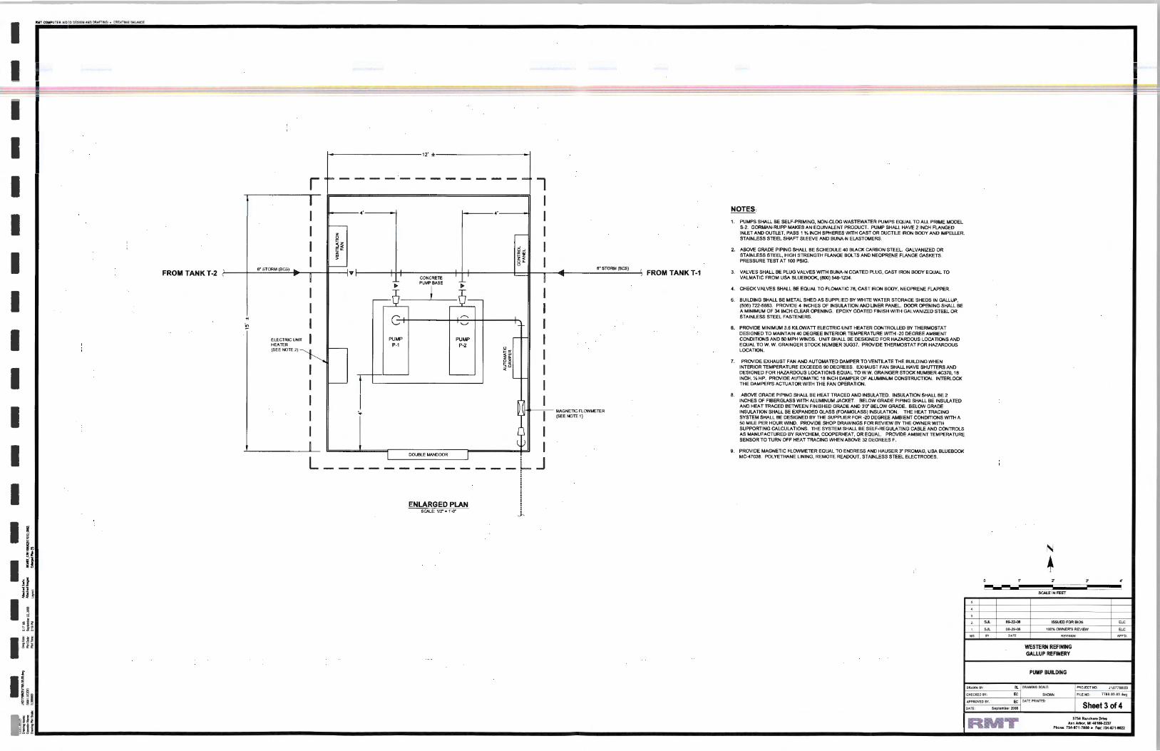
NOTES:
I ,_ PUMPS SHALL BE SELF-PRIMING, NON-CLOG WASTEWATER PUMPS EQUAL TO ALL PRIME MOOEL
I I---
I S-2. GORMAN-RUPP MAKES AN EQUIVALENT PRODUCT. PUMP SHALL HAVE 21NCH FLANGED I z ,--- INLET AND OUTLET, PASS 1 %INCH SPHERES WITH CAST OR DUCTILE IRON BODY AND IMPELLER I 0 STAINLESS STEEL SHAFT SLEEVE AND BUNA-N ELASTOMERS. I
I ~~ I ' F~ h 2. ABOVE GRADE PIPING SHALL BE SCHEDULE 40 BLACK CARBON STEEL GALVANIZED OR I
I ffi STAINLESS STEEL, HIGH STRENGTH FLANGE BOLTS AND NEOPRENE FLANGE GASKETS.
I > 0"- I PRESSURE TEST AT 100 PSIG.
- " 6' STORM (BCS) o. s• STORM (BCS)
' FROM TANK T-1 FROM TANK T-2 , ... 3. VALVES SHALL BE PLUG VALVES WITH BUNA-N COATED PLUG, CAST IRON BODY EQUAL TO
I CONCRETE ~
I VALMATIC FROM USA BLUEBOOK, (BOO) 548-1234.
~ PUMP~ BASE ~
I I I 4. CHECK VALVES SHALL BE EQUAL TO FLOMATIC 78, CAST IRON BODY, NEOPRENE FLAPPER
I - ,_ 5. BUILDING SHALL BE METAL SHED AS SUPPLIED BY WHITE WATER STORAGE SHEDS IN GALLUP,
I I (505) 722-5883. PROVIDE 4 INCHES OF INSULATION AND LINER PANEL DOOR OPENING SHALL BE A MINIMUM OF 341NCH CLEAR OPENING. EPOXY COATED FINISH WITH GALVANIZED STEEL OR
-It
I G ,.-.,. STAINLESS STEEL FASTENERS.
'!? '-' I 6. PROVIDE MINIMUM 3.6 KILOWATT ELECTRIC UNIT HEATER CONTROLLED BY THERMOSTAT
I I - I DESIGNED TO MAINTAIN 40 DEGREE INTERIOR TEMPERATURE WITH -20 DEGREE AMBIENT
ELECTRIC UNIT PUMP PUMP CONDITIONS AND 50 MPH WINDS. UNIT SHALL BE DESIGNED FOR HAZARDOUS LOCA liONS AND HEATER P-1 P-2 EQUAL TOW. W. GRAINGER STOCK NUMBER 3UG37. PROVIDE THERMOSTAT FOR HAZARDOUS (SEE NOTE 2) ~ - " I LOCATION.
~ 5 7. PROVIDE EXHAUST FAN AND AUTOMATED DAMPER TO VENTILATE THE BUILDING WHEN
I I < I INTERIOR TEMPERATURE EXCEEDS 90 DEGREES. EXHAUST FAN SHALL HAVE SHUTTERS AND
- DESIGNED FOR HAZARDOUS LOCATIONS EQUAL TO W.W. GRAINGER STOCK NUMBER 4C370, 18
I -
I INCH, Y. HP. PROVIDE AUTOMATIC 18 INCH DAMPER OF ALUMINUM CONSTRUCTION. INTERLOCK - THE DAMPER'S ACTUATOR WITH THE FAN OPERATION.
I I 8. ABOVE GRADE PIPING SHALL BE HEAT TRACED AND INSULATED. INSULATION SHALL BE 2
i INCHES OF FIBERGLASS WITH ALUMINUM JACKET. BELOW GRADE PIPING SHALL BE INSULATED
I AND HEAT TRACED BETWEEN FINISHED GRADE AND 3'0" BELOW GRADE. BELOW GRADE
I -:.. I MAGNETIC FLOWMETER INSULATION SHALL BE EXPANDED GLASS (FOAMGLASS) INSULATION. THE HEAT TRACING (SEE NOTE 1) SYSTEM SHALL BE DESIGNED BY THE SUPPLIER FOR -20 DEGREE AMBIENT CONDITIONS WITH A
50 MILE PER HOUR WIND. PROVIDE SHOP DRAWINGS FOR REVIEW BY THE OWNER WITH
I I SUPPORTING CALCULATIONS. THE SYSTEM SHALL BE SELF-REGULATING CABLE AND CONTROLS AS MANUFACTURED BY RAYCHEM, COOPERHEAT, OR EQUAL PROVIDE AMBIENT TEMPERATURE
I SENSOR TO TURN OFF HEAT TRACING WHEN ABOVE 32 DEGREES F.
I I 9. PROVIDE MAGNETIC FLOWMETER EQUAL TO ENDRESS AND HAUSER 3" PROMAG, USA BLUEBOOK I DOUBLE MANDOOR I . MC-47038. POLYETHANE LINING, REMOTE READOUT, STAINLESS STEEL ELECTROOES.
L------------- ~ J
I ! ENLARGED PLAN ~
SCALE: 112" = 1'-0'" ~
I I 1 .. N -, ~- ~ + l i: 0 ,. z ~ ..
HI !""M--- I SCALE IN FEET
I ,_
~ •-1'1 '-
tJl ,_ 5.L 09-22-08 ISSUED FOR BIOS w: ; ~ ,_ 5.L 08-29-08 100% ONNER'S REVIEW w:
!U NO. I V DATE REVISKIN APP'D. I Ell WESTERN REFINING GALLUP REFINERY
I I PUMP BUILDING
DRAWN BY: st. DRAWING SCALE: PROJECT NO: J:\077U\03
lh CHECKED BY: EC ....... Fil ENO: 7711.03.03.ciwg
APPROVED BY: EC DATE PRINTED:
Sheet 3 of4 OATE: Slpllmbtr200S
~Hi RMT 3754 R•nchl ro Drl'l• Ann Arbor, Ml 48108-2237
Phon•: 734-1171-70SO • Fu : 734-1171-8022

I RMT COt.IPUTER AIDED DESIGN AHD ORAFT1NG • CREATING BAI..AHCE
NOTES: 1. ANCHOR SOL TS SHALL BE SIZED PER PUMP SUPPlJER'S RECOMMENDATIONS.
NOTES: 1. MINIMUM 3500 PSI CONCRETE WITH AIR ENTRAINMENT
2. PROVIDE GRANULAR BACKFILL EXTENDING 3' AROUND SWIRL CONCENTRATOR 2. FLEXIBLE COUPLING, INCLUDING REDUCING COUPUNGS SHAJ...l BE
I J COMPACT TO MINIMUM 90% PROCTOR DENSITY. MAXIMUM AGGREGATE SIZE OF 1'. SINGLE-ARC. H ELASTOM. ER COUPLINGS OF BUNA-N CONSTRUCT10N.
3. SWIRL CONCENTRATION SHALL BE AQUA-SWIRL MODELAS-12. (888)-344-9044. a. MERCER RIBBON COWPAH'tf. b. RED VALVE COMPANY
4. ~~F~l:~6;.~~~~~YT~~~O~~ETERMINE PIPE CONNECTION, SIZJNG, c. USA BLUEBOOK (800-548-123()
~ -=-- - = ~ __ J" - . . . __ . _ ,. .. .....,._.._ _ _ ~- :3 PRESStiREG~~~-Ottr~-,..z.:ruL£IEB~ !5. ,.R9'wi9E Fl:Af48EI3 RIS-Ft \lt'fl'll CA!K!:T!O eevtR 'f6 SEJid:'" IE lliW4t let! l'O - - -mLES$ S !_EEL GAUG~:. WII A PVC SEAL BOOT EQU1A1L: i Q USABLDE&XJK
I I I I I I I I I I I I I I I
i d ih ~ ,;
ill ~ . • N
su xu
l COARSE AGGREGATE ) BACKFILL
PREVENT GAS EMISSIONS. STOCK NO. MC-44450 (800-548-1234)
s-
6. TIGHTEN ALL FLANGE BOLTS PER PLASTIC PIPE INSTlTUTE TECHNICAL NOTE 38.
7. CONTACT OWNER I ENGINEER IF GROUNDWATER IS PRESENT DURING EXCAVATING.
~~~~-~ I =·~ 12"MIN.[ i . ... . .. . I ~CONCRETEPAD
1· ~ I • I
NO. 6 OEF BAR 12"0.C. E.W.
I--
t--
.--- L.....-
] I SWIRL
\__ CONCENTRATOR ) (12'")
I--
I--
::J ] • J J ' ] . • 40 . • .. • ... ~ .
FLANGED CONNECTIONS OR FUSED JOINTS wtTH POLYETHYLENE COLLAR TO PROVIDE ANCHORAGE
_d POLYETHYLENE BASE FlANGED EMBEDDED IN CONCRETE
.. ~ . • • • • .. • ~~~~- BAR, 12" O.C., E.W.
ANTI-FLOTATION BASE
f'7\ \V
SWIRL CONCENTRATOR NOT TO SCALE
NOTES: 1. MINIMUM 3500 PSI CONCRETE WITH AJR ENTRAINMENT.
2. PROVIDE GRANULAR BACKFILL EXTENDING 3' AROUND SW\Rl CONCENTRATOR. COMPACT TO MINIMUM 90% PROCTOR DENSrTY. MAXIMUM AGGREGATE SlZE OF 1".
3. MANHOLE SHALL BE HOPE AS MANUFACTURED BY ISCO INDUSTRIES, (800)~276.
4 . PERFORM EXPLORATORY EXCAVATION TO DETERMINE PIPE CONNECTION, SIZJNG, AND ELEVATIONS PRIOR TO PlACING ORDER.
5. PROVIDE FLANGED RISER WITH GASKETEO COVER TO SEAL THE MANHOLE TO PREVENT GAS EMISSIONS.
6. TIGHTEN ALL FLANGE BOLTS, THEN RE-TIGHTEN 7 DAYS AFTER INITIAL INSTALLATION TO ACCOUNT FOR COlO FLOW.
NO. 6 OEF. BAR. 12" O.C., E.W. \ 2 LAYERS
t 12"
T J !
H20 CAST IRON FRAME AND COVER, GASKETEO
~\_ ~ ov ~,~ SAWCUT EXISTING PAVEMENT
l COARSE AGGREGATE ) BACKALL
60'
bb~~=
~2'
.1_ 9I 12" ... T
ETHYLENE BASE FlANGED NO. 6 DEF. BAR, 12" O.C., E.W. EMBEDDED IN CONCRETE.
2 LAYERS
I /PRESSURE GAUGE WI ¥ GAUGE GUARD
FLEXIBLE ECCENTRIC REDUCER
- --1/T GALVANIZED 1;---~~~~LL~'i.u.
STEEL PIPE
PLUG VALliE~
1-----;T
LEXIBLE ONCENTRIC EOUCER
I I [MIN&~DUY4'
17\ \V
I EMBEDMENT ANCHOR BOLTS
I T ~~~~~~~~~~ROUT
I •I" J CONCRETE PUMP BASE
.. 1 ~ ...
CENTRIFUGAL PUMP INSTALLATION NOT TO SCAlE
NOlES:
1. 3,500 PSI, AIR ENTRAINED CONCRETE.
2. ROUGHEN EXISTING CONCRETE PAD AND APPLY EPOXY BONDING COMPOUND. POUR PUMP BASE \IVHILE EPOXY IS TACKY PER SUPPLIER'S WRITIEN INSTRUCTIONS.
14' MINI LP~MP\ I ·f l . . ·. ' . ... •_j_
·t" I I : ·~· ·. > · · . . _ . .. .
NO. 6 DEFBAR 9"0.C., eN.
EXISTING CONCRETE SLAB J J J SEE NOTE2
~PROVIDE NO. 6 J.HOOKS, MIN 6 PER BASE
f7\ PUMP BASE \V NOT TO SCALE
~BUILDING WALL
0 NO. 4 DEF BAR. ~ 3500 PSI CONCRETE
12" OC EW AIR ENTRAINMENT
FINISHED GRADE \ • •
\ ----:.•..:...· ===~ b
...
4" RIGID FOAM INSULATION ALL AROUND
.. : , ... 1:
1- 1• .1
--=-,____:---'~
l GRANULAR BACKFILL COMPACTED TO 90% PROCTOR DENSITY )
PIP€~
~ v PIPE STANCHION
GALVANIZED OR STAINLESS STEEL ANCHOR BOLTS, MIN. 518• OIA, -4• EMBEDMENT
J . L FINISHED GRADE
·I r .. \ '/ /
f7\ \V
@ . .. . :.
'l~Ui ~ 1'· 6. OIA. ___j
I '"""'UC. NO. 6 OEFBAR
OUTDOOR PIPE STANCHION NOT TO SCALE
SOLID CAST IRON COVER WITH FRAME LABELED "SEWER" SIZE TO MATCH CONCRETE RING
[.. -J • .. _ •• .. • :. .. • b
0 .. .• " . .... 41 ~ .. . .. • .a. • .. .. ' .o~'
STAINLESS STEEL FASTENERS
6" GRAVEL
I FUSED 24· X 24~ X 12" TEE
~ I
~ SEWER ~ NOTE: PROVIDE 6" RISER PIPE FOR 6" FORCE MAIN
"' SEWER CLEANOUTS \V NOT TO SCALE
2. I SJL.
1. I SJL.
NO. I IIY
09-22-08 ... ,.... DATE
ISSUED FOR BIOS
100"' OWNER'S REVIEW
WESTERN REFINING GALLUP REFINERY
DETAILS
ELC
ELC
APII"D.
t
I! ~ ···-~--~ f
5
\ RMT Ann Arbor. MI 411G8-2237 ~~ ~ \.V ~•m= \.V ""'""'"·'"'"'" '~'-~ Ll __________________ ::~------------------------------------------_:~------------------------------------------------------------------.L~:;~;_----~--------~ I~Hi
12\ I DRAWNIIY: Sl 1DRAWINGSCA1.E:
CHECKED IV: EC SHOWN
PROJECT NO: J:\07718\03 POLYETHYLENE MANHOLE
\..: FIL ENO: 77811.03.M.dwg
BUILDING FOUNDATION APPROVED IIY: EC I DATE PRINTED:
DATE: September2001 Sheet4 of4 NOT TO SCALE
•=

ltl
1!111!1 ----------------------1111111
--1!111!1 -----------
ATTACHMENT D: TECHNICAL PAPER ON TANK-BASED SEPARATOR CASE STUDIES
D
Use of contents on this sheet is sub;ect to the limttations specified at the end of this document Attachment D FlysheeLdoc

,iii
-IIIII
-----IIIII
-----------------.. ---------.. -IIIII
--NATIONAL SUin 1000
1a•• L .TRt:IET. N.W.
WASHINGTON. D. C. 2003.
ENV-95-161
UPGRADING REFINERY WASTEWATER TREATMENT SYSTEMS WITH ABOVE-GROUND OUJW ATER SEPARATION TANKS:
THREE CASE HISTORIES
David R. Marrs Patrick M. Maroney Brown and Caldwell
Pleasant Hill. California
Steven L. Reynolds Chevron U.S.A Products Company
Salt Lake City, Utah
Mark J. Mielke Total Petroleum. Inc.
Alma, Michigan
Greg E. Elliot Total Petroleum, Inc . Ardmore, Oklahoma
Presented at the 1995NPRA
ENVIRONMENTAL CONFERENCE October 15-17, 1995
San Francisco, California
603

Ill
------IIIII -IIIII -IIIII -----11111!1 -IIIII -IIIII -IIIII ---------------
This paper has been reproduced for the author or authors as a courtesy by the National Petroleum Refiners Association. Publication of this paper does not signify that the contents necessarily reflect the opinions of the NPRA. its officers. directors. members, or staff. NPRA claims no copyright in this work. Requests for authorization to quote or use the contents should be addressed directly to the author(s).

ill
--.. --.. -.. ----.. --------------------111111
----
UPGRADING REFINERY WASTEWATER TREATMENT SYSTEMS WITH ABOVE-GROUND OIL/WATER SEPARATION TANKS:
THREE CASE HISTORIES
David R. Marrs Patrick M. Maroney Brown and Caldwell
Pleasant Hill, California
Steven L. Reynolds Chevron U.S.A Products Company
Salt Lake City, Utah
Mark J. Mielke Total Petroleum, Inc.
Alma, Michigan
Greg E. Elliot Total Petroleum, Inc. Ardmore, Oklahoma
Experience has shown that effective oil/water/solids separation and wasteload equalization are essential for the successful operation of refinery biological wastewater treatment systems. The performance of these upstream operations critically affects the quality of the fmal effluent from activated sludge units, especially when nitrification is a treatment objective. Upstream treatment also influences the final effluent quality that can be obtained by rotating biological contractors (RBCs) and trickling filters, both of which have short hydraulic retention times and tend to lose efficiency as free oil accumulates in the biomass.
Conventionally, wastewater treatment systems in North American refineries have included API-type gravity separators for the initial removal of free oil and solids from the influent wastewater, followed by a secondary fine oil removal step such as dissolved air flotation (DAF), induced air flotation (IAF), sand filtration, or a coalescing plate separator. Ponds were used in the past to provide surge control and perhaps some equalization upstream of the biological treatment system. However, these types of ponds have been all but eliminated in the United States as a result of regulatory changes over the last five years. Many refmeries have replaced their surge and equalization ponds with a flow-through tank of either constant or variable volume placed in line with the oil/water treatment facilities.
ENV-95-161 Page 1

Ill
""" -• -----• ----Iiiii
--------------------.. ---
Brown and Caldwell has designed numerous improvements to refmery wastewater treatment systems over the past twenty years. These projects have been driven by several factors, including improved compliance with existing NPDES permits, new and more restrictive effluent limitations, and, more recently, requirements to bring older treatment systems into compliance with various RCRA and Clean Air Act (e.g., benzene NESHAPS and Subpart QQQ) provisions. Improved oil/water/solids separation and equalization have typically been important considerations for our clients.
This paper presents design concepts and operating data for three such wastewater treatment upgrades recently completed in the United States at refmeries ranging in size from 45,000 bpd to approximately 70,000 bpd. In each case, the existing surge ponds and API separator were replaced with aboveground tanks to accomplish gravity oil/water/solids separation and wastewater equalization in a single process vessel. These tank-based separators have now been in service for over two years, demonstrating the following advantages over conventional approaches to primary wastewater treatment and equalization in refinery service:
z The objectives of surge control, influent equalization, and primary oil/water/solids separation have been achieved in a single tank. The need for a separate wastewater equalization tank has been eliminated.
z Oil/grease concentrations in tank-based separator effluents have surpassed the quality that would typically be expected from an API separator. Two of the three facilities discussed in this paper have even been able to eliminate downstream fine oil removal units (IAFs or DAFs) from their treatment systems, leading to reduced chemical and maintenance costs as well as eliminating the need to manage the emulsified oily sludges produced by flotation processes.
z The amount of operator attention required at the wastewater treatment unit has been reduced. Unlike a conventional API separator, there is no need for frequent adjustment of the oil skimmer level. Those facilities that have removed their IAFs and DAFs have also eliminated the operating nuisances associated with adjustment and maintenance of the froth skimmers.
The quality of the recovered oil has improved, reducing the processing required before this material can be recycled to the refinery.
The above-ground separation tanks are in compliance with existing RCRA and Clean Air Act regulations. Furthermore, they will be easier to upgrade than conventional below-grade gravity separators if future RCRA requirements for wastewater treatment tanks become more restrictive.
Overall, by changing the design concept for oil/water/solids separation facilities, the projects discussed in this paper have demonstrated that refinery effluent quality can be improved at lower capital and operating costs than would be expected in a conventional wastewater treatment train.
ENV-95-161 Page 2

Ill
--.. .. ----------.. -.. -----.. -.. ---.. --.. -.. ----
DEVELOPMENT OF TANK-BASED SEPARATOR CONCEPT
The development of the tank-based separator concept began in the mid 1980's when Brown and Caldwell was conducting several refinery wastewater treatment plant upgrades across the United States. At one facility in California, we replaced an in-ground stormwater surge basin with large storage tanks. The hilly terrain, local weather patterns, and regulatory requirements to contain a 25-year, 24-hour rainfall event necessitated approximately 18.5 million gallons of stormwater storage capacity. A large pumping system was also designed to send dry-weather process flows to the wastewater treatment plant and excess storm flows to the storage tanks. Retained stormwater would be sent to the API separator at a controlled rate when the storm event passed.
After the stormwater tanks were commissioned, Brown and Caldwell continued to provide consulting services to this refinery on operational and regulatory compliance issues such as benzene NESHAPS. When computing the total annual benzene content of various waste streams in 1990, we discovered that slop oil quantities from the API separator were significantly lower than historical values for this facility. Upon further review and inquiry, it was determined that the treatment plant operators were routing the entire process wastewater flow (both dry weather and wet weather) through the stormwater tanks. Free oil was separating and accumulating in the storage tanks, with the result that the downstream API separator and DAF unit were receiving much lower oil loadings .
The operation of the stormwater surge tanks at this California facility was then considered in light of other refinery wastewater treatment projects we were undertaking at the same time. Brown and Caldwell began to propose to our clients the possibility of consolidating in a single process vessel the function of primary and most probably secondary oil/water/solids separation with surge control and equalization. Total Petroleum, Inc. agreed to try this significant change to refinery wastewater treatment process design at two facilities then undergoing major upgrades. While we were confident that the tank-based separator system could produce an acceptable biotreatment feed without an IAF or DAF, space was also provided at each of these plants for a future fine oil removal system if necessary. The actual performance of these tank-based separators has been excellent, eliminating any further consideration of secondary oil removal units and persuading other refinery clients that these systems offer significant improvements over conventional wastewater treatment approaches.
Design and operational details for tank-based separators differ according to the needs and preferences of individual refineries. Nevertheless, general separator design concepts have beome established over the last several years and are illustrated in Figure 1. The separator consists of an above-ground circular steel tank equipped with a double mechanical seal floating roof, oil skimmer attached to the floating roof, and a flexible hose for draining recovered oil. A sump is provided in the tank floor for periodic sludge removal. Quiescent conditions in the tank enable free oil to separate and form a floating layer while solids settle to the bottom as sludge. The separator may be operated as either a fixed or variable volume tank, depending on whether flow equalization ahead of the biological treatment system is a process objective.
ENV-95-161 Page 3

'ltl
-.. ------------------------------------
Design considerations include the following:
Hydraulic residence time. The working volume of the tank should provide a minimum hydraulic residence time of 8-12 hours for optimum oil removal. The actual residence time in tanks designed by Brown and Caldwell has been on the order of 10-30 hours to allow for simultaneous oil/water separation and concentration equalization.
Surface overflow rate. Surface overflow rates for the tank-based separators designed by Brown and Caldwell have been in the range of 0.1-0.5 gprn!ft\ based on horizontal surface area. A design maximum overflow rate has not been established for tank-based separators of the type discussed in this paper. The overflow rates for the units i,nstalled to date are approximately an order of magnitude below comparable values for conventional API separators.
Depth of floating oil layer. The floating oil layer should be maintained well below the skimmer inlet to minimize water carryover into the recovered oil system. A minimum oil depth of two feet has been recommended on tanks designed by Brown and Caldwell.
Acid addition. Gravity separation of oil and water is optimum at slightly acidic conditions (approximately pH 6.0-6.5). Acid destabilizes oily emulsions, resulting in a more easily separable free oil. As refinery process wastewater is usually alkaline, provision should be made for sulfuric acid addition to the separator influent. It may also be necessary to add caustic to raise the separator effluent back to about pH 7 prior to biological treatment. Spent caustic may be suitable at some refineries for this neutralization step.
We generally recommend acid addition in proportion to wastewater flow rate, a strategy which requires that the akalinity of the waste stream be reasonably constant. The alternative, an on-line pH monitoring and control system, does not function well in this application because the free oil in refinery process wastewater tends to foul commercially-available pH probes.
Safety. In day to day operation, the tank-based separators raise no safety concerns which are unusual in a refinery environment. Nevertheless, wastewater treatment plant operators must be aware of the potential for accumulation of explosive vapors under the floating roof covers and plan oil skimming and maintenance activities accordingly.
These types of oil/water separation tanks must comply with the design requirements of the New Source Performance Standards (NSPS) for refinery wastewater treatment systems promulgated at 40 CFR 60.690-699. In locations subject to extreme cold weather, fixed external roofs are recommended with an internal floating roof (as shown in Figure 1). Manways must be provided in the fixed and
ENV-95-161 Page 4
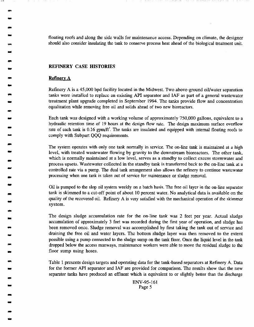
Ill
lll'!llli
----------.. ---------.. ----------------
floating roofs and along the side walls for maintenance access. Depending on climate, the designer should also consider insulating the tank to conserve process heat ahead of the biological treatment unit.
REFINERY CASE HISTORIES
Refinery A
Refinery A is a 45,000 bpd facility located in the Midwest. Two above-ground oil/water separation tanks were installed to replace an existing API separator and IAF as part of a general wastewater treatment plant upgrade completed in September 1994. The tanks provide flow and concentration equalization while removing free oil and solids ahead of two new bioreactors.
Each tank was designed with a working volume of approximately 750,000 gallons, equivalent to a hydraulic retention time of 19 hours at the design flow rate. The design maximum surface overflow rate of each tank is 0.16 gpm/f( The tanks are insulated and equipped with internal floating roofs to comply with Subpart QQQ requirements.
The system operates with only one tank normally in service. The on-line tank is maintained at a high level, with treated wastewater flowing by gravity to the downstream bioreactors. The other tank, which is normally maintained at a low level, serves as a standby to collect excess stormwater and process upsets. Wastewater collected in the standby tank is transferred back to the on-line tank at a controlled rate via a pump. The dual tank arrangement also allows the refinery to continue wastewater processing when one tank is taken out of service for maintenance or sludge removal.
Oil is pumped to the slop oil system weekly on a batch basis. The free oil layer in the on-line separator tank is skimmed to a cut-off point of about 10 percent water. No analytical data is available on the quality of the recovered oil. Refinery A is very satisfied with the mechanical operation of the skimmer system.
The design sludge accumulation rate for the on-line tank was 2 feet per year. Actual sludge accumulation of approximately 3 feet was recorded during the ftrst year of operation, and sludge has been removed once. Sludge removal was accomplished by first taking the tank out of service and draining the free oil and water layers. The bottom sludge layer was then removed to the extent possible using a pump connected to the sludge sump on the tank floor. Once the liquid level in the tank dropped below the access manways, maintenance workers were able to move the residual sludge to the floor sump using hoses.
Table 1 presents design targets and operating data for the tank-based separators at Refinery A. Data for the former API separator and IAF are provided for comparison. The results show that the new separator tanks have produced an effluent which is equivalent to or slightly better than the discharge
ENV-95-161 Page 5

Ill .. ---------------------------.. -----.. ---
from the former treatment units. Concentrations of oil/grease and total suspended solids (TSS) are acceptable for the downstream bioreactors, which consist of two parallel aeration tanks operated without biosolids recycle. In addition, removal of the IAF unit from the wastewater treatment train has eliminated management of IAF float as an operating concern.
As originally designed and operated, the wastewater treatment upgrade at Refinery A included sulfuric acid addition to the separator tank influent. Acid was added proportionally to the wastewater flow rate to achieve approximately pH 6 in the on-line tank. Spent caustic was used to neutralize the separator tank effluent prior to the bioreactors. Acid addition was discontinued after about four months because of odor problems at the bioreactor tanks. The odors were traced to the spent caustic in the wastewater. There has been no noticeable deterioration of separator tank effluent quality since acid addition ceased. Nevertheless, Refinery A plans to resume adding sulfuric acid to the separator tank influent once in-plant process modifications are completed to reduce sulfide and mercaptan levels in the spent caustic stream fed to the bioreactors.
Refinery B
Refinery B has a rated crude capacity of 45,000 bpd and is located in the West. Two above-ground oil/water separation tanks have been in service since March 1993 to treat process wastewater upstream of an existing IAF unit. RBCs provide biological treatment downstream of the IAF. The tanks were initially installed as part of a project to bring the refinery into compliance with NSPS and benzene NESHAPS requirements and have since replaced the existing API separator.
The separator tanks at Refinery B each have a working capacity of approximately 1.05 million gallons. The system is designed to operate with one tank in service and one on standby to manage excess flow and process upsets. The on-line tank provides a hydraulic retention time of 11.5 hours at the design flow rate of 1,500 gpm. The design surface overflow rate is 0.38 gpm/feat the design maximum flow. Actual wastewater flow rates have averaged about half the design flow.
The tanks are equipped with external floating roofs, with the oil skimmers attached to the roofs. Roof seals have not been replaced since start-up. Side-mounted mixers have been provided near the bottom of the tanks. The tanks are not insulated, and there is no capability to add sulfuric acid to the influent wastewater, which is typically in the range of pH 7.5-8.0. On the basis of operating experience, Refinery B has determined that addition of a chemical demulsifier to the separator influent significantly improves oil/grease removal.
For the February-September 1995 operating period, the average effluent oil/grease concentration for the on-line separator tank was 79 mg/L; the median oil/grease concentration was 50 mg/L. The average flow was 793 gpm.
ENV-95-161 Page 6

Iii
------111!111 ---------... -... -------------------
Recovered oil is removed from the on-line separator tank weekly. Refmery B operates the oil skimmer to maintain a minimum free oil thickness of three feet in the tank. No BS&W measurements are available for the recovered oil. However, refinery staff report that oil collected from the separator tanks contains much less water than recovered oil from the former API separator. As a result, operating problems in the slop oil system have decreased since start-up of the separator tanks.
Liquid sludge accumulation in the on-line tank is estimated at 8 feet per year. Refmery B reports no unusual problems in removing bottom sludge, which separates as a pumpable liquid with high water content. Sludge removal has been accomplished by taking the on-line tank out of service, draining the free oil and free water layers, suspending the sludge layer with the mechanical mixer, and pumping the sludge from the tank through a floor drain. The only sludge removal event completed to date at Refmery B took one separator tank out of wastewater service for approximately 6 weeks.
Refinery C
Refinery C is a 68,000 bpd facility located in the Southwest. Two above-ground oil/water separation tanks were installed to replace and existing API separator and IAF during a wastewater treatment plant upgrade completed in August 1994. The tanks remove free oil and solids while equalizing process wastewater ahead of two new bioreactors operated without biosolids recycle. Stormwater and process wastewater are segregated at this refmery .
The separator tanks at Refinery C are each designed with a maximum working capacity of 720,000 gallons. Both tanks are on-line and operated in parallel, an arrangement which is possible because the separators do not have to accommodate stormwater surges. The hydraulic retention time for both tanks at the design flow rate is 29 hours. The design maximum surface overflow rate is 0.13 gpm/fe. Average process wastewater flow rates are slightly less than half the design maximum.
The tanks are equipped with external floating roofs, with oil skimmers attached to the roofs. Oil is drained by gravity on a daily basis to the recovered oil system. The quality of the recovered oil is very good, typically less than 0.1% BS&W. Since the separator tanks have come on line, Refinery B has been able to return this recovered oil directly to the crude unit, bypassing slop oil treatment. According to plant staff, this was not possible with the recovered oil skimmings from the former API separator.
For the period August 1994-August 1995, the average effluent oil/grease concentration for the separator tanks at Refinery C was 42 mg/L. The average flow rate was 358 gpm.
Refinery C continuously injects spent sulfuric acid from boiler feedwater treatment into the separator tank influent. Caustic is also added as necessary to maintain the separators within the operating target of pH 6.5-7.5. Additional caustic is added to the separator tank effluent as needed to adjust process wastewater pH prior to the bioreactors.
ENV-95-161 Page 7

Ill
"""' -"""' -----------------------------------
Sludge accumulation in each tank is estimated at about 5 feet per year. To date, sludge has not been removed from either tank Based on sampling and visual observations, the bottom sludge appears to bean easily pumpable liquid. Initial plans at Refinery C call for the separator tanks to remain on line during the first sludge removal event, which is scheduled for 1996.
SUMMARY AND CONCLUSIONS
Design and operating data for the three case histories presented in this paper are summarized in Table 2. These results, along with the supporting information discussed above, clearly show that aboveground oil/water separation tanks are a viable and proven alternative to conventional API separators for refinery wastewater service. By achieving the objectives of surge control, influent equalization, and oil/water/solids separation in a single process vessel, this design concept offers refiners the opportunity to meet their wastewater treatment objectives at lower capital and operating cost than would be expected from conventional process designs.
ENV-95-161 Page 8

i ~ I
11!111
-----11!111
-------------------------------
Table 1.
Performance of Oil/Water Separation FadHties at Refinery A
Former Treatment System• API Separator IAF
New Separator Tanks Design Actualb
• January 1991 -March 1992 b September 1994- August 1995
521 421
645 420
Table2.
300 80
45 70
350 110
96 83
Summary of Design Criteria and Performance Data for Above-Ground Oil/Water Separation Tanks
A
B
c b
• Calculated with one tank on line at design flow rate b Calculated with two tanks on line at design flow rate c Median value
ENV-95-161 Page 9
70
42

I I I I I I I I I I I I I I I I I I I I I I I I I I I I I I I I I I t I I I
Sulfuric Acid
Process Wastewater
Flgure1 Tank-Based Oil/Water Separator
ENV-95-161
Internal Floating Roof
--Oil Layer
011 Skimmer
Separator Effluent
R~> 011
8122-01

Iii
-----------.. --------------------------
ATTACHMENT E: MEMBRANE BIOREACTOR PILOT STUDY
E
Use of contents on this sheet is subject to the limitations specified at the end of this document Attachment E Flysheet.doc

Iii
!!!Jill --.. -.. -.. ---.. ---------.. ----------------
Membrane Bioreactor Study May - August 2008
Prepared by
Gaurav Rajen, Environmental Engineer
Reviewed by
Ed Riege, Environmental Manager

lil
-----------------------------------.. --
1.0 Introduction This report describes the findings of a wastewater treatability study conducted at the Gallup Refinery of Western Refining using a small-scale membrane bioreactor (MBR) system leased from GE Water and Process Technologies. 1
Figure 1 presents a schematic of the system, and Figures 2 and 3 present photographs of some key components.
Permeate
Aerobic Tank Anaerobic Tank
0
~~ Feed
Air Stirrer
Membranes
Recycle of Activated Sludge
Figure 1: Schematic of Small-scale Membrane Bioreactor System

Figure 2: Photograph of the Anaerobic Tank
Figure 3: Photograph of the Aerobic Tank with Submerged Membrane Filters (lower left of picture)

2.0 Operational Procedures Wastewater from the refinery was collected from the existing aeration lagoon system at the influent pipes. This wastewater was a mixture of the industrial wastewater generated within the refinery, as well as sanitary effluent received from the Pilot Travel Center. Periodic samples of this feed were taken. The feed was collected in three large tanks, and measured amounts of phosphates and other balancing chemicals were added. This feed was then pumped into an anaerobic tank in which it was continually stirred. From the anaerobic tank, the wastewater entered an aerobic tank which had a continuous supply of air pumped into it. We also twice added approximately 5 gallons of sludge from the City of Gallup's wastewater treatment plant to this tank. The wastewater then was filtered through a set of membrane filters that were hanging in the aerobic tank, and permeate was collected for further testing. These membranes had the capability to send a backpulse of air that kept them free of clogging.
3.0 Data and Measurements Various operational parameters were measured during the study. Among these were pressures and flow rates before and after the back-pulse, pH and temperatures in the various tanks, Dissolved Oxygen levels in the anaerobic and aerobic tanks, and the Dissolved Oxygen Uptake Rate in the aerobic tank. Table I presents the maximum and minimum values for some of these parameters.
Feed and permeate samples were collected and sent to an environmental laboratory for testing, and at various times aerobic tank liquids were also sampled. Table 2 presents some of these analytical data. All of the analytical data collected will be included in our 2008 Annual Groundwater Report which has a section on all water quality monitoring activities conducted at the Gallup Refinery of Western Refining.
Table 1: Representative Set of Operational and Other Parameters Measured During the Study
Feed Permeate Dissolved Dissolved Dissolved Temperature pH pH Oxygen Oxygen Oxygen Anaerobic
Uptake Anaerobic Aerobic tank Rate Tank tank (mg/L.hour) (mg/L) (mg/L) COC)
Maximum 8.52 8.55 69 10.6 12.63 29.8 Minimum 5.73 6.5 30 0.19 0.76 5

Table 2: Representative Set of Sampling Data (all units in mg/L unless noted otherwise)
Type of Oil Total Ammonia Total Turbidity Chemical Biochemical sample and Phenolics Dissolved (NTU) Oxygen Oxygen
Grease Solids Demand Demand Feed 690 17000 600 3200 2300 3440 1288 Permeate 1.2 290 480 3800 Non- 1720 765
detect
Oil and Grease and Phenolics were dramatically reduced as is clear in Table 2. However, Ammonia levels did not drop considerably. Figure 4 depicts a graph comparing Ammonia levels in the Feed and the Permeate. Figure 5 depicts reductions in Chemical Oxygen Demand; and Figure 6 depicts reductions in Biochemical Oxygen Demand. These measures of water quality were markedly improved.
Ammonia Removal
700
600
• ~ . 500
~
::J 400 ill .5. z £ 300 z
• •• : .,. • •
200
100
0
Date
1--Feed Ammonia -+- Permeate Ammonia I
Figure 4: Graph of Ammonia Levels in the Feed and Permeate

::::r 'ill .5. c c 0
Western Refinery - COD Removal
5000
4500 • 4000
3500 • 3000
2500
2000
~ 1500
1000
• -500 •• • • • 0 +---~--~--~--~--~--~·-·~-~--~--~--~--~--~--~--~--~--~--~~ #' # ... ~~ #' _ .......
" q{ ¥ .0: fl'" Date
1--.-Feed ---Permeate I
Figure 5: Graph of Chemical Oxygen Demand Levels in the Feed and Permeate
Western Refinery - BOD Removal
1800
• 1600
1400
• 1200
::::r 1000 'ill
.5. • c 0 800 • ID
600
400
200 • • 0 • •• • • ~ ..... "
~~ ~~ . ,)~ ~-)~ .,)~ ~~ ~~ ~~ ~~ ~ ~ ~ ~ ~ ~ / ? ~ Date
1---- Feed ...... Permeate I
Figure 6: Graph of Biochemical Oxygen Demand Levels in the Feed and Permeate

4.0 Conclusions
The results of the MBR study did not favor proceeding forward with a larger scale system. What became readily apparent through the course of the study was that the refmery wastewater would need to undergo second-stage oil-water separation for the bioreactor to be effective. Currently the refinery wastewater only undergoes primary gravity-based oil-water separation in an API Separator.
There was a fear of the membrane filtration system being clogged by the oil in the refinery wastewater. This fear was expressed by GE representatives when we suggested spiking the feed with oil. We also had at various times the bacteria in the anaerobic and aerobic tanks suffer a loss of productivity - this was from a die-off caused by system malfunctions, such as clogged switches, failed pumps, ruptured tubing, all of which could be traced to the levels of oil and grease and other solids in the wastewater that the MBR system was not optimized to treat. .
We realized that the MBR system would probably be most effective in a non-refinery setting. To make it effective for our applications, we would need more oil-water separation, better screening and pre-filtration to protect the membranes.
We also found from a survey of the refining industry that MBRs are not in use at refineries to treat wastewater, but are in some use at refineries for treating process water. A recent survey of new technologies for refinery wastewater by a Task Force made up of Purdue University' s Calumet Water Institute and Argonne National Laboratoif reached these conclusions regarding MBRs in a refinery setting -
"The effectiveness, small footprint, and high effluent quality ofMBR technologies are counterbalanced by higher costs, higher energy use, waste generation, and still unresolved fouling issues that may provide inconsistent performance and reliability. Although their use in treating refmery wastewater is currently limited, significant interest in MBR technologies is growing in the refinery sector because they promise to achieve advanced effluent quality for ammonia, TSS, and many other effluent parameters. This interest reflects the significant growth and increasing efficiency of MBRs worldwide. More testing of these technologies will be needed to understand and optimize their performance under specific loading rates, their energy lifecycle inputs, their overall costeffectiveness in real application scenarios, and the generation of secondary waste. Just as importantly, more testing will be needed to understand their ability to provide integrated treatment by removing other refinery pollutants and heavy metals at the required levels."
1 http://www.gewater.com/index.jsp 2
http://www.calumet.purdue.edu/pwi/emergtech!Phase%201%20Final%20Report 10202008.pdf

ATTACHMENT F: AGGRESSIVE BIOLOGICAL TREATMENT CALCULATIONS
~ R :· \\ \ , '• r. I \ I f) ·~ ~ I I
F
Use of contents on this sheet is subject to the limitations specified at the end of this document. Attachment F Flysheet.doc

BROWN AND
CALDWELL
Residence Time for Bioreactors
Tank Dimensions
Number, n
Diameter, d
Liquid Height, h1iq
Surface Area, sa
n := 2
d := 75 ·ft
hliq := 21 ·ft
2 sa= 4418ft
Liquid Volume per tank, voltank vol1iq.tank := sa · hliq
Total Liquid Volume, vol
Flow Conditions
Average Flow, Total, qavg
Peak Flow, Total, qpeak
Average Flow, per tank, qavg.tank
Peak Flow, per tank, qpeak.tank
Client: Western Refining Client Number: 135741 Task Number: 021.300
volliq .tank = 694006 gal
volliq := volliq.tank. n
vol1iq = 1388013gal
qavg := 413 ·gpm
qpeak := 644 ·gpm
qavg qavg.tank := -
n
qavg.tank = 206.5gpm
qpeak qpeak.tank := -
n
qpeak.tank = 322 gpm
Date Started: 02/18/09 Last Modified: 02/23/09 Calc. By: JA Checked: KV
Residence Times for Bioreactors
Residence Time.xmcd
Page: 1 of 2

BROWN AND
CALDWELL
Residence Time
volliq .tank Hydraulic Residence Time, Average Flow, tr.avg tr.avg :=
qavg.tank
Hydraulic Residence Time, Peak Flow, tr.peak
tr.avg = 2.3 day
volliq.tank tr.peak := _ __;__
qpeak.tank
tr.peak = 1.5 day
Residence Times for Bioreactors
At average and peak flow conditions the residence time in the Bioreactors meets the aggressive biological treatment requirement of <5 days.
Client: Western Refining Client Number: 1357 41 Task Number: 021 .300
Date Started: 02/18/09 Last Modified: 02/23/09 Calc. By: JA Checked: KV
Residence Time.xmcd
Page: 2 of 2

BROWN AND
CALDWELL
Aeration Power Level of Bioreactors
Aeration Power Level of Bioreactors
A blower manufacturer;s selection curve (attached) shows 106 bhp required when the airflow is 1350 scfm, design airflow of blower is 1300 scfm per tank. Therefore the actual operating power per tank will be:
Number of tanks, n
Diameter, d
Surface Area, sa
Liquid Depth, hliq
Liquid Volume, vol1iq
Power Level per tank, P 1
Poperating := [1300· ft~ )' ·[ 106 . bhp ) mm 1350 ft3
min )
P operating = 102.1 bhp
n := 2
d := 75-ft
2 sa= 4418ft
hliq := 21ft
volliq := sa· h1iq
vol1iq = 694006 gal
Poperating Pt := __ _;;..
vol1iq
bhp P1 = 147--
6 10 gal
The aeration power level of 147 hp per million gallons meets the aggressive biological treatment requirement of greater than 6 hp per million gallons.
Client: Western Refining Client Number: 1357 41 Task Number: 021.300
Date Started: 02/18/09 Last Modified: 02/23/09 Calc. By: JA Checked: KV
Powerlevel.xmcd
Page: 1 of 1

It~~~~ "IOMEGA/OMEGA PLUS ROTARY BLOWERS f);g; iiti: -PACKAGE RECOMMENDATIONS -
Project: Gallup Bioreactor
INPUT DATA:
Operating mode: Gauge pressure
Kind of package: Standard Package
Distributor : BC
Flow medium : dry air
Specific heat constant 1e :
02/15/09
PAGE 1
1.40
Inlet temperature : 95
Inlet pressure : 11.3 psi
Specific weight at standard conditions :
Pressure difference :
0.077 lb/ fP
10.2 psig
Discharge pressure : 21.5 psi
ATTENTION:Is the place of installation above of 3300 ft. Please ensure that the motor is sufficiently cooled!
Technical data: NOTE: ACCESSORIES SHOWN ARE INTENDED FOR AIR USE ONLY.
Package: FB 790P Motor power: 125.0 hp Operating voltage: 460V/ 60Hz
Accessories: yes Relief valve: 2x 2 1/2" D Unloaded start up valve: 60/S D Check plate: 1 0" D Temperature gauge: D Temperature gauge with switch point: D Pressure gauge: D
Performance data: max. load
Blower speed: 2600
Connection DN: 1 0" % of maximum speed: 76
no yes D D D
Maintenance indicator mounted in s. enclosure: D Inlet silencer-suction out of room:
Inlet silencer-suction out of pipe:
D Sound enclosure-suction out of room: D Sound enclosure-suction out of pipe: D Spool piece for relief valve:
Spool piece for RV and unloaded start up valve:
design point
D D D D D D
Pressure difference LiP: 12.0 psig 10.2 psig
Inlet flow Q1: 1829 icfm
Q1 Standard*: Standard conditions 14.7 psia, 68°F and 36% RH
Discharge temp.*: Motor shaft power with belt losses + dirty filter* : 132.9 hp
Blower shaft power*:
1857 icfm
1350 scfm
114.9 hp
106.0 bhp
rpm
no D D D D D D D
Sound pressure level** : without 96 dB(A) with enclosure 78 dB(A)
* Performance data to DIN ISO 1217, part 1, annex C The pressure difference at max. load corresponds to relief valve setting I
** Measured to PN 8 NTC 2.3, 1 meter distance, free field measurement with sound isolated pipework.
Minimum input power required includes additional dirty filter losses of approx. 40 mbar.
Motor shaft power includes belt losses! Attention OMEGA 23, 43 and 63 model blowers can be run over 12 psig, but requires factory APPROVAL, a limited warranty may apply.
V 7.0 AD VERSION 03/20/02