Embed Size (px)
Citation preview
www.versa-valves.com
®
ISO 9001
CERTIFIED
BULLETIN PCg-2001
SOLENOID VALVES FOR THE PROCESS CONTROL INDUSTRY
AIR VALVES FOR INDUSTRY SINCE 1949
Versa Products Company, Inc., 22 Spring Valley Road, Paramus, New Jersey, USA 07652 • TEL:201/843-2400 FAX: 201/843-2931e-mail: [email protected]
Versa BV., Halstraat 3, 7321 AG Apeldoorn, The Netherlands • TEL:+31-55-3681900 FAX: +31-55-3681909e-mail: [email protected]
pneu
air
e
3
®
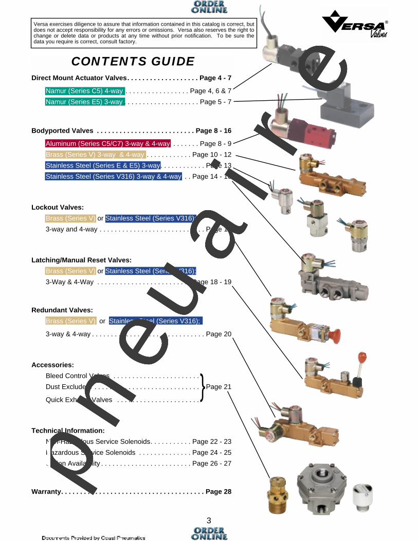
CONTENTS GUIDE
Versa exercises diligence to assure that information contained in this catalog is correct, butdoes not accept responsibility for any errors or omissions. Versa also reserves the right tochange or delete data or products at any time without prior notification. To be sure thedata you require is correct, consult factory.
Direct Mount Actuator Valves. . . . . . . . . . . . . . . . . . . Page 4 - 7
Namur (Series C5) 4-way . . . . . . . . . . . . . . . . . Page 4, 6 & 7
Namur (Series E5) 3-way . . . . . . . . . . . . . . . . . . . . Page 5 - 7
Bodyported Valves . . . . . . . . . . . . . . . . . . . . . . . . . . Page 8 - 16
Aluminum (Series C5/C7) 3-way & 4-way . . . . . . . Page 8 - 9
Brass (Series V) 3-way & 4-way . . . . . . . . . . . . Page 10 - 12
Stainless Steel (Series E & E5) 3-way. . . . . . . . . . . . Page 13
Stainless Steel (Series V316) 3-way & 4-way . . Page 14 - 16
Lockout Valves:
Brass (Series V) or Stainless Steel (Series V316);
3-way and 4-way . . . . . . . . . . . . . . . . . . . . . . . . . . . . Page 17
Latching/Manual Reset Valves:
Brass (Series V) or Stainless Steel (Series V316);
3-Way & 4-Way . . . . . . . . . . . . . . . . . . . . . . . . . Page 18 - 19
Redundant Valves:
Brass (Series V) or Stainless Steel (Series V316);
3-way & 4-way . . . . . . . . . . . . . . . . . . . . . . . . . . . . . . Page 20
Accessories:
Bleed Control Valves . . . . . . . . . . . . . . . . . . . . . . .
Dust Excluders . . . . . . . . . . . . . . . . . . . . . . . . . . . . . Page 21
Quick Exhaust Valves . . . . . . . . . . . . . . . . . . . . . .
Technical Information:
Non-Hazardous Service Solenoids. . . . . . . . . . . Page 22 - 23
Hazardous Service Solenoids . . . . . . . . . . . . . . Page 24 - 25
Option Availability . . . . . . . . . . . . . . . . . . . . . . . . Page 26 - 27
Warranty. . . . . . . . . . . . . . . . . . . . . . . . . . . . . . . . . . . . . . Page 28
}
pneu
air
e

4
General DescriptionThe Versa C5 NAMUR mount control valveis a high flow, 5-port, solenoid/pilot valve. It isdesigned to mount directly to any NAMURactuator, thus reducing actuator response timeand cost of tubing, fittings, brackets, andlabor. Many adaptor kits are available fornon-NAMUR actuators. Consult factory for kitavailability.The 5-port design allows the C5 NAMUR to beordered as either 4-way (for double acting actuators) or3-way (for spring return or fail-safe actuators). The function ofthis valve is field convertible utilizing no special tools, gaskets,or sealants. Relocation of a port plug converts a 3-way to a 4-way, or a 4-way to a 3-way. When the 4-way valve is convertedto 3-way function, the unused exhaust port becomes an actua-tor vent into which a filter/muffler can be installed to preventcontaminents from entering either the valve or the actuator.Single solenoid models (for 2-position control), or double sole-noid models (for 2 or 3-position control) are available. Actuatorpositioning is possible with the use of 3-position valves since allVersa C5 NAMUR valves are leakfree/bubbletight. A completeselection of electrical connections, area classifications, and
power requirements makes the most exacting and demandingspecifications or applications easy to satisfy. Manual overrides(guarded-push to operate) are standard on all C5 NAMURvalves. Consult factory for other manual overides available asan option.
MaterialsValve body and plunger: anodized aluminum (for stainless
steel direct mount valve, consult factory)Actuating Caps: solenoid—anodized aluminum
spring cap—synthetic resinValve seals: plunger and body— FKM (fluorocarbon)
pilot piston— NBR (nitrile)valve/actuator mounting O rings— NBR (nitrile)
Pilot Piston: synthetic resinScrews: stainless steel (except valve to actuator = carbon steel)Port plug: brassSolenoid parts: sleeve, plunger & spring— 304 & 430F
stainless steel coils—epoxy encapsulated with 3 spadeterminals (std) or 2 or 3 wire lead (opt)
coil cover— (when applicable) option:–C50 = carbon steel, painted;—LB—XN, —LB—XX,—PC,—PC—XN,—PC—XX, —XN,—XX= carbon steel,
zinc chromate plated
Basic Valve Number*
CXX-3234-NB1 -†- (coil code)CXX-3294-NB1 -†- (coil code)
CXX-4234-NB1-†- (coil code)CXX-4294-NB1 -†- (coil code)
3-way**
3/2 & 3/3
4-way
5/2 & 5/3
FUNCTION**
1/4 NPTG1/4
1/4 NPTG1/4
PORT SIZE
.75 (11)
.75 (11)
.75 (11)
.75 (11)
Cv (Kv)
CGS-3232-NB1 -†- (coil code)CGS-3292-NB1 -†- (coil code)
CGS-4232-NB1 -†- (coil code)CGS-4292-NB1 -†- (coil code)
SINGLE SOLENOID/SPRING RETURN, 2 POSITION
CGG-3232-NB1 -†- (coil code)CGG-3292-NB1 -†- (coil code)
CGG-4232-NB1 -†- (coil code)CGG-4292-NB1 -†- (coil code)
DOUBLE SOLENOID/DETENT, 2 POSITION
CXX-3233-NB1 -†- (coil code)CXX-3293-NB1 -†- (coil code)
CXX-4233-NB1 -†- (coil code)CXX-4293-NB1 -†- (coil code)
DOUBLE SOLENOID/SPRING CENTERED, 3 POSITIONBlocked Center Exhaust Ports Open
DIRECT MOUNT ACTUATOR VALVESSERIES C5 NAMUR
3-Way/4 Way Field Convertible Solenoid Valves
Porting SizeInlet and exhaust — 1/4 NPT or G1/4Cylinder ports — O ring seal per NAMUR standard (For
non-NAMUR actuators, consult factory)
Installation, Filtration and LubricationValves have no limitations on mounting orientation. 40 to 50 micron filtration and general purpose lubricating oil ISO,ASTM viscosity grade 32 recommended.Ambient temperature range 5°F (15°C) to 125°F (50°C).
Flow RatesCv = 0.75 (Kv = 11) average for all ports (48 SCFM at 100 psi;82 Nm3/h at 7 bar).For actuator speed rates see page 6.
Options SuffixManual Override: none Standard on basic valves,
guarded-push to operate.All other options see page 6.
Operating Pressures and Weights
* All valves include O ring interface seals and #10-24 mounting screws.For #10-32 screws change NB1 to NB2. For M5 screws change NB1 to NB3.
** 3-way is the same valve as 4-way, but is provided with a relocated cylinder port plug. See note on page 7
C5 NAMUR ValveProduct Number Selector
†† Pressure ranges may changebased on solenoid option. See page 6.
MPa = bar10
For higher pressure applications, consult factory.
Valve TypeApproximate WeightsOperating
Pressure Range††
Pneumatic
Double Solenoid/spring centered(3-position)
Double Solenoid/detented(2-position)
Single Solenoid/spring return(2-position)
15-115 psi(1-8 bar)
10-115 psi(0.7-8 bar)
15-115 psi(1-8 bar)
1.2 lbs.(545 g)
1.2 lbs.(545 g)
0.8 lbs.(363 g)
OrdinaryService
HazardousService1.1 lbs.(500 g)
1.8 lbs.(816 g)
1.8 lbs.(816 g)
For coil code see page 6.†Add suffix option here, if required.
ALUMINUM CONSTRUCTION
pneu
air
e
5
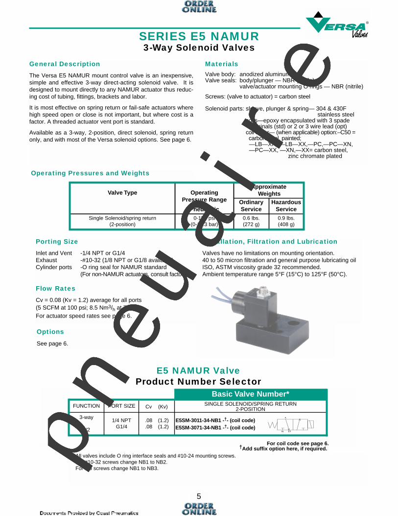
SERIES E5 NAMUR3-Way Solenoid Valves
General Description
The Versa E5 NAMUR mount control valve is an inexpensive,simple and effective 3-way direct-acting solenoid valve. It isdesigned to mount directly to any NAMUR actuator thus reduc-ing cost of tubing, fittings, brackets and labor.
It is most effective on spring return or fail-safe actuators wherehigh speed open or close is not important, but where cost is afactor. A threaded actuator vent port is standard.
Available as a 3-way, 2-position, direct solenoid, spring returnonly, and with most of the Versa solenoid options. See page 6.
MaterialsValve body: anodized aluminumValve seals: body/plunger — NBR (nitrile)
valve/actuator mounting O rings — NBR (nitrile)
Screws: (valve to actuator) = carbon steel
Solenoid parts: sleeve, plunger & spring— 304 & 430Fstainless steel
coils—epoxy encapsulated with 3 spadeterminals (std) or 2 or 3 wire lead (opt)
coil cover— (when applicable) option:–C50 = carbon steel, painted;—LB—XN, —LB—XX,—PC,—PC—XN,—PC—XX, —XN,—XX= carbon steel,
zinc chromate plated
Operating Pressures and Weights
Porting Size
Inlet and Vent -1/4 NPT or G1/4Exhaust -#10-32 (1/8 NPT or G1/8 available)Cylinder ports -O ring seal for NAMUR standard
(For non-NAMUR actuators, consult factory)
Flow Rates
Cv = 0.08 (Kv = 1.2) average for all ports (5 SCFM at 100 psi; 8.5 Nm3/h at 7 bar).For actuator speed rates see page 6.
Installation, Filtration and Lubrication
Valves have no limitations on mounting orientation. 40 to 50 micron filtration and general purpose lubricating oilISO, ASTM viscosity grade 32 recommended.Ambient temperature range 5°F (15°C) to 125°F (50°C).
Valve Type OperatingPressure Range
Pneumatic
ApproximateWeights
Single Solenoid/spring return(2-position)
0-150 psi(0-10.3 bar)
0.6 lbs.(272 g)
OrdinaryService
0.9 lbs.(408 g)
HazardousService
Basic Valve Number*FUNCTION PORT SIZE Cv (Kv) SINGLE SOLENOID/SPRING RETURN
2-POSITION
1/4 NPTG1/4
.08 (1.2)
.08 (1.2)E5SM-3011-34-NB1 -†- (coil code)E5SM-3071-34-NB1 -†- (coil code)
3-way
3/2
A
IN EX
E5 NAMUR ValveProduct Number Selector
* All valves include O ring interface seals and #10-24 mounting screws.For #10-32 screws change NB1 to NB2.For M5 screws change NB1 to NB3.
For coil code see page 6.†Add suffix option here, if required.
Options
See page 6.
pneu
air
e
6
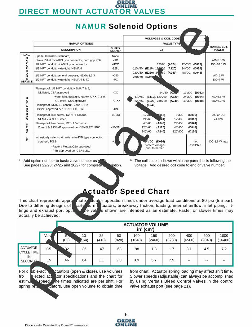
DIRECT MOUNT ACTUATOR VALVES
NAMUR Solenoid Options
* Add option number to basic valve number as suffix.See pages 22/23, 24/25 and 26/27 for complete description.
** The coil code is shown within the parenthesis following the voltage. Add desired coil code to end of valve number.
This chart represents approximate actuator operation times under average load conditions at 80 psi (5.5 bar).Due to differing designs of quarter-turn actuators, breakaway friction, loading, internal airflow, inlet piping, fit-tings and exhaust port options, the values shown are intended as an estimate. Faster or slower times mayactually be achieved.
Actuator Speed Chart
ValveType
ACTUATORCYCLE TIME
INSECONDS
C5
1000(16400)
600(9840)
400(6560)
200(3280)
150(2460)
100(1640)
50(820)
25(410)
10(164)
5(82)
E5
7.24.53.11.71.3.98.63.47.36.32
------7.55.73.92.01.1.64.46
ACTUATOR VOLUMEin3 (cm3)
For double-acting actuators (open & close), use volumesfrom selected actuator specifications and the chart forestimated speed. The times indicated are per shift. Forspring return actuators, use open volume to obtain time
from chart. Actuator spring loading may affect shift time.Slower speeds (adjustable) can always be accomplishedby using Versa’s Bleed Control Valves in the controlvalve exhaust port (see page 21).
NON-HAZARDOUS
SERVICE
NAMUR OPTIONS VALVE TYPE
SUFFIX NOMINAL COILDESCRIPTION DETAIL* C5 E5 POWER
Spade Terminals (standard) None
Strain Relief mini-DIN type connector, cord grip PG9 -HC AC=8.5 W
1/2 NPT conduit mini-DIN type connector -HCC 24V60 (A024) 12VDC (D012) DC=10.5 W
1/2 NPT conduit, watertight, NEMA 4 -228L 110V50 (E110) 120V60 (A120) 24VDC (D024)
1/2 NPT conduit, general purpose, NEMA 1,2,3 -C50220V50 (E220) 240V60 (A240) 48VDC (D048)
AC=6 W
1/2 NPT conduit, watertight, NEMA 4 & 4X -PC240V50 (E240)
DC=7 W
Flameproof, 1/2 NPT conduit, NEMA 7 & 9,
UL listed, CSA approved -XX
-watertight, dusttight, NEMA 4, 4X, 7 & 9,24V60 (A024) 12VDC (D012)
AC=5.6 W
UL listed, CSA approved -PC-XX110V50 (E110), 120V60 (A120) 24VDC (D024)
DC=7.2 W
Flameproof, M20x1.5 conduit, Zone 1 & 2 220V50 (E220), 240V60 (A240) 48VDC (D048)
ISSeP approved per CENELEC, IP66 -XN240V50 (E240)
Flameproof, low power, 1/2 NPT conduit, -LB-XX 12V60 (A012) 6VDC (D006) AC or DC
NEMA 7 & 9, UL listed 24V60 (A024) 12VDC (D012) =1.8 W
Flameproof, low power, M20x1.5 conduit, 48V60 (A048) 24VDC (D024)Zone 1 & 2 ISSeP approved per CENELEC, IP66 -LB-XN 120V60 (A120) 48VDC (D048)
240V60 (A240) 120VDC (D120)
Intrinsically safe, strain relief mini-DIN type connector,
cord grip PG 9 -XISP 24VDC (D024) not DC=1.6 W max
–Factory Mutual/CSA approved system voltage available
–PTB approved per CENELECprior to barrier
VOLTAGES & COIL CODES**
HAZARDOUS
SERVICE
pneu
air
e
7
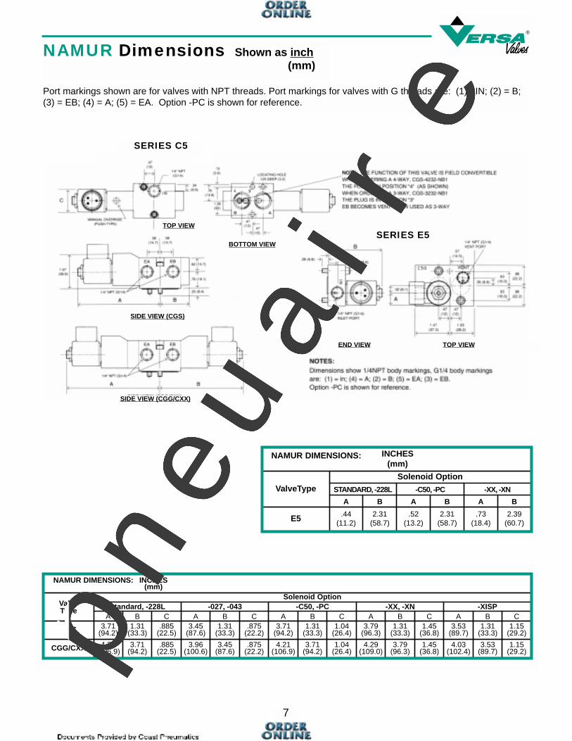
C
NAMUR DIMENSIONS: INCHES(mm)
ValveType
Solenoid Option
A
CGS 3.71(94.2)
CGG/CXX 4.21(106.9)
1.15(29.2)
1.31(33.3)
3.53(89.7)
1.45(36.8)
1.31(33.3)
3.79(96.3)
1.04(26.4)
1.31(33.3)
3.71(94.2)
.875(22.2)
1.31(33.3)
3.45(87.6)
.885(22.5)
1.31(33.3)
1.15(29.2)
3.53(89.7)
4.03(102.4)
1.45(36.8)
3.79(96.3)
4.29(109.0)
1.04(26.4)
3.71(94.2)
4.21(106.9)
.875(22.2)
3.45(87.6)
3.96(100.6)
.885(22.5)
3.71(94.2)
Standard, -228L -XISP-XX, -XN-C50, -PC-027, -043CBACBACBACBACB
Solenoid
NAMUR DIMENSIONS: INCHES(mm)
ValveType
E5 2.39(60.7)
.73(18.4)
2.31(58.7)
.52(13.2)
2.31(58.7)
.44(11.2)
-XX, -XN-C50, -PCSTANDARD, -228L
AAA
Solenoid Option
B B B
END VIEW TOP VIEW
SERIES C5
SERIES E5TOP VIEW
SIDE VIEW (CGS)
SIDE VIEW (CGG/CXX)
BOTTOM VIEW
NAMUR Dimensions Shown as inch(mm)
Port markings shown are for valves with NPT threads. Port markings for valves with G threads are: (1) =IN; (2) = B;(3) = EB; (4) = A; (5) = EA. Option -PC is shown for reference.pneu
air
e

General DescriptionVersa C5 and C7 valves are 5 port/2-position or 5 port/3-position, highflow, bodyported, solenoid/pilotvalves. They can be provided withsingle solenoid or double solenoidactuators. Manual override(guarded-push to operate, turn tolock) is standard on all models. Otheroptions are available. Actuator positioning ispossible with the use of 3-position valves since all C5and C7 valves are leakfree/bubbletight.
The Basic valve is supplied with DIN style coil, but otheroptions are available making the most exacting and demandingspecifications or applications easy to satisfy.
MaterialsValve body and plunger: anodized aluminum Actuating Caps: solenoid— anodized aluminum
spring cap—synthetic resinPilot Piston: synthetic resinValve seals: plunger and body— FKM (fluorocarbon)
pilot piston— NBR (nitrile)Screws: stainless steelSolenoid parts: sleeve, plunger & spring— 304 & 430F
stainless steelcoils—epoxy molded with 3 spade
terminals (std) or 2 or 3 wire leads (opt)coil cover (opt.-when applicable)—zinc chromate
coated steel
BODYPORTED VALVES
Porting SizeInlet, outlet and exhaust — 1/8 NPT or G1/8-Series C5
1/4 NPT or G1/4-Series C7
Installation, Filtration and LubricationValves have no limitations on mounting orientation. 40 to 50 micron filtration and general purpose lubricating oil ISO,ASTM viscosity grade 32 recommended.Ambient temperature range 5°F (15°C) to 125°F (50°C).
Flow Rates (average for all ports)
Cv = 0.75 (Kv = 11) for 1/8 NPT (G1/8)-Series C5Cv = 1.6 (Kv = 23) for 1/4 NPT (G1/4)-Series C7
Options SuffixManual Override: none Standard on basic valves,
guarded-push to operate, turn to lock-CML unguarded-push to operate,twist to lock
All other options see page 6 (same options utilized as DirectMount Valves).
† Pressure ranges maychange based on solenoid option. See page 6.
MPa = bar10
For higher pressure applications, consult factory.
C5/C7 Bodyported ValveProduct Number Selector
Basic Valve Number
FUNCTION* Cv (Kv)PORTSIZE
SIZESERIES
4-WAY5/2 & 5/3
C7
C5
1/4 NPTG1/4
1/8 NPTG1/8
SINGLE SOLENOID/SPRING RETURN, 2 POSITION
DOUBLE SOLENOID/SPRING CENTERED, 3 POSITIONDOUBLE SOLENOID/ DETENT, 2 POSITION
1.6 (23)1.6 (23)
0.75 (11)0.75 (11)
CSG-4322-†-(coil code)
CSG-4382-†-(coil code)
CSG-4222-†-(coil code)
CSG-4282-†-(coil code)
CGG-4322-†-(coil code)
CGG-4382-†-(coil code)
CGG-4222-†-(coil code)
CGG-4282-†-(coil code)
CXX-4323-†-(coil code)
CXX-4383-†-(coil code)
CXX-4223-†-(coil code)
CXX-4283-†-(coil code)
CXX-4324-†-(coil code)
CXX-4384-†-(coil code)
CXX-4224-†-(coil code)
CXX-4284-†-(coil code)
EB EA
B A
A
IN EB IN EA
B A
B A
EB IN EA
B A
B A
EB IN EA
B A
B A
Blocked Center Exhaust Ports Open
* 3-Way valve can be obtained by plugging one port of a 4-way. For 3-way NC plug port B (4); for 3-way NO plug port A (2).† Add suffix here, if required.
ALUMINUM CONSTRUCTION
For coil code see page 6.
Valve TypeSize
Series
Double Solenoid/spring centered(3-position)
Double Solenoid/detented(2-position)
Single Solenoid/spring return(2-position)
ApproximateWeights
OperatingPressure Range†
Pneumatic
C7
C5
C7
C5
C7
C5
25-115 psi(1.7-8 bar)
15-115 psi(1-8 bar)
15-115 psi(1-8 bar)
10-115 psi(0.7-8 bar)
25-115 psi(1.7-8 bar)
15-115 psi(1-8 bar)
1.0 lbs.(454 g)
0.87 lbs.(395 g)
1.0 lbs.(454 g)
0.87 lbs.(395 g)
0.7 lbs.(300 g)
0.5 lbs.(235 g)
OrdinaryService
1.3 lbs.(590 g)
1.2 lbs.(545 g)
1.3 lbs.(590 g)
1.2 lbs.(545 g)
1.0 lbs.(454 g)
0.8 lbs.(363 g)
HazardousService
SERIES C5/C7 Bodyported3-Way*/4-Way Solenoid Valves
8
pneu
air
e
9
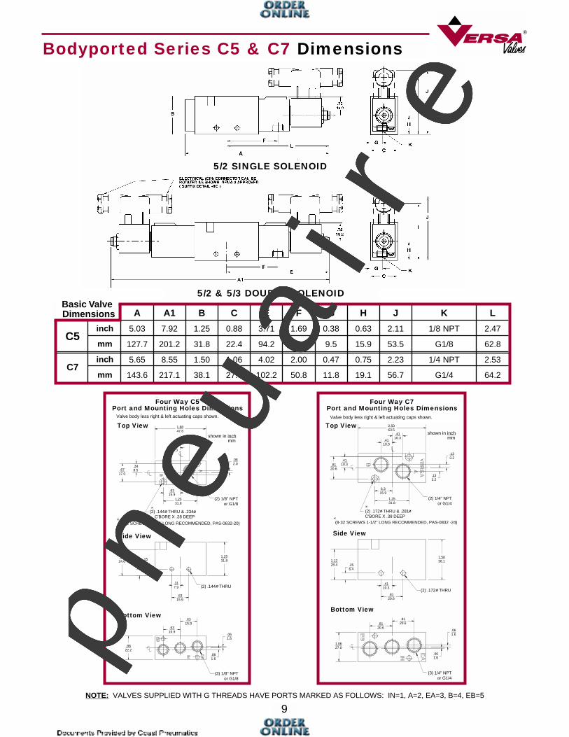
Bodyported Series C5 & C7 Dimensions
1.8847.6
.338.3
.338.3
.082.0
.082.0
.348.5.67
17.0
.6315.9
1.2531.8
(2) 1/8" NPTor G1/8
(6-32 SCREWS 1-1/4" LONG RECOMMENDED, PAS-0632-20)
(2) .144 THRU & .234 C'BORE X .28 DEEP
ø ø
(2) .144 THRUø
.9724.6
.256.4
.317.9
.6315.9
1.2531.8
.6315.9
.6315.9
.061.6
.061.6
.8822.2
(3) 1/8" NPTor G1/8
2.5063.5
.4110.3
.4110.3
.4110.3.81
20.6
.133.2
.133.2
6.315.9
1.2531.8
(2) .172 THRU & .281C'BORE X .38 DEEP
ø ø
(2) 1/4" NPTor G1/4
(8-32 SCREWS 1-1/2" LONG RECOMMENDED, PAS-0832 -24)
1.1228.4 .25
6.4
1.5038.1
(2) .172 THRU ø
.4110.3
.8120.6
.8120.6.81
20.6.061.6
.061.6
1.0627.0
(3) 1/4" NPTor G1/4
5/2 SINGLE SOLENOID
NOTE: VALVES SUPPLIED WITH G THREADS HAVE PORTS MARKED AS FOLLOWS: IN=1, A=2, EA=3, B=4, EB=5
Dimensions A A1 B C E F G H J K L
C5inch 5.03 7.92 1.25 0.88 3.71 1.69 0.38 0.63 2.11 1/8 NPT 2.47
mm 127.7 201.2 31.8 22.4 94.2 42.8 9.5 15.9 53.5 G1/8 62.8
C7inch 5.65 8.55 1.50 1.06 4.02 2.00 0.47 0.75 2.23 1/4 NPT 2.53
mm 143.6 217.1 38.1 27.0 102.2 50.8 11.8 19.1 56.7 G1/4 64.2
Basic Valve
Four Way C5Port and Mounting Holes Dimensions
Valve body less right & left actuating caps shown.
Top View
Four Way C7Port and Mounting Holes Dimensions
Valve body less right & left actuating caps shown.
Top Viewshown in inch
mm
shown in inchmm
5/2 & 5/3 DOUBLE SOLENOID
Side View
Bottom ViewBottom View
Side View
pneu
air
e
10
BODYPORTED VALVES
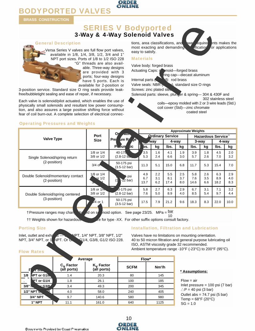
SERIES V Bodyported3-Way & 4-Way Solenoid Valves
General Description
Versa Series V valves are full flow port valves,available in 1/8, 1/4, 3/8, 1/2, 3/4 and 1”NPT port sizes. Ports of 1/8 to 1/2 ISO 228
“G” threads are also avail-able. Three-way designsare provided with 3ports; four-way designshave 5 ports. Each is
available for 2-position or3-position service. Standard size O ring seals provide leak-free/bubbletight sealing and ease of repair, if necessary.
Each valve is solenoid/pilot actuated, which enables the use ofphysically small solenoids and resultant low power consump-tion, and also assures a large positive shifting force withoutfear of coil burn-out. A complete selection of electrical connec-
tions, area classifications, and power requirements makes themost exacting and demanding specifications or applicationseasy to satisfy.
Materials
Valve body: forged brassActuating Caps: solenoid—forged brass
spring cap—diecast aluminumInternal parts (wetted): rod brassValve seals: NBR (nitrile), standard size O ringsScrews: zinc plated steelSolenoid parts: sleeve, plunger & spring— 304 & 430F and
302 stainless steelcoils—epoxy molded with 2 or 3 wire leads (Std.)coil cover (Std)—zinc chromate
coated steel
Porting Size
Inlet, outlet and exhaust — 1/8” NPT, 1/4” NPT, 3/8” NPT, 1/2”NPT, 3/4” NPT, or 1” NPT. Or G1/8, G1/4, G3/8, G1/2 ISO 228.
Flow Rates
Installation, Filtration and Lubrication
Valves have no limitations on mounting orientation. 40 to 50 micron filtration and general purpose lubricating oilISO, ASTM viscosity grade 32 recommended.Ambient temperature range -10°F (-23°C) to 200°F (95°C).
†Pressure ranges may change based on solenoid option. See page 23/25. MPa = bar10
†† Weights shown for hazardous service are for type -XX. For other suffix options consult factory.
Operating Pressures and Weights
Valve TypePortSize
Operating
Pressure Range†
Pneumatic
Approximate Weights
Single Solenoid/spring return(2-position)
1/8 or 1/43/8 or 1/2
40-175 psi(2.8-12 bar)
3/4 or 150-175 psi(3.5-12 bar)
Double Solenoid/momentary contact(2-position)
1/8 or 1/43/8 or 1/23/4 or 1
20-175 psi(1.4-12 bar)
Double Solenoid/spring centered(3-position)
1/8 or 1/43/8 or 1/2
40-175 psi(2.8-12 bar)
3/4 or 150-175 psi(3.5-12 bar) 17.5
5.87.6
4.96.7
13.7
11.3
3.55.3
lbs.
Ordinary Service
kg lbs. kg
5.87.6
14.6
11.7
3.95.7
lbs.
Hazardous Service††
kg lbs. kg
2.53.78.0
5.58.1
17.4
2.23.16.2
2.94.08.3
6.38.9
18.2
2.63.56.6
1.93.0
4.16.6
1.62.4
6.815.05.1
2.03.2
4.57.0
1.82.6
7.015.45.3
3.24.4
7.19.7
3.15.4
6.78.5
2.94.0
6.38.9
2.75.0
10.022.08.318.39.621.27.9
3-way 4-way 3-way 4-way
Port Size
Flow*
1” NPT
3/4” NPT
1/2” NPT or G1/2
3/8” NPT or G3/8
1/4” NPT or G1/4
1/8” NPT or G1/8
11.1
9.7
4.0
3.4
1.8
1.4
161.0
140.6
58.0
49.3
26.1
20.3
Average
640
580
240
200
100
80
SCFM
1125
980
405
345
185
145
Nm3/hCv Factor(all ports)
Kv Factor(all ports) * Assumptions:
Flow = airInlet pressure = 100 psi (7 bar)▲▲P = 40 psi (3 bar)Outlet abs = 74.7 psi (5 bar)Temp = 68°F (20°C)SG = 1.0
BRASS CONSTRUCTION
pneu
air
e
11
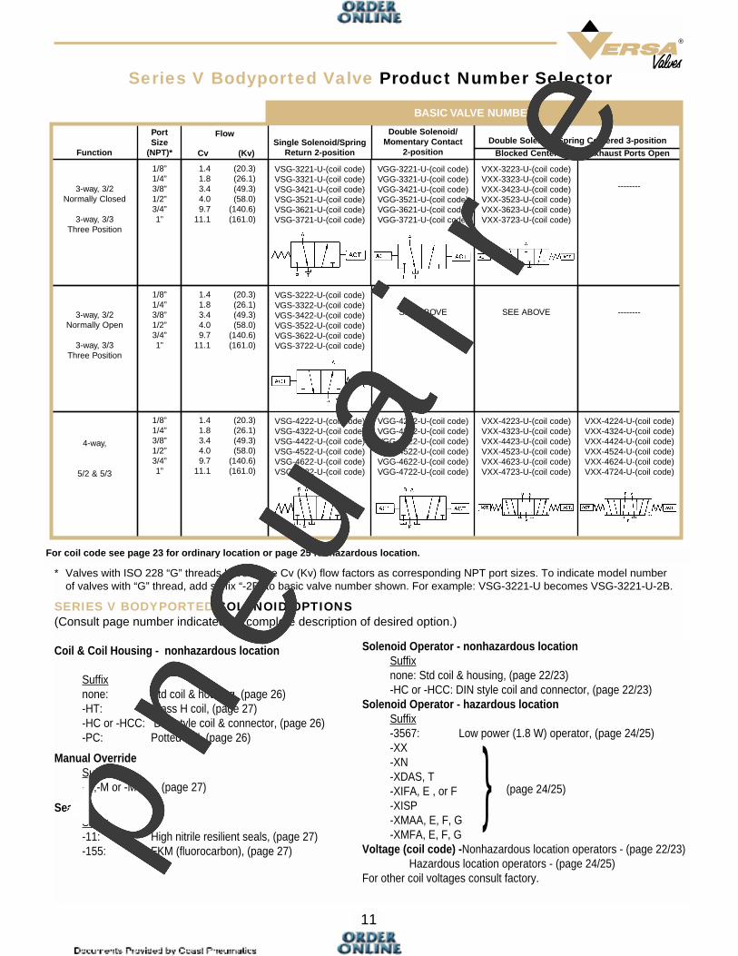
Series V Bodyported Valve Product Number Selector
VSG-4222-U-(coil code)VSG-4322-U-(coil code)VSG-4422-U-(coil code)VSG-4522-U-(coil code)VSG-4622-U-(coil code)VSG-4722-U-(coil code)
VGS-3222-U-(coil code)VGS-3322-U-(coil code)VGS-3422-U-(coil code)VGS-3522-U-(coil code)VGS-3622-U-(coil code)VGS-3722-U-(coil code)
VSG-3221-U-(coil code)VSG-3321-U-(coil code)VSG-3421-U-(coil code)VSG-3521-U-(coil code)VSG-3621-U-(coil code)VSG-3721-U-(coil code)
Single Solenoid/SpringReturn 2-position
VGG-4222-U-(coil code)VGG-4322-U-(coil code)VGG-4422-U-(coil code)VGG-4522-U-(coil code)VGG-4622-U-(coil code)VGG-4722-U-(coil code)
SEE ABOVE
VGG-3221-U-(coil code)VGG-3321-U-(coil code)VGG-3421-U-(coil code)VGG-3521-U-(coil code)VGG-3621-U-(coil code)VGG-3721-U-(coil code)
Double Solenoid/Momentary Contact
2-position
VXX-4223-U-(coil code)VXX-4323-U-(coil code)VXX-4423-U-(coil code)VXX-4523-U-(coil code)VXX-4623-U-(coil code)VXX-4723-U-(coil code)
SEE ABOVE
VXX-3223-U-(coil code)VXX-3323-U-(coil code)VXX-3423-U-(coil code)VXX-3523-U-(coil code)VXX-3623-U-(coil code)VXX-3723-U-(coil code)
Double Solenoid/Spring Centered 3-position
VXX-4224-U-(coil code)VXX-4324-U-(coil code)VXX-4424-U-(coil code)VXX-4524-U-(coil code)VXX-4624-U-(coil code)VXX-4724-U-(coil code)
--------
--------
4-way,
5/2 & 5/3
3-way, 3/2Normally Open
3-way, 3/3Three Position
3-way, 3/2Normally Closed
3-way, 3/3Three Position
Function
1/8”1/4”3/8”1/2”3/4”1”
1/8”1/4”3/8”1/2”3/4”1”
1/8”1/4”3/8”1/2”3/4”1”
PortSize
(NPT)*
1.4 (20.3)1.8 (26.1)3.4 (49.3)4.0 (58.0)9.7 (140.6)
11.1 (161.0)
1.4 (20.3)1.8 (26.1)3.4 (49.3)4.0 (58.0)9.7 (140.6)
11.1 (161.0)
1.4 (20.3)1.8 (26.1)3.4 (49.3)4.0 (58.0)9.7 (140.6)
11.1 (161.0)
Flow
Blocked Center Exhaust Ports OpenCv (Kv)
BASIC VALVE NUMBER
* Valves with ISO 228 “G” threads have same Cv (Kv) flow factors as corresponding NPT port sizes. To indicate model number of valves with “G” thread, add suffix “-2B” to basic valve number shown. For example: VSG-3221-U becomes VSG-3221-U-2B.
SERIES V BODYPORTED SOLENOID OPTIONS(Consult page number indicated for complete description of desired option.)
Coil & Coil Housing - nonhazardous location
Suffixnone: Std coil & housing, (page 26)-HT: Class H coil, (page 27)-HC or -HCC: DIN style coil & connector, (page 26)-PC: Potted coil, (page 26)
Manual OverrideSuffix-G,-M or -M5R: (page 27)
SealsSuffix-11: High nitrile resilient seals, (page 27)-155: FKM (fluorocarbon), (page 27)
Solenoid Operator - nonhazardous locationSuffixnone: Std coil & housing, (page 22/23)-HC or -HCC: DIN style coil and connector, (page 22/23)
Solenoid Operator - hazardous locationSuffix-3567: Low power (1.8 W) operator, (page 24/25)-XX-XN-XDAS, T-XIFA, E , or F-XISP-XMAA, E, F, G-XMFA, E, F, G
Voltage (coil code) -Nonhazardous location operators - (page 22/23)Hazardous location operators - (page 24/25)
For other coil voltages consult factory.
} (page 24/25)
For coil code see page 23 for ordinary location or page 25 for hazardous location.
pneu
air
e
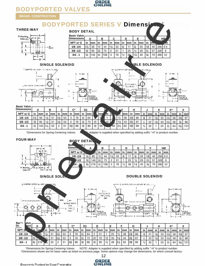
A B C D E F HØ
NPT or G in mm in mm in mm in mm in mm in mm in mm
1/8 -1/4 2��� 56 1 44 1��� 33 ���� 17 ��� 20 1���� 40 .256 6.5
3/8 -1/2 3 95 2�� 73 2 51 1 25 1�� 29 2� 57 .328 8
3/4 - 1 5�� 140 4� 108 3 76 1�� 38 1��� 40 3�� 79 .390 10
A B C C* D1 D E F H
NPT or G in mm in mm in mm in mm in mm in mm in mm in mm in mm
1/8 -1/4 3�� 89 1��� 31 2��� 53 3 76 2�� 64 2 51 1 25 1�� 38 2���� 66
3/8 -1/2 5 146 1��� 31 2��� 53 3 76 2�� 73 2 70 1� 35 1���� 43 2���� 67
3/4 - 1 8�� 216 2��� 52 2 51 3���� 88 3� 86 3 95 1�� 48 2��� 62 3���� 99
12
BODYPORTED SERIES V Dimensions†
THREE-WAY
FOUR-WAY
BODYPORTED VALVESBRASS CONSTRUCTION
SINGLE SOLENOID DOUBLE SOLENOID
BODY DETAIL
J K K* X
in mm in mm in mm in mm
��� 21 1��� 33 2��� 56 3��� 97
�� 22 1��� 33 2��� 56 3�� 98
1� 32 1 25 2�� 64 5��� 131
A B C C* D1 D E F H
NPT or G in mm in mm in mm in mm in mm in mm in mm in mm in mm
1/8 -1/4 2��� 56 1��� 31 2��� 53 3 76 2�� 64 2 51 1 25 1�� 38 2���� 66
3/8 -1/2 3 95 1��� 31 2��� 53 3 76 2�� 73 2 70 1� 35 1���� 43 2���� 67
3/4 - 1 5�� 140 2��� 52 2 51 3���� 88 3� 86 3 95 1�� 48 2��� 62 3���� 99
J K K* X
in mm in mm in mm in mm
��� 21 1��� 33 2��� 56 3��� 97
�� 22 1��� 33 2��� 56 3�� 98
1� 32 1 25 2�� 64 5��� 131
BODY DETAIL
SINGLE SOLENOID DOUBLE SOLENOID
*Dimensions for Spring-Centering Valves. NOTE: Adapter is supplied when specified by adding suffix "-H" to product number.
*Dimensions for Spring-Centering Valves. NOTE: Adapter is supplied when specified by adding suffix "-H" to product number.†Dimensions shown are for basic valve as listed on previous page. Some options may change the dimensions, for which consult factory.
Basic ValveDimensions
A B C D E F HØ
NPT or G in mm in mm in mm in mm in mm in mm in mm
1/8 -1/4 3�� 89 1 44 1��� 33 ���� 17 ��� 20 1���� 40 .256 6.5
3/8 -1/2 5 146 2�� 73 2 51 1 25 1�� 29 2� 57 .328 8
3/4 - 1 8�� 216 4� 108 3 76 1�� 38 1��� 40 3�� 79 .390 10
Basic ValveDimensions
Basic ValveDimensions
Basic ValveDimensions
pneu
air
e
3-WAY DIRECT SOLENOID OPTIONS (Consult page number indicated for complete description of desired option.)
Series E SOLENOID OPERATOR – Series E5Suffix (nonhazardous location) Suffix
-HC or -HCC: DIN style coil & -HC or -HCCconnector, (page 22/23)
-PC: Potted coil, (page 26) -PC
SOLENOID OPERATOR -(hazardous location)
----------- -LB-XX; -LB-XN-XDAS or T -----------XX -XX----------- Flameproof (page 24/25) -XN-PS-XX -PC-XX
-XMAA, E, F or G ------------XMFA, E, F or G Encapsulation (page 24/25) -----------
-XIFA, E or FIntrinsically Safe
(page 24/25) -XISP
MISCELLANEOUS
-3 FKM (fluorocarbon) seals (Page 27) -3-HT Class H coil (page 27) -HT-M,-M5R,-MAE Manual Override (page 27) -----------
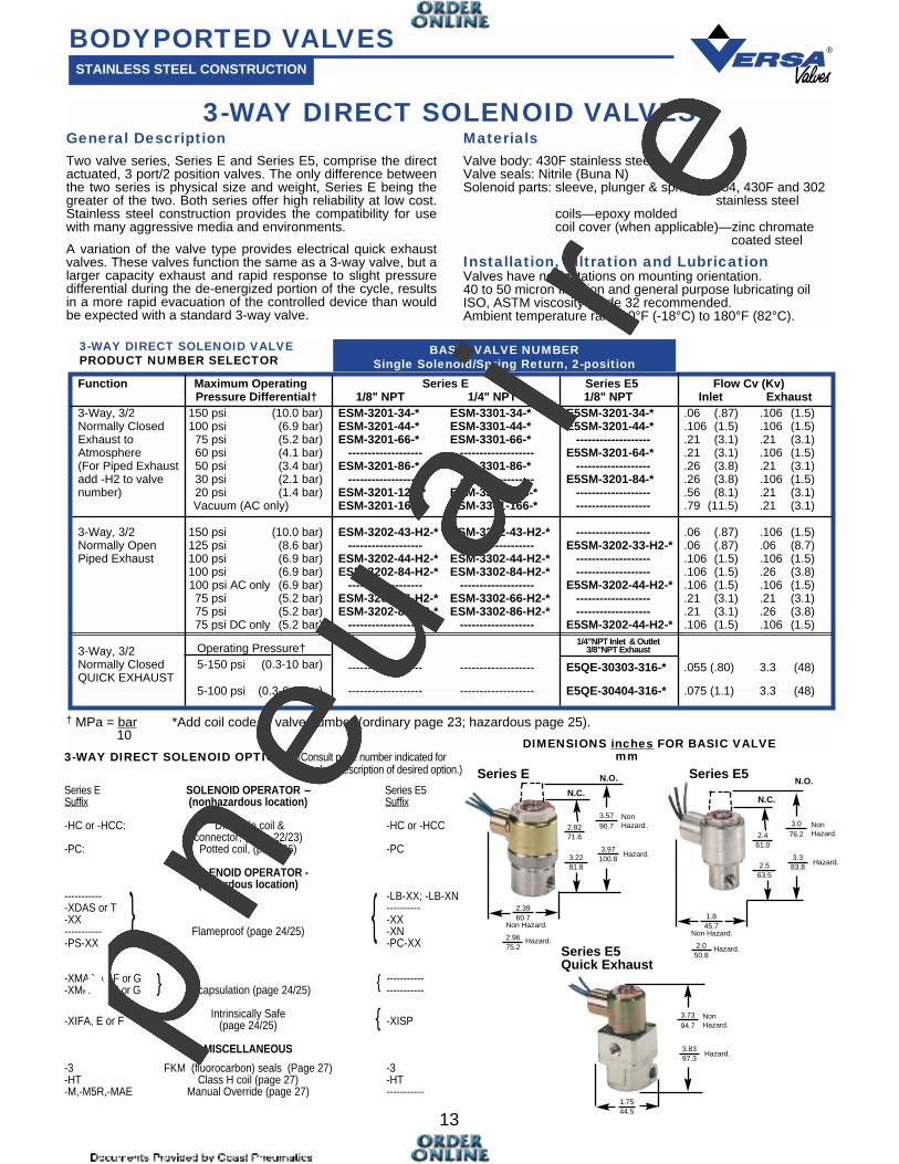
Function Maximum Operating Series E Series E5 Flow Cv (Kv)Pressure Differential† 1/8" NPT 1/4" NPT 1/8" NPT Inlet Exhaust
3-Way, 3/2 150 psi (10.0 bar) ESM-3201-34-* ESM-3301-34-* E5SM-3201-34-* .06 (.87) .106 (1.5)Normally Closed 100 psi (6.9 bar) ESM-3201-44-* ESM-3301-44-* E5SM-3201-44-* .106 (1.5) .106 (1.5)Exhaust to 75 psi (5.2 bar) ESM-3201-66-* ESM-3301-66-* ------------------- .21 (3.1) .21 (3.1)Atmosphere 60 psi (4.1 bar) ------------------- ------------------- E5SM-3201-64-* .21 (3.1) .106 (1.5)(For Piped Exhaust 50 psi (3.4 bar) ESM-3201-86-* ESM-3301-86-* ------------------- .26 (3.8) .21 (3.1)add -H2 to valve 30 psi (2.1 bar) ------------------- ------------------- E5SM-3201-84-* .26 (3.8) .106 (1.5)number) 20 psi (1.4 bar) ESM-3201-126-* ESM-3301-126-* ------------------- .56 (8.1) .21 (3.1)
Vacuum (AC only) ESM-3201-166-* ESM-3301-166-* ------------------- .79 (11.5) .21 (3.1)
3-Way, 3/2 150 psi (10.0 bar) ESM-3202-43-H2-* ESM-3302-43-H2-* ------------------- .06 (.87) .106 (1.5)Normally Open 125 psi (8.6 bar) ------------------- ------------------- E5SM-3202-33-H2-* .06 (.87) .06 (8.7)Piped Exhaust 100 psi (6.9 bar) ESM-3202-44-H2-* ESM-3302-44-H2-* ------------------- .106 (1.5) .106 (1.5)
100 psi (6.9 bar) ESM-3202-84-H2-* ESM-3302-84-H2-* ------------------- .106 (1.5) .26 (3.8)100 psi AC only (6.9 bar) ------------------- ------------------- E5SM-3202-44-H2-* .106 (1.5) .106 (1.5)75 psi (5.2 bar) ESM-3202-66-H2-* ESM-3302-66-H2-* ------------------- .21 (3.1) .21 (3.1)75 psi (5.2 bar) ESM-3202-86-H2-* ESM-3302-86-H2-* ------------------- .21 (3.1) .26 (3.8)75 psi DC only (5.2 bar) ------------------- ------------------- E5SM-3202-44-H2-* .106 (1.5) .106 (1.5)
3-Way, 3/2 Operating Pressure†Normally Closed 5-150 psi (0.3-10 bar) ------------------- ------------------- E5QE-30303-316-* .055 (.80) 3.3 (48)QUICK EXHAUST
5-100 psi (0.3-6.9 bar) ------------------- ------------------- E5QE-30404-316-* .075 (1.1) 3.3 (48)
13
3-WAY DIRECT SOLENOID VALVESGeneral DescriptionTwo valve series, Series E and Series E5, comprise the directactuated, 3 port/2 position valves. The only difference betweenthe two series is physical size and weight, Series E being thegreater of the two. Both series offer high reliability at low cost.Stainless steel construction provides the compatibility for usewith many aggressive media and environments.
A variation of the valve type provides electrical quick exhaustvalves. These valves function the same as a 3-way valve, but alarger capacity exhaust and rapid response to slight pressuredifferential during the de-energized portion of the cycle, resultsin a more rapid evacuation of the controlled device than wouldbe expected with a standard 3-way valve.
MaterialsValve body: 430F stainless steelValve seals: Nitrile (Buna N)Solenoid parts: sleeve, plunger & spring— 304, 430F and 302
stainless steelcoils—epoxy moldedcoil cover (when applicable)—zinc chromate
coated steel
Installation, Filtration and LubricationValves have no limitations on mounting orientation. 40 to 50 micron filtration and general purpose lubricating oilISO, ASTM viscosity grade 32 recommended.Ambient temperature range 0°F (-18°C) to 180°F (82°C).
† MPa = bar *Add coil code to valve number (ordinary page 23; hazardous page 25).10
BODYPORTED VALVESSTAINLESS STEEL CONSTRUCTION
}
} }
}}
1/4”NPT Inlet & Outlet3/8”NPT Exhaust
BASIC VALVE NUMBERSingle Solenoid/Spring Return, 2-position
3-WAY DIRECT SOLENOID VALVEPRODUCT NUMBER SELECTOR
DIMENSIONS inches FOR BASIC VALVEmm
}
Series E N.O. Series E5N.O.
Series E5Quick Exhaust
2.8271.6
3.57 90.7
3.22 81.8
3.97 100.8
2.39 60.7
2.96 75.2
Hazard.
Non Hazard.
NonHazard.
Hazard.
2.461.0
3.0 76.2
2.5 63.5
3.383.8
1.845.7
2.0 50.8
Hazard.
Non Hazard.
NonHazard.
Hazard.
N.C.N.C.
1.7544.5
3.73 94.7
3.83 97.3
NonHazard.
Hazard.pneu
air
e
Operating Pressures and Weights
Valve Type Port SizeOperating
Pressure Range†
Pneumatic
Single Solenoid/spring return(2-position)
1/4” & 3/8” NPT1/2” NPT
40-175 psi(2.8-12 bar)
2.53.4
lbs. kg lbs. kg lbs. kg lbs. kg
3.55.0
3.44.3
1.51.6
3.23.6
1.21.6
2.73.6
1.31.5
2.83.2
1.21.6
2.02.1
4.34.7
1.72.1
3.84.7
1.82.0
3.94.3
1.62.0
2.02.5
4.45.4
1.82.5
3.95.4
1.82.3
4.05.0
1.62.3
40-175 psi(2.8-12 bar)
20-175 psi(1.4-12 bar)
1/4” & 3/8” NPT1/2” NPT
1/4” & 3/8” NPT1/2” NPT
Double Solenoid/spring centered(3-position)
Double Solenoid/momentary contact(2-position)
Approximate Weights
3-way 4-way3-way4-wayOrdinary Service Hazardous Service††
14
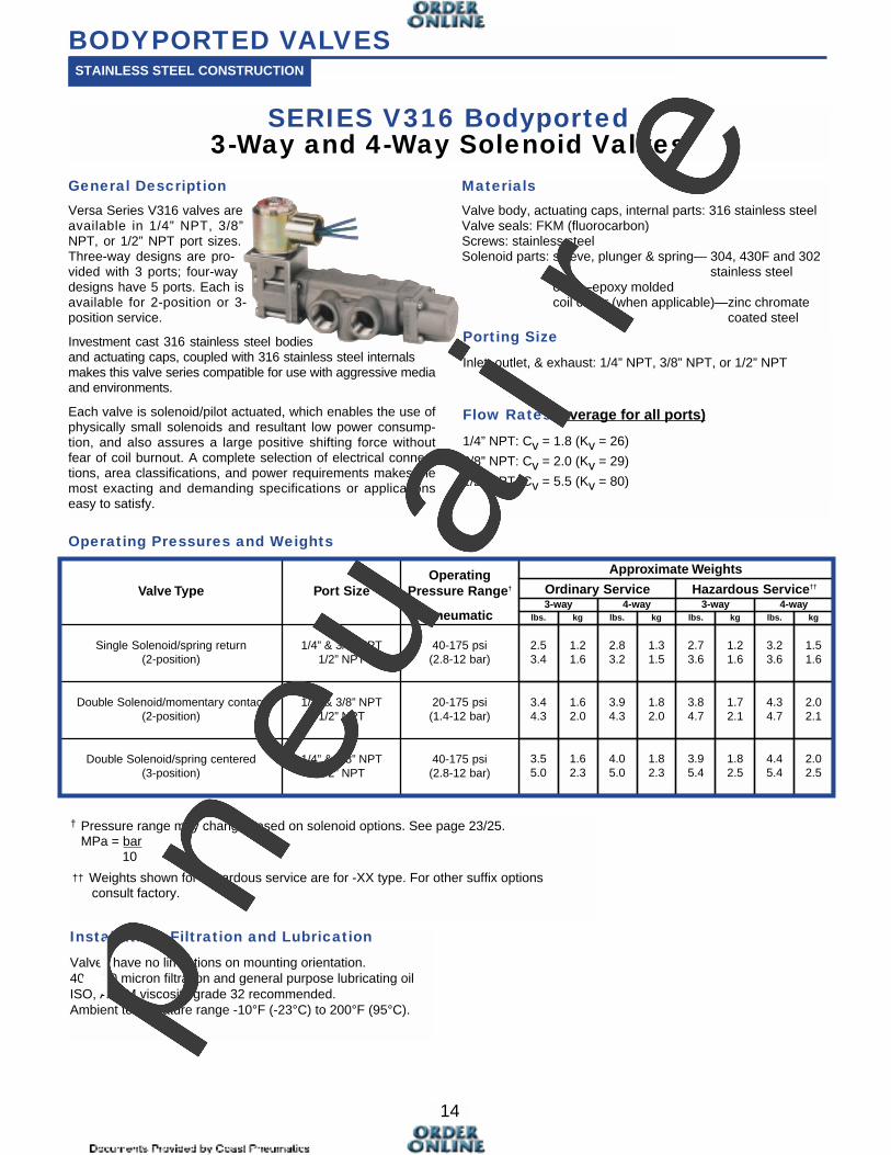
SERIES V316 Bodyported3-Way and 4-Way Solenoid Valves
General Description
Versa Series V316 valves areavailable in 1/4” NPT, 3/8”NPT, or 1/2” NPT port sizes.Three-way designs are pro-vided with 3 ports; four-waydesigns have 5 ports. Each isavailable for 2-position or 3-position service.
Investment cast 316 stainless steel bodiesand actuating caps, coupled with 316 stainless steel internalsmakes this valve series compatible for use with aggressive mediaand environments.
Each valve is solenoid/pilot actuated, which enables the use ofphysically small solenoids and resultant low power consump-tion, and also assures a large positive shifting force withoutfear of coil burnout. A complete selection of electrical connec-tions, area classifications, and power requirements makes themost exacting and demanding specifications or applicationseasy to satisfy.
Materials
Valve body, actuating caps, internal parts: 316 stainless steelValve seals: FKM (fluorocarbon)Screws: stainless steelSolenoid parts: sleeve, plunger & spring— 304, 430F and 302
stainless steelcoils—epoxy moldedcoil cover (when applicable)—zinc chromate
coated steel
Porting Size
Inlet, outlet, & exhaust: 1/4” NPT, 3/8” NPT, or 1/2” NPT
Flow Rates (average for all ports)
1/4” NPT: Cv = 1.8 (Kv = 26)
3/8” NPT: Cv = 2.0 (Kv = 29)
1/2” NPT: Cv = 5.5 (Kv = 80)
† Pressure range may change based on solenoid options. See page 23/25. MPa = bar
10
†† Weights shown for hazardous service are for -XX type. For other suffix options consult factory.
BODYPORTED VALVESSTAINLESS STEEL CONSTRUCTION
Installation, Filtration and Lubrication
Valves have no limitations on mounting orientation. 40 to 50 micron filtration and general purpose lubricating oilISO, ASTM viscosity grade 32 recommended.Ambient temperature range -10°F (-23°C) to 200°F (95°C).pneu
air
e
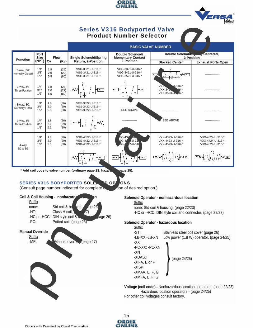
3-way, 3/2Normally Closed
3-Way, 3/3Three-Position
VSG-3321-U-316-*VSG-3421-U-316-*VSG-3521-U-316-*
VGG-3321-U-316-*VGG-3421-U-316-*VGG-3521-U-316-*
---------------
VXX-3323-U-316-*VXX-3423-U-316-*VXX-3523-U-316-*
---------------
3-way, 3/2Normally Open
3-Way, 3/3Three-Position
VGS-3322-U-316-*VGS-3422-U-316-*VGS-3522-U-316-* SEE ABOVE
---------------
---------------
SEE ABOVE
---------------
---------------
4-Way5/2 & 5/3
VSG-4322-U-316-*VSG-4422-U-316-*VSG-4522-U-316-*
VGG-4322-U-316-*VGG-4422-U-316-*VGG-4522-U-316-*
VXX-4323-U-316-*VXX-4423-U-316-*VXX-4523-U-316-*
VXX-4324-U-316-*VXX-4424-U-316-*VXX-4524-U-316-*
1.8 (26)2.0 (29)5.5 (80)
1.8 (26)2.0 (29)5.5 (80)
1/4”3/8”1/2”
1/4”3/8”1/2”
1.8 (26)2.0 (29)5.5 (80)
1.8 (26)2.0 (29)5.5 (80)
1/4”3/8”1/2”
1/4”3/8”1/2”
1.8 (26)2.0 (29)5.5 (80)
1/4”3/8”1/2”
Exhaust Ports OpenBlocked Center
Double Solenoid/Spring Centered,3-Position
Double Solenoid/Momentary Contact
2-PositionSingle Solenoid/Spring
Return, 2-PositionFlow
Cv (Kv)
PortSize
(NPT)Function
BASIC VALVE NUMBER
15
Series V316 Bodyported ValveProduct Number Selector
* Add coil code to valve number (ordinary page 23; hazardous page 25).
SERIES V316 BODYPORTED SOLENOID OPTIONS (Consult page number indicated for complete description of desired option.)
Coil & Coil Housing - nonhazardous locationSuffixnone: Std coil & housing, (page 26)-HT: Class H coil, (page 27)-HC or -HCC: DIN style coil & connector, (page 26)-PC: Potted coil, (page 26)
Manual OverrideSuffix-ME: Manual override (page 27)
Solenoid Operator - nonhazardous locationSuffixnone: Std coil & housing, (page 22/23)-HC or -HCC: DIN style coil and connector, (page 22/23)
Solenoid Operator - hazardous locationSuffix-ST: Stainless steel coil cover (page 26)-LB-XX;-LB-XN Low power (1.8 W) operator, (page 24/25)-XX-PC-XX; -PC-XN-XN-XDAS,T-XIFA, E or F-XISP-XMAA, E, F, G-XMFA, E, F, G
Voltage (coil code) - Nonhazardous location operators - (page 22/23)Hazardous location operators - (page 24/25)
For other coil voltages consult factory.
} (page 24/25)
pneu
air
e
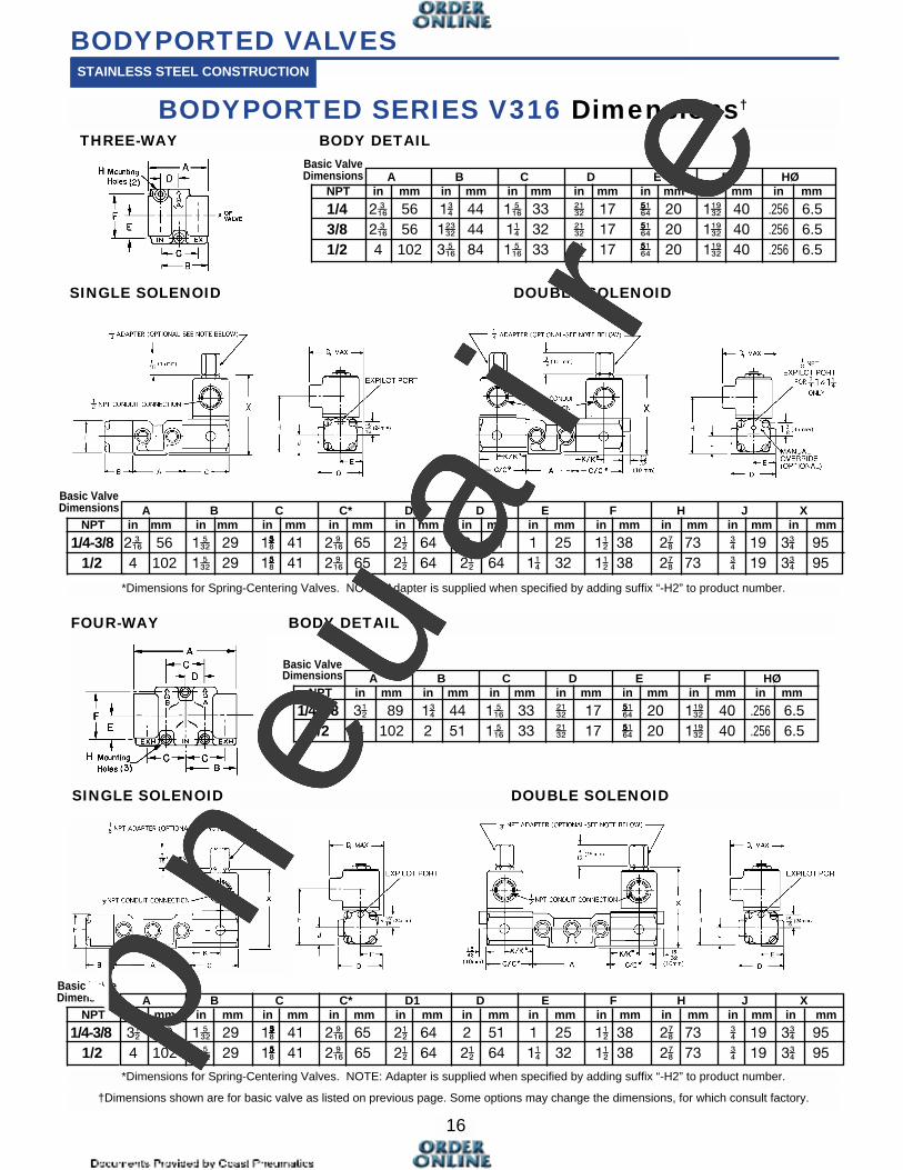
A B C C* D1 D E F H J XNPT in mm in mm in mm in mm in mm in mm in mm in mm in mm in mm in mm
1/4-3/8 3�� 89 1��� 29 1���� 41 2��� 65 2�� 64 2 51 1 25 1�� 38 2�� 73 19 3 95
1/2 4 102 1��� 29 1���� 41 2��� 65 2�� 64 2�� 64 1� 32 1�� 38 2�� 73 19 3 95
A B C D E F HØNPT in mm in mm in mm in mm in mm in mm in mm
1/4-3/8 3�� 89 1 44 1��� 33 ���� 17 ����� 20 1���� 40 .256 6.51/2 4 102 2 51 1��� 33 ���� 17 ����� 20 1���� 40 .256 6.5
A B C C* D1 D E F H J XNPT in mm in mm in mm in mm in mm in mm in mm in mm in mm in mm in mm
1/4-3/8 2��� 56 1��� 29 1��� 41 2��� 65 2�� 64 2 51 1 25 1�� 38 2�� 73 19 3 95
1/2 4 102 1��� 29 1��� 41 2��� 65 2�� 64 2�� 64 1� 32 1�� 38 2�� 73 19 3 95
A B C D E F HØNPT in mm in mm in mm in mm in mm in mm in mm
1/4 2��� 56 1 44 1��� 33 ���� 17 ����� 20 1���� 40 .256 6.53/8 2��� 56 1��� 44 1� 32 ���� 17 ����� 20 1���� 40 .256 6.51/2 4 102 3��� 84 1��� 33 ���� 17 ����� 20 1���� 40 .256 6.5
16
BODYPORTED SERIES V316 Dimensions†
THREE-WAY BODY DETAIL
FOUR-WAY BODY DETAIL
BODYPORTED VALVESSTAINLESS STEEL CONSTRUCTION
SINGLE SOLENOID DOUBLE SOLENOID
SINGLE SOLENOID DOUBLE SOLENOID
†Dimensions shown are for basic valve as listed on previous page. Some options may change the dimensions, for which consult factory.
*Dimensions for Spring-Centering Valves. NOTE: Adapter is supplied when specified by adding suffix “-H2” to product number.
*Dimensions for Spring-Centering Valves. NOTE: Adapter is supplied when specified by adding suffix “-H2” to product number.
Basic ValveDimensions
Basic ValveDimensions
Basic ValveDimensions
Basic ValveDimensions
pneu
air
e
17
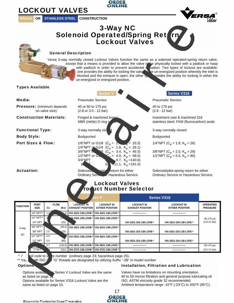
3-Way NCSolenoid Operated/Spring Return
Lockout Valves
®
Versa 3-way normally closed Lockout Valves function the same as a solenoid operated-spring return valve,except that a means is provided to allow the valve to be physically locked with a padlock or hasp
with padlock in order to prevent accidental actuation. Two types of lockout are available:one provides the ability for locking the valve in the un-energized position whereby the inlet isblocked and the exhaust is open; the other type provides the ability for locking in either the
un-energized or energized position.
LOCKOUT VALVES
LOCKOUT INEITHER POSITIONFUNCTION
PORTSIZE
FLOWCv (Kv)
LOCKOUT INEXHAUST POSITION
LOCKOUT INEITHER POSITION
LOCKOUT INEXHAUST POSITION
OPERATINGPRESSURE
3-way
NC
1/8” NPT** 1.4 (20.3) VIA-3221-138-LOVB-* VIA-3221-138-LOVE-* ---------------- ----------------
40-175 psi(2.8-12 bar)
1/4” NPT**
1/4” NPT
1.8 (26.1)
1.8 (26)
VIA-3321-138-LOVB-* VIA-3321-138-LOVE-*
VIA-3321-316-138-LOVB-* VIA-3321-316-138-LOVE-*
3/8” NPT**
3/8” NPT
3.4 (49.3)
2.0 (29)
VIA-3421-138-LOVB-* VIA-3421-138-LOVE-*
VIA-3421-316-138-LOVB-* VIA-3421-316-138-LOVE-*
1/2” NPT**
1/2” NPT
4.0 (58)
5.5 (80)
VIA-3521-138-LOVB-* VIA-3521-138-LOVE-*
VIA-3521-316-138-LOVB-* VIA-3521-316-138-LOVE-*
3/4” NPT 9.7 (140.6) VIA-3621-138-LOVB-* VIA-3621-138-LOVE-* ---------------- ---------------- 50-175 psi
(3.5-12 bar)1” NPT 11.1 (161) VIA-3721-138-LOVB-* VIA-3721-138-LOVE-* ---------------- ----------------
Series V316Series V
Options
Options available for Series V Lockout Valve are the sameas listed on page 11.Options available for Series V316 Lockout Valve are thesame as listed on page 15.
Installation, Filtration and Lubrication
Valves have no limitations on mounting orientation. 40 to 50 micron filtration and general purpose lubricating oilISO, ASTM viscosity grade 32 recommended.Ambient temperature range -10°F (-23°C) to 200°F (95°C).
* Add coil code to valve number (ordinary page 23; hazardous page 25).** Valves with ISO 228 “G” threads are designated by utilizing Suffix “-2B” in model number
General Description
Lockout ValvesProduct Number Selector
BRASS STAINLESS STEELOR CONSTRUCTION
Types Available
Series V Series V316
Media: Pneumatic Service Pneumatic Service
Pressure: (minimum depends 40 or 50 to 175 psi 40 to 175 psion valve size) (2.8 or 3.5 - 12 bar) (2.8 - 12 bar)
Construction Materials: Forged & machined brass; Investment cast & machined 316NBR (nitrile) O ring seals stainless steel; FKM (fluorocarbon) seals
Functional Type: 3-way normally closed 3-way normally closed
Body Style: Bodyported Bodyported
Port Sizes & Flow: 1/8”NPT or G1/8 (Cv = 1.4, Kv = 20.3) 1/4”NPT (Cv = 1.8, Kv = 26)1/4”NPT or G1/4 (Cv = 1.8, Kv = 26.1)3/8”NPT or G3/8 (Cv = 3.4, Kv = 49.3) 3/8”NPT (Cv = 2.0, Kv = 29)1/2”NPT or G1/2 (Cv = 4.0, Kv = 58.0) 1/2”NPT (Cv = 5.5, Kv = 80)3/4”NPT (Cv = 9.7, Kv =140.6)
1”NPT (Cv = 11.1, Kv =161.0)
Actuation: Solenoid/pilot-spring return for either Solenoid/pilot-spring return for eitherOrdinary Service or Hazardous Service. Ordinary Service or Hazardous Service.
pneu
air
e

Media Pneumatic; others, consult factory. Pneumatic and various other gases, including corrosives.
Pressure: (minimum depends 20 or 55 to 175 psi 20 or 55 to 175 psi on size and type) (1.4 or 3.8 to 12 bar) (1.4 or 3.8 to 12 bar)
Construction Materials Forged & machined brass; Investment cast & machined 316NBR (nitrile) O ring seals stainless steel; FKM (fluorocarbon) seals
Functional Type 3-way normally closed 3-way normally closed3-way normally open 3-way normally open3-way 3-position 3-way 3-position4-way 2 & 3 position 4-way 2 & 3 position
Body Style Bodyported Bodyported
Port Sizes & Flow 1/8”NPT or G1/8 (Cv = 1.4, Kv = 20.3) 1/4”NPT (Cv = 1.8, Kv = 26)1/4”NPT or G1/4 (Cv = 1.8, Kv = 26.1)3/8”NPT or G3/8 (Cv = 3.4, Kv = 49.3) 3/8”NPT (Cv = 2.0, Kv = 29)1/2”NPT or G1/2 (Cv = 4.0, Kv = 58.0) 1/2”NPT (Cv = 5.5, Kv = 80)3/4”NPT (Cv = 9.7, Kv = 140.6)
1”NPT (Cv =11.1, Kv = 161.0)
Actuation Solenoid/pilot for either ordinary service or Solenoid/pilot for either ordinary service or hazardous service. hazardous service.
LATCHES IN ACTUATED POSITIONSeries V, Suffix “-181B”Series V316, Suffix “-181BE” Latches automatically when
plunger shifts on signal. Un-latching allows plunger to be returned by hand.
18
Latching valves are particularly suited to applications where it is desirable or mandatory tomanually reset or restart a system. A typical application could involve the emergency shut-down of automatically monitored process operations. Loss or interruption of the control sig-nal to the valve actuator causes the valve to shift, latch and shut-down a process step.When the signal is restored the valve remains in the latched position until the operatormanually unlatches it and allows the process step to resume. Positive latching in such anapplication is vitally important since many process operations are sequential and one step mustnot be started until the one ahead of it has started.
This example is only one of many which can be accommodated through the use of Versa’s Latching Valves. A widerange of functional types, port sizes, actuators, and latching arrangements provide the engineer with a complete choice ofvalving to suit his particular needs.
LATCHING/MANUAL RESET VALVES
General Description
Types Available
Latching/Reset Devices For Series V or V316 ValvesThe Latching Device actuator consists of the latch, with or without an integral spring for returningthe valve plunger, and an inline hand operator where needed to manually shift the valve.
The specific Latching Device may be attached to any Series “V” valve body size or style up to 1” NPTor any Series V316 valve body up to 1/2” NPT, as indicated for the type of latching/reset devicerequired. The actuator on the opposite end of the valve body would be a solenoid/pilot device.
LATCHES IN UNACTUATED POSITIONSeries V, Suffix “-181D”Series V316, Suffix “-181DE” Unlatching allows plunger to shift
on signal. If signal is lost, spring shifts plunger automatically and valve latches. When signal is restored, plunger will not shift until manually unlatched. Hand lever is provided for manual operation. (If hand lever is not required see suffix -3358 or -3358E below.)
LATCHES IN EITHER POSITIONSeries V, Suffix “-181AA”Series V316, Suffix “-181AAE” (2 position latch) Valve may be
manually latched in either offsetposition or left unlatched. Acts as spring return valve when not latched. Hand lever is provided for hand operation.
Series V, Suffix “-181C”Series V316, Suffix “-181CE” Latches automatically when plun-
ger shifts on signal. Unlatching allows spring to reset plunger automatically. Hand lever provid-ed for manual operation. (If hand lever is not required see suffix -3358A or -3358AE below.)
Series V, Suffix “-3358A”Series V316, Suffix “-3358AE” Latches automatically when
plunger shifts on signal. Un-latching allows spring to reset plunger automatically. (If hand lever is required for manual actuation see suffix -181C or -181CE above.)
Series V, Suffix “-3358”Series V316, Suffix “-3358E” Unlatching allows plunger to shift
on signal. Spring returns plunger automatically and valve latches. (If hand lever is required for man-ual actuation see suffix -181D or -181DE above.)
BRASS STAINLESS STEELOR CONSTRUCTION
Series V Series V316
pneu
air
e

V = Pneumatic service: nominal 20 to 175 psi (1.4 - 12 bar); pressure range may vary depending upon specific valve type. See page 10 for Series V, page 14 for Series V316.
AG=Solenoid/pilot operated (NEMA 1,2,3) for 3-way NC or 4-way
GA=Solenoid/pilot operated (NEMA 1,2,3) for 3-way NO
3 = Three-way4 = Four-way
2 = 1/8”NPT (Series V*)3 = 1/4”NPT (Series V* or V316)4 = 3/8”NPT (Series V* or V316)5 = 1/2”NPT (Series V* or V316)6 = 3/4”NPT (Series V)7 = 1”NPT (Series V)
2 = Threaded sideports-INPilot solenoid: no auxilliary pilot required.
1 = 3-way NC2 = 3-way NO, 4-way/2-position3 = 4-way/3-position (blocked center)4 = 4-way/3-position (exhaust ports open in center)
LOCKING/RESET DEVICE Series V Series V316(refer to page 18 for 181AA 316-181AAEspecific device required) 181B 316-181BE
181C 316-181CE181D 316-181DE3358 316-3358E3358A 316-3358AE
OPTIONS (Refer to pages 22 to 27 for specific certifications, standards & classifications, approvals, and protective codes.)Series V Series V316
Electrical Connection/ -HC -HCCoil Cover -HCC -HCC
Seals -11 ------155 -----
Solenoids for Hazardous Service -XX -XX-XN -XN
Flameproof-XDAS,T -XDAS,T-3567 -LB-XX-LB-XN -LB-XN-XMAA, E, F, G -XMAA, E, F, G Encapsulation-XMFA, E, F, G -XMFA, E, F, G -XISP -XISP-XIFA, E or F -XIFA, E or F Intrinsically safe
-3 ------PS -PC
Options for Special Conditions-HT -HT -HT-G,-M,-M5R -ME-TR50-ST -ST
Voltage (coil code) } See page 23 for ordinary location and page 25 for hazardous location.
Series V Series V316
}19
®
How to specify LATCHING/RESET VALVESV AG - 3 5 2 1 - 181B - (OPTIONS)
}}
}
}}
}
}}}
}
}
*Valves with ISO 228 “G” Threads are designated by utilizing suffix “-2B“ in model number.Installation, Filtration and Lubrication Valves have no limitations on mounting orientation. 40 to 50 micron filtration and general purposelubricating oil ISO, ASTM viscosity grade 32 recommended. Ambient temperature range -10°F (-23°C) to 200°F (95°C).
}
Series V Series V316
}
pneu
air
e
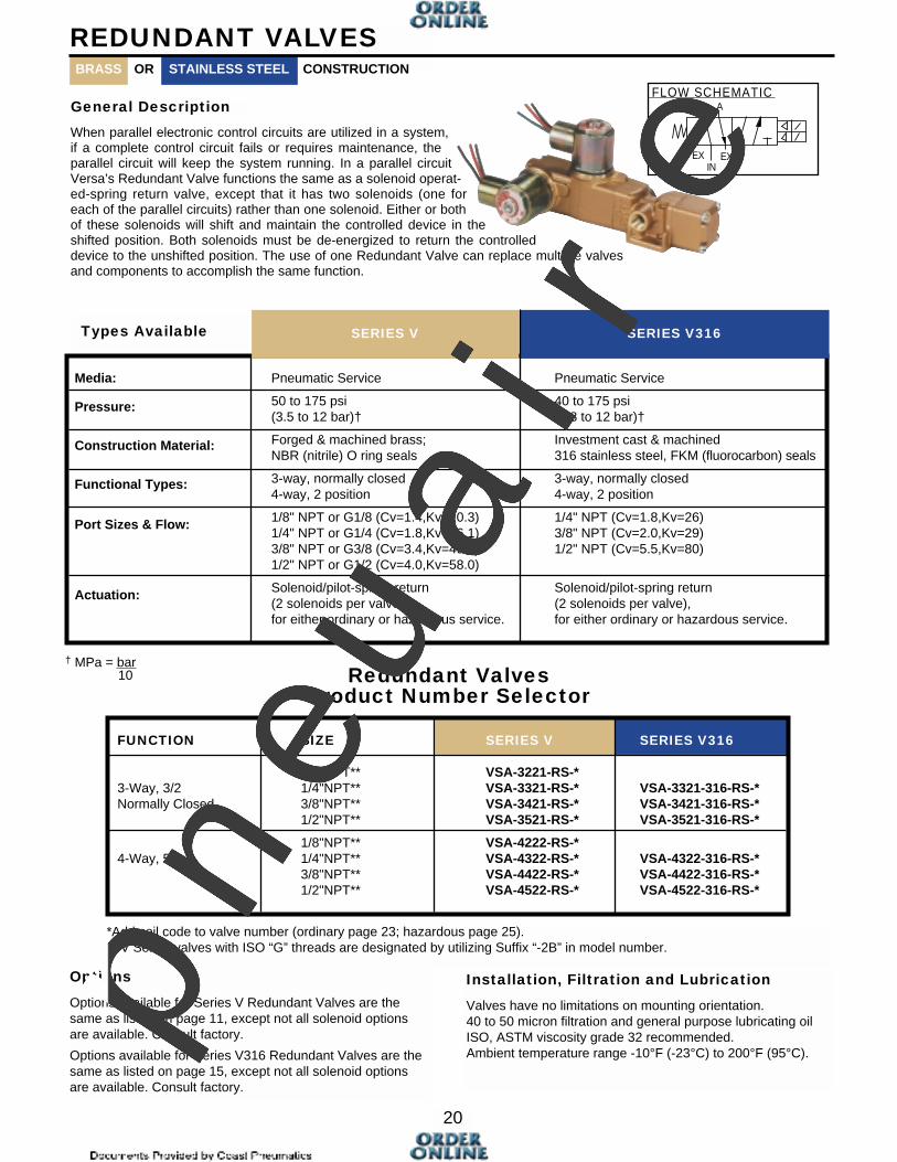
Media: Pneumatic Service Pneumatic Service
Pressure: 50 to 175 psi 40 to 175 psi(3.5 to 12 bar)† (2.8 to 12 bar)†
Construction Material: Forged & machined brass; Investment cast & machinedNBR (nitrile) O ring seals 316 stainless steel, FKM (fluorocarbon) seals
Functional Types: 3-way, normally closed 3-way, normally closed4-way, 2 position 4-way, 2 position
Port Sizes & Flow: 1/8" NPT or G1/8 (Cv=1.4,Kv=20.3) 1/4" NPT (Cv=1.8,Kv=26)1/4" NPT or G1/4 (Cv=1.8,Kv=26.1) 3/8" NPT (Cv=2.0,Kv=29)3/8" NPT or G3/8 (Cv=3.4,Kv=49.3) 1/2" NPT (Cv=5.5,Kv=80)1/2" NPT or G1/2 (Cv=4.0,Kv=58.0)
Actuation: Solenoid/pilot-spring return Solenoid/pilot-spring return(2 solenoids per valve), (2 solenoids per valve),for either ordinary or hazardous service. for either ordinary or hazardous service.
20
REDUNDANT VALVES
When parallel electronic control circuits are utilized in a system,if a complete control circuit fails or requires maintenance, theparallel circuit will keep the system running. In a parallel circuitVersa’s Redundant Valve functions the same as a solenoid operat-ed-spring return valve, except that it has two solenoids (one foreach of the parallel circuits) rather than one solenoid. Either or bothof these solenoids will shift and maintain the controlled device in theshifted position. Both solenoids must be de-energized to return the controlleddevice to the unshifted position. The use of one Redundant Valve can replace multiple valvesand components to accomplish the same function.
General Description
Redundant ValvesProduct Number Selector
Types Available
† MPa = bar10
*Add coil code to valve number (ordinary page 23; hazardous page 25).** V Series valves with ISO “G” threads are designated by utilizing Suffix “-2B” in model number.
Installation, Filtration and Lubrication
Valves have no limitations on mounting orientation. 40 to 50 micron filtration and general purpose lubricating oilISO, ASTM viscosity grade 32 recommended.Ambient temperature range -10°F (-23°C) to 200°F (95°C).
Options
Options available for Series V Redundant Valves are thesame as listed on page 11, except not all solenoid optionsare available. Consult factory.
Options available for Series V316 Redundant Valves are thesame as listed on page 15, except not all solenoid optionsare available. Consult factory.
FLOW SCHEMATICB A
INEX EX
BRASS STAINLESS STEELOR CONSTRUCTION
FUNCTION SIZE SERIES V SERIES V316
1/8"NPT** VSA-3221-RS-*3-Way, 3/2 1/4"NPT** VSA-3321-RS-* VSA-3321-316-RS-*Normally Closed 3/8"NPT** VSA-3421-RS-* VSA-3421-316-RS-*
1/2"NPT** VSA-3521-RS-* VSA-3521-316-RS-*
1/8"NPT** VSA-4222-RS-*4-Way, 5/2 1/4"NPT** VSA-4322-RS-* VSA-4322-316-RS-*
3/8"NPT** VSA-4422-RS-* VSA-4422-316-RS-*1/2"NPT** VSA-4522-RS-* VSA-4522-316-RS-*
SERIES V SERIES V316
pneu
air
e
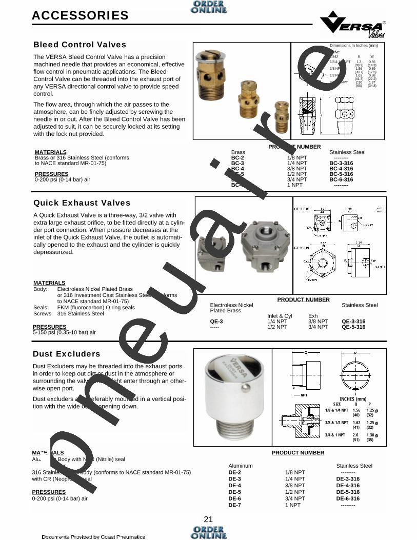
MATERIALS PRODUCT NUMBERAluminum Body with NBR (Nitrile) seal
or Aluminum Stainless Steel316 Stainless Steel body (conforms to NACE standard MR-01-75) DE-2 1/8 NPT --------with CR (Neoprene) seal DE-3 1/4 NPT DE-3-316
DE-4 3/8 NPT DE-4-316PRESSURES DE-5 1/2 NPT DE-5-3160-200 psi (0-14 bar) air DE-6 3/4 NPT DE-6-316
DE-7 1 NPT --------
PRODUCT NUMBERElectroless Nickel Stainless SteelPlated Brass
Inlet & Cyl ExhQE-3 1/4 NPT 3/8 NPT QE-3-316
PRESSURES ----- 1/2 NPT 3/4 NPT QE-5-3165-150 psi (0.35-10 bar) air
21
®
Bleed Control ValvesThe VERSA Bleed Control Valve has a precisionmachined needle that provides an economical, effectiveflow control in pneumatic applications. The BleedControl Valve can be threaded into the exhaust port ofany VERSA directional control valve to provide speedcontrol.
The flow area, through which the air passes to theatmosphere, can be finely adjusted by screwing theneedle in or out. After the Bleed Control Valve has beenadjusted to suit, it can be securely locked at its settingwith the lock nut provided.
ACCESSORIES
Quick Exhaust ValvesA Quick Exhaust Valve is a three-way, 3/2 valve withextra large exhaust orifice, to be fitted directly at a cylin-der port connection. When pressure decreases at theinlet of the Quick Exhaust Valve, the outlet is automati-cally opened to the exhaust and the cylinder is quicklydepressurized.
MATERIALSBody: Electroless Nickel Plated Brass
or 316 Investment Cast Stainless Steel (conformsto NACE standard MR-01-75)
Seals: FKM (fluorocarbon) O ring sealsScrews: 316 Stainless Steel
Dust ExcludersDust Excluders may be threaded into the exhaust portsin order to keep out dirt or dust in the atmosphere orsurrounding the valve, that might enter through an other-wise open port.
Dust excluders are preferably mounted in a vertical posi-tion with the wide outlet opening down.
PRODUCT NUMBERMATERIALS Brass Stainless SteelBrass or 316 Stainless Steel (conforms BC-2 1/8 NPT --------to NACE standard MR-01-75) BC-3 1/4 NPT BC-3-316
BC-4 3/8 NPT BC-4-316PRESSURES BC-5 1/2 NPT BC-5-3160-200 psi (0-14 bar) air BC-6 3/4 NPT BC-6-316
BC-7 1 NPT --------
Dimensions In Inches (mm)
ValveTHD H W
1/8 & 1/4 NPT 1.3 0.56(33.3) (14.3)
3/8 NPT 1.56 0.69(39.7) (17.5)
1/2 NPT 1.63 0.88(41.3) (22.2)
3/4 & 1 NPT 2.36 1.37(60) (34.8)
INCHES (mm)SIZE Q P
1/8 & 1/4 NPT 1.56 1.25 ø(40) (32)
3/8 & 1/2 NPT 1.62 1.25 ø(41) (32)
3/4 & 1 NPT 2.0 1.38 ø(51) (35)p
neu
air
e
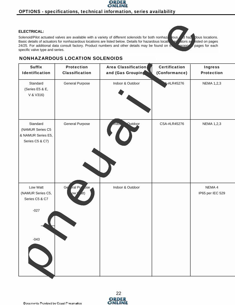
Suffix Protection Area Classification Certification IngressIdentification Classification and (Gas Grouping) (Conformance) Protection
Standard General Purpose Indoor & Outdoor CSA-#LR45276 NEMA 1,2,3
(Series E5 & E,
V & V316)
Standard General Purpose Indoor & Outdoor CSA-#LR45276 NEMA 1,2,3
(NAMUR Series C5
& NAMUR Series E5,
Series C5 & C7)
Low Watt General Purpose Indoor & Outdoor NEMA 4
(NAMUR Series C5, (Low Watt) IP65 per IEC 529
Series C5 & C7
-027
-043
22
OPTIONS - specifications, technical information, series availability
ELECTRICAL:Solenoid/Pilot actuated valves are available with a variety of different solenoids for both nonhazardous and hazardous locations.Basic details of actuators for nonhazardous locations are listed below. Details for hazardous location actuators are listed on pages24/25. For additional data consult factory. Product numbers and other details may be found on the appropriate pages for eachspecific valve type and series.
NONHAZARDOUS LOCATION SOLENOIDS
pneu
air
e
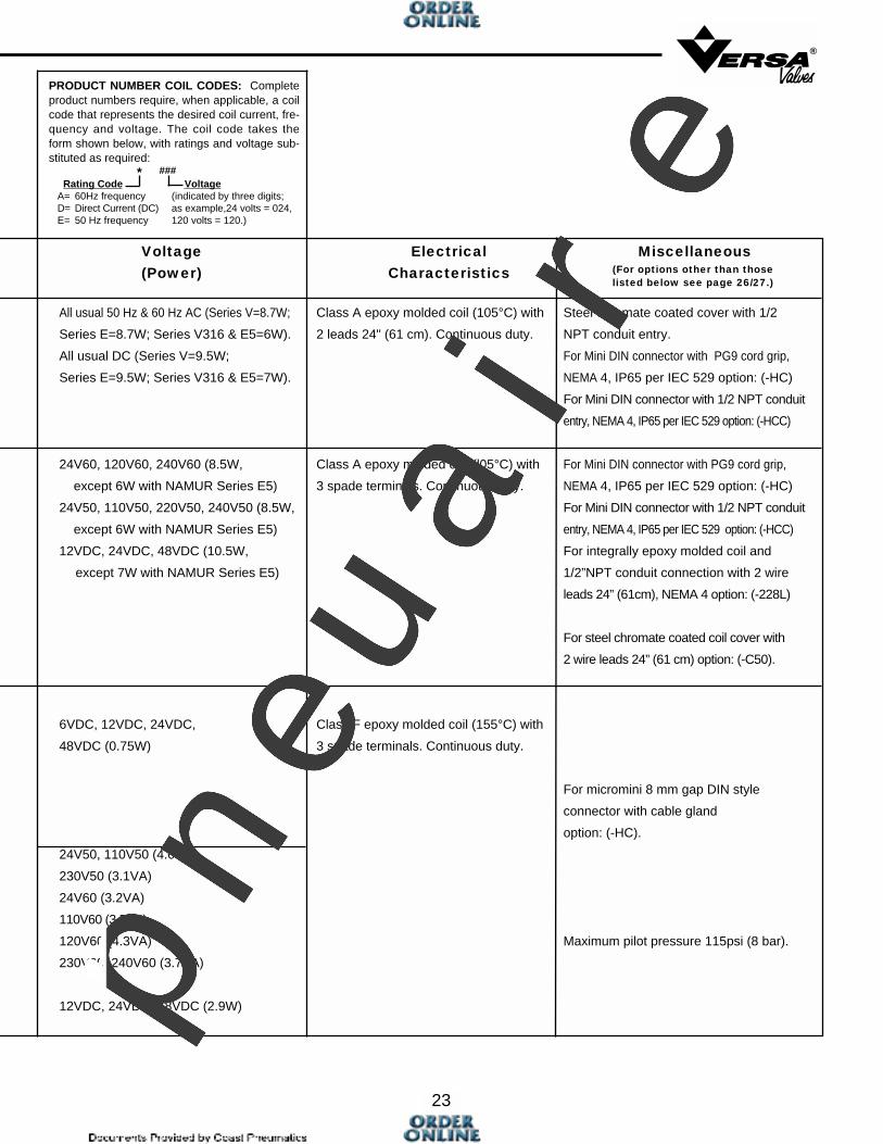
Voltage Electrical Miscellaneous(Power) Characteristics
All usual 50 Hz & 60 Hz AC (Series V=8.7W; Class A epoxy molded coil (105°C) with Steel chromate coated cover with 1/2
Series E=8.7W; Series V316 & E5=6W). 2 leads 24" (61 cm). Continuous duty. NPT conduit entry.
All usual DC (Series V=9.5W; For Mini DIN connector with PG9 cord grip,
Series E=9.5W; Series V316 & E5=7W). NEMA 4, IP65 per IEC 529 option: (-HC)
For Mini DIN connector with 1/2 NPT conduit
entry, NEMA 4, IP65 per IEC 529 option: (-HCC)
24V60, 120V60, 240V60 (8.5W, Class A epoxy molded coil (l05°C) with For Mini DIN connector with PG9 cord grip,
except 6W with NAMUR Series E5) 3 spade terminals. Continuous duty. NEMA 4, IP65 per IEC 529 option: (-HC)
24V50, 110V50, 220V50, 240V50 (8.5W, For Mini DIN connector with 1/2 NPT conduit
except 6W with NAMUR Series E5) entry, NEMA 4, IP65 per IEC 529 option: (-HCC)
12VDC, 24VDC, 48VDC (10.5W, For integrally epoxy molded coil and
except 7W with NAMUR Series E5) 1/2”NPT conduit connection with 2 wire
leads 24” (61cm), NEMA 4 option: (-228L)
For steel chromate coated coil cover with
2 wire leads 24” (61 cm) option: (-C50).
6VDC, 12VDC, 24VDC, Class F epoxy molded coil (155°C) with
48VDC (0.75W) 3 spade terminals. Continuous duty.
For micromini 8 mm gap DIN style
connector with cable gland
option: (-HC).
24V50, 110V50 (4.0VA)
230V50 (3.1VA)
24V60 (3.2VA)
110V60 (3.5VA)
120V60 (4.3VA) Maximum pilot pressure 115psi (8 bar).
230V60, 240V60 (3.7VA)
12VDC, 24VDC, 48VDC (2.9W)
23
®
(For options other than thoselisted below see page 26/27.)
PRODUCT NUMBER COIL CODES: Completeproduct numbers require, when applicable, a coilcode that represents the desired coil current, fre-quency and voltage. The coil code takes theform shown below, with ratings and voltage sub-stituted as required:
* ###Rating Code Voltage
A= 60Hz frequency (indicated by three digits; D= Direct Current (DC) as example,24 volts = 024, E= 50 Hz frequency 120 volts = 120.)
pneu
air
e
Suffix Protection Area Classification Certification IngressIdentification Classification and (Gas Grouping) (Conformance) Protection
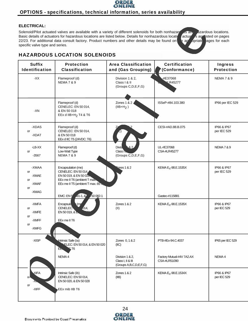
-XX Flameproof (d) Division 1 & 2, UL-#E37068 NEMA 7 & 9NEMA 7 & 9 Class I & II CSA-#LR45277
(Groups C,D,E,F,G)
Flameproof (d) Zones 1 & 2 ISSeP-#84.103.380 IP66 per IEC 529CENELEC: EN 50 014, (IIB+H2 )
-XN & EN 50 018 EEx d IIB+H2 T4 & T6
-XDAS Flameproof (d) Zones 1 & 2 CESI-#AD.88.B.075 IP66 & IP67 or CENELEC: EN 50 014, (IIC) per IEC 529
-XDAT & EN 50 018EEx d IIC T5 (24VDC: T6)
-LB-XX Flameproof (d) Division 1 & 2, UL-#E37068 NEMA 7 & 9or Low-Watt Type Class I & II CSA-#LR45277
-3567 NEMA 7 & 9 (Groups C,D,E,F,G)
-XMAA Encapsulation (me) Zones 1 & 2 KEMA EX-98.E.1535X IP66 & IP67or CENELEC: EN 50 014, (II) per IEC 529
-XMAE EN 50 019, & EN 50 028or EEx me II T6 (ambient T max. 50°C)
-XMAF EEx me II T5 (ambient T max. 65°C)or
-XMAGEMC: EN 50 081-1, & EN 50 082-1 Gastec-#115881
-XMFA Encapsulation (me) Zones 1 & 2 KEMA EX-98.E.1535X IP66 & IP67 or CENELEC: EN 50 014, (II) per IEC 529
-XMFE EN 50 019, & EN 50 028or
-XMFF EEx me II T6or
-XMFG
-XISP Intrinsic Safe (ia) Zones 0, 1 & 2 PTB-#Ex-94.C.4037 IP65 per IEC 529CENELEC: EN 50 014, & EN 50 020 (IIC)EEx ia IIC T6
NEMA 4 Division 1 & 2, Factory Mutual-#4V 7A2.AX NEMA 4Class I, II & III CSA-#LR51090(Groups A,B,C,D,E,F,G)
-XIFA Intrinsic Safe (ib) Zones 1 & 2 KEMA EX-98.E.1534X IP66 & IP67 or CENELEC: EN 50 014, (IIB) per IEC 529
-XIFE EN 50 020, & EN 50 028or
-XIFF EEx mib IIB T6
24
OPTIONS - specifications, technical information, series availability
ELECTRICAL:Solenoid/Pilot actuated valves are available with a variety of different solenoids for both nonhazardous and hazardous locations.Basic details of actuators for hazardous locations are listed below. Details for nonhazardous location actuators are listed on pages22/23. For additional data consult factory. Product numbers and other details may be found on the appropriate pages for eachspecific valve type and series.
HAZARDOUS LOCATION SOLENOIDS
pneu
air
e
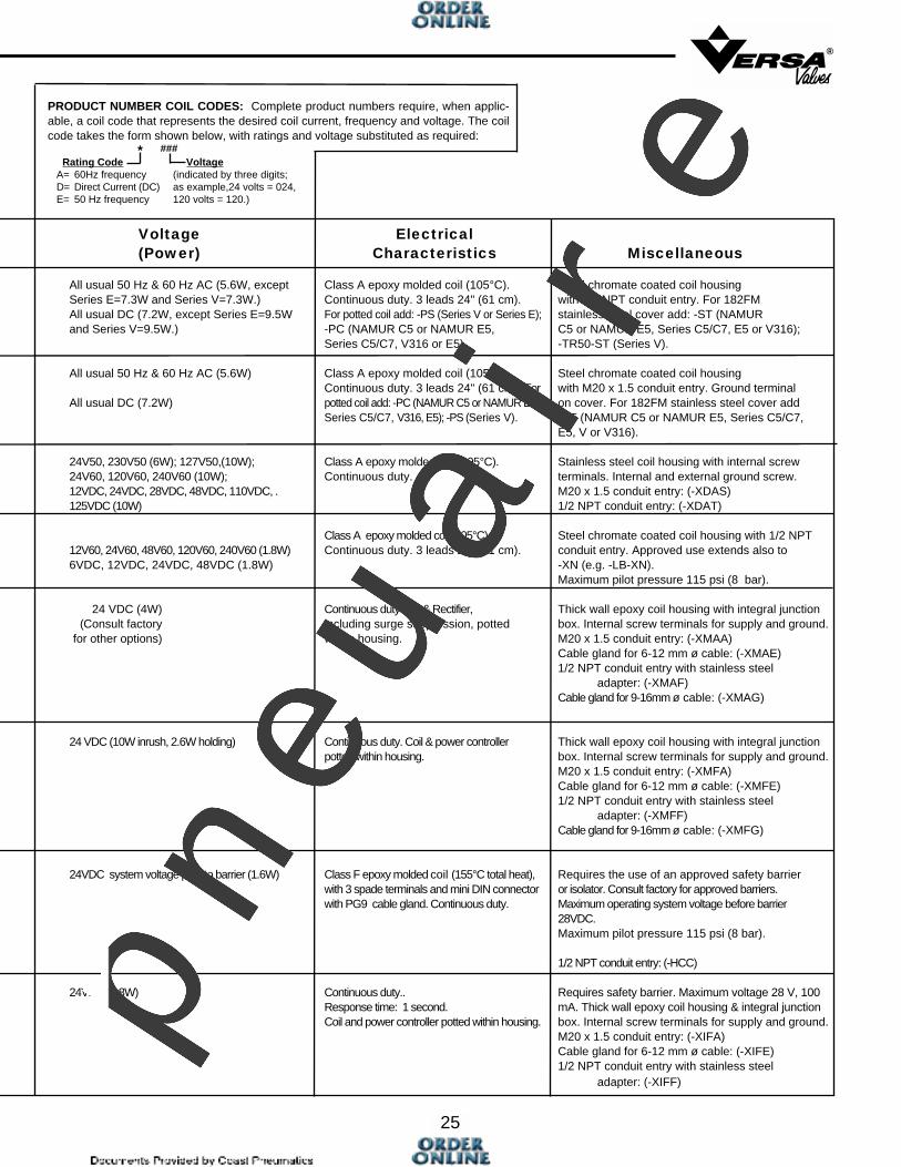
Voltage Electrical(Power) Characteristics Miscellaneous
All usual 50 Hz & 60 Hz AC (5.6W, except Class A epoxy molded coil (105°C). Steel chromate coated coil housing Series E=7.3W and Series V=7.3W.) Continuous duty. 3 leads 24" (61 cm). with 1/2 NPT conduit entry. For 182FMAll usual DC (7.2W, except Series E=9.5W For potted coil add: -PS (Series V or Series E); stainless steel cover add: -ST (NAMURand Series V=9.5W.) -PC (NAMUR C5 or NAMUR E5, C5 or NAMUR E5, Series C5/C7, E5 or V316);
Series C5/C7, V316 or E5). -TR50-ST (Series V).
All usual 50 Hz & 60 Hz AC (5.6W) Class A epoxy molded coil (105°C). Steel chromate coated coil housing Continuous duty. 3 leads 24" (61 cm). For with M20 x 1.5 conduit entry. Ground terminal
All usual DC (7.2W) potted coil add: -PC (NAMUR C5 or NAMUR E5, on cover. For 182FM stainless steel cover addSeries C5/C7, V316, E5); -PS (Series V). -ST (NAMUR C5 or NAMUR E5, Series C5/C7,
E5, V or V316).
24V50, 230V50 (6W); 127V50,(10W); Class A epoxy molded coil (105°C). Stainless steel coil housing with internal screw24V60, 120V60, 240V60 (10W); Continuous duty. terminals. Internal and external ground screw.12VDC, 24VDC, 28VDC, 48VDC, 110VDC, . M20 x 1.5 conduit entry: (-XDAS)125VDC (10W) 1/2 NPT conduit entry: (-XDAT)
Class A epoxy molded coil (105°C). Steel chromate coated coil housing with 1/2 NPT12V60, 24V60, 48V60, 120V60, 240V60 (1.8W) Continuous duty. 3 leads 24" (61 cm). conduit entry. Approved use extends also to6VDC, 12VDC, 24VDC, 48VDC (1.8W) -XN (e.g. -LB-XN).
Maximum pilot pressure 115 psi (8 bar).
24 VDC (4W) Continuous duty Coil & Rectifier, Thick wall epoxy coil housing with integral junction(Consult factory including surge suppression, potted box. Internal screw terminals for supply and ground.
for other options) within housing. M20 x 1.5 conduit entry: (-XMAA)Cable gland for 6-12 mm ø cable: (-XMAE)1/2 NPT conduit entry with stainless steel
adapter: (-XMAF)Cable gland for 9-16mm ø cable: (-XMAG)
24 VDC (10W inrush, 2.6W holding) Continuous duty. Coil & power controller Thick wall epoxy coil housing with integral junctionpotted within housing. box. Internal screw terminals for supply and ground.
M20 x 1.5 conduit entry: (-XMFA)Cable gland for 6-12 mm ø cable: (-XMFE)1/2 NPT conduit entry with stainless steel
adapter: (-XMFF)Cable gland for 9-16mm ø cable: (-XMFG)
24VDC system voltage prior to barrier (1.6W) Class F epoxy molded coil (155°C total heat), Requires the use of an approved safety barrier with 3 spade terminals and mini DIN connector or isolator. Consult factory for approved barriers.with PG9 cable gland. Continuous duty. Maximum operating system voltage before barrier
28VDC.Maximum pilot pressure 115 psi (8 bar).
1/2 NPT conduit entry: (-HCC)
24VDC (0.8W) Continuous duty.. Requires safety barrier. Maximum voltage 28 V, 100Response time: 1 second. mA. Thick wall epoxy coil housing & integral junctionCoil and power controller potted within housing. box. Internal screw terminals for supply and ground.
M20 x 1.5 conduit entry: (-XIFA)Cable gland for 6-12 mm ø cable: (-XIFE)1/2 NPT conduit entry with stainless steel
adapter: (-XIFF)
25
®
PRODUCT NUMBER COIL CODES: Complete product numbers require, when applic-able, a coil code that represents the desired coil current, frequency and voltage. The coilcode takes the form shown below, with ratings and voltage substituted as required:
* ###Rating Code Voltage
A= 60Hz frequency (indicated by three digits; D= Direct Current (DC) as example,24 volts = 024, E= 50 Hz frequency 120 volts = 120.)
pneu
air
e

1/2" NPT Conduit entry, NEMA 7 & 9, -XX -XX -XX -XX -XX -XX -XXUL & CSA.
M20 x 1.5 Conduit entry, IP66. -XN -XN -XN n/a -XN -XN -XNCENELEC; EEX d IIB+H2 T4/T6, ISSeP
Stainless steel (182FM) coil cover for -XX -ST -ST -ST n/a -ST -TR50-ST -STHazardous Location Options: -XN -ST -ST -ST n/a -ST -ST -ST
Potted Coil (female threaded conduit -XX -PC -PC -PC n/a -PC -TR50-PC -PCconnection) for Hazardous Location options, NEMA 4X, 11, 12, 13: -XN -PC -PC -PC n/a -PC -PC -PC
Potted Coil (male threaded conduit con- n/a n/a n/a PS n/a PS n/anection) for-XX Hazardous Location options, NEMA 4X, 11, 12, 13.
LOW WATT Solenoid, NEMA 7 & 9, UL & CSA; for -XX Hazardous Location option. -LB-XX -LB-XX -LB-XX n/a -LB-XX -3567 -LB-XX
CENELEC; EEx d llB+H2 T4/T6 -LB-XN -LB-XN -LB-XN n/a -LB-XN -LB-XN -LB-XN
1/2" NPT Conduit entry, NEMA 1,2,3. -C50 -C50 -C50 std std std std
1/2" NPT Conduit entry; Potted Coil -C50-PC -PC -C50-PC -PC -PC -PC -PC
NEMA 4X, 11, 12, 13.
1/2" NPT Conduit entry; Integrally Molded -228L -228L -228L n/a n/a n/a n/a
Coil & Conduit Entry, NEMA 4/IP65.
Spade Terminals, NORMAL WATTAGE; for std std std n/a n/a n/a n/a
mini DIN connector.
Spade Terminals, LOW WATT, for micromini -027 n/a -027 n/a n/a n/a n/a
DIN connector. -043 n/a -043 n/a n/a n/a n/a
Mini DIN Connector with PG9 cord grip, -HC -HC -HC -HC -HC -HC -HC
NORMAL WATTAGE, NEMA 4.
Micromini DIN Connector with cord grip, -027-HC n/a -027-HC n/a n/a n/a n/a
LOW WATT, NEMA 4. -043-HC n/a -043-HC n/a n/a n/a n/a
Mini DIN Connector with 1/2" NPT conduit -HCC -HCC -HCC -HCC -HCC -HCC -HCC
entry, NORMAL WATTAGE, NEMA 4.
26
OPTIONS AVAILABILITY CHART
Solenoid Options - Nonhazardous Location
Solenoid Options - Hazardous Location
NAMURC5
NAMURE5
C5/C7 E E5 V V316
NAMURC5
NAMURE5 C5/C7 E E5 V V316
VALVE SERIES
VALVE SERIES
pneu
air
e
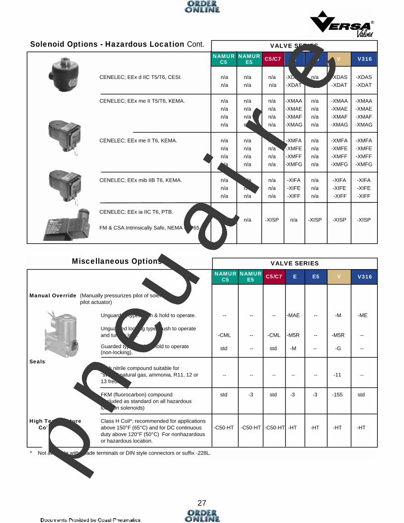
CENELEC; EEx d IIC T5/T6, CESI. n/a n/a n/a -XDAS n/a -XDAS -XDAS
n/a n/a n/a -XDAT n/a -XDAT -XDAT
CENELEC; EEx me II T5/T6, KEMA. n/a n/a n/a -XMAA n/a -XMAA -XMAA
n/a n/a n/a -XMAE n/a -XMAE -XMAE
n/a n/a n/a -XMAF n/a -XMAF -XMAF
n/a n/a n/a -XMAG n/a -XMAG -XMAG
CENELEC; EEx me II T6, KEMA. n/a n/a n/a -XMFA n/a -XMFA -XMFA
n/a n/a n/a -XMFE n/a -XMFE -XMFE
n/a n/a n/a -XMFF n/a -XMFF -XMFF
n/a n/a n/a -XMFG n/a -XMFG -XMFG
CENELEC; EEx mib IIB T6, KEMA. n/a n/a n/a -XIFA n/a -XIFA -XIFA
n/a n/a n/a -XIFE n/a -XIFE -XIFE
n/a n/a n/a -XIFF n/a -XIFF -XIFF
CENELEC; EEx ia IIC T6, PTB.
-XISP n/a -XISP n/a -XISP -XISP -XISP
FM & CSA.Intrinsically Safe, NEMA 4/IP65
Manual Override (Manually pressurizes pilot of solenoid/pilot actuator)
Unguarded type; push & hold to operate. -- -- -- -MAE -- -M -ME
Unguarded locking type; push to operateand turn to lock. -CML -- -CML -M5R -- -M5R --
Guarded type; push & hold to operate std -- std -M -- -G --(non-locking).
SealsHigh nitrile compound suitable for"sweet" natural gas, ammonia, R11, 12 or -- -- -- -- -- -11 --13 freon.
FKM (fluorocarbon) compound std -3 std -3 -3 -155 std(included as standard on all hazardouslocation solenoids)
High Temperature Class H Coil*; recommended for applicationsCoil above 150°F (65°C) and for DC continuous -C50-HT -C50-HT -C50-HT -HT -HT -HT -HT
duty above 120°F (50°C) For nonhazardousor hazardous location.
27
®
* Not available with spade terminals or DIN style connectors or suffix -228L.
Solenoid Options - Hazardous Location Cont.
Miscellaneous Options NAMUR
C5NAMUR
E5 C5/C7 E E5 V
NAMURC5
NAMURE5 C5/C7 E E5 V V316
VALVE SERIES
VALVE SERIES
V316
pneu
air
e


![ERIKS Econosto Valves Petrochemical Industry [EN]](https://img.dokumen.tips/doc/110x75/579090c31a28ab7b278dea87/eriks-econosto-valves-petrochemical-industry-en.jpg)