Embed Size (px)
Citation preview
Proceedings of the 2006 IEEE/RSJInternational Conference on Intelligent Robots and Systems
October 9 - 15, 2006, Beijing, China
A Novel Approach to Fault Detection and Identificationin Suction Foot Control of a Climbning Robot
Jiang Yong 2, Wang Hongguang 2, Fang Lijin', and Zhao Mingyang''Robotics Laboratory, Shenyang Institute ofAutomation, Chinese Academy of Sciences, Shenyang, 110016, China
2Graduate School ofthe Chinese Academy ofSciences, Beijing, 100039, ChinaE-mail: jiangyong(ksia.cn hgwang(ksia.cn ljfang(ksia.cn myzhaoqqsia.cn
Abstract -This paper presents a multiple-model and Booleanlogic reasoning (MMBLR) approach to detect and identify faultsin the suction foot control of a climbing robot. For this controlsystem, some fault models are easily given by kinematicsequations. Moreover, the logic relations of the system states havebeen known in advance. Based on the combination of themultiple-model adaptive estimation (MMAE) algorithm and theBoolean logic reasoning, the MMBLR approach is properly fitfor the fault detection and identification (FDI) application to theclimbing robot. In the MMBLR architecture, the MMAEalgorithm is used to reliably detect and identify the model-knownfaults. Then based on the robot's states and the results of theMMAE, other faults are detected and identified using theBoolean logic reasoning. Experimental results validated that thefaults of the sensors and actuators in the suction foot control ofthe robot can be readily detected and identified by the MMBLRapproach.
Index Terms - Fault detection and identification, Multiple-model adaptive estimation, Boolean logic reasoning, MMBLR,Climbing robot
I. INTRODUCTION
Since mobile robots are mostly designed to actautonomously, without direct supervision, the demand of faultdetection and identification (FDI) in such parts as sensors,actuators and control units are significantly increasing forassuring mobile robots reliability and safety. Over the years, anumber of different FDI techniques making use of eithermodel based approach (for example, Kalman filter basedapproach) or model-free based approach (for example, softcomputing based approach) have been proposed.
Model based FDI depends heavily on the presence of ananalytical model of the process. Based on the concept ofanalytical redundancy in this approach, a residual signal isgenerated by comparing the measured output signal and theestimated one from a nominal system model. After beingprocessed, this residual can be used as the indicator of thefault. Roumeliotis et al. [1] presented an execution of themultiple-model adaptive estimation (MMAE) to the FDI in thewheeled mobile robot Pioneer . Subsequently, Goel et al. [2]used the MMAE algorithm that integrated with a backpropagation neural network to diagnose the complex faults inPioneer AT, a four-wheeled robot. Further, in work byHashimoto et al. [3] an interacting multiple model (IMM)approach to sensor FDI in the dead reckoning of mobile robotwas proposed and thus greatly improved the performance forthe systems with frequent mode jumps. Washington [4]
presented MAKSI (Markov and Kalman state identification),an on-board method for fault diagnosis of the robot Rover.The MAKSI is based on a combination of continuousprobabilistic state estimation using Kalman filters and discretequalitative state estimation using a Markov modelrepresentation. In addition to Kalman filters, recently particlefilters have been developed and applied to the FDI problem ofmobile robots. Dearden et al. [5] successfully used particlefilters to detect and classify the faults in the Rover.
For nonlinear or uncertain systems, model based FDIapproaches do not perform well. To solve this problem,model-free based FDI approaches have been proposed. YoungMoon Park et al. [6] presented a LBES (logic based expertsystem) for fault diagnosis of power systems. Soika [7]proposed a concept for fault detection and calibration ofexternal sensors on mobile robots, based on a gridrepresentation of the environment. Other approaches, such asHMM2 (second-order hidden Markov models) based FDI [8]and FTA (fault tree analysis) based FDI [9] have also beenstudied.
In this paper, we present a MMBLR (multiple-model andBoolean logic reasoning) approach to detect and identify thefaults in the suction foot control of a climbing robot. Based ona combination of the MMAE algorithm and the Boolean logicreasoning, the MMBLR approach is properly fit for the FDI tothe sensors and actuators in the mobile robot. The organizationof the paper is as follows. Section II briefly describes themechanical structure and the suction foot of the climbingrobot. Section III proposes the MMBLR approach. Section TVanalyses the experimental results where the MMBLRapproach is used to detect and identify the faults in the suctionfoot control of the climbing robot. Finally, section V outlinesthe main conclusions of the work.
II. CLIMBING ROBOT
A. Mechanical StructureThe mechanical structure of the climbing robot is
designed as a bipedal robot with an under-actuated mechanism[10]. As shown in Fig. 1, motors 1 and 3 independently drivejoints 1 and 5, respectively, thereby adjusting the tilt angle ofthe suction feet land 2 so that the robot can grip the surfacefirmly. Motor 2 is installed to control joints 2, 3 and 4,separately. Joints 2 and 4 are revolute joints providing steeringcapability of the feet relative to the legs. Joint 3 represents theprismatic motion of the legs that allows the robot to expandand contract its legs.
1-4244-0259-X/06/$20.00 C)2006 IEEE3423
The under-actuated mechanism enables the robot to drivefive joints by only three motors, thus reducing both the weightand the power consumption of the robot, and achieving goodbalance between compactness and maneuverability.
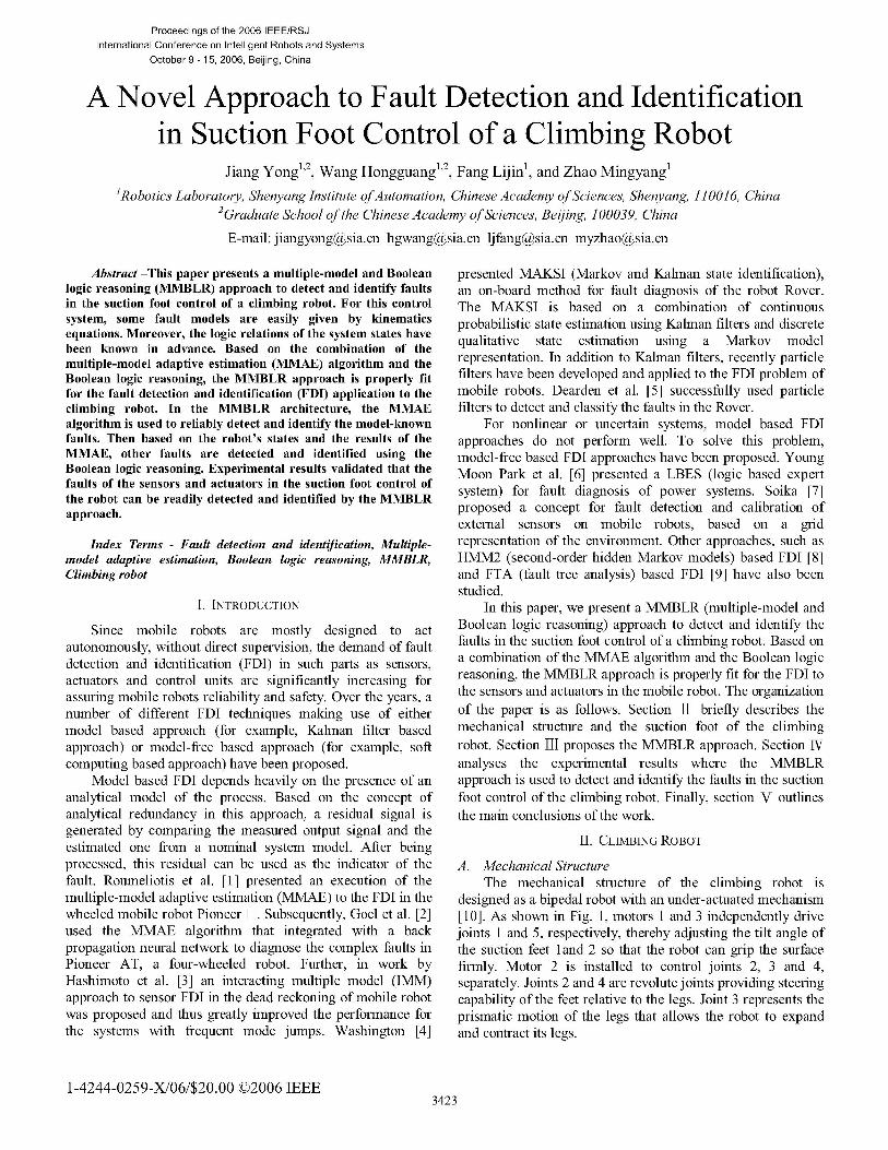
B. Suction FootThe bipedal climbing robot is supported by two suction
feet that provide the robot with the ability to walk on ahorizontal surface as well as climb a vertical wall. The suctionfoot is shown in Fig. 2.
valve Pressure sensor
Touch sensor
t) ~~Air loopN
Suction footVacuum pump
Fig. 2 Suction foot
Its main components are a diaphragm-type vacuum pump,a suction cup, a pressure sensor and a micro machined shapememory alloy valve. The connector integrates the footcomponents and serves as a mounting platform for the robotbody. The suction cup is used for adherence. The pressuresensor monitors the pressure level inside the suction cup toensure that the foot is firmly attached to the object surface.The foot is released through the actuation of the valve by asignal from the robot controller. Two touch sensors are alsoattached to the suction cup in opposite directions. This givesinformation on which part of the suction cup has touched thesurface and facilitates the robot in adjusting the suction footorientation.
III. FDI APPROACH
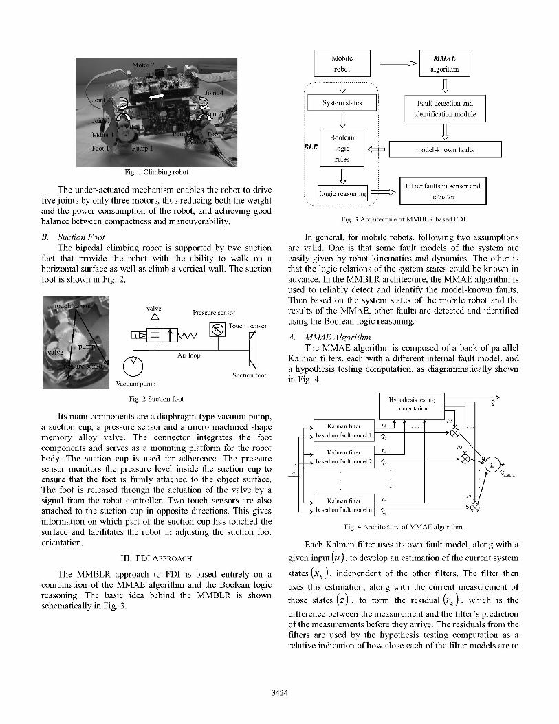
The MMBLR approach to FDI is based entirely on acombination of the MMAE algorithm and the Boolean logicreasoning. The basic idea behind the MMBLR is shownschematically in Fig. 3.
Mobile MMAErobot algorithm
.*| System states Fault detection and*Z43, .identification module
Boolean 0bBLR logic < model-known faults
rules
Other faults in sensor andLogic reasoning actuator
Fig. 3 Architecture ofMMBLR based FDI
In general, for mobile robots, following two assumptionsare valid. One is that some fault models of the system areeasily given by robot kinematics and dynamics. The other isthat the logic relations of the system states could be known inadvance. In the MMBLR architecture, the MMAE algorithm isused to reliably detect and identify the model-known faults.Then based on the system states of the mobile robot and theresults of the MMAE, other faults are detected and identifiedusing the Boolean logic reasoning.
A. MMAE AlgorithmThe MMAE algorithm is composed of a bank of parallel
Kalman filters, each with a different internal fault model, anda hypothesis testing computation, as diagrammatically shownin Fig. 4.
Kalman filter r1
_based on fault model I x2I u
Kalman filter r2based on fault model n
Fig. 4 Architecture ofMMAE algorithm
XM]ME
Each Kalman filter uses its own fault model, along with agiven input (u), to develop an estimation of the current system
states (k ), independent of the other filters. The filter thenuses this estimation, along with the current measurement ofthose states (z) , to form the residual (rk) , which is thedifference between the measurement and the filter's predictionof the measurements before they arrive. The residuals from thefilters are used by the hypothesis testing computation as arelative indication ofhow close each of the filter models are to
3424

the true model. The smaller the residual, the closer the filtermodel matches the true model. The hypothesis testingcomputation first scales the residuals to account for variousuncertainties and noises in the measurements, and thencomputes the conditional probability for each of thehypotheses modeled in the bank of Kalman filters (Pk) .These probabilities are then used to weight the individualKalman filter state estimates to produce a blended estimationof the true states (XMMAEA), which can then be used as theoptimal estimation of the states by a control system. Whenused for fault identification, each of the Kalman filters wouldmodel a different fault condition, and the residuals from eachfilter would indicate how close that filter's model is to theactual fault condition. By monitoring these residuals, thehypothesis test computation can estimate the current faultstatus of the system (a) .
The model for the kth filter is assumed to be a lineartime-invariant, discrete-time system of the form
Xk (ti+1) = ( kXk (ti ) + BkU(ti)+ GkWk (ti) (1
z(ti) = HkXk (ti ) + Vk (ti )
where xk is the Kalman filter model state vector; (D k is the
Kalman filter model state transition matrix; B k is the Kalmanfilter model control input matrix; u is the system input vector;Gk is the Kalman filter model noise input matrix; wk is awhite discrete-time dynamics noise input; z is the Kalmanfilter model measurement vector; Hk is the Kalman filter
model output matrix; vk is a white measurement noise input.
The statistics characteristics of wk and vk are
E[Wk (ti )] = 0 E[Vk (ti )]' o (2)
E[Wk(ti )WT (ty )] = ' O (3)
ti = t
ti # tiE[wk (ti )VT (ti )] 0
(4)
(5)
The state estimate Xk ('>) and its covariance matrix
P +(> )are propagated forward from time t11 to time t bythe discrete time propagation equations
Xk(ti ) =Pkkk(Q)+Bku@- ) (6)
Pk (i ) D)kPk (t-I )4k kkQk (ti-I )Gk (7
The propagated optimal state estimate and its covariancematrix are then updated with information from the current
measurement z(ti) weighted according to a Kalman filter
gainKk (ti ) . The update equations are
Kk(ti)=Pkti )Hk [HkPk(ti )H +Rk (ti )]
Xk (ti ) Xk(ti )+ Kk (ti )[Zk (ti )-IkXk(t )]
Pk (i ) k(i ) k (ti )HkPk (i)
(8)(9)
(10)
Given that fault k has occurred (1 < k < n) and themeasurement history vector is
zi- [z (tl )... ZT
(til )]T (1 1)
The conditional density function of the measurement z(ti ) iscomputed as
f((t )ak IZi-i (z(ti )|ak I Zi-l ) = 22 Isk 1 l2 ) 'e1 le2rk (ti)Sk ti (12)
where ak is a vector of parameters specific to the kth fault;
m is the dimension of the measurement vector z(ti ); Sk iSthe covariance of the residual. The conditional probability
Pk can be computed as
fz(t )ak,Zi-l (Zti )ak,zz- )Pk (t- )
/=1 z(t ) a,zil ((ti ) aj , zi-l )P (ti-l )(13)
B. Boolean Logic ReasoningThe Boolean logic reasoning (BLR) based FDI in mobile
robots is used to detect and identify the faults of the sensors,actuators and control units according to the logic relations ofthe system states. Here, the BLR approach relies on the keyassumption that the characteristics of the system can bedistinguished using Boolean algebra, i.e., "O" and "1". TheBLR approach consists of a system state module, a Booleanlogic rule module and a logic reasoning module, as shown inFig. 3.
For using the Boolean logic reasoning to detect andidentify the faults in mobile robots, first of all, we must definea cause Boolean function A(A1 , A2, .,, Am )where A1,A2, *...,Am are m fault causes, an omen Boolean
function C(Cl1C2,..* Cn ) where c1,c2, *.* *, cn are n faultomens, and a decision Booleanfunction E(A1l A2, , Am; cl I C2 .. Cn ) . The decision
function E( )is formulated based on the logic relations of thesystem states. Then the basic problem of the BLR based FDIis how to detect and identify the fault causes (causefunction A(.)), if the fault omens (omen function C()) and
3425
1-
(ti )VT RkE k i 0
the decision rules (decision function E()) have been knownin advance.
The process of the BLR based FDI is described asfollows.
Step 1: Analyze the possible fault omens cl,C2, 'eCn
and causes A1,A2, *.., Am in the system.
Step 2: Define the logic rules Ri , i = 1,2, for example
R1: A1 cl, i.e., IF the fault cause is A1, THEN theomen is Cl .
R2: c1c2-+ A2, i.e., IF the fault omen is the logicAND ofc1 and C2, THEN the cause is A2.
R3:A1 +A3 iC1c3, i.e., IF the fault cause is the
logic OR of A1 and A3, THEN the omen is the logic AND
of c1 and c3 .
Step 3: Based on the truth table of the fault causes, omensand logic rules, deduce the decision function E().
Step 4: Identify the fault causes using decisionfunction E (-)and real omens occurred in the system.
TV. EXPERIMENTS
A. Suction Foot ControlThe bipedal climbing robot has the ability to transit
between differently inclined surfaces. When moving from afloor to an object surface, the most important thing the robotneeds to do is to adjust the suction foot orientation in orderthat the suction cup can fully contact the object surface. Theprocess of the suction foot control is as follows.
Step 1: Rotate Joint 1 to bring the suction cup (foot 2)near the object surface.
Step 2: When either of the two touch sensors attached tothe suction cup generates a signal (The signal means that thispart of the suction cup has touched the object surface), Joint 5is rotated to make the untouched part near the object surface.
Step 3: If neither of the two touch sensors has generated asignal, carry out Step 1.
Step 4: When both of the two touch sensors generatesignals synchronously, start the vacuum pump and then thepressure sensor monitors the pressure level inside the suctioncup to ensure that the foot 2 is firmly attached to the objectsurface.
B. Experimental ResultsIn the experiments reported here, the MMBLR approach
is used to detect and identify the faults in the suction footcontrol of the climbing robot, as shown in Table El.
TABLE IFAULTS AND FDI APPROACH
Main components FDI approachof the suction foot control
Touch sensor 1 MMAE
Touch sensor 2Vacuum pump BLRPressure sensor
A D-H coordinate system has been established for eachrobot link, as shown in Fig. 5.
Fig. 5 D-H Coordinate System
A kinematics of the climbing robot is then given by
X(t + 1) = OX(t) + BU(t) + GI W(t)Z(t) = HX(t) + G2V(t)1 0 0 0 -b -c -a
0 1 0 0 -C b 0(D = H =B=
0 0 1 0 -b c -a
_0 0 0 1 _ c b 0
g1 0 0 0 g2 0 0_ 0 g1 0 0 0 g2 0
0 ° g1 0 0 0 g20 0 0 g1_ 0 0 0
(14)
0a
0a
000
g2 _
where t + 1 and t are sampling times. The state
vector X = [X1 X2 X3 X4 represents the points Aand B (where the touch sensors 1 and 2 are attached to thesuction cup, separately) positions with respect to the referenceframe. Each input ui ( i = 1,.- ,4 ) of the input
vector U = [U1 U2 U3 U4 ]T is the function of the joint
variables 01 and 02 The noise vectors
w = kW w2, w wI and
V = [V1 V2 V3 V4 are assumed to be zero-mean whiteGaussian sequences. The statistics characteristics ofW and V are described as (2)-(5). Theparametersa = 180,b = 40, c = 22, g, = 2,g2 = 0.1 -
The experimental results of the MMAE based FDI to thetouch sensors are shown in Fig. 6.
3426
200 __ a L__ _ 2 200
1_ 450
100 I 1-0
.50
5050~~~~~~~~~~~~~~~~~0 2 4 6 8 10 a 50 1 15D 20
ErnO1i ser^'divw XSxes (,llM'i
_I
8/I
05 - - - - - - - - -r --- - -,--I-- - - - --
0 ~~ Ll 0 J Jo :2 4 6 8 10 S8 loG 102 104 106
Tmime (,Iseslditj RP atioril angle &joirt
(a) Touch sensors 1 and 2 faults
2o0 - 00
50 2 x 3 419 10
100 I- - 0-2 -- 7- F-
50 -fl (1 --6 81------- IOO 120 160
l~~~~b Toc sensor1 faul
50
O 2 4 6 8 1a 4 60 100 160 2o0Timre (lsec1dio >aes oni)
0.8 T_ r - r-- 'r - t- r r -
I I~~~~~~~~~~~~~~~~~~~~~~~~~
O. - r 0.4 - -
02 4- 0Q k
° 24 - -- 10--- - &-- --l- -- - s- - - - &l -8--- - -1--- - --- -
O 2 4 6 10 1100 12D0 140t 1Z 10Timle (lsecfdiA Rtatibnal ange of ,0iti 5
(b) Touch sensor I fault-
1
a 1!90 #4 1bX3 <//~~~~~~~~0 10
100 - -- - - -o/
il 2 4 6 8 10 0 SilA 10DI 1b 2100lirne (lsecidh :>axes (mmn)
M111_ ___ _|F _ _| __ _ (1!8 - -- - --r- ____ ___
0° - - - - D.- - - - :- - - - - -1> :_
01.4 -- - ---- 4--1 - - - DA - ---: - - - -}r - __ -s-_-g -_ _-_
D 01D 4 65 8 1Q 60 810 1104 120{ li
Tne (1secfid Rotational angle of jint 5
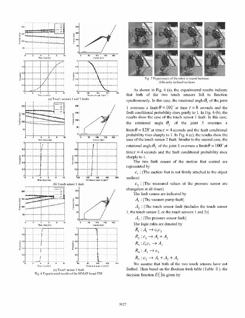
(c) Touch sensor 2 faultFig. 6 Experimental results of the MMAE based FDI
Fig. 7 Experiments ofthe robot to transit betweendifferently inclined surfaces
As shown in Fig. 6 (a), the experimental results indicatethat both of the two touch sensors fail to functionsynchronously. In this case, the rotational angle 01 of the joint
1 overruns a limit 0 = 101 at time t = 8 seconds and thefault conditional probability rises gently to 1. In Fig. 6 (b), theresults show the case of the touch sensor 1 fault. In this case,the rotational angle 02 of the joint 5 overruns a
limit 0 = 128 at timet = 4 seconds and the fault conditionalprobability rises sharply to 1. In Fig. 6 (c), the results show thecase of the touch sensor 2 fault. Similar to the second case, therotational angle 02 of the joint 5 overruns a limit 0 = 100 at
time t = 4 seconds and the fault conditional probability risessharply to 1.
The two fault omens of the suction foot control arerepresented by
c1: {The suction foot is not firmly attached to the objectsurface}
c {The measured values of the pressure sensor arechangeless at all times}
The fault causes are indicated byA1: {The vacuum pump fault}
A2: {The touch sensor fault (includes the touch sensor1, the touch sensor 2, or the touch sensors 1 and 2)}
A3 : {The pressure sensor fault}The logic rules are denoted byR1:A1 c1C2R2 :c1 -A1 +A2R3 : c2 -*A3R4 :A3- C2R5:C2 ->A1 +A2 +A3We assume that both of the two touch sensors have not
faulted. Then based on the Boolean truth table (Table II), thedecision function E(.)is given by
3427
2
i!

E= AiA2A3CIC2 +AiA2A3cic2 +A1A2A3C1c2+ A1A2A3c1c2
If the fault omens c1 and c2 have occurred, we could deduce
that the fault cause is Al1, i.e., the vacuum pump fault.
Al A3+A1A3 =Al (16)
V. CONCLUSIONS
This paper presented the MMBLR (multiple-model andBoolean logic reasoning) approach to sensor and actuator faultdetection and identification in the suction foot control of thebipedal climbing robot. For this control system, the faultmodels of the two touch sensors are easily given by the robotkinematics. Moreover, we have known the certain logicrelations of the system states in advance. Then based on thecombination of the MMAE algorithm and the Boolean logicreasoning, the MMBLR approach is properly fit for the FDI inthe suction foot control. The experimental results validatedthat the faults of the sensors and actuators in the robot can beeasily detected and identified by the MMBLR approach.
REFERENCES
[1] 5. I. Roumeliotis, G. S. Sukhatme, and G. A. Bekey, "Sensor faultdetection and identification in a mobile robot," IEEEIRSJ International
Conference on Intelligent Robots and Systems. vol. 3. pp. 1383-1388. Oct.1998.
[2] P. Goel, G. Dedeoglu, S. I. Roumeliotis, and G. S. Sukhatme, "Faultdetection and identification in a mobile robot using multiple modelestimation and neural network," IEEE International Conference onRobotics andAutomation, vol. 3, pp. 2302-2309, April 2000.
[3] M. Hashimoto, H. Kawashima, T. Nakagami, and F. Oba, "Sensor faultdetection and identification in dead-reckoning system of mobile robot:interacting multiple model approach," IEEEIRSJ InternationalConference on Intelligent Robots and Systems, vol. 3, pp. 1321-1326,Oct.- Nov. 2001.
[4] R. Washington, "On-board real-time state and fault identification forrovers," IEEE International Conference on Robotics andAutomation, vol.2, PP. 1175-1181, April 2000.
[5] R. Dearden, T. Willeke, R. Simmons, V. Verma, F. Hutter, and S. Thniun,"Real-time fault detection and situational awareness for rovers: report onthe Mars technology program task," IEEE Aerospace Conference, vol. 2,pp. 826-840, March 2004.
[6] Young Moon Park, Gwang-Won Kim, and Jin-Man Sohn, "A logic basedexpert system for fault diagnosis of power system," IEEE Transactions onPower System, vol. 12, no. 1, pp. 363-369. Feb. 2001.
[7] M. Soika, "Grid based fault detection and calibration of sensors on mobilerobots," IEEE International Conference on Robotics andAutomation, vol.3, pp. 2589-2594, April 1997.
[8] 0. Aycard, and R. Washington, "State identification for planetary rovers:learning and recognition," IEEE International Conference on RoboticsandAutomation, vol. 2, pp. 1163-1168, April 2000.
[9] M. G. M. Madden, and P. J. Nolan, "Monitoring and diagnosis of multipleincipient faults using fault tree induction," IEE proc.-Control TheoryApplication, vol. 146, No.2, March 1999.
[10]J. Z. Xiao, Hans Dulimarta, N. Xi, and R. L. Tummala, "Modeling andcontrol of an under-actuated miniature crawler robot," IEEEIRSJInternational Conference on Intelligent Robots and Systems, pp. 1546-155 1, Hawaii, USA, 2001.
TABLE II____________________ ~~BOOLEAN TRUTH TABLE
CC2 C C4 ~C ( C C8 C9 co0 C C' C' C' C' C'6
Al 0 0 0 0 0 0 0 0 1 1 1 1 1 1 1 1
A20 0 0 0 0 0 0 0 0 0 0 0 0 0 0 0Causesand A30 0 0 0 1 1 1 1 0 0 0 0 1 1 1 1
omenscl0 0 1 1 0 0 1 1 0 0 1 1 0 0 1 1
c2 0 1 0 1 0 1 0 1 0 1 0 1 0 1 0 1
A19c1c2 1 1 1 1 1 1 1 1 0 0 0 1 0 0 0 1
cI*AI+A2 1 1 0 0 1 1 0 0 1 1 1 1 1 1 1 1Logicrules 1i2->A 0 1 1 1 1 1 1 1 0 1 1 1 1 1 1
A3 c2 1 1 1 1 0 1 0 1 1 1 1 1 0 1 0 1
c2 A]+A2+A3 1 0 1 0 1 1 1 1 1 1 1 1 1 1 1 1
E(.) 1 0 0 0 0 1 0 0 0 0 0 1 0 0 0 1
3428


![g]kfndf afnljjfx cGTosf] nflu / fli6«o ;~hfn · g]kfndf afnljjfx cGTosf] nflu / fli6«o ;~hfn The National Network to End Child Marriage in Nepal : An Introduction ! Rashmila(Shakya,(Member(Na2onal(Networkto(End(Child](https://img.dokumen.tips/doc/110x75/5f60246f18a15f7cd8703dd3/gkfndf-afnljjfx-cgtosf-nflu-fli6o-hfn-gkfndf-afnljjfx-cgtosf-nflu-fli6o.jpg)