Embed Size (px)
Citation preview
Applied Acoustics 68 (2007) 797–819
www.elsevier.com/locate/apacoust
Procedures for determining the acoustic efficiencyof edge-modified noise barriers
Tomonao Okubo *, Kohei Yamamoto
Kobayasi Institute of Physical Research, 3-20-41 Higashi-motomachi, Kokubunji, 185-0022 Tokyo, Japan
Received 16 February 2006; received in revised form 28 March 2006; accepted 11 April 2006Available online 5 June 2006
Abstract
This paper describes the noise shielding efficiency of barriers with an acoustic device mounted ontheir top edge for reducing sound diffraction. Diffraction behind the edge-modified barrier is inves-tigated by scale model experiments in which the positions of a source and a receiver are aligned alonga circular arc around the barrier top. The result indicates that the acoustic efficiency of the edgedevice is a function of the angles of the source and receiver and independent of their radii. Basedon this finding, a novel procedure for determining the efficiency of manufactured edge devices isestablished. This procedure is very beneficial for estimating the edge device efficiency by eliminatingground and meteorological effects. The measured efficiency of the device will be quite useful for theprediction of noise propagation behind the edge-modified barriers.� 2006 Elsevier Ltd. All rights reserved.
Keywords: Noise barriers; Efficiency determination; Diffraction; Noise propagation prediction; Road traffic noise
1. Introduction
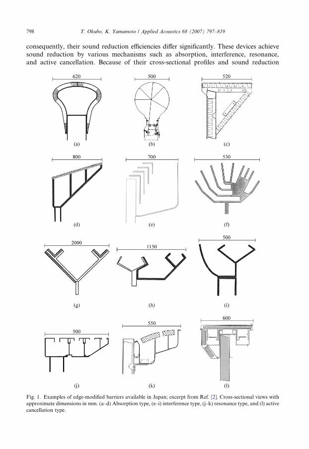
After the invention of an absorbing cylindrical edge by Fujiwara and Furuta [1], edge-modified barriers have been vigorously developed to reduce noise around road trafficareas. In Japan, approximately 20 types of devices that modify the edge shape of the noisebarrier, including 12 examples shown in Fig. 1 [2], are distributed as commercial products.Their thickness (i.e. cross-sectional width) is in the broad range of 500–2000 mm;
0003-682X/$ - see front matter � 2006 Elsevier Ltd. All rights reserved.
doi:10.1016/j.apacoust.2006.04.002
* Corresponding author. Tel.: +81 42 321 2841; fax: +81 42 322 4698.E-mail address: [email protected] (T. Okubo).
798 T. Okubo, K. Yamamoto / Applied Acoustics 68 (2007) 797–819
consequently, their sound reduction efficiencies differ significantly. These devices achievesound reduction by various mechanisms such as absorption, interference, resonance,and active cancellation. Because of their cross-sectional profiles and sound reduction
Fig. 1. Examples of edge-modified barriers available in Japan; excerpt from Ref. [2]. Cross-sectional views withapproximate dimensions in mm. (a–d) Absorption type, (e–i) interference type, (j–k) resonance type, and (l) activecancellation type.
T. Okubo, K. Yamamoto / Applied Acoustics 68 (2007) 797–819 799
mechanisms, the frequency characteristics of the sound reduction efficiencies become com-plicated. Numerical analyses [3] have revealed that the edge device efficiency depends onthe profile and mechanism and the efficiency difference among devices increases up to8 dB, when a barrier with a height of 3 m on a flat terrain is considered against an A-weighted vehicle noise spectrum. The difference will increase at larger diffraction angles,such as those in the case of depressed, embankment, or elevated roads.
Road traffic administrators should recognize the efficiency difference among edgedevices accurately in order to decide the device to be used and predict noise propagationbehind the edge-modified barrier. Generally, to determine the efficiency of the entire noisebarrier, including the effects of both the straight barrier portion and the edge device, ISO10847 [4] or any equivalent procedure is adopted. Estimation of the efficiency differenceamong edge devices by comparison of the ISO measurement results appears to be an easytask. In practice, however, it is a very difficult task because the measured efficiency of theentire barrier is strongly affected by the ground effect (interference due to reflection andexcess attenuation due to absorption) and meteorological conditions. Therefore, measure-ments based on this ISO standard cannot be used to estimate and compare the intrinsicefficiency of the device.
Recently, measurement procedures for determining the intrinsic efficiency of edge deviceshave been developed. A series of procedures for determining the efficiency of a noise-reduc-ing device mounted on top of a barrier has been proposed by CEN/TS 1793-4 [5]. The CEN/TS is an innovative method for excluding reflections from the ground surface and extractingonly direct diffraction (i.e. diffracted sound that propagates directly from the edge withoutbeing reflected from any other object), introducing impulse response measurement aroundthe edge. It is very useful to estimate the intrinsic efficiency of edge devices independent of thelocal terrain of the test facility. On the other hand, the CEN/TS or related articles have notyet provided any reasonable basis for the alignment of the loudspeaker and microphone intheir measurement procedures. Although single-number ratings of the device efficiencyweighted with the road vehicle noise spectrum have been provided, the rating is too simpli-fied to predict noise propagation when terrain effects are considered.
The authors have proposed similar determination procedures for excluding the reflec-tion from the ground and have investigated the efficiency of edge devices mounted ontop of semi-infinite barriers by numerical analyses [6]. By describing the positions of asource and a receiver in the cylindrical coordinate system, it has been proved that the effi-ciency of the edge device is determined by the frequency and angles of the source and recei-ver and it is independent of their radii. Based on the finding that the efficiency is a functionof the frequency and angles, a novel concept for the prediction of noise propagation by theintroduction of the measured efficiency has been proposed. This study experimentally val-idates the hypothesis that the efficiency of the edge device can be expressed as a function ofthe frequency and angles of the source and receiver in order to demonstrate the feasibilityof the proposed concept of efficiency determination and propagation prediction.
2. Basic concept
2.1. Barrier diffraction expressed as directivity centred on the edge
It is generally known that the noise shielding efficiency of a barrier increases when itsedge profile is reasonably modified. We discuss this principle by using the analytical
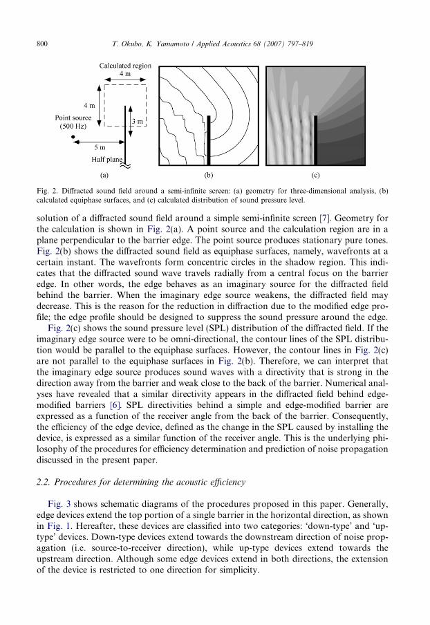
Fig. 2. Diffracted sound field around a semi-infinite screen: (a) geometry for three-dimensional analysis, (b)calculated equiphase surfaces, and (c) calculated distribution of sound pressure level.
800 T. Okubo, K. Yamamoto / Applied Acoustics 68 (2007) 797–819
solution of a diffracted sound field around a simple semi-infinite screen [7]. Geometry forthe calculation is shown in Fig. 2(a). A point source and the calculation region are in aplane perpendicular to the barrier edge. The point source produces stationary pure tones.Fig. 2(b) shows the diffracted sound field as equiphase surfaces, namely, wavefronts at acertain instant. The wavefronts form concentric circles in the shadow region. This indi-cates that the diffracted sound wave travels radially from a central focus on the barrieredge. In other words, the edge behaves as an imaginary source for the diffracted fieldbehind the barrier. When the imaginary edge source weakens, the diffracted field maydecrease. This is the reason for the reduction in diffraction due to the modified edge pro-file; the edge profile should be designed to suppress the sound pressure around the edge.
Fig. 2(c) shows the sound pressure level (SPL) distribution of the diffracted field. If theimaginary edge source were to be omni-directional, the contour lines of the SPL distribu-tion would be parallel to the equiphase surfaces. However, the contour lines in Fig. 2(c)are not parallel to the equiphase surfaces in Fig. 2(b). Therefore, we can interpret thatthe imaginary edge source produces sound waves with a directivity that is strong in thedirection away from the barrier and weak close to the back of the barrier. Numerical anal-yses have revealed that a similar directivity appears in the diffracted field behind edge-modified barriers [6]. SPL directivities behind a simple and edge-modified barrier areexpressed as a function of the receiver angle from the back of the barrier. Consequently,the efficiency of the edge device, defined as the change in the SPL caused by installing thedevice, is expressed as a similar function of the receiver angle. This is the underlying phi-losophy of the procedures for efficiency determination and prediction of noise propagationdiscussed in the present paper.
2.2. Procedures for determining the acoustic efficiency
Fig. 3 shows schematic diagrams of the procedures proposed in this paper. Generally,edge devices extend the top portion of a single barrier in the horizontal direction, as shownin Fig. 1. Hereafter, these devices are classified into two categories: ‘down-type’ and ‘up-type’ devices. Down-type devices extend towards the downstream direction of noise prop-agation (i.e. source-to-receiver direction), while up-type devices extend towards theupstream direction. Although some edge devices extend in both directions, the extensionof the device is restricted to one direction for simplicity.
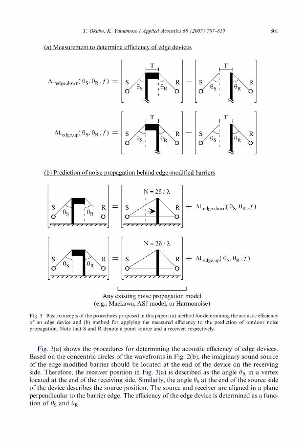
Fig. 3. Basic concepts of the procedures proposed in this paper: (a) method for determining the acoustic efficiencyof an edge device and (b) method for applying the measured efficiency to the prediction of outdoor noisepropagation. Note that S and R denote a point source and a receiver, respectively.
T. Okubo, K. Yamamoto / Applied Acoustics 68 (2007) 797–819 801
Fig. 3(a) shows the procedures for determining the acoustic efficiency of edge devices.Based on the concentric circles of the wavefronts in Fig. 2(b), the imaginary sound sourceof the edge-modified barrier should be located at the end of the device on the receivingside. Therefore, the receiver position in Fig. 3(a) is described as the angle hR in a vertexlocated at the end of the receiving side. Similarly, the angle hS at the end of the source sideof the device describes the source position. The source and receiver are aligned in a planeperpendicular to the barrier edge. The efficiency of the edge device is determined as a func-tion of hS and hR.

802 T. Okubo, K. Yamamoto / Applied Acoustics 68 (2007) 797–819
The definition of the efficiency is distinguished based on the extension direction ofthe device described previously: DLedge,down(hS,hR, f) for down-type devices andDLedge,up(hS,hR, f) for up-type devices. To some extent, the efficiency must depend on fre-quency; therefore, the frequency f is added to the parameters. From Fig. 3(a), we define thefollowing equations:
DLedge;downðhS; hR; f Þ ¼ Ledge;downðhS; hR; f Þ � LsimpleðhS; hR; f Þ ð1ÞDLedge;upðhS; hR; f Þ ¼ Ledge;upðhS; hR; f Þ � LsimpleðhS; hR; f Þ ð2Þ
where Lsimple(hS,hR, f), Ledge,down(hS,hR, f), and Ledge,up(hS,hR, f) denote the SPLs measuredbehind a simple barrier, edge-modified barrier with a down-type device, and edge-modifiedbarrier with an up-type device, respectively. The definition indicates that the values ofDLedge,down(hS,hR, f) and DLedge,up(hS,hR, f) are negative when the tested edge device is effi-cient for reducing sound diffraction.
It should be noted that the barriers for the efficiency measurement should be semi-infinite half planes; hence, reflections from the floor of the test room must be eliminated.In measurements on a simple barrier, the origin of hS is separated from the barrier edgeby the device thickness T in order to consider the effect of thickness as a part of theintrinsic device efficiency. Sections 3 and 4 describe the measurement procedures indetail.
2.3. Application to the prediction model of outdoor noise propagation
Fig. 3(b) shows the procedures for applying the measured efficiency of theedge device to the prediction of noise propagation. First, we predict noise propagationby assuming a simple barrier. Next, we add the measured edge efficiencyDLedge,down(hS,hR, f) or DLedge,up(hS,hR, f) to the prediction. From Fig. 3(b), we definethe following equations:
L̂edge;downðhS; hR; f Þ ¼ L̂simpleðhS; hR; f Þ þ DLedge;downðhS; hR; f Þ ð3ÞL̂edge;upðhS; hR; f Þ ¼ L̂simpleðhS; hR; f Þ þ DLedge;upðhS; hR; f Þ ð4Þ
where L̂simpleðhS; hR; f Þ, L̂edge;downðhS; hR; f Þ, and L̂edge;upðhS; hR; f Þ denote the predicted SPLsbehind a simple barrier, edge-modified barrier with a down-type device, and edge-modifiedbarrier with an up-type device, respectively. With regard to the down-type device, it shouldbe noted that the position of the simple barrier does not correspond to the position of thestraight wall portion of the edge-modified barrier in both efficiency estimation and noiseprediction.
The fundamental estimation L̂simpleðhS; hR; f Þ can be calculated by using any existingprediction model, e.g. Maekawa’s empirical chart [8], multiple-path method by Lamand Roberts [9], models by the Acoustical Society of Japan [10], and Harmonoiseengineering method [11]. Some of these models can appropriately predict the groundeffect caused by absorption and the terrain profile. The measured efficiencyDLedge,down(hS,hR, f) or DLedge,up(hS,hR, f) can be superposed on the results of simplebarrier prediction because the efficiency is independent of the ground effect. In anotherpaper, it will be reported that the measured efficiency can be applied to predict the dif-fraction behind edge-modified barriers precisely even when the reflective ground causesinterference [12].

T. Okubo, K. Yamamoto / Applied Acoustics 68 (2007) 797–819 803
3. Verification of the proposed procedure by scale model experiments
In this section, the diffracted sound field behind edge-modified barriers is investigatedby 1/10 scale model experiments in order to validate the procedures for determinationand prediction proposed in the previous section.
3.1. Tested edge devices
Fig. 4 shows the cross-sectional profiles of the edge devices whose efficiencies areinvestigated in this study. In this figure, noise sources and receivers are assumed tobe located on the left- and right-hand sides, respectively. Note that the dimensionsare shown in real scale, and that they are scaled down into 1/10 scale for miniaturemodels of the devices which are applied to experiments in the following section. Fourprofiles are examined: overhanging plates with an absorbing top or channels parallel tothe barrier edge [13] extended in the upstream and downstream directions. Hereafter,these four devices are referred to as Absorber-Down, Absorber-Up, Channels-Down,and Channels-Up. It is expected that the two Absorbers will generally improve thebarrier efficiency in the high-frequency range. The two Channels work efficientlyaround 500 Hz where the interference in each channel is designed to reduce diffraction[13].
Fig. 4. Cross-sectional profiles of edge devices investigated in this study (unit: mm). The noise source is on theleft-hand side.
804 T. Okubo, K. Yamamoto / Applied Acoustics 68 (2007) 797–819
3.2. Overview of scale model experiments
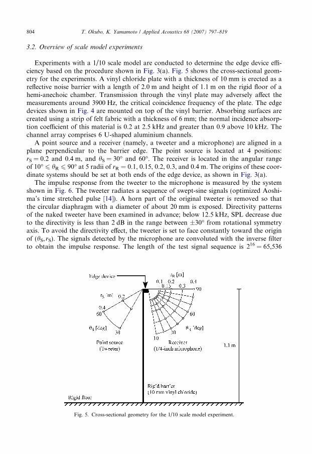
Experiments with a 1/10 scale model are conducted to determine the edge device effi-ciency based on the procedure shown in Fig. 3(a). Fig. 5 shows the cross-sectional geom-etry for the experiments. A vinyl chloride plate with a thickness of 10 mm is erected as areflective noise barrier with a length of 2.0 m and height of 1.1 m on the rigid floor of ahemi-anechoic chamber. Transmission through the vinyl plate may adversely affect themeasurements around 3900 Hz, the critical coincidence frequency of the plate. The edgedevices shown in Fig. 4 are mounted on top of the vinyl barrier. Absorbing surfaces arecreated using a strip of felt fabric with a thickness of 6 mm; the normal incidence absorp-tion coefficient of this material is 0.2 at 2.5 kHz and greater than 0.9 above 10 kHz. Thechannel array comprises 6 U-shaped aluminium channels.
A point source and a receiver (namely, a tweeter and a microphone) are aligned in aplane perpendicular to the barrier edge. The point source is located at 4 positions:rS = 0.2 and 0.4 m, and hS = 30� and 60�. The receiver is located in the angular rangeof 10� 6 hR 6 90� at 5 radii of rR = 0.1, 0.15, 0.2, 0.3, and 0.4 m. The origins of these coor-dinate systems should be set at both ends of the edge device, as shown in Fig. 3(a).
The impulse response from the tweeter to the microphone is measured by the systemshown in Fig. 6. The tweeter radiates a sequence of swept-sine signals (optimized Aoshi-ma’s time stretched pulse [14]). A horn part of the original tweeter is removed so thatthe circular diaphragm with a diameter of about 20 mm is exposed. Directivity patternsof the naked tweeter have been examined in advance; below 12.5 kHz, SPL decrease dueto the directivity is less than 2 dB in the range between ±30� from rotational symmetryaxis. To avoid the directivity effect, the tweeter is set to face constantly toward the originof (hS, rS). The signals detected by the microphone are convoluted with the inverse filterto obtain the impulse response. The length of the test signal sequence is 216 = 65,536
Fig. 5. Cross-sectional geometry for the 1/10 scale model experiment.
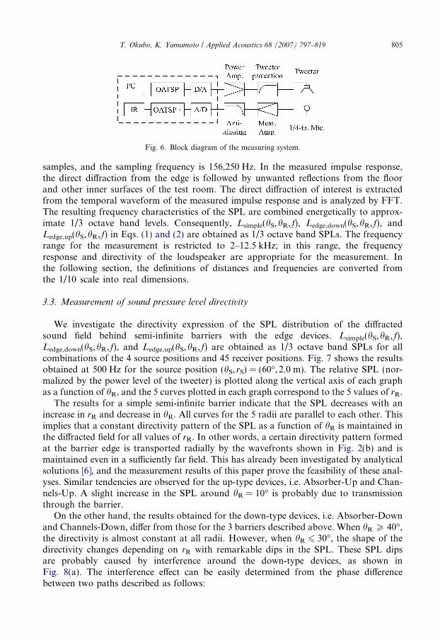
Fig. 6. Block diagram of the measuring system.
T. Okubo, K. Yamamoto / Applied Acoustics 68 (2007) 797–819 805
samples, and the sampling frequency is 156,250 Hz. In the measured impulse response,the direct diffraction from the edge is followed by unwanted reflections from the floorand other inner surfaces of the test room. The direct diffraction of interest is extractedfrom the temporal waveform of the measured impulse response and is analyzed by FFT.The resulting frequency characteristics of the SPL are combined energetically to approx-imate 1/3 octave band levels. Consequently, Lsimple(hS,hR, f), Ledge,down(hS,hR, f), andLedge,up(hS,hR, f) in Eqs. (1) and (2) are obtained as 1/3 octave band SPLs. The frequencyrange for the measurement is restricted to 2–12.5 kHz; in this range, the frequencyresponse and directivity of the loudspeaker are appropriate for the measurement. Inthe following section, the definitions of distances and frequencies are converted fromthe 1/10 scale into real dimensions.
3.3. Measurement of sound pressure level directivity
We investigate the directivity expression of the SPL distribution of the diffractedsound field behind semi-infinite barriers with the edge devices. Lsimple(hS,hR, f),Ledge,down(hS,hR, f), and Ledge,up(hS,hR, f) are obtained as 1/3 octave band SPLs for allcombinations of the 4 source positions and 45 receiver positions. Fig. 7 shows the resultsobtained at 500 Hz for the source position (hS, rS) = (60�, 2.0 m). The relative SPL (nor-malized by the power level of the tweeter) is plotted along the vertical axis of each graphas a function of hR, and the 5 curves plotted in each graph correspond to the 5 values of rR.
The results for a simple semi-infinite barrier indicate that the SPL decreases with anincrease in rR and decrease in hR. All curves for the 5 radii are parallel to each other. Thisimplies that a constant directivity pattern of the SPL as a function of hR is maintained inthe diffracted field for all values of rR. In other words, a certain directivity pattern formedat the barrier edge is transported radially by the wavefronts shown in Fig. 2(b) and ismaintained even in a sufficiently far field. This has already been investigated by analyticalsolutions [6], and the measurement results of this paper prove the feasibility of these anal-yses. Similar tendencies are observed for the up-type devices, i.e. Absorber-Up and Chan-nels-Up. A slight increase in the SPL around hR = 10� is probably due to transmissionthrough the barrier.
On the other hand, the results obtained for the down-type devices, i.e. Absorber-Downand Channels-Down, differ from those for the 3 barriers described above. When hR P 40�,the directivity is almost constant at all radii. However, when hR 6 30�, the shape of thedirectivity changes depending on rR with remarkable dips in the SPL. These SPL dipsare probably caused by interference around the down-type devices, as shown inFig. 8(a). The interference effect can be easily determined from the phase differencebetween two paths described as follows:
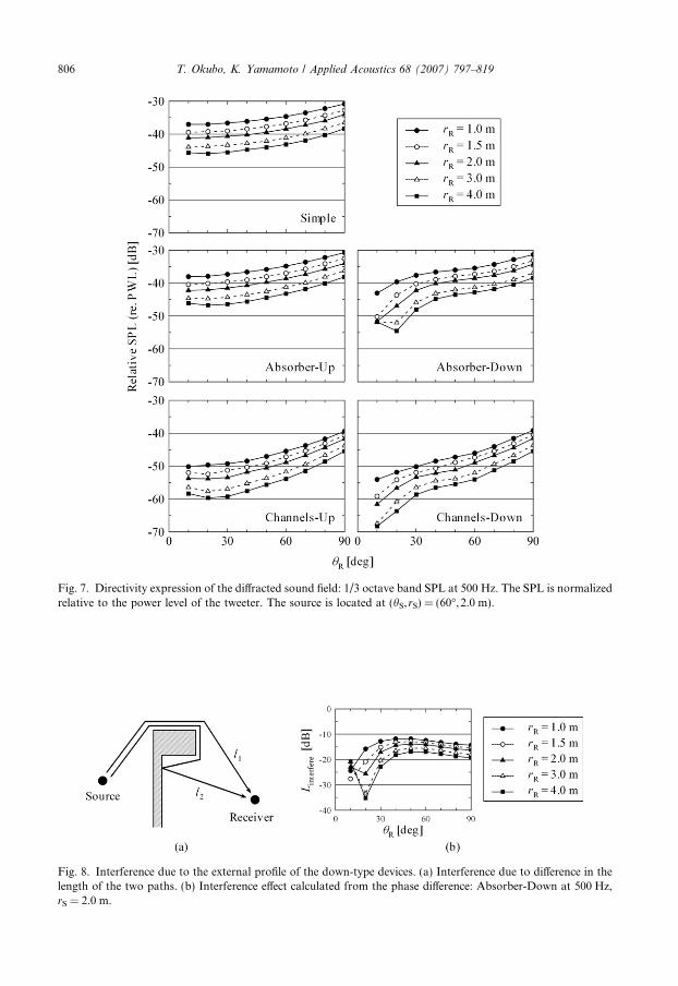
Fig. 7. Directivity expression of the diffracted sound field: 1/3 octave band SPL at 500 Hz. The SPL is normalizedrelative to the power level of the tweeter. The source is located at (hS,rS) = (60�, 2.0 m).
806 T. Okubo, K. Yamamoto / Applied Acoustics 68 (2007) 797–819
Fig. 8. Interference due to the external profile of the down-type devices. (a) Interference due to difference in thelength of the two paths. (b) Interference effect calculated from the phase difference: Absorber-Down at 500 Hz,rS = 2.0 m.

T. Okubo, K. Yamamoto / Applied Acoustics 68 (2007) 797–819 807
Linterfere ¼ 10log10
expðjkl1Þl1
þ expðjkl2Þl2
����
����
2
ð5Þ
where k is the wave number and l1 and l2 are the path lengths. This equation excludesattenuation due to diffraction. Fig. 8(b) shows Linterfere calculated for l1 and l2 definedaround the Absorber-Down profile. The calculated dips of Linterfere correspond to thosein the measurement results; the curves for rR = 3.0 and 4.0 m exhibit a dip at hR = 20�,while those for rR = 1.0 and 1.5 m decrease towards hR = 10�. This confirms the hypoth-esis shown in Fig. 8(a); therefore, the SPL dips represent the inevitable interference due tothe external profiles of down-type devices. In other words, the SPL dips are independent ofthe acoustic nature of the top surface of the device. Similar interference due to the up-typeprofile is discussed in the following section.
3.4. Efficiency of the edge devices
In this section, we discuss the edge device efficiencies DLedge,down(hS,hR, f) andDLedge,up(hS,hR, f). The measured efficiency of Absorber-Down is shown in Fig. 9. Graphsare arrayed into 4 columns for hS and rS and 9 rows for the 1/3 octave band frequency.DLedge,down(hS,hR, f) is plotted along the vertical axis as a function of hR, and 5 curves plot-ted in each graph correspond to the 5 values of rR. The results indicate that the deviationof DLedge,down(hS,hR, f) at different radii is small in the range of hR P 40�. However, whenhR 6 30�, the interference due to the external profile causes a large deviation, resulting inthe overestimation of the edge efficiency.
Fig. 10 shows the measured efficiency of Absorber-Up. In contrast to the resultsobtained for Absorber-Down, the deviation at different radii is small even in the rangeof small values of hR. This is mainly because the interference due to the external profiledisappears on the receiver side. With respect to the source position, the deviations forhS = 30� are larger than those for hS = 60�. This is possibly because the S/N ratio inthe measurements decreases due to a decrease in diffraction and an increase in transmis-sion through the barrier. DLedge,up(hS,hR, f) gradually increases towards zero with hR. Inthe results obtained for hS = 30�, a slight difference between DLedge,up(hS,hR, f) for twovalues of rS is observed at some frequencies. At 500 Hz, 630 Hz, and 1.2 kHz,DLedge,up(hS,hR, f) for rS = 2.0 m is greater than that for rS = 4.0 m by 2 dB, while it issmaller by 2 dB at 1 kHz. These differences are almost constant for all values of hR.The frequency characteristics indicate that the efficiency is quite large from 200 Hz to500 Hz. It seems unreasonable to obtain an efficiency of more than 5 dB at 250 Hz,despite the small absorption coefficient (approximately 0.2) of the felt fabric. In this case,we assume that these results are inconsistent due to the interference around the up-typeexternal profile, as shown in Fig. 11(a). The interference effect can be estimated againusing Linterfere in Eq. (5). Linterfere estimated for the external profile of Absorber-Up isshown in Fig. 11(b) for rS = 2.0 and 4.0 m with hS fixed at 30�. It is indicated thatthe decrease in Linterfere in the broad frequency range of 200–500 Hz leads to the over-estimation of the Absorber-Up efficiency. Further, Linterfere differs for two values of rS.Linterfere for rS = 2.0 m is greater than that for rS = 4.0 m at 500 Hz, 630 Hz, and1.2 kHz, while it is inversely smaller at 1 kHz. This relationship corresponds to the edgeefficiency described above.
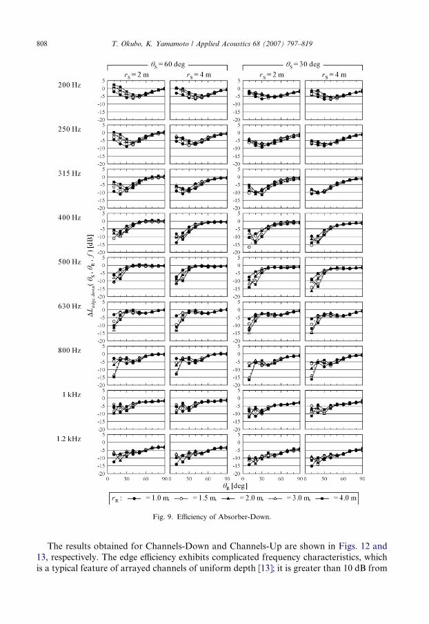
Fig. 9. Efficiency of Absorber-Down.
808 T. Okubo, K. Yamamoto / Applied Acoustics 68 (2007) 797–819
The results obtained for Channels-Down and Channels-Up are shown in Figs. 12 and13, respectively. The edge efficiency exhibits complicated frequency characteristics, whichis a typical feature of arrayed channels of uniform depth [13]; it is greater than 10 dB from
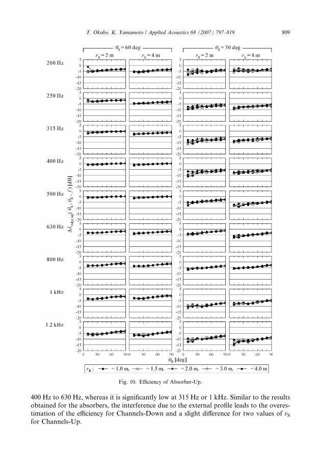
Fig. 10. Efficiency of Absorber-Up.
T. Okubo, K. Yamamoto / Applied Acoustics 68 (2007) 797–819 809
400 Hz to 630 Hz, whereas it is significantly low at 315 Hz or 1 kHz. Similar to the resultsobtained for the absorbers, the interference due to the external profile leads to the overes-timation of the efficiency for Channels-Down and a slight difference for two values of rS
for Channels-Up.
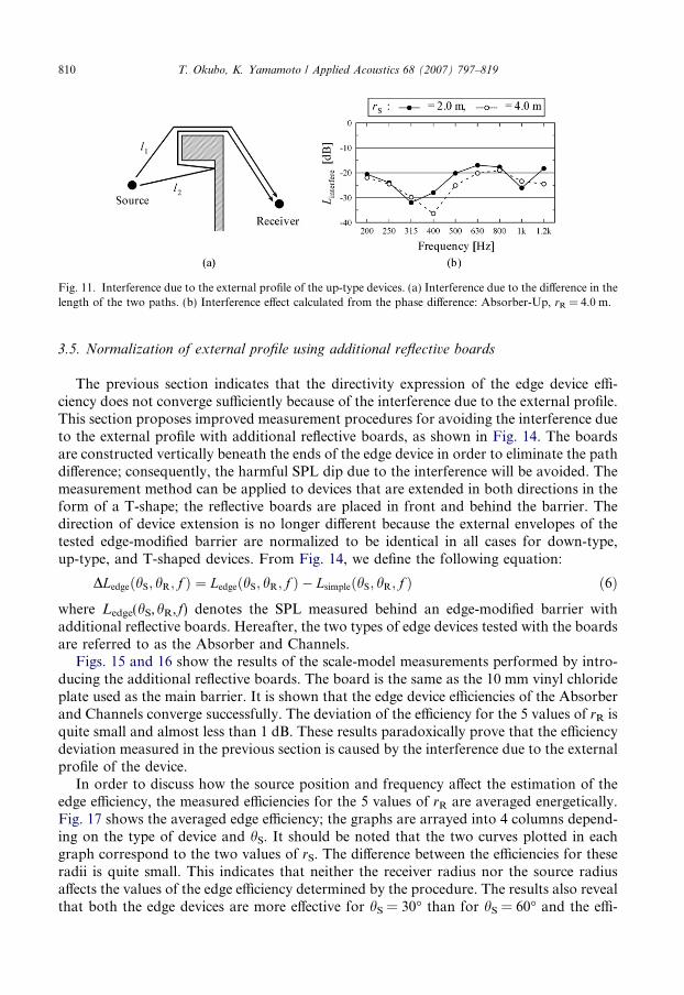
Fig. 11. Interference due to the external profile of the up-type devices. (a) Interference due to the difference in thelength of the two paths. (b) Interference effect calculated from the phase difference: Absorber-Up, rR = 4.0 m.
810 T. Okubo, K. Yamamoto / Applied Acoustics 68 (2007) 797–819
3.5. Normalization of external profile using additional reflective boards
The previous section indicates that the directivity expression of the edge device effi-ciency does not converge sufficiently because of the interference due to the external profile.This section proposes improved measurement procedures for avoiding the interference dueto the external profile with additional reflective boards, as shown in Fig. 14. The boardsare constructed vertically beneath the ends of the edge device in order to eliminate the pathdifference; consequently, the harmful SPL dip due to the interference will be avoided. Themeasurement method can be applied to devices that are extended in both directions in theform of a T-shape; the reflective boards are placed in front and behind the barrier. Thedirection of device extension is no longer different because the external envelopes of thetested edge-modified barrier are normalized to be identical in all cases for down-type,up-type, and T-shaped devices. From Fig. 14, we define the following equation:
DLedgeðhS; hR; f Þ ¼ LedgeðhS; hR; f Þ � LsimpleðhS; hR; f Þ ð6Þwhere Ledge(hS,hR, f) denotes the SPL measured behind an edge-modified barrier withadditional reflective boards. Hereafter, the two types of edge devices tested with the boardsare referred to as the Absorber and Channels.
Figs. 15 and 16 show the results of the scale-model measurements performed by intro-ducing the additional reflective boards. The board is the same as the 10 mm vinyl chlorideplate used as the main barrier. It is shown that the edge device efficiencies of the Absorberand Channels converge successfully. The deviation of the efficiency for the 5 values of rR isquite small and almost less than 1 dB. These results paradoxically prove that the efficiencydeviation measured in the previous section is caused by the interference due to the externalprofile of the device.
In order to discuss how the source position and frequency affect the estimation of theedge efficiency, the measured efficiencies for the 5 values of rR are averaged energetically.Fig. 17 shows the averaged edge efficiency; the graphs are arrayed into 4 columns depend-ing on the type of device and hS. It should be noted that the two curves plotted in eachgraph correspond to the two values of rS. The difference between the efficiencies for theseradii is quite small. This indicates that neither the receiver radius nor the source radiusaffects the values of the edge efficiency determined by the procedure. The results also revealthat both the edge devices are more effective for hS = 30� than for hS = 60� and the effi-

Fig. 12. Efficiency of Channels-Down.
T. Okubo, K. Yamamoto / Applied Acoustics 68 (2007) 797–819 811
ciency of the Absorber increases moderately with frequency. These characteristics of theefficiency correspond to the well-known characteristics of edge devices. Thus, it can beexplicitly concluded that the measurement procedure reveals the intrinsic efficiency ofthe devices.
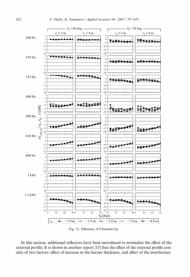
Fig. 13. Efficiency of Channels-Up.
812 T. Okubo, K. Yamamoto / Applied Acoustics 68 (2007) 797–819
In this section, additional reflectors have been introduced to normalize the effect of theexternal profile. It is shown in another report [15] that the effect of the external profile con-sists of two factors: effect of increase in the barrier thickness, and effect of the interference.
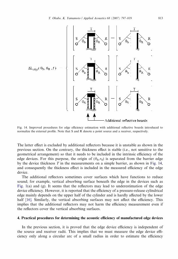
Fig. 14. Improved procedures for edge efficiency estimation with additional reflective boards introduced tonormalize the external profile. Note that S and R denote a point source and a receiver, respectively.
T. Okubo, K. Yamamoto / Applied Acoustics 68 (2007) 797–819 813
The latter effect is excluded by additional reflectors because it is unstable as shown in theprevious section. On the contrary, the thickness effect is stable (i.e., not sensitive to thegeometrical arrangement) so that it needs to be included in the intrinsic efficiency of theedge devices. For this purpose, the origin of (hS, rS) is separated from the barrier edgeby the device thickness T in the measurements on a simple barrier, as shown in Fig. 14,and consequently the thickness effect is included in the measured efficiency of the edgedevice.
The additional reflectors sometimes cover surfaces which have functions to reducesound; for example, vertical absorbing surface beneath the edge in the devices such asFig. 1(a) and (g). It seems that the reflectors may lead to underestimation of the edgedevice efficiency. However, it is reported that the efficiency of a pressure-release cylindricaledge mainly depends on the upper half of the cylinder and is hardly affected by the lowerhalf [16]. Similarly, the vertical absorbing surfaces may not affect the efficiency. Thisimplies that the additional reflectors may not harm the efficiency measurement even ifthe reflectors cover the vertical absorbing surfaces.
4. Practical procedures for determining the acoustic efficiency of manufactured edge devices
In the previous section, it is proved that the edge device efficiency is independent ofthe source and receiver radii. This implies that we must measure the edge device effi-ciency only along a circular arc of a small radius in order to estimate the efficiency
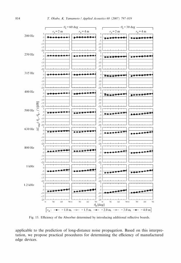
Fig. 15. Efficiency of the Absorber determined by introducing additional reflective boards.
814 T. Okubo, K. Yamamoto / Applied Acoustics 68 (2007) 797–819
applicable to the prediction of long-distance noise propagation. Based on this interpre-tation, we propose practical procedures for determining the efficiency of manufacturededge devices.
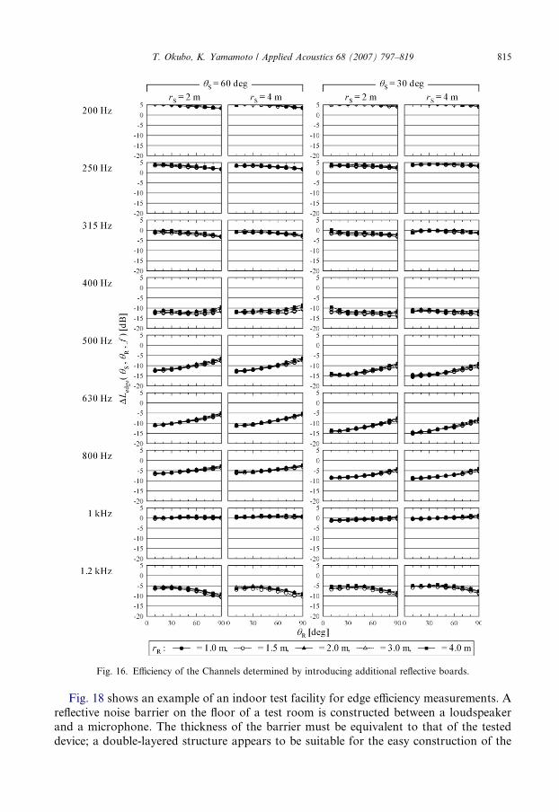
Fig. 16. Efficiency of the Channels determined by introducing additional reflective boards.
T. Okubo, K. Yamamoto / Applied Acoustics 68 (2007) 797–819 815
Fig. 18 shows an example of an indoor test facility for edge efficiency measurements. Areflective noise barrier on the floor of a test room is constructed between a loudspeakerand a microphone. The thickness of the barrier must be equivalent to that of the testeddevice; a double-layered structure appears to be suitable for the easy construction of the
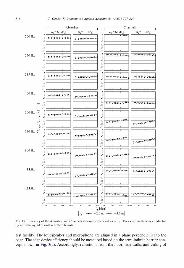
Fig. 17. Efficiency of the Absorber and Channels averaged over 5 values of rR. The experiments were conductedby introducing additional reflective boards.
816 T. Okubo, K. Yamamoto / Applied Acoustics 68 (2007) 797–819
test facility. The loudspeaker and microphone are aligned in a plane perpendicular to theedge. The edge device efficiency should be measured based on the semi-infinite barrier con-cept shown in Fig. 3(a). Accordingly, reflections from the floor, side walls, and ceiling of

Fig. 18. Example of an indoor test facility for the determination of the edge efficiency.
Fig. 19. Example of measurement results tabulated in a spreadsheet format; the edge device efficiency is expressedas a function of the angles and frequency.
T. Okubo, K. Yamamoto / Applied Acoustics 68 (2007) 797–819 817
the test room should be eliminated to extract only the direct diffraction over the edge. Theefficiency is measured for different combinations of hS and hR at certain intervals along acircular arc of fixed rS and rR. The radii can be small, e.g. 1.0 m. The measurement results

818 T. Okubo, K. Yamamoto / Applied Acoustics 68 (2007) 797–819
are tabulated as a function of the angles and frequency. A tabulated database in a spread-sheet format, as shown in Fig. 19, will be useful for predicting outdoor noise propagation.
The dimensions of the test room should be configured carefully: vertical and horizontalclearances HC and DC, respectively, and barrier height HB. The test room must be suffi-ciently large for delaying unwanted reflections and preventing them outside the temporalextraction window. Regulations of the test room size and signal-processing techniquesdetailed in CEN/TS 1793–4 [5] can be diverted equivalently. HB, HC, and DC should begreater than 4 m for a temporal window specified in the CEN/TS.
The measurement can be performed in an outdoor test field. In general outdoor acous-tic measurements, we must pay careful attention to avoid meteorological effects such asthose of temperature, humidity, wind, and turbulence. However, meteorological effectsmay be small in the proposed procedure in which the propagation distance from a loud-speaker to a microphone is quite short (e.g. rS + rR = 2.0 m). Consequently, in the pro-posed procedure, these effects may require less attention than that in general outdoormeasurements.
5. Conclusions
A novel procedure for determining the efficiency of edge devices is validated by scalemodel experiments. The edge device efficiency is measured in an alignment along a circulararc centred on top of a barrier. Experimental results verify that the efficiency depends onthe angles of the source and receiver, while it is independent of their radii. The efficiencydetermined as a function of the angles converges with a very small deviation when addi-tional reflectors are introduced to avoid interference due to the external profile of thedevice.
The prediction of noise propagation by using the measured efficiency of edge devices isinvestigated in another paper [12]. By substituting the measured efficiency into each pathof the multiple-path method developed by Lam and Roberts [9], the model accurately pre-dicts both the interference due to ground reflection and the efficiency of the edge device. Asimilar procedure may be applied to the point-to-point attenuation model in the Harmo-noise engineering method [11].
The proposed determination method is based on measurements in the normal incidencealignment of the source and receiver, i.e. they are located in a plane perpendicular to thebarrier edge. In a practical sound field along road traffic, the efficiency in the non-normalincidence case must be investigated because a vehicle on the road moves parallel to thebarrier. It is already known that DLedge(hS,hR,f) of absorptive edge devices in any non-nor-mal alignment will be smaller than that in the normal incidence alignment [17]. Therefore,by applying the normal incidence efficiency to predictions for any non-normal alignment,we can avoid the underestimation of noise pollution along the road. It has not yet beenconfirmed whether the normal incidence efficiency for devices of the interference type oractively controlled type also avoids the underestimation of noise pollution.
Further investigation is required to regulate the applicable ranges of hS and hR for thedirectivity hypothesis. The hypothesis will be invalid at a certain limit of hR above 90�,although hS is always less than 90� in road traffic noise problems. The hypothesis is prob-ably true in the shadow region, i.e. hR < 180� � hS. Specifications for defining the centre ofthe measuring circular arc for circular devices, such as those in Fig. 1(a) or (b), are alsorequired.
T. Okubo, K. Yamamoto / Applied Acoustics 68 (2007) 797–819 819
References
[1] Fujiwara K, Furuta N. Sound shielding efficiency of a barrier with a cylinder at the edge. Noise Control EngJ 1991;37:5–11.
[2] Okubo T. Edge-modified noise barriers. J INCE Jpn 2004;28:317–22.[3] Ishizuka T, Fujiwara K. Performance of noise barriers with various edge shapes and acoustical conditions.
Appl Acoust 2004;65:125–41.[4] ISO 10847. Acoustics – in situ determination of insertion loss of outdoor noise barriers of all types; 1997.[5] CEN/TS 1793-4. Road traffic noise reducing devices – test method for determining the acoustic performance
– Part 4: Intrinsic characteristics – in situ values of sound diffraction, December; 2003.[6] Okubo T, Yamamoto K. Evaluation method for the efficiency of edge-improved noise barriers. In:
Proceedings of the 18th international congress acoustics, Kyoto, April; 2004. p. II-1031–4.[7] Bowman JJ, Senior TB, Uslenghi PLE. Electromagnetic and acoustic scattering by simple shapes.
Amsterdam: North-Holland Publishing; 1969.[8] Maekawa Z. Noise reduction by screens. Appl Acoust 1968;1:157–73.[9] Lam YW, Roberts SC. A simple method for accurate prediction of finite barrier insertion loss. J Acoust Soc
Am 1993;93:1445–52.[10] Yamamoto K, Yoshihisa K, Miyake T, Tajika T, Tachibana H. Road traffic noise prediction model ‘‘ASJ
RTN-model 2003’’ proposed by the Acoustical Society of Japan – Part 3: Calculation model of soundpropagation. In: Proceedings of the 18th international congress acoustics, Kyoto, April; 2004. p. IV-2797–800.
[11] Harmonoise WP3 Engineering method for road traffic and railway noise after validation and fine-tuning.Technical Report HAR32TR-040922-DGMR20; 2005.
[12] Okubo T, Yamamoto K. A simple prediction method for sound propagation behind edge-modified barriers.Acoust Sci Tech [in press].
[13] Fujiwara K, Hothersall DC, Kim CH. Noise barriers with reactive surfaces. Appl Acoust 1998;53:255–72.[14] Suzuki Y, Asano F, Kim HY, Sone T. An optimum computer-generated pulse signal suitable for the
measurement of very long impulse responses. J Acoust Soc Am 1995;97:1119–23.[15] Okubo T, Yamamoto K. Noise shielding efficiency of barriers with eaves. In: Proceedings of 2006 spring
meeting, Acoustical Society of Japan. p. 743–4.[16] Okubo T, Fujiwara K. Efficiency of a noise barrier with an acoustically soft cylindrical edge for practical use.
J Acoust Soc Am 1999;105:3326–35.[17] Inoue M, Fujiwara K. Effective length of absorptive cylinder installed on the edge of a barrier. In:
Proceedings of the Kyushu–Youngnam joint conference on acoustics; 2003. p. 113–6.


![Experimental substantiation of acoustic method for determination of “coal … · acoustic methods of mine geophysics [12, 13]. In the present work, the method for determining contact](https://img.dokumen.tips/doc/110x75/5fa6d3539251bb3574619f60/experimental-substantiation-of-acoustic-method-for-determination-of-aoecoal-acoustic.jpg)