Embed Size (px)
Citation preview

Procedure to Install a CIM Door Retrofit in an Existing Airbath/Airless Maxum II (with SYSCON2) Difficulty Level: Medium Estimated time to execute: 2 Hours Revision History Issue Date Reason 00A 6/28/12 Beta Draft 00B 8/1/12 Modify power connections 001 8/6/12 Lab Tested 002 8/18/12 Minor changes. Change document number. 003 8/20/12 Update images. 004 8/28/12 Update based on review. 005 8/29/12 Minor change. 006 10/11/12 Changes based on beta results 007 12/13/12 Change error in image. Break out sections.
CIM Door Upgrade Page 1 IP-0020 Maxum II SYSCON2

1.0 Description This document describes the procedure to replace an original version Maxum II door with a CIM (Control Interface Module) door. The primary purpose of this retrofit is to incorporate the CIM display. This display is a color screen user interface with touch pad control and is designed to be a greatly enhanced replacement for the legacy HMI (Human Machine Interface) available for the Maxum II. The CIM display represents a large leap forward in usability over the HMI. Beyond the addition of color and touch screen technology, the CIM display utilizes a much larger display area and provides enhanced graphics and on-screen help functions. In addition to the enhanced user display, the CIM door contains the CIM electronics modules used to control the display. The CIM electronics are capable of performing several functions within the Maxum, including being the processor for a Modular Oven Configuration Maxum II. This procedure involves installation of CIM hardware for use as a user display. For more information on the CIM display and electronics hardware, refer to the Maintenance Manual for the Modular Oven Maxum. Note: This document is specific to Maxum II analyzers configured with SYSCON2. For Maxum II analyzers configured with SYSCON1/SYSCON+, refer to the appropriate procedure (IP-0021).
Figure 1: CIM Display
CIM Door Upgrade Page 2 IP-0020 Maxum II SYSCON2

Caution: This upgrade involves multiple steps, several of which MUST be
performed in the correct order will. Failure to follow all of the steps in this procedure in the correct order will result in the upgrade failing or the analyzer not working correctly afterwards. This procedure must be executed by personnel who have the knowledge necessary to complete all the required software and hardware steps. If the user needs help with completing this procedure then it is recommended that Siemens Field Service personnel be contracted to assist.
This upgrade involves multiple steps that must be performed in the correct order. The basic steps are as follows. Refer to the diagrams on the following pages. 1. Install Gas Chromatograph Portal workstation software (version 5.10) and
System Manager software (version 5.0.19), if not already installed. 2. Upgrade the analyzer to Release 5.10 and the SYSCON OS and Boot firmware,
if not already installed. 3. Modify analyzer IP addresses to support the retrofit. 4. Power down the analyzer and perform hardware installation. 5. Configure the IP address and operating mode for the new CIM. 6. Upgrade the SYSCON software to function with new IP configuration. 7. Verify the operation of the new hardware.
SYSCON2
CAC3
External Ethernet
ESB
HMI
Door Figure 2: Diagram of Ethernet and User Display Connections
Starting Configuration
CIM Door Upgrade Page 3 IP-0020 Maxum II SYSCON2

InternalEthernet
SYSCON2
CAC3
External Ethernet
ESB
CIM
CAC3
External Ethernet
CIM Touch Screen Color Display
Door
Figure 3: Diagram of Ethernet and User Display Connections Final Configuration
CIM Door Upgrade Page 4 IP-0020 Maxum II SYSCON2

2.0 Prerequisites
• This procedure must be performed by a user who has detailed knowledge of the Maxum. This includes detailed knowledge of the hardware and operation of the device. In addition, the user should have sufficient computer skills to be able to install and operate the Gas Chromatograph Portal software. If a customer does not have the knowledge required for this procedure, then it is recommended that Siemens Field Service personnel be contracted to assist.
• The analyzer must be a Maxum II equipped with SYSCON2. Installation in
Advance Maxum analyzers is not supported at this time. For Maxum II analyzers equipped with SYSCON1/SYSCON+, refer to the relevant procedure (IP-0021).
• A tool kit including both standard and metric wrenches, Hex wrenches, and
screw drivers is required to perform this procedure
Warning: Full safety precautions must be followed throughout all sections of this procedure to prevent possible injury, equipment damage, or death. Verify that the area is clear of flammable gases and vapors and that appropriate authorization is obtained to do the work (hot work permits).
A retrofit kit (part number A5E31317779001) is required for this procedure. The kit contains the following items.
Description Quantity Door assembly with installed CIM display and CIM-Board (CIM-Board consists of the base board with installed CAC3) 1 Serial cable (for connection from SYSCON Debug to CIM Serial port) 1 “Y-shaped” Purge Cable (for splitting purge signal cable from PECM). 1 Green Ethernet cable (for connecting CIM CAC3 to ESB) 1 Short Gray Ethernet cable (for connecting SYSCON1/+ to CIM-Base) 1 Long Gray Ethernet cable (for connecting SYSCON2 to CIM-Base) 1 Gray Ethernet cable (for connecting SYSCON2 CAC3 to CIM-Base) 1 Power Wire for CIM I2C (white) connector to 24V (black) connector 1 Intrinsic Safety (IS) Ground wires for CIM 2
Note: The above list is included for reference only and is not intended to be all
inclusive. For a complete list with part numbers, refer to the packing list sent with the kit.
CIM Door Upgrade Page 5 IP-0020 Maxum II SYSCON2

3.0 CIM and SYSCON Connections This section provides figures showing the available connections for the CIM and SYSCON2.
Figure 4 – SYSCON2 Board Connections
CIM Door Upgrade Page 6 IP-0020 Maxum II SYSCON2
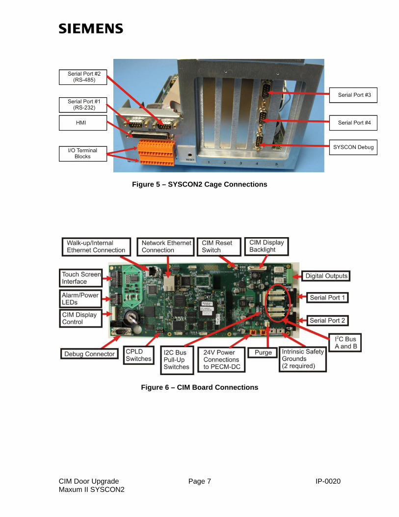
Figure 5 – SYSCON2 Cage Connections
Figure 6 – CIM Board Connections
CIM Door Upgrade Page 7 IP-0020 Maxum II SYSCON2

4.0 Install/Upgrade Gas Chromatograph Portal Software (if Needed) This section covers installing/upgrading of the workstation software. This is required to support the various retrofit tasks later in the procedure.
Step Procedure
Note: For additional information relating to the installation and use of Gas
Chromatograph Portal (GCP), refer to the Getting Started Manual for GCP (part number A5E03944542001).
Note: This section is not required if the software was installed previously.
1. Gas Chromatograph Portal (GCP) Software for Maxum Version 5.10 is required. To upgrade the GCP software, insert the Maxum Software installation disk. The installation program should launch automatically.
2. From the menu, select the System Manager Setup Wizard.
3. Following the instructions on the screen, use the Setup Wizard to upgrade the System Manager Software to the required version 5.0.19.
4. After System Manager is upgraded, select the GCP Setup Wizard from the
installation menu in order to upgrade the Gas Chromatograph Portal Software to the required version 5.10.
5. The Setup Wizard will determine if any additional windows packages are
necessary and install them automatically. If system prompts for reboot, then do so before continuing. Otherwise, the GCP installation may not complete properly.
6. Continue the installation, answering any prompts from the screen. It is
recommended that default options be selected.
7. Repeat the installation for all computers that you wish to upgrade.
CIM Door Upgrade Page 8 IP-0020 Maxum II SYSCON2

5.0 Upgrade Maxum to Version 5.10 (if Needed) This section covers upgrading the Maxum II to software version 5.10, along with upgrading the SYSCON2 OS and Bootloader, which is a requirement for communication with the CIM.
Step Procedure
Note: This section is not required if the software was installed previously. Note: This section requires use of the Gas Chromatograph Portal (GCP)
software. For additional information relating to use of GCP, refer to the Getting Started Manual for GCP (part number A5E03944542001).
1. To upgrade, open the GCP Network portal and choose the correct analyzer.
Then choose the Software Upgrade button at the top of the window. After logging in, the window below is displayed.
If all applications are not already in hold, then place them in hold at this time using the “Hold all Applications” button, and then wait for all currently running cycles to complete. Verify that “Upgrade5.10” is selected. The upgrade tool will determine based on the existing configuration and the target version which items to upgrade (which can be seen with the “Show Details” button, if desired).
CIM Door Upgrade Page 9 IP-0020 Maxum II SYSCON2

Step Procedure
2. Hit OK to begin the upgrade. The upgrade will take several minutes, during
which time a series of messages detailing the progress of the upgrade will be displayed. Monitor for any errors. Note: At one point during the upgrade a DBConverter window will pop up. This is an automatic function of the upgrade script. No user intervention is necessary.
3. When the upgrade is finished, the following message should be displayed.
Click OK to continue.
Note that if the above window is not displayed then the upgrade may not have completed successfully.
CIM Door Upgrade Page 10 IP-0020 Maxum II SYSCON2

6.0 Modify IP Addresses for the SYSCON This section covers the final step before replacing the hardware. The IP addresses stored in the SYSCON must be modified to communicate with the CIM (after it is installed the CIM will be configured with the site specific IP address information for the analyzer).
Step Procedure
Note: With the CIM door installed, the CIM will control the IP communication
for the analyzer. In this configuration the SYSCON communicates with the CIM using a uniform set of IP settings. To change the SYSCON IP settings, all addresses must be set at the same time using the form in the HMI emulator for GCP. This is due to the fact that the device will no longer communicate on the LAN once one address is changed.
CAUTION: The steps in this section must be executed exactly as
described. Entering an incorrect IP address will make it impossible to communicate with the device after the upgrade.
Note: This section requires use of the Gas Chromatograph Portal (GCP)
software. For additional information relating to use of GCP, refer to the Getting Started Manual for GCP (part number A5E03944542001). This section also requires use of the HMI emulator. Since the software was upgraded, this will be the new emulator that looks the same as the CIM Display. More information on the use of this can be found in appendix 3 at the end of this procedure.
1. Open the HMI emulator for the device using the GCP software.
2. If the analyzer is not already in hold, put it in hold at this time (click Hold on the upper middle part of the emulator window).
3. On the HMI emulator select the Configure Menu and then select the
“System Setup” menu item. The Configure Menu is selected by choosing the icon in the lower right portion of the emulator window.
4. From the System Setup screen select “IP SET INFO” at the bottom of the
screen, and then choose “LAN 1 IP adr” from the table. Write down the LAN 1 IP Adr, the LAN 1 IP Mask, and the Router 1 IP Adr settings for later use. These will be programmed into the CIM.
CIM Door Upgrade Page 11 IP-0020 Maxum II SYSCON2

Step Procedure
Note: Entering an incorrect IP address in the following step will make
it impossible to communicate with the device after the upgrade without changing the address using the bootloader.
5. On the IP setting screen hit the “Modify” softkey. This will bring up the
following window.
Enter the numbers exactly as shown above and then click OK. These are settings that will be required to communicate with the CIM via internal IP bus.
6. Once the IP addresses have been changed, close the HMI emulator and
the GCP connection. Note that depending on the configuration and timing the software may freeze for several seconds while waiting for network response.
7. Continue with the next section, Analyzer Door Replacement, immediately.
CIM Door Upgrade Page 12 IP-0020 Maxum II SYSCON2

7.0 Analyzer Door Replacement This section covers replacing the original door with the new CIM door. Refer to figures 4-6 in the previous section for connection locations.
Step Procedure
Warning: Full safety precautions must be followed throughout this
procedure to prevent possible injury, equipment damage, or death. Verify that the area is clear of flammable gases and vapors and that appropriate authorization is obtained to do the work.
1. Using appropriate safety precautions, power down the analyzer.
2. After appropriate safety precautions have been followed, open the door to the Electronics Enclosure (EC)
3. Unscrew the two nuts that secure the SYSCON2 cage, and pull the cage
out to the dropped-down position as shown below.
CIM Door Upgrade Page 13 IP-0020 Maxum II SYSCON2

Step Procedure
4. Disconnect the HMI cable from the back of the SYSCON2 board. Push the
tabs at the sides of the black connector together as shown below to unlock the connector.
Clips Secured Clips Pressed to Remove Disconnect the HMI cable from any clips that affix the cable to the EC. Leave the cable plugged into the HMI.
CIM Door Upgrade Page 14 IP-0020 Maxum II SYSCON2

Step Procedure
5. Remove the ground lugs from the door end. These will be reused on the
new door.
6. If equipped, remove the HMI to EC ground wire at the EC end. This wire will
not be reused.
CIM Door Upgrade Page 15 IP-0020 Maxum II SYSCON2
Step Procedure
7. Remove door by lifting off hinges.
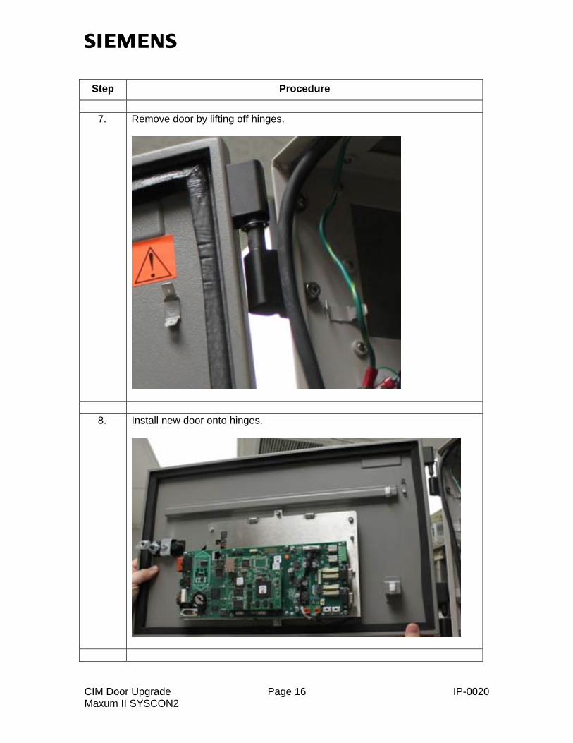
8. Install new door onto hinges.
CIM Door Upgrade Page 16 IP-0020 Maxum II SYSCON2

Step Procedure
9. Remove the purge cable running from the SYSCON2 to the PECM.
SYSCON End
PECM End
CIM Door Upgrade Page 17 IP-0020 Maxum II SYSCON2

Step Procedure
Note: In some older versions of analyzer there may be a short connector wire
installed in line with the original purge cable running to the SYSCON (see below). This is a purge bypass cable used to disable the purge alarm. If this is installed it should remain installed in the same location. The SYSCON end of the Y-shaped cable will plug into the bypass cable.
10. On the new CIM, verify that the switch settings are correct. CPLD Spare
switches should all be Off (down). The I2C Bus Pull-Up switches should all be On (to the left).
CIM Door Upgrade Page 18 IP-0020 Maxum II SYSCON2

Step Procedure
11. Connect Y-shaped purge cable from PECM to both CIM and SYSCON2.
CIM End
PECM End
SYSCON End
CIM Door Upgrade Page 19 IP-0020 Maxum II SYSCON2

Step Procedure
12. Remove the short Ethernet cable that runs from the CAC3 on the
SYSCON2 to the ESB board.
Note: In the following steps the Ethernet cables are to be routed along the back of
SYSCON2 cage and then down the back of the Electronics Enclosure (EC). Cables are then routed to the left and by the PECM and then forward as shown below.
CIM Door Upgrade Page 20 IP-0020 Maxum II SYSCON2

Step Procedure
13. Install the long gray Ethernet cable from the kit, plugging it into the CAC3
on the SYSCON2 and the RJ-45 connector on the CIM-Base board.
SYSCON2 End
CIM End
CIM Door Upgrade Page 21 IP-0020 Maxum II SYSCON2
Step Procedure
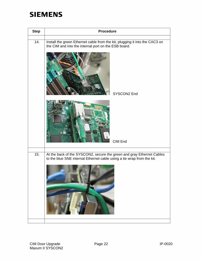
14. Install the green Ethernet cable from the kit, plugging it into the CAC3 on
the CIM and into the internal port on the ESB board.
SYSCON2 End
CIM End
15. At the back of the SYSCON2, secure the green and gray Ethernet Cables
to the blue SNE internal Ethernet cable using a tie wrap from the kit.
CIM Door Upgrade Page 22 IP-0020 Maxum II SYSCON2
Step Procedure
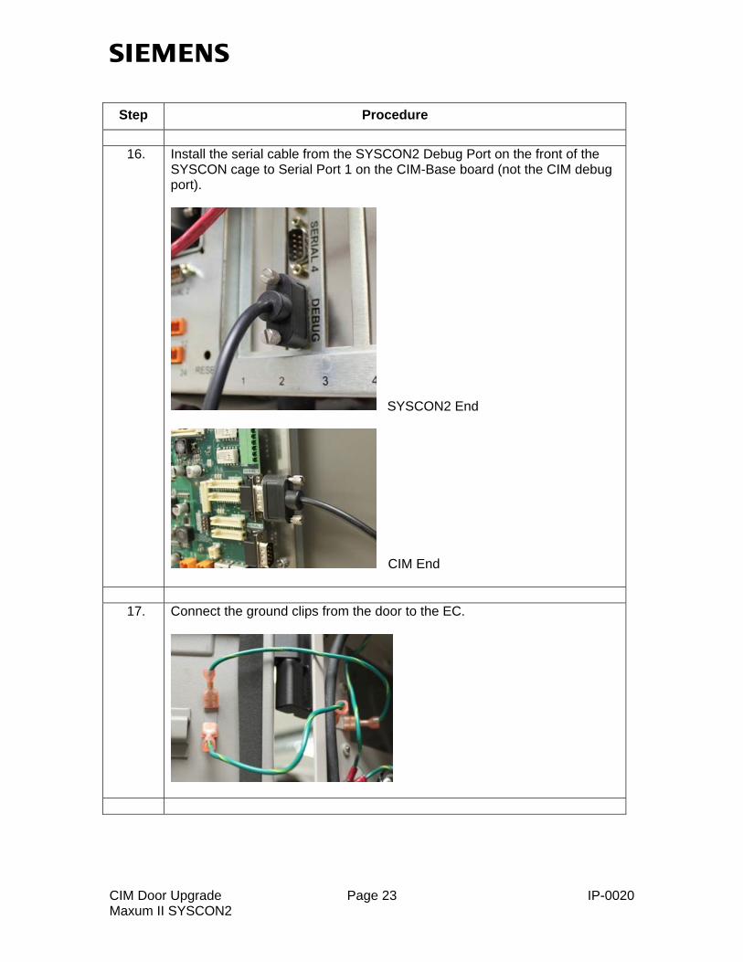
16. Install the serial cable from the SYSCON2 Debug Port on the front of the
SYSCON cage to Serial Port 1 on the CIM-Base board (not the CIM debug port).
SYSCON2 End
CIM End
17. Connect the ground clips from the door to the EC.
CIM Door Upgrade Page 23 IP-0020 Maxum II SYSCON2
Step Procedure
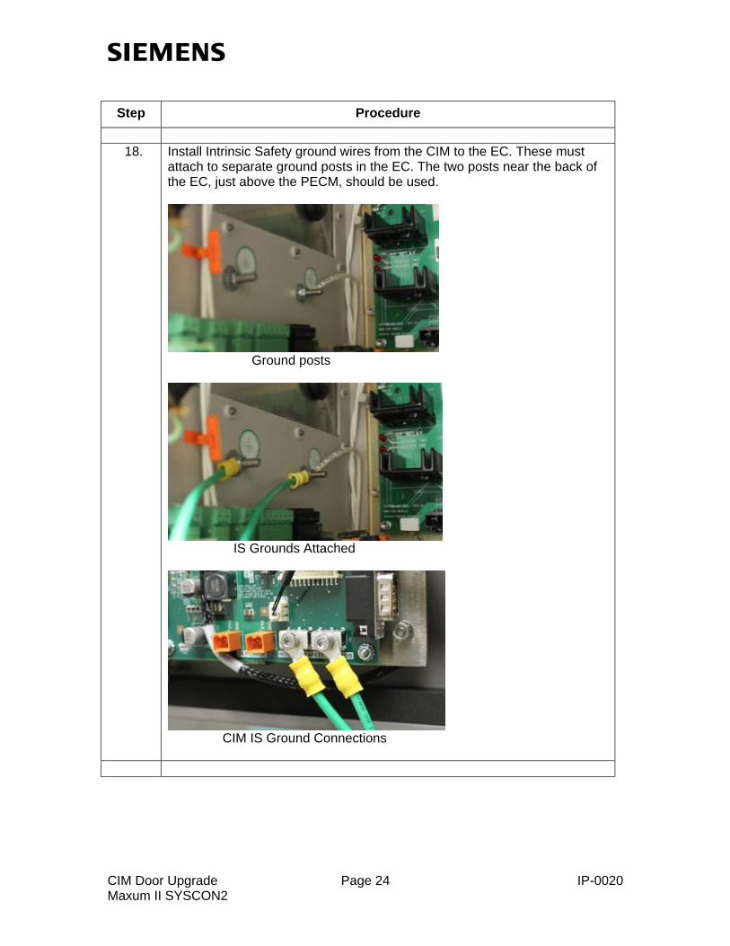
18. Install Intrinsic Safety ground wires from the CIM to the EC. These must
attach to separate ground posts in the EC. The two posts near the back of the EC, just above the PECM, should be used.
Ground posts
IS Grounds Attached
CIM IS Ground Connections
CIM Door Upgrade Page 24 IP-0020 Maxum II SYSCON2

Step Procedure
Note: Power wiring for the CIM door is accomplished using a specially designed
cable (see below) that plugs into a free WDB I2C connector. This differs slightly from power for a CIM that is shipped with a new analyzer. The retrofit is done in this manner in order for the door to be compatible with all legacy power configurations (such as PECM1).
19. Power connection at WDB end:
Plug the white I2C connector of the power cable into any unused WDB I2C connection.
Empty Connector Power Cable Connected
Note: As with the Ethernet cables, the power cable runs across the back of the EC and
then towards the front, adjacent to the PECM.
CIM Door Upgrade Page 25 IP-0020 Maxum II SYSCON2

Step Procedure
20. Power connection at CIM end:
Run the other end of the power cable to the CIM and plug it into the P2 power connector (left connector) on the CIM.
21. Secure all cables to the cable tie bracket on the CIM door.
22. Before powering up the device, temporarily unplug the green Ethernet cable
from the CIM. This is to prevent the device from possibly broadcasting the default IP address of the CIM on the network.
CIM Door Upgrade Page 26 IP-0020 Maxum II SYSCON2

8.0 Configure IP Addresses and Operating Mode
Step Procedure Note: The following steps require the user to enter the bootloader menu on the
CIM display. This menu is accessible at the time of power up. The IP settings and the CIM Device Mode need to be set.
1. Apply power to the analyzer. The startup screen should appear on the CIM
display.
2. Wait for the message “To enter the bootloader menu, press the Home key now”. At that point press the Home key on the screen and the boot menu should appear.
3. Choose selection 5 (Configuration...) on the bootloader menu.
4. To change the IP settings press 2 on the Configuration menu (Primary Ethernet IP Configuration). The system will proceed with a list of questions. Read each question carefully and follow the instructions to questions on the screen to change the IP settings. These are the customer specific IP settings that were set for the SYSCON2 before the SYSCON2 IP settings were changed. Note: At this time only change the IP Address, the Subnet Mask (if different), and the Default Gateway Address. After entering an address, the Home key is used as an Enter key to accept the change.
5. The Device Mode identifies if the CIM is operating as a user display or as
the control module for an analyzer. To change the Device Mode press selection 4 (Choose device mode) on the bootloader Configuration Menu. Set the mode for the CIM to operate as a touch screen display for the SYSCON2 (“User Interface connected to SYSCON2”). At this point the CIM will reboot automatically
Note: Although the IP settings are now correct, they will not display correctly if the
user tries to display them on the new CIM display (the internal settings for the SYSCON will be displayed). The step on the next page must be completed first.
6. Now that the IP settings for the CIM are correct, plug the green Ethernet
cable back into the CIM.
7. Allow the analyzer to reboot and allow it to come up.
CIM Door Upgrade Page 27 IP-0020 Maxum II SYSCON2

9.0 Upgrade SYSCON Software to Function with New CIM
Step Procedure
Note: Although it may appear that the analyzer is communicating, not all
communications and IP configurations are functional yet (for example, the display will only show the internal SYSCON IP settings rather than the correct network IP settings). At this point the user must update the SYSCON so that the database can correctly operate with the new IP settings as shown in the following step.
1. This step updates the SYSCON so that it will correctly identify that it is
working on an internal network through the CIM. Open the GCP Network portal and highlight the line for the correct analyzer. Then choose the Software Upgrade button at the top of the window. After logging in, the upgrade window is displayed. Choose the “Show Details” button. The window below should be displayed. Uncheck all items except “Database Scripts”. Then click OK. The upgrade window should appear. Monitor the status and verify the process completes successfully.
CIM Door Upgrade Page 28 IP-0020 Maxum II SYSCON2

10.0 Verify Operation
Step Procedure
1. Verify that the purge alarm LED and all other LEDs work as expected.
• If the analyzer is set up for purge alarm, then when the purge
pressure is lost (door open), the alarm LED should be flashing. The LED should turn off when the door is closed and the electronics enclosure has purge pressure.
• If the analyzer is set up to bypass the purge alarm, then the LED should not be lit when the door is open.
2. Verify that the CIM display works as expected. Refer to Appendix 3 on page
34 for instructions relating to use of the CIM display.
• Access a table, such as the Temperature Controller table. This can be done by tapping the icon labeled “Temp” on the right side of the screen.
• Access the context sensitive Help, but touching the help icon ( ) on the upper right corner of the CIM display. Then, touch another item on the screen, such as a menu selection. A dialog box shoappear that displays information about the item.
uld
• Verify the IP addresses for the analyzer. This can be done by choosing the icon labeled “Configure” on the lower right hand side of the screen. This brings up the Configure menu. Then tap the “System Setup” menu item and choose the “IP Set Info” softkey. Verify that the IP addresses are correct.
3. Verify the time on the analyzer is correct. During the upgrade it is possible that the time may shift by an hour or more. If the analyzer is configured to obtain date and time information from a central server, then it will update automatically. If no time server is set, it may be necessary to manually set the date and time on the analyzer.
4. Verify that you can communicate to the analyzer via all external
connections that are defined (e.g. GCP, Modbus, I/O). Verify that network broadcasts are received correctly.
5. Put the analyzer back in Run and verify that all other operations are
working as expected.
CIM Door Upgrade Page 29 IP-0020 Maxum II SYSCON2

Appendix 1: Troubleshooting Tips This appendix provides the user with several possible faults that could occur with the installation of the new door, along with possible causes.
Symptom Possible Causes Possible Corrective Action CIM Display will not come up.
Depending on the failure this may be due to faulty or incorrectly installed hardware.
Check that the CIM CAC3 board is properly seated, that the power connections are properly made, and that all other cable connections are correct.
CIM Display will not connect to analyzer.
1. Analyzer is not connected correctly or faulty. 2. Analyzer is not active 3. IP Addresses on the SYSCON are incorrect.
1. Verify that the Ethernet cable is connected correctly as described in the procedure. 2. Verify that the SYSCON2 is running correctly by checking the LEDs on the board (refer to the Installation Manual for the SYSCON2) 3. Try resetting the CIM using the reset button on that board. 4. There is a “Connect to Debug” option on the connection screen. This will allow the user to see the output of the Debug port of the SYSCON. Contact Customer Support for assistance.
CIM Display connects to analyzer but time does not update.
Database is not operating correctly, possibly because the upgrade to version 5.10 did not complete successfully.
Verify that the database is at the correct version. Contact Customer Support for assistance.
No communication to analyzer on network
1. Ethernet cable from CIM to ESB not plugged in correctly or is faulty. 2. IP address for the CIM not set correctly
1. Verify the Ethernet cable is connected correctly as described in the procedure. 2. Using the CIM display, verify the external IP settings are the same as prior to replacing the door. Try resetting the analyzer.
Partial or incorrect communication on network
The database IP configuration file was not up updated or is incorrect.
Verify that the upgrade step at the end of the procedure was completed correctly. This step sets the database to correctly deal with the internal SYSCON IP settings. Contact Customer Support for assistance.
Purge LEDs or alarm not functioning correctly.
New purge cable not connected correctly or is faulty.
Verify cable is connected correctly at all three locations: PECM, CIM, and SYSCON. Note that both the CIM and SYSCON ends are identical and should be interchangeable. The lead connecting to the SYSCON controls the purge alarm in software. The lead connecting to the CIM controls the purge alarm LED on the door.
CIM Door Upgrade Page 30 IP-0020 Maxum II SYSCON2

Appendix 2: Fallback Procedure This appendix covers the basic procedure to fall back to the original Maxum door if the new CIM door is not functioning correctly. If possible the user should first try to troubleshoot the new door before resorting to reinstalling the original door. It is advisable that Siemens support be contacted prior to fallback.
Step Procedure
Warning: Full safety precautions must be followed throughout this
procedure to prevent possible injury, equipment damage, or death. Verify that the area is clear of flammable gases and vapors and that appropriate authorization is obtained to do the work.
Note: Fallback involves removing the new CIM door and reinstalling the original
door. This does not cover downgrading the software release of the analyzer or the workstation software.
Note: The beginning state of the analyzer will depend on the specific problem
seen and whether the replacement procedure was completed. For this reason, some steps below may not be applicable. If assistance is needed, it is advisable that Siemens support be contacted prior to fallback.
1. Using appropriate safety precautions, power down the analyzer.
2. Open the door and disconnect all cables from the CIM door. This includes the following:
1. The power cable running to the CIM should be removed. 2. Intrinsic Safety and chassis ground wires running to the door should
be disconnected at both ends. 3. Both of the Ethernet cables connecting to the CIM door should be
disconnected at both ends. 4. Y shaped purge cable should be disconnected completely. 5. Cable running from SYSCON debug connector should be
disconnected.
3. Remove the CIM door and reinstall original door.
4. Reinstall the following original cables: 1. HMI to SYSCON cage cable. 2. All previously installed ground wires associated with the door or
HMI.. 3. The original purge cable from the PECM to the SYSCON DO NOT reconnect the original Ethernet cable to the SYSCON at this time. This will be done after IP addresses are corrected.
CIM Door Upgrade Page 31 IP-0020 Maxum II SYSCON2

Step Procedure
Note: In the following steps the IP settings for the SYSCON are changed back to
the original settings. This is required if the original step to modify SYSCON IP settings was executed, even if the display appears to show correct settings. The method for doing this will depend on how far the installation of the door had progressed before deciding to fall back. In particular, if the step to modify database scripts (refer to page 28) has not been attempted, then it will be possible to modify IP settings using the HMI after the device has booted. If that step has been attempted (even if it may not have completed), then it will be necessary to use the bootloader menu on the HMI to change the IP settings (changing using the HMI will appear to take new settings, but the settings will not actually be updated).
5. Apply power to the analyzer. The boot sequence should appear on the HMI.
6. a (Important: If the step to modify database scripts as seen on page 28 has
been attempted, then do not use this step. IP settings will have to be set using the bootloader accessible on the HMI at the time of startup.) After the boot process is finished and the menu appears, it will be necessary to change the IP settings on the SYSCON back to their original settings. From the HMI choose the System Setup menu item on the Configure menu. Then choose the IP SET INFO softkey. Use the Modify softkey to change the IP address, IP gateway, and subnet mask back to the original settings.
6. b (Important: Use this if the step to modify database scripts as seen on page
28 has been attempted.) • When the analyzer is booting, wait for the message “To enter the
bootloader menu, press the Home key now”. At that point press the Home key on the HMI and the boot menu should appear.
• Choose selection 5 (Configuration...) on the bootloader menu. • To change the IP settings press 2 on the Configuration menu (Primary
Ethernet IP Configuration). • The system will proceed with a list of questions. Read each question
carefully and follow the instructions to questions on the screen to change the IP settings. These are the customer specific IP settings that were set for the SYSCON before the SYSCON IP settings were changed.
Note: Change the IP Address, the Subnet Mask (if different), and the Default Gateway Address. After entering an address, the Home key is used as an Enter key to accept the change.
CIM Door Upgrade Page 32 IP-0020 Maxum II SYSCON2

CIM Door Upgrade Page 33 IP-0020 Maxum II SYSCON2
Step Procedure
7. Now that the IP settings for the CIM are correct, plug the original Ethernet
cable back into the SYSCON.
8. Reboot the analyzer and allow it to come up.
9. At this point it is necessary for the user to update the SYSCON so that the database can correctly operate with the IP settings being changed back to the original configuration. Open the GCP Network portal and choose the correct analyzer. Then choose the Software Upgrade button at the top of the window. After logging in, the upgrade window is displayed. Choose the “Show Details” button. The window should be displayed as described previously in the procedure (refer to page 28). Uncheck all items except for “Convert Existing Database” and “Database Scripts”. Then click OK. The upgrade window should appear. Monitor the status and verify the process completes successfully.
10. Verify that the purge alarm LED and all other LEDs work as expected.
11. Verify that the Maintenance Panel display works as expected.
12. Verify the time on the analyzer is correct. During the upgrade and fallback it
is possible that the time may shift by an hour or more. If the analyzer is configured to obtain date and time information from a central server, then it will update automatically. If no time server is set, it may be necessary to manually set the date and time on the analyzer.
13. Verify that you can communicate to the analyzer via all external
connections (e.g. GCP, Modbus). Verify that network broadcasts are received correctly.
14. Put the analyzer back in Run and verify that all other operations are
working as expected.

Appendix 3: CIM Display Panel Operation
CIM Display Panel Operation
Overview
Introduction
This appendix is adapted from the Maxum Maintenance Manual section describing the use of the CIM Display. This chapter is intended for operating and maintenance personnel.
All of the Maxum II’s operational and daily routine maintenance tasks can be performed from the CIM color touch screen display. The CIM Display is the physical hardware that is installed in the door of the Maxum II. It is controlled by a processor board called the CIM Board. The combination of board and display is referred to as the CIM (Control Interface Module).
The CIM runs an enhanced version of the HMI software that is used to control the Maintenance Panel originally equipped in the Maxum. Because this chapter deals primarily with the operation of the software, the term HMI may be used at times to refer to the software even though the hardware is the CIM or CIM Display. In addition, the display emulator in the workstation software is referred to as the HMI emulator.
The HMI software on the CIM utilizes interactive display screens, menus, and icons for common functions. In addition, the software is equipped with context sensitive help for most functions. This makes the device intuitive and simple to use once the user is familiar with the basic operation.
Emulator A PC-based graphical simulation of the physical CIM Display, known as the HMI emulator, is available using the PC based workstation software. This emulator is capable of performing all of the functions that are available with the physical unit. The emulator is a graphical representation of the physical display. Because of this, some aspects of the emulator appear slightly different than they appear on the physical unit. Older versions of the HMI emulator were designed to function like the original Maintenance Panel. When the newest versions of the System Manager and Gas Chromatograph Portal software are installed to support the CIM Display, the emulator software will also be updated to function in a similar manner to the CIM Display.
CIM Door Upgrade 34 IP-0010

CIM Display Hardware
Overview The CIM display contains a back-lit color graphic display screen layered with a touch screen sensor. It is part of the Control Interface Module (CIM) assembly that includes the display, the CIM-BASE board, and the Communication and Control (CAC3) board (which is mounted on the CIM-BASE).
Figure 3-1: CIM Display
S tatus LEDs The four LEDs next to the screen indicate the analyzer system status and work the same as for the original Maintenance Panel. These LEDs are physically attached to the color display, although they are controlled by a separate control cable from the CIM Board.
• Green “Power” LED • Yellow “Warning” LED • Red “Fault” LED • Red “Purge” LED
The green "Power" LED lights when the power supply is on.
The yellow "Warning" LED lights when the "Maintenance request" status signal is active.
The red "Fault" LED lights when the "Failure" status signal is active.
The red "Purge" LED lights when purge pressure is lost as detected by the PECM.
CIM Door Upgrade 35 IP-0010
Screen Characteristics
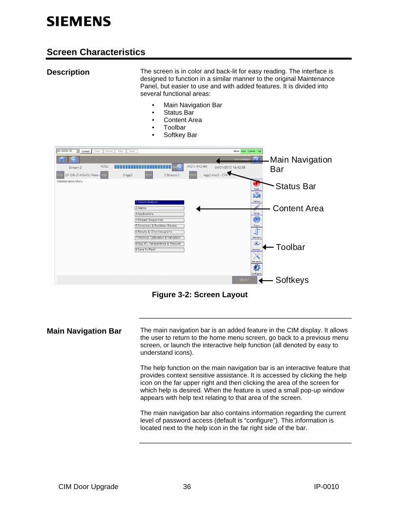
Description The screen is in color and back-lit for easy reading. The interface is designed to function in a similar manner to the original Maintenance Panel, but easier to use and with added features. It is divided into several functional areas:
• Main Navigation Bar • Status Bar • Content Area • Toolbar • Softkey Bar
Main Navigation Bar
Content Area
Softkeys
Toolbar
Status Bar
Figure 3-2: Screen Layout
Main Navigation Bar The main navigation bar is an added feature in the CIM display. It allows the user to return to the home menu screen, go back to a previous menu screen, or launch the interactive help function (all denoted by easy to understand icons).
The help function on the main navigation bar is an interactive feature that provides context sensitive assistance. It is accessed by clicking the help icon on the far upper right and then clicking the area of the screen for which help is desired. When the feature is used a small pop-up window appears with help text relating to that area of the screen.
The main navigation bar also contains information regarding the current level of password access (default is “configure”). This information is located next to the help icon in the far right side of the bar.
CIM Door Upgrade 36 IP-0010

Screen Characteristics, Continued
Status Bar The status bar shows various data about the analyzer, including the name, date and time, and run/hold status. It also shows information about the current application, stream, method, and cycle clock. In addition, the status bar contains gray buttons that permit the user to change the run/hold status or to select the current analyzer, stream, application, and method.
Content Area The middle part of the screen is the general content area. It contains menu lists or parameters with the applicable values, as well as alarm messages and operator hints. The content area is where the primary information for a selected screen is displayed. The top left of the content area is usually a general name or description of the screen.
Toolbar The toolbar is an added feature in the CIM display. It allows the user to navigate directly to commonly used screens. This includes access to the alarm screen as well as settings for valves, temperature, pressure and streams. It also allows the user to easily navigate to the different menu levels (monitor, maintenance, and configure).
The Softkey Bar The softkey bar appears at the lower edge of the screen. Its gray background distinguishes it from the content area. The softkey bar associates different actions with the softkeys located below the screen. The actions vary depending on the screen shown.
No Numerical Keypad The original Maintenance Panel equipped with the Maxum had a numerical keypad that was used for data entry. The CIM display has been designed so that this keypad is not necessary. Menu items can be selected just by tapping the screen. When numerical entry of data is needed, a small pop-up keypad window will be displayed. Elimination of the numerical keypad allows the CIM display to have a much larger readable content area with only a slightly larger panel.
CIM Door Upgrade 37 IP-0010

Using the CIM Display
Navigating the Menus Just like the original Maintenance Panel, the menu tree of the CIM Display is organized into three functional levels. This structure is used to allow different levels of access to analyzer control and configuration operations. The three functional menu levels are as follows.
• Monitor Menu – This menu level allows minimal control of the analyzer and viewing of analyzer status and is intended for operations personnel. All password levels have access to the Monitor Menu; however, higher access is necessary for some functions.
• Maintenance Menu – This menu level allows detailed application and stream control and is intended for engineering personnel. A password with “Maintain” level access is needed to access the Maintenance Menu and all of its functions.
• Configure Menu – This menu level allows system configuration control and is intended for use of system administrators and engineers. A password with “Configure” level access is needed to access the Maintenance Menu. Higher (“Super”) access is needed to access user and password functions.
These different menu levels can be selected using the tool bar icons. The three options show up any time one of the main three menus is displayed. Select the Home icon in the far upper right corner of the CIM Display in order to display the default menu, which will display the menu icons. The toolbar is a new feature created for the CIM display that allows the user to navigate directly to commonly used screens. In addition to selections described above, this includes access to the alarm screen as well as settings for valves, temperature, pressure and streams. To navigate to a screen using the toolbar, simply tap on the desired icon (or click if using the software emulator).
The Toolbar
At the bottom of the screen, below the content area, is the softkey bar. The softkey bar functions just as it did in the original Maintenance Panel. When a menu is displayed, a series of softkeys appears on the softkey bar. As the user navigates through the different screens, the softkeys that appear will depend on the particular screen being displayed.
The Softkey Bar
The function of each softkey is identified by a label on the softkey. You may also see more information about the function of the softkey by using the interactive help feature. Refer to “Accessing Help” later in this section.
To operate a softkey, simply touch it on the display screen (or click on it if using the HMI emulator).
CIM Door Upgrade 38 IP-0010
Using the CIM Display, Continued
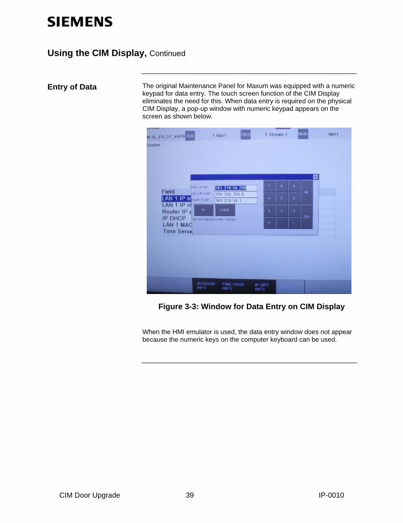
The original Maintenance Panel for Maxum was equipped with a numeric keypad for data entry. The touch screen function of the CIM Display eliminates the need for this. When data entry is required on the physical CIM Display, a pop-up window with numeric keypad appears on the screen as shown below.
Entry of Data
Figure 3-3: Window for Data Entry on CIM Display
When the HMI emulator is used, the data entry window does not appear because the numeric keys on the computer keyboard can be used.
CIM Door Upgrade 39 IP-0010
Using the CIM Display, Continued
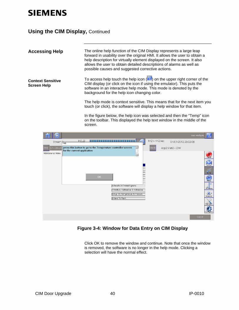
Accessing Help The online help function of the CIM Display represents a large leap forward in usability over the original HMI. It allows the user to obtain a help description for virtually element displayed on the screen. It also allows the user to obtain detailed descriptions of alarms as well as possible causes and suggested corrective actions.
To access help touch the help icon ( ) on the upper right corner of the CIM display (or click on the icon if using the emulator). This puts the software in an interactive help mode. This mode is denoted by the background for the help icon changing color.
Context Sensitive Screen Help
The help mode is context sensitive. This means that for the next item you touch (or click), the software will display a help window for that item.
In the figure below, the help icon was selected and then the “Temp” icon on the toolbar. This displayed the help text window in the middle of the screen.
Figure 3-4: Window for Data Entry on CIM Display
Click OK to remove the window and continue. Note that once the window is removed, the software is no longer in the help mode. Clicking a selection will have the normal effect.
CIM Door Upgrade 40 IP-0010

Using the CIM Display, Continued
One useful feature of the online help function of the CIM display is the ability to get detailed descriptions of alarms as well as possible causes and suggested corrective actions.
Alarm Help
To access alarm help, first load the alarm screen by selecting it from the menu or from the toolbar on the right side of the screen. Next, touch the help icon ( ) on the upper right corner of the CIM display (or click on the icon if using the emulator). This puts the software in the interactive help mode. The background of the help icon will change color when in interactive help mode.
To see help for an alarm, click the “Description” field for that alarm while in interactive help mode. This will display the alarm help screen.
In the figure below, the help icon was selected and then the “Description” field for the first alarm on the list. This displayed the help text window in the middle of the screen.
Figure 3-4: Window for Data Entry on CIM Display
Note that this help box is displayed only when the “Description” field is selected while in help mode. Selecting other fields for the alarm provides help information describing what the field is used for (context sensitive help described on the previous page), rather than information about the alarm.
CIM Door Upgrade 41 IP-0010

Password Restrictions
Description It is possible to configure the CIM Display for different levels of password access. By default, six different levels of password access are available. By default, the display is set for a “configure” level of access, which allows the user to perform almost all analyzer functions except password administration. If the access level of the current active password is not sufficient for a requested operation, a screen will appear stating that the required level of password must be entered. By default, when a password is entered, the session remains active for 30 minutes unless a different time period has been set; see description of “SET TIME” softkey below.
Checking Your Access
To see if you are authorized to perform a specific function, use the appropriate menu path to navigate to that function.
If the following screen appears, then password entry is necessary to perform that function (i.e. the current level of access is not sufficient to perform the function). Select the “LOGIN” softkey and then enter the appropriate password and press OK. If the password is correct and has sufficient access, access level will change (seen in the upper right corner of the display next to the help icon). You are now logged on and can execute the required function. If the password is incorrect, the screen will revert back to the home menu and the access level will not change.
Password Format A password consists of one to six numerical digits and is entered via the numeric keypad.
CIM Door Upgrade 42 IP-0010
CIM Door Upgrade 43 IP-0010
Password Restrictions, Continued
Obtaining/Changing a Password
Passwords can be modified from the User’s Passwords screen on the Configure menu. To change a password you must be logged on with “Super” level access. To change a password, select the table entry for the user and then tap (click) the “SELECT” softkey. This will display a window to modify the password.
Privilege If your password is accepted you can modify any menu items or parameters assigned to your user level (or lower user levels). There are six predefined user levels (levels 0-4 and 99). The items that can be modified at these user levels are predefined and cannot be changed by the user.
By default six users are defined. These are “public”, “operate”, “calibrate”, “maintain”, “configure”, and “super”. The default access level for each of these users matches their names. In addition, multiple individual users may be defined. These users must have unique names and they can be created with either “operate”, “calibrate”, “maintain”, or “configure” access levels. Creation and deletion of users must be performed using the workstation software. (Refer to the System Manager chapter of this manual for instructions on creating and deleting users).
The change privilege remains in effect if the user presses any key before the timeout limit (default 60 minutes). In this manner the user does not have to re-enter a password repeatedly while browsing through menu screens. However, the analyzer automatically logs out (back to the default user), if the user has not pressed a key within the timeout limit.