Embed Size (px)
Citation preview

C576i Self Powered Elliptical Fitness Crosstrainer
Page 21
Procedure 6.1 - Troubleshooting the Lower and Upper Interconnect Cables
Anti-static kits can be ordered from Precor (part number 20024-101).
Troubleshooting the Upper Interconnect Cable
1. Remove the five screws from the rear of the upper display housing. Remove the display housing front panel from the display housing. Disconnect the upper interconnect cable from the upper PCA.
2. Remove the four screws from the access cover below the display. Disconnect the upper interconnect cable from the mid-point connector. Refer to Diagram 6.1
Diagram 6.1 - Data Cable Mid-Point Connector
3. External of the upper column, connect a replacement upper interconnect cable to the mid-point connector and the upper PCA.
4. Check operation as described in Section 4. If the unit works properly, replace the upper interconnect cable as described in Procedure 7.4.
5. If the symptoms are unchanged, remove the external upper interconnect cable. Reconnect the internal upper interconnect cable to the mid-point connector and the upper PCA. Set the display housing front panel in it’s mounting position and fasten it with the five mounting screws removed in step 1. Trouble shoot the lower interconnect cable starting with step 6.
UpperInterconnectCable
Mid-PointConnector
LowerInterconnectCable

C576i Self Powered Elliptical Fitness Crosstrainer
Page 22
Troubleshooting the Lower Interconnect Cable
6. Remove the right side rear cover as described in procedure 7.1.
7. Disconnect the lower interconnect cable from the mid-point connector and the lower PCA. Refer to Diagram 5.1.
8. External of the frame, connect a replacement lower interconnect cable to the mid-point connector and the lower PCA.
9. Check operation as described in Section 4. If the unit works properly, replace the lower interconnect cable as described in Procedure 7.4.
10. If the symptoms are unchanged, remove the external lower interconnect cable. Reconnect the internal lower interconnect cable to the mid-point connector and the lower PCA. Remove the upper and lower interconnect cables from the mid-point connector. Connect a replacement mid-point connector between the two interconnect cables and retest the unit per Procedure 4.
11. If you have performed all of the procedures above and have been unable to correct the problem, call Precor customer support.
C576i Self Powered Elliptical Fitness Crosstrainer
Page 23
Procedure 6.2 - Troubleshooting the Keypad and Upper PCA
If the function keys on the electronic console are unresponsive, the problem may be either the upper PCA or keypad. The keys on this unit are touch sensitive keys. It is necessary to use the keypad diagnostics to troubleshoot the key functions.
WARNINGBefore continuing with this procedure, review the Warning and Caution statements listed in Section One.
1. Attach the anti-static wrist strap to your arm, then connect the ground lead of the wrist strap to the units frame.
2. If the EFX powers up and functions normally until a particular key(s) is pressed, skip to step 12.
3. If a “stuck key” message is immediately displayed when the EFX is powered up, continue with the next step.
4. This condition may be caused by either the keypad or upper PCA.
5. Remove the five screws that fastens the display housing front panel to the display housing backing plate. These screws are located on the rear of the display housing backing plate.
6. Lift the display housing front panel off of the display housing backing plate. Remove the keypad connector from the upper PCA. Refer to Diagram 6.3.
Diagram 6.3 - Upper PCA & Keypad
Upper PCA
KeypadConnector

C576i Self Powered Elliptical Fitness Crosstrainer
Page 24
7. If a “stuck key” message is immediately displayed when the EFX is powered up, replace the upper PCA.
8. If a “stuck key” message is not displayed when the EFX is powered up, replace the display housing front panel. The display housing front panel is equipped with the keypad.
9. If you have performed all of the procedures above and have been unable to correct the problem, call Precor customer service.
10. Access the diagnostics program per procedure 3.2. If the key(s) necessary to access the diagnostic program is not functioning, skip to step 14.
11. Test the keypad per Procedure 3.2.
12. If all of the keys test good, the problem may be user error or a key function that is normally disabled during a particular user program.
13. If one or more keys do not function correctly, either the keypad (display housing) or upper PCA could be defective. Replace the display and repeat step 12. If the display housing did not correct the problem, re-install the original display housing and replace the upper PCA.
14. If you have performed all of the procedures above and have been unable to correct the problem, call Precor customer service.

C576i Self Powered Elliptical Fitness Crosstrainer
Page 25
Procedure 6.3 - Upper Display does not Illuminate
1. Because this is self powered unit, the display will not illuminate until it is used or the optional external power supply is equipped. If the optional external power supply is equipped, the display should be constantly illuminated. If the optional external power supply is not equipped, the unit must be used at a stride rate of 20 strides per minute or higher for the display to illuminate.
2. If the optional external power supply is not equipped, skip to step 5.
3. Disconnect the optional external power supply from the EFX and measure between the inner and outer sleeves of the power supply’s output jack with a DC voltmeter. You should measure approximately 18 VDC.
4. If the voltage measured in step 3 was significantly low, replace the optional external power supply. If the voltage measured in step 3 was 0 Vdc, disconnect external power supply from its AC outlet and measure the voltage at the AC outlet. If the AC outlet voltage is normal replace the optional external power supply. If the AC outlet voltage is significantly low or 0 Vdc, the AC system must be inspected by an electrician.
5. Troubleshoot the generator per Procedure 6.4.
6. If the generator was found to be good, the problem will be in either the lower PCA, upper PCA or the upper to lower PCA interconnect cables.
Warning Because this is a self powered unit, it will either be necessary to either equip the unit with the optional external power supply or have an assistant pedal on the unit while voltage measurements are being taken. Because of the danger of working on the unit while it is in motion using the optional external power supply is strongly recommended.
7. Remove the rear cover and disconnect the interconnect cable from the J2 connector of the lower PCA.
8. The following voltage reading must be taken while the unit is in motion. Extreme care must be taken to keep meter leads, hands, etc. clear of all moving parts. Using a DC voltmeter, measure the voltage between TP13 (+5D) and TP4 (DGND). Refer to Diagram 6.4. The voltage measured should be approximately 5 Vdc. If the voltage is significantly low, replace the lower PCA. Additionally, the DS1 LED should illuminate.
9. Reconnect the interconnect cable to the J2 connector of the lower PCA and repeat the voltage measurement in step 8. The voltage measured should be approximately 5 Vdc. If the voltage is significantly low, the problem is in the upper PCA or the upper to lower PCA interconnect cables.

C576i Self Powered Elliptical Fitness Crosstrainer
Page 26
Diagram 6.4 - Partial View of Lower PCA
10. Troubleshoot the upper to lower PCA interconnect cables per Procedure 6.1.
11. If the upper to lower interconnect cables are found to be good, replace the upper PCA.
12. If you have performed all of the above tests and are unable to resolve the problem, contact Precor customer support.
DGND, TP4
PROM
+5D, TP13
DS1 LED
J2 Connector

C576i Self Powered Elliptical Fitness Crosstrainer
Page 27
Procedure 6.4 - Troubleshooting the Generator
The generator performs three functions in the EFX. First, by controlling the amount of electrical load applied to the generator, the user’s pedalling resistance is controlled. Second, the generator is used to charge the EFX’s internal battery. Lastly, one of the generators six phase output windings is monitored to determine when the unit is in use and when it is idle. This system also determines the stride rate by determining the operating speed (output frequency) of the monitored generator winding.
Warning Because this is a self powered unit, it will either be necessary to either equip the unit with the optional external power supply or have an assistant pedal on the unit while voltage measurements are being taken. Because of the danger of working on the unit while it is in motion using the optional external power supply is strongly recommended.
1. Perform the generator resistance test per Procedure 5.1. If any of the resistance measurements are significantly high or significantly low, replace the generator.
2. The following voltage reading must be taken while the unit is in motion. Extreme care must be taken to keep meter leads, hands, etc. clear of all moving parts. Using an AC voltmeter, measure the voltage between 1 & 3, 2 & 3, 5 & 7 and 6 & 7 on J1 of the lower PCA. All AC voltage readings will vary depending on the unit’s stride rate at the time the measurement is taken. At a stride rate of 100 strides per minute, all three voltage readings will be approximately 100 VAC -110 VAC.
3. If any of the six readings in step 2 are significantly low, replace the generator.
4. If you have performed all of the above tests and are unable to resolve the problem, contact Precor customer support.

C576i Self Powered Elliptical Fitness Crosstrainer
Page 28
Procedure 6.5 - Troubleshooting Hand Held Heart Rate
Circuit DescriptionThe hand held heart rate system is actually a dual system, that is, it can accept a heart rate signal from either the hand held heart rate contacts on the unit’s handlebar or from a Polar heart rate chest strap transmitter. The PCA is configured for hand held priority. That is, if both a chest strap and hand heart rate signal are being received, the system will accept the hand held signal and ignore the chest strap signal. If a hand held signal is not being received, the system will accept the chest strap signal.
Note:There are four typical failure modes for the hand held/chest strap heart rate system. They are: hand held is normal - no chest strap reading; no hand held reading - chest strap normal; no hand held or chest strap reading or constant or intermittent readings when neither hand held or chest strap are in use.
Diagram 6.3 - Hand held/chest strap heart rate PCA
Normal hand held reading - No chest strap reading
1. Access the diagnostic program (Procedure 3.2). Advance to the heart rate display portion of the diagnostic program. Verify that a chest strap signal is not being accepted with either a Polar heart rate test transmitter or a known good chest strap transmitter. If this reading is good, skip to step 3.
2. Using a known good Polar heart rate chest strap, verify that the heart rate operates with the known good chest strap. If the known good Polar chest strap does corrects the problem, replace the original chest strap transmitter.
3. If the above procedures did not correct the problem, replace the heart rate PCA.
5 Vdc
Gnd
Lower Right
Upper Right
Upper LeftLower Left
HR Output
J1
J3
43579-108 or higherHeart Rate PCA

C576i Self Powered Elliptical Fitness Crosstrainer
Page 29
No hand held reading - Normal chest strap reading
4. Access the diagnostic program (Procedure 3.2). Advance to the heart rate display portion of the diagnostic program. Verify that a hand held signal is not being accepted by firmly grasping both the right and left hand held contacts on the handlebars. Cover as much of the contact surface area with your hands as possible (without moving your hands), you should receive a heart rate reading within ten seconds.
5. If the hand held signal is now being accepted, something in the near vicinity is radiating RF (radio frequency) energy that is being received by the chest strap portion of the heart rate PCA.
6. If a hand held signal still not being accepted, skip to step 8.
7. Replace the heart rate PCA with a 43579-108 (or higher) heart rate PCA. 43579-108 and higher versions of heart rate PCA are less susceptible to radiated RF energy.
8. Access the diagnostic program (Procedure 3.2). Advance to the heart rate display portion of the diagnostic program. Verify that a hand held signal is not being accepted by firmly grasping both the right and left hand held contacts with the opposite hands, right hand on the left handlebar contacts and left hand on the right handlebar contacts. Cover as much of the contact surface area with your hands as possible, you should receive a heart rate reading within ten seconds. If a hand held signal is still not being accepted, skip to step 10.
9. If a hand held signal was accepted in step 11, the hand held contact wiring is reversed. The end of the wire harness that connects to the hand held contacts in the handlebar is segregated into two groups. One group has blue shrink wrap around it and the other group has black shrink wrap around it. The “blue” group must go to the right hand contacts and the “black” group must go to the left hand contacts. In both groups the black wire must go to the lower contact and the red wire must go to the upper contact. If necessary, rewire the hand held contacts as described above and test as described in step 4.
10. If the wiring is correct, refer to Diagram 6.3 for the following measurements. With an ohmmeter measure between the “lower right contact” pin on the J1 connector and the lower right hand held heart rate contact on the handlebar. The reading should be 1 � or less. Measure between the “upper right contact” pin on the J1 connector and the upper right hand held heart rate contact on the handlebar. The reading should be 1 � or less. Measure between the “upper left contact” pin on the J1 connector and the upper left hand held heart rate contact on the handlebar. The reading should be 1 � or less. Measure between the “lower left contact” pin on the J1 connector and the lower left hand held heart rate contact on the handlebar. The reading should be 1 � or less. If any of the above readings are greater than 1 �, replace the heart rate PCA to handlebar wire harness.

C576i Self Powered Elliptical Fitness Crosstrainer
Page 30
No hand held reading - No chest strap reading
11. Access the diagnostic program (Procedure 3.2). Advance to the heart rate display portion of the diagnostic program. Verify that neither a chest strap signal or a hand held signal is being accepted with either a heart rate test transmitter or a chest strap transmitter.
12. Check the plug/connector connections on both the heart rate PCA (J4), and upper PCA (J1).
13. If neither a chest strap signal or a hand held signal is being accepted, measure between the “ground” and “5 Vdc” pins on J4 for 5 Vdc. If 5 Vdc is present, replace the heart rate PCA.
14. If 5 Vdc is not present, remove the connector from J4 of the heart rate PCA. Measure between the “ground” and “5 Vdc” pins of the connector (just removed from the heart rate PCA) for 5 Vdc. If 5 Vdc is present, replace the heart rate PCA. If the 5 Vdc is not present, measure between the corresponding pins of J1 on the upper PCA (red and black wires). If 5 Vdc is not present replace the upper PCA. If 5 Vdc is present, replace the upper PCA to heart rate PCA cable.
Constant or intermittent readings when neither the hand held or chest strap is in use
15. Verify that a ferrite core is clamped around the heart rate PCA to upper PCA cable.
16. Constant or intermittent heart rate readings when neither heart rate system is in use is caused by something in the near vicinity radiating RF energy that is being received by the chest strap portion of the heart rate PCA.
17. Replace the heart rate PCA with a 43579-108 (or higher) heart rate PCA. 43579-108 and higher versions of heart rate PCA are less susceptible to radiated RF energy

C576i Self Powered Elliptical Fitness Crosstrainer
Page 31
Procedure 6.6 - Troubleshooting the Incline System
The incline motor is a 12 Vdc motor with an internally driven 1 K� potentiometer used to track ramp position. Because the incline motor is a DC motor, incline motor direction is controlled by the polarity of the DC voltage applied to the incline motor. When a positive voltage is applied to the incline motor, the incline motor will move upward. When a negative voltage is applied to the incline motor, the incline motor will move downward. As the incline motor moves the 1 K�potentiometer is rotated via an internal gear drive system. The potentiometer’s changing resistance is fed to the incline control system and converted to and A/D (analog to digital) reading that is used in the diagnostics system to indicate ramp position. The ramp operating system has a battery monitoring system. If the battery voltage falls below 11 Vdc when ramp movement is initiated or the battery voltage falls below 10 Vdc after ramp movement has been initiated, ramp movement will be stopped and the message “NO RAMP LOW VOLTAGE” will be displayed. Ramp motion will not be enabled until such time as the battery voltage exceeds the above limits. The battery voltage must be raised to correct this condition either by battery charging or battery replacement. This is strictly a battery problem and not a incline system or incline motor problem.
1. If an Error 40 (no incline movement) is being displayed continue with step 2. If an Error 42 is being displayed (incline out of range) skip to step 12.
2. If the incline moves briefly and then displays an Error 40, skip to step 12. If the incline does not move prior to displaying the Error 40 continue with step 3.
3. Remove the rear cover. Remove the F1 fuse (6.3 amps) from the lower PCA. See Diagram 6.4. Check the fuses resistance using an ohmmeter. The fuse should read 1 � or less. If the reading is significantly high, replace the fuse. If the fuse is good or replacing the fuse does not correct the problem, continue with step 4.
4. Enter the diagnostic program per Procedure 3.2. Using the diagnostic program allows you to test the incline system without continuously pedalling the unit. Connect a DC volt meter to the J3 connector on the lower PCA as follows: voltmeter common lead to terminal 3 (black wire) and voltmeter “hot” lead to terminal 2 (red wire). Using the CROSSRAMP �,� keys operate the incline. The voltmeter should read +12 Vdc when the incline is instructed to move upward and -12 Vdc when the incline is instructed to move downward.
5. If when the CROSSRAMP keys are pressed, the display does not indicate that the incline should be moving, troubleshoot the upper PCA and keypad per Procedure 6.2.
6. If the voltage measurements in step 4 are correct continue with step 7. If the either voltage measurement in step 4 is significantly low, replace the lower PCA.
7. Verify that all of the wires in the intermediate cable (the cable inserted in to J3 of the lower PCA) are securely inserted into the connector housing and providing a good electrical connection.

C576i Self Powered Elliptical Fitness Crosstrainer
Page 32
8. Remove the lift cover per Procedure 7.2. Enter the diagnostic program, if necessary, per Procedure 3.2. Using the diagnostic program allows to test the incline system without continuously pedalling the unit. Connect a DC volt meter to the incline motor cable as follows: voltmeter common lead to terminal 2 (brown wire) and voltmeter “hot” lead to terminal 3 (red wire). Using the CROSSRAMP �,� keys operate the incline. The voltmeter should read +12 Vdc when the incline is instructed to move upward and -12 Vdc when the incline is instructed to move downward.
9. If the voltage measurements in step 8 are correct replace the incline motor. If the either voltage measurement in step 4 is significantly low, continue with step 10.
10. Verify that all of the wires in the intermediate cable (the cable inserted in to J3 of the lower PCA) are securely inserted into the connector housing and providing a good electrical connection.
11. If you have performed all of the above tests and are unable to resolve the problem, contact Precor customer support
12. Enter the diagnostic program per Procedure 3.2 and advance to the Lift Test. If the A/D reading is either 0 or 255, skip to step 15.
13. Using the CROSSRAMP �,� keys operate the incline. If the A/D reading tracks the incline movement smoothly without skips, calibrate the incline motor per Procedure 5.3 and re-test incline functions in a normal operating mode.
14. If the A/D reading was erratic and did not smoothly follow incline motion, visually check the connections between the intermediate cable and the J3 connector on the lower PCA and between the intermediate cable.
15. Exit the diagnostics program, and leave the unit idle long enough for it to “shut off”. Disconnect the red battery lead from terminal M6 of the lower PCA. Remove the intermediate cable from the J3 connector of the lower PCA. Using an ohmmeter, test between terminal 4 (green wire) and terminal 6 (brown wire) of the intermediate cable. The ohmmeter should read approximately 1000�.
16. Test between terminal 4 (green wire) and terminal 5 (black wire) of the intermediate cable and between terminal 5 (black wire) and terminal 6 (brown wire) of the intermediate cable. These two readings should total approximately 1000�.
17. If the readings in steps 15 and 16 are correct, skip to step 19. If either reading is significantly high or low, continue with step 18.
18. Disconnect the intermediate cable from the incline motor cable. Using an ohmmeter read each of the six wires in the intermediate cable from end to end. Each of the wires in the intermediate cable should read less than 1�� If any of the readings are significantly high, replace the intermediate cable. If all of the readings are correct, continue with step 19.
19. Replace the incline motor. Calibrate the incline motor per Procedure 5.3.

C576i Self Powered Elliptical Fitness Crosstrainer
Page 33
Procedure 7.1 - Replacing the Rear Covers
WARNINGBefore continuing with this procedure, review the Warning and Caution statements listed in Section One, Things You Should Know.
Replacing the Left and/or Right Side Rear Cover
1. Remove the two screws at the rear of the rear cover.
2. Grasp the left side cover and rotate it clockwise to remove it.
3. Grasp the right side cover rotate it counterclockwise to remove it.
4. Reverse steps 2 and three to replace the left and ride side covers. Replace the screws removed in step 1 to fasten the left and right side covers.
Replacing the Top Section of the Rear Cover
5. Remove the left and right side covers as described above.
6. Loosen, do not remove, the two screws that fasten the top cover to the frame upright.
7. Remove the two screws the fasten the top cover to the front cover and remove the top cover.
8. Set the replacement top cover in its mounting position and fasten it with the four screws removed in steps 2 and 3.
9. Replace the left and right side covers as described above.
Replacing the Rear Section of the Rear Cover
10. Remove the left and right side covers as described above.
Diagram 7.1 - External Power Supply Input Jack
External PowerSupplyInput jack

C576i Self Powered Elliptical Fitness Crosstrainer
Page 34
11. Remove the top section of the cover as described above.
12. Remove the nut retaining the external power supply input jack. Refer to Diagram 7.1
13. Remove the external power supply input jack from the cover.
14. Remove the four screws (2 each side) that fasten the cover to the frame. Slide the two wire clips off of the cover’s left side. Remove the cover from the EFX.
15. Set the replacement cover in its mounting position and fasten it with the screws removed in step 12. Slide the two wire clips into place on the covers left side.
16. Set the external power supply input jack at its mounting location and fasten it with the nut removed in step 10.
17. Replace the left and right side covers as described above.
Replacing the Front Section of the Rear Cover
18. Remove the left and right side covers as described above.
19. Remove the top section of the cover as described above.
20. Remove the four screws that fasten the rear cover section to the frame. Carefully slide the rear cover section rearwards a couple of inches. to clear the overlap between the front and rear cover sections.
21. Remove the cables from the two lower cable clips on the inside of the front section of the cover.
22. Remove the two screws that fasten the lower PCA mounting bracket to the front section of the cover. Refer to Diagram 7.2.
Diagram 7.2 - Lower PCA Mounting Bracket
MountingScrew
MountingBracket

C576i Self Powered Elliptical Fitness Crosstrainer
Page 35
23. Remove the lower PCA and bracket and carefully support it away from the front section of the cover.
24. Remove the small cover at the front portion of the cover section by sliding it forward and off of the front section of the cover. Refer to Diagram 7.3. Remove the two cover mounting screws.
Diagram 7.3 - Small Cover
25. Remove the front section of the cover from the EFX. Remove the cable clips from the cover and snap them into their mounting positions in the replacement cover.
26. Set the replacement cover in its mounting position. Fasten the cover with the two screws removed in step 25. Slide the small cover, removed in step 24, onto the front section of the cover.
27. Slide the rear section of the cover back into its mounting position and fasten it with the four screws removed in step 20.
28. Set the lower PCA and mounting bracket in its mounting position and fasten it with the two screws removed in step 22.
29. Dress the cables, remove in step 21, into the two lower cable clips on the front section of the cover.
30. Replace the top section of the cover as described above.
31. Replace the left and right cover sides as described above.
Small Cover Cover Mounting Screws

C576i Self Powered Elliptical Fitness Crosstrainer
Page 36
Procedure 7.2 - Replacing the Lift Covers
Replacing the Upper Lift Cover Section
1. The large upper section of the front cover is fastened to the lower cover sections. However, there are two plastic clips, one on each side of the upper lift cover, that retain the upper portion of the lift cover to the uprights. To remove the upper lift cover section, lower the incline to its lowest position, to provide clearance.
2. The plastic cover clips must be carefully levered out of their mountings. Insert a narrow flat bladed screw driver in the slot in the front of the cover clip. See Diagram 7.4.
Diagram 7.4 - Lift Cover Clip
3. Carefully pry the cover clip away from the pivot cover. There are latching tabs in the front and rear of the cover clip. All of the latching tabs must disengage from the pivot cover in order to remove the cover clip.
4. Lift the upper lift cover section off of the lower cover sections.
5. Set the replacement upper lift cover section on in its mounting position on the lower cover sections.
6. Replace the cover clips by setting them in their mounting position and pressing them into place. Press the rear portion of the clip into place first then the front portion of the cover clip.
Cover Clip
Slot
Lift Cover
Pivot Cover

C576i Self Powered Elliptical Fitness Crosstrainer
Page 37
Replacing the Lower Front Lift Cover Section
7. Remove the upper lift cover section as described above.
8. Remove the four screws that fasten the front cover section to the rear cover section. Remove the front cover section from the EFX.
9. Set the replacement front cover section in its mounting position and fasten it with the four screws removed in step 4.
Replacing the Lower Rear Lift Cover Section
10. Remove the upper and front cover sections as described above.
11. Remove the hitch pin from the clevis at the lower mount of the incline motor. Remove the clevis pin from the lower incline motor mount. Lift the incline motor out of its mounting position and set it on the floor in front of the EFX. Refer to Diagram 754.
12. Remove the two screws that fasten the battery bracket to the rear cover section and remove the battery bracket.
13. Slide the battery out of the rear cover section and set it on the floor beside the incline motor.
14. Remove the two screws that fasten the rear cover section to the frame. Remove the rear cover section from the EFX.
15. Set the replacement rear cover section in its mounting position and fasten it with the screws removed in step 10.
16. Set the battery in its mounting position. Set the battery bracket in its mounting position and fasten it with the screws removed in step 8.
Diagram 7.5 - Rear Cover SectionRear CoverSection
InclineMotor
MountingScrews
Battery

C576i Self Powered Elliptical Fitness Crosstrainer
Page 38
17. Set the incline motor in its mounting position and slide the clevis pin into the incline motor’s lower mount. Fasten the clevis pin with the hitch pin.
18. Replace the front and upper cover sections as described above.

C576i Self Powered Elliptical Fitness Crosstrainer
Page 39
Procedure 7.3 - Replacing the Display Enclosure or Upper PCA
Anti-static kits (part number 20024-101) can be ordered from Precor.
The keyboard is part of the display housing front panel. If the keyboard is not functioning properly, replace the display housing front panel.
Removing the Display Housing Front Panel
1. Remove the rear cover and disconnect the red battery lead from terminal M6 of the lower PCA.
WARNINGBefore continuing with this procedure, review the Warning and Caution statements listed in Section One, Things You Should Know.
2. Attach the anti-static wrist strap to your arm, then connect the ground lead of the wrist strap to the units frame.
3. Remove the four screws that secure the display housing front panel to the display backing plate.
4. Attach the wrist strap to your arm, then connect the ground lead of the wrist strap to the EFX frame.
5. Disconnect the upper interconnect cable from the upper PCA (connector J5).
Removing and Replacing the Upper PCA
6. Carefully disconnect the keyboard cable from the upper PCA (connector J2).
7. Remove the four screws that secure the upper PCA to the display housing front panel.
Note:Package the upper PCA in an anti-static bag and document the problem as described in Procedure 3.6, Documenting Software Problems.

C576i Self Powered Elliptical Fitness Crosstrainer
Page 40
Diagram 7.6 - Display Housing Front Panel, Rear View
8. Position the upper PCA at its mounting location on the display housing front panel (refer to Diagram 7.6). Replace and tighten the upper PCA mounting screws.
9. Reconnect the keyboard cable to the upper PCA.
10. Reconnect the upper interconnect cable to the upper PCA.
11. Remove the ground lead of the wrist strap from the EFX frame, then remove the wrist strap from your arm.
12. Position the display enclosure on the display plate. Replace and tighten the display mounting screws.
13. Replace the red battery lead removed in step 1 and check unit operation as described in Section Four.
Upper PCA
KeypadCable
J5Connector

C576i Self Powered Elliptical Fitness Crosstrainer
Page 41
Procedure 7.4 - Replacing the Lower PCA
Removing the Lower PCA
1. Remove the rear cover and disconnect the red battery lead from terminal M6 of the lower PCA.
WARNINGBefore continuing with this procedure, review the Warning and Caution statements listed in Section One, Things You Should Know.
2. Remove the right side rear cover per Procedure 7.1.
3. Attach the wrist strap to your arm, then connect the ground lead of the wrist strap to the EFX frame.
4. Disconnect the all of cables and wiring from the lower PCA.
5. Remove the four screws that secure the lower PCA to its mounting bracket, refer to Diagram 7.7.
Diagram 7.7 - Lower PCA
Replacing the Lower PCA
6. Position the replacement lower PCA at its mounting position and fasten the lower PCA with the four screws removed in step 5.
MountingScrew
LowerPCA
InterconnectCable

C576i Self Powered Elliptical Fitness Crosstrainer
Page 42
7. Reconnect the lower PCA cables and wiring as follows. Connect the interconnect cable to connector J2. The 2 conductor cable (red and black wires) from the input power jack to the J4 connector. The 6 conductor cable from the generator to connector J1.The 6 conductor cable from the incline motor to connector J5. From the battery, connect the red wire to M6 and the black wire to M7 of the lower PCA. Connect the two leads from the load resistors to M1 and M2, the polarity of the load leads is not critical, either lead may be connected to either the M1 or M2 terminal.
8. Remove the ground lead of the wrist strap from the EFX frame, then remove the wrist strap from your arm.
9. Re-install the rear cover, then check the operation of the C576i as described in Section Four.

C576i Self Powered Elliptical Fitness Crosstrainer
Page 43
Procedure 7.5 - Replacing the Upper or Lower Interconnect Cables
Before you install a new interconnect cable, ensure that the interconnect cable is defective as described in Procedure 6.1.
WARNINGBefore continuing with this procedure, review the Warning and Caution statements listed in Section One, Things You Should Know.
1. Attach the wrist strap to your arm, then connect the ground lead of the wrist strap to the EFX frame.
Replacing the Upper Interconnect Cable
2. Remove the display housing per Procedure 7.3.
3. The upper and lower interconnect cables are connected behind the access cover below the the display. Refer to Diagram 6.1.
4. Disconnect the upper interconnect cable from the mid-point connector. Tape the end of the replacement interconnect cable with the to the upper end of the old interconnect cable (display housing end).
5. Carefully pull the old interconnect cable out of the mid-point access hole while feeding the new interconnect cable into the unit. When the new cable is fully into the unit, remove the tape and discard the old interconnect cable. Connect the upper interconnect cable to the mid-point connector and push them into the access hole.
6. Connect the upper interconnect cable to the upper PCA. Replace the display housing per Procedure 7.3.
7. Remove the ground lead of the wrist strap from the EFX frame, then remove the wrist strap from your arm.
8. Check the operation of the EFX as described in Section Four.
Replacing the Lower Interconnect Cable
9. Remove the right side rear cover per Procedure 7.1. Disconnect the interconnect cable from the lower PCA (connector J2). Refer to Diagram 7.7.
10. The upper and lower interconnect cables are connected behind the access cover below the the display. Refer to Diagram 6.1.
11. Disconnect the lower interconnect cable from the mid-point connector. Tape the replacement interconnect cable to the old interconnect cable at the lower PCA end of the old interconnect cable.

C576i Self Powered Elliptical Fitness Crosstrainer
Page 44
12. Carefully pull the old interconnect cable out of the mid-point access hole while feeding the new interconnect cable into the unit. When the new cable is fully into the unit, remove the tape and discard the old interconnect cable. Connect the lower interconnect cable to the mid-point connector and push them into the access hole.
13. Connect the new interconnect cable to the lower PCA.
14. Check the operation of the EFX as described in Section Four.

C576i Self Powered Elliptical Fitness Crosstrainer
Page 45
Procedure 7.6 - Replacing a Crankarm Assembly
Removing a Crankarm Assembly
WARNINGBefore continuing with this procedure, review the Warning and Caution statements listed in Section One, Things You Should Know.
1. It is only necessary to remove the right or left side of the rear cover to access the crankarm being replaced. Remove the necessary side(s) of the rear cover.
2. Remove the stairarm assembly as described in Procedure 7.14.
Note:Notice the position of the two crank arms. When the crankarms are replaced, they must be positioned so that they are 180 degrees opposing.
3. Remove the axle bolt that secures the crankarm to the input pulley shaft. Remove the pinch bolt. Refer to Diagram 7.8. It may be necessary, use a Pitman arm puller or 4” to 6 “gear puller to remove the crankarm. Do not use a hammer or mallet to remove the crankarm.
4. If you are removing both crank arm assemblies, repeat steps 2 and 3 for the second crankarm assembly.
Diagram 7.8 - Crankarm
Pinch Bolt
Axle Bolt
Retaining Ring

C576i Self Powered Elliptical Fitness Crosstrainer
Page 46
Replacing a Crank Arm Assembly
5. Clean the crankarm mounting bolt threads and the input pulley shaft threads with an alcohol swab. Allow them to dry and apply blue loctite to the crankarm mounting bolt threads.
6. Position the crankarm on the input pulley shaft. Thread and hand tighten the axle bolt into the input pulley shaft. Torque the axle bolt to 200 in/lbs.
7. Replace the pinch bolt and locknut, torque the pinch bolt to 400 inch pounds.
8. Replace the stairarm assembly as described in Procedure 7.12, steps 11 to 12.
9. If you are replacing both crankarm assemblies, repeat steps 6 and 7 for the second crankarm assembly.
10. Replace the right side and/or left side rear cover.

C576i Self Powered Elliptical Fitness Crosstrainer
Page 47
Procedure 7.7 - Replacing a Incline Motor
1. Remove upper and front cover sections per Procedure 7.1.
2. Remove the hitch pin from the clevis at the lower incline motor mount. Remove the clevis pin from the lower incline motor mount.
3. Carefully lift the incline motor out of its mount and set it on the floor in front of the EFX, Refer to Diagram 7.9.
Diagram 7.9 - Incline Motor
4. Disconnect the intermediate cable from the incline motor cable.
5. Remove the two bolts that fasten the incline motor yoke into the ramp. Refer to Diagram 7.16.
6. Carefully, slide the incline motor yoke out of the ramp and lower the ramp until it is resting on the frame.
7. Thread the incline yoke assembly off of the incline motor’s drive screw.
8. Thread the incline yoke assembly, removed in step 7, onto the replacement incline motor’s drive screw.
Incline MotorIntermediate Cable
Hitch PinClevis Pin

C576i Self Powered Elliptical Fitness Crosstrainer
Page 48
9. Connect the replacement incline motor’s cable to the intermediate cable.
10. Mount the incline motor to the EFX frame with the clevis and hitch pins removed in step 2.
11. Calibrate the incline motor per Procedure 5.3.
12. Replace front and upper cover sections per Procedure 7.1.
13. Check the operation of the EFX as described in Section Four.

C576i Self Powered Elliptical Fitness Crosstrainer
Page 49
Procedure 7.8 - Replacing the Input Pulley Belt
WARNINGBefore continuing with this procedure, review the Warning and Caution statements listed in Section One, Things You Should Know.
1. Remove the left and right side rear covers per Procedure 7.1.
2. Remove the stairarm assemblies as described in Procedure 7.14
3. Remove the crankarm assemblies as described in Procedure 7.7.
4. Remove the input pulley assembly per Procedure 7.10.
5. Remove the left and right tension bolts, locking tabs and brackets from the step up pulley assembly. Remove the generator belt from the generator’s pulley.
6. Slide the step up pulley assembly with both the generator and input pulley belts out of the drive unit.
7. Remove the input pulley belt. Set the replacement input pulley belt in it’s mounting position on the step up pulley assembly.
8. Set the step up pulley assembly with the generator and input belt at its mounting position in the drive unit. Replace the tensioning bolts, locking tabs and brackets removed in step 6. Thread, but do not tighten, the left and right tension bolts into the step up pulley shaft.
9. Place the other end of the generator belt on the generator’s pulley.
10. Place the other end of the input pulley belt on the input pulley assembly and mount the input assembly per Procedure 7.10
11. Replace the crankarm assemblies per Procedure 7.7.
12. Replace the stairarm assemblies per Procedure 7.14
13. Tension both belts per Procedure 5.2. Note the differences between tensioning a new belt and a existing (used) belt.
14. Check the operation of the EFX as described in Section Four.

C576i Self Powered Elliptical Fitness Crosstrainer
Page 50
Procedure 7.9 - Replacing the Generator Pulley Belt
WARNINGBefore continuing with this procedure, review the Warning and Caution statements listed in Section One, Things You Should Know.
1. Remove the left and right side rear covers per Procedure 7.1.
2. Remove the stairarm assemblies as described in Procedure 7.14
3. Remove the crankarm assemblies as described in Procedure 7.7.
4. Remove the input pulley assembly per Procedure 7.10
5. Remove the left and right tension bolts, locking tabs and brackets from the step up pulley assembly.
6. Remove the three generator mounting screws shown in Diagram 7.19.
7. Remove the two bearing clamp screws shown in Diagram 7.20. Remove the bearing clamp.
8. Lift the generator and remove its drive belt.
9. Slide the step up pulley assembly with both the generator and input belts out of the drive unit.
10. Remove the generator belt. Set the replacement generator belt in it’s mounting position on the step up pulley assembly.
11. Set the step up pulley assembly with the generator and input belt at its mounting position in the drive unit. Replace the tensioning bolts, locking tabs and brackets removed in step 6. Thread, but do not tighten, the left and right tension bolts into the step up pulley shaft.
12. Lift the generator and place the drive belt around the generator’s pulley.
13. Replace and tighten the three generator mounting screws removed in step 6. Set the bearing clamp in its mounting position, replace and tighten the two bearing clamp mounting screws removed in step 7.
14. Mount the input assembly per Procedure 7.14.
15. Replace the crankarm assemblies per Procedure 7.7.
16. Replace the stairarm assemblies per Procedure 7.10.
17. Tension both belts per Procedure 5.2. Note the differences between tensioning a new belt and a existing (used) belt.

C576i Self Powered Elliptical Fitness Crosstrainer
Page 51
18. Check the operation of the EFX as described in Section Four.

C576i Self Powered Elliptical Fitness Crosstrainer
Page 52
Procedure 7.10 - Replacing the Input Pulley Assembly
WARNINGBefore continuing with this procedure, review the Warning and Caution statements listed in Section One, Things You Should Know.
1. Remove the left and right side rear covers per Procedure 7.1.
2. Remove the stairarm assemblies as described in Procedure 7.14.
3. Remove the crankarm assemblies as described in Procedure 7.7
4. Remove the input pulley assembly mounting nuts (2 per pillow block bearing).
5. Straighten the locking tabs and turn the left and right tension bolts counterclockwise until tension is removed from the both belts. (Refer to Diagram 5.2)
Diagram 7.10 - Input Pulley Assembly
6. Remove the input pulley assembly. Slide input pulley belt off of the input pulley assembly.
7. Hold the replacement input pulley assembly at it’s mounting position and slide the input belt over and past the pillow block bearing and onto the input pulley assembly.
8. Replace the nuts on the pillow block bearings and torque them to 400 inch pounds.
PillowBlock
Bearing
InputPulleyAssembly
Crankarm

C576i Self Powered Elliptical Fitness Crosstrainer
Page 53
9. Replace the crankarms per Procedure 7.7. The crankarms must be parallel to the frame uprights. Refer to Diagram 7.10. If necessary loosen the four drive unit mounting bolts, align the drive unit and torque the drive unit mounting bolts to 400 inch pounds.
10. Tension both belts per Procedure 5.2. Note the differences between tensioning a new belt and a existing (used) belt.
11. Replace the left and right side rear covers.

C576i Self Powered Elliptical Fitness Crosstrainer
Page 54
Procedure 7.11 - Replacing the Step-Up Pulley Assembly
WARNINGBefore continuing with this procedure, review the Warning and Caution statements listed in Section One, Things You Should Know.
1. Remove the left and right side rear covers per Procedure 7.1.
2. Remove the stairarm assemblies as described in Procedure 7.14.
3. Remove the crankarm assemblies as described in Procedure 7.7.
4. Remove tension from the input pulley and generator belts as described below:
a. Straighten the locking tabs and turn the left and right tension bolts counterclockwise untiltension is removed from the both belts. (Refer to Diagram 5.2)
b. Remove both tension bolts and slide the input belt off of the step up pulley assembly.
5. Place the input belt and step up belt in place on the replacement step up pulley. Set other end of the generator belt on the generator pulley.
6. Replace the tension bolts and associated hardware removed in step 4b.
7. Tension both belts per Procedure 5.2. Note the differences between tensioning a new belt and a existing (used) belt.
8. Replace the crankarms per Procedure 7.7.
9. Replace the left and right side rear covers.

C576i Self Powered Elliptical Fitness Crosstrainer
Page 55
Procedure 7.12 - Replacing a Stairarm Wheel
Procedure
WARNINGBefore continuing with this procedure, review the Warning and Caution statements listed in Section One, Things You Should Know.
1. Remove the lift cover per Procedure 7.2.
2. Grasp the center ramp cover and lift it upwards to unsnap it from the ramp. Remove the center ramp cover from the EFX and set it aside.
3. Remove the two screws that fasten the ramp end cap to the ramp. Remove the ramp end cap. Refer to Diagram 7.11.
Diagram 7.11 -Ramp Assembly
4. The left side and/or right side ramp trim will need to be removed in order to access the stairarm wheels.
5. Loosen, but do not remove, the five screws that fasten ramp trim(s) required to access the wheel(s) being replaced. Slide the ramp trim(s) off the front of the ramp.
6. Remove the screw retaining the wheel being replaced. Refer to Diagram 7.12. Slide the wheel off the stairarm axle.
Left SideRamp Trim
Right SideRamp Trim
End CapRamp
Center RampCover

C576i Self Powered Elliptical Fitness Crosstrainer
Page 56
Diagram 7.12 - Stairarm Wheel
7. Slide the replacement wheel onto the stairarm axle. Fasten the wheel with the hardware removed in step 6. Apply blue loctite to the wheel mounting screws and torque them to 180 inch pounds.
8. Repeat the procedure in steps 6 and 7 for each wheel being replaced.
9. Align the T-nuts on the ramp trim(s) with the channel in the bottom front of the ramp. Slide the trim onto the ramp while feeding each T-nut into the ramp channel. Do not tighten the trim fastening screws at this time. Repeat this procedure with the remaining trim strip, if required.
10. Set the ramp end cap at its mounting position and fasten it with the screws removed in step 3.
11. Align the ramp trim(s) with the ramp end cap and tighten the five trim mounting screws.
12. Set the ramp center cover at its mounting position and press downward to snap it onto place.
13. Replace the lift cover per Procedure 7.2.
StairarmWheel
MountingScrew

C576i Self Powered Elliptical Fitness Crosstrainer
Page 57
Procedure 7.13 - Replacing a Stairarm Pedal
1. Loosen and remove the four screws that fasten the stairarm pedal onto the stairarm. Refer to Diagram 7.13.
2. Remove the stairarm pedal from the stairarm.
3. Set the replacement stairarm pedal at it’s mounting position on the stairarm.
4. Install and tighten the stairarm pedal mounting hardware removed in step 2.
Diagram 7.13 - Stairarm Pedal
PlasticSpacer
MountingScrew
PedalStairarm

C576i Self Powered Elliptical Fitness Crosstrainer
Page 58
Procedure 7.14 - Replacing a Stairarm
1. Remove the left and right side rear cover.
2. Remove the cover from the rear of the stairarm. The cover’s retaining screw is on the inside and must be accessed from the opposite side of the EFX. Carefully, rotate the stairarm to a position just forward of vertical to gain access to the cover’s retaining screw.
3. Remove the lift cover per Procedure 7.2.
4. Grasp the center ramp cover and lift it upwards to unsnap it from the ramp. Remove the center ramp cover from the EFX and set it aside.
5. Remove the two screws that fasten the ramp end cap to the ramp. Remove the ramp end cap. Refer to Diagram 7.11.
6. The left side and/or right side ramp trim will need to be removed in order to access the stairarm wheels.
7. Loosen, but do not remove, the five screws that fasten ramp trim(s) required to access the wheel(s) being replaced. Slide the ramp trim(s) off the front of the ramp.
8. Remove the plastic cap from the stairarm connector. Remove the bolt that fastens the stairarm connector to the stairarm. Retain the bolt, two washers, a steel spacer and a large black spacer for later use. Refer to Diagram 7.14.
Diagram 7.14 - Stairarm and Stairarm Connector
MountingBolt
StairarmConnector
PlasticCap
RetainingRing Stairarm

C576i Self Powered Elliptical Fitness Crosstrainer
Page 59
9. Remove the retaining ring that fastens the stairarm to the crankarm and remove the stairarm from the EFX.
10. Remove the stairarm pedal per Procedure 7.13 and install it on the replacement stairarm. Refer to Procedure 7.13.
11. Remove both wheels and slide them onto the replacement stairarm’s axle. Apply blue loctite to the wheel mounting screws and torque the wheel mounting screws to 180 inch pounds.
12. Slide the stairarm onto the crankarm and set the stairarm in its ramp track. Fasten the stairarm to the crankarm with the retaining ring removed in step 7.
13. Slide the large black spacer onto its mounting position on the replacement stairarm. Slide the steel spacer into the end of the stairarm connector. Fasten the stairarm connector to the stairarm with the bolt, removed in step 6, and a washer on each side of the steel spacer in the end of the stairarm connector.
14. Align the T-nuts on the ramp trim(s) with the channel in the bottom front of the ramp. Slide the trim onto the ramp while feeding each T-nut into the ramp channel. Do not tighten the trim fastening screws at this time. Repeat this procedure with the remaining trim strip, if required.
15. Set the ramp end cap at its mounting position and fasten it with the screws removed in step 3.
16. Align the ramp trim(s) with the ramp end cap and tighten the five trim mounting screws.
17. Set the ramp center cover at its mounting position and press downward to snap it onto place.
18. Replace the lift cover per Procedure 7.2.
19. Replace the stairarm cover(s) with the hardware removed in step 2.
20. Replace the left and right side covers per Procedure 1.
C576i Self Powered Elliptical Fitness Crosstrainer
Page 60
Procedure 7.15 - Replacing a Ramp Assembly
Procedure
1. Raise the incline to its highest position.
2. Remove both stairarms per Procedure 7.14.
3. Remove the four bolts that fasten the ramp pivot to the ramp. Refer to Diagram 7.15.
Diagram 7.15 - Rear Ramp Mounting
4. Remove the two bolts that fasten the incline yoke into the ramp. Refer to Diagram 7.16. Carefully, slide the incline out of the ramp and lower the ramp to the frame. Take care to not allow the incline yoke to rotate on the incline motor’s drive screw. If the yoke can not be returned to the same position it was in before the incline yoke was removed, an incline calibration (Procedure 5.3) must be performed before the incline motor is reinstalled in the ramp.
Diagram 7.16 - Front Ramp Mounting
RampPivotMounting
Bolt
Incline Yoke
Incline YokeMounting Bolts

C576i Self Powered Elliptical Fitness Crosstrainer
Page 61
5. Remove the ramp from the EFX.
6. Remove the two screws that fasten the rear ramp end cap to the ramp. Set the rear ramp end cap at its mounting position on the replacement ramp and fasten with the screws removed above.
7. Set the replacement ramp in its mounting position and hand start ramp pivot mounting bolts removed in step 3. Do not tighten them at this time.
8. Slide incline yoke into its mounting position in the ramp and fasten it with the hardware removed in step 4.
9. Apply blue loctite to the four ramp pivot bolts (hand started in step 7) and torque them to 480 inch pounds (40 foot pounds).
10. Slide the stairarm onto the crankarm and set the stairarm in its ramp track. Fasten the stairarm to the crankarm with the retaining ring removed in step 7.
11. Slide the large black spacer onto its mounting position on the stairarm. Slide the steel spacer into the end of the stairarm connector. Fasten the stairarm connector to the stairarm with the bolt, removed in step above, and a washer on each side of the steel spacer in the end of the stairarm connector.
12. Align the T-nuts on the ramp trim(s) with the channel in the bottom front of the ramp. Slide the trim onto the ramp while feeding each T-nut into the ramp channel. Do not tighten the trim fastening screws at this time. Repeat this procedure with the remaining trim strip, if required.
13. Set the ramp end cap at its mounting position and fasten it with the screws removed in step 3.
14. Align the ramp trim(s) with the ramp end cap and tighten the five trim mounting screws.
15. Set the ramp center cover at its mounting position and press downward to snap it onto place.
16. Replace the lift cove per Procedure 7.2.
C576i Self Powered Elliptical Fitness Crosstrainer
Page 62
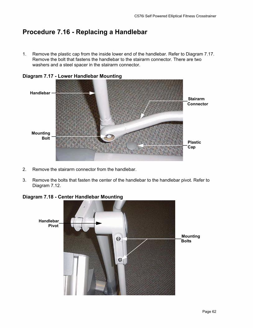
Procedure 7.16 - Replacing a Handlebar
1. Remove the plastic cap from the inside lower end of the handlebar. Refer to Diagram 7.17. Remove the bolt that fastens the handlebar to the stairarm connector. There are two washers and a steel spacer in the stairarm connector.
Diagram 7.17 - Lower Handlebar Mounting
2. Remove the stairarm connector from the handlebar.
3. Remove the bolts that fasten the center of the handlebar to the handlebar pivot. Refer to Diagram 7.12.
Diagram 7.18 - Center Handlebar Mounting
StairarmConnector
PlasticCap
Handlebar
MountingBolt
MountingBolts
HandlebarPivot

C576i Self Powered Elliptical Fitness Crosstrainer
Page 63
4. Set the handlebar at its mounting position and hand start the mounting bolts removed in step 3 that fasten the handlebar to the handlebar pivot. Do not tighten them at this time.
5. Slide the spacer into the stairarm connector and place a washer on each side of the spacer. Position the handlebar and the stairarm connector at their mounting positions and hand start the mounting bolt.
6. Securely tighten the handlebar to stairarm connector bolt. Replace the plastic cap on the stairarm connector.
7. Torque the handlebar to handlebar pivot bolts to 150 inch pounds.

C576i Self Powered Elliptical Fitness Crosstrainer
Page 64
Procedure 7.17 - Replacing a Stairarm Connector
WARNINGBefore continuing with this procedure, review the Warning and Caution statements listed in Section One, Things You Should Know.
1. Remove the plastic cap from the stairarm end of the stairarm connector. Remove the bolt that fastens the stairarm connector to the stairarm. Refer to Diagram 7.14. There are two washers and a spacer in the stairarm connector.
2. Remove the plastic cap from the inside lower end of the handlebar. Refer to Diagram 7.17. Remove the bolt that fastens the handlebar to the stairarm connector. There are two washers and a spacer in the stairarm connector.
3. Remove the stairarm connector.
4. Slide the spacer into the bushing in the rear of the stairarm connector and place a washer on each side of the spacer. Set the stairarm connector at its mounting position and fasten it with the bolt removed in step 3. Securely tighten the stairarm connector bolt. Snap the plastic cap removed in step 3 into the stairarm connector.
5. Slide the spacer into the bushing in the front of the stairarm connector and place a washer on each side of the spacer. Position the handlebar and stairarm connector at their mounting positions and hand start the mounting bolt.
6. Securely tighten the handlebar to stairarm connector bolt. Replace the plastic cap on the stairarm connector.

C576i Self Powered Elliptical Fitness Crosstrainer
Page 65
Procedure 7.18 - Replacing a Generator
WARNINGWhen the unit is used, stairarms are in motion or the generator is rotated by any means, the generator will produce potentially hazardous voltages even when the battery is disconnected.
1. Remove the rear cover and disconnect the red battery lead from terminal M6 of the lower PCA.
2. Remove the three generator mounting screws shown in Diagram 7.19.
3. Remove the two bearing clamp screws shown in Diagram 7.20. Remove the bearing clamp.
4. Lift the generator and remove its drive belt.
5. Loosen all four generator mounting nuts. Loosen the locking nut on the generator’s adjustment bolt and thread the adjustment bolt into tab to remove tension from the generator’s drive belt. Remove the drive belt from the generators pulley.
6. Remove the four generator mounting nuts. Disconnect the generator’s cable connector from the intermediate cable and remove the generator from the EFX.
7. Remove the adjustment bolt and it’s locking nut from the generator’s mounting base.
8. Thread the adjustment bolt and locking nut into the tab on the replacement generator.
Diagram 7.19 - Generator Mounting
9. Set the replacement generator at its mounting position. Remove the three generator mounting screws, the two bearing clamp screws and the bearing clamp. Lift the generator and place the drive belt around the generator’s pulley.
Generator
ScrewMounting
LockingNut
AdjustmentBolt
MountingBolt
IntermediateCable

C576i Self Powered Elliptical Fitness Crosstrainer
Page 66
Diagram 7.20 - Generator Bearing Clamp
10. Replace and tighten the three generator mounting screws removed in step 9. Set the bearing clamp in its mounting position, replace and tighten the two bearing clamp mounting screws removed in step 9.
11. Hand start, but do not tighten the four mounting nuts removed in step 6. The generator must be able to move in order to adjust the belt tension.
12. Adjust the generator drive belt tension per Procedure 5.3.
13. Reconnect the red battery lead removed in step 1 and replace the rear cover.
14. Check the operation of the EFX as described in Section Four.
Bearing Clamp
Bearing ClampMounting Screw

C576i Self Powered Elliptical Fitness Crosstrainer
Page 67
Procedure 7.19 - Replacing a Battery
1. Remove the lift cover per Procedure 7.2.
2. Remove the four screws that retain the lower front cover section, remove the lower front cover section and set it aside.
3. Remove the hitch pin from the clevis at the lower mount of the incline motor. Remove the clevis pin from the lower incline motor mount. Lift the incline motor out of its mounting position and set it on the floor in front of the EFX. Refer to Diagram 7.22.
Diagram 7.22 - Replacing a Battery
4. Remove the two screws that fasten the battery bracket to the rear cover section and remove the battery bracket.
5. Slide the battery out of the rear cover section and set it on the floor beside the incline motor.
6. Disconnect the red and black wires from the battery.
7. Connect the red and black wires disconnected in step 6 to the replacement battery. The red wire must be connected to the terminal marked with the red dot.
Rear CoverSection
InclineMotor
Battery
Red Dot
Red Wire

C576i Self Powered Elliptical Fitness Crosstrainer
Page 68
8. Set the battery in its mounting position. Set the battery bracket in its mounting position and fasten it with the screws removed in step 8.
9. Set the incline motor in its mounting position and slide the clevis pin into the incline motor’s lower mount. Fasten the clevis pin with the hitch pin.
10. set the lower front cover section in its mounting position and fasten it with the four screws removed in step 2.
11. Replace the lift cover per Procedure 7.2.

C576i Self Powered Elliptical Fitness Crosstrainer
Page 69
Procedure 7.20 - Replacing an External Power Input Jack
1. Remove the left and right side rear covers sections per Procedure 7.1.
2. Disconnect the J4 connector from the lower PCA.
Diagram 7.23 - Power Input Jack Mounting
3. Remove the nut that fastens the external power input jack to the rear cover support. Refer to Diagram 7.23.
4. Remove the power jack’s wiring from the wire clips and discard the power jack and wiring.
5. Fasten the replacement external power input jack into the cover with the mounting nut provided with the power input jack.
6. Route the power input jack wiring through the wire clips to the lower PCA. Connect the plug on the power input jack wiring to the J4 connector on the lower PCA.
7. Replace the left and right side rear covers.
8. Check the operation of the EFX as described in Section Four.
External PowerSupplyInput jack

C576i Self Powered Elliptical Fitness Crosstrainer
Page 70
Procedure 7.21 - Replacing the PROM
1. The PROM and the associated printed circuit assembly (PCA) are static sensitive. Anti-static devices must be used and all anti-static precautions must be followed during this procedure.
2. Remove the printed circuit assembly per its associated procedure.
3. The prom is a forty-four pin square package (PLCC44). This prom should be removed with a proper IC removal tool (see the illustration below)
4. The IC’s may inserted into their socket by hand by carefully aligning the notch on the IC with the notch on the IC socket and carefully pressing the IC into its socket. See the illustrations below for the alignment notches. Care must be taken that the IC legs on a DIP28 are all aligned in the socket to prevent the legs from bending when inserted. The PLCC44 IC must be carefully aligned squarely in its socket or it will not insert. Do not force the IC into its, socket. If it does not insert easily, remove the it and re-align it in its socket.
PLCC44 removal tool
Notch
Notch PLCC44

C576i Self Powered Elliptical Fitness Crosstrainer
Page 71
Procedure 7.22 - Replacing a Ramp Pivot
Procedure
1. Raise the incline to its highest position.
2. Remove the four bolts that fasten the ramp pivot to the ramp. Refer to Diagram 7.15.
Diagram 7.24 - Rear Ramp Mounting
3. Remove the two pivot bolts, washers and steel spacers fro the ramp pivot.
4. Remove the ramp pivot from the ramp.
5. Set the replacement ramp pivot in its mounting and hand start, but do not tighten, the four mounting bolts and washers removed in step 2.
6. Slide the two steel spacers into the ramp pivot, hand start the two pivot bolts and washers removed in step 3.
7. Torque the four mounting bolts to 480 inch pounds (40 foot pounds).
8. Torque the two pivot bolts to 780 inch pounds (65 foot pounds).
9. Thoroughly, test all incline functions.
RampPivotMounting
Bolt
Pivot Bolt

C576i Self Powered Elliptical Fitness Crosstrainer
Page 72
Procedure 7.23 - Replacing a Handlebar Pivot
WARNINGBefore continuing with this procedure, review the Warning and Caution statements listed in Section One, Things You Should Know.
1. Remove the handlebar per Procedure 7.16.
2. Remove the cap from the upper end of the handlebar pivot. Remove the bearing shaft from the upper end of the upper pivot arm. The bearing shaft will be very tight, a long handled socket wrench with a 7/16” hex key will be necessary for removal. See Diagram 7.25.
Diagram 7.25 - Handlebar Pivot
3. Remove the handlebar pivot from the unit.
4. Set the upper end of the handlebar pivotin it’s mounting position and carefully thread the bearing shaft into the frame. Care must be taken to avoid cross-threading the bearing shaft.
5. Torque the bearing shaft to 150 foot pounds (1800 inch pounds).
6. Replace the handlebar per Procedure 7.16.
7. Insert the cap into the upper end of the upper pivot arm.
Bearing Shaft
Handlebar Pivot