Embed Size (px)
DESCRIPTION
tutoriales de procast 2009
Citation preview

ProCAST Tutorials
Version 2009.0 Page 1
PROCAST TUTORIALS
VERSION 2009.0
Revised version (January 2009) - CL/PRCA/08/12/00/A

ProCAST Tutorials
Version 2009.0 Page 2
PROCAST TUTORIALS 1
TUTORIALS 3
GENERAL INTRODUCTION 3
FLOW CHART 3
MESHCAST 5
PRECAST 6
PROCAST 7
VIEWCAST 8
RESTART 9
BOUNDARY CONDITIONS 13
SYMMETRY 19
TIME STEPS 21
MATERIAL PROPERTIES 23
CASTING MATERIAL 24
EXOTHERMIC MATERIAL 27
FILTER MATERIAL 29
MOLD MATERIAL 29
THERMODYNAMIC DATABASES 31
CYCLING MODELLING 36
VIRTUAL MOLD 42
PROCESS TEMPLATES 47
HPDC-CYCLING 48
HPDC-FLOW 74
LPDC 87
GRAVITY-SAND 105
INVESTMENT 126
FILTER 149
STRESS 174
NON-COINCIDENT MODEL 193

ProCAST Tutorials
Version 2009.0 Page 3
TUTORIALS GENERAL INTRODUCTION
ProCAST is a modular system and allows the coupling of various modules.
Flow Chart
Several steps are necessary in ProCAST in order • to generate a FEM model, • to setup the calculation, • to run the analysis and finally, • to interpret the results. The following picture illustrates the flow chart of ProCAST.

ProCAST Tutorials
Version 2009.0 Page 4
• Meshcast is the fully automatic 2D and 3D tetrahedral mesh generator of
ProCAST. It provides facilities for CAD reading, geometry quality checks and repairs. An automatic shell generator is included in MeshCAST and is especially dedicated to investment casting.
• PreCAST is the pre-processor of ProCAST and allows the user to read a finite
element model, to assign material properties to the different model components, to set the interface and boundary conditions and to define the initial conditions.
• DataCAST compiles the settings and provides the necessary files for the
calculation. • ProCAST runs the analysis. • ViewCAST is the post-processor and allows the user to visualize the results as
ProSTAT reports the status of the calculation. The user is guided through these different operation with the help of the file manager (see below):

ProCAST Tutorials
Version 2009.0 Page 5
MeshCAST
Meshcast is the fully automatic 2D and 3D tetrahedral mesh generator of ProCAST. It provides facilities for CAD reading, geometry quality checks and repairs. An automatic shell generator is included in MeshCAST and is especially dedicated to investment casting. Meshcast is interfaced with various CAD file formats. In addition to ProCAST files, MeshCAST can read the following • geometries: iges, step, parasolids and stl • surface meshes: patran and ideas • solid meshes: patran and ideas

ProCAST Tutorials
Version 2009.0 Page 6
Usually the user will read a geometry and check its quality (the geometry will be eventually repaired, simplified or improved). The surface mesh will be generated and the solid mesh will be generated based on the surface mesh. The quality of the solid mesh is checked and the solid mesh can be optimized. The solid mesh is then ready to be read in PreCAST, the pre-processor of ProCAST.
PreCAST
PreCAST is the pre-processor of ProCAST and allows the user to read a finite element model, to assign material properties to the different model components, to set the interface and boundary conditions and to define the initial conditions.

ProCAST Tutorials
Version 2009.0 Page 7
ProCAST
DataCAST compiles the settings and provides the necessary files for the calculation. ProCAST runs the analysis.

ProCAST Tutorials
Version 2009.0 Page 8
ViewCAST
ViewCAST is the post-processor and allows the user to visualize and analyse the results.

ProCAST Tutorials
Version 2009.0 Page 9
RESTART
The goal of this tutorial is to explain how to continue or restart a ProCAST calculation. The reason to restart a calculation is multiple:
It is important to remind that the *p.dat file contains run parameters information as the *d.dat file contains calculation data as the material properties, the mesh information, the boundary, interface and initial conditions.
A. NATURAL STOP:

ProCAST Tutorials
Version 2009.0 Page 10
B. HARDWARE PROBLEM:

ProCAST Tutorials
Version 2009.0 Page 11
C. SOFTWARE & CONVERGENCE:
D. CALCULATION INTERRUPTION (Ctrl C)

ProCAST Tutorials
Version 2009.0 Page 12
AS A SUMMARY:
The -U option is available in the File Manager under Datacast:

ProCAST Tutorials
Version 2009.0 Page 13
BOUNDARY CONDITIONS
In order to assign the boundary conditions, i.e. all conditions applied to the external side of the model, the user will proceeded as follow:
Go in the Boundary Conditions menu.
Using the Add-> button, choose the required Boundary conditions for your model.
Using the selection/deselection tools, select the area of the model where the corresponding Boundary conditions will be applied.
Do not forget to save the selection of the area of the model.
The surface of the selected area is displayed. This is useful in order to know the filling area and to calculate the right filling velocity.
Assign the right Boundary condition entry from the database
The Boundary condition database can be used, checked and enriched. Let's detail the above items. Go (1) in the Boundary Conditions menu. Press (2) Add -> in order to look for the boundary conditions you need.

ProCAST Tutorials
Version 2009.0 Page 14
Select in the Boundary Condition list the required BCs.
The selected BCs will be displayed in the top right table.
Use (3) the selection/deselection tools in order to select the area of the model where the corresponding Boundary conditions will be applied. Do not forget to Store (4) the selection.

ProCAST Tutorials
Version 2009.0 Page 15
Please note that once you pressed the Store button (4), the surface of the selected area is displayed (5). This is useful in order to know the filling area and to calculate the right filling velocity. In the velocity Boundary condition type, you have a velocity calculator tool based on the filling type and the inlet area:

ProCAST Tutorials
Version 2009.0 Page 16
Assign (6) then the right Boundary condition entry from the database (7).
The database entry is then indicated in the top right table (DB Entry) of the pre-processor interface.
The Boundary condition database (7) can be checked and enriched. The read button allows the user to check the content of a Boundary condition. The Add-> button allows the addition of a Boundary condition among the available list. It is also possible to copy and modify an existing Boundary condition. The use of the Del button will delete the selected entry. It is possible to sort the Boundary conditions per Boundary type.

ProCAST Tutorials
Version 2009.0 Page 17
Please note that some boundary conditions can be constant or time and/or temperature dependent. In this case one has to be careful as the constant multiplies the content of the table (if defined) and both tables multiplies each other.

ProCAST Tutorials
Version 2009.0 Page 18
The following picture is describing the selection/deselection icons.
The heat flux through an interface is defined in ProCAST as follow.

ProCAST Tutorials
Version 2009.0 Page 19
SYMMETRY
In order to optimize the calculation cpu time, one should take advantage of the rotational or mirror symmetries of the geometry to be modeled.
In order to define the symmetry (axis of rotation or plane of symmetry), go in the Geometry menu and press the Symmetry option.

ProCAST Tutorials
Version 2009.0 Page 20
The axis of symmetry is defined with two points as the coordinates of three points are necessary to define the plane of symmetry. In order to get the coordinates of the symmetry, activate the 'Get Co-ord' button and click on the axis of symmetry nodes or on the nodes of the symmetry plane. The cursor must be in the corresponding X1, X2 or X3 coordinate input box. Do not forget to press Apply once the axis or th plane of symmetry is defined.

ProCAST Tutorials
Version 2009.0 Page 21
TIME STEPS

ProCAST Tutorials
Version 2009.0 Page 22

ProCAST Tutorials
Version 2009.0 Page 23
MATERIAL PROPERTIES
The goal of this tutorial is to help the user with the definition of material properties which are required for the different material types: • mould • sand mould in case of lost foam process • filter • casting for Newtonian flow • casting for non-Newtonian flow (semi-solid infiltration) • exothermic As it is not always easy to have the material properties of multi-component alloys, the user should take advantage of the Thermodynamic databases available with ProCAST. Thermodynamic databases will provide the fraction of solid and enthalpy curves and solidus and liquidus temperatures of the casting alloy based on the alloy composition. Most of the material properties are temperature dependent. Data can be entered as a constant or can be tabulated.
In case the data are tabulated, a linear interpolation is applied between the defined point and a horizontal (constant) extrapolation is applied (except for the enthalpy).

ProCAST Tutorials
Version 2009.0 Page 24
Casting material
In order to perform a heat (with liquid to solid phase change) and fluid analysis in a casting material, the following material properties are required (two possibilities): A.
Thermal: • Thermal conductivity [W/mK] • Density [Kg/m3] • Specific heat [J/KgK] • Latent heat [J/Kg] • Fraction of solid [-] • Solidus and Liquidus temperatures [°C] Fluid: • Viscosity [centipoise]
B.

ProCAST Tutorials
Version 2009.0 Page 25
Thermal: • Thermal conductivity [W/mK] • Density [Kg/m3] • Enthalpy curve [J/Kg] • Fraction of solid [-] • Solidus and Liquidus temperatures [°C] Fluid: • Viscosity [centipoise]
Please note that in order to predict porosity, the density of the material must be temperature dependent as shown below. The density change between solidus and liquidus temperature will represent the shrinkage fraction during solidification.

ProCAST Tutorials
Version 2009.0 Page 26
In case the fluid flow behavior is shear rate dependent (non-Newtonian), the user can describe the viscosity as a function shear rate and temperature with the help of the Carreau Yasuda relationship:
or with the Power Cut-off law:

ProCAST Tutorials
Version 2009.0 Page 27
For the use of the Power Cut-off viscosity relationship, please see the Thixo casting section of the main Users manual.
Exothermic material
An exothermic material is defined with the following thermal data: Thermal: • Thermal conductivity [W/mK] • Density [Kg/m3] • Specific heat [J/KgK]

ProCAST Tutorials
Version 2009.0 Page 28
In order to take into account the energy released by the exothermic reaction, an exothermic model is available in the material interface. Select the Exothermic menu and enter: • The burnt fraction as a function of time • The ignition temperature • The exothermic energy

ProCAST Tutorials
Version 2009.0 Page 29
Filter material
In order to perform a heat and fluid flow analysis in a filter material, the following material properties are required: Thermal: • Thermal conductivity [W/mK] • Density [Kg/m3] • Specific heat [J/KgK] Fluid -> Filter: • Void fraction [-] • Specific Area [1/cm] • Pressure drop (optional)
Mold material
In order to perform a heat analysis in a mold material, the following material properties are required:

ProCAST Tutorials
Version 2009.0 Page 30
Thermal: • Thermal conductivity [W/mK] • Density [Kg/m3] • Specific heat [J/KgK]
In case of a sand mold for the Lost Foam process, the permeability of sand must be defined under the Fluid section. The following material properties are thus required: Thermal: • Thermal conductivity [W/mK] • Density [Kg/m3] • Specific heat [J/KgK] Fluid -> Fluid Permeability: • Permeability [cm2]

ProCAST Tutorials
Version 2009.0 Page 31
Thermodynamic databases
In case of a binary alloy, it is not too difficult to extract the solidification path from the corresponding phase diagram using a Lever or a Scheil relationship. But most of the time, industrial casting alloys are composed of multi-element.
Let's compare the solidification behavior of two slightly different alloys in order to illustrate the importance of having the right data.

ProCAST Tutorials
Version 2009.0 Page 32

ProCAST Tutorials
Version 2009.0 Page 33
Thermodynamic databases are calculating the fraction of solid and enthalpy curves and solidus and liquidus temperatures on the basis of the alloy composition.
The minimum of the Gibb's free energy curve (or the linear combination of two curves) at temperature T will provide the stable phase diagram.

ProCAST Tutorials
Version 2009.0 Page 34
In order to use the Thermodynamic databases, (1) click on the COMPOSITION button, (2) enter the base element of the alloy and then (3) fill the composition table in weight %.

ProCAST Tutorials
Version 2009.0 Page 35
(4) click then on apply and (5) select the Scheil or Lever rule.
The available base systems are Al, Fe, Ni, Ti and Mg. The available alloying elements are described in the "Databases/Thermodynamic Databases" section of the main Users manual.

ProCAST Tutorials
Version 2009.0 Page 36
CYCLING MODELLING

ProCAST Tutorials
Version 2009.0 Page 37
In PreCAST there are two techniques to model cycling: A. the Standard method and B. the Die Combo technique. This appears in the Interfaces menu when one want to Add-> a new interface condition. The Standard or Die Combo technique choice is here proposed.

ProCAST Tutorials
Version 2009.0 Page 38
The first technique consists of the modeling of the different cycling sequences with the help of time dependent interface heat transfer coefficients and heat boundary conditions.
This classical technique has the advantage of offering all flexibility and is able to model any situation. However in case of process optimization, it can be quite tedious to change all tabulated interface heat transfer coefficients and heat boundary conditions if the cycling timing has to be changed. The Die Combo technique facilitate the cycling modeling through the use of dedicated interfaces.

ProCAST Tutorials
Version 2009.0 Page 39
The different cycle times are directly entered in the Run Parameter Cycles menu. And the interface heat transfer coefficient and heat boundary conditions are directly entered in the Die Combo interface.

ProCAST Tutorials
Version 2009.0 Page 40
Once such a cycling calculation (thermal only) was done, it is interesting to extract the distribution of the mold temperature and to use it as initial temperature for a filling or stress analysis. Just copy and rename the *d.dat and *p.dat files. Open PreCAST and modify the settings in order to model a filling (Fluid Flow) or stress analysis. In order to extract the temperature distribution, go in the Extract option of the Initial Conditions menu of PreCAST.
Using the Browse button, look for the Cycling (thermal only) calculation and set the Step number at which the temperature distribution will be extracted.

ProCAST Tutorials
Version 2009.0 Page 41

ProCAST Tutorials
Version 2009.0 Page 42
VIRTUAL MOLD
The virtual mold should be used in order to save cpu time. The thermal aspect of the mold is taken into account (heat diffusion, local heating, heat saturation) but as the mold is not meshed, the user cannot visualize the temperature distribution in the mold. Please note that a zero velocity Boundary condition should be set to the surface of the casting in case the virtual mold is used. The virtual mold is defined in the Geometry menu.
Enter the dimensions of the virtual mold. Please make sure that the virtual mold will include the complete casting geometry. As the external boundary of the virtual mold is considered as adiabatic (no heat exchange), the size of the virtual mold should be set large enough. Using the Check Geom option you can have the external dimension of the geometry. This helps to define the size of the virtual mold.
Press Apply in order to generate the virtual mold.

ProCAST Tutorials
Version 2009.0 Page 43
The calculated thermal depth can be displayed using the Show Depth button and the scale of the thermal depth can be adjusted using the Set Scale button. It is also possible to remove the virtual mold.

ProCAST Tutorials
Version 2009.0 Page 44
The mold material is now displayed in the Material menu and material properties can be assigned to the virtual mold.

ProCAST Tutorials
Version 2009.0 Page 45
An interface heat transfer coefficient has to be defined between the casting and the mold.

ProCAST Tutorials
Version 2009.0 Page 46
And an initial temperature has to be defined for casting and mold.

ProCAST Tutorials
Version 2009.0 Page 47
PROCESS TEMPLATES
The goal of these tutorials is to help the user with the typical settings and run parameters. The coupling of Thermal and Fluid flow modules allows the user to model any process, i.e. gravity casting, sand casting, high pressure die casting, low pressure die casting, investment casting ... But each process requires some specific settings. Basically the user will set in Precast: • GEOMETRY: a solid mesh • MATERIALS: a casting and mold material • INTERFACE: an interface heat transfer coefficient between casting and mold • BOUNDARY CONDITIONS: a heat and pouring conditions • PROCESS: a gravity vector and moving solids • INITIAL CONDITIONS: initial temperatures and the casting cavity will be set
as empty • RUN PARAMETERS: general, heat, cycling, radiation, flow and turbulence Please note that the user is able to use predefined templates for the run parameters, i.e. the parameters for the process of interest can be defined only once at the beginning.
ProCAST Tutorials
Version 2009.0 Page 48
HPDC-Cycling
The goal of this tutorial is to show you step by step how to setup a high pressure die casting model in ProCAST. The geometry used for this tutorial is composed of a: • casting • top die • bottom die • insert • meshed cooling channels • unmeshed cooling channels

ProCAST Tutorials
Version 2009.0 Page 49
The goal here is to run first a thermal analysis with several cycles in order to predict the number of necessary cycles to reach steady state. In a second step, the temperature distribution of the mold components will be used as initial temperature for a fluid flow or stress analysis. In this tutorials both options for the cooling channels are considered: meshed and not meshed channels. The goal is to illustrate the set-up of both options. The interfaces will be treated with the Diecombo technique.

ProCAST Tutorials
Version 2009.0 Page 50
Load the hpdc.mesh model in PreCAST
Enter first the case name under the 'Case' field of the file manager and press the PreCAST menu. PreCAST will load first a ProCAST file (d.dat) if it is present in the current directory. If PreCAST does not find any ProCAST file, it will look for a MeshCAST file (.mesh) with the corresponding prefix. And if there is no MeshCAST file, you will have to use the Open file menu of PreCAST in order to look for the right file.

ProCAST Tutorials
Version 2009.0 Page 51

ProCAST Tutorials
Version 2009.0 Page 52
Check the geometry PreCAST indicates automatically the number of materials, the total number of nodes and of elements. The units and the global size of the model are shown. These information and the volume of the different components are available in the File menu -> Check geometry options.
Assign material properties to the casting, mold and inserts. In this case, Aluminium is assigned to the casting material, Steel H13 to the top and bottom dies and to the insert and water is assigned to the meshed cooling channels.

ProCAST Tutorials
Version 2009.0 Page 53
Please note that the temperature of the casting material will be re-initialized before each cycle as the temperature of the mold components at cycle N-1 will be taken
ProCAST Tutorials
Version 2009.0 Page 54
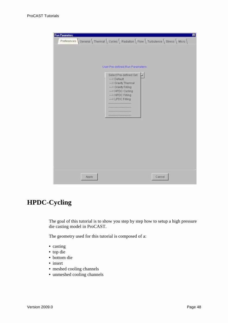
into account for cycle N. It is therefore important to set the right Material type for each component.
Create and Assign the Interfaces between the components In this case all interfaces have to be converted from EQUIV to COINC. In order to validate this choice, press the Apply button.

ProCAST Tutorials
Version 2009.0 Page 55
• Bottom Die - Cooling channels (Standard interface):
Between the bottom die and the meshed cooling channels, a constant heat transfer coefficient of 2000 W/m2K will be set.

ProCAST Tutorials
Version 2009.0 Page 56
• Die - Die interface (Diecombo):
Between the top die and a bottom die a diecombo interface will be set.

ProCAST Tutorials
Version 2009.0 Page 57

ProCAST Tutorials
Version 2009.0 Page 58
• Bottom Die - Insert interface (Diecombo):
Between the bottom die and the insert, a diecombo interface is assigned with a heat transfer coefficient of 1000W/m2K.

ProCAST Tutorials
Version 2009.0 Page 59
• Bottom Die - Casting interface (Diecombo):
• Top Die - Casting interface (Diecombo):

ProCAST Tutorials
Version 2009.0 Page 60
Please note that the casting will be 'attached until ejection' to the top die.
• Top Die - Insert interface (Diecombo):

ProCAST Tutorials
Version 2009.0 Page 61
• Casting - Insert interface (Diecombo):

ProCAST Tutorials
Version 2009.0 Page 62
Assign the Boundary conditions
Air cooling condition will be assigned to the external surface of the mould

ProCAST Tutorials
Version 2009.0 Page 63
Heating channels (200°C) will be assigned to the surfaces of the non-meshed channels using a heat transfer coefficient off 2000W/m2K and an external

ProCAST Tutorials
Version 2009.0 Page 64
temperature of 200°C. The inner surface of the non-meshed channels are selected using the propagate selection tool.
An imposed temperature of 20°C is applied all around the meshed cooling channels.

ProCAST Tutorials
Version 2009.0 Page 65

ProCAST Tutorials
Version 2009.0 Page 66
Set the gravity In order to set the gravity vector, go in the Process menu.
Set the constant Initial conditions

ProCAST Tutorials
Version 2009.0 Page 67

ProCAST Tutorials
Version 2009.0 Page 68
Set the run parameters In the Preferences menu, select the hpdc Cycling option. The right and dedicated run parameters will be automatically set.

ProCAST Tutorials
Version 2009.0 Page 69

ProCAST Tutorials
Version 2009.0 Page 70

ProCAST Tutorials
Version 2009.0 Page 71

ProCAST Tutorials
Version 2009.0 Page 72
9Save and Exit PreCAST
10Run DataCAST and ProCAST

ProCAST Tutorials
Version 2009.0 Page 73
11Visualize the results in ViewCAST

ProCAST Tutorials
Version 2009.0 Page 74
HPDC-Flow
The goal of this tutorial is to show you step by step how to setup a high pressure die casting model in ProCAST. The geometry used for this tutorial is composed of a: • casting • top die • bottom die • insert • meshed cooling channels • unmeshed cooling channels

ProCAST Tutorials
Version 2009.0 Page 75
The goal here was first to run a thermal analysis with several cycles in order to predict the number of necessary cycles to reach steady state. In a second step, the temperature distribution of the mold components will be used as initial temperature for a fluid flow or stress analysis. In this tutorials we are going to extract the die temperature distribution of HPDC-Cycling in order to use it as initial temperature.
Load the hpdcd.dat model in PreCAST Create a new calculation directory and copy from your hpdc-cycling directory the hpdcd.dat and hpdcp.dat files.

ProCAST Tutorials
Version 2009.0 Page 76
Load in PreCAST the hpdcd.dat file:

ProCAST Tutorials
Version 2009.0 Page 77
Modification of the data • MATERIALS: the casting material is set as empty, but the same properties will
be used • INTERFACES: no modifications compared to the HPDC-cycling case, the same
Diecombo interfaces will be used • BOUNDARY CONDITIONS: an imposed temperature and velocity is applied
on the casting inlet.

ProCAST Tutorials
Version 2009.0 Page 78
• PROCESS: no modifications, the same gravity vector is used • INITIAL CONDITIONS: the extract procedure is applied on the top die, bottom
die and insert domains

ProCAST Tutorials
Version 2009.0 Page 79
The temperature distribution at the beginning of cycle number 10 will be considered. In ViewCAST or in the hpdcp.out file it can be determined that this time corresponds to step 765. Using the Browse tool, you can look for the HPDC-Cycling directory where the temperature results of the cycling calculation are.

ProCAST Tutorials
Version 2009.0 Page 80
The temperature distribution can be displayed in order to check that the extract procedure worked.

ProCAST Tutorials
Version 2009.0 Page 81
• RUN PARAMETERS: General and Thermal are not modified, The number of Cycles is set to 1 and Flow is set to 3. The frequency for saving the velocity results (FLOW) is set equal to TFREQ (frequency for saving the temperature results).

ProCAST Tutorials
Version 2009.0 Page 82
ProCAST Tutorials
Version 2009.0 Page 83
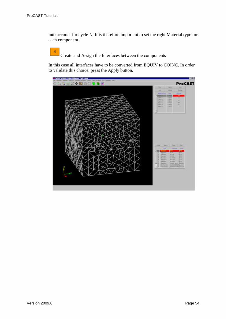
Save and Exit
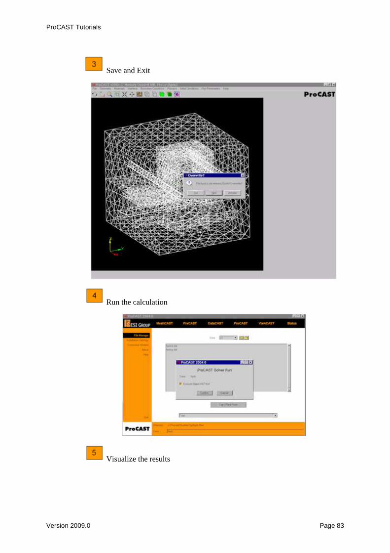
Run the calculation
Visualize the results

ProCAST Tutorials
Version 2009.0 Page 84
Please note that at step zero, the temperature of the die is not uniform as we used the calculated temperature distribution obtained before cycle ten in the HPDC-cycling calculation.

ProCAST Tutorials
Version 2009.0 Page 85

ProCAST Tutorials
Version 2009.0 Page 86

ProCAST Tutorials
Version 2009.0 Page 87
LPDC
The goal of this tutorial is to show step by step how to setup a low pressure die casting model in ProCAST.
The geometry used for this tutorial is composed of a: • casting • left and right side dies • top and bottom cores

ProCAST Tutorials
Version 2009.0 Page 88
Load the lpdcd.dat model in PreCAST
Enter first the case name under the 'Case' field of the file manager and press the PreCAST menu. PreCAST will load first a ProCAST file (d.dat) if it is present in the current directory. If PreCAST does not find any ProCAST file, it will look for a MeshCAST file (.mesh) with the corresponding prefix. And if there is no MeshCAST file, you will have to use the Open file menu of PreCAST in order to look for the right file.

ProCAST Tutorials
Version 2009.0 Page 89

ProCAST Tutorials
Version 2009.0 Page 90
Check the geometry PreCAST indicates automatically the number of materials, the total number of nodes and of elements. The units and the global size of the model are shown. These information and the volume of the different components are available in the File menu -> Check geometry options.

ProCAST Tutorials
Version 2009.0 Page 91
Define the symmetry plane

ProCAST Tutorials
Version 2009.0 Page 92

ProCAST Tutorials
Version 2009.0 Page 93
Assign material properties to the casting, mold and cores. In this case, Cu-Aluminium Bronze is assigned to the casting material, Steel_H13 to both parts of the dies and Sand_Silica to the core domains.

ProCAST Tutorials
Version 2009.0 Page 94
Create and Assign the Interfaces between the components In this case all interfaces are COINC. In case the model would have EQUIV interfaces, they should be converted from EQUIV to COINC. In order to validate this choice, do not forget to press the Apply button.
Once the interfaces are created, assign a heat transfer value to each interface. Typical values are 500 W/m2K between casting and cores and 1000 W/m2K between casting and steel dies.

ProCAST Tutorials
Version 2009.0 Page 95
Assign the Boundary conditions

ProCAST Tutorials
Version 2009.0 Page 96
A natural air cooling heat Boundary condition will be applied all around the dies and a pressure Boundary condition together with a temperature Boundary condition will be imposed at inlet of the gating system. Please note that the simulation model might have a different height compared to the current casting if the full filling column was not taken into account in the simulation model. In such a case the pressure ramp should be shifted accordingly. Please also note that the pressure which is applied to the inlet for the filling sequence will be the difference between the reference pressure which will be defined in the run parameters and this pressure BC. In this case where a total pressure of 0.2 bar is applied, a zero reference pressure will be defined in the FLOW run parameters.
Set the gravity In order to set the gravity vector, go in the Process menu.

ProCAST Tutorials
Version 2009.0 Page 97
Set the constant Initial conditions

ProCAST Tutorials
Version 2009.0 Page 98
9
Set the run parameters In the Preferences menu, select the LPDC filling option. The right and dedicated run parameters will be automatically set.

ProCAST Tutorials
Version 2009.0 Page 99

ProCAST Tutorials
Version 2009.0 Page 100

ProCAST Tutorials
Version 2009.0 Page 101
ProCAST Tutorials
Version 2009.0 Page 102
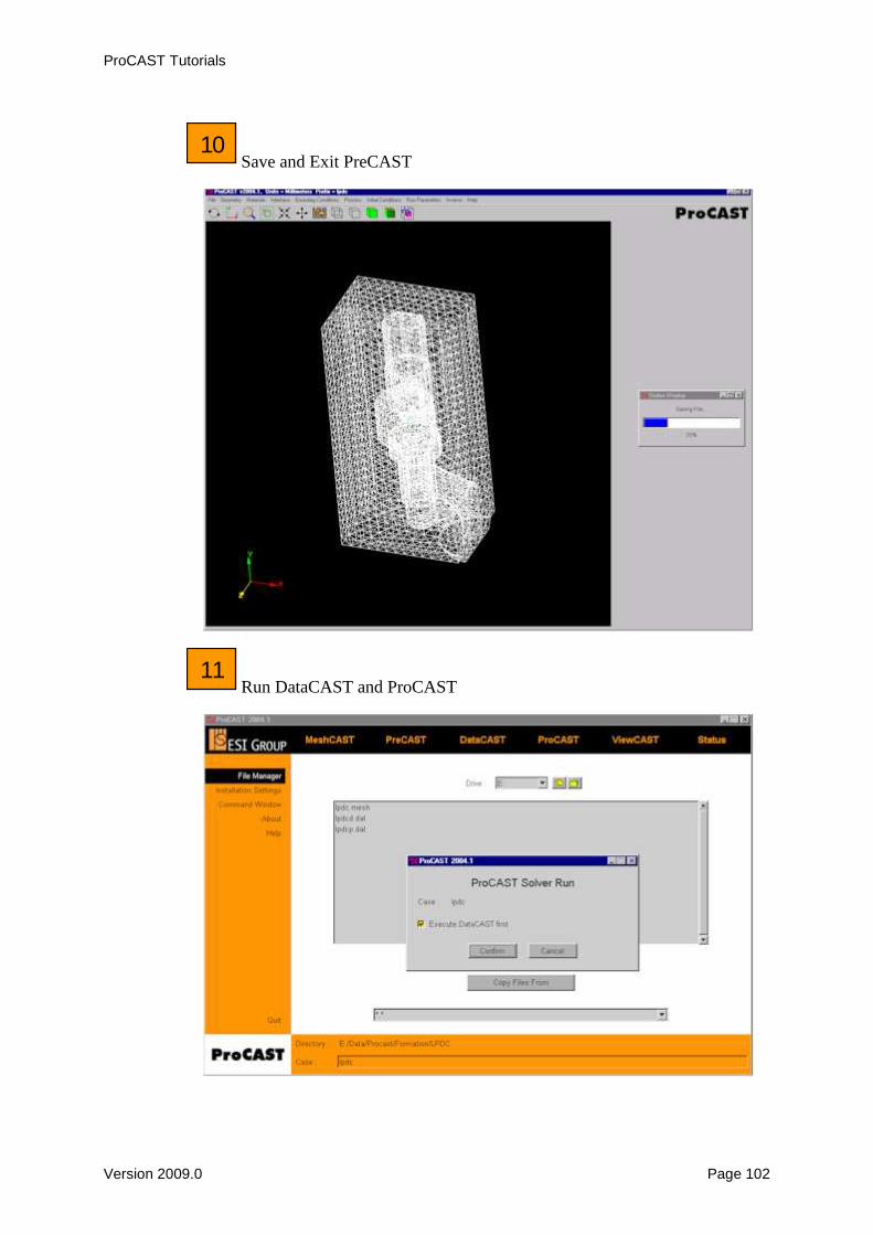
10Save and Exit PreCAST
11Run DataCAST and ProCAST

ProCAST Tutorials
Version 2009.0 Page 103
12 Visualize the results in ViewCAST

ProCAST Tutorials
Version 2009.0 Page 104

ProCAST Tutorials
Version 2009.0 Page 105
Gravity-Sand
This tutorial will guide you step by step in the ProCAST set-up of a sand casting simulation. The geometry used for this tutorial is composed of a: • casting • sand box • cores

ProCAST Tutorials
Version 2009.0 Page 106
Load the sand.mesh model in PreCAST
Please enter first the case name under the 'Case' field of the file manager and press the PreCAST menu.

ProCAST Tutorials
Version 2009.0 Page 107
PreCAST will load first a ProCAST file (d.dat) if it is present in the current directory. If PreCAST does not find any ProCAST file, it will look for a MeshCAST file (.mesh) with the corresponding prefix. And if there is no MeshCAST file, you will have to use the Open file menu of PreCAST in order to look for the right file.

ProCAST Tutorials
Version 2009.0 Page 108

ProCAST Tutorials
Version 2009.0 Page 109
Check the geometry PreCAST indicates automatically the number of materials, the total number of nodes and of elements. The units and the global size of the model are shown. These information and the volume of the different components are available in the File menu -> Check geometry options.

ProCAST Tutorials
Version 2009.0 Page 110
Assign material properties to the casting, mold and cores. In this case, Ductile Iron is assigned to the casting material, Sand silica to the mold and Steel_H13 to the core domains.

ProCAST Tutorials
Version 2009.0 Page 111
Create and Assign the Interfaces between the components In this case all interfaces have to be converted from EQUIV to COINC. In order to validate this choice, press the Apply button.

ProCAST Tutorials
Version 2009.0 Page 112
Once the interfaces are created, assign a heat transfer value to each interface. Typical values are 500 W/m2K between casting and sand and 1000 W/m2K between casting and steel cores.

ProCAST Tutorials
Version 2009.0 Page 113
Assign the Boundary conditions

ProCAST Tutorials
Version 2009.0 Page 114
A natural air cooling heat Boundary condition will be applied all around the sand box, a velocity Boundary condition will be applied and a temperature Boundary condition will be imposed to some nodes of the top surface of the down sprue.

ProCAST Tutorials
Version 2009.0 Page 115
Set the gravity In order to set the gravity vector, go in the Process menu.

ProCAST Tutorials
Version 2009.0 Page 116
Set the constant Initial conditions

ProCAST Tutorials
Version 2009.0 Page 117
Set the run parameters In the Preferences menu, select the Gravity filling option. The right and dedicated run parameters will be automatically set.
In the General run parameters panel, DTMAX is set to 5 seconds in this case.

ProCAST Tutorials
Version 2009.0 Page 118
In the Thermal run parameters panel, TFREQ is set to 5 here.

ProCAST Tutorials
Version 2009.0 Page 119
In the Flow run parameters panel, VFREQ is set to 5 (equal to TFREQ).

ProCAST Tutorials
Version 2009.0 Page 120
Do not forget to press Apply in order to validate the Run Parameters selection.

ProCAST Tutorials
Version 2009.0 Page 121
9Save and Exit PreCAST
10Run DataCAST and ProCAST

ProCAST Tutorials
Version 2009.0 Page 122
11Visualize the results in ViewCAST
Position the model using the picture manipulation tools (zoom, drag, rotate, ...).

ProCAST Tutorials
Version 2009.0 Page 123
Select the casting material.
Visualization of the flow behavior using the 'tape player' buttons.

ProCAST Tutorials
Version 2009.0 Page 124
Analysis of the velocity vectors. Possible mold erosion can be studied.

ProCAST Tutorials
Version 2009.0 Page 125
Temperature map in a cross section through the total model:
Isolated pockets of liquid are displayed using the Fraction of Solid cut-off option.

ProCAST Tutorials
Version 2009.0 Page 126
Investment
The goal of this tutorial is to show you step by step how to setup an investment casting model in ProCAST. The geometry used for this tutorial is composed of a: • casting • a shell mold • an enclosure

ProCAST Tutorials
Version 2009.0 Page 127
• Remark: It is possible to model the preheating of the shell mold in the furnace
using the same model as the one for fluid flow modeling. The temperature distribution of the shell mold is then used as initial condition for the fluid flow calculation using the extract procedure. To do so:

ProCAST Tutorials
Version 2009.0 Page 128
Load the investment.mesh model in PreCAST
Please enter first the case name under the 'Case' field of the file manager and press the PreCAST menu. PreCAST will load first a ProCAST file (d.dat) if it is present in the current directory. If PreCAST does not find any ProCAST file, it will look for a MeshCAST file (.mesh) with the corresponding prefix. And if there is no MeshCAST file, you will have to use the Open file menu of PreCAST in order to look for the right file. If this Case name is not entered, you will have to go in the File menu of PreCAST and open the right file.

ProCAST Tutorials
Version 2009.0 Page 129
Check the geometry PreCAST indicates automatically the number of materials, the total number of nodes and of elements. The units and the global size of the model are shown. These information and the volume of the different components are available in the File menu -> Check geometry options.

ProCAST Tutorials
Version 2009.0 Page 130
Please note that there is an enclosure for the radiation calculation.

ProCAST Tutorials
Version 2009.0 Page 131
Definition of the symmetry planes
Two mirrors of symmetry will be considered here. The Get Co-ord button is useful to pick the node coordinates on the planes of symmetry. You can check that the symmetry was well applied if the symmetry is set in the Boundary conditions.

ProCAST Tutorials
Version 2009.0 Page 132

ProCAST Tutorials
Version 2009.0 Page 133
Assign material properties to the casting and shell mold.
Inconel 718 and a shell material are applied to the casting and shell mold.
Create and Assign the Interfaces between the components In this case all interfaces have to be converted from EQUIV to COINC. In order to validate this choice, press the Apply button.

ProCAST Tutorials
Version 2009.0 Page 134
Assign the interface heat transfer coefficient

ProCAST Tutorials
Version 2009.0 Page 135
Assign the Boundary conditions
In addition to the symmetry Boundary condition, a heat transfer coefficient with View Factors ON will be applied on the surface of the shell. Velocity and temperature will be applied to the top surface of the downsprue.

ProCAST Tutorials
Version 2009.0 Page 136
• Remarks:

ProCAST Tutorials
Version 2009.0 Page 137
A temperature and emissivity has to be applied to the enclosure (Boundary conditions ->Assign Enclosure).

ProCAST Tutorials
Version 2009.0 Page 138
Check that the normals of the enclosure are all pointing inside the enclosure. In case it is not the case, use the Align or Reverse options.

ProCAST Tutorials
Version 2009.0 Page 139
Set the gravity In order to set the gravity vector, go in the Process menu.

ProCAST Tutorials
Version 2009.0 Page 140
Set the constant Initial conditions

ProCAST Tutorials
Version 2009.0 Page 141
9 Set the run parameters
In the Preferences menu, select the Gravity filling option. The right and dedicated run parameters will be automatically set.

ProCAST Tutorials
Version 2009.0 Page 142

ProCAST Tutorials
Version 2009.0 Page 143

ProCAST Tutorials
Version 2009.0 Page 144

ProCAST Tutorials
Version 2009.0 Page 145
10Save and Exit PreCAST
11 Run DataCAST and ProCAST

ProCAST Tutorials
Version 2009.0 Page 146
• Useful tip:
12 Visualize the results in ViewCAST
• Filling results (temperature map)

ProCAST Tutorials
Version 2009.0 Page 147
• Temperature distribution during solidification
• Symmetry re-construction in the Post-processor

ProCAST Tutorials
Version 2009.0 Page 148
• Cross section (temperature map)

ProCAST Tutorials
Version 2009.0 Page 149
• Prediction of pockets of liquid using the fraction of solid field and the cut-off option
Filter
This tutorial will guide you step by step in the ProCAST set-up of a sand casting simulation with a filter material. The geometry used for this tutorial is composed of a: • casting • filter • chill A virtual mold will be generated for the sand mold.

ProCAST Tutorials
Version 2009.0 Page 150
This geometry will also allow the illustration of symmetry settings.
Load the filter.mesh model in PreCAST
Please enter first the case name under the 'Case' field of the file manager and press the PreCAST menu. PreCAST will load first a ProCAST file (d.dat) if it is present in the current directory. If PreCAST does not find any ProCAST file, it will look for a MeshCAST file (.mesh) with the corresponding prefix. And if there is no
ProCAST Tutorials
Version 2009.0 Page 151
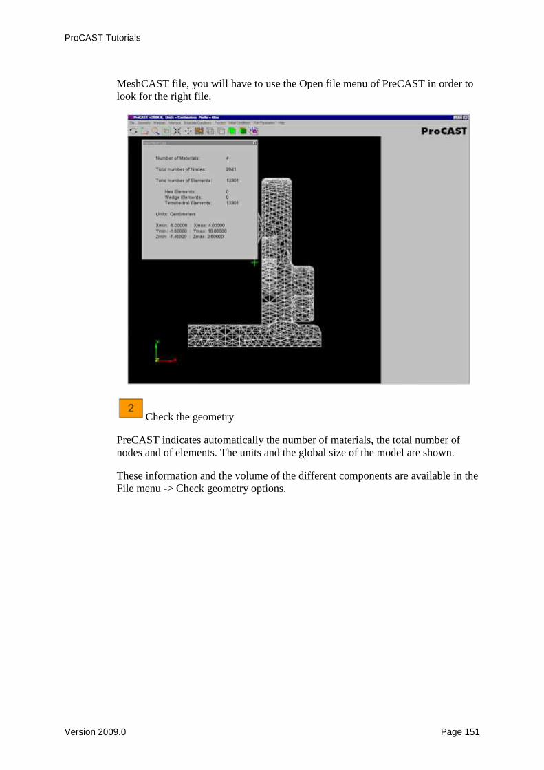
MeshCAST file, you will have to use the Open file menu of PreCAST in order to look for the right file.
Check the geometry PreCAST indicates automatically the number of materials, the total number of nodes and of elements. The units and the global size of the model are shown. These information and the volume of the different components are available in the File menu -> Check geometry options.

ProCAST Tutorials
Version 2009.0 Page 152
Symmetry definition
ProCAST Tutorials
Version 2009.0 Page 153
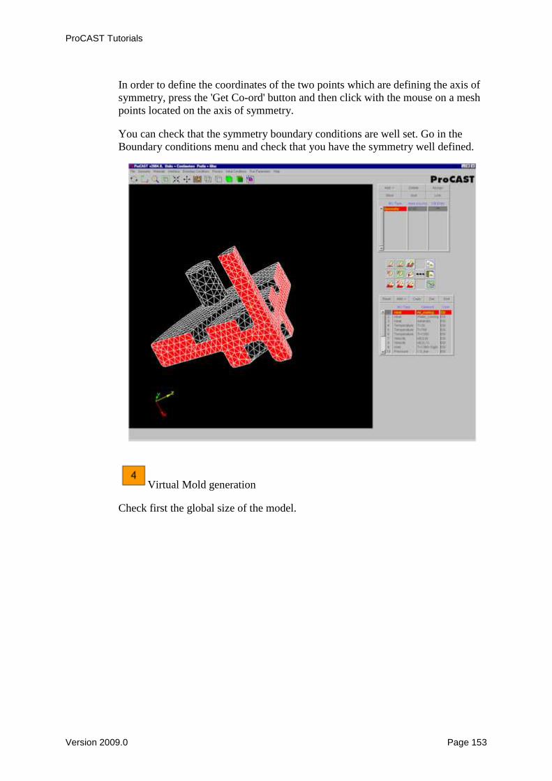
In order to define the coordinates of the two points which are defining the axis of symmetry, press the 'Get Co-ord' button and then click with the mouse on a mesh points located on the axis of symmetry. You can check that the symmetry boundary conditions are well set. Go in the Boundary conditions menu and check that you have the symmetry well defined.
Virtual Mold generation Check first the global size of the model.

ProCAST Tutorials
Version 2009.0 Page 154
Generate a virtual mold larger than the model. The virtual mold has to be large enough as the external boundary of the virtual mold is considered as adiabatic.

ProCAST Tutorials
Version 2009.0 Page 155
You can then visualize the thermal depth.
Assign material properties Please note that the virtual mold will be taken into account and you have thus to assign material properties to the mold.
ProCAST Tutorials
Version 2009.0 Page 156
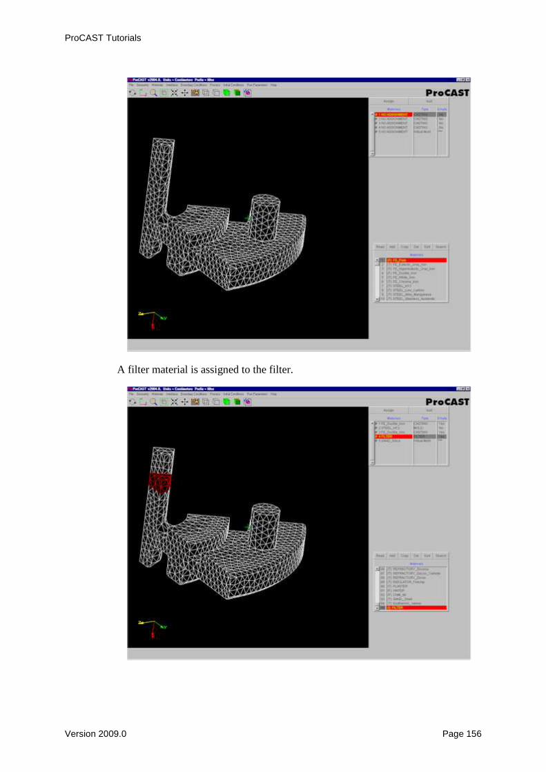
A filter material is assigned to the filter.

ProCAST Tutorials
Version 2009.0 Page 157
In addition to the thermal conductivity, the density and the specific heat, a filter is defined by its Void Fraction and Surface Area (it is also possible to define the Pressure Drop properties - optional).
Create and Assign the Interfaces between the components In this case only the interface between the chill and casting has to be converted from EQUIV to COINC. It is important to note that no interface between the casting and the filter is created. One should thus leave the EQUIV interface type between casting and filter. In order to validate this choice, press the Apply button.

ProCAST Tutorials
Version 2009.0 Page 158
Assign then heat transfer coefficients between the chill and the casting and between all components and the virtual mold. Please note that no heat transfer

ProCAST Tutorials
Version 2009.0 Page 159
coefficient is defined between the casting and the filter. This will be defined in the Assign Volume Boundary Conditions menu.
Assign the Boundary Conditions The symmetry Boundary condition was automatically set as symmetry was defined previously.

ProCAST Tutorials
Version 2009.0 Page 160
A zero velocity Boundary condition has to be applied all around the casting as no coincident meshed mold is considered. A velocity Boundary condition and an imposed temperature are applied to the top of the gating system.

ProCAST Tutorials
Version 2009.0 Page 161
The interface heat transfer coefficient is defined in the Assign Volume -> Filter Heat condition.

ProCAST Tutorials
Version 2009.0 Page 162
Set the gravity
9 Define the Initial Conditions

ProCAST Tutorials
Version 2009.0 Page 163

ProCAST Tutorials
Version 2009.0 Page 164
10Set the Run Parameters
In the Preferences menu, select the Gravity filling option. The right and dedicated run parameters will be automatically set.
In the General run parameters panel, DTMAX is set to 5 seconds and TSTOP is set to1000°C in this case. This means that the calculation will be stopped as soon as the casting domain temperature is below 1000°C.

ProCAST Tutorials
Version 2009.0 Page 165

ProCAST Tutorials
Version 2009.0 Page 166

ProCAST Tutorials
Version 2009.0 Page 167

ProCAST Tutorials
Version 2009.0 Page 168
ProCAST Tutorials
Version 2009.0 Page 169
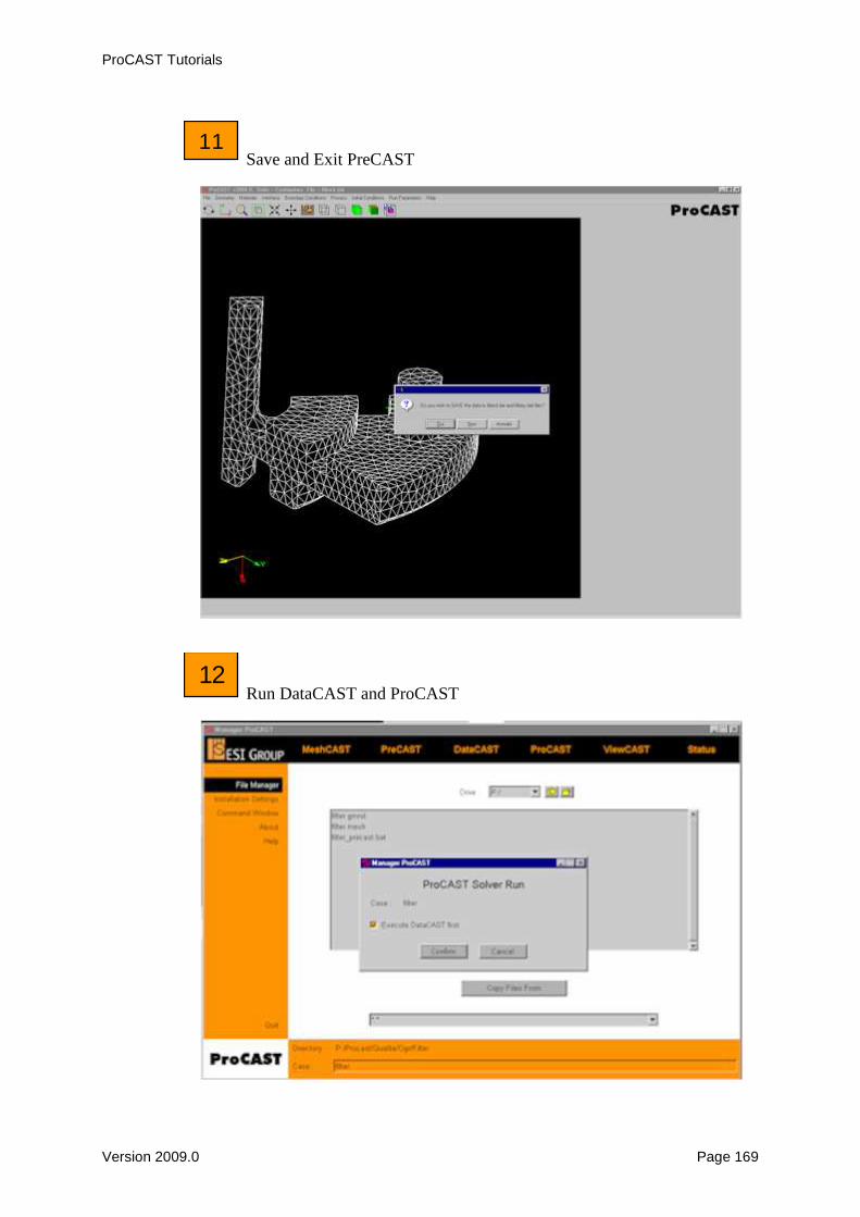
11 Save and Exit PreCAST
12 Run DataCAST and ProCAST

ProCAST Tutorials
Version 2009.0 Page 170
13 Visualize the results in ViewCAST

ProCAST Tutorials
Version 2009.0 Page 171

ProCAST Tutorials
Version 2009.0 Page 172

ProCAST Tutorials
Version 2009.0 Page 173

ProCAST Tutorials
Version 2009.0 Page 174
Stress
This tutorial will guide you step by step in the ProCAST set-up of a stress model. The geometry used for this tutorial is composed of a: • casting • die
Load the stress.mesh model in PreCAST

ProCAST Tutorials
Version 2009.0 Page 175
Please enter first the case name under the 'Case' field of the file manager and press the PreCAST menu. PreCAST will load first a ProCAST file (d.dat) if it is present in the current directory. If PreCAST does not find any ProCAST file, it will look for a MeshCAST file (.mesh) with the corresponding prefix. And if there is no MeshCAST file, you will have to use the Open file menu of PreCAST in order to look for the right file.

ProCAST Tutorials
Version 2009.0 Page 176
PreCAST indicates automatically the number of materials, the total number of nodes and of elements. The units and the global size of the model are shown. These information and the volume of the different components are available in the File menu -> Check geometry options.

ProCAST Tutorials
Version 2009.0 Page 177
Assign material properties to the casting and mold materials.

ProCAST Tutorials
Version 2009.0 Page 178
And assign the corresponding stress properties.

ProCAST Tutorials
Version 2009.0 Page 179
Assign the Interfaces between the components. Please note that the mesh was already optimized in MeshCAST and thus the interfaces are already created (they are already set as COINC).
An interface heat transfer coefficient of 1000W/m2K is selected in the database and assigned between the casting and the dies and between top and bottom die.

ProCAST Tutorials
Version 2009.0 Page 180

ProCAST Tutorials
Version 2009.0 Page 181
Assign the Boundary conditions
A natural air cooling heat Boundary condition is assigned all around the die and a zero displacement Boundary condition is applied to the top and bottom surface of the die.

ProCAST Tutorials
Version 2009.0 Page 182

ProCAST Tutorials
Version 2009.0 Page 183
Set the gravity In order to set the gravity vector, go in the Process menu.

ProCAST Tutorials
Version 2009.0 Page 184
Set the constant Initial conditions

ProCAST Tutorials
Version 2009.0 Page 185
Set the run parameters

ProCAST Tutorials
Version 2009.0 Page 186

ProCAST Tutorials
Version 2009.0 Page 187
Please be careful to set PIPEFS to zero. Do not forget to press Apply in order to validate the Run Parameters selection.
9Save and Exit PreCAST

ProCAST Tutorials
Version 2009.0 Page 188
10Run DataCAST and ProCAST

ProCAST Tutorials
Version 2009.0 Page 189
11Visualize the results in ViewCAST
Temperature results:

ProCAST Tutorials
Version 2009.0 Page 190

ProCAST Tutorials
Version 2009.0 Page 191
Effective stress results:
Y-Displacements:

ProCAST Tutorials
Version 2009.0 Page 192
Hot tearing prediction:
ProCAST Tutorials
Version 2009.0 Page 193
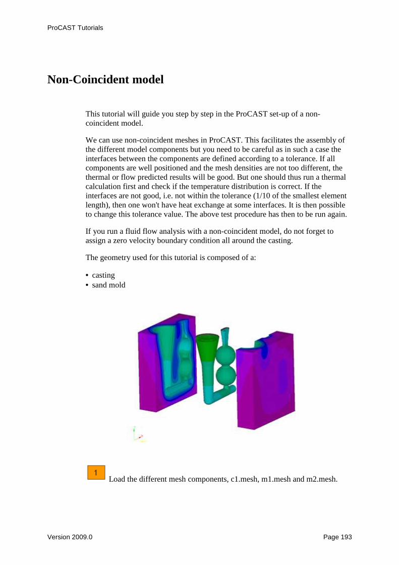
Non-Coincident model
This tutorial will guide you step by step in the ProCAST set-up of a non-coincident model. We can use non-coincident meshes in ProCAST. This facilitates the assembly of the different model components but you need to be careful as in such a case the interfaces between the components are defined according to a tolerance. If all components are well positioned and the mesh densities are not too different, the thermal or flow predicted results will be good. But one should thus run a thermal calculation first and check if the temperature distribution is correct. If the interfaces are not good, i.e. not within the tolerance (1/10 of the smallest element length), then one won't have heat exchange at some interfaces. It is then possible to change this tolerance value. The above test procedure has then to be run again. If you run a fluid flow analysis with a non-coincident model, do not forget to assign a zero velocity boundary condition all around the casting. The geometry used for this tutorial is composed of a: • casting • sand mold
Load the different mesh components, c1.mesh, m1.mesh and m2.mesh.

ProCAST Tutorials
Version 2009.0 Page 194
No prefix is entered in this case in the file manager (Case field) as you are going to load the models using the Multiple Mesh option in the File menu

ProCAST Tutorials
Version 2009.0 Page 195

ProCAST Tutorials
Version 2009.0 Page 196
Check the geometry PreCAST indicates automatically the number of materials, the total number of nodes and of elements. The units and the global size of the model are shown. These information and the volume of the different components are available in the File menu -> Check geometry options.

ProCAST Tutorials
Version 2009.0 Page 197
Assign material properties to the casting and to both mold sides

ProCAST Tutorials
Version 2009.0 Page 198
Create and Assign the Interfaces between the components One coincident interface was recognized in this case (even if both models are not coincident) between both mold components because one element is most probably exactly coincident on each mold side.
In case of a non-coincident model one has to turn the coincident interface type in non-coincident and add the other non-coincident interfaces. Please note that the casting is the Master and the Mold is the Slave.

ProCAST Tutorials
Version 2009.0 Page 199
Do not forget to Apply the non-coincident interfaces and to assign an interface heat transfer coefficient between the different interfaces.

ProCAST Tutorials
Version 2009.0 Page 200
Assign the Boundary conditions

ProCAST Tutorials
Version 2009.0 Page 201

ProCAST Tutorials
Version 2009.0 Page 202

ProCAST Tutorials
Version 2009.0 Page 203
As a summary the boundary conditions are: • Heat: air cooling all around the mould

ProCAST Tutorials
Version 2009.0 Page 204
• Velocity: zero velocity all around the casting (this necessary in case of a no-coincident mold, in case of virtual mold or in case there is no mold)
• Velocity: -y velocity at the top of the downsprue. • Temperature: Pouring temperature of the metal assigned at the top of the
downsprue.
Set the gravity In order to set the gravity vector, go in the Process menu.

ProCAST Tutorials
Version 2009.0 Page 205
Set the constant Initial conditions

ProCAST Tutorials
Version 2009.0 Page 206
Set the run parameters In the Preferences menu, select the Gravity filling option. The right and dedicated run parameters will be automatically set.

ProCAST Tutorials
Version 2009.0 Page 207

ProCAST Tutorials
Version 2009.0 Page 208

ProCAST Tutorials
Version 2009.0 Page 209

ProCAST Tutorials
Version 2009.0 Page 210
9Save and Exit PreCAST

ProCAST Tutorials
Version 2009.0 Page 211
10Run DataCAST and ProCAST
11Visualize the results in ViewCAST

ProCAST Tutorials
Version 2009.0 Page 212

ProCAST Tutorials
Version 2009.0 Page 213