Embed Size (px)
DESCRIPTION
solutions to some selected problems on force systemcollected from www.mathalino.com
Citation preview
Problems on
Coplanar concurrent, non-concurrent and parallel
Force Systems
Assignment by: Md. Kamrul Ahsan Lecturer, Dept. of Civil Engineering, Khulna University of Engineering & Technology, Khulna
Problems Source: http://www.mathalino.com
Solves Collected and Composed by: Tariqul Islam (1301047),
Dept. of Civil Engineering, Khulna University of Engineering & Technology, Khulna
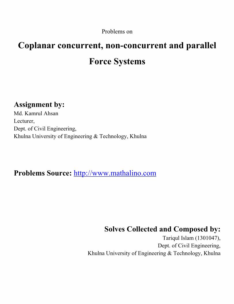
Problem 01 The magnitude of vertical force F shown in Fig. P-016 is 8000 N. Resolve F into components parallel to the bars AB and AC.
Solution
By Sine Law:
° °
4256.71 answer
° °
10778.37 answer

Problem 02 If the force F shown in Fig. P-017 is resolved into components parallel to the bars AB and BC, the magnitude of the component parallel to bar BC is 4 kN. What are the magnitudes of F and its component parallel to AB?
Solution
.
.
56.31°
.
.
20.56°
90° 90° 56.31°
33.69°
90° 90° 20.56°
69.44°
180° 180° 33.69° 69.44°
76.87°
By Sine law
. °
. °
7.02 answer
. °
. °
6.75 answer
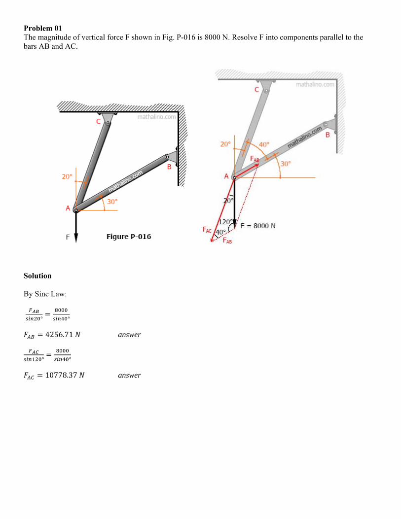
Problem 03 A vertical force P at A and another vertical force F at B in Fig. P-251 produce a resultant of 100 lb down at D and a counterclockwise couple C of 200 lb·ft. Find the magnitude and direction of forces P and F.
Solution
7
3 7 100 200
300 answer
∑
100
300 100
200 answer

Problem 04 A parallel force system acts on the lever shown in Fig. P-236. Determine the magnitude and position of the resultant.
Solution
∑ 30 60 20 40 110 downward
∑
2 30 5 60 7 20 11 40
660 . clockwise
110 660
6 to the right of A
Thus, R = 110 lb downward at 6 ft to the right of A. answer

Problem 05 The beam AB in Fig. P-238 supports a load which varies an intensity of 220 N/m to 890 N/m. Calculate the magnitude and position of the resultant load.
Solution
6 220 1320
6 670 2010
1320 2010
3330
3 4
3330 3 1320 4 2010
3330 12000
3.6
Thus, R = 3330 N downward at 3.6 m to the left of A. answer

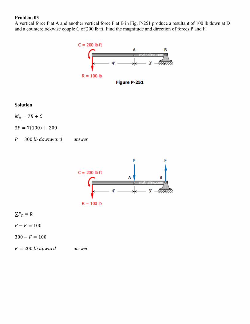
Problem 06 The cable and boom shown in Fig. P-308 support a load of 600 lb. Determine the tensile force T in the cable and the compressive for C in the boom.
Solution
∑ 0
45° 30° 1.2247
∑ 0
30° 45° 600
30° 1.2247 45° 600
1.366 600
439.24 answer
1.2247 439.24
537.94 answer
Another Solution (By Rotation of Axes)
∑ 0 75° 600 45° 439.23 (okay!)
∑ 0
75° 600 45° 439.23 75° 600 45° 537.94 (okay!)
Another Solution (By Force Polygon)
° ° °
439.23 (okay!)
537.94 (okay!)
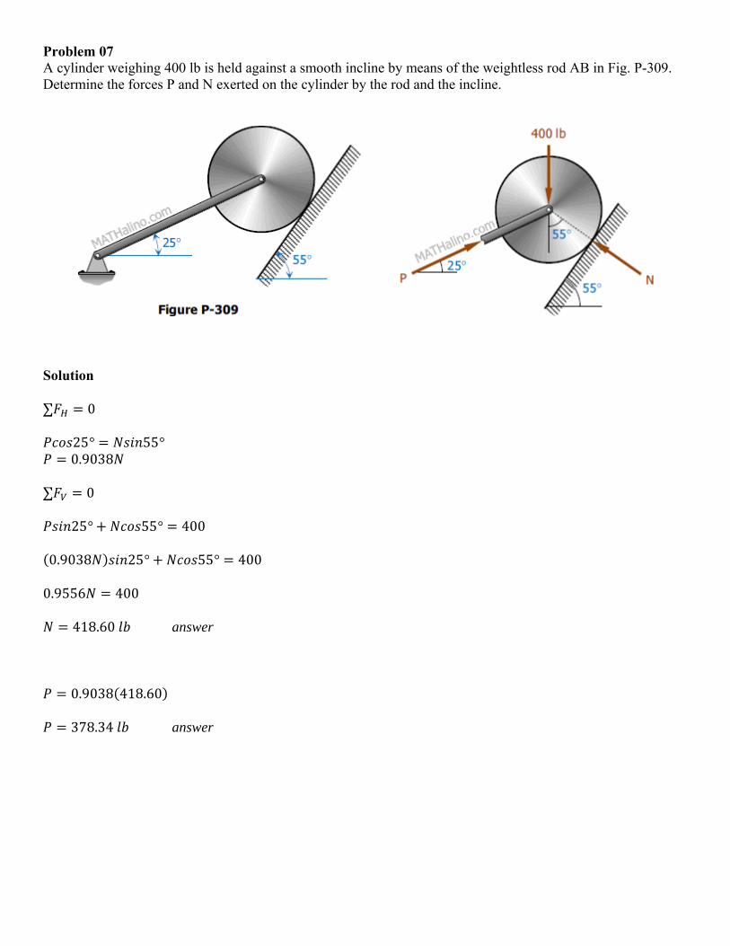
Problem 07 A cylinder weighing 400 lb is held against a smooth incline by means of the weightless rod AB in Fig. P-309. Determine the forces P and N exerted on the cylinder by the rod and the incline.
Solution
∑ 0
25° 55° 0.9038
∑ 0
25° 55° 400
0.9038 25° 55° 400
0.9556 400
418.60 answer
0.9038 418.60
378.34 answer
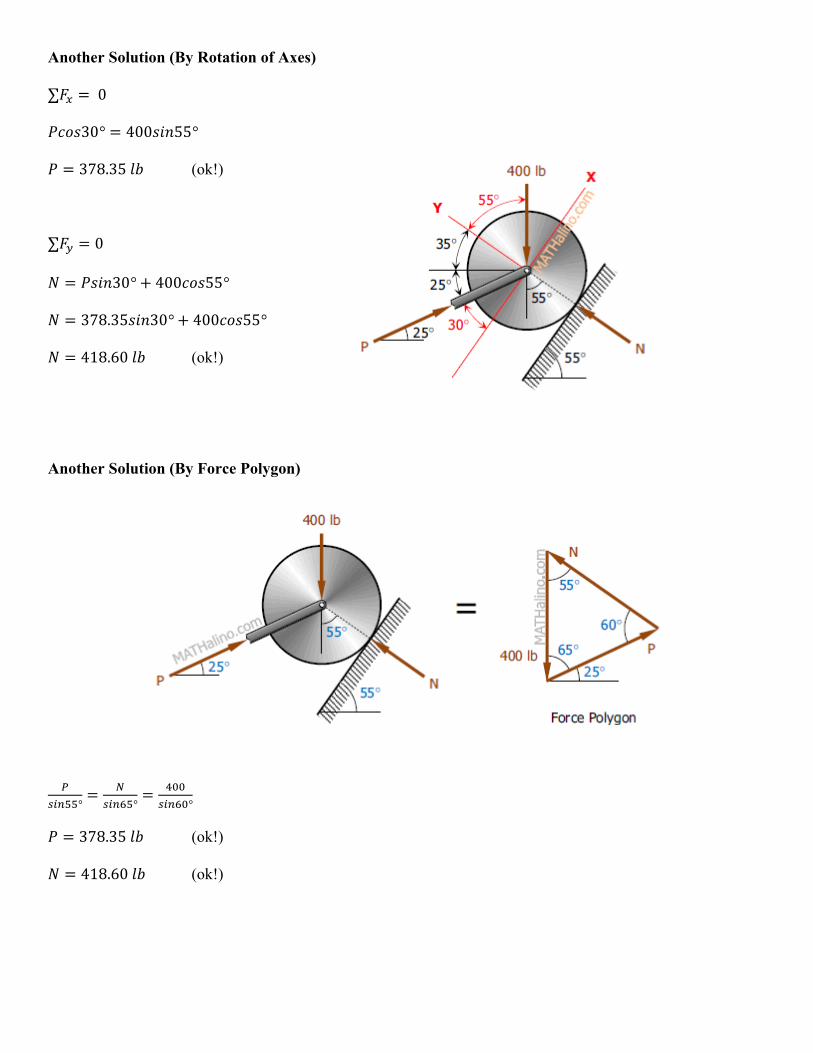
Another Solution (By Rotation of Axes)
∑ 0
30° 400 55°
378.35 (ok!)
∑ 0
30° 400 55°
378.35 30° 400 55°
418.60 (ok!)
Another Solution (By Force Polygon)
° ° °
378.35 (ok!)
418.60 (ok!)
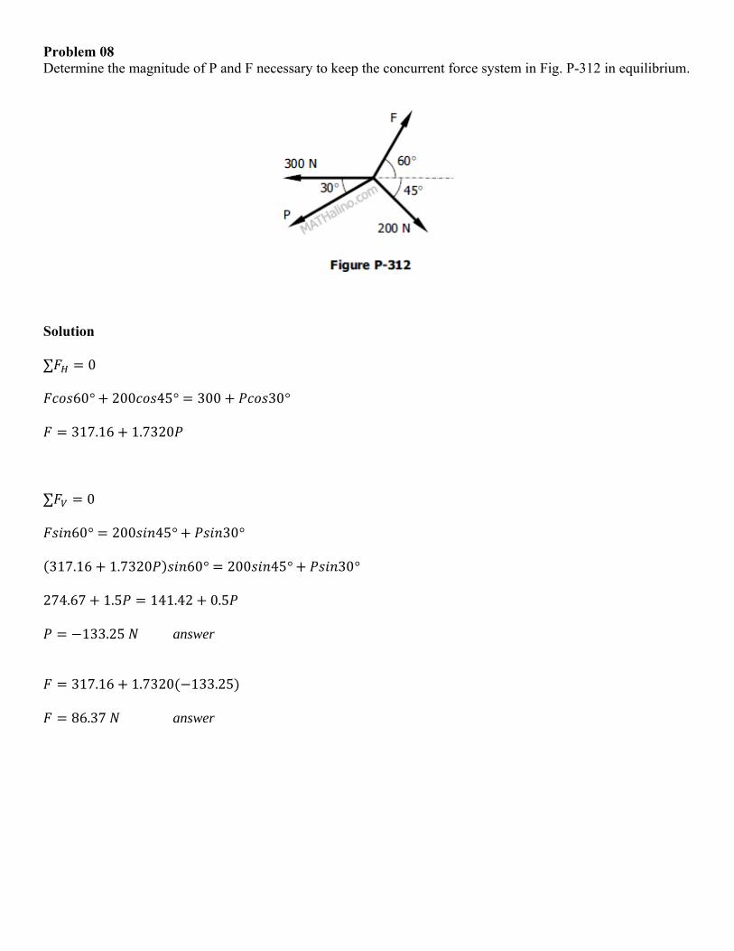
Problem 08 Determine the magnitude of P and F necessary to keep the concurrent force system in Fig. P-312 in equilibrium.
Solution
∑ 0
60° 200 45° 300 30°
317.16 1.7320
∑ 0
60° 200 45° 30°
317.16 1.7320 60° 200 45° 30°
274.67 1.5 141.42 0.5
133.25 answer
317.16 1.7320 133.25
86.37 answer
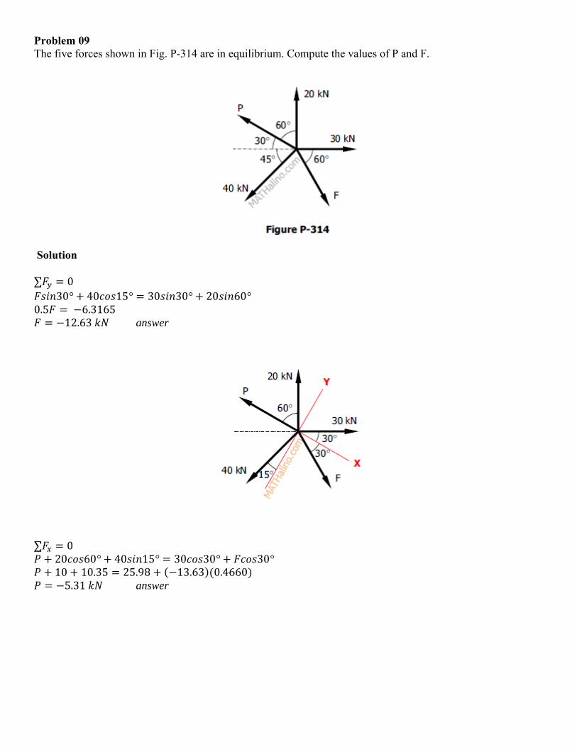
Problem 09 The five forces shown in Fig. P-314 are in equilibrium. Compute the values of P and F.
Solution
∑ 0 30° 40 15° 30 30° 20 60°
0.5 6.3165 12.63 answer
∑ 0 20 60° 40 15° 30 30° 30° 10 10.35 25.98 13.63 0.4660 5.31 answer

Problem 10 The system of knotted cords shown in Fig. P-317 support the indicated weights. Compute the tensile force in each cord.
Solution
From the knot where 400-lb load is hanging ∑ 0
75° 30° 0.5176
∑ 0
75° 30° 400 0.5176 75° 30° 400
400 answer
0.5176 400 207.06 answer
From the knot where 300-lb load is hanging
∑ 0
45° 300 30° 45° 300 400 30° 914.16 answer
∑ 0
45° 30° 914.16 45° 400 30° 846.41 answer
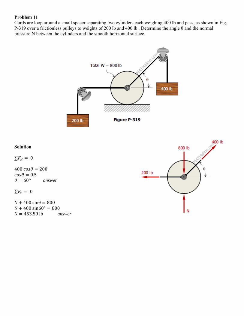
Problem 11 Cords are loop around a small spacer separating two cylinders each weighing 400 lb and pass, as shown in Fig. P-319 over a frictionless pulleys to weights of 200 lb and 400 lb . Determine the angle θ and the normal pressure N between the cylinders and the smooth horizontal surface.
Solution
∑ 0 400 200
0.5 60° answer
∑ 0 N 400sinθ 800 N 400sin60° 800 N 453.59lb answer
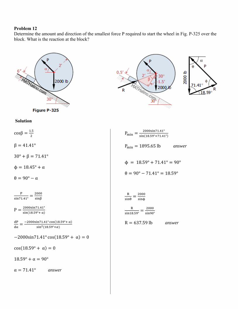
Problem 12 Determine the amount and direction of the smallest force P required to start the wheel in Fig. P-325 over the block. What is the reaction at the block?
Solution
cosβ.
β 41.41°
30° β 71.41°
ϕ 18.45° α
θ 90° α
. °
P. °
. °
. ° . °
. °
2000sin71.41° cos 18.59° α 0
cos 18.59° α 0
18.59° α 90°
α 71.41° answer
P. °
. ° . °
P 1895.65lb answer
ϕ 18.59° 71.41° 90°
θ 90° 71.41° 18.59°
. ° °
R 637.59lb answer
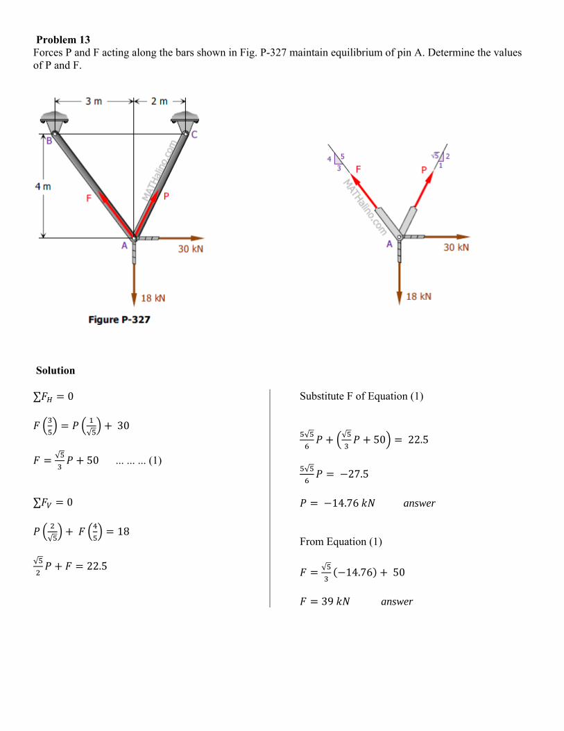
Problem 13 Forces P and F acting along the bars shown in Fig. P-327 maintain equilibrium of pin A. Determine the values of P and F.
Solution
∑ 0
√30
√50 ... ... ... (1)
∑ 0
√ 18
√22.5
Substitute F of Equation (1)
√ √
50 22.5
√ 27.5
14.76 answer
From Equation (1)
√14.76 50
39 answer
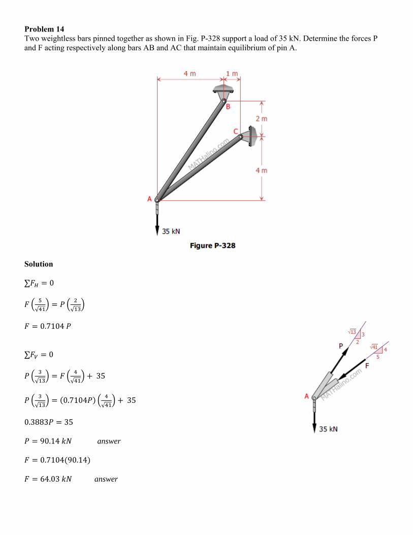
Problem 14 Two weightless bars pinned together as shown in Fig. P-328 support a load of 35 kN. Determine the forces P and F acting respectively along bars AB and AC that maintain equilibrium of pin A.
Solution
∑ 0
√ √
0.7104
∑ 0
√ √35
√0.7104
√35
0.3883 35
90.14 answer
0.7104 90.14
64.03 answer
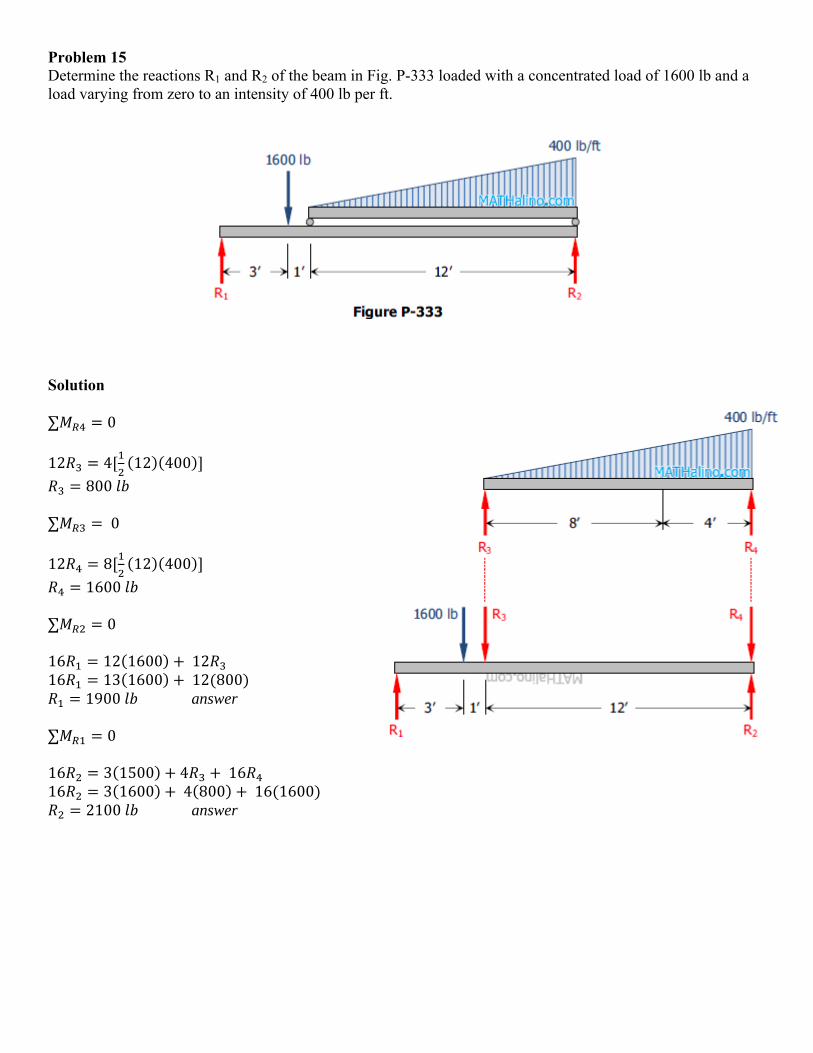
Problem 15 Determine the reactions R1 and R2 of the beam in Fig. P-333 loaded with a concentrated load of 1600 lb and a load varying from zero to an intensity of 400 lb per ft.
Solution
∑ 0
12 4 12 400
800 ∑ 0
12 8 12 400
1600 ∑ 0 16 12 1600 12 16 13 1600 12 800
1900 answer ∑ 0 16 3 1500 4 16 16 3 1600 4 800 16 1600
2100 answer
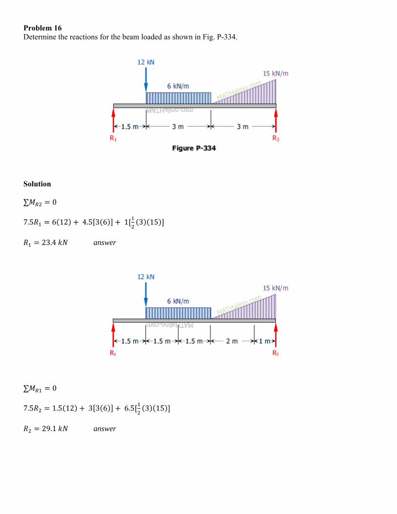
Problem 16 Determine the reactions for the beam loaded as shown in Fig. P-334.
Solution
∑ 0
7.5 6 12 4.5 3 6 1 3 15
23.4 answer
∑ 0
7.5 1.5 12 3 3 6 6.5 3 15
29.1 answer
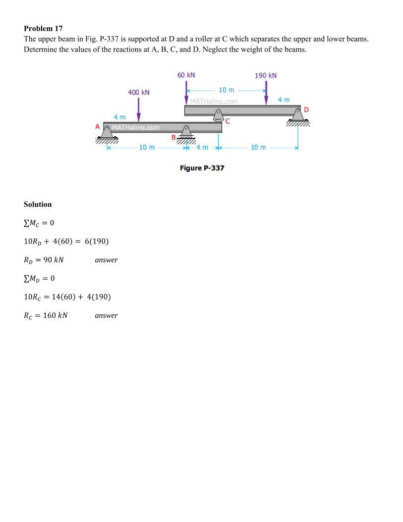
Problem 17 The upper beam in Fig. P-337 is supported at D and a roller at C which separates the upper and lower beams. Determine the values of the reactions at A, B, C, and D. Neglect the weight of the beams.
Solution
∑ 0
10 4 60 6 190
90 answer
∑ 0
10 14 60 4 190
160 answer
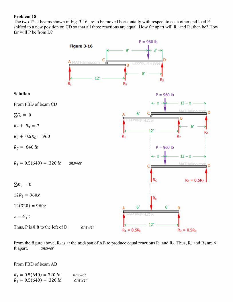
Problem 18 The two 12-ft beams shown in Fig. 3-16 are to be moved horizontally with respect to each other and load P shifted to a new position on CD so that all three reactions are equal. How far apart will R2 and R3 then be? How far will P be from D?
Solution
From FBD of beam CD
∑ 0
0.5 960
640
0.5 640 320 answer
∑ 0
12 960
12 320 960
4
Thus, P is 8 ft to the left of D. answer
From the figure above, Rc is at the midspan of AB to produce equal reactions R1 and R2. Thus, R2 and R3 are 6 ft apart. answer
From FBD of beam AB
0.5 640 320 answer 0.5 640 320 answer
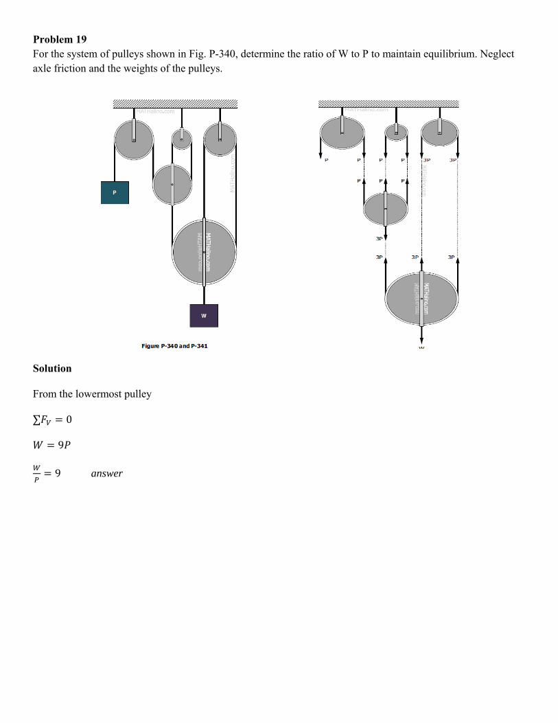
Problem 19 For the system of pulleys shown in Fig. P-340, determine the ratio of W to P to maintain equilibrium. Neglect axle friction and the weights of the pulleys.
Solution
From the lowermost pulley
∑ 0
9
9 answer
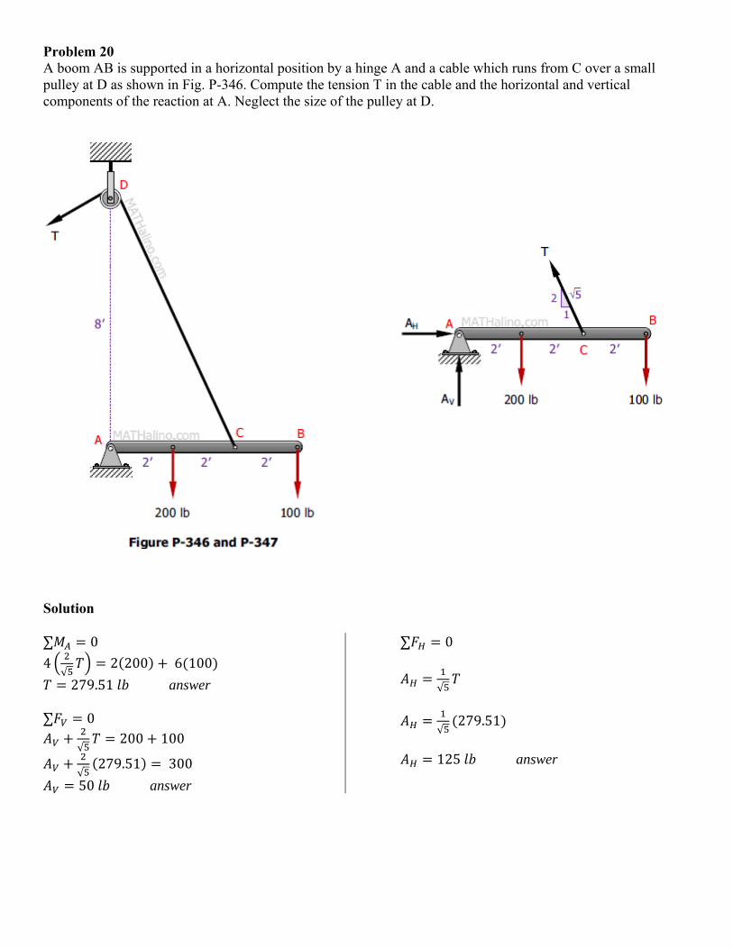
Problem 20 A boom AB is supported in a horizontal position by a hinge A and a cable which runs from C over a small pulley at D as shown in Fig. P-346. Compute the tension T in the cable and the horizontal and vertical components of the reaction at A. Neglect the size of the pulley at D.
Solution
∑ 0
4√
2 200 6 100
279.51 answer ∑ 0
√200 100
√279.51 300
50 answer
∑ 0
√
√279.51
125 answer
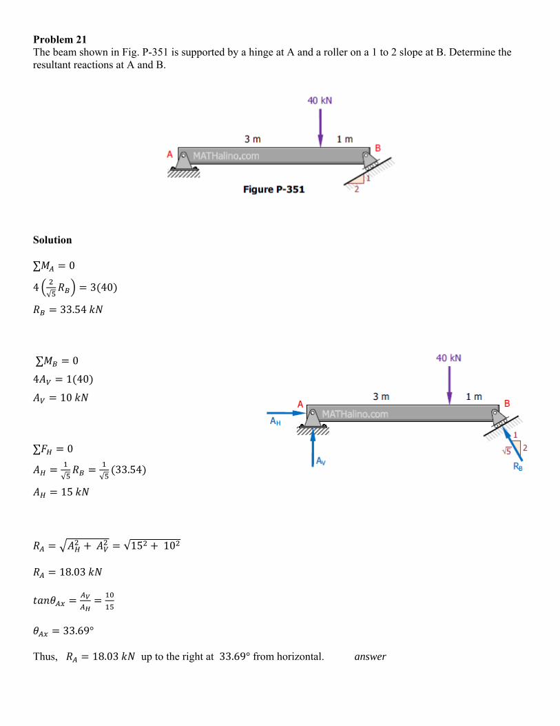
Problem 21 The beam shown in Fig. P-351 is supported by a hinge at A and a roller on a 1 to 2 slope at B. Determine the resultant reactions at A and B.
Solution
∑ 0
4√
3 40
33.54
∑ 0
4 1 40
10
∑ 0
√ √33.54
15
√15 10
18.03
33.69°
Thus, 18.03 up to the right at 33.69° from horizontal. answer
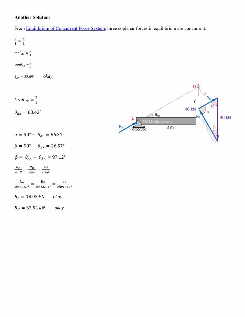
Another Solution
From Equilibrium of Concurrent Force System, three coplanar forces in equilibrium are concurrent.
tanθ
33.69° okay
63.43°
90° 56.31°
90° 26.57°
97.12°
. ° . ° . °
18.03 okay
33.54 okay
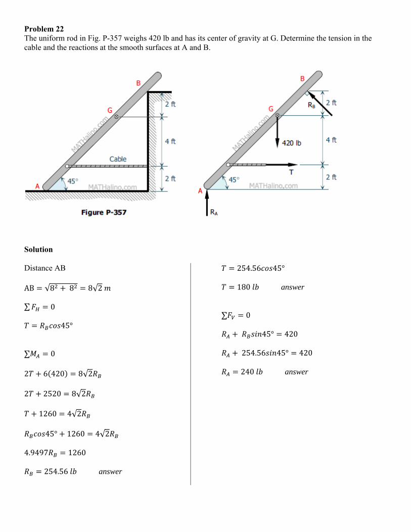
Problem 22 The uniform rod in Fig. P-357 weighs 420 lb and has its center of gravity at G. Determine the tension in the cable and the reactions at the smooth surfaces at A and B.
Solution
Distance AB AB √8 8 8√2 ∑ 0
45°
∑ 0
2 6 420 8√2
2 2520 8√2
1260 4√2
45° 1260 4√2
4.9497 1260
254.56 answer
254.56 45°
180 answer
∑ 0
45° 420
254.56 45° 420
240 answer
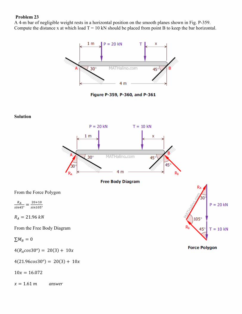
Problem 23 A 4-m bar of negligible weight rests in a horizontal position on the smooth planes shown in Fig. P-359. Compute the distance x at which load T = 10 kN should be placed from point B to keep the bar horizontal.
Solution
From the Force Polygon
° °
21.96
From the Free Body Diagram
∑ 0
4 30° 20 3 10
4 21.96 30° 20 3 10
10 16.072
1.61 answer