Embed Size (px)
Citation preview

IBM System Storage DS4000
Problem Determination Guide
GC27-2076-00
���

IBM System Storage DS4000
Problem Determination Guide
GC27-2076-00
���

Note
Before using this information and the product it supports, be sure to read the general information in “Notices” on page 193.
First Edition (August 2006)
© Copyright International Business Machines Corporation 2006. All rights reserved.
US Government Users Restricted Rights – Use, duplication or disclosure restricted by GSA ADP Schedule Contract
with IBM Corp.
Contents
Figures . . . . . . . . . . . . . . . . . . . . . . . . . . . . . . . . . . . vii
Tables . . . . . . . . . . . . . . . . . . . . . . . . . . . . . . . . . . . . ix
Safety . . . . . . . . . . . . . . . . . . . . . . . . . . . . . . . . . . . . xi
Caution and danger notices . . . . . . . . . . . . . . . . . . . . . . . . . . . . . . xii
Safety information . . . . . . . . . . . . . . . . . . . . . . . . . . . . . . . . . xvi
General safety . . . . . . . . . . . . . . . . . . . . . . . . . . . . . . . . . xvi
Grounding requirements . . . . . . . . . . . . . . . . . . . . . . . . . . . . . xvii
Electrical safety . . . . . . . . . . . . . . . . . . . . . . . . . . . . . . . . xvii
Handling ESD-sensitive devices . . . . . . . . . . . . . . . . . . . . . . . . . . . xviii
Safety inspection procedure . . . . . . . . . . . . . . . . . . . . . . . . . . . . . xix
About this document . . . . . . . . . . . . . . . . . . . . . . . . . . . . . xxi
FAStT product renaming . . . . . . . . . . . . . . . . . . . . . . . . . . . . . . . xxi
Who should read this document . . . . . . . . . . . . . . . . . . . . . . . . . . . . xxii
How this document is organized . . . . . . . . . . . . . . . . . . . . . . . . . . . . xxii
Notices used in this document . . . . . . . . . . . . . . . . . . . . . . . . . . . . xxiii
Getting information, help, and service . . . . . . . . . . . . . . . . . . . . . . . . . . xxiv
Before you call . . . . . . . . . . . . . . . . . . . . . . . . . . . . . . . . xxiv
Using the documentation . . . . . . . . . . . . . . . . . . . . . . . . . . . . . xxiv
Web sites . . . . . . . . . . . . . . . . . . . . . . . . . . . . . . . . . . xxiv
Software service and support . . . . . . . . . . . . . . . . . . . . . . . . . . . . xxv
Hardware service and support . . . . . . . . . . . . . . . . . . . . . . . . . . . xxv
Fire suppression systems . . . . . . . . . . . . . . . . . . . . . . . . . . . . . xxv
How to send your comments . . . . . . . . . . . . . . . . . . . . . . . . . . . . xxvi
Chapter 1. About problem determination . . . . . . . . . . . . . . . . . . . . . . 1
Where to start . . . . . . . . . . . . . . . . . . . . . . . . . . . . . . . . . . . 1
Related documents . . . . . . . . . . . . . . . . . . . . . . . . . . . . . . . . . 1
Product updates . . . . . . . . . . . . . . . . . . . . . . . . . . . . . . . . . . 2
Chapter 2. Problem determination starting points . . . . . . . . . . . . . . . . . . 3
Problem determination tools . . . . . . . . . . . . . . . . . . . . . . . . . . . . . . 3
Considerations before starting PD maps . . . . . . . . . . . . . . . . . . . . . . . . . . 4
File updates . . . . . . . . . . . . . . . . . . . . . . . . . . . . . . . . . . 5
Starting points for problem determination . . . . . . . . . . . . . . . . . . . . . . . . . 5
General symptoms . . . . . . . . . . . . . . . . . . . . . . . . . . . . . . . . 5
Specific problem areas . . . . . . . . . . . . . . . . . . . . . . . . . . . . . . . 5
PD maps and diagrams . . . . . . . . . . . . . . . . . . . . . . . . . . . . . . . 6
Chapter 3. Problem determination maps . . . . . . . . . . . . . . . . . . . . . . 7
Configuration Type PD map . . . . . . . . . . . . . . . . . . . . . . . . . . . . . . 8
RAID Controller Passive PD map . . . . . . . . . . . . . . . . . . . . . . . . . . . . 9
Cluster Resource PD map . . . . . . . . . . . . . . . . . . . . . . . . . . . . . . 10
Start Delay PD map . . . . . . . . . . . . . . . . . . . . . . . . . . . . . . . . 11
Systems Management PD map . . . . . . . . . . . . . . . . . . . . . . . . . . . . . 12
Hub/Switch PD map 1 . . . . . . . . . . . . . . . . . . . . . . . . . . . . . . . 13
Hub/Switch PD map 2 . . . . . . . . . . . . . . . . . . . . . . . . . . . . . . . 14
Check Connections PD map . . . . . . . . . . . . . . . . . . . . . . . . . . . . . . 15
Fibre Path PD map 1 . . . . . . . . . . . . . . . . . . . . . . . . . . . . . . . . 16
Fibre Path PD map 2 . . . . . . . . . . . . . . . . . . . . . . . . . . . . . . . . 17
Single Path Fail PD map 1 . . . . . . . . . . . . . . . . . . . . . . . . . . . . . . 18
Single Path Fail PD map 2 . . . . . . . . . . . . . . . . . . . . . . . . . . . . . . 19
© Copyright IBM Corp. 2006 iii

Common Path PD map 1 . . . . . . . . . . . . . . . . . . . . . . . . . . . . . . . 20
Common Path PD map 2 . . . . . . . . . . . . . . . . . . . . . . . . . . . . . . . 21
Device PD map 1 . . . . . . . . . . . . . . . . . . . . . . . . . . . . . . . . . 22
Device PD map 2 . . . . . . . . . . . . . . . . . . . . . . . . . . . . . . . . . 23
Linux Port Configuration PD map 1 . . . . . . . . . . . . . . . . . . . . . . . . . . . 24
Linux Port Configuration PD map 2 . . . . . . . . . . . . . . . . . . . . . . . . . . . 25
pSeries PD map . . . . . . . . . . . . . . . . . . . . . . . . . . . . . . . . . . 26
Fibre Channel Adapter Not Available PD map . . . . . . . . . . . . . . . . . . . . . . . . 28
Fibre Channel SCSI I/O Controller Protocol Device Not Available PD map . . . . . . . . . . . . . . 29
Logical Hard Disks Not Available PD map . . . . . . . . . . . . . . . . . . . . . . . . . 30
Logical Tape Drives Not Available PD map . . . . . . . . . . . . . . . . . . . . . . . . . 31
Fiber Path Failures PD map 1 . . . . . . . . . . . . . . . . . . . . . . . . . . . . . 32
Fibre Path Failures PD map 2 . . . . . . . . . . . . . . . . . . . . . . . . . . . . . 33
Chapter 4. Introduction to the QLogic SANsurfer application . . . . . . . . . . . . 35
SAN environment . . . . . . . . . . . . . . . . . . . . . . . . . . . . . . . . . 35
SANsurfer Overview . . . . . . . . . . . . . . . . . . . . . . . . . . . . . . . . 35
SANsurfer system requirements . . . . . . . . . . . . . . . . . . . . . . . . . . . . 36
SANsurfer client interface . . . . . . . . . . . . . . . . . . . . . . . . . . . . . 36
Host agent . . . . . . . . . . . . . . . . . . . . . . . . . . . . . . . . . . . 36
Limitations . . . . . . . . . . . . . . . . . . . . . . . . . . . . . . . . . . 37
Installing the SANsurfer FC HBA Manager . . . . . . . . . . . . . . . . . . . . . . . . . 38
Initial installation . . . . . . . . . . . . . . . . . . . . . . . . . . . . . . . . 38
Uninstalling the SANsurfer applications software . . . . . . . . . . . . . . . . . . . . . . 50
SANsurfer FC HBA Manager features . . . . . . . . . . . . . . . . . . . . . . . . . . 55
QLogic SANsurfer basic features overview . . . . . . . . . . . . . . . . . . . . . . . . . 56
Features . . . . . . . . . . . . . . . . . . . . . . . . . . . . . . . . . . . 56
Options . . . . . . . . . . . . . . . . . . . . . . . . . . . . . . . . . . . . 56
Connecting to hosts . . . . . . . . . . . . . . . . . . . . . . . . . . . . . . . 58
Disconnecting from a host . . . . . . . . . . . . . . . . . . . . . . . . . . . . . 59
Polling interval . . . . . . . . . . . . . . . . . . . . . . . . . . . . . . . . . 60
Security . . . . . . . . . . . . . . . . . . . . . . . . . . . . . . . . . . . 60
The Help menu . . . . . . . . . . . . . . . . . . . . . . . . . . . . . . . . . 60
Chapter 5. PD hints: Common path/single path configurations . . . . . . . . . . . . 63
Chapter 6. PD hints: RAID controller errors in the Windows 2000, Windows 2003, or
Windows NT event log . . . . . . . . . . . . . . . . . . . . . . . . . . . . . 65
Common error conditions . . . . . . . . . . . . . . . . . . . . . . . . . . . . . . 65
Event log details . . . . . . . . . . . . . . . . . . . . . . . . . . . . . . . . . . 65
Sense Key table . . . . . . . . . . . . . . . . . . . . . . . . . . . . . . . . . . 68
ASC/ASCQ table . . . . . . . . . . . . . . . . . . . . . . . . . . . . . . . . . 68
FRU code table . . . . . . . . . . . . . . . . . . . . . . . . . . . . . . . . . . 78
Chapter 7. PD hints: Configuration types . . . . . . . . . . . . . . . . . . . . . 79
Type 1 configuration . . . . . . . . . . . . . . . . . . . . . . . . . . . . . . . . 79
Type 2 configuration . . . . . . . . . . . . . . . . . . . . . . . . . . . . . . . . 81
Diagnostics and examples . . . . . . . . . . . . . . . . . . . . . . . . . . . . . . 83
Debugging example sequence . . . . . . . . . . . . . . . . . . . . . . . . . . . . 83
Chapter 8. PD hints: Passive RAID controller . . . . . . . . . . . . . . . . . . . 87
Chapter 9. PD hints: Performing sendEcho tests . . . . . . . . . . . . . . . . . . 91
Setting up for a loopback test . . . . . . . . . . . . . . . . . . . . . . . . . . . . . 91
Loopback test for MIA or mini-hub testing . . . . . . . . . . . . . . . . . . . . . . . . 91
Loopback test for optical cable testing . . . . . . . . . . . . . . . . . . . . . . . . . 92
Running the loopback test on a 3526 RAID controller . . . . . . . . . . . . . . . . . . . . . 93
Running the loopback test on a FAStT200, FAStT500, DS4100, DS4200, DS4300, DS4400, DS4700, or DS4800 RAID
controller . . . . . . . . . . . . . . . . . . . . . . . . . . . . . . . . . . . . 93
iv IBM System Storage DS4000: Problem Determination Guide
Chapter 10. PD hints: Tool hints . . . . . . . . . . . . . . . . . . . . . . . . . 95
Determining the configuration . . . . . . . . . . . . . . . . . . . . . . . . . . . . . 95
Start delay . . . . . . . . . . . . . . . . . . . . . . . . . . . . . . . . . . . . 97
Connectors and locations . . . . . . . . . . . . . . . . . . . . . . . . . . . . . . . 99
Controller units . . . . . . . . . . . . . . . . . . . . . . . . . . . . . . . . . 99
Drive enclosures . . . . . . . . . . . . . . . . . . . . . . . . . . . . . . . . 103
Controller diagnostics . . . . . . . . . . . . . . . . . . . . . . . . . . . . . . . 105
Running controller diagnostics . . . . . . . . . . . . . . . . . . . . . . . . . . . 105
Linux port configuration . . . . . . . . . . . . . . . . . . . . . . . . . . . . . . 106
DS4000 Storage Manager hints . . . . . . . . . . . . . . . . . . . . . . . . . . . 107
Linux system hints . . . . . . . . . . . . . . . . . . . . . . . . . . . . . . . 107
SANsurfer application . . . . . . . . . . . . . . . . . . . . . . . . . . . . . . 107
Chapter 11. PD hints: Drive side hints and RLS diagnostics . . . . . . . . . . . . 111
Drive side hints . . . . . . . . . . . . . . . . . . . . . . . . . . . . . . . . . . 111
Indicator lights and problem indications . . . . . . . . . . . . . . . . . . . . . . . . 114
Troubleshooting the drive side . . . . . . . . . . . . . . . . . . . . . . . . . . . 133
Read Link Status (RLS) Diagnostics . . . . . . . . . . . . . . . . . . . . . . . . . . . 138
Overview . . . . . . . . . . . . . . . . . . . . . . . . . . . . . . . . . . . 138
Analyzing RLS Results . . . . . . . . . . . . . . . . . . . . . . . . . . . . . . 138
Running RLS Diagnostics . . . . . . . . . . . . . . . . . . . . . . . . . . . . . 139
How to set the baseline . . . . . . . . . . . . . . . . . . . . . . . . . . . . . . 140
How to interpret results . . . . . . . . . . . . . . . . . . . . . . . . . . . . . . 140
How to save Diagnostics results . . . . . . . . . . . . . . . . . . . . . . . . . . . 141
Chapter 12. PD hints: Hubs and switches . . . . . . . . . . . . . . . . . . . . 143
Unmanaged hub . . . . . . . . . . . . . . . . . . . . . . . . . . . . . . . . . 143
Switch and managed hub . . . . . . . . . . . . . . . . . . . . . . . . . . . . . . 143
Running crossPortTest . . . . . . . . . . . . . . . . . . . . . . . . . . . . . . 143
Alternative checks . . . . . . . . . . . . . . . . . . . . . . . . . . . . . . . . 145
Chapter 13. PD hints: Wrap plug tests . . . . . . . . . . . . . . . . . . . . . . 149
Running sendEcho and crossPortTest path to and from controller . . . . . . . . . . . . . . . . . 149
Alternative wrap tests using wrap plugs . . . . . . . . . . . . . . . . . . . . . . . . . 150
Chapter 14. Heterogeneous configurations . . . . . . . . . . . . . . . . . . . . 153
Configuration examples . . . . . . . . . . . . . . . . . . . . . . . . . . . . . . . 153
Windows cluster . . . . . . . . . . . . . . . . . . . . . . . . . . . . . . . . 153
Heterogeneous configuration . . . . . . . . . . . . . . . . . . . . . . . . . . . . 155
Chapter 15. Using the IBM Fast!UTIL utility . . . . . . . . . . . . . . . . . . . 157
Starting the Fast!UTIL utility . . . . . . . . . . . . . . . . . . . . . . . . . . . . . 157
Fast!UTIL options . . . . . . . . . . . . . . . . . . . . . . . . . . . . . . . . . 157
Host adapter settings . . . . . . . . . . . . . . . . . . . . . . . . . . . . . . . 157
Selectable boot settings . . . . . . . . . . . . . . . . . . . . . . . . . . . . . . 159
Restore default settings . . . . . . . . . . . . . . . . . . . . . . . . . . . . . . 160
Raw NVRAM data . . . . . . . . . . . . . . . . . . . . . . . . . . . . . . . 160
Advanced adapter settings . . . . . . . . . . . . . . . . . . . . . . . . . . . . . 160
Scan fibre channel devices . . . . . . . . . . . . . . . . . . . . . . . . . . . . . 162
Fibre channel disk utility . . . . . . . . . . . . . . . . . . . . . . . . . . . . . 162
Loopback data test . . . . . . . . . . . . . . . . . . . . . . . . . . . . . . . 162
Select host adapter . . . . . . . . . . . . . . . . . . . . . . . . . . . . . . . 162
ExitFast!UTIL option . . . . . . . . . . . . . . . . . . . . . . . . . . . . . . . 162
Chapter 16. Frequently asked questions about the DS4000 Storage Manager . . . . . 163
Global Hot Spare (GHS) drives . . . . . . . . . . . . . . . . . . . . . . . . . . . . 163
Auto Code Synchronization (ACS) . . . . . . . . . . . . . . . . . . . . . . . . . . . 166
Storage partitioning . . . . . . . . . . . . . . . . . . . . . . . . . . . . . . . . 169
Miscellaneous . . . . . . . . . . . . . . . . . . . . . . . . . . . . . . . . . . 170
Contents v
Chapter 17. pSeries supplemental problem determination information . . . . . . . . 173
Nature of fibre channel environment problems . . . . . . . . . . . . . . . . . . . . . . . 173
Requirements before starting problem determination . . . . . . . . . . . . . . . . . . . . . 173
Fibre channel environment problem determination procedures . . . . . . . . . . . . . . . . . . 174
Host adapter firmware and drivers . . . . . . . . . . . . . . . . . . . . . . . . . . . 175
Step 1. Verify that host adapter firmware and drivers are at the current levels. . . . . . . . . . . . 175
Step 2. Check the multiple dar devices for a single DS4000 Disk Subsystem. . . . . . . . . . . . . 177
Step 3. Check whether the dar is showing as dacNONE. . . . . . . . . . . . . . . . . . . . 178
Step 4. Verify that the hdisks are showing up correctly with the fget_config –Av command and the lsdev –Cc
disk command, or both. . . . . . . . . . . . . . . . . . . . . . . . . . . . . . . 179
Step 5. Verify that the fget_config –Av command displays all the correct (expected) output from the DS4000. 180
Appendix A. Additional DS4000 documentation . . . . . . . . . . . . . . . . . . 181
DS4000 Storage Manager Version 9 library . . . . . . . . . . . . . . . . . . . . . . . . . 181
DS4800 Storage Subsystem library . . . . . . . . . . . . . . . . . . . . . . . . . . . 182
DS4700 Storage Subsystem library . . . . . . . . . . . . . . . . . . . . . . . . . . . 183
DS4500 Fibre Channel Storage Server library . . . . . . . . . . . . . . . . . . . . . . . . 184
DS4400 Fibre Channel Storage Server library . . . . . . . . . . . . . . . . . . . . . . . . 185
DS4300 Fibre Channel Storage Server library . . . . . . . . . . . . . . . . . . . . . . . . 186
DS4200 Express Storage Subsystem library . . . . . . . . . . . . . . . . . . . . . . . . 187
DS4100 SATA Storage Server library . . . . . . . . . . . . . . . . . . . . . . . . . . . 188
DS4000 Storage Expansion Enclosure documents . . . . . . . . . . . . . . . . . . . . . . 189
Other DS4000 and DS4000-related documents . . . . . . . . . . . . . . . . . . . . . . . 190
Appendix B. Accessibility . . . . . . . . . . . . . . . . . . . . . . . . . . . 191
Notices . . . . . . . . . . . . . . . . . . . . . . . . . . . . . . . . . . . 193
Trademarks . . . . . . . . . . . . . . . . . . . . . . . . . . . . . . . . . . . 193
Important notes . . . . . . . . . . . . . . . . . . . . . . . . . . . . . . . . . 194
Battery return program . . . . . . . . . . . . . . . . . . . . . . . . . . . . . . . 195
Product recycling and disposal . . . . . . . . . . . . . . . . . . . . . . . . . . . . 195
Electronic emission notices . . . . . . . . . . . . . . . . . . . . . . . . . . . . . . 196
Federal Communications Commission (FCC) statement . . . . . . . . . . . . . . . . . . . 196
Chinese class A compliance statement . . . . . . . . . . . . . . . . . . . . . . . . . 197
Industry Canada Class A emission compliance statement . . . . . . . . . . . . . . . . . . . 197
Australia and New Zealand Class A statement . . . . . . . . . . . . . . . . . . . . . . 197
United Kingdom telecommunications safety requirement . . . . . . . . . . . . . . . . . . . 197
European Union EMC Directive conformance statement . . . . . . . . . . . . . . . . . . . 197
Taiwan electrical emission statement . . . . . . . . . . . . . . . . . . . . . . . . . . 198
Japanese Voluntary Control Council for Interference (VCCI) statement . . . . . . . . . . . . . . 198
Glossary . . . . . . . . . . . . . . . . . . . . . . . . . . . . . . . . . . 199
Index . . . . . . . . . . . . . . . . . . . . . . . . . . . . . . . . . . . . 209
vi IBM System Storage DS4000: Problem Determination Guide

Figures
1. Installation Introduction window . . . . . . . . . . . . . . . . . . . . . . . . . . 41
2. Important Information window . . . . . . . . . . . . . . . . . . . . . . . . . . . 41
3. Choose Product Features window . . . . . . . . . . . . . . . . . . . . . . . . . . 42
4. Choose Product Components window (sample) . . . . . . . . . . . . . . . . . . . . . 43
5. Choose Install Folder window . . . . . . . . . . . . . . . . . . . . . . . . . . . 44
6. Previous SANsurfer Install Detected message . . . . . . . . . . . . . . . . . . . . . . 45
7. Select Shortcut Profile window . . . . . . . . . . . . . . . . . . . . . . . . . . . 45
8. Create Desktop icon Selection window . . . . . . . . . . . . . . . . . . . . . . . . 46
9. Pre-Installation Summary window . . . . . . . . . . . . . . . . . . . . . . . . . . 47
10. Installing SANsurfer window . . . . . . . . . . . . . . . . . . . . . . . . . . . 47
11. Novell NetWare Disk Selection window . . . . . . . . . . . . . . . . . . . . . . . . 48
12. Default QLogic Failover Enable/Disable window . . . . . . . . . . . . . . . . . . . . . 49
13. Install Complete window . . . . . . . . . . . . . . . . . . . . . . . . . . . . . 50
14. Add/Remove Programs window . . . . . . . . . . . . . . . . . . . . . . . . . . 51
15. Uninstall SANsurfer window . . . . . . . . . . . . . . . . . . . . . . . . . . . 52
16. Uninstall Options window . . . . . . . . . . . . . . . . . . . . . . . . . . . . 52
17. Choose Product Features window . . . . . . . . . . . . . . . . . . . . . . . . . . 53
18. Uninstall SANsurfer window . . . . . . . . . . . . . . . . . . . . . . . . . . . 54
19. Uninstall Complete window . . . . . . . . . . . . . . . . . . . . . . . . . . . . 54
20. Common path configuration . . . . . . . . . . . . . . . . . . . . . . . . . . . . 63
21. Event log . . . . . . . . . . . . . . . . . . . . . . . . . . . . . . . . . . 65
22. Event detail . . . . . . . . . . . . . . . . . . . . . . . . . . . . . . . . . 66
23. Unique error value example . . . . . . . . . . . . . . . . . . . . . . . . . . . . 67
24. Type 1 configuration . . . . . . . . . . . . . . . . . . . . . . . . . . . . . . 79
25. Type 2 configuration—with switches . . . . . . . . . . . . . . . . . . . . . . . . . 81
26. Type 2 configuration—without switches . . . . . . . . . . . . . . . . . . . . . . . . 82
27. Type 2 configuration with multiple controller units . . . . . . . . . . . . . . . . . . . . 83
28. Passive controller B . . . . . . . . . . . . . . . . . . . . . . . . . . . . . . . 84
29. All I/O flowing through controller A . . . . . . . . . . . . . . . . . . . . . . . . . 84
30. Path elements loop . . . . . . . . . . . . . . . . . . . . . . . . . . . . . . . 85
31. Controller right-click menu . . . . . . . . . . . . . . . . . . . . . . . . . . . . 87
32. Controller Properties window . . . . . . . . . . . . . . . . . . . . . . . . . . . 88
33. Install wrap plug to MIA on controller A . . . . . . . . . . . . . . . . . . . . . . . 91
34. Install wrap plug to SFP on controller A . . . . . . . . . . . . . . . . . . . . . . . . 92
35. Install wrap plug . . . . . . . . . . . . . . . . . . . . . . . . . . . . . . . . 93
36. SANsurfer window—Two 2200 host adapters . . . . . . . . . . . . . . . . . . . . . . 95
37. SANsurfer window—One 2200 host adapter . . . . . . . . . . . . . . . . . . . . . . 96
38. 3526 controller information . . . . . . . . . . . . . . . . . . . . . . . . . . . . 96
39. SCSI adapters . . . . . . . . . . . . . . . . . . . . . . . . . . . . . . . . . 97
40. Disk Administrator information window . . . . . . . . . . . . . . . . . . . . . . . . 98
41. Disk Administrator . . . . . . . . . . . . . . . . . . . . . . . . . . . . . . . 98
42. DS4100 fibre channel controller unit . . . . . . . . . . . . . . . . . . . . . . . . . 99
43. DS4200 fibre channel controller unit . . . . . . . . . . . . . . . . . . . . . . . . . 99
44. DS4300 fibre channel controller unit . . . . . . . . . . . . . . . . . . . . . . . . . 100
45. DS4400 / DS4500 fibre channel controller unit . . . . . . . . . . . . . . . . . . . . . 100
46. DS4700 fibre channel controller unit . . . . . . . . . . . . . . . . . . . . . . . . . 100
47. DS4800 fibre channel controller unit . . . . . . . . . . . . . . . . . . . . . . . . . 101
48. FAStT500 controller connection locations . . . . . . . . . . . . . . . . . . . . . . . 102
49. FAStT200 fibre channel controller unit locations . . . . . . . . . . . . . . . . . . . . . 102
50. EXP500 and FAStT200 configuration . . . . . . . . . . . . . . . . . . . . . . . . . 103
51. EXP500 fibre channel drive enclosure . . . . . . . . . . . . . . . . . . . . . . . . 103
52. EXP710 fibre channel drive enclosure . . . . . . . . . . . . . . . . . . . . . . . . 104
53. Fibre Channel Port Configuration window . . . . . . . . . . . . . . . . . . . . . . . 108
54. Fibre Channel LUN Configuration window . . . . . . . . . . . . . . . . . . . . . . 108
55. Preferred and alternate paths between adapters . . . . . . . . . . . . . . . . . . . . . 109
© Copyright IBM Corp. 2006 vii
56. Drive enclosure components . . . . . . . . . . . . . . . . . . . . . . . . . . . 111
57. Drive enclosure components—ESM failure . . . . . . . . . . . . . . . . . . . . . . . 112
58. Recovery Guru window . . . . . . . . . . . . . . . . . . . . . . . . . . . . . 113
59. Recovery Guru—Loss of path redundancy . . . . . . . . . . . . . . . . . . . . . . . 114
60. FAStT200 controller indicator lights . . . . . . . . . . . . . . . . . . . . . . . . . 115
61. FAStT500 RAID controller mini-hub indicator lights . . . . . . . . . . . . . . . . . . . . 116
62. DS4300 and DS4100 RAID controller LEDs . . . . . . . . . . . . . . . . . . . . . . . 117
63. DS4200 RAID controller LEDs . . . . . . . . . . . . . . . . . . . . . . . . . . . 119
64. DS4400 RAID controller LEDs . . . . . . . . . . . . . . . . . . . . . . . . . . . 120
65. Type 1742 DS4500 Storage Server mini-hub indicator lights . . . . . . . . . . . . . . . . . 123
66. DS4700 RAID controller LEDs . . . . . . . . . . . . . . . . . . . . . . . . . . . 125
67. DS4800 RAID controller LEDs . . . . . . . . . . . . . . . . . . . . . . . . . . . 126
68. EXP500 ESM indicator lights . . . . . . . . . . . . . . . . . . . . . . . . . . . 129
69. DS4000 EXP700, DS4000 EXP710, and DS4000 EXP100 ESMs and user controls . . . . . . . . . . . 130
70. Disconnect cable from loop element . . . . . . . . . . . . . . . . . . . . . . . . . 134
71. Insert wrap plug . . . . . . . . . . . . . . . . . . . . . . . . . . . . . . . 134
72. Insert wrap plug with adapter on cable end . . . . . . . . . . . . . . . . . . . . . . 135
73. Insert wrap plug into element . . . . . . . . . . . . . . . . . . . . . . . . . . . 136
74. Copper cable and bypass light . . . . . . . . . . . . . . . . . . . . . . . . . . . 136
75. Inserting a wrap plug onto a copper cable . . . . . . . . . . . . . . . . . . . . . . . 137
76. RLS Status after setting baseline . . . . . . . . . . . . . . . . . . . . . . . . . . 141
77. RLS Status after diagnostic . . . . . . . . . . . . . . . . . . . . . . . . . . . . 141
78. crossPortTest—Wrap or cross-connect . . . . . . . . . . . . . . . . . . . . . . . . 144
79. crossPortTest—Cross-connect only . . . . . . . . . . . . . . . . . . . . . . . . . 145
80. Typical connection path . . . . . . . . . . . . . . . . . . . . . . . . . . . . . 146
81. crossPortTest data path . . . . . . . . . . . . . . . . . . . . . . . . . . . . . 146
82. sendEcho and crossPortTest alternative paths . . . . . . . . . . . . . . . . . . . . . . 147
83. Install wrap plug to GBIC . . . . . . . . . . . . . . . . . . . . . . . . . . . . 149
84. Install wrap plug to MIA . . . . . . . . . . . . . . . . . . . . . . . . . . . . 150
85. sendEcho path . . . . . . . . . . . . . . . . . . . . . . . . . . . . . . . . 150
86. crossPortTest path . . . . . . . . . . . . . . . . . . . . . . . . . . . . . . . 151
87. Host information . . . . . . . . . . . . . . . . . . . . . . . . . . . . . . . 153
88. Windows cluster . . . . . . . . . . . . . . . . . . . . . . . . . . . . . . . 154
89. Heterogeneous configuration . . . . . . . . . . . . . . . . . . . . . . . . . . . 155
viii IBM System Storage DS4000: Problem Determination Guide
Tables
1. Mapping of FAStT names to DS4000 Series names . . . . . . . . . . . . . . . . . . . . xxi
2. Configuration option installation requirements . . . . . . . . . . . . . . . . . . . . . . 39
3. Description of Figure 20 . . . . . . . . . . . . . . . . . . . . . . . . . . . . . 63
4. Common SYMarray (RDAC) event IDs . . . . . . . . . . . . . . . . . . . . . . . . 66
5. Unique error value - Offset 0x0010 . . . . . . . . . . . . . . . . . . . . . . . . . . 67
6. Sense Key table . . . . . . . . . . . . . . . . . . . . . . . . . . . . . . . . 68
7. ASC/ASCQ values . . . . . . . . . . . . . . . . . . . . . . . . . . . . . . . 68
8. FRU codes . . . . . . . . . . . . . . . . . . . . . . . . . . . . . . . . . . 78
9. Description of Figure 24 . . . . . . . . . . . . . . . . . . . . . . . . . . . . . 79
10. Description of Figure 25 . . . . . . . . . . . . . . . . . . . . . . . . . . . . . 81
11. Description of Figure 26 . . . . . . . . . . . . . . . . . . . . . . . . . . . . . 82
12. Description of Figure 27 . . . . . . . . . . . . . . . . . . . . . . . . . . . . . 83
13. Description of Figure 28 . . . . . . . . . . . . . . . . . . . . . . . . . . . . . 84
14. Description of Figure 29 . . . . . . . . . . . . . . . . . . . . . . . . . . . . . 84
15. Description of Figure 30 . . . . . . . . . . . . . . . . . . . . . . . . . . . . . 85
16. Description of Figure 34 . . . . . . . . . . . . . . . . . . . . . . . . . . . . . 92
17. Description of Figure 35 . . . . . . . . . . . . . . . . . . . . . . . . . . . . . 93
18. Description of Figure 43 . . . . . . . . . . . . . . . . . . . . . . . . . . . . . 99
19. Description of Figure 46 . . . . . . . . . . . . . . . . . . . . . . . . . . . . . 101
20. FAStT200 controller indicator lights . . . . . . . . . . . . . . . . . . . . . . . . . 115
21. Description of Figure 61 . . . . . . . . . . . . . . . . . . . . . . . . . . . . . 116
22. Description of Figure 62 . . . . . . . . . . . . . . . . . . . . . . . . . . . . . 117
23. Description of Figure 63 . . . . . . . . . . . . . . . . . . . . . . . . . . . . . 119
24. Description of Figure 64 . . . . . . . . . . . . . . . . . . . . . . . . . . . . . 121
25. Type 1742 DS4500 Storage Server host-side and drive-side mini-hub indicator lights . . . . . . . . . 123
26. Description of Figure 63 . . . . . . . . . . . . . . . . . . . . . . . . . . . . . 125
27. DS4800 RAID controller LEDs . . . . . . . . . . . . . . . . . . . . . . . . . . . 126
28. DS4800 host and drive channel LED definitions . . . . . . . . . . . . . . . . . . . . . 129
29. EXP500 ESM indicator lights . . . . . . . . . . . . . . . . . . . . . . . . . . . 129
30. DS4000 EXP700, DS4000 EXP710, and DS4000 EXP100 indicator lights . . . . . . . . . . . . . 131
31. Diagnostic error condition truth table for copper cables . . . . . . . . . . . . . . . . . . 137
32. Windows cluster configuration example . . . . . . . . . . . . . . . . . . . . . . . . 154
33. Heterogeneous configuration example . . . . . . . . . . . . . . . . . . . . . . . . 155
34. IBM fibre-channel PCI adapter (FRU 01K7354) host adapter settings . . . . . . . . . . . . . . 158
35. DS4000 host adapter (FRU 09N7292) host adapter settings . . . . . . . . . . . . . . . . . 158
36. DS4000 FC2-133 (FRU 24P0962) host bus adapter host adapter settings . . . . . . . . . . . . . 158
37. Connection options for DS4000 host adapter (FRU 09N7292) and DS4000 FC2-133 host bus adapter (FRU
24P0962) . . . . . . . . . . . . . . . . . . . . . . . . . . . . . . . . . . 159
38. Data rate options for DS4000 FC2-133 host bus adapter (FRU 24P0962) . . . . . . . . . . . . . 159
39. DS4000 host adapter (FRU 09N7292) advanced adapter settings . . . . . . . . . . . . . . . . 160
40. DS4000 FC2-133 (FRU 24P0962) host bus adapter advanced adapter settings . . . . . . . . . . . 161
41. RIO operation modes for DS4000 host adapter (FRU 09N7292) and DS4000 FC2-133 host bus adapter (FRU
24P0962) . . . . . . . . . . . . . . . . . . . . . . . . . . . . . . . . . . 162
42. Required drivers . . . . . . . . . . . . . . . . . . . . . . . . . . . . . . . 175
43. DS4000 Storage Manager Version 9.1 titles by user tasks . . . . . . . . . . . . . . . . . . 181
44. DS4800 Storage Subsystem document titles by user tasks . . . . . . . . . . . . . . . . . . 182
45. DS4700 Storage Subsystem document titles by user tasks . . . . . . . . . . . . . . . . . . 183
46. DS4500 Fibre Channel Storage Server document titles by user tasks . . . . . . . . . . . . . . 184
47. DS4400 Fibre Channel Storage Server document titles by user tasks . . . . . . . . . . . . . . 185
48. DS4300 Fibre Channel Storage Server document titles by user tasks . . . . . . . . . . . . . . 186
49. DS4200 Express Storage Subsystem document titles by user tasks . . . . . . . . . . . . . . . 187
50. DS4100 SATA Storage Server document titles by user tasks . . . . . . . . . . . . . . . . . 188
51. DS4000 Storage Expansion Enclosure document titles by user tasks . . . . . . . . . . . . . . 189
52. DS4000 and DS4000–related document titles by user tasks . . . . . . . . . . . . . . . . . 190
53. DS4000 Storage Manager alternate keyboard operations . . . . . . . . . . . . . . . . . . 191
© Copyright IBM Corp. 2006 ix

x IBM System Storage DS4000: Problem Determination Guide
Safety
Before installing this product, read the Safety information.
Antes de instalar este produto, leia as Informações de Segurança.
Pred instalací tohoto produktu si prectete prírucku bezpecnostních instrukcí.
Læs sikkerhedsforskrifterne, før du installerer dette produkt.
Lees voordat u dit product installeert eerst de veiligheidsvoorschriften.
Ennen kuin asennat tämän tuotteen, lue turvaohjeet kohdasta Safety Information.
Avant d’installer ce produit, lisez les consignes de sécurité.
Vor der Installation dieses Produkts die Sicherheitshinweise lesen.
Prima di installare questo prodotto, leggere le Informazioni sulla Sicurezza.
Les sikkerhetsinformasjonen (Safety Information) før du installerer dette produktet.
Antes de instalar este produto, leia as Informações sobre Segurança.
Antes de instalar este producto, lea la información de seguridad.
Läs säkerhetsinformationen innan du installerar den här produkten.
© Copyright IBM Corp. 2006 xi
Caution and danger notices
The caution and danger statements that this document contains can be referenced
in the multilingual IBM Safety Information document that is provided with your
IBM System Storage Storage Subsystem. Each caution and danger statement is
numbered for easy reference to the corresponding statements in the translated
document.
v Danger: These statements indicate situations that can be potentially lethal or
extremely hazardous to you. A danger statement is placed just before the
description of a potentially lethal or extremely hazardous procedure, step, or
situation.
v Caution: These statements indicate situations that can be potentially hazardous
to you. A caution statement is placed just before the description of a potentially
hazardous procedure step or situation.
v Attention: These notices indicate possible damage to programs, devices, or data.
An attention notice is placed just before the instruction or situation in which
damage could occur.
CAUTION:
Handling the cord on this product or cords associated with accessories sold with
product will expose you to lead, a chemical known to the State of California to
cause cancer, birth defects, or other reproductive harm. Wash hands after handling.
The following Caution notices are printed in English throughout this document.
For a translation of these notices, see IBM Safety Information.
xii IBM System Storage DS4000: Problem Determination Guide
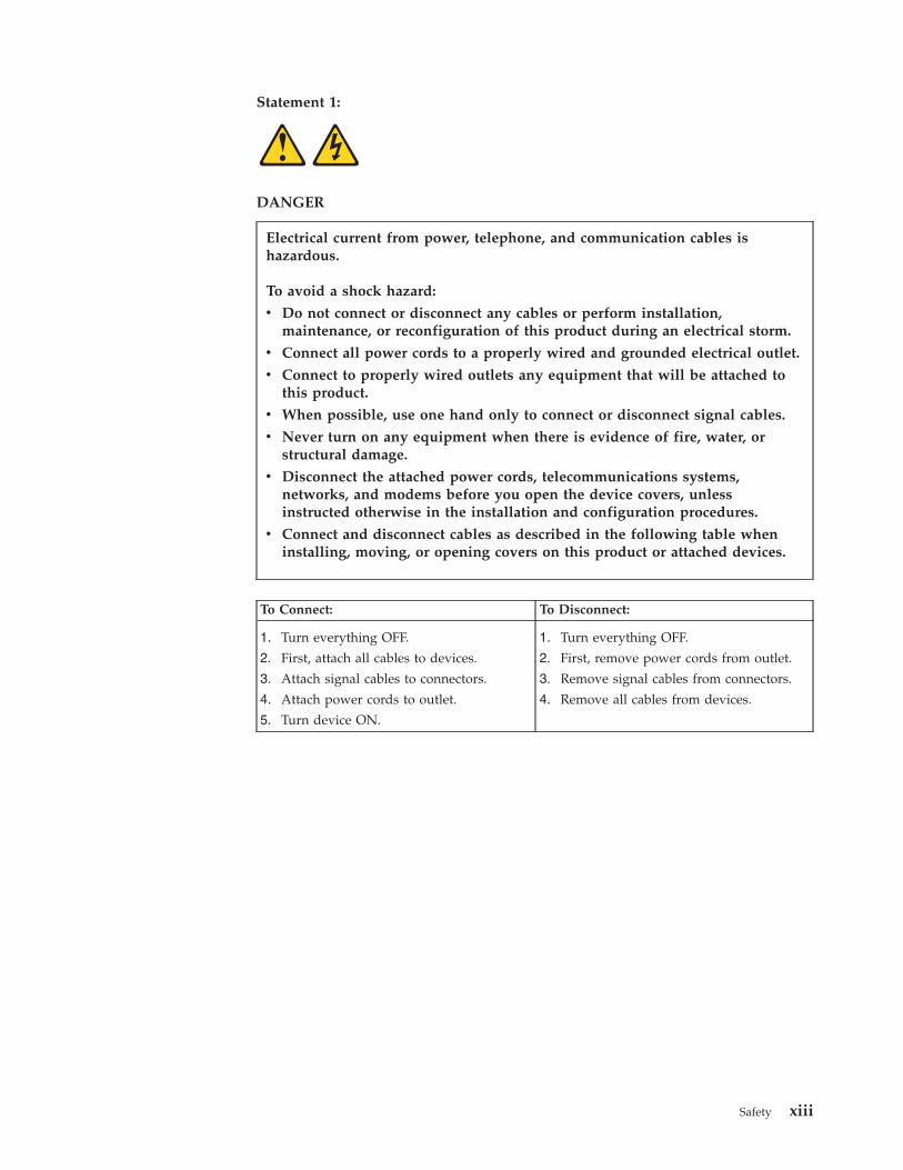
Statement 1:
DANGER
Electrical current from power, telephone, and communication cables is
hazardous.
To avoid a shock hazard:
v Do not connect or disconnect any cables or perform installation,
maintenance, or reconfiguration of this product during an electrical storm.
v Connect all power cords to a properly wired and grounded electrical outlet.
v Connect to properly wired outlets any equipment that will be attached to
this product.
v When possible, use one hand only to connect or disconnect signal cables.
v Never turn on any equipment when there is evidence of fire, water, or
structural damage.
v Disconnect the attached power cords, telecommunications systems,
networks, and modems before you open the device covers, unless
instructed otherwise in the installation and configuration procedures.
v Connect and disconnect cables as described in the following table when
installing, moving, or opening covers on this product or attached devices.
To Connect: To Disconnect:
1. Turn everything OFF.
2. First, attach all cables to devices.
3. Attach signal cables to connectors.
4. Attach power cords to outlet.
5. Turn device ON.
1. Turn everything OFF.
2. First, remove power cords from outlet.
3. Remove signal cables from connectors.
4. Remove all cables from devices.
Safety xiii
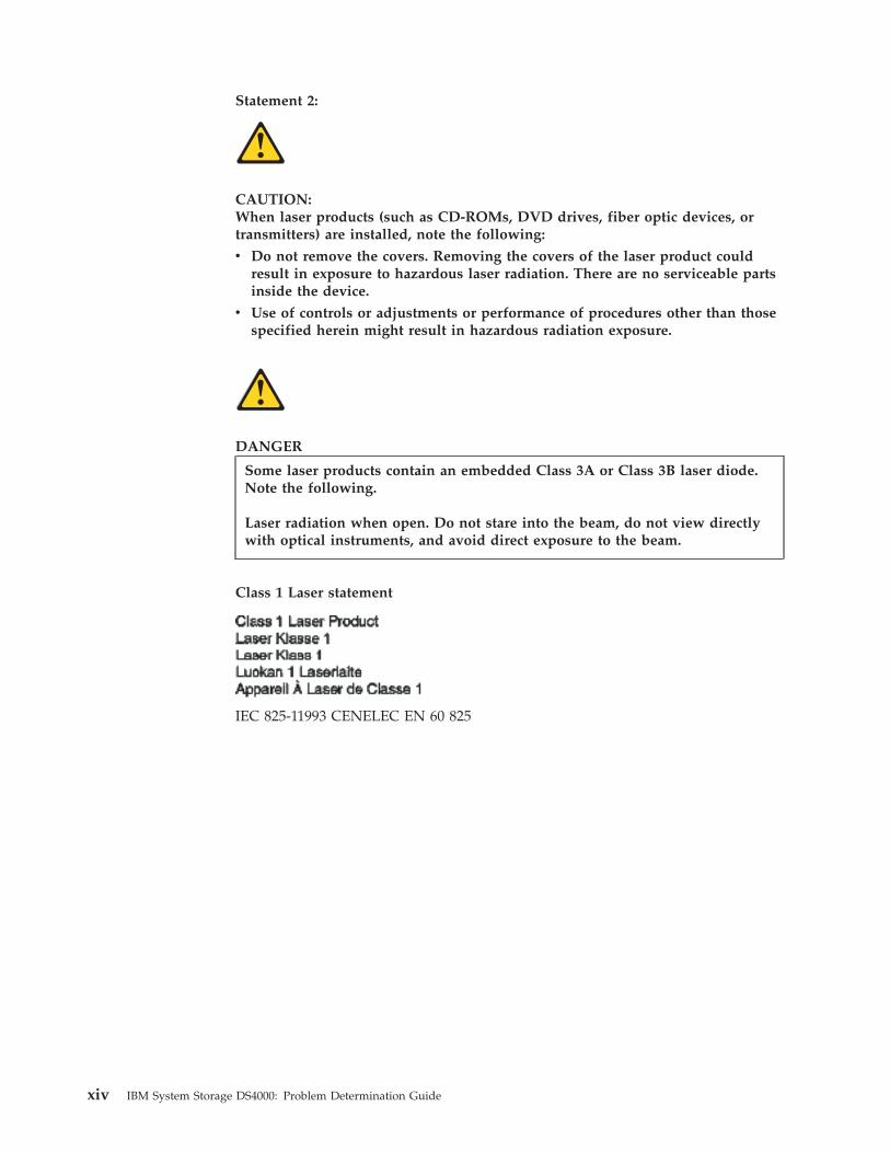
Statement 2:
CAUTION:
When laser products (such as CD-ROMs, DVD drives, fiber optic devices, or
transmitters) are installed, note the following:
v Do not remove the covers. Removing the covers of the laser product could
result in exposure to hazardous laser radiation. There are no serviceable parts
inside the device.
v Use of controls or adjustments or performance of procedures other than those
specified herein might result in hazardous radiation exposure.
DANGER
Some laser products contain an embedded Class 3A or Class 3B laser diode.
Note the following.
Laser radiation when open. Do not stare into the beam, do not view directly
with optical instruments, and avoid direct exposure to the beam.
Class 1 Laser statement
IEC 825-11993 CENELEC EN 60 825
xiv IBM System Storage DS4000: Problem Determination Guide

Statement 3:
≥ 18 kg (39.7 lb) ≥ 32 kg (70.5 lb) ≥ 55 kg (121.2 lb)
CAUTION:
Use safe practices when lifting.
Statement 4:
CAUTION:
The power control button on the device and the power switch on the power
supply do not turn off the electrical current supplied to the device. The device
also might have more than one power cord. To remove all electrical current from
the device, ensure that all power cords are disconnected from the power source.
1
2
Safety xv
Statement 5:
CAUTION:
Never remove the cover on a power supply or any part that has the following
label attached.
Hazardous voltage, current, and energy levels are present inside any component
that has this label attached. There are no serviceable parts inside these
components. If you suspect a problem with one of these parts, contact a service
technician.
Safety information
Before you service an IBM computer, you must be familiar with the following
safety information.
General safety
Follow these rules to ensure general safety:
v Observe good housekeeping in the area of the machines during and after
maintenance.
v When lifting any heavy object:
1. Ensure that you can stand safely without slipping.
2. Distribute the weight of the object equally between your feet.
3. Use a slow lifting force. Never move suddenly or twist when you attempt to
lift.
4. Lift by standing or by pushing up with your leg muscles; this action removes
the strain from the muscles in your back. Do not attempt to lift any objects that
weigh more than 16 kg (35 lb) or objects that you think are too heavy for you.
v Do not perform any action that causes hazards to the customer, or that makes
the equipment unsafe.
v Before you start the machine, ensure that other service representatives and the
customer’s personnel are not in a hazardous position.
v Place removed covers and other parts in a safe place, away from all personnel,
while you are servicing the machine.
v Keep your tool case away from walk areas so that other people will not trip over
it.
v Do not wear loose clothing that can be trapped in the moving parts of a
machine. Ensure that your sleeves are fastened or rolled up above your elbows.
If your hair is long, fasten it.
v Insert the ends of your necktie or scarf inside clothing or fasten it with a
nonconductive clip, approximately 8 centimeters (3 in.) from the end.
xvi IBM System Storage DS4000: Problem Determination Guide
v Do not wear jewelry, chains, metal-frame eyeglasses, or metal fasteners for your
clothing. Remember: Metal objects are good electrical conductors.
v Wear safety glasses when you are doing any of the following: hammering,
drilling soldering, cutting wire, attaching springs, using solvents, or working in
any other conditions that might be hazardous to your eyes.
v After service, reinstall all safety shields, guards, labels, and ground wires.
Replace any safety device that is worn or defective.
v Reinstall all covers correctly before returning the machine to the customer.
Grounding requirements
Electrical grounding of the computer is required for operator safety and correct
system function. Proper grounding of the electrical outlet can be verified by a
certified electrician.
Electrical safety
Important
Use only approved tools and test equipment. Some hand tools have handles that are covered with a soft material
that does not insulate you when working with live electrical currents.
Many customers have, near their equipment, rubber floor mats that contain small conductive fibers to decrease
electrostatic discharges. Do not use this type of mat to protect yourself from electrical shock.
Observe the following rules when working on electrical equipment.
v Find the room emergency power off (EPO) switch, disconnecting switch, or
electrical outlet. If an electrical accident occurs, you can then operate the switch
or unplug the power cord quickly.
v Do not work alone under hazardous conditions or near equipment that has
hazardous voltages.
v Disconnect all power before doing any of the following tasks:
– Performing a mechanical inspection
– Working near power supplies
– Removing or installing main unitsv Before you start to work on the machine, unplug the power cord. If you cannot
unplug it, ask the customer to power-off the wall box that supplies power to the
machine and to lock the wall box in the off position.
v If you need to work on a machine that has exposed electrical circuits, observe the
following precautions:
– Ensure that another person, familiar with the power-off controls, is near you.
Remember: Another person must be there to switch off the power, if
necessary.
– Use only one hand when working with powered-on electrical equipment;
keep the other hand in your pocket or behind your back.
Remember: There must be a complete circuit to cause electrical shock. By
observing the previous rule, you might prevent a current from passing
through your body.
– When using testers, set the controls correctly and use the approved probe
leads and accessories for that tester.
– Stand on suitable rubber mats (obtained locally, if necessary) to insulate you
from grounds such as metal floor strips and machine frames.
Safety xvii
Observe the special safety precautions when you work with very high voltages;
these instructions are in the safety sections of maintenance information. Use
extreme care when measuring high voltages.
v Regularly inspect and maintain your electrical hand tools for safe operational
condition.
v Do not use worn or broken tools and testers.
v Never assume that power has been disconnected from a circuit. First, check that it
has been powered-off.
v Always look carefully for possible hazards in your work area. Examples of these
hazards are moist floors, nongrounded power extension cables, power surges,
and missing safety grounds.
v Do not touch live electrical circuits with the reflective surface of a plastic dental
mirror. The surface is conductive and can cause personal injury and machine
damage.
v Do not service the following parts (or similar units) with the power on when they
are removed from their normal operating places in a machine. This practice
ensures correct grounding of the units.
– Power supply units
– Pumps
– Blowers and fans
– Motor generatorsv If an electrical accident occurs:
– Use caution; do not become a victim yourself.
– Switch off power.
– Send another person to get medical aid.
Handling ESD-sensitive devices
Any computer part that contains transistors or integrated circuits (ICs) should be
considered sensitive to electrostatic discharge (ESD). ESD damage can occur when
there is a difference in charge between objects. Protect against ESD damage by
equalizing the charge so that the machine, the part, the work mat, and the person
that is handling the part are all at the same charge.
Notes:
1. Use product-specific ESD procedures when they exceed the requirements noted
here.
2. Make sure that the ESD protective devices that you use have been certified
(ISO 9000) as fully effective.
Use the following precautions when handling ESD-sensitive parts:
v Keep the parts in protective packages until they are inserted into the product.
v Avoid contact with other people.
v Wear a grounded wrist strap against your skin to eliminate static on your body.
v Prevent the part from touching your clothing. Most clothing is insulative and
retains a charge even when you are wearing a wrist strap.
v Select a grounding system, such as those listed below, to provide protection that
meets the specific service requirement.
Note: The use of a grounding system is desirable but not required to protect
against ESD damage.
xviii IBM System Storage DS4000: Problem Determination Guide
– Attach the ESD ground clip to any frame ground, ground braid, or green-wire
ground.
– Use an ESD common ground or reference point when working on a
double-insulated or battery-operated system. You can use coax or
connector-outside shells on these systems.
– Use the round ground-prong of the ac plug on ac-operated computers.v Use the black side of a grounded work mat to provide a static-free work surface.
The mat is especially useful when handling ESD-sensitive devices.
Safety inspection procedure
Use this safety inspection procedure to identify potentially unsafe conditions on a
product. Each machine, as it was designed and built, had required safety items
installed to protect users and service personnel from injury. This procedure
addresses only those items. However, good judgment should be used to identify
any potential safety hazards due to attachment of non-IBM features or options not
covered by this inspection procedure.
If any unsafe conditions are present, you must determine how serious the apparent
hazard could be and whether you can continue without first correcting the
problem.
Consider these conditions and the safety hazards they present:
v Electrical hazards, especially primary power (primary voltage on the frame can
cause serious or fatal electrical shock).
v Explosive hazards, such as a damaged cathode ray tube (CRT) face or bulging
capacitor
v Mechanical hazards, such as loose or missing hardware
Complete the following checks with the power off, and with the power cord
disconnected.
1. Check the exterior covers for damage (loose, broken, or sharp edges).
2. Check the power cord for the following conditions:
a. A third-wire ground connector in good condition. Use a meter to measure
third-wire ground continuity for 0.1 ohm or less between the external
ground pin and frame ground.
b. The power cord should be the appropriate type as specified in the parts
listings.
c. Insulation must not be frayed or worn.3. Remove the cover.
4. Check for any obvious non-IBM alterations. Use good judgment as to the safety
of any non-IBM alterations.
5. Check the inside the unit for any obvious unsafe conditions, such as metal
filings, contamination, water or other liquids, or signs of fire or smoke damage.
6. Check for worn, frayed, or pinched cables.
7. Check that the power supply cover fasteners (screws or rivets) have not been
removed or tampered with.
Safety xix

xx IBM System Storage DS4000: Problem Determination Guide
About this document
This document provides information about problem determination for the IBM
System Storage DS4000 product line. Use this document for the following tasks:
v Diagnose and troubleshoot system faults
v Configure and service hardware
v Determine system specifications
v Interpret system data
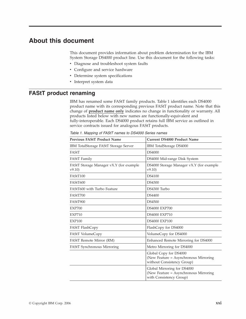
FAStT product renaming
IBM has renamed some FAStT family products. Table 1 identifies each DS4000
product name with its corresponding previous FAStT product name. Note that this
change of product name only indicates no change in functionality or warranty. All
products listed below with new names are functionally-equivalent and
fully-interoperable. Each DS4000 product retains full IBM service as outlined in
service contracts issued for analogous FAStT products.
Table 1. Mapping of FAStT names to DS4000 Series names
Previous FAStT Product Name Current DS4000 Product Name
IBM TotalStorage FAStT Storage Server IBM TotalStorage DS4000
FAStT DS4000
FAStT Family DS4000 Mid-range Disk System
FAStT Storage Manager vX.Y (for example
v9.10)
DS4000 Storage Manager vX.Y (for example
v9.10)
FAStT100 DS4100
FAStT600 DS4300
FAStT600 with Turbo Feature DS4300 Turbo
FAStT700 DS4400
FAStT900 DS4500
EXP700 DS4000 EXP700
EXP710 DS4000 EXP710
EXP100 DS4000 EXP100
FAStT FlashCopy FlashCopy for DS4000
FAStT VolumeCopy VolumeCopy for DS4000
FAStT Remote Mirror (RM) Enhanced Remote Mirroring for DS4000
FAStT Synchronous Mirroring Metro Mirroring for DS4000
Global Copy for DS4000(New Feature = Asynchronous Mirroring
without Consistency Group)
Global Mirroring for DS4000(New Feature = Asynchronous Mirroring
with Consistency Group)
© Copyright IBM Corp. 2006 xxi

Who should read this document
This document is intended for system operators and service technicians who have
extensive knowledge of fibre channel and network technology.
How this document is organized
The IBM System Storage DS4000 Problem Determination Guide contains information
that you can use to isolate and solve problems that might occur in your fibre
channel configurations. It provides problem determination and resolution
information for the issues most commonly encountered with IBM fibre channel
devices and configurations.
Attention: Beginning with the first edition of this document, the IBM System
Storage DS4000 Hardware Maintenance Manual and the IBM System Storage DS4000
Problem Determination Guide are published as separate documents. In addition, the
hardware maintenance information for new IBM DS4000 products released with or
after this document is included in the Installation, User’s, and Maintenance Guide
for those products.
This document contains the following chapters:
Chapter 1, “About problem determination,” on page 1 provides a starting point for
the problem determination information found in this document.
Chapter 2, “Problem determination starting points,” on page 3 provides an
introduction to problem determination tools and techniques that are contained in
this document.
Chapter 3, “Problem determination maps,” on page 7 provides a series of
flowcharts that help you to isolate and resolve hardware issues.
Chapter 4, “Introduction to the QLogic SANsurfer application,” on page 35
introduces the IBM Fibre Array Storage Technology Management Suite Java
(QLogic SANsurfer).
Chapter 5, “PD hints: Common path/single path configurations,” on page 63
provides problem determination hints for common path or single path
configurations.
Chapter 6, “PD hints: RAID controller errors in the Windows 2000, Windows 2003,
or Windows NT event log,” on page 65 provides problem determination hints for
event log errors stemming from the RAID controller.
Chapter 7, “PD hints: Configuration types,” on page 79 provides the various
configuration types that can be encountered.
Chapter 8, “PD hints: Passive RAID controller,” on page 87 provides instructions
on how to isolate problems that occur in a passive RAID controller.
Chapter 9, “PD hints: Performing sendEcho tests,” on page 91 contains information
on how to perform loopback tests.
Chapter 10, “PD hints: Tool hints,” on page 95 contains information on generalized
tool usage.
xxii IBM System Storage DS4000: Problem Determination Guide
Chapter 11, “PD hints: Drive side hints and RLS diagnostics,” on page 111 contains
problem determination information for the drive or device side as well as read link
status diagnostics.
Chapter 12, “PD hints: Hubs and switches,” on page 143 provides information on
hub and switch problem determination.
Chapter 13, “PD hints: Wrap plug tests,” on page 149 provides information about
tests that you can perform with wrap plugs.
Chapter 14, “Heterogeneous configurations,” on page 153 contains information
about heterogeneous configurations.
Chapter 15, “Using the IBM Fast!UTIL utility,” on page 157 provides detailed
configuration information for advanced users who want to customize the
configuration of the IBM fibre-channel PCI adapter (FRU 01K7354), the IBM
DS4000 host adapter (FRU 09N7292), and the IBM DS4000 FC2-133 Adapter (FRU
24P0962).
Chapter 16, “Frequently asked questions about the DS4000 Storage Manager,” on
page 163 contains a list of the questions about the DS4000 Storage Manager that
are most frequently asked.
Chapter 17, “pSeries supplemental problem determination information,” on page
173 discusses fibre channel-specific problems and information that might be
necessary to resolve them.
Appendix A, “Additional DS4000 documentation,” on page 181 lists documentation
for all of the DS4000 products.
Appendix B, “Accessibility,” on page 191 provides information about DS4000
Storage Manager alternate keyboard navigation.
Notices used in this document
This document can contain the following notices that are designed to highlight key
information:
v Note: These notices provide important tips, guidance, or advice.
v Important: These notices provide information that might help you avoid
inconvenient or problem situations.
v Attention: These notices indicate possible damage to programs, devices, or data.
An attention notice is placed just before the instruction or situation in which
damage could occur.
v Caution: These statements indicate situations that can be potentially hazardous
to you. A caution statement is placed just before the description of a potentially
hazardous procedure step or situation.
v Danger: These statements indicate situations that can be potentially lethal or
extremely hazardous to you. A danger statement is placed just before the
description of a potentially lethal or extremely hazardous procedure step or
situation.
About this document xxiii
Getting information, help, and service
If you need help, service, or technical assistance or just want more information
about IBM products, you will find a wide variety of sources available from IBM to
assist you. This section contains information about where to go for additional
information about IBM and IBM products, what to do if you experience a problem
with your IBM Eserver xSeries or IntelliStation system, and whom to call for
service, if it is necessary.
Before you call
Before you call, make sure that you have taken these steps to try to solve the
problem yourself:
v Check all cables to make sure that they are connected.
v Check the power switches to make sure that the system is turned on.
v Use the troubleshooting information in your system documentation and use the
diagnostic tools that come with your system.
v Check for technical information, hints, tips, and new device drivers at the
following Web site:
www.ibm.com/servers/storage/support/disk/
v Use an IBM discussion forum on the IBM Web site to ask questions.
You can solve many problems without outside assistance by following the
troubleshooting procedures that IBM provides in the online help or in the
documents that are provided with your system and software. The information that
comes with your system also describes the diagnostic tests that you can perform.
Most xSeries and IntelliStation systems, operating systems, and programs come
with information that contains troubleshooting procedures and explanations of
error messages and error codes. If you suspect a software problem, see the
information for the operating system or program.
Using the documentation
Information about the xSeries or IntelliStation system and preinstalled software, if
any, is available in the documents that come with your system. This includes
printed documents, online documents, readme files, and help files. See the
troubleshooting information in your system documentation for instructions on how
to use the diagnostic programs. The troubleshooting information or the diagnostic
programs might tell you that you need additional or updated device drivers or
other software.
Web sites
IBM maintains pages on the World Wide Web where you can get the latest
technical information and download device drivers and updates.
v For DS4000 information, go to the following Web site:
www.ibm.com/servers/storage/support/disk/
The support page has many sources of information and ways for you to solve
problems, including:
– Diagnosing problems using the IBM Online Assistant
– Downloading the latest device drivers and updates for your products
– Viewing frequently asked questions (FAQ)
– Viewing hints and tips to help you solve problems
– Participating in IBM discussion forums
xxiv IBM System Storage DS4000: Problem Determination Guide
– Setting up e-mail notification of technical updates about your productsv You can order publications through the IBM Publications Ordering System at the
following web site:
www.elink.ibmlink.ibm.com/public/applications/publications/cgibin/pbi.cgi/
v For the latest information about IBM xSeries products, services, and support, go
to the following Web site:
www.ibm.com/eserver/xseries/
v For the latest information about IBM pSeries products, services, and support, go
to the following Web site:
www.ibm.com/eserver/pseries/
v For the latest information about the IBM IntelliStation information, go to the
following Web site:
www-132.ibm.com/content/home/store_IBMPublicUSA/en_US/IntelliStation_workstations.html
v For the latest information about operating system and HBA support, clustering
support, SAN fabric support, and Storage Manager feature support, see the
TotalStorage DS4000 Interoperability Matrix at the following Web site:
www.ibm.com/servers/storage/disk/ds4000/interop-matrix.html
Software service and support
Through IBM Support Line, for a fee you can get telephone assistance with usage,
configuration, and software problems with xSeries servers, IntelliStation
workstations, and appliances. For information about which products are supported
by Support Line in your country or region, go to the following Web site:
www.ibm.com/services/sl/products/
For more information about the IBM Support Line and other IBM services, go to
the following Web sites:
v www.ibm.com/services/
v www.ibm.com/planetwide/
Hardware service and support
You can receive hardware service through IBM Integrated Technology Services or
through your IBM reseller, if your reseller is authorized by IBM to provide
warranty service. Go to the following Web site for support telephone numbers:
www.ibm.com/planetwide/
In the U.S. and Canada, hardware service and support is available 24 hours a day,
7 days a week. In the U.K., these services are available Monday through Friday,
from 9 a.m. to 6 p.m.
Fire suppression systems
A fire suppression system is the responsibility of the customer. The customer’s own
insurance underwriter, local fire marshal, or a local building inspector, or both,
should be consulted in selecting a fire suppression system that provides the correct
level of coverage and protection. IBM designs and manufactures equipment to
internal and external standards that require certain environments for reliable
operation. Because IBM does not test any equipment for compatibility with fire
suppression systems, IBM does not make compatibility claims of any kind nor
does IBM provide recommendations on fire suppression systems.
About this document xxv

How to send your comments
Your feedback is important in helping us to provide the most accurate and
high-quality information. If you have comments or suggestions for improving this
publication, you can send us comments electronically by using these addresses:
v Internet: [email protected]
v IBMLink from U.S.A.: STARPUBS at SJEVM5
v IBMLink from Canada: STARPUBS at TORIBM
v IBM Mail Exchange: USIB3WD at IBMMAIL
You can also mail your comments by using the Reader Comment Form in the back
of this manual or direct your mail to:
International Business Machines Corporation
Information Development
Dept. GZW
9000 South Rita Road
Tucson, AZ 85744–0001
U.S.A.
xxvi IBM System Storage DS4000: Problem Determination Guide
Chapter 1. About problem determination
The procedures in this document are designed to help you isolate problems. They
are written with the assumption that you have model-specific training on all
computers, or that you are familiar with the computers, functions, terminology,
and service-related information provided in this document and the appropriate
IBM server hardware maintenance manual.
This guide provides problem determination and resolution information for the
issues most commonly encountered with IBM fibre channel devices and
configurations. This manual contains useful component information, such as
specifications, replacement and installation procedures, and basic symptom lists.
Note: For information about how to use and troubleshoot problems with the FC
6228 2 Gigabit fibre channel adapter in IBM Eserver pSeries AIX hosts, see
Fibre Channel Planning and Integration: User’s Guide and Service Information,
SC23-4329.
Where to start
To use this document correctly, begin by identifying a particular problem area from
the lists provided in “Starting points for problem determination” on page 5. The
starting points direct you to the related PD maps, which provide graphical
directions to help you identify and resolve problems. The problem determination
maps in Chapter 2 might also refer you to other PD maps or to other chapters or
appendices in this document. When you complete tasks that are required by the
PD maps, it might be helpful to see the component information that is provided in
the IBM System Storage DS4000 Hardware Maintenance Manual.
Related documents
For information about managed hubs and switches that might be in your network,
see the following publications:
v IBM 3534 SAN Fibre Channel Managed Hub Installation and Service Guide,
SY27-7616
v IBM SAN Fibre Channel Switch 2109 Model S08 Installation and Service Guide,
SC26-7350
v IBM SAN Fibre Channel Switch 2109 Model S16 Installation and Service Guide,
SC26-7352
This installation and service information can also be found at the following Web
site:
www.ibm.com/storage/ibmsan/products.htm
For information about major event log data, see the IBM System Storage DS4000
Event Log Specification, GC26-7852-00.
© Copyright IBM Corp. 2006 1
Product updates
Important
In order to keep your system up to date with the latest firmware and other
product updates, use the information below to register and use the My
support Web site.
Download the latest versions of the DS4000 Storage Manager host software,
DS4000 storage server controller firmware, DS4000 drive expansion enclosure ESM
firmware, and drive firmware at the time of the initial installation and when
product updates become available.
To be notified of important product updates, you must first register at the IBM
Support and Download Web site:
www-1.ibm.com/servers/storage/support/disk/index.html
In the Additional Support section of the Web page, click My support. On the next
page, if you have not already done so, register to use the site by clicking Register
now.
Perform the following steps to receive product updates:
1. After you have registered, type your user ID and password to log into the site.
The My support page opens.
2. Click Add products. A pull-down menu displays.
3. In the pull-down menu, select Storage. Another pull-down menu displays.
4. In the new pull-down menu, and in the subsequent pull-down menus that
display, select the following topics:
v Computer Storage
v Disk Storage Systems
v TotalStorage DS4000 Midrange Disk Systems & FAStT Stor Srvrs
Note: During this process a check list displays. Do not check any of the items
in the check list until you complete the selections in the pull-down
menus.
5. When you finish selecting the menu topics, place a check in the box for the
machine type of your DS4000 series product, as well as any other attached
DS4000 series product(s) for which you would like to receive information, then
click Add products. The My Support page opens again.
6. On the My Support page, click the Edit profile tab, then click Subscribe to
email. A pull-down menu displays.
7. In the pull-down menu, select Storage. A check list displays.
8. Place a check in each of the following boxes:
a. Please send these documents by weekly email
b. Downloads and drivers
c. Flashes
d. Any other topics that you may be interested in
Then, click Update.
9. Click Sign out to log out of My Support.
2 IBM System Storage DS4000: Problem Determination Guide
Chapter 2. Problem determination starting points
This chapter contains information to help you perform the tasks required when
you follow PD procedures. Review this information before you attempt to isolate
and resolve fibre channel problems. This chapter also provides summaries of the
tools that might be useful in following the PD procedures provided in Chapter 3,
“Problem determination maps,” on page 7.
Note: The PD maps in this document are not to be used in order of appearance.
Always begin working with the PD maps from the starting points provided in this
chapter (see “Starting points for problem determination” on page 5). Do not
use a PD map unless you are directed there from a particular symptom or
problem area in one of the lists of starting points, or from another PD map.
Problem determination tools
The PD maps in Chapter 3, “Problem determination maps,” on page 7 rely on
numerous tools and diagnostic programs to isolate and fix the problems. You use
the following tools when performing the tasks directed by the PD maps.
Loopback Data Test
Host bus adapters type 2200 and above support loopback testing, which
can be run from the QLogic SANsurfer diagnostics. (For more information
on the SANsurfer application, see Chapter 4, “Introduction to the QLogic
SANsurfer application,” on page 35.)
Wrap plugs
Wrap plugs are required to run the Loopback test at the host bus adapter
or at the end of cables. There are two types of wrap plugs: SC and LC. SC
wrap plugs are used for the larger connector cables. A coupler is provided
for each respective form-factor to connect the wrap plugs to cables. The
part numbers for the wrap plugs are:
v SC: 75G2725 (wrap and coupler kit)
v LC
– 24P0950 (wrap connector and coupler kit)
– 11P3847 (wrap connector packaged with DS4400 Storage Server)
– 05N6766 (coupler packaged with DS4400 Storage Server)
Note: Many illustrations in this document depict the LC wrap plug.
Substitute the LC wrap plug for the FAStT 200 (3254) and the FAStT
500 (3557).
QLogic SANsurfer Management Application
The SANsurfer application is network-capable and can connect to and
configure remote systems. With the SANsurfer application, you can
perform loopback and read/write buffer tests to help isolate problems.
See Chapter 4, “Introduction to the QLogic SANsurfer application,” on
page 35 for further details on the SANsurfer application.
IBM DS4000 Storage Manager
© Copyright IBM Corp. 2006 3
The DS4000 Storage Manager provides the capability to monitor events
and manage storage in a heterogeneous environment. These diagnostic and
storage management capabilities fulfill the requirements of a true SAN, but
also increase complexity and the potential for problems. Chapter 14,
“Heterogeneous configurations,” on page 153 shows examples of
heterogeneous configurations and the associated profiles from the DS4000
Storage Manager. These examples can help you identify improperly
configured storage by comparing the customer’s profile with those
supplied (assuming similar configurations).
Event Monitoring has also been implemented in these versions of DS4000
Storage Manager. The Event Monitor handles notification functions (e-mail
and SNMP traps) and monitors storage subsystems whenever the
Enterprise Management window is not open. The Event Monitor is a
separate program bundled with the DS4000 Storage Manager client
software; it is a background task that runs independently of the Enterprise
Management window.
The DS4000 Storage Manager implements controller runtime diagnostics.
The DS4000 Storage Manager also implements Read Link Status (RLS),
which enables diagnostics to aid in troubleshooting drive-side problems.
DS4000 Storage Manager establishes a time stamped ″baseline″ value for
drive error counts and keeps track of drive error events. The end user
receives deltas over time, as well as trends.
Considerations before starting PD maps
Because a wide variety of hardware and software combinations are possible, use
the following information to assist you in problem determination. Before you use
the PD maps, perform the following actions:
v Verify any recent hardware changes.
v Verify any recent software changes.
v Verify that the BIOS is at the latest level. See “File updates” on page 5 and
specific server hardware maintenance manuals for details about this procedure.
v Verify that device drivers are at the latest levels. See the device driver
installation information in the installation guide for your device.
v Verify that the configuration matches the hardware.
v Verify that the SANsurfer application is the most current version. For more
information, see Chapter 4, “Introduction to the QLogic SANsurfer application,”
on page 35.
As you go through the problem determination procedures, consider the following
questions:
v Do diagnostics fail?
v Is the failure repeatable?
v Has this configuration ever worked?
v If this configuration has been working, what changes were made prior to it
failing?
v Is this the original reported failure? If not, try to isolate failures using the lists of
indications (see “General symptoms” on page 5, “Specific problem areas” on
page 5, and “PD maps and diagrams” on page 6).
4 IBM System Storage DS4000: Problem Determination Guide

Important
To eliminate confusion, systems are considered identical only if the following are exactly
identical for each system:
v Machine type and model
v BIOS level
v Adapters and attachments (in same locations)
v Address jumpers, terminators, and cabling
v Software versions and levels
Comparing the configuration and software setup between working and non-working
systems will often resolve problems.
File updates
You can download diagnostic, BIOS flash, and device driver files from the
following Web site:
www.ibm.com/servers/eserver/serverproven/compat/us/
Starting points for problem determination
The lists of indications contained in this section provide you with entry points to
the problem determination maps found in this chapter. (Links to useful appendix
materials are also provided.) Use the following lists of problem areas as a guide for
determining which PD maps will be most helpful.
General symptoms
v RAID controller passive
If you determine that a RAID controller is passive, go to “RAID Controller
Passive PD map” on page 9.
v Failed or moved cluster resource
If you determine that a cluster resource failed or has been moved, go to “Cluster
Resource PD map” on page 10.
v Start long delay
If the host experiences a long delay at startup (more than 10 minutes), go to
“Start Delay PD map” on page 11.
v Systems Management or DS4000 Storage Manager performance problems
If you discover a problem through the Systems Management or Storage
Management tools, go to “Systems Management PD map” on page 12.
Specific problem areas
v DS4000 Storage Manager
See “Systems Management PD map” on page 12.
See also Chapter 16, “Frequently asked questions about the DS4000 Storage
Manager,” on page 163.
v Port configuration (Linux)
See “Linux Port Configuration PD map 1” on page 24.
v Microsoft Windows 2000, Windows 2003, or Windows NT Event Log
See Chapter 6, “PD hints: RAID controller errors in the Windows 2000, Windows
2003, or Windows NT event log,” on page 65.
Chapter 2. Problem determination starting points 5

v Fibre channel problems on the pSeries AIX system
SeeChapter 17, “pSeries supplemental problem determination information,” on
page 173.
v Indicator lights on devices
See “Indicator lights and problem indications” on page 114.
v Major Event Log (MEL)
See the IBM System Storage DS4000 Event Log Specification (GC26-7852-00).
v Control panel or SCSI adapters
See the driver installation information in the appropriate hardware chapter of
the installation guide for your device.
v Managed hub or switch logs
See Chapter 12, “PD hints: Hubs and switches,” on page 143.
v Cluster Administrator
v IBM pSeries servers with 6228 and 6239 HBAs
“pSeries PD map” on page 26
PD maps and diagrams
v Configuration Type Determination
To determine whether your configuration is type 1 or type 2, go to
“Configuration Type PD map” on page 8.
To break larger configurations into manageable units for debugging, see
Chapter 7, “PD hints: Configuration types,” on page 79.
v Hub or Switch PD
If you determine that a problem exists within a hub or switch, go to
“Hub/Switch PD map 2” on page 14.
v Fibre Path PD
If you determine that a problem exists within the Fibre Path, go to “Fibre Path
PD map 1” on page 16.
v Device PD
If you determine that a problem exists within a device, go to “Device PD map 1”
on page 22.
6 IBM System Storage DS4000: Problem Determination Guide
Chapter 3. Problem determination maps
This chapter contains a series of PD maps that guide you through problem
isolation and resolution. Before you use any of the following PD maps, you should
have reviewed the information in Chapter 2, “Problem determination starting
points,” on page 3.
The PD maps in this chapter are not to be used in order of appearance. Always
begin working with the PD maps from the starting points provided in the previous chapter
(see “Starting points for problem determination” on page 5). Do not use a PD map
unless you are directed there from a particular symptom or problem area in one of
the lists of starting points, or from another PD map.
© Copyright IBM Corp. 2006 7
Configuration Type PD map
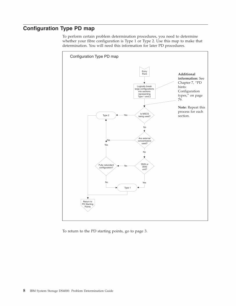
To perform certain problem determination procedures, you need to determine
whether your fibre configuration is Type 1 or Type 2. Use this map to make that
determination. You will need this information for later PD procedures.
Configuration Type PD map
EntryPoint
Logically breaklarge configurations
into sectionsrepresentingType 1 and 2
Is MSCSbeing used?
Are externalconcentrators
used?
Fully redundantconfiguration?
Yes
Yes
Type 2
Type 1
Return toPD Starting
Points
3526 or3542unit?
Yes
Yes
No
No
No
No
Additional
information: See
Chapter 7, “PD
hints:
Configuration
types,” on page
79.
Note: Repeat this
process for each
section.
To return to the PD starting points, go to page 3.
8 IBM System Storage DS4000: Problem Determination Guide

RAID Controller Passive PD map
From: “General symptoms” on page 5; “Cluster Resource PD map” on page 10.
ControllerPassive?
Return to PD entry No
NT event 18?
Yes
Controller Passive PD map
More nodessharing RAIDController?
Save date/timeand SRB info
Yes
Yes
Find earliestevent 18
No
Is SRBx0D, 0E, 0F?
Yes
EntryPoint
Any yellow lightson concentrator/
minihubs?
No
No
Yes
ToFibre PathPD map 2
Additional information:
See Chapter 8, “PD hints:
Passive RAID controller,”
on page 87.
Additional information:
Use MEL information to
find the approximate fail
time in the Windows®
event log. See the System
Storage DS4000 Event Log
Specification.
Additional information:
See Chapter 6, “PD hints:
RAID controller errors in
the Windows 2000,
Windows 2003, or
Windows NT event log,”
on page 65.
Additional information:
See Chapter 6, “PD hints:
RAID controller errors in
the Windows 2000,
Windows 2003, or
Windows NT event log,”
on page 65.
To see Fibre Path PD map 2, go to “Fibre Path PD map 2” on page 17.
Chapter 3. Problem determination maps 9

Cluster Resource PD map
From: “General symptoms” on page 5.
Was ClusterResourceMoved?
CheckRAID
Controllers
ControllerPassive?
ClusterResourceFailed?
No
Indicator Lights,cluster log
Yes
Debug one failureat a time
Check SM,
Check SM,
Indicator Lights,cluster log
No
ToControllerPassivePD map
Yes
EntryPoint
Cluster Resource PD map
Wasresourcemoved by
administrator?Problem solved Yes
No
Yes
Additional
information: This
situation can occur
only from multiple
concurrent fails (if
not moved by the
administrator).
Additional
information: This
situation can occur
only from multiple
concurrent fails.
To see the RAID Controller Passive PD map, go to “RAID Controller Passive PD
map” on page 9.
10 IBM System Storage DS4000: Problem Determination Guide

Start Delay PD map
From: “General symptoms” on page 5.
Boot-up Delay PD map
EntryPoint
Is the start-upscreen hangingfor long time?
Unplug HBA(s)Fibre connection
at device(concentrator,controller, etc.)
Did systemcome upquickly?
Not a fibreproblem-Look at
applications
Replug fibrecables and
restart
Have you beenhere
already?
No
No
Yes
Yes
No
Return toPD Starting
Points
Done
Yes
Insert wrap plugat the cable end.
data test
Yes
Yes
HBAType
2100?
ToFibre PathPD map 2
ReplaceHBA
Loopbacktest passes
ReplaceCable
No
Restart system anduse FAStT MSJ
Insert wrap plugat HBA run
loopback data test
to enable HBA(s)
Loopbacktest
Passes?
Replugcables
Yes No
No
OperatingSystem
Symptoms
Windows NT Blue screen – no dot crawl activity
Windows 2000 Windows 2000 Starting Upprogress bar
LinuxStartup sequence frozen: waitingfor LIP to complete, kernel panic,no log-in dialog
Start FAStT MSJand run loopback
See “Start delay”
on page 97 and
Chapter 6, “PD
hints: RAID
controller errors
in the Windows
2000, Windows
2003, or Windows
NT event log,” on
page 65.
See “Linux port
configuration” on
page 106.
Additional
information: See
Chapter 4,
“Introduction to
the QLogic
SANsurfer
application,” on
page 35.
To return to the options for PD entry, go to page 3.
To see Fibre Path PD map 2, go to “Fibre Path PD map 2” on page 17.
Chapter 3. Problem determination maps 11

Systems Management PD map
From: “General symptoms” on page 5.
EntryPoint
Using SYS MGMTalert info, look at
SM/RecoveryGuru
Is theproblemfixed?
Call IBM Support
No
Done Yes
Systems Management
Additional
information: See
Chapter 16,
“Frequently asked
questions about the
DS4000 Storage
Manager,” on page
163.
12 IBM System Storage DS4000: Problem Determination Guide
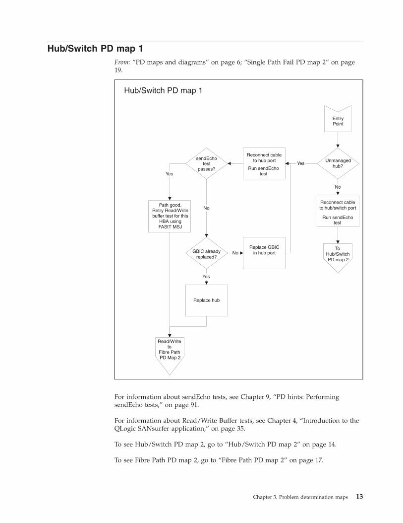
Hub/Switch PD map 1
From: “PD maps and diagrams” on page 6; “Single Path Fail PD map 2” on page
19.
EntryPoint
Unmanagedhub?
Reconnect cableto hub port
Run sendEchotest
YessendEcho
testpasses?
Path good.Retry Read/Writebuffer test for this
HBA usingFAStT MSJ
Yes
Replace GBICin hub port
Read/Writeto
Fibre PathPD Map 2
GBIC alreadyreplaced?
No
No
Replace hub
Yes
Reconnect cableto hub/switch port
Run sendEcho
No
Hub/Switch PD map 1
ToHub/SwitchPD map 2
test
For information about sendEcho tests, see Chapter 9, “PD hints: Performing
sendEcho tests,” on page 91.
For information about Read/Write Buffer tests, see Chapter 4, “Introduction to the
QLogic SANsurfer application,” on page 35.
To see Hub/Switch PD map 2, go to “Hub/Switch PD map 2” on page 14.
To see Fibre Path PD map 2, go to “Fibre Path PD map 2” on page 17.
Chapter 3. Problem determination maps 13
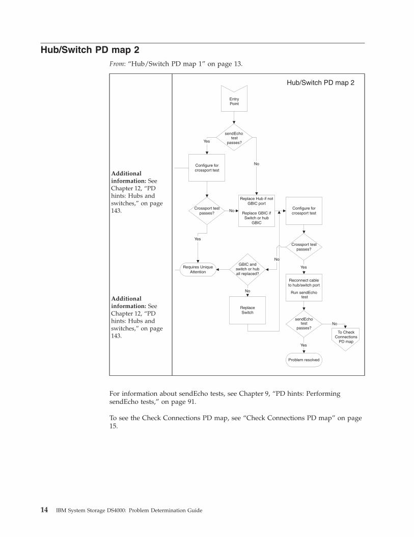
Hub/Switch PD map 2
From: “Hub/Switch PD map 1” on page 13.
Additional
information: See
Chapter 12, “PD
hints: Hubs and
switches,” on page
143.
Additional
information: See
Chapter 12, “PD
hints: Hubs and
switches,” on page
143.
Configure forcrossport test
Crossport testpasses?
testpasses?
Replace Hub if notGBIC port
Replace GBIC ifSwitch or hub
GBIC
No
Reconnect cableto hub/switch port
Run sendEcho
sendEchotest
passes?
Configure forcrossport test
Crossport test
test
passes?
Yes
Problem resolved
Yes
GBIC andswitch or huball replaced?
No
ReplaceSwitch
No
Requires UniqueAttention
Yes
No
Yes
To CheckConnections
PD map
No
EntryPoint
Hub/Switch PD map 2
sendEcho
For information about sendEcho tests, see Chapter 9, “PD hints: Performing
sendEcho tests,” on page 91.
To see the Check Connections PD map, see “Check Connections PD map” on page
15.
14 IBM System Storage DS4000: Problem Determination Guide
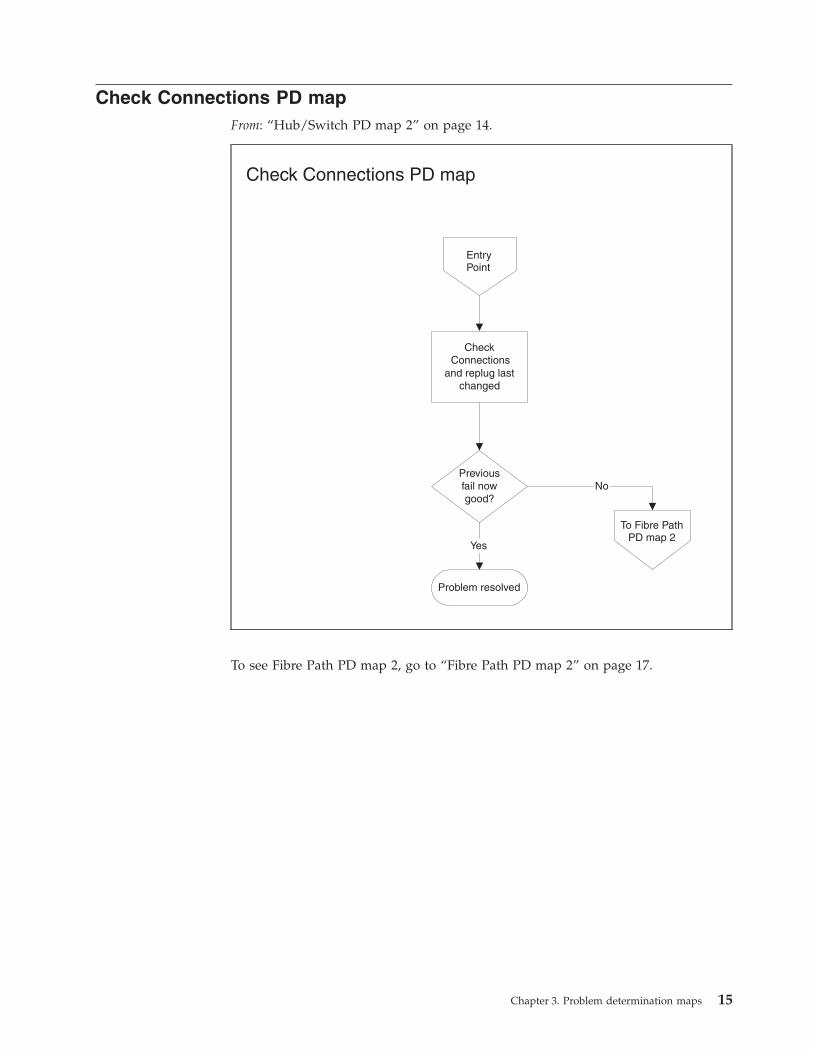
Check Connections PD map
From: “Hub/Switch PD map 2” on page 14.
CheckConnections
and replug lastchanged
Previousfail nowgood?
Problem resolved
Yes
Check Connections PD map
No
To Fibre PathPD map 2
EntryPoint
To see Fibre Path PD map 2, go to “Fibre Path PD map 2” on page 17.
Chapter 3. Problem determination maps 15
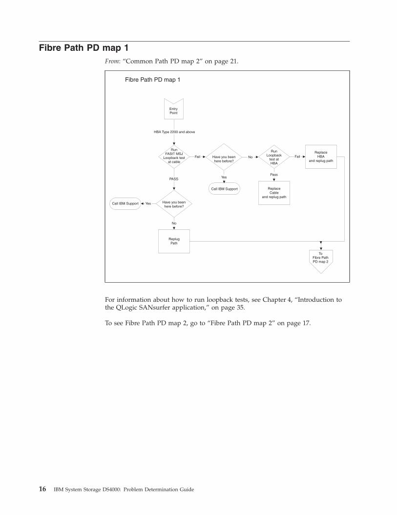
Fibre Path PD map 1
From: “Common Path PD map 2” on page 21.
Call IBM Suppor
Fibre Path PD map 1
RunLoopback
test atHBA
ReplaceCable
and replug path
Pass
ReplaceHBA
and replug pathFailFail Have you been
here before?
Call IBM Support
YesPASS
HBA Type 2200 and above
Have you beenhere before?
t Yes
ReplugPath
No
EntryPoint
ToFibre PathPD map 2
No
RunFAStT MSJ
Loopback testat cable
For information about how to run loopback tests, see Chapter 4, “Introduction to
the QLogic SANsurfer application,” on page 35.
To see Fibre Path PD map 2, go to “Fibre Path PD map 2” on page 17.
16 IBM System Storage DS4000: Problem Determination Guide
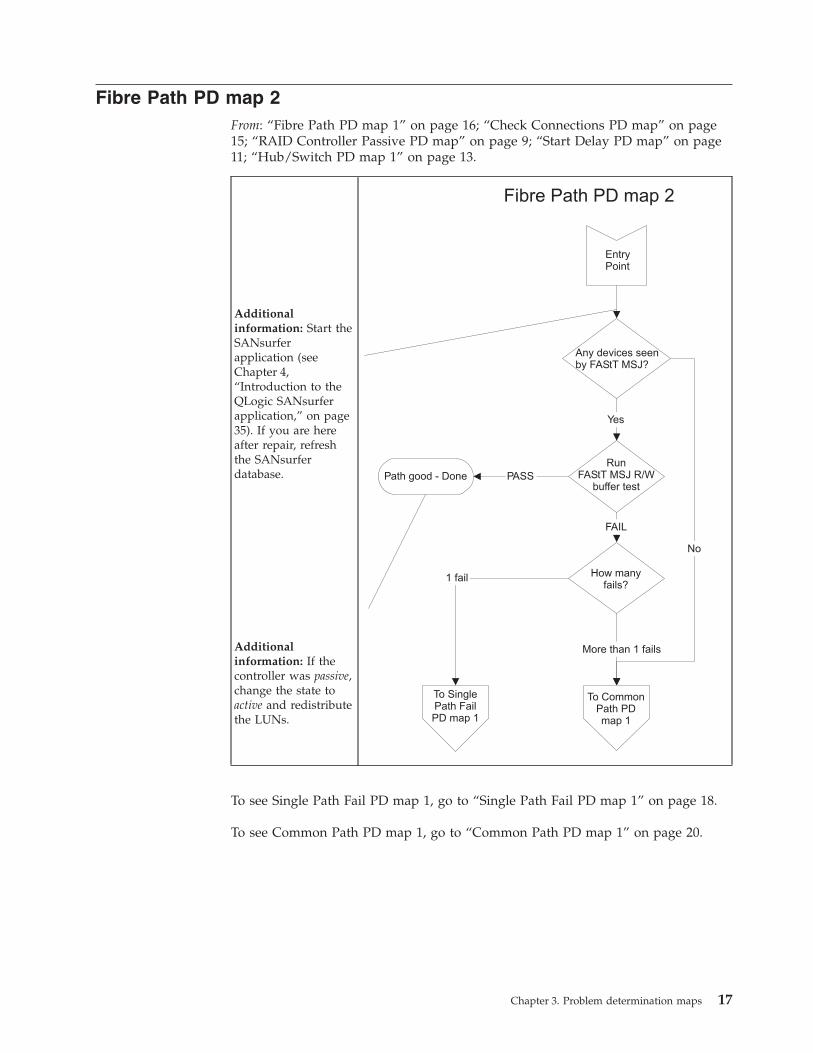
Fibre Path PD map 2
From: “Fibre Path PD map 1” on page 16; “Check Connections PD map” on page
15; “RAID Controller Passive PD map” on page 9; “Start Delay PD map” on page
11; “Hub/Switch PD map 1” on page 13.
Additional
information: Start the
SANsurfer
application (see
Chapter 4,
“Introduction to the
QLogic SANsurfer
application,” on page
35). If you are here
after repair, refresh
the SANsurfer
database.
Additional
information: If the
controller was passive,
change the state to
active and redistribute
the LUNs.
RunFAStT MSJ R/W
buffer testPath good - Done PASS
How manyfails?
FAIL
1 fail
More than 1 fails
To SinglePath FailPD map 1
Any devices seenby FAStT MSJ?
Yes
No
EntryPoint
To CommonPath PDmap 1
Fibre Path PD map 2
To see Single Path Fail PD map 1, go to “Single Path Fail PD map 1” on page 18.
To see Common Path PD map 1, go to “Common Path PD map 1” on page 20.
Chapter 3. Problem determination maps 17

Single Path Fail PD map 1
From: “Fibre Path PD map 2” on page 17.
Single Path Fail PD map 1
Disconnect cablefrom failed path at
controller end
Insert wrap plug atcontroller end
Run sendEchotest
sendEcho
DiagnosticsPass?
testpasses?
ReplaceMIA if 3526
Replace GBICif other
HaveMIA/GBIC
already beenreplaced?
Replace minihubor controller
Have minihuband controller
been replaced?No
No
Yes
Yes
Yes
NoNo
Call IBM Support
To SinglePath Fail
PD map 2
EntryPoint
Run ControllerRun Time
Diagnostic for bothcontrollers
Yes
Additional
information: See
Chapter 13, “PD
hints: Wrap plug
tests,” on page 149.
Additional
information: See
Chapter 9, “PD hints:
Performing sendEcho
tests,” on page 91.
Additional
information: See
“Controller
diagnostics” on page
105.
To see Single Path Fail PD map 2, go to “Single Path Fail PD map 2” on page 19.
18 IBM System Storage DS4000: Problem Determination Guide

Single Path Fail PD map 2
From: “Single Path Fail PD map 1” on page 18.
Remove wrap plug.Replace cable at
Controller.Remove cable atconcentrator end.
Insert wrap plugon cable end
Run sendEchotest
Echopasses?
Replace cable
Cable alreadyreplaced?
No
ToHub/SwitchPD map 1
Yes
Yes
No
Call IBM Support
Single Path Fail PD map 2
EntryPoint
send
Additional
information: See
Chapter 13, “PD
hints: Wrap plug
tests,” on page 149.
Additional
information: See
Chapter 9, “PD
hints: Performing
sendEcho tests,” on
page 91.
To see Hub/Switch PD map 1, go to “Hub/Switch PD map 1” on page 13.
Chapter 3. Problem determination maps 19
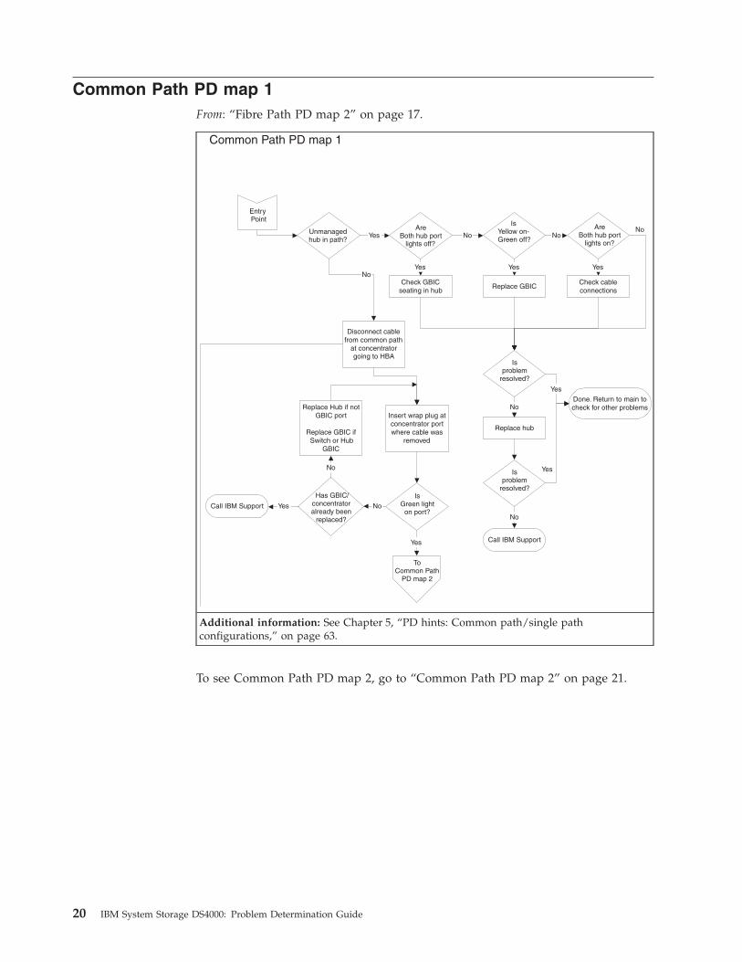
Common Path PD map 1
From: “Fibre Path PD map 2” on page 17.
Common Path PD map 1
Disconnect cablefrom common path
at concentratorgoing to HBA
Insert wrap plug atconcentrator portwhere cable was
removed
IsGreen light
on port?
Has GBIC/concentratoralready been
replaced?
NoYes
No
Call IBM Support
Replace Hub if notGBIC port
Replace GBIC ifSwitch or Hub
GBIC
Unmanagedhub in path?
No
AreBoth hub port
lights off?Yes
IsYellow on-Green off?
No
Check GBICseating in hub
Yes
Replace GBIC
Yes
lights on?No
Check cableconnections
Yes
No
Isproblem
resolved?
Done. Return to main tocheck for other problems
Yes
Call IBM Support
Replace hub
No
No
EntryPoint
ToCommon Path
PD map 2
Yes
AreBoth hub port
Isproblem
resolved?
Yes
Additional information: See Chapter 5, “PD hints: Common path/single path
configurations,” on page 63.
To see Common Path PD map 2, go to “Common Path PD map 2” on page 21.
20 IBM System Storage DS4000: Problem Determination Guide

Common Path PD map 2
From: “Common Path PD map 1” on page 20.
HBA type2100?
Configure for crossporttest using cable
disconnected at HBAend and wrap plug on
cable
Yes
No
Crossport testpasses?
Replace cable-return to main
Replace 2100-return to main
No
YesToFibre PathPD map 1
EntryPoint
Common Path PD map 2
Additional
information: See
Chapter 12, “PD
hints: Hubs and
switches,” on page
143.
See
To see Fibre Path PD map 1, go to “Fibre Path PD map 1” on page 16.
Chapter 3. Problem determination maps 21

Device PD map 1
From: “PD maps and diagrams” on page 6.
EntryPoint
Device side of 3526controller unit?
Check SM anduse Recovery
Guruto determine
actions
Problemresolved?
Done
Call IBMsupport
Yes
No
Yes
Errorindicators on device
side units?
No
Device PD map 1
No
Yes
ToDevice
PD map 2
Additional
information: See
“Drive side hints”
on page 111 in
Chapter 11, “PD
hints: Drive side
hints and RLS
diagnostics.”
To see Device PD map 2, go to “Device PD map 2” on page 23.
22 IBM System Storage DS4000: Problem Determination Guide
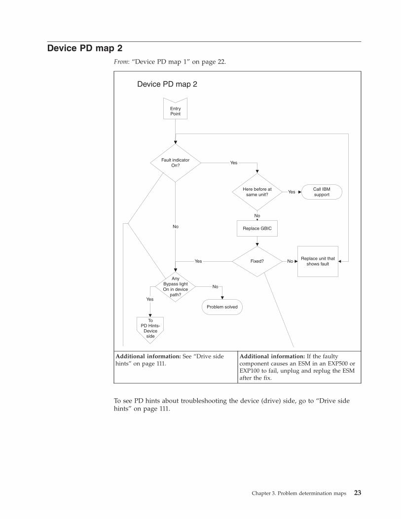
Device PD map 2
From: “Device PD map 1” on page 22.
AnyBypass lightOn in device
path?
Fault indicatorOn?
Yes
Replace GBIC
ToPD Hints-
Deviceside
Yes
Problem solved
Here before atsame unit?
Replace unit thatshows fault
Call IBMsupport
Yes
Fixed? No
No
No
Yes
No
EntryPoint
Device PD map 2
Additional information: See “Drive side
hints” on page 111.
Additional information: If the faulty
component causes an ESM in an EXP500 or
EXP100 to fail, unplug and replug the ESM
after the fix.
To see PD hints about troubleshooting the device (drive) side, go to “Drive side
hints” on page 111.
Chapter 3. Problem determination maps 23
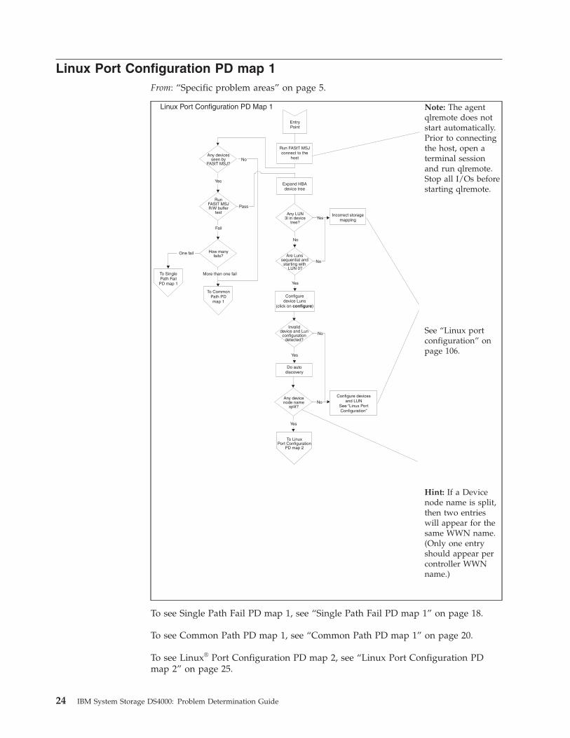
Linux Port Configuration PD map 1
From: “Specific problem areas” on page 5.
Run FAStT MSJconnect to the
host
Configuredevice Luns
(click on )configure
Are Lunssequential and
starting withLUN 0?
No
Yes
Do autodiscovery
Yes
Invaliddevice and Lunconfiguration
detected?
No
Fail
RunFAStT MSJR/W buffer
testPass
Yes
Any devicesseen by
FAStT MSJ?No
Yes
Any devicenode name
split?
To LinuxPort Configuration
PD map 2
No
Configure devicesand LUN
See “Linux PortConfiguration”
More than one fail
One fail How manyfails?
To SinglePath Fail
PD map 1
To CommonPath PDmap 1
EntryPoint
Expand HBAdevice tree
No
Any LUN3l in device
tree?Yes
Incorrect storagemapping
Linux Port Configuration PD Map 1
Note: The agent
qlremote does not
start automatically.
Prior to connecting
the host, open a
terminal session
and run qlremote.
Stop all I/Os before
starting qlremote.
See “Linux port
configuration” on
page 106.
Hint: If a Device
node name is split,
then two entries
will appear for the
same WWN name.
(Only one entry
should appear per
controller WWN
name.)
To see Single Path Fail PD map 1, see “Single Path Fail PD map 1” on page 18.
To see Common Path PD map 1, see “Common Path PD map 1” on page 20.
To see Linux® Port Configuration PD map 2, see “Linux Port Configuration PD
map 2” on page 25.
24 IBM System Storage DS4000: Problem Determination Guide

Linux Port Configuration PD map 2
From: “Linux Port Configuration PD map 1” on page 24
EntryPoint
Use Storage Managerto map thefor Linux and reconfigure
the ports using FAStT MSJ
device/LUNs
Right-click onsplit controller node
name and selectdevice information
Linux Port Configuration PD Map 2
Hint: Right-click
the Host icon in
the HBA Tree and
select Adapter
Persistent
Configuration
Data ... The
Adapter(s) WWNN
is displayed.
Record this
information as it
will be required by
the DS4000 Storage
Manager to map
your storage to the
Linux OS.
Additional
information: See
“Linux port
configuration” on
page 106.
To see Single Path Fail PD map 1, see “Single Path Fail PD map 1” on page 18.
Chapter 3. Problem determination maps 25
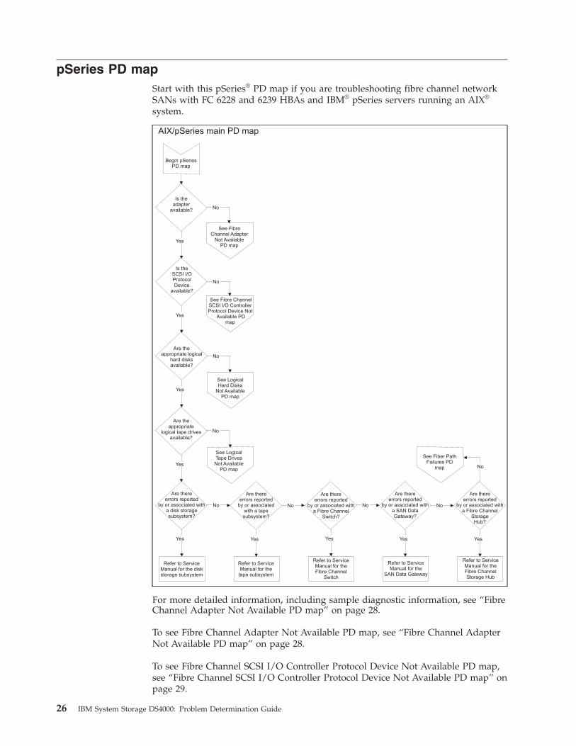
pSeries PD map
Start with this pSeries® PD map if you are troubleshooting fibre channel network
SANs with FC 6228 and 6239 HBAs and IBM® pSeries servers running an AIX®
system.
AIX/pSeries main PD map
No
Are thereerrors reported
by or associated witha SAN DataGateway?
Yes
Refer to ServiceManual for the
SAN Data Gateway
No
Yes
Are thereerrors reported
by or associated witha Fibre Channel
StorageHub?
Yes
Refer to ServiceManual for theFibre ChannelStorage Hub
See FibreChannel Adapter
Not AvailablePD map
Yes
Is theSCSI I/OProtocolDevice
available?
No
Yes
No
Yes
No
Is theadapter
available?
See Fibre ChannelSCSI I/O ControllerProtocol Device Not
Available PDmap
Yes
No
Are theappropriate logical
hard disksavailable?
See LogicalHard Disks
Not AvailablePD map
Are theappropriate
logical tape drivesavailable?
See LogicalTape DrivesNot Available
PD map
Yes
No
Are thereerrors reported
by or associated witha disk storagesubsystem?
Refer to ServiceManual for the diskstorage subsystem
Are thereerrors reported
by or associated witha Fibre Channel
Switch?
Refer to ServiceManual for theFibre Channel
Switch
No
Are thereerrors reported
by or associatedwith a tapesubsystem?
Yes
Refer to ServiceManual for the
tape subsystem
See Fiber PathFailures PD
map
Begin pSeriesPD map
No
For more detailed information, including sample diagnostic information, see “Fibre
Channel Adapter Not Available PD map” on page 28.
To see Fibre Channel Adapter Not Available PD map, see “Fibre Channel Adapter
Not Available PD map” on page 28.
To see Fibre Channel SCSI I/O Controller Protocol Device Not Available PD map,
see “Fibre Channel SCSI I/O Controller Protocol Device Not Available PD map” on
page 29.
26 IBM System Storage DS4000: Problem Determination Guide

To see Logical Hard Disks Not Available PD map, see “Logical Hard Disks Not
Available PD map” on page 30.
To see Logical Hard Tapes Not Available PD map, see “Logical Tape Drives Not
Available PD map” on page 31.
To see Fiber Path Failures PD map, see “Fiber Path Failures PD map 1” on page 32.
Chapter 3. Problem determination maps 27

Fibre Channel Adapter Not Available PD map
From: “pSeries PD map” on page 26
0020 Fibre Channel Adapter Not Available PD map
No
Did thediagnostics run
on the FibreChannel Adapter
fail?
Yes
Yes
No
Is theadapterdefined?
Yes
No
Are the devicedrivers properly
installed?
ReinstallDevice Drivers
Yes
No
Is theadapter defined
or availablenow?
Done
No
Install GigabitFibre ChannelPCI Adapter
Is the FibreChannel adapterinstalled in theAIX system?
Yes
Replace GigabitFibre Channel
Adapter
Call IBMSupport
Continuefrom pSeries
PD map
For more detailed information, including sample diagnostic information, see “Fibre
Channel Adapter Not Available PD map.”
28 IBM System Storage DS4000: Problem Determination Guide
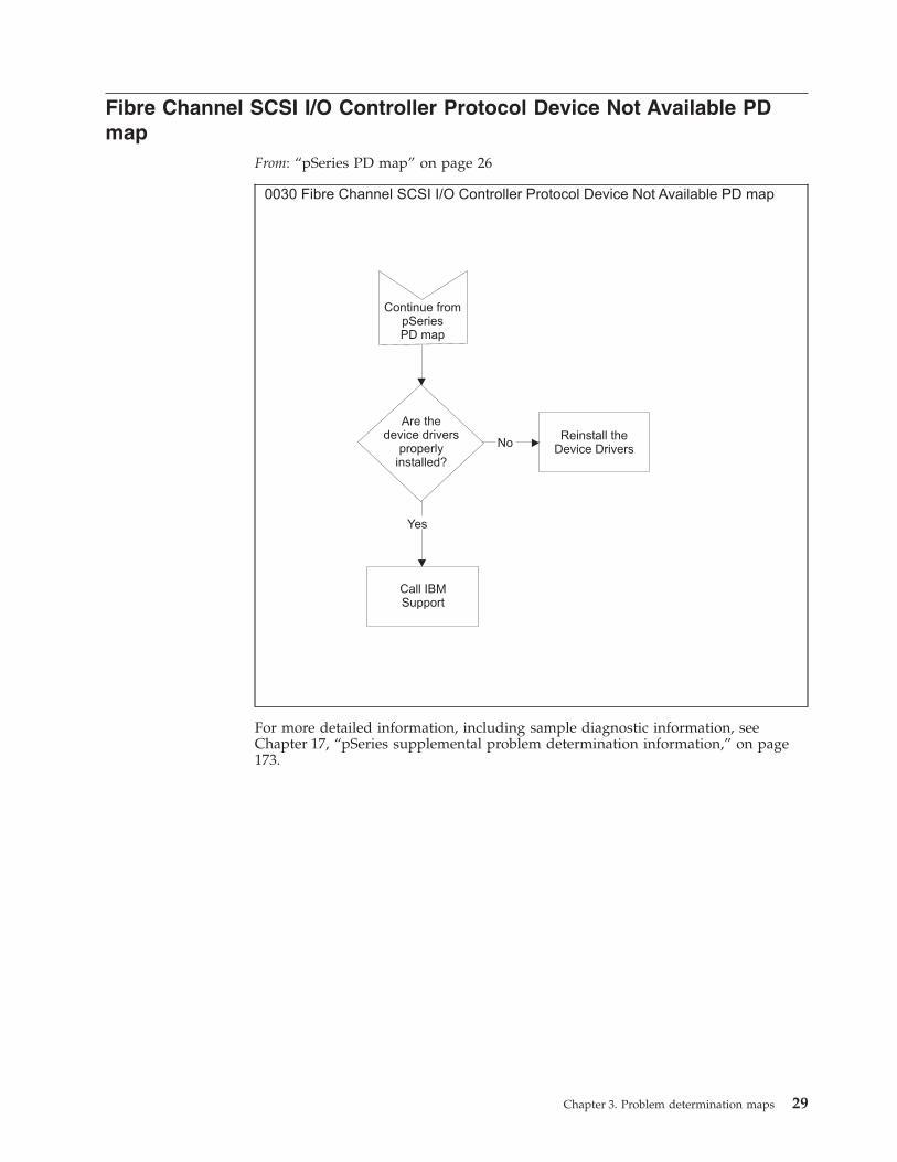
Fibre Channel SCSI I/O Controller Protocol Device Not Available PD
map
From: “pSeries PD map” on page 26
0030 Fibre Channel SCSI I/O Controller Protocol Device Not Available PD map
Yes
No
Are thedevice drivers
properlyinstalled?
Reinstall theDevice Drivers
Call IBMSupport
Continue frompSeriesPD map
For more detailed information, including sample diagnostic information, see
Chapter 17, “pSeries supplemental problem determination information,” on page
173.
Chapter 3. Problem determination maps 29
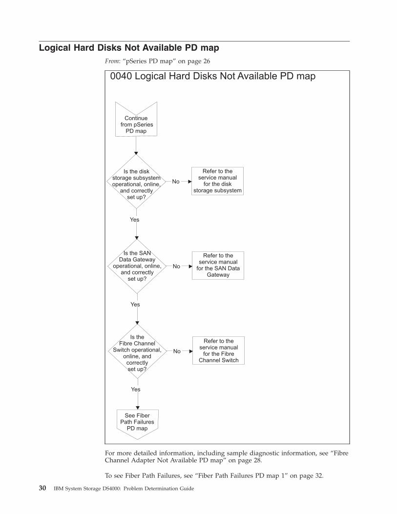
Logical Hard Disks Not Available PD map
From: “pSeries PD map” on page 26
0040 Logical Hard Disks Not Available PD map
Yes
No
Yes
No
Yes
No
Is the diskstorage subsystemoperational, online,
and correctlyset up?
Refer to theservice manual
for the diskstorage subsystem
Is the SANData Gateway
operational, online,and correctly
set up?
Refer to theservice manual
for the SAN DataGateway
Is theFibre Channel
Switch operational,online, and
correctlyset up?
Refer to theservice manual
for the FibreChannel Switch
See FiberPath Failures
PD map
Continuefrom pSeries
PD map
For more detailed information, including sample diagnostic information, see “Fibre
Channel Adapter Not Available PD map” on page 28.
To see Fiber Path Failures, see “Fiber Path Failures PD map 1” on page 32.
30 IBM System Storage DS4000: Problem Determination Guide
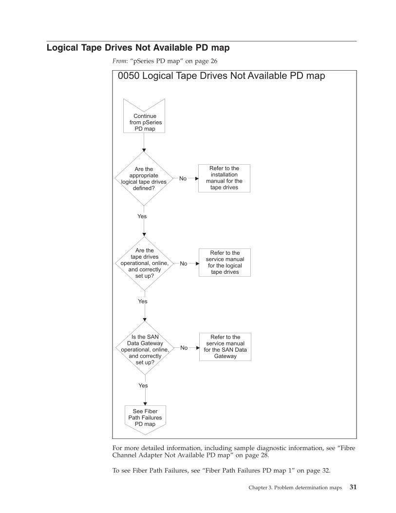
Logical Tape Drives Not Available PD map
From: “pSeries PD map” on page 26
0050 Logical Tape Drives Not Available PD map
Yes
No
Yes
No
Yes
No
Are theappropriate
logical tape drivesdefined?
Refer to theinstallation
manual for thetape drives
Are thetape drives
operational, online,and correctly
set up?
Refer to theservice manualfor the logicaltape drives
Is the SANData Gateway
operational, online,and correctly
set up?
Refer to theservice manual
for the SAN DataGateway
See FiberPath Failures
PD map
Continuefrom pSeries
PD map
For more detailed information, including sample diagnostic information, see “Fibre
Channel Adapter Not Available PD map” on page 28.
To see Fiber Path Failures, see “Fiber Path Failures PD map 1” on page 32.
Chapter 3. Problem determination maps 31
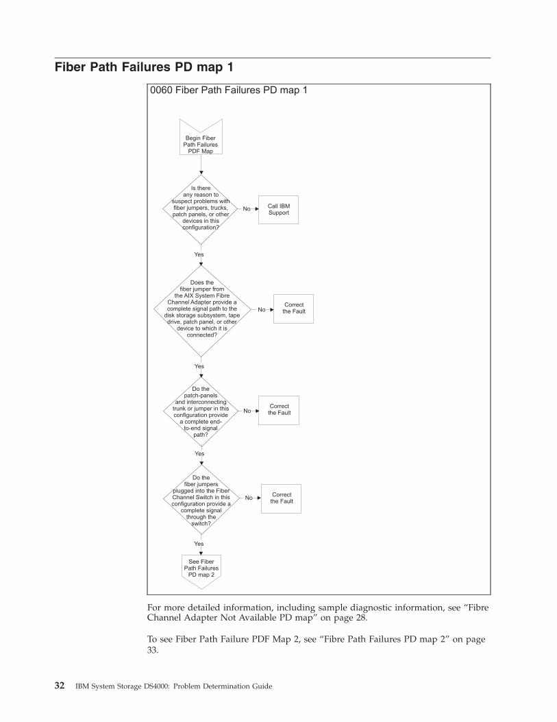
Fiber Path Failures PD map 1
0060 Fiber Path Failures PD map 1
Begin FiberPath Failures
PDF Map
Yes
Yes
Yes
Yes
Correctthe Fault
Correctthe Fault
Correctthe Fault
Does thefiber jumper from
the AIX System FibreChannel Adapter provide acomplete signal path to the
disk storage subsystem, tapedrive, patch panel, or other
device to which it isconnected?
Do thepatch-panels
and interconnectingtrunk or jumper in thisconfiguration provide
a complete end-to-end signal
path?
Do thefiber jumpers
plugged into the FiberChannel Switch in thisconfiguration provide a
complete signalthrough the
switch?
No
No
No
No
Is thereany reason to
suspect problems withfiber jumpers, trucks,patch panels, or other
devices in thisconfiguration?
Call IBMSupport
See FiberPath Failures
PD map 2
For more detailed information, including sample diagnostic information, see “Fibre
Channel Adapter Not Available PD map” on page 28.
To see Fiber Path Failure PDF Map 2, see “Fibre Path Failures PD map 2” on page
33.
32 IBM System Storage DS4000: Problem Determination Guide
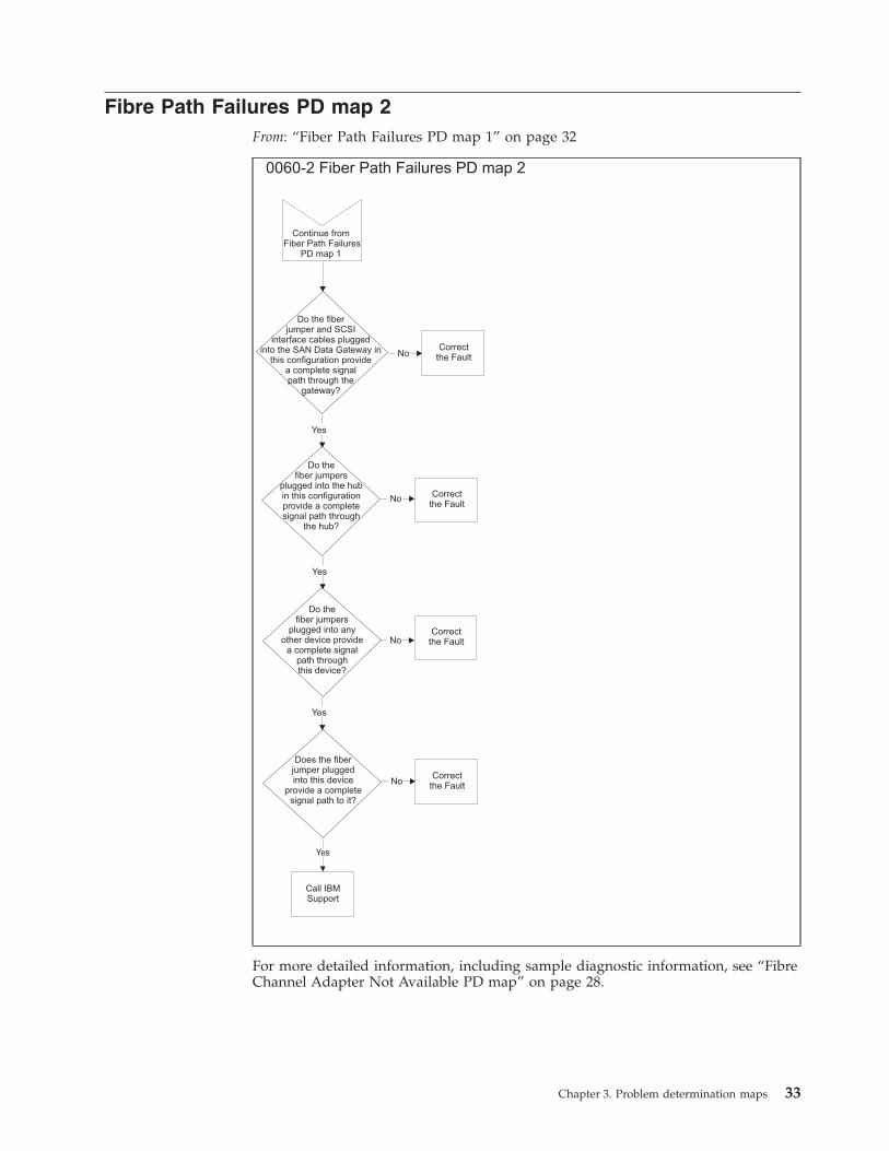
Fibre Path Failures PD map 2
From: “Fiber Path Failures PD map 1” on page 32
0060-2 Fiber Path Failures PD map 2
Yes
Yes
Yes
Correctthe Fault
Correctthe Fault
Correctthe Fault
Correctthe Fault
Do the fiberjumper and SCSI
interface cables pluggedinto the SAN Data Gateway in
this configuration providea complete signalpath through the
gateway?
Do thefiber jumpers
plugged into the hubin this configurationprovide a completesignal path through
the hub?
Do thefiber jumpers
plugged into anyother device provide
a complete signalpath throughthis device?
No
No
No
No
Continue fromFiber Path Failures
PD map 1
Does the fiberjumper pluggedinto this device
provide a completesignal path to it?
Yes
Call IBMSupport
For more detailed information, including sample diagnostic information, see “Fibre
Channel Adapter Not Available PD map” on page 28.
Chapter 3. Problem determination maps 33

34 IBM System Storage DS4000: Problem Determination Guide

Chapter 4. Introduction to the QLogic SANsurfer application
This chapter introduces the QLogic SANsurfer application and includes
background information on SAN environments and an overview of the functions
of the SANsurfer application. The SANsurfer application replaces the IBM FAStT
Management Suite Java™ (FAStT MSJ) application.
Note: See the SANsurfer online help for more detailed information about the
SANsurfer application. The SANsurfer downloads are found under each
specific DS4000 product.
SAN environment
In a typical Storage Area Network (SAN) environment, a system might be
equipped with multiple host bus adapters (HBAs) that control devices on the local
loop or on the fabric.
In addition, a single device can be visible to and controlled by more than one
HBA. An example of this is dual-path devices used in a primary/failover setup.
In a switched or clustering setup, more than one system can access the same
device; this type of configuration enables storage sharing. Sometimes in this
scenario, a system must access certain LUNs on a device while other systems
control other LUNs on the same device.
Because SAN has scalable storage capacity, you can add new devices and targets
dynamically. After you add these new devices and targets, you need to configure
them.
A SAN can change not only through the addition of new devices, but also through
the replacement of current devices on the network. For device hot-swapping, you
sometimes need to remove old devices and insert new devices in the removed
slots.
In a complicated environment where there is hot-swapping of SAN components,
some manual configuration is required to achieve proper installation and
functionality.
SANsurfer Overview
The SANsurfer application is designed for the monitoring and configuration of a
SAN environment. This application is specifically designed for the IBM Fibre
Channel, in such an environment. Together with HBA components, storage devices
and host systems, this application helps complete a Storage Area Network.
The SANsurfer application is a network-capable (client/server) application that can
connect to and configure a remote Windows NT®, Linux, or Novell NetWare
system. The application uses ONC RPC for network communication and data
exchange. The networking capability of the application allows for centralized
management and configuration of the entire SAN.
© Copyright IBM Corp. 2006 35
SANsurfer system requirements
The SANsurfer application consists of the following two components:
v SANsurfer client interface
v Host agent
Each component has different system requirements depending on the operating
system.
SANsurfer client interface
The SANsurfer application, which is written in Java, runs on any platform that has
a compatible Java VM installed. The minimum system requirements for the
SANsurfer application to run on all platforms are as follows:
v A video adapter capable of 256 colors
v At least 128 MB of physical RAM; 256 MB is recommended. Running with less
memory might cause disk swapping, which has a negative effect on
performance.
v 64 MB of free disk space
Platform-specific requirements for the SANsurfer client interface are as follows:
v Red Hat Linux IA32
– Red Hat Linux 7.0, 7.1, 7.2, 8.0, or 9.0 (recommended configuration). AS 2.1,
3.0
– SuSe Linux SLES 8.0
– PII 233MHz (recommended minimum)v Red Hat Linux IA64
– Red Hat Linux 7.1, 7.3. AS 3.0
– Itanium® 2v Linux PPC 64
– SuSe Linux SLES 8.0
– POWER4+™ at 1.2GHz or 1.45GHz.v Microsoft® Windows IA32
– Microsoft Windows NT 4.0, W2K, XP, W2K3 (recommended configuration)
– Pentium® III processor 450 MHz or greaterv Microsoft Windows IA64
– Microsoft W2K3 (recommended configuration)
– Itanium 2v Novell NetWare
– Novell NetWare 5.x, or 6.x (recommended configuration)
– Pentium III processor 450 MHz or greater
Host agent
Host agents are platform-specific applications that reside on a host with IBM HBAs
attached. The minimum system requirements for an agent to run on all platforms
are as follows:
v An IBM SANsurfer supported device driver (see the release.txt file in the release
package for a list of supported device driver versions for each platform)
v At least 8 MB of physical RAM
36 IBM System Storage DS4000: Problem Determination Guide
v At least 2 MB of free disk space
Platform-specific requirements for the SANsurfer host agents are as follows:
v Linux x86 – Agent runs as a daemon
v Microsoft Windows NT, Windows 2000, Windows 2003, or Windows XP – Agent
runs as a Windows NT service
v Novell NetWare Installation from a Windows system
– Novell NetWare Installation Prerequisites
Note: You must be logged on as an administrator.
Be sure you have the following items before installing the SANsurfer
application for NetWare.
- On the Windows NT/2000 Client:
v Load NetWare Client software (from Novell).
v Log into the NetWare Server from the Windows NT/2000 client.
v Map a Windows drive letter to the root of the SYS Volume of the
NetWare server. Record this drive letter for later use.
v Add the NetWare host name and IP address to the Hosts file.
v Network protocols: TCP/IP transport protocol (from Microsoft)- On the NetWare Server:
v NetWare 5.X server with support pack 7 or NetWare 6.0 server with
support pack 4 or NetWare 6.5 server with support pack 2.
v Network protocols: TCP/IP and IPX/SPX transport protocols (from NIC
vendor)- Agent – Runs as an AUTOEXEC.NCF started NLM
Attention: In the file AUTOEXEC.NCF, remove REM from the front of the
following two lines:
REM RPCSTART.NCF
REM LOAD QLREMOTE.NLM
Limitations
The following is a list of limitations:
v Multiple Network Interface Cards If multiple Network Interface Cards (NICs)
are present in the system, the SANsurfer client broadcasts to the first IP address
subnet based on the binding order. Therefore, you must ensure that the NIC for
the local subnet is first in the binding order. If this is not done, the diagnostics
might not run properly, and remote connection might not occur. See the readme
file in the release package for more information.
v Host IP Addresses The SANsurfer application attempts to prevent the user from
connecting to the same host more than once. (Allowing more than one
connection causes issues with policies and wasted system resources). This adds
the requirement that all host IP addresses must resolve to a host name to allow
connection to complete.
v Local host file If DNS is not used you must edit the local host file on the
systems where you are running the SANsurfer GUI and the QLremote agent.
Add the host name to IP mapping manually. Edit the file /etc/hosts.
v Firewalls Having systems with the firewall installed can cause problems with
async alarms from the agent running on Linux to a remote machine. Problems
Chapter 4. Introduction to the QLogic SANsurfer application 37
can also occur if the GUI is running on a Linux Client communicating to a
remote machine. To circumvent this problem, type the following command at a
shell prompt:
chkconfig --list
Verify that ″ipchains and iptables″ in run levels 2, 3, 4, 5 are disabled. To disable
at a specific run level, set the following:
chkconfig --level 2 ipchains off
chkconfig --level 3 ipchains off
chkconfig --level 4 ipchains off
chkconfig --level 5 ipchains off
chkconfig --level 2 iptables off
chkconfig --level 3 iptables off
chkconfig --level 4 iptables off
chkconfig --level 5 iptables off
v HBA connected to a fabric When a DS4000 fibre channel HBA (QL2200, 2310, or
2340) is connected to the fabric (switch), Loopback test is disabled because the
adapter is in a point-to-point mode. Unplugging the cable from the fabric and
inserting a wrap plug at the end of the cable (or at the adapter) enables
loopback test.
v Online Help The SANsurfer online Web help can only be viewed in the
Netscape Communicator browser (version 4.5 or later).
v Configuration refresh When an online device fails and goes offline and a
subsequent configuration refresh occurs, the loop id for that device does not
reflect the original ID because, in effect, the device is no longer in the loop
(might show x100 or xff).
Installing the SANsurfer FC HBA Manager
Installing the SANsurfer FC HBA Manager consists of installing the SANsurfer FC
HBA Manager GUI, platform-specific agent, and help components, as appropriate.
This section provides information about the initial installation and the
uninstallation of the SANsurfer application.
Initial installation
Install the SANsurfer application, which includes the SANsurfer FC HBA Manager,
using the software from the IBM Web site or from the SANsurfer CD.
Notes:
1. Be sure to install the same version of the SANsurfer application on all systems
in the network.
2. If you have a previous version of the SANsurfer FC HBA Manager (for
example, SMS 3.0), uninstall it before installing the latest version.
Installation options
The SANsurfer FC HBA Manager supports both stand-alone and networked
configurations. Install the software that is appropriate for your configuration.
38 IBM System Storage DS4000: Problem Determination Guide
Table 2. Configuration option installation requirements
Configuration Software Requirements
Stand-alone system
This Windows 2000/Windows Server 2003
(IA32, IA64) or Red Hat/SuSE Linux (IA32)
system monitors the QLA2xxx HBAs locally.
SANsurfer FC HBA Manager GUI
This Red Hat/SuSE Linux (IA64) or Solaris
SPARC/x86 system monitors the Q LA2xxx
HBAs locally.
SANsurfer FC HBA Manager GUI and one
of the following:
v SANsurfer FC Linux Agent
v SANsurfer FC Solaris Agent
Networked system
This system monitors the QLA2xxx HBAs
locally and on remote systems running on
the same network.
SANsurfer FC HBA Manager GUI and one
of the following:
v SANsurfer FC Windows NT 4/2000/2003
Agent
v SANsurfer FC Linux Agent
v SANsurfer FC Solaris Agent
This system monitors the QLA2xxx HBAs
only on remote systems running on the
same network.
SANsurfer FC HBA Manager GUI
The QLA2xxx HBAs on this system are
monitored remotely only from other systems
on the same network.
One of the following:
v SANsurfer FC Windows NT 4/2000/2003
Agent
v SANsurfer FC Linux Agent
v SANsurfer FC Solaris Agent
v SANsurfer FC NetWare 5/6.x Agent
Installation instructions
This section is written with the assumption that you might be installing all
SANsurfer software components on any of the supported operating systems.
The SANsurfer installer is a self-extracting program that installs the SANsurfer
software, including the SANsurfer FC HBA Manager and related software.
If you will be installing the SANsurfer FC HBA Manager agent on a NetWare
server, note the following issues:
v You cannot install the SANsurfer FC HBA Manager agent directly on a NetWare
server. You must install the agent from a Windows 2000 or Windows Server 2003
system that is connected to the NetWare server.
v The prerequisites for each NetWare server are:
– A Windows 2000 or Windows Server 2003 system must be connected to the
NetWare server through the TCP/IP network.
– The Windows 2000 or Windows Server 2003 system must have a drive
mapped to the NetWare server system volume (sys:\).
Perform these steps to install the SANsurfer FC HBA Manager on the system or on
the NetWare server that is connected to the system:
1. Start the installation.
a. Perform one of the following steps to access the SANsurfer installer:
Chapter 4. Introduction to the QLogic SANsurfer application 39

v If you are installing the SANsurfer FC HBA Manager from the
SANsurfer CD:
1) Click SANblade HBA Software on the CD home page.
2) Find the table that corresponds to your QLogic HBAs, and then
select the appropriate operating system.
3) Click SANsurfer Software in the SANblade HBA Management
Software table to open the File Download window.
4) Click Save in the File Download window. Select a directory on your
system, and then download the file.v If you are installing the SANsurfer FC HBA Manager from the IBM Web
site:
1) Click Support on the IBM Web site.
2) Click Drivers, Software, and Manuals.
3) Select your HBA.
4) Click the appropriate operating system under the Drivers and
Management Software heading.
5) Click Download in the SANsurfer row of the table (SANsurfer for
Windows, SANsurfer for Linux, or SANsurfer for Solaris) to open
the File Download window.
6) Click Save in the File Download window. Select a directory on your
system, and then download the file.b. Select and start the installation file. (Install is the SANsurfer installer file.)
v For a Windows 2000 or Windows Server 2003 system, locate the folder
where you downloaded the install file, and then double-click the file.
v For a Red Hat/SuSE Linux or Solaris SPARC/x86 system:
1) Open a shell.
2) Navigate to the directory where you downloaded the SANsurfer
installer.
3) Type sh ./install.bin, and then press Enter to ensure that the
SANsurfer installer file is executable and to start the installer. 2. The InstallAnywhere® program prepares to install the SANsurfer application.
The installation Introduction window opens, as shown in Figure 1 on page 41.
Click Next.
40 IBM System Storage DS4000: Problem Determination Guide

3. The Important Information window opens as shown in Figure 2. Read the
information in the Important Information window, and then click Next.
You can find this information in the readme.txt file in these locations:
v Windows 2000/Windows Server 2003: Program Files\QLogic Management
Suite
v Red Hat/SuSE Linux and Solaris SPARC/x86: opt/QLogic_Corporation/SANsurfer
4. The Choose Product Features window opens as shown in Figure 3 on page 42.
Figure 1. Installation Introduction window
Figure 2. Important Information window
Chapter 4. Introduction to the QLogic SANsurfer application 41

Note: Except for the agents that are installed, the feature options are the same
for Windows 2000/Windows Server 2003, Red Hat/SuSE Linux, and
Solaris SPARC/x86 systems.
v Windows agents are installed on a Windows 2000/Windows Server
2003 system.
v Linux agents are installed on a Red Hat/SuSE Linux system.
v Solaris agents are installed on a Solaris SPARC/x86 system.
The SANsurfer software supports the SANsurfer FC HBA Manager, as
well as other applications. Install only the software that is appropriate
for your configuration.
Note: The IBM DS4000 only supports the use of the SANsurfer FC
HBA Manager and the appropriate agent for your operating
system.
In addition, the SANsurfer FC HBA Manager supports both stand-alone and
network configurations. See “Installation options” on page 38 for more
information about configuration. You can select a preconfigured installation
set or create a customized installation set.
To use a preconfigured installation set, select one of the following options, and
then click Next:
v Click ALL GUIs and ALL Agents to install the SANsurfer FC HBA
Manager, the SANsurfer iSCSI HBA Manager, and the SANsurfer Switch
Manager GUIs, including the FC and iSCSI (Windows, Linux, or Solaris)
agents.
v Click SANsurfer FC HBA Manager to install only the SANsurfer FC HBA
Manager GUI.
v Click SANsurfer Switch Manager GUI to install only the SANsurfer Switch
Manager GUI. For more information, see the appropriate SANbox switch
management user’s guide for your switch.
v Click iSCSI GUI and Agent to install the SANsurfer iSCSI HBA Manager
GUI, including the iSCSI (Windows, Linux, or Solaris) agent. For
Figure 3. Choose Product Features window
42 IBM System Storage DS4000: Problem Determination Guide

information about using the SANsurfer iSCSI HBA Manager, see the
SANsurfer iSCSI HBA Application User’s Guide.
v Click SANsurfer iSCSI HBA Manager to install only the SANsurfer iSCSI
HBA Manager GUI. This option does not install the iSCSI (Windows, Linux,
or Solaris) agent. For information about using the SANsurfer iSCSI HBA
Manager, see the SANsurfer iSCSI HBA Application User’s Guide.
To use a custom installation set, click Custom. The Choose Product
Components window opens. An example of this window is shown in Figure 4;
The window will differ slightly, depending on whether you are installing on a
Windows 2000/Windows Server 2003, Red Hat/SuSE Linux, or Solaris
SPARC/x86 system.
To create a custom installation set, perform the following steps:
a. In the Choose Product Components window, select Custom from the
Install Set list. A list of components is displayed that are specific to your
operating system.
b. Select a component from the following list of components, and then click
Next.
v For a Windows 2000/Windows Server 2003 system:
– SANsurfer FC HBA Manager
– SANsurfer FC NetWare 5/6.x Agent
– SANsurfer FC Windows NT 4/2000/2003 Agent
– Helpv For a Red Hat/SuSE Linux system:
– SANsurfer FC HBA Manager
– SANsurfer Linux Agent
– Helpv For a Solaris SPARC/x86 system:
– SANsurfer FC HBA Manager
– SANsurfer FC Solaris Agent
– Help
Figure 4. Choose Product Components window (sample)
Chapter 4. Introduction to the QLogic SANsurfer application 43
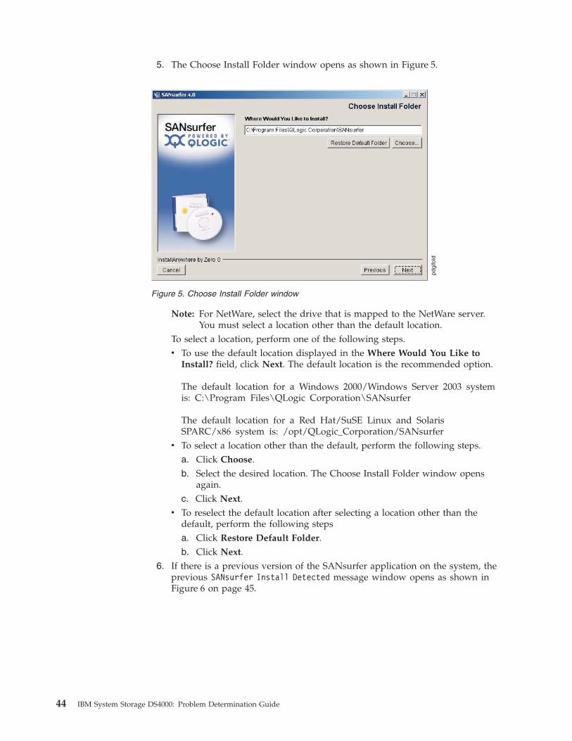
5. The Choose Install Folder window opens as shown in Figure 5.
Note: For NetWare, select the drive that is mapped to the NetWare server.
You must select a location other than the default location.
To select a location, perform one of the following steps.
v To use the default location displayed in the Where Would You Like to
Install? field, click Next. The default location is the recommended option.
The default location for a Windows 2000/Windows Server 2003 system
is: C:\Program Files\QLogic Corporation\SANsurfer
The default location for a Red Hat/SuSE Linux and Solaris
SPARC/x86 system is: /opt/QLogic_Corporation/SANsurfer
v To select a location other than the default, perform the following steps.
a. Click Choose.
b. Select the desired location. The Choose Install Folder window opens
again.
c. Click Next.v To reselect the default location after selecting a location other than the
default, perform the following steps
a. Click Restore Default Folder.
b. Click Next. 6. If there is a previous version of the SANsurfer application on the system, the
previous SANsurfer Install Detected message window opens as shown in
Figure 6 on page 45.
Figure 5. Choose Install Folder window
44 IBM System Storage DS4000: Problem Determination Guide

Attention: If the SANsurfer application is running currently, close it before
proceeding with the installation.
If a previous version is detected, you can choose to uninstall it or you can
install the new version of the SANsurfer application over the previous
version.
a. To uninstall the previous version, click Yes. Installation of the SANsurfer
application stops while the previous version is being uninstalled. Attention: If you are installing the SANsurfer application on a Windows
2000/Windows Server 2003 system, and you are prompted to restart the
system after the uninstall is complete, restart your system before installing
the new version in the same directory as the currently selected directory.
Otherwise, the newly installed SANsurfer application will not operate
properly.
b. To install the new version of the SANsurfer application without
uninstalling the previous version, click No. If the previously installed
version resides in the same directory as the currently selected directory, the
previous version is overwritten. 7. If you are installing the SANsurfer FC HBA Manager GUI on a Windows
2000/Windows Server 2003 system, the Select Shortcut Profile window opens
as shown in Figure 7
Figure 6. Previous SANsurfer Install Detected message
Figure 7. Select Shortcut Profile window
Chapter 4. Introduction to the QLogic SANsurfer application 45
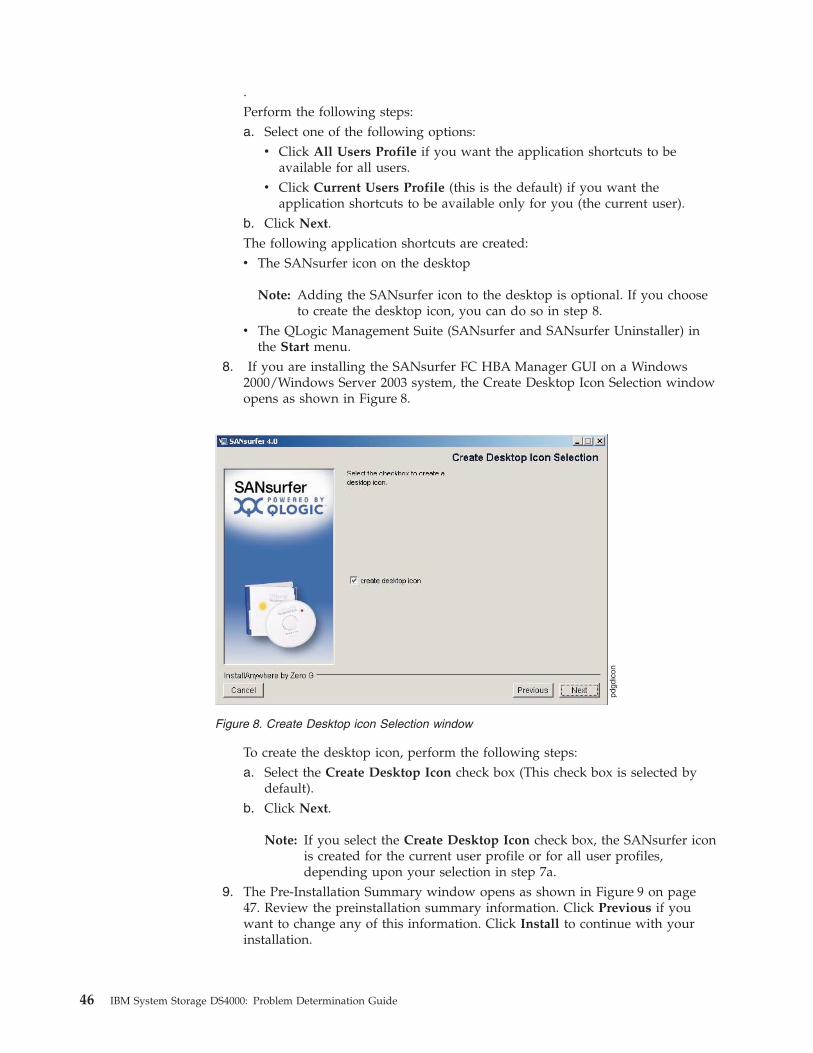
.
Perform the following steps:
a. Select one of the following options:
v Click All Users Profile if you want the application shortcuts to be
available for all users.
v Click Current Users Profile (this is the default) if you want the
application shortcuts to be available only for you (the current user).b. Click Next.
The following application shortcuts are created:
v The SANsurfer icon on the desktop
Note: Adding the SANsurfer icon to the desktop is optional. If you choose
to create the desktop icon, you can do so in step 8.
v The QLogic Management Suite (SANsurfer and SANsurfer Uninstaller) in
the Start menu. 8. If you are installing the SANsurfer FC HBA Manager GUI on a Windows
2000/Windows Server 2003 system, the Create Desktop Icon Selection window
opens as shown in Figure 8.
To create the desktop icon, perform the following steps:
a. Select the Create Desktop Icon check box (This check box is selected by
default).
b. Click Next.
Note: If you select the Create Desktop Icon check box, the SANsurfer icon
is created for the current user profile or for all user profiles,
depending upon your selection in step 7a. 9. The Pre-Installation Summary window opens as shown in Figure 9 on page
47. Review the preinstallation summary information. Click Previous if you
want to change any of this information. Click Install to continue with your
installation.
Figure 8. Create Desktop icon Selection window
46 IBM System Storage DS4000: Problem Determination Guide
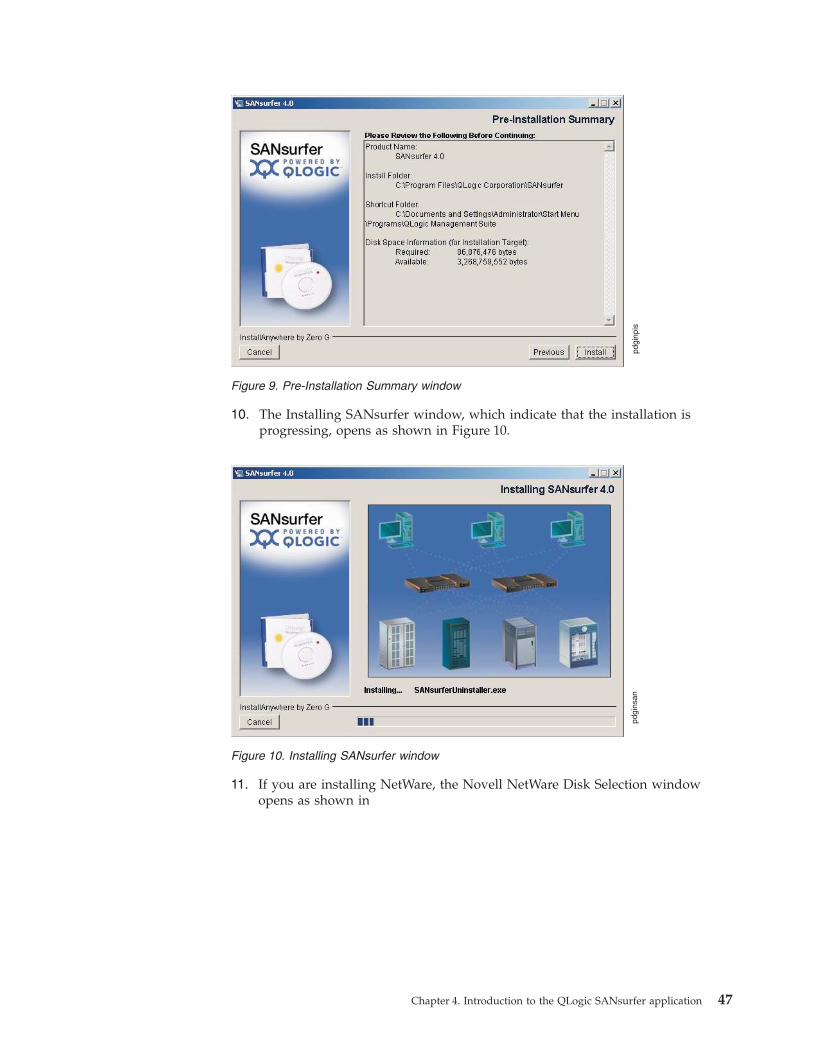
10. The Installing SANsurfer window, which indicate that the installation is
progressing, opens as shown in Figure 10.
11. If you are installing NetWare, the Novell NetWare Disk Selection window
opens as shown in
Figure 9. Pre-Installation Summary window
Figure 10. Installing SANsurfer window
Chapter 4. Introduction to the QLogic SANsurfer application 47
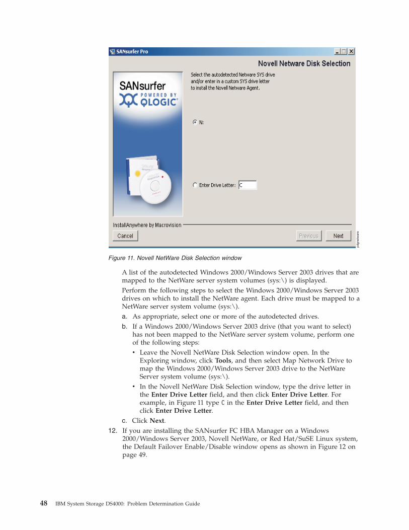
A list of the autodetected Windows 2000/Windows Server 2003 drives that are
mapped to the NetWare server system volumes (sys:\) is displayed.
Perform the following steps to select the Windows 2000/Windows Server 2003
drives on which to install the NetWare agent. Each drive must be mapped to a
NetWare server system volume (sys:\).
a. As appropriate, select one or more of the autodetected drives.
b. If a Windows 2000/Windows Server 2003 drive (that you want to select)
has not been mapped to the NetWare server system volume, perform one
of the following steps:
v Leave the Novell NetWare Disk Selection window open. In the
Exploring window, click Tools, and then select Map Network Drive to
map the Windows 2000/Windows Server 2003 drive to the NetWare
Server system volume (sys:\).
v In the Novell NetWare Disk Selection window, type the drive letter in
the Enter Drive Letter field, and then click Enter Drive Letter. For
example, in Figure 11 type C in the Enter Drive Letter field, and then
click Enter Drive Letter.c. Click Next.
12. If you are installing the SANsurfer FC HBA Manager on a Windows
2000/Windows Server 2003, Novell NetWare, or Red Hat/SuSE Linux system,
the Default Failover Enable/Disable window opens as shown in Figure 12 on
page 49.
Figure 11. Novell NetWare Disk Selection window
48 IBM System Storage DS4000: Problem Determination Guide

The Failover Configuration feature ensures data availability and system
reliability by assigning alternate path and automatic HBA failover for device
resources. For Linux systems, it is optional to use either the QLogic Failover
Configuration or the IBM DS4000 RDAC driver. Attention: For Windows, NetWare, and Solaris systems, do not enable QLogic
Failover Configuration. The IBM DS4000 RDAC driver that is provided with
your Storage Manager software is used for failover configuration.
To enable failover, perform the following steps:
a. Depending on your operation system, either select or clear the Enable
Failover Configuration check box.
b. Click Next.13. The Install Complete window opens as shown in Figure 13 on page 50. Click
Done.
Figure 12. Default QLogic Failover Enable/Disable window
Chapter 4. Introduction to the QLogic SANsurfer application 49
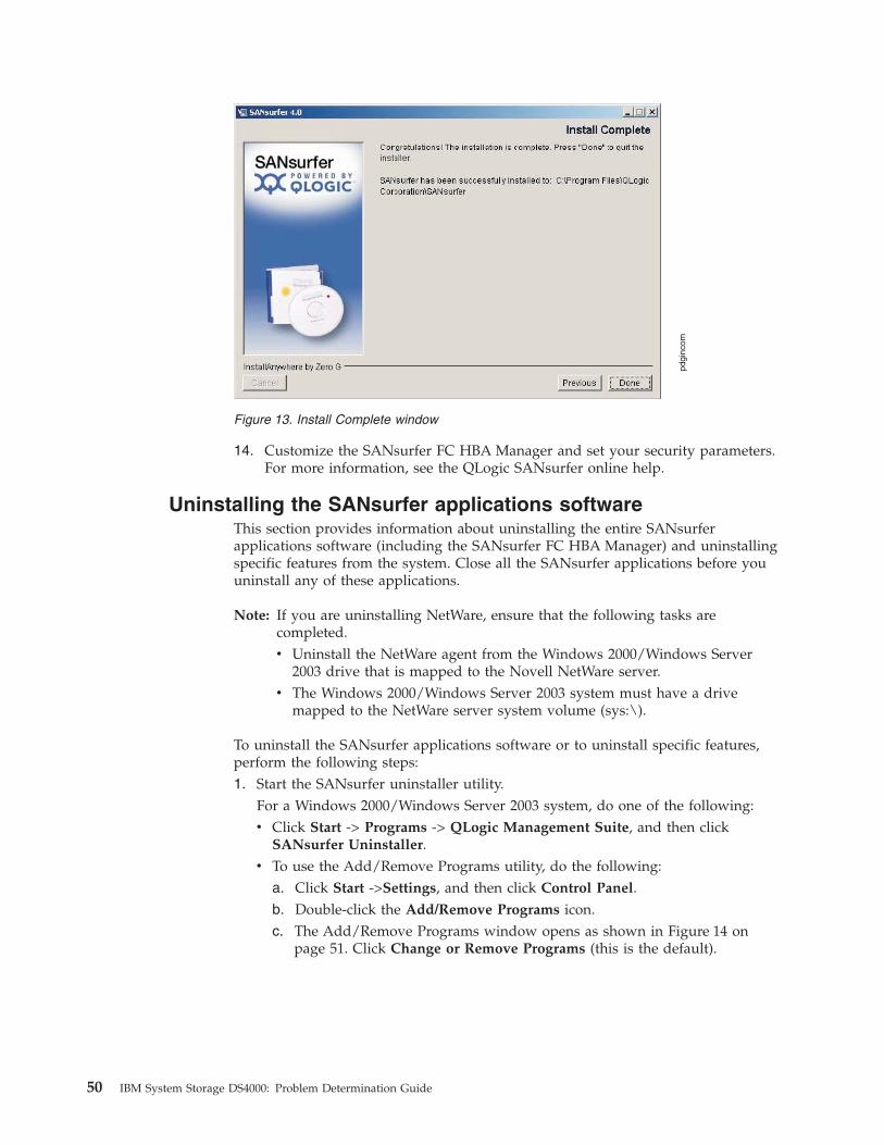
14. Customize the SANsurfer FC HBA Manager and set your security parameters.
For more information, see the QLogic SANsurfer online help.
Uninstalling the SANsurfer applications software
This section provides information about uninstalling the entire SANsurfer
applications software (including the SANsurfer FC HBA Manager) and uninstalling
specific features from the system. Close all the SANsurfer applications before you
uninstall any of these applications.
Note: If you are uninstalling NetWare, ensure that the following tasks are
completed.
v Uninstall the NetWare agent from the Windows 2000/Windows Server
2003 drive that is mapped to the Novell NetWare server.
v The Windows 2000/Windows Server 2003 system must have a drive
mapped to the NetWare server system volume (sys:\).
To uninstall the SANsurfer applications software or to uninstall specific features,
perform the following steps:
1. Start the SANsurfer uninstaller utility.
For a Windows 2000/Windows Server 2003 system, do one of the following:
v Click Start -> Programs -> QLogic Management Suite, and then click
SANsurfer Uninstaller.
v To use the Add/Remove Programs utility, do the following:
a. Click Start ->Settings, and then click Control Panel.
b. Double-click the Add/Remove Programs icon.
c. The Add/Remove Programs window opens as shown in Figure 14 on
page 51. Click Change or Remove Programs (this is the default).
Figure 13. Install Complete window
50 IBM System Storage DS4000: Problem Determination Guide

d. Select SANsurfer x.x.
e. Click Change/Remove.
For a Red Hat/SuSE Linux or Solaris SPARC/x86 system, do one of the
following, and then press Enter.
v On a Red Hat/SuSE Linux system, if /usr/local/bin is in the path, type
SANsurferUninstaller.
v On a Solaris SPARC/x86 system, if /usr/bin is in the path, type
SANsurferUninstaller.
v On a Red Hat/SuSE Linux system (if /usr/local/bin is not in the path) or a
Solaris SPARC/x86 system (if /usr/bin is not in the path), do the following:
a. Navigate to the directory where the SANsurfer application is installed.
The default location is /opt/QLogic_Corporation/SANsurfer
/UninstallData.
b. Type ./SANsurferUninstaller.2. The Uninstall SANsurfer window opens with SANsurfer x.x as the program to
be uninstalled as shown in Figure 15 on page 52. Click Next.
Figure 14. Add/Remove Programs window
Chapter 4. Introduction to the QLogic SANsurfer application 51
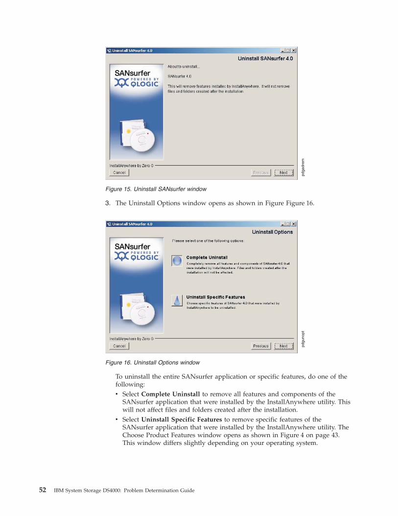
3. The Uninstall Options window opens as shown in Figure Figure 16.
To uninstall the entire SANsurfer application or specific features, do one of the
following:
v Select Complete Uninstall to remove all features and components of the
SANsurfer application that were installed by the InstallAnywhere utility. This
will not affect files and folders created after the installation.
v Select Uninstall Specific Features to remove specific features of the
SANsurfer application that were installed by the InstallAnywhere utility. The
Choose Product Features window opens as shown in Figure 4 on page 43.
This window differs slightly depending on your operating system.
Figure 15. Uninstall SANsurfer window
Figure 16. Uninstall Options window
52 IBM System Storage DS4000: Problem Determination Guide

a. Clear the applicable check box for each feature that you want to uninstall.
All features with selected check boxes will remain installed on your
system. Select from the following components. (All the components might
not be displayed and the order of the components might vary.)
For a Windows 2000/Windows Server 2003 system:
– SANsurfer FC HBA Manager
– SANsurfer FC NetWare 5/6.x Agent
– SANsurfer FC Windows NT 4/2000/2003 Agent
– Help
For a Red Hat/SuSE Linux system:
– SANsurfer FC HBA Manager
– SANsurfer FC Linux Agent
– Help
For a Solaris SPARC/x86 system:
– SANsurfer FC HBA Manager GUI
– SANsurfer FC Solaris Agent
– Helpb. Click Uninstall.
4. The Uninstall SANsurfer window contains a list of the features that are being
uninstalled, as shown in Figure 15 on page 52.
Figure 17. Choose Product Features window
Chapter 4. Introduction to the QLogic SANsurfer application 53
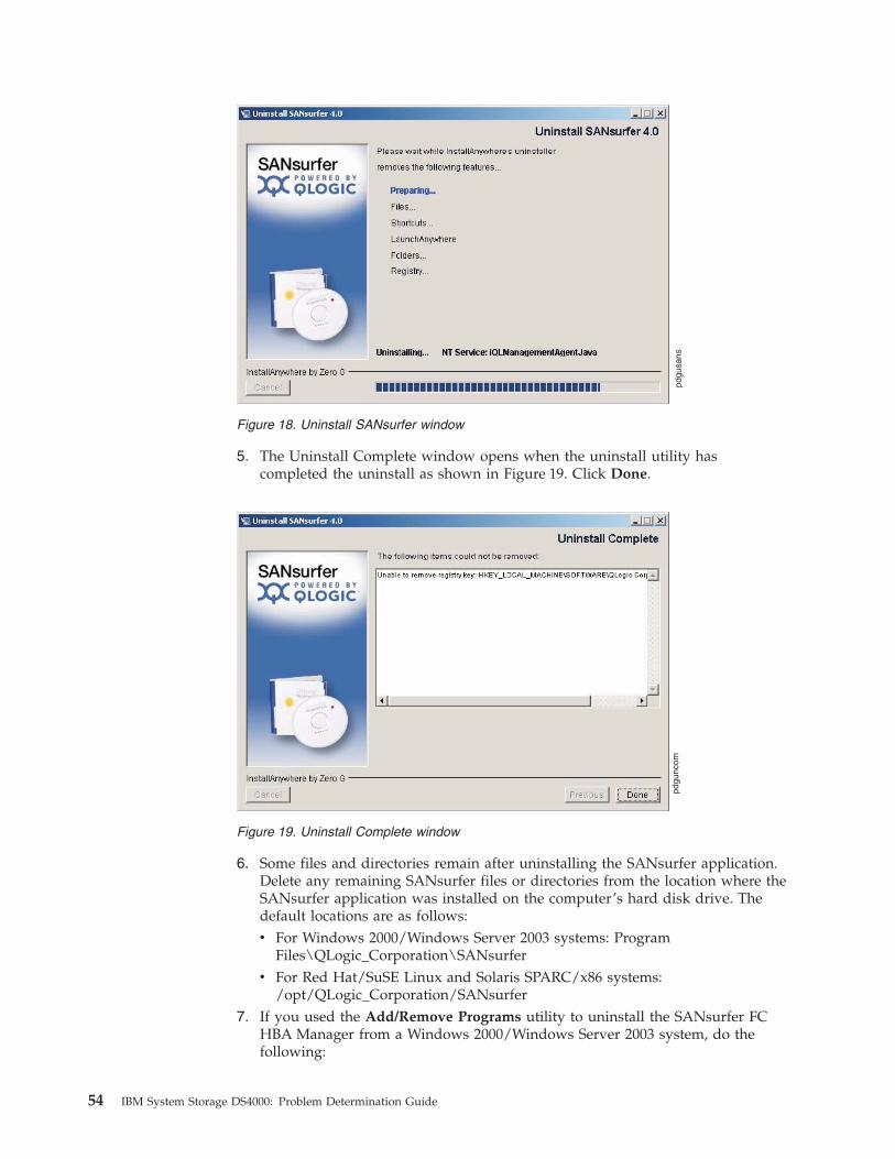
5. The Uninstall Complete window opens when the uninstall utility has
completed the uninstall as shown in Figure 19. Click Done.
6. Some files and directories remain after uninstalling the SANsurfer application.
Delete any remaining SANsurfer files or directories from the location where the
SANsurfer application was installed on the computer’s hard disk drive. The
default locations are as follows:
v For Windows 2000/Windows Server 2003 systems: Program
Files\QLogic_Corporation\SANsurfer
v For Red Hat/SuSE Linux and Solaris SPARC/x86 systems:
/opt/QLogic_Corporation/SANsurfer7. If you used the Add/Remove Programs utility to uninstall the SANsurfer FC
HBA Manager from a Windows 2000/Windows Server 2003 system, do the
following:
Figure 18. Uninstall SANsurfer window
Figure 19. Uninstall Complete window
54 IBM System Storage DS4000: Problem Determination Guide

a. Click Cancel to close the Add/Remove Programs window.
b. Click Close to close the Control Panel.8. If prompted to do so, restart the system.
SANsurfer FC HBA Manager features
The SANsurfer FC HBA Manager has the following features:
v Asset management Connect to and disconnect from local and remote hosts. The
SANsurfer FC HBA Manager also provides information about connected hosts
and their attached QLogic HBAs with connected storage devices.
v Configuration management Configure local and remote systems. Use the
SANsurfer FC HBA Manager to do the following tasks:
– Configure QLogic Fibre Channel HBAs.
– Configure Fibre Channel devices.
– Compare hosts. View the differences between the current host and any saved
host configuration, to see what has changed in the SAN.
– Configure LUNs for a device (load balancing).
See the SANblade HBA Support Matrix (Fibre Channel & iSCSI) on the
SANsurfer CD for a list of HBAs that support LUN load balancing.
Support for additional operating systems and HBAs will be added in future
versions of the SANsurfer FC HBA Manager.
– Configure LUN path failover. See the SANblade HBA Support Matrix (Fibre
Channel & iSCSI) on the SANsurfer CD for a list of HBAs that support LUN
path failover.
– Support for additional operating systems and HBAs will be added in future
versions of the SANsurfer FC HBA Manager.
– Persistently bind targets.
– Replace devices.
– Update the NVRAM, flash BIOS, and HBA driver.v Statistics The SANsurfer FC HBA Manager provides statistics for each host and
HBA port. These statistics can be collected automatically or by request; they can
be reset at any time. In addition, you can export the statistics to a comma
separated values (CSV) file that can be imported into other applications, such as
Microsoft Excel.
v Diagnostics The SANsurfer FC HBA Manager provides end-to-end diagnostics
that enable you to test the HBAs and the devices to which they are connected.
The SANsurfer FC HBA Manager diagnostics allow you to do the following
tasks:
– Test the link status of each HBA and its attached devices
– Perform a loopback test, which is external to the HBA, to evaluate the ports
(transmit and receive transceivers) on the HBA and the error rate.
– Perform a read/write buffer test, which tests the link between the HBA and
its attached devices.v Alarm and event notifications The SANsurfer FC HBA Manager provides
asynchronous notification of various conditions and problems through alarms
and events. Alarm information includes severity, time, host, HBA, application,
and description. Event information includes severity, time, and message. In
addition, the alarm and event information can be exported to a CSV file that can
be imported into other applications, such as Microsoft Excel. Alarm information
can be sent automatically by e-mail to a distribution list.
Chapter 4. Introduction to the QLogic SANsurfer application 55
QLogic SANsurfer basic features overview
This section lists the SANsurfer features and contains general information needed
to run the SANsurfer application on any supported platform.
For additional details about the SANsurfer functions, refer to the SANsurfer online
help.
Features
The SANsurfer application enables you to perform the following actions:
v Set the SANsurfer options
v Connect to hosts
v Disconnect from a host
v View extensive event and alarm log information
v Use host-to-host SAN configuration policies
v Configure port devices
v Use LUN Level configuration
v Watch real time to see when failovers occur with the Failover Watcher
v Control host-side agent operations, including setting the host agent polling
interval
v Review host adapter information, including:
– General information
– Statistics
– Information on attached devices
– Attached device link statusv Perform adapter functions, including:
– Configure adapter NVRAM settings
– Run fibre channel diagnostics (read/write and loopback tests)
– Perform flash updates on an adapter
– Perform NVRAM updates on an adapterv Manage configurations
– Save configurations for offline policy checks and SAN integrity
– Load configurations from file if host is offline for policy checks and SAN
integrityv Confirm security
Options
To configure the SANsurfer application, click View, and then click Options. The
Options window opens.
The Options window has four panels and two buttons:
v Event Log
v Alarm Log
v Warning Displays
v Configuration Change Alarm
v OK (save changes) and Cancel (discard changes) buttons
The Options window functions are described in the following sections.
56 IBM System Storage DS4000: Problem Determination Guide

Event log
The event log size can be restricted to a certain number of entries. If the log size is
reached, the oldest entries are removed to allow space for the newest entries. The
current log size can range from 20 to 200 event entries. If information or warning
events are to be logged, click the associated check box. Logged information
includes: communication and file system errors. The SANsurfer application stores
the event entries in a file called ’events.txt’.
Example entries follow:
Tue Dec 23 16:22:29 PST 2003, 4, RPC request 42 for Host 10.3.10.64
failed., 2
Tue Dec 23 16:22:29 PST 2003, 4, Retrying RPC request 42 for Host
10.3.10.64., 2
Tue Dec 23 16:22:30 PST 2003, 4, RPC request 42 for Host 10.3.10.64
failed., 2
Tue Dec 23 16:22:30 PST 2003, 4, Retrying RPC request 42 for Host
10.3.10.64., 2
Tue Dec 23 16:22:30 PST 2003, 4, RPC request 42 for Host 10.3.10.64
failed., 2
Alarm log
While the SANsurfer application communicates with a host, the application
continually receives notification messages from the host indicating various changes
directly or indirectly made on a host’s adapter(s). The log size can be restricted to
a certain number of entries. If the log size is reached, the oldest entries are
removed to allow space for the newest entries. The current log size can range from
20 to 200 event entries. Logged information includes: status, configuration and
NVRAM changes. The SANsurfer application stores the alarm entries in a file
called ’alarms.txt’.
Example entries follow:
Wed Dec 24 10:27:28 PST 2003, qlogic-agc001, 1-QLA2300/2310, 0, Status
Change: Good Status. Loop Down., 1
Wed Dec 24 10:27:28 PST 2003, qlogic-agc001, 4-QLA2350, 0, Status Change:
Good Status. Loop Down., 1
Wed Dec 24 10:27:50 PST 2003, qlogic-agc001, 1-QLA2300/2310, 0, Status
Change: Good Status. Loop Down., 1
Wed Dec 24 10:27:50 PST 2003, qlogic-agc001, 4-QLA2350, 0, Status Change:
Good Status. Loop Down., 1
Warning displays
The SANsurfer application displays additional warning dialogs throughout the
application. By default, the Warning Displays option is enabled. To disable the
display of warning dialogs, clear the Enable warning displays check box in the
Options window.
Chapter 4. Introduction to the QLogic SANsurfer application 57
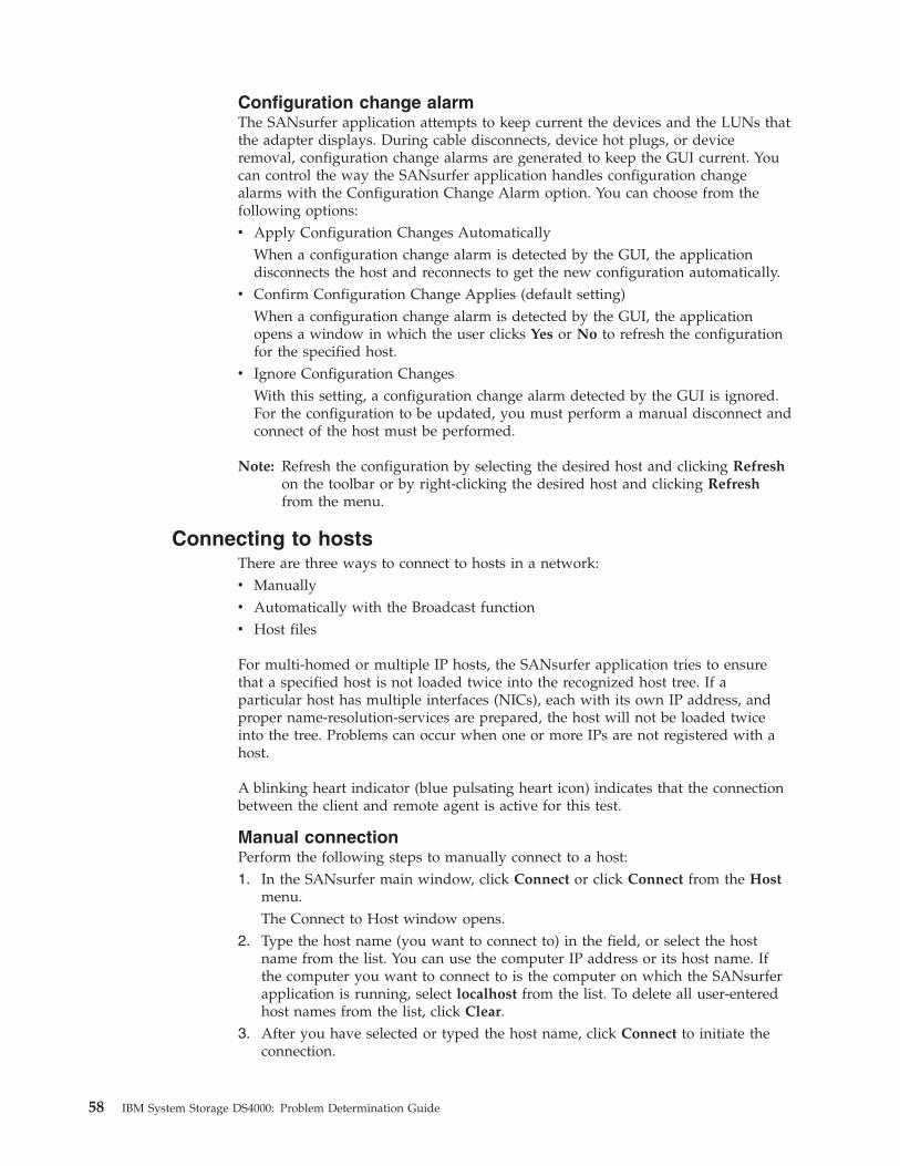
Configuration change alarm
The SANsurfer application attempts to keep current the devices and the LUNs that
the adapter displays. During cable disconnects, device hot plugs, or device
removal, configuration change alarms are generated to keep the GUI current. You
can control the way the SANsurfer application handles configuration change
alarms with the Configuration Change Alarm option. You can choose from the
following options:
v Apply Configuration Changes Automatically
When a configuration change alarm is detected by the GUI, the application
disconnects the host and reconnects to get the new configuration automatically.
v Confirm Configuration Change Applies (default setting)
When a configuration change alarm is detected by the GUI, the application
opens a window in which the user clicks Yes or No to refresh the configuration
for the specified host.
v Ignore Configuration Changes
With this setting, a configuration change alarm detected by the GUI is ignored.
For the configuration to be updated, you must perform a manual disconnect and
connect of the host must be performed.
Note: Refresh the configuration by selecting the desired host and clicking Refresh
on the toolbar or by right-clicking the desired host and clicking Refresh
from the menu.
Connecting to hosts
There are three ways to connect to hosts in a network:
v Manually
v Automatically with the Broadcast function
v Host files
For multi-homed or multiple IP hosts, the SANsurfer application tries to ensure
that a specified host is not loaded twice into the recognized host tree. If a
particular host has multiple interfaces (NICs), each with its own IP address, and
proper name-resolution-services are prepared, the host will not be loaded twice
into the tree. Problems can occur when one or more IPs are not registered with a
host.
A blinking heart indicator (blue pulsating heart icon) indicates that the connection
between the client and remote agent is active for this test.
Manual connection
Perform the following steps to manually connect to a host:
1. In the SANsurfer main window, click Connect or click Connect from the Host
menu.
The Connect to Host window opens.
2. Type the host name (you want to connect to) in the field, or select the host
name from the list. You can use the computer IP address or its host name. If
the computer you want to connect to is the computer on which the SANsurfer
application is running, select localhost from the list. To delete all user-entered
host names from the list, click Clear.
3. After you have selected or typed the host name, click Connect to initiate the
connection.
58 IBM System Storage DS4000: Problem Determination Guide

If the connection attempt fails, an error message is displayed indicating the
failure and potential causes. If the connection is successfully established, the
host’s name and its adapters are shown on the HBA tree.
Click Cancel to stop the connection process and return to the main window.
Broadcast connections
the SANsurfer application can auto-connect to all hosts running an agent in a
network. For auto-connect to function properly, ensure that the Broadcast setting is
enabled. To enable auto-connect, select the Auto Connect check box from the
Settings menu. To disable auto-connect, clear the Auto Connect check box.
Note: If multiple NICs are present in the system, the SANsurfer client will
broadcast to the first IP address subnet based on the binding order.
Therefore, ensure that the NIC for the local subnet is first in the binding
order. If this is not done, the diagnostics might not run properly and remote
connection might not occur. See the readme file in the release package for
more information.
Host files
The final way that the SANsurfer application provides to connect to a specified
agent or agents is by using a host file to connect to all specified hosts (that are
present in the file). The feature can be useful if you (the system administrator)
have to manage a number of fibre channel attached hosts that are in the same SAN
and do not want to connect to each of the host(s) individually.
Creating a Host File: Perform the following steps to save the group of hosts that
display in the HBA tree to a host file.
1. Do one of the following:
v From the Host menu In the SANsurfer main window, click Save Group.
v Right-click the HBA tree. From the menu, click Save Group.2. The Save window opens. Save the host file (.hst) in an appropriate directory.
Click Save.
Note: You can also create a host file (.hst) from the command line. The format of
the file is one host name per line, for example:
adsw2ksys2
nt4ssys1
nw51sys7
Using a Host File to Connect to Hosts: Perform the following steps to connect to
a group of hosts using a previously created host file.
1. Do one of the following:
v From the Host menu In the SANsurfer main window, click Open Group.
v Right-click the HBA tree. From the menu, click Open Group.2. The ″Open″ window opens. Save the host file (.hst) that contains the hosts to
which you want to connect. Click Open. The host names are displayed in the
SANsurfer main window HBA tree.
Disconnecting from a host
Perform the following steps to disconnect from a host:
1. From the HBA tree in the SANsurfer main window, click the name of host from
which you want to disconnect.
2. Click Host -> Disconnect.
Chapter 4. Introduction to the QLogic SANsurfer application 59

When a host is disconnected, its entry in the HBA tree is removed.
Polling interval
You can set polling intervals on a per-host basis to retrieve information. The
polling interval setting can be in the range from 1 second to 3600 seconds (one
hour). Perform the following steps to set the polling interval:
1. From the HBA tree in the SANsurfer main window, click the host name.
2. Click Host -> Polling. The ″Polling Settings - target″ window opens.
3. Type the new polling interval, and then click OK.
Security
the SANsurfer application protects everything written to the adapter or adapter
configuration with an agent-side password. You can set the host agent password
from any host that can run the SANsurfer GUI and connect to the host agent.
When a configuration change is requested, the Security Check window opens. Type
the application-access password to validate it.
To change a host agent password, click the host name in the HBA tree. The
Information/Security window opens. Click the Security tab to open the Security
page.
The security page is divided into two panels: Host Access and Application Access.
Host access
The Host Access panel verifies that the host user login and password has
administrator or root privileges before an application access is attempted. The
login and password values are the same as those used to access the computer.
Login A host user account with administrator or root-level rights.
Password
The password for the host user account.
Application access
The Application Access panel enables you to change the SANsurfer host agent
password. To change the password, type the following information in the
following fields:
Old password
The current application-access password for the host. The original default
password is config. Immediately change the default password to a new
password.
New password
The new application-access password for the host.
Verify Password
The new application-access password for host verification.
The Help menu
From the SANsurfer Help menu, you can specify the location of the browser to
open when help is requested by a user. You can also view the SANsurfer
application version information.
The Help menu contains the following items:
60 IBM System Storage DS4000: Problem Determination Guide
v Set Browser Location
Opens the Browser Location window. Type the file path of the browser that the
SANsurfer application opens when a user requests help, or click Browse to
navigate to the file location.
v Browse Contents
Opens the SANsurfer help.
v About
Displays information about the SANsurfer application, including the current
SANsurfer version number.
Chapter 4. Introduction to the QLogic SANsurfer application 61

62 IBM System Storage DS4000: Problem Determination Guide

Chapter 5. PD hints: Common path/single path configurations
You should be referred to this chapter from a PD map or indication. If this is not
the case, see Chapter 2, “Problem determination starting points,” on page 3.
After you read the relevant information in this chapter, return to “Common Path
PD map 1” on page 20.
In Figure 20, the HBA, HBA-to-concentrator cable, and the port that this cable uses
are on the common path to all storage. The other cables and ports to the
controllers are on their own paths so that a failure on them does not affect the
others. This configuration is referred to a common or single path.
Table 3. Description of Figure 20
Number Description
�1� FC host adapter (HBA)
�2� Common path—concentrator to HBA
�3� Concentrator
�4� Single path(s)—Concentrator to controller
�5� Controller A
�6� Controller B
Figure 20. Common path configuration
© Copyright IBM Corp. 2006 63

64 IBM System Storage DS4000: Problem Determination Guide
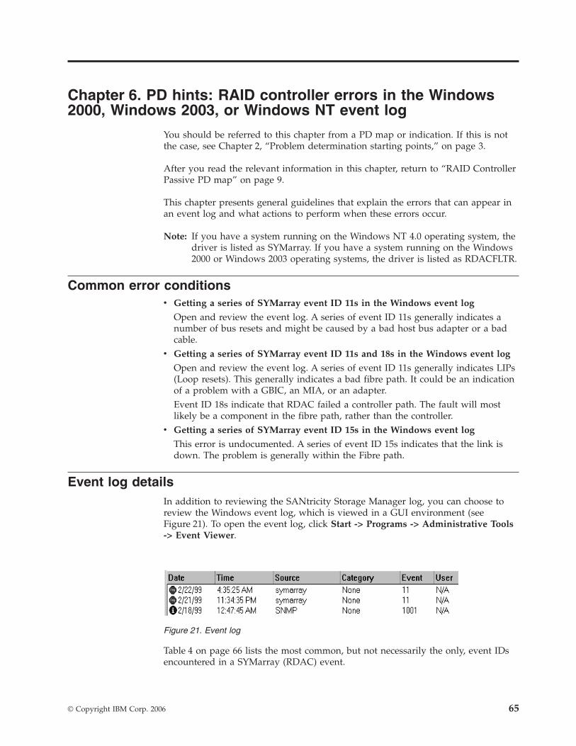
Chapter 6. PD hints: RAID controller errors in the Windows
2000, Windows 2003, or Windows NT event log
You should be referred to this chapter from a PD map or indication. If this is not
the case, see Chapter 2, “Problem determination starting points,” on page 3.
After you read the relevant information in this chapter, return to “RAID Controller
Passive PD map” on page 9.
This chapter presents general guidelines that explain the errors that can appear in
an event log and what actions to perform when these errors occur.
Note: If you have a system running on the Windows NT 4.0 operating system, the
driver is listed as SYMarray. If you have a system running on the Windows
2000 or Windows 2003 operating systems, the driver is listed as RDACFLTR.
Common error conditions
v Getting a series of SYMarray event ID 11s in the Windows event log
Open and review the event log. A series of event ID 11s generally indicates a
number of bus resets and might be caused by a bad host bus adapter or a bad
cable.
v Getting a series of SYMarray event ID 11s and 18s in the Windows event log
Open and review the event log. A series of event ID 11s generally indicates LIPs
(Loop resets). This generally indicates a bad fibre path. It could be an indication
of a problem with a GBIC, an MIA, or an adapter.
Event ID 18s indicate that RDAC failed a controller path. The fault will most
likely be a component in the fibre path, rather than the controller.
v Getting a series of SYMarray event ID 15s in the Windows event log
This error is undocumented. A series of event ID 15s indicates that the link is
down. The problem is generally within the Fibre path.
Event log details
In addition to reviewing the SANtricity Storage Manager log, you can choose to
review the Windows event log, which is viewed in a GUI environment (see
Figure 21). To open the event log, click Start -> Programs -> Administrative Tools
-> Event Viewer.
Table 4 on page 66 lists the most common, but not necessarily the only, event IDs
encountered in a SYMarray (RDAC) event.
Figure 21. Event log
© Copyright IBM Corp. 2006 65

Table 4. Common SYMarray (RDAC) event IDs
Event Microsoft Label Identifier Description
9 IO_ERR_TIMEOUT The device %s did not respond within timeout period.
11 IO_ERR_CONTROLLER_ERROR Driver detected controller failure.
16 ERR_INVALID_REQUEST The request is incorrectly formatted for %1.
18 IO_LAYERED_FAILURE Driver beneath this layer failed.
389 STATUS_IO_DEVICE_ERROR The I/O device reported an I/O error.
Event ID 18 is a special case. SYMarray uses event ID 18 to designate a failed
controller path. (The controller on the physical path is the failed controller.) All
LEDs on the controller are usually lit when a failure occurs. This does not
necessarily mean that the controller is defective, but rather that a component along
the path to the controller is generating errors. Possible problem components
include the host adapter, fibre cable, GBIC, hub, and so on.
In a multi-node cluster with multiple event ID 18s, the earliest log entry most
likely initiated the original controller failure. Event ID 18s on other nodes were
most likely responses to the original failure and typically contain an SRB status of
(0x0a - SCSI Selection Timeout). Check the system date and time stamp for
synchronization to validate which entry occurred first. To review an entry in the
Event Viewer, perform the following steps:
1. Double-click the entry you want to review.
2. Select the Words radio button to convert the bottom text from bytes to words.
See Figure 22.
A. The last four digits (2 bytes) in this field indicate the unique error value. In this
example, the error value shown indicates a Controller Failover Event.
Figure 22. Event detail
66 IBM System Storage DS4000: Problem Determination Guide
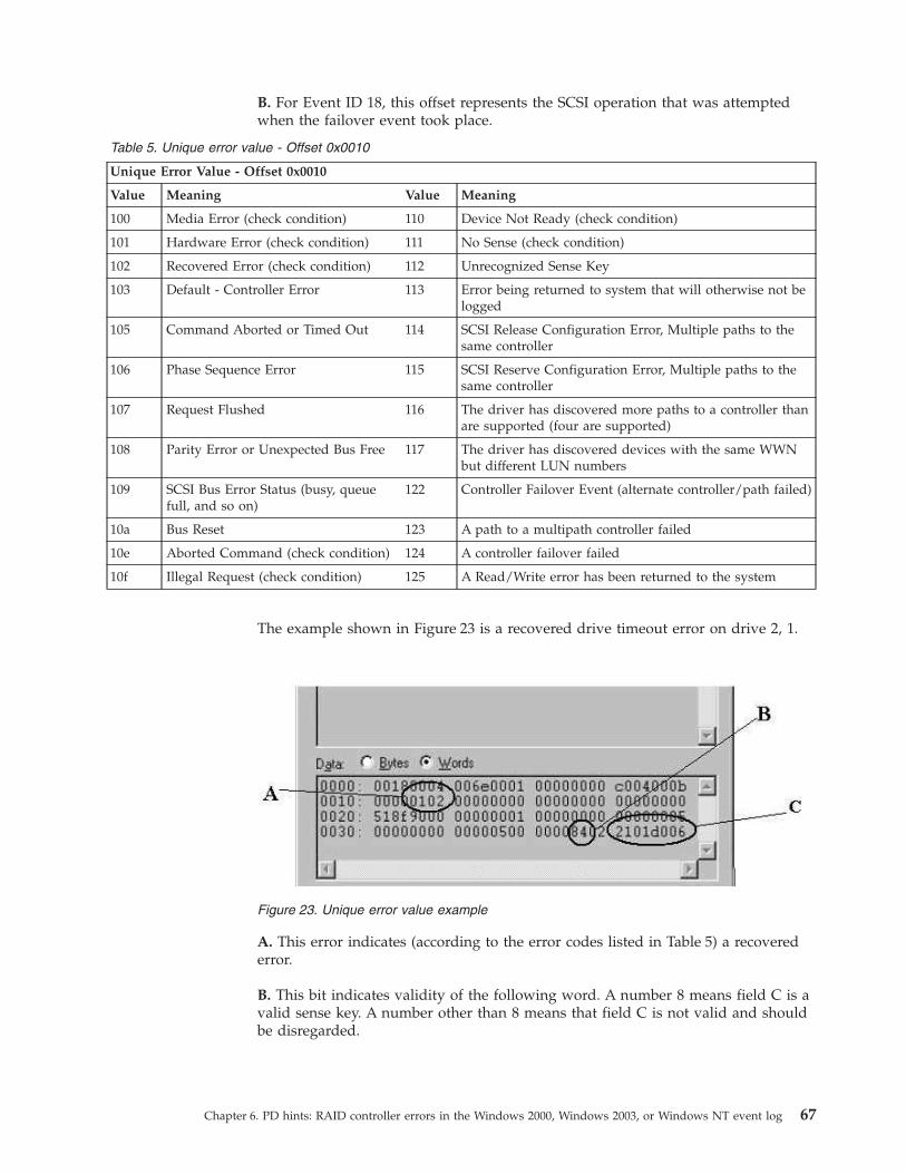
B. For Event ID 18, this offset represents the SCSI operation that was attempted
when the failover event took place.
Table 5. Unique error value - Offset 0x0010
Unique Error Value - Offset 0x0010
Value Meaning Value Meaning
100 Media Error (check condition) 110 Device Not Ready (check condition)
101 Hardware Error (check condition) 111 No Sense (check condition)
102 Recovered Error (check condition) 112 Unrecognized Sense Key
103 Default - Controller Error 113 Error being returned to system that will otherwise not be
logged
105 Command Aborted or Timed Out 114 SCSI Release Configuration Error, Multiple paths to the
same controller
106 Phase Sequence Error 115 SCSI Reserve Configuration Error, Multiple paths to the
same controller
107 Request Flushed 116 The driver has discovered more paths to a controller than
are supported (four are supported)
108 Parity Error or Unexpected Bus Free 117 The driver has discovered devices with the same WWN
but different LUN numbers
109 SCSI Bus Error Status (busy, queue
full, and so on)
122 Controller Failover Event (alternate controller/path failed)
10a Bus Reset 123 A path to a multipath controller failed
10e Aborted Command (check condition) 124 A controller failover failed
10f Illegal Request (check condition) 125 A Read/Write error has been returned to the system
The example shown in Figure 23 is a recovered drive timeout error on drive 2, 1.
A. This error indicates (according to the error codes listed in Table 5) a recovered
error.
B. This bit indicates validity of the following word. A number 8 means field C is a
valid sense key. A number other than 8 means that field C is not valid and should
be disregarded.
Figure 23. Unique error value example
Chapter 6. PD hints: RAID controller errors in the Windows 2000, Windows 2003, or Windows NT event log 67
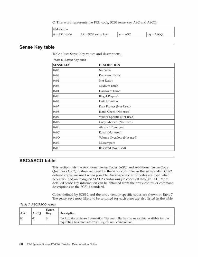
C. This word represents the FRU code, SCSI sense key, ASC and ASCQ.
ffkkaaqq –
ff = FRU code kk = SCSI sense key aa = ASC qq = ASCQ
Sense Key table
Table 6 lists Sense Key values and descriptions.
Table 6. Sense Key table
SENSE KEY DESCRIPTION
0x00 No Sense
0x01 Recovered Error
0x02 Not Ready
0x03 Medium Error
0x04 Hardware Error
0x05 Illegal Request
0x06 Unit Attention
0x07 Data Protect (Not Used)
0x08 Blank Check (Not used)
0x09 Vendor Specific (Not used)
0x0A Copy Aborted (Not used)
0x0B Aborted Command
0x0C Equal (Not used)
0x0D Volume Overflow (Not used)
0x0E Miscompare
0x0F Reserved (Not used)
ASC/ASCQ table
This section lists the Additional Sense Codes (ASC) and Additional Sense Code
Qualifier (ASCQ) values returned by the array controller in the sense data. SCSI-2
defined codes are used when possible. Array-specific error codes are used when
necessary, and are assigned SCSI-2 vendor-unique codes 80 through FFH. More
detailed sense key information can be obtained from the array controller command
descriptions or the SCSI-2 standard.
Codes defined by SCSI-2 and the array vendor-specific codes are shown in Table 7.
The sense keys most likely to be returned for each error are also listed in the table.
Table 7. ASC/ASCQ values
ASC ASCQ
Sense
Key Description
00 00 0 No Additional Sense Information The controller has no sense data available for the
requesting host and addressed logical unit combination.
68 IBM System Storage DS4000: Problem Determination Guide
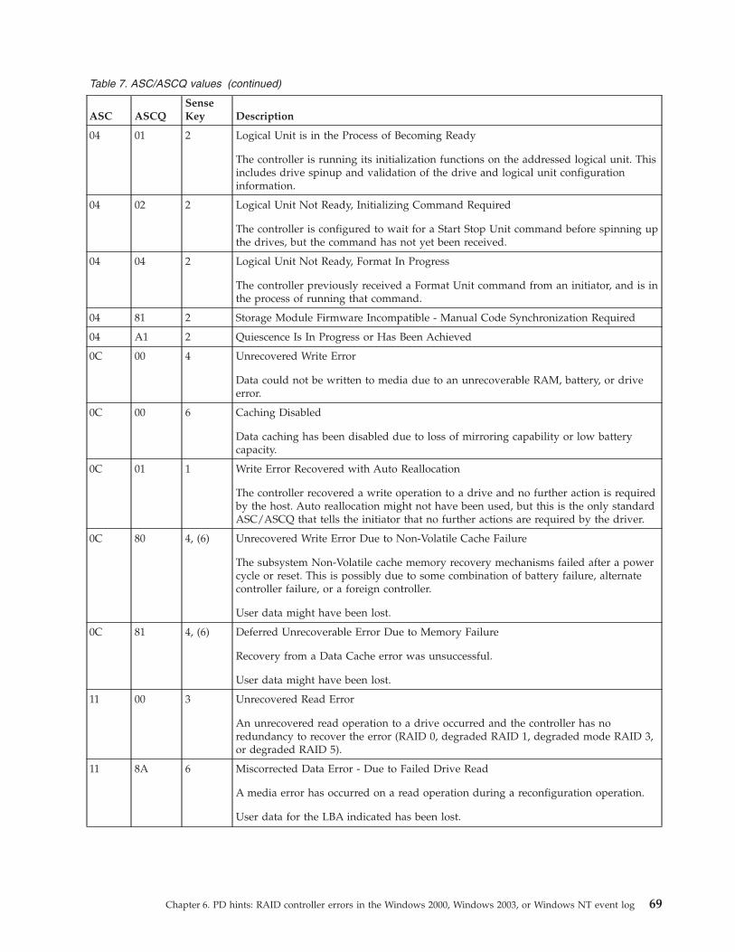
Table 7. ASC/ASCQ values (continued)
ASC ASCQ
Sense
Key Description
04 01 2 Logical Unit is in the Process of Becoming Ready
The controller is running its initialization functions on the addressed logical unit. This
includes drive spinup and validation of the drive and logical unit configuration
information.
04 02 2 Logical Unit Not Ready, Initializing Command Required
The controller is configured to wait for a Start Stop Unit command before spinning up
the drives, but the command has not yet been received.
04 04 2 Logical Unit Not Ready, Format In Progress
The controller previously received a Format Unit command from an initiator, and is in
the process of running that command.
04 81 2 Storage Module Firmware Incompatible - Manual Code Synchronization Required
04 A1 2 Quiescence Is In Progress or Has Been Achieved
0C 00 4 Unrecovered Write Error
Data could not be written to media due to an unrecoverable RAM, battery, or drive
error.
0C 00 6 Caching Disabled
Data caching has been disabled due to loss of mirroring capability or low battery
capacity.
0C 01 1 Write Error Recovered with Auto Reallocation
The controller recovered a write operation to a drive and no further action is required
by the host. Auto reallocation might not have been used, but this is the only standard
ASC/ASCQ that tells the initiator that no further actions are required by the driver.
0C 80 4, (6) Unrecovered Write Error Due to Non-Volatile Cache Failure
The subsystem Non-Volatile cache memory recovery mechanisms failed after a power
cycle or reset. This is possibly due to some combination of battery failure, alternate
controller failure, or a foreign controller.
User data might have been lost.
0C 81 4, (6) Deferred Unrecoverable Error Due to Memory Failure
Recovery from a Data Cache error was unsuccessful.
User data might have been lost.
11 00 3 Unrecovered Read Error
An unrecovered read operation to a drive occurred and the controller has no
redundancy to recover the error (RAID 0, degraded RAID 1, degraded mode RAID 3,
or degraded RAID 5).
11 8A 6 Miscorrected Data Error - Due to Failed Drive Read
A media error has occurred on a read operation during a reconfiguration operation.
User data for the LBA indicated has been lost.
Chapter 6. PD hints: RAID controller errors in the Windows 2000, Windows 2003, or Windows NT event log 69
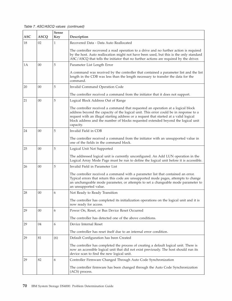
Table 7. ASC/ASCQ values (continued)
ASC ASCQ
Sense
Key Description
18 02 1 Recovered Data - Data Auto Reallocated
The controller recovered a read operation to a drive and no further action is required
by the host. Auto reallocation might not have been used, but this is the only standard
ASC/ASCQ that tells the initiator that no further actions are required by the driver.
1A 00 5 Parameter List Length Error
A command was received by the controller that contained a parameter list and the list
length in the CDB was less than the length necessary to transfer the data for the
command.
20 00 5 Invalid Command Operation Code
The controller received a command from the initiator that it does not support.
21 00 5 Logical Block Address Out of Range
The controller received a command that requested an operation at a logical block
address beyond the capacity of the logical unit. This error could be in response to a
request with an illegal starting address or a request that started at a valid logical
block address and the number of blocks requested extended beyond the logical unit
capacity.
24 00 5 Invalid Field in CDB
The controller received a command from the initiator with an unsupported value in
one of the fields in the command block.
25 00 5 Logical Unit Not Supported
The addressed logical unit is currently unconfigured. An Add LUN operation in the
Logical Array Mode Page must be run to define the logical unit before it is accessible.
26 00 5 Invalid Field in Parameter List
The controller received a command with a parameter list that contained an error.
Typical errors that return this code are unsupported mode pages, attempts to change
an unchangeable mode parameter, or attempts to set a changeable mode parameter to
an unsupported value.
28 00 6 Not Ready to Ready Transition
The controller has completed its initialization operations on the logical unit and it is
now ready for access.
29 00 6 Power On, Reset, or Bus Device Reset Occurred
The controller has detected one of the above conditions.
29 04 6 Device Internal Reset
The controller has reset itself due to an internal error condition.
29 81 (6) Default Configuration has been Created
The controller has completed the process of creating a default logical unit. There is
now an accessible logical unit that did not exist previously. The host should run its
device scan to find the new logical unit.
29 82 6 Controller Firmware Changed Through Auto Code Synchronization
The controller firmware has been changed through the Auto Code Synchronization
(ACS) process.
70 IBM System Storage DS4000: Problem Determination Guide

Table 7. ASC/ASCQ values (continued)
ASC ASCQ
Sense
Key Description
2A 01 6 Mode Parameters Changed
The controller received a request from another initiator to change the mode
parameters for the addressed logical unit. This error notifies the current initiator that
the change occurred.
This error might also be reported in the event that Mode Select parameters changed as
a result of a cache synchronization error during the processing of the most recent
Mode Select request.
2A 02 6 Log Parameters Changed
The controller received a request from another initiator to change the log parameters
for the addressed logical unit. This error notifies the current initiator that the change
occurred.
This error is returned when a Log Select command is issued to clear the AEN log
entries.
2F 00 6 Commands Cleared by Another Initiator
The controller received a Clear Queue message from another initiator. This error is to
notify the current initiator that the controller cleared the current initiators commands
if it had any outstanding.
31 01 1, 4 Format Command Failed
A Format Unit command issued to a drive returned an unrecoverable error.
32 00 4 Out of Alternates
A Reassign Blocks command to a drive failed.
3F 01 (6) Drive micro-code changed
3F 0E 6 Reported LUNs data has changed
Previous LUN data reported using a Report LUNs command has changed (due to
LUN creation or deletion or controller hot-swap).
Chapter 6. PD hints: RAID controller errors in the Windows 2000, Windows 2003, or Windows NT event log 71
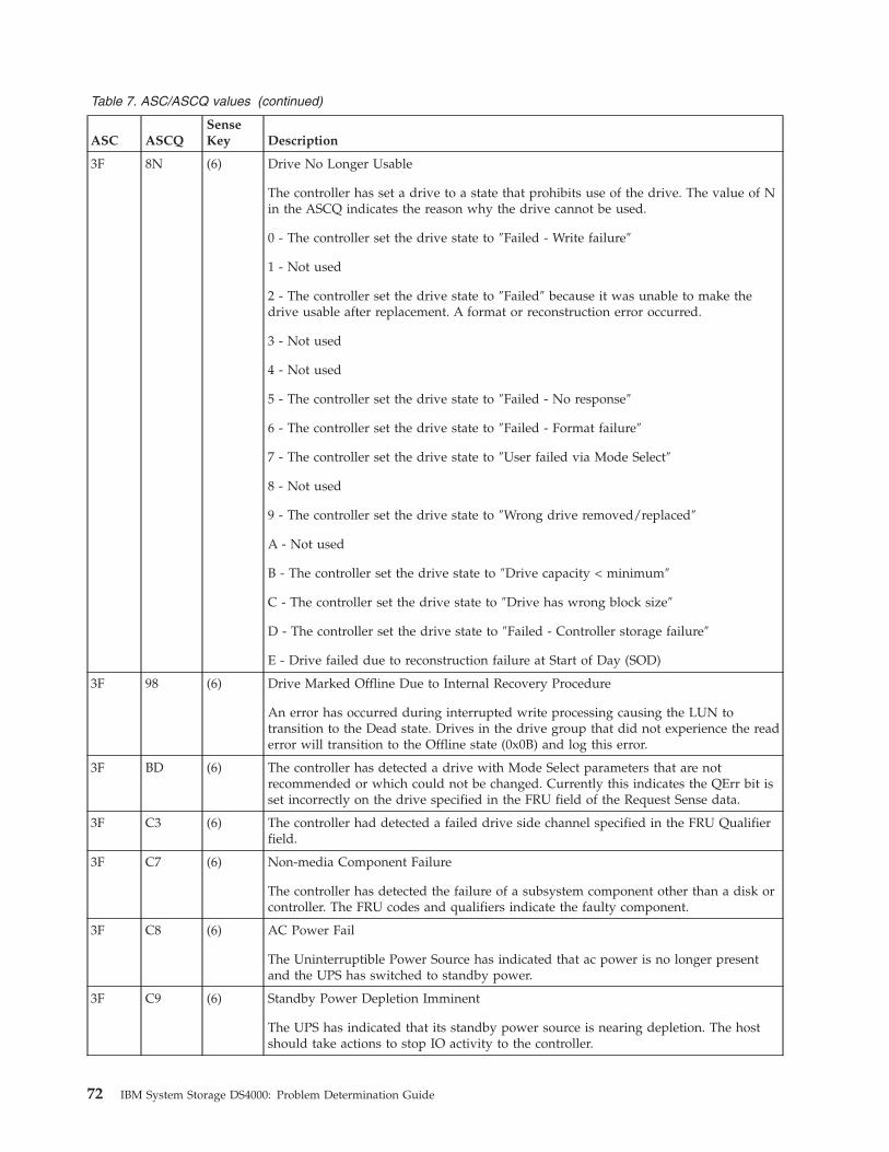
Table 7. ASC/ASCQ values (continued)
ASC ASCQ
Sense
Key Description
3F 8N (6) Drive No Longer Usable
The controller has set a drive to a state that prohibits use of the drive. The value of N
in the ASCQ indicates the reason why the drive cannot be used.
0 - The controller set the drive state to ″Failed - Write failure″
1 - Not used
2 - The controller set the drive state to ″Failed″ because it was unable to make the
drive usable after replacement. A format or reconstruction error occurred.
3 - Not used
4 - Not used
5 - The controller set the drive state to ″Failed - No response″
6 - The controller set the drive state to ″Failed - Format failure″
7 - The controller set the drive state to ″User failed via Mode Select″
8 - Not used
9 - The controller set the drive state to ″Wrong drive removed/replaced″
A - Not used
B - The controller set the drive state to ″Drive capacity < minimum″
C - The controller set the drive state to ″Drive has wrong block size″
D - The controller set the drive state to ″Failed - Controller storage failure″
E - Drive failed due to reconstruction failure at Start of Day (SOD)
3F 98 (6) Drive Marked Offline Due to Internal Recovery Procedure
An error has occurred during interrupted write processing causing the LUN to
transition to the Dead state. Drives in the drive group that did not experience the read
error will transition to the Offline state (0x0B) and log this error.
3F BD (6) The controller has detected a drive with Mode Select parameters that are not
recommended or which could not be changed. Currently this indicates the QErr bit is
set incorrectly on the drive specified in the FRU field of the Request Sense data.
3F C3 (6) The controller had detected a failed drive side channel specified in the FRU Qualifier
field.
3F C7 (6) Non-media Component Failure
The controller has detected the failure of a subsystem component other than a disk or
controller. The FRU codes and qualifiers indicate the faulty component.
3F C8 (6) AC Power Fail
The Uninterruptible Power Source has indicated that ac power is no longer present
and the UPS has switched to standby power.
3F C9 (6) Standby Power Depletion Imminent
The UPS has indicated that its standby power source is nearing depletion. The host
should take actions to stop IO activity to the controller.
72 IBM System Storage DS4000: Problem Determination Guide

Table 7. ASC/ASCQ values (continued)
ASC ASCQ
Sense
Key Description
3F CA (6) Standby Power Source Not at Full Capability
The UPS has indicated that its standby power source is not at full capacity.
3F CB (6) AC Power Has Been Restored
The UPS has indicated that ac power is now being used to supply power to the
controller.
3F D0 (6) Write Back Cache Battery Has Been Discharged
The controllers battery management has indicated that the cache battery has been
discharged.
3F D1 (6) Write Back Cache Battery Charge Has Completed
The controllers battery management has indicated that the cache battery is
operational.
3F D8 (6) Cache Battery Life Expiration
The cache battery has reached the specified expiration age.
3F D9 (6) Cache Battery Life Expiration Warning
The cache battery is within the specified number of weeks of failing.
3F E0 (6) Logical Unit Failure
The controller has placed the logical unit in a Dead state. User data, parity, or both
can no longer be maintained to ensure availability. The most likely cause is the failure
of a single drive in non-redundant configurations or a second drive in a configuration
protected by one drive. The data on the logical unit is no longer accessible.
3F EB (6) LUN marked Dead due to Media Error Failure during SOD
An error has occurred during interrupted write processing causing the LUN to
transition to the Dead state.
Chapter 6. PD hints: RAID controller errors in the Windows 2000, Windows 2003, or Windows NT event log 73
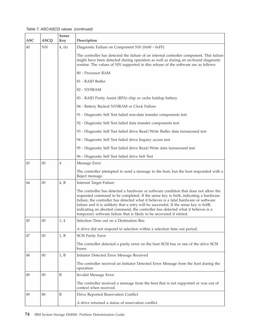
Table 7. ASC/ASCQ values (continued)
ASC ASCQ
Sense
Key Description
40 NN 4, (6) Diagnostic Failure on Component NN (0x80 - 0xFF)
The controller has detected the failure of an internal controller component. This failure
might have been detected during operation as well as during an on-board diagnostic
routine. The values of NN supported in this release of the software are as follows:
80 - Processor RAM
81 - RAID Buffer
82 - NVSRAM
83 - RAID Parity Assist (RPA) chip or cache holdup battery
84 - Battery Backed NVSRAM or Clock Failure
91 - Diagnostic Self Test failed non-data transfer components test
92 - Diagnostic Self Test failed data transfer components test
93 - Diagnostic Self Test failed drive Read/Write Buffer data turnaround test
94 - Diagnostic Self Test failed drive Inquiry access test
95 - Diagnostic Self Test failed drive Read/Write data turnaround test
96 - Diagnostic Self Test failed drive Self Test
43 00 4 Message Error
The controller attempted to send a message to the host, but the host responded with a
Reject message.
44 00 4, B Internal Target Failure
The controller has detected a hardware or software condition that does not allow the
requested command to be completed. If the sense key is 0x04, indicating a hardware
failure, the controller has detected what it believes is a fatal hardware or software
failure and it is unlikely that a retry will be successful. If the sense key is 0x0B,
indicating an aborted command, the controller has detected what it believes is a
temporary software failure that is likely to be recovered if retried.
45 00 1, 4 Selection Time out on a Destination Bus
A drive did not respond to selection within a selection time out period.
47 00 1, B SCSI Parity Error
The controller detected a parity error on the host SCSI bus or one of the drive SCSI
buses.
48 00 1, B Initiator Detected Error Message Received
The controller received an Initiator Detected Error Message from the host during the
operation.
49 00 B Invalid Message Error
The controller received a message from the host that is not supported or was out of
context when received.
49 80 B Drive Reported Reservation Conflict
A drive returned a status of reservation conflict.
74 IBM System Storage DS4000: Problem Determination Guide
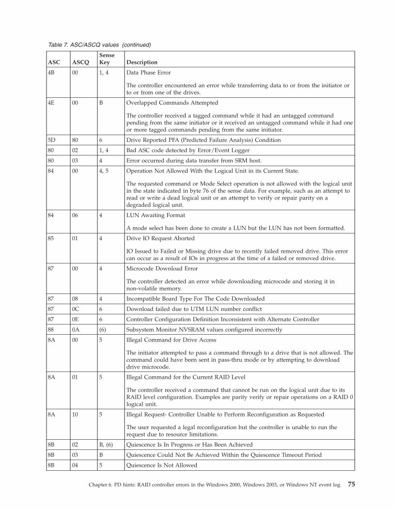
Table 7. ASC/ASCQ values (continued)
ASC ASCQ
Sense
Key Description
4B 00 1, 4 Data Phase Error
The controller encountered an error while transferring data to or from the initiator or
to or from one of the drives.
4E 00 B Overlapped Commands Attempted
The controller received a tagged command while it had an untagged command
pending from the same initiator or it received an untagged command while it had one
or more tagged commands pending from the same initiator.
5D 80 6 Drive Reported PFA (Predicted Failure Analysis) Condition
80 02 1, 4 Bad ASC code detected by Error/Event Logger
80 03 4 Error occurred during data transfer from SRM host.
84 00 4, 5 Operation Not Allowed With the Logical Unit in its Current State.
The requested command or Mode Select operation is not allowed with the logical unit
in the state indicated in byte 76 of the sense data. For example, such as an attempt to
read or write a dead logical unit or an attempt to verify or repair parity on a
degraded logical unit.
84 06 4 LUN Awaiting Format
A mode select has been done to create a LUN but the LUN has not been formatted.
85 01 4 Drive IO Request Aborted
IO Issued to Failed or Missing drive due to recently failed removed drive. This error
can occur as a result of IOs in progress at the time of a failed or removed drive.
87 00 4 Microcode Download Error
The controller detected an error while downloading microcode and storing it in
non-volatile memory.
87 08 4 Incompatible Board Type For The Code Downloaded
87 0C 6 Download failed due to UTM LUN number conflict
87 0E 6 Controller Configuration Definition Inconsistent with Alternate Controller
88 0A (6) Subsystem Monitor NVSRAM values configured incorrectly
8A 00 5 Illegal Command for Drive Access
The initiator attempted to pass a command through to a drive that is not allowed. The
command could have been sent in pass-thru mode or by attempting to download
drive microcode.
8A 01 5 Illegal Command for the Current RAID Level
The controller received a command that cannot be run on the logical unit due to its
RAID level configuration. Examples are parity verify or repair operations on a RAID 0
logical unit.
8A 10 5 Illegal Request- Controller Unable to Perform Reconfiguration as Requested
The user requested a legal reconfiguration but the controller is unable to run the
request due to resource limitations.
8B 02 B, (6) Quiescence Is In Progress or Has Been Achieved
8B 03 B Quiescence Could Not Be Achieved Within the Quiescence Timeout Period
8B 04 5 Quiescence Is Not Allowed
Chapter 6. PD hints: RAID controller errors in the Windows 2000, Windows 2003, or Windows NT event log 75

Table 7. ASC/ASCQ values (continued)
ASC ASCQ
Sense
Key Description
8E 01 E, (6) A Parity/Data Mismatch was Detected
The controller detected inconsistent parity/data during a parity verification.
91 00 5 General Mode Select Error
An error was encountered while processing a Mode Select command.
91 03 5 Illegal Operation for Current Drive State
A drive operation was requested through a Mode Select that cannot be run due to the
state of the drive. For example, a Delete Drive when the drive is part of a LUN.
91 09 5 Illegal Operation with Multiple SubLUNs Defined
An operation was requested that cannot be run when multiple SubLUNs are defined
on the drive.
91 33 5 Illegal Operation for Controller State
The requested Mode Select operation could not be completed due to the current state
of the controller.
91 36 5 Command Lock Violation
The controller received a Write Buffer Download Microcode, Send Diagnostic, or
Mode Select command, but only one such command is allowed at a time and there
was another such command active.
91 3B 6 Improper LUN Definition for Auto-Volume Transfer mode - AVT is disabled.
Controller will operate in normal redundant controller mode without performing
Auto-Volume transfers.
91 50 5 Illegal Operation For Drive Group State
An operation was requested that cannot be run due to the current state of the Drive
Group.
91 51 5 Illegal Reconfiguration Request - Legacy Constraint
Command could not be completed due to Legacy configuration or definition
constraints.
91 53 5 Illegal Reconfiguration Request - System Resource Constraint
Command could not be completed due to resource limitations of the controller.
94 01 5 Invalid Request Due to Current Logical Unit Ownership
95 01 4 Extended Drive Insertion/Removal Signal
The controller has detected the drive insertion/removal signal permanently active.
95 02 (6) Controller Removal/Replacement Detected or Alternate Controller Released from
Reset
The controller detected the activation of the signal or signals used to indicate that the
alternate controller has been removed or replaced.
98 01 (6) The controller has determined that there are multiple sub-enclosures with the same ID
value selected.
98 02 (6) Sub-enclosure with redundant ESMs specifying different Tray IDs
98 03 (6) Sub-enclosure ESMs have different firmware levels
76 IBM System Storage DS4000: Problem Determination Guide

Table 7. ASC/ASCQ values (continued)
ASC ASCQ
Sense
Key Description
A0 00 (6) Write Back Caching Could Not Be Enabled
The controller could not perform write-back caching due to a battery failure or
discharge, Two Minute Warning signal from the UPS, or an ICON failure.
A1 00 (6) Write Back Caching Could Not Be Enabled - RDAC Cache Size Mismatch
The controller could not perform write back caching due to the cache sizes of the two
controllers in the RDAC pair not matching.
A4 00 (6) Global Hot Spare Size Insufficient for All Drives in Subsystem.
A defined Global Hot Spare is not large enough to cover all of the drives present in
the subsystem. Failure of a drive larger than the Global Hot Spare will not be covered
by the Global Hot Spare drive.
A6 00 (6) Recovered processor memory failure
The controller has detected and corrected a recoverable error in processor memory.
A7 00 (6) Recovered data buffer memory error
The controller has detected and corrected a recoverable error in the data buffer
memory.
Sense bytes 34-36 will contain the count of errors encountered and recovered.
C0 00 4, (6) The Inter-controller Communications Have Failed
The controller has detected the failure of the communications link between redundant
controllers.
D0 06 4 Drive IO time out
The controller destination IO timer expired while waiting for a drive command to
complete.
D1 0A 4 Drive Reported Busy Status
A drive returned a busy status in response to a command.
E0 XX 4 Destination Channel Error
XX = 00 through 07 indicates the Sense Key returned by the drive after a check
condition status
XX = 10 indicates that a bus level error occurred
E0 XX 6 Fibre Channel Destination Channel Error
XX = 20 indicates redundant path is not available to devices
XX = 21 indicates destination drive channels are connected to each other
Sense Byte 26 will contain the Tray ID.
Sense Byte 27 will contain the Channel ID.
Chapter 6. PD hints: RAID controller errors in the Windows 2000, Windows 2003, or Windows NT event log 77
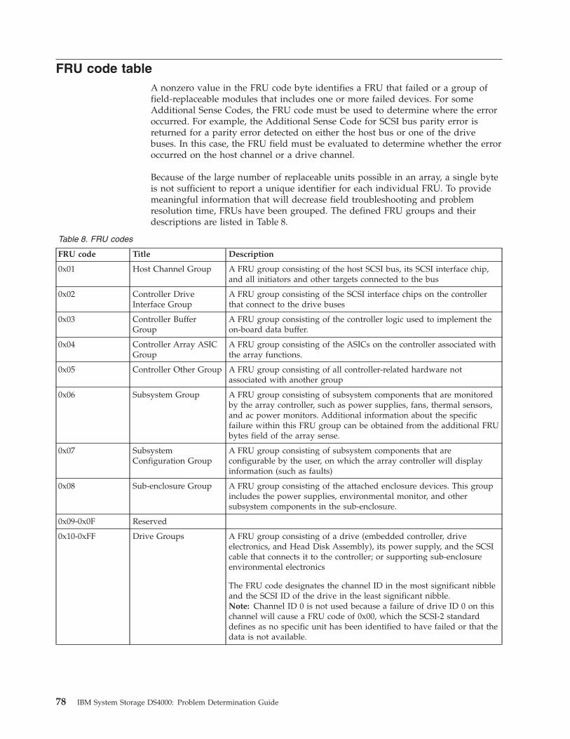
FRU code table
A nonzero value in the FRU code byte identifies a FRU that failed or a group of
field-replaceable modules that includes one or more failed devices. For some
Additional Sense Codes, the FRU code must be used to determine where the error
occurred. For example, the Additional Sense Code for SCSI bus parity error is
returned for a parity error detected on either the host bus or one of the drive
buses. In this case, the FRU field must be evaluated to determine whether the error
occurred on the host channel or a drive channel.
Because of the large number of replaceable units possible in an array, a single byte
is not sufficient to report a unique identifier for each individual FRU. To provide
meaningful information that will decrease field troubleshooting and problem
resolution time, FRUs have been grouped. The defined FRU groups and their
descriptions are listed in Table 8.
Table 8. FRU codes
FRU code Title Description
0x01 Host Channel Group A FRU group consisting of the host SCSI bus, its SCSI interface chip,
and all initiators and other targets connected to the bus
0x02 Controller Drive
Interface Group
A FRU group consisting of the SCSI interface chips on the controller
that connect to the drive buses
0x03 Controller Buffer
Group
A FRU group consisting of the controller logic used to implement the
on-board data buffer.
0x04 Controller Array ASIC
Group
A FRU group consisting of the ASICs on the controller associated with
the array functions.
0x05 Controller Other Group A FRU group consisting of all controller-related hardware not
associated with another group
0x06 Subsystem Group A FRU group consisting of subsystem components that are monitored
by the array controller, such as power supplies, fans, thermal sensors,
and ac power monitors. Additional information about the specific
failure within this FRU group can be obtained from the additional FRU
bytes field of the array sense.
0x07 Subsystem
Configuration Group
A FRU group consisting of subsystem components that are
configurable by the user, on which the array controller will display
information (such as faults)
0x08 Sub-enclosure Group A FRU group consisting of the attached enclosure devices. This group
includes the power supplies, environmental monitor, and other
subsystem components in the sub-enclosure.
0x09-0x0F Reserved
0x10-0xFF Drive Groups A FRU group consisting of a drive (embedded controller, drive
electronics, and Head Disk Assembly), its power supply, and the SCSI
cable that connects it to the controller; or supporting sub-enclosure
environmental electronics
The FRU code designates the channel ID in the most significant nibble
and the SCSI ID of the drive in the least significant nibble.
Note: Channel ID 0 is not used because a failure of drive ID 0 on this
channel will cause a FRU code of 0x00, which the SCSI-2 standard
defines as no specific unit has been identified to have failed or that the
data is not available.
78 IBM System Storage DS4000: Problem Determination Guide

Chapter 7. PD hints: Configuration types
You should be referred to this chapter from a PD map or indication. If this is not
the case, see Chapter 2, “Problem determination starting points,” on page 3.
After you read the relevant information in this chapter, return to the
“Configuration Type PD map” on page 8.
To simplify a complicated configuration so that it can be debugged readily, reduce
the configuration to subsets that you can use to build the larger configuration. This
process yields two basic configurations. (The type of RAID controller is not
material; DS4800 is shown in the following examples.) The following two sections
discuss these two basic configurations.
Type 1 configuration
The identifying features of a type 1 configuration (as shown in Figure 24) are:
v Host adapters are connected directly to mini-hubs of Controller A and B, with
one or more host adapters per system.
v Multiple servers can be connected, but without system-to-system failover (no
cluster).
v Uses some type of isolation mechanism (such as partitions) between server
resources.
Table 9. Description of Figure 24
Number Description
�1� FC host adapter (HBA)
�2� Single path(s)—adapter to controller
�3� DS4800 controller A
�4� DS4800 controller B
Figure 24. Type 1 configuration
© Copyright IBM Corp. 2006 79

80 IBM System Storage DS4000: Problem Determination Guide

Type 2 configuration
The type 2 configuration can occur with or without hubs and switches, as shown
in Figure 25 and Figure 26 on page 82.
Table 10. Description of Figure 25
Number Description
�1� FC host adapter (HBA)
�2� Managed switch
�3� DS4800 controller A
�4� DS4800 controller B
The identifying features of a type 2 configuration are:
v Multiple host adapters are connected for full redundancy across systems having
failover support such as MSCS.
v Host adapters are connected either directly to mini-hubs or through managed
hubs or switches (2 GBIC ports per mini-hub are possible).
v A redundant path to mini-hubs can be separated using optional mini-hubs, as
shown in the following figure in red (versus the green path).
Figure 25. Type 2 configuration—with switches
Chapter 7. PD hints: Configuration types 81
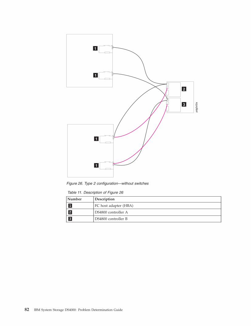
Table 11. Description of Figure 26
Number Description
�1� FC host adapter (HBA)
�2� DS4800 controller A
�3� DS4800 controller B
Figure 26. Type 2 configuration—without switches
82 IBM System Storage DS4000: Problem Determination Guide
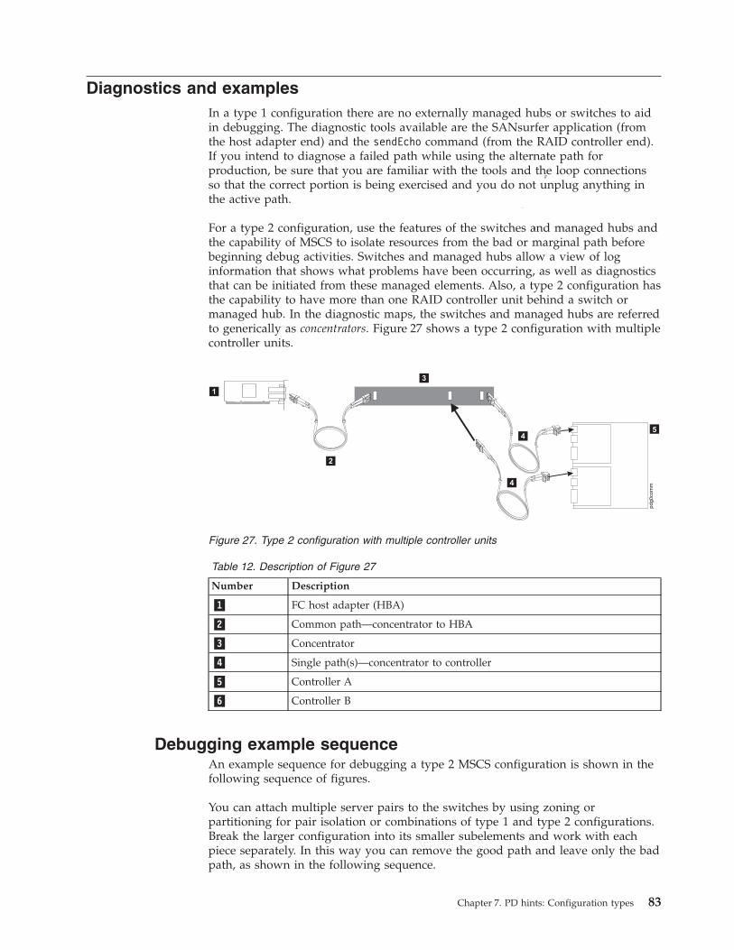
Diagnostics and examples
In a type 1 configuration there are no externally managed hubs or switches to aid
in debugging. The diagnostic tools available are the SANsurfer application (from
the host adapter end) and the sendEcho command (from the RAID controller end).
If you intend to diagnose a failed path while using the alternate path for
production, be sure that you are familiar with the tools and the loop connections
so that the correct portion is being exercised and you do not unplug anything in
the active path.
For a type 2 configuration, use the features of the switches and managed hubs and
the capability of MSCS to isolate resources from the bad or marginal path before
beginning debug activities. Switches and managed hubs allow a view of log
information that shows what problems have been occurring, as well as diagnostics
that can be initiated from these managed elements. Also, a type 2 configuration has
the capability to have more than one RAID controller unit behind a switch or
managed hub. In the diagnostic maps, the switches and managed hubs are referred
to generically as concentrators. Figure 27 shows a type 2 configuration with multiple
controller units.
Table 12. Description of Figure 27
Number Description
�1� FC host adapter (HBA)
�2� Common path—concentrator to HBA
�3� Concentrator
�4� Single path(s)—concentrator to controller
�5� Controller A
�6� Controller B
Debugging example sequence
An example sequence for debugging a type 2 MSCS configuration is shown in the
following sequence of figures.
You can attach multiple server pairs to the switches by using zoning or
partitioning for pair isolation or combinations of type 1 and type 2 configurations.
Break the larger configuration into its smaller subelements and work with each
piece separately. In this way you can remove the good path and leave only the bad
path, as shown in the following sequence.
Figure 27. Type 2 configuration with multiple controller units
Chapter 7. PD hints: Configuration types 83
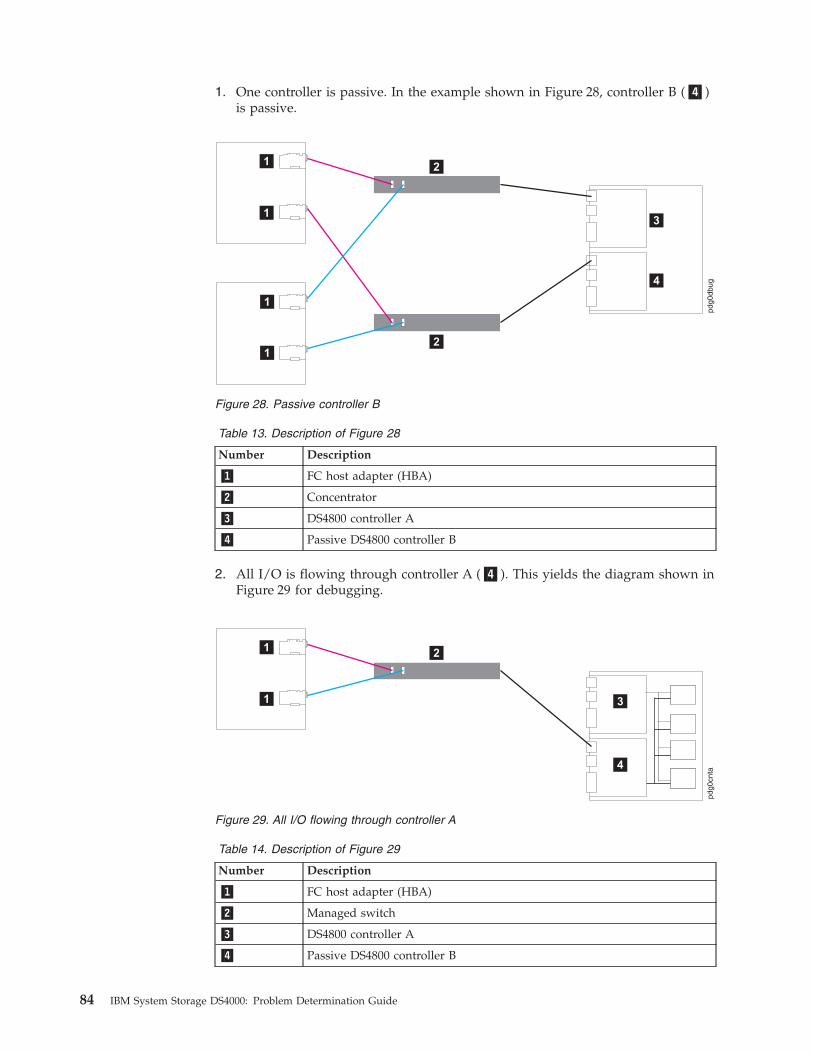
1. One controller is passive. In the example shown in Figure 28, controller B (�4�)
is passive.
Table 13. Description of Figure 28
Number Description
�1� FC host adapter (HBA)
�2� Concentrator
�3� DS4800 controller A
�4� Passive DS4800 controller B
2. All I/O is flowing through controller A (�4�). This yields the diagram shown in
Figure 29 for debugging.
Table 14. Description of Figure 29
Number Description
�1� FC host adapter (HBA)
�2� Managed switch
�3� DS4800 controller A
�4� Passive DS4800 controller B
Figure 28. Passive controller B
Figure 29. All I/O flowing through controller A
84 IBM System Storage DS4000: Problem Determination Guide

3. To see more clearly what is involved, redraw the configuration showing the
path elements in the loop, as shown in Figure 30.
Table 15. Description of Figure 30
Number Description
�1� FC host adapter (HBA)
�2� Managed switch
�3� 2200 FC host adapter (HBA)
�4� SFP module
�5� DS4800 controller A
�6� Passive DS4800 controller B
Figure 30. Path elements loop
Chapter 7. PD hints: Configuration types 85

86 IBM System Storage DS4000: Problem Determination Guide
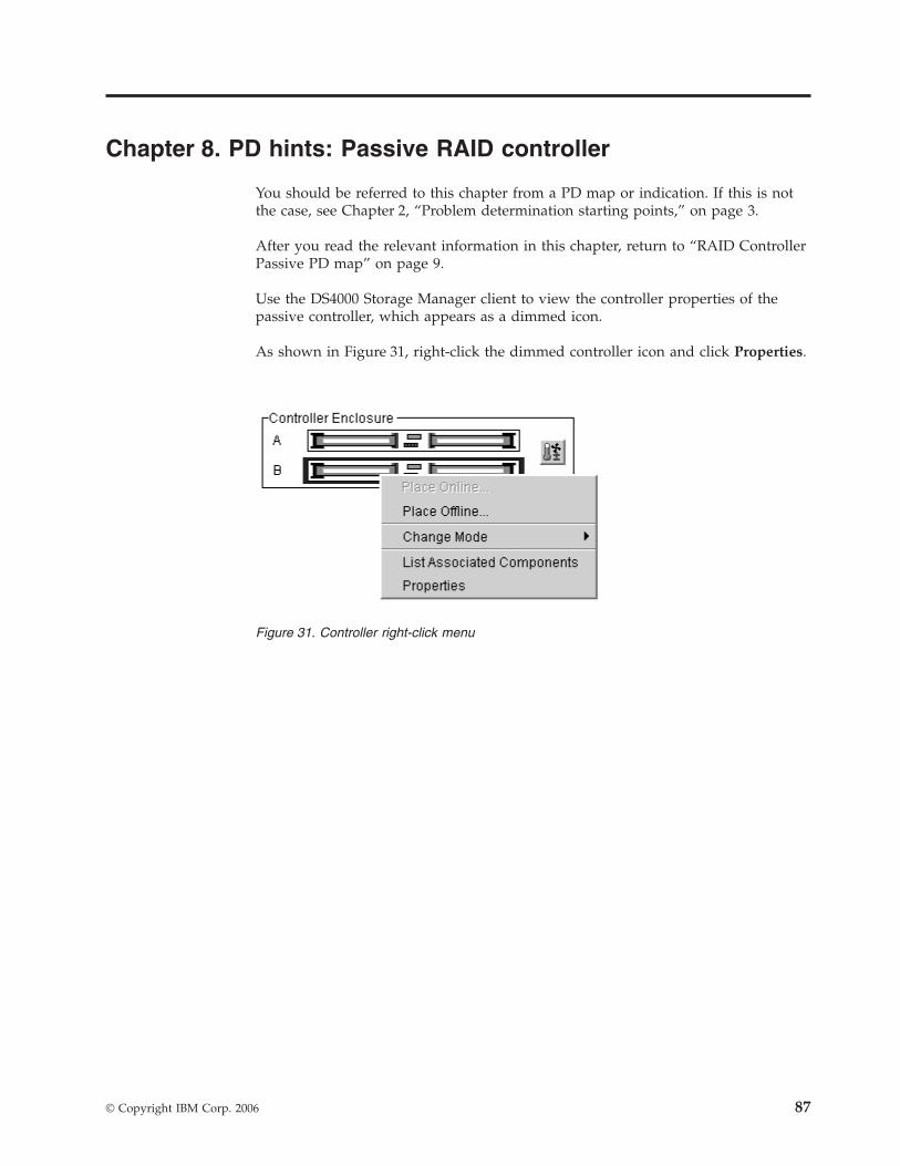
Chapter 8. PD hints: Passive RAID controller
You should be referred to this chapter from a PD map or indication. If this is not
the case, see Chapter 2, “Problem determination starting points,” on page 3.
After you read the relevant information in this chapter, return to “RAID Controller
Passive PD map” on page 9.
Use the DS4000 Storage Manager client to view the controller properties of the
passive controller, which appears as a dimmed icon.
As shown in Figure 31, right-click the dimmed controller icon and click Properties.
Figure 31. Controller right-click menu
© Copyright IBM Corp. 2006 87

If the Controller Properties view (shown in Figure 32) of the dimmed controller
icon does not include a message about it being cached, then the controller is
passive. Return to the PD map at the page that referred you here (“RAID
Controller Passive PD map” on page 9) and continue.
If the Controller Properties information cannot be retrieved, then call IBM Support.
Perform the following steps when you encounter a passive controller and want to
understand the cause:
1. Check the controller LEDs to verify that a controller is passive and to see
which controller is passive.
2. Look on the system event viewer of the server to find the SYMarray event ID
18. When you find it, write down the date, time, and SRB status. (The SRB
status is found in offset x3A in the Windows NT event log. For an example of
offset x3A, see the fourth row, third column of the figure on page 66.)
3. If multiple servers are involved, repeat step 2 for each server.
4. Look for the first event ID 18 found in step 2. The SRB status provides
information as to why the failure occurred but is valid only if the high order
bit is on (8x, 9x, Ax).
5. Check the history of the event log looking for the QL2200/QL2100 events.
These entries will give further clues as to whether the fibre loop was stable or
not.
v SRB statuses of 0x0d, 0x0e, and 0x0f point to an unstable loop. (To find the
value, discard the high order ″valid″ bit. For example, 8d yields an SRB
status of 0d.)
Figure 32. Controller Properties window
88 IBM System Storage DS4000: Problem Determination Guide

v QL2200/2100 events of 80110000, 80120000 indicate an unstable loop. 6. If an unstable loop is suspected, diagnose the loop using the fibre path PD
aids (see “Fibre Path PD map 1” on page 16).
7. If the diagnosis in step 6 does not reveal the problem, then the adapter and
the controller might be the cause. If you determine that the adapter and
controller caused the problem, then reset all fibre components on the path and
retest.
8. If fibre cabling can be rearranged, swap the adapter cabling so that the
adapter communicating to controller A is now connected to controller B (and
vice-versa).
Note: Do not do this in a system that is still being used for business. It is
useful for bring-up debug.
9. When the problem is resolved, set the controller back to active and rebalance
the logical drives.
10. If the problem occurred as the result of an I/O condition, then rerun and
determine whether the failure reoccurs.
Note: If the failure still occurs, then you need to perform further analysis,
including the use of the serial port to look at loop statuses. The previous
steps do not include consideration of switches or managed hubs. If these are
included, then see “Hub/Switch PD map 1” on page 13 for helpful tools.
Chapter 8. PD hints: Passive RAID controller 89

90 IBM System Storage DS4000: Problem Determination Guide

Chapter 9. PD hints: Performing sendEcho tests
You should arrive at this chapter from a PD map or indication. If this is not the
case, see Chapter 2, “Problem determination starting points,” on page 3.
After you read the relevant information in this chapter, return to “Single Path Fail
PD map 1” on page 18.
The 3526 RAID controllers use MIA copper-to-optical converters, while the
FAStT200, FAStT500, DS4400, DS4500, DS4300, DS4100, and DS4800 controllers use
GBICs or SFPs. There are times when these devices, and their corresponding cable
mediums, need to be tested to insure that they are functioning properly.
Note: Running the loopback test for a short period of time might not catch
intermittent problems. It might be necessary to run the test in a continuous
loop for at least several minutes to track down intermittent problems.
Setting up for a loopback test
This section describes how to set up for a loopback test.
Loopback test for MIA or mini-hub testing
Perform the following steps to set up a loopback test:
1. Remove the fiber-optic cable from the controller MIA or mini-hub.
2. Depending on whether you are working with a 3526 RAID controller or with a
FAStT500, DS4400, DS4500, DS4300, DS4100 or DS4800 RAID controller,
perform one of the following actions to set up a loopback test:
a. For a Type 3526 RAID controller, install a wrap plug to the MIA on
controller A. See Figure 33.
3526 Controller Unit
Failed path of read/write buffer test
Install wrap plug to MIA on controller A
CtrlA
Figure 33. Install wrap plug to MIA on controller A
© Copyright IBM Corp. 2006 91
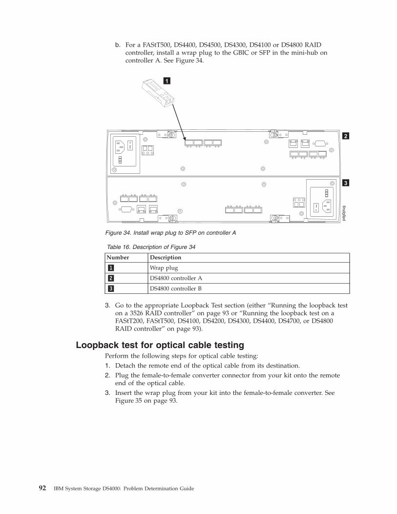
b. For a FAStT500, DS4400, DS4500, DS4300, DS4100 or DS4800 RAID
controller, install a wrap plug to the GBIC or SFP in the mini-hub on
controller A. See Figure 34.
Table 16. Description of Figure 34
Number Description
�1� Wrap plug
�2� DS4800 controller A
�3� DS4800 controller B
3. Go to the appropriate Loopback Test section (either “Running the loopback test
on a 3526 RAID controller” on page 93 or “Running the loopback test on a
FAStT200, FAStT500, DS4100, DS4200, DS4300, DS4400, DS4700, or DS4800
RAID controller” on page 93).
Loopback test for optical cable testing
Perform the following steps for optical cable testing:
1. Detach the remote end of the optical cable from its destination.
2. Plug the female-to-female converter connector from your kit onto the remote
end of the optical cable.
3. Insert the wrap plug from your kit into the female-to-female converter. See
Figure 35 on page 93.
Figure 34. Install wrap plug to SFP on controller A
92 IBM System Storage DS4000: Problem Determination Guide

Table 17. Description of Figure 35
Number Description
�1� Wrap plug
�2� FC cable
�3� Controller A
�4� Controller B
4. Go to the appropriate loopback test section (either “Running the loopback test
on a 3526 RAID controller” or “Running the loopback test on a FAStT200,
FAStT500, DS4100, DS4200, DS4300, DS4400, DS4700, or DS4800 RAID
controller”).
Running the loopback test on a 3526 RAID controller
Perform the following steps for a loopback test on a 3526 RAID controller:
1. In the controller shell, type the following command: fc 5
2. From the output, write down the AL_PA (Port_ID) for this controller.
3. Type the command
isp sendEcho,<AL_PA>,<# of iterations>
It is recommended that you use 50 000 for # of iterations. A value of -1 will
run for an infinite number of iterations. Message output to the controller shell
is generated for every 10 000 frames sent.
4. Type the command stopEcho when tests are complete.
Running the loopback test on a FAStT200, FAStT500, DS4100, DS4200,
DS4300, DS4400, DS4700, or DS4800 RAID controller
Perform the following steps for a loopback test on a FAStT200, FAStT500, DS4400,
DS4300, DS4100, or DS4800 RAID controller:
1. In the controller shell, type the following command: fcAll
2. From the output, write down the AL_PA (Port_ID) for the channel to be tested.
Figure 35. Install wrap plug
Chapter 9. PD hints: Performing sendEcho tests 93

3. Type the command fcChip=X where X=the chip number for the loop to be
tested.
4. Type the command
isp sendEcho,<AL_PA>,<# of iterations>
It is recommended that you use 50 000 for # of iterations. A value of -1 will
run for an infinite number of iterations. Message output to the controller shell
is generated for every 10 000 frames sent.
5. Type the command stopEcho when tests are complete.
If the test is successful, you will receive the following message:
Echo accept (count n)
If you receive the following message:
Echo timeout interrupt: interrupt ... end echo test
or if you receive nonzero values after entering the command isp sendEcho, then
there is still a problem. Continue with the “Single Path Fail PD map 1” on page 18.
94 IBM System Storage DS4000: Problem Determination Guide

Chapter 10. PD hints: Tool hints
You should be referred to this chapter from a PD map or indication. If this is not
the case, refer back to Chapter 2, “Problem determination starting points,” on page
3.
This chapter contains the following tool hints:
v “Determining the configuration”
v “Start delay” on page 97
v “Connectors and locations” on page 99
v “Controller diagnostics” on page 105
v “Linux port configuration” on page 106
Determining the configuration
Use the SANsurfer application to determine what host adapters are present and
where they are in the systems, as well as what RAID controllers are attached and
whether they are on Fabric (switches) or loops. Alternately, you can click Control
Panel -> SCSI adapters in Windows NT or Control Panel -> System -> Hardware
-> Device Manager -> SCSI and RAID Controllers in Windows 2000.
Figure 36 shows the SANsurfer window for a configuration with two 2200 host
adapters. When only the last byte of the Port ID is displayed, this indicates that
the connection is an arbitrated loop.
A different configuration is shown in Figure 37 on page 96, which shows a 2200
adapter. Its WWN is 20-00-00-E0-8B-04-A1-30, and it has five devices attached to it.
Figure 36. SANsurfer window—Two 2200 host adapters
© Copyright IBM Corp. 2006 95

When the first two bytes of the Port ID display (and they are other than 00), the
configuration is Fabric (switch).
As shown in Figure 38, if you select one of the devices beneath a host adapter, you
find that it is a controller in a 3526 RAID controller unit.
Figure 37. SANsurfer window—One 2200 host adapter
Figure 38. 3526 controller information
96 IBM System Storage DS4000: Problem Determination Guide

Start delay
In Windows operating systems, an extended startup delay indicates that the
Windows system cannot find the configuration that is in the Windows registry. In
Linux operating systems, the delay also might be caused by an incorrectly
configured storage subsystem (see “Linux port configuration” on page 106 for hints
on troubleshooting this problem.)
The startup delay in the Windows operating system can be caused by several
things, but the following example shows what typically happens when a fibre
channel cable connecting a host adapter to the storage fails (a failed cable is broken
so that no light makes it through the cable).
Note: The screen, containing white text on a blue background, that appears when
a Microsoft Windows operating system locks up, is referred to as the blue
screen. The following blue-screen example describes startup delay symptoms
in a Windows NT operating system. In the Windows 2000 operating system,
the Starting Up progress bar will freeze. To retrieve the SCSI information in
Windows 2000, open the Computer Management window (right-click My
Computer, and then select Manage.)
1. Windows NT displays the blue screen and reports the first two lines (version,
number of processors, and amount of memory). Windows NT takes a long time
to start. The SCSI Adapters applet in the Control Panel opens the SCSI
Adapters window shown in Figure 39 for the 2100.
There are no other devices; there should be a Bus 0 with 21 of the IBM 3526s
and one IBM Universal Xport. The 2100 DD shows as started in the Drivers
page and in the Control Panel Devices applet.
Figure 39. SCSI adapters
Chapter 10. PD hints: Tool hints 97

2. WINDISK is started. It takes longer than normal to start (and there is a
particularly long pause at the 100% mark), and then displays the message
shown in Figure 40.
3. Because the disks were balanced across the two RAID controllers before the
error occurred, every other disk shows in the Disk Administrator as offline, and
the partition information section is not available, the following message is
displayed:
Configuration information not available
The drive letters do not change for the drives. The drive letters are sticky (do
not change), even though they are set only for the boot drive (drive that contains
the operating system and is used to start the computer). Because the cable to
RAID controller A is the failed cable, it is Disk 0, Disk 2, and so on, that are
missing. See Figure 41.
4. If Done: Return to “Start Delay PD map” on page 11.
Figure 40. Disk Administrator information window
Figure 41. Disk Administrator
98 IBM System Storage DS4000: Problem Determination Guide
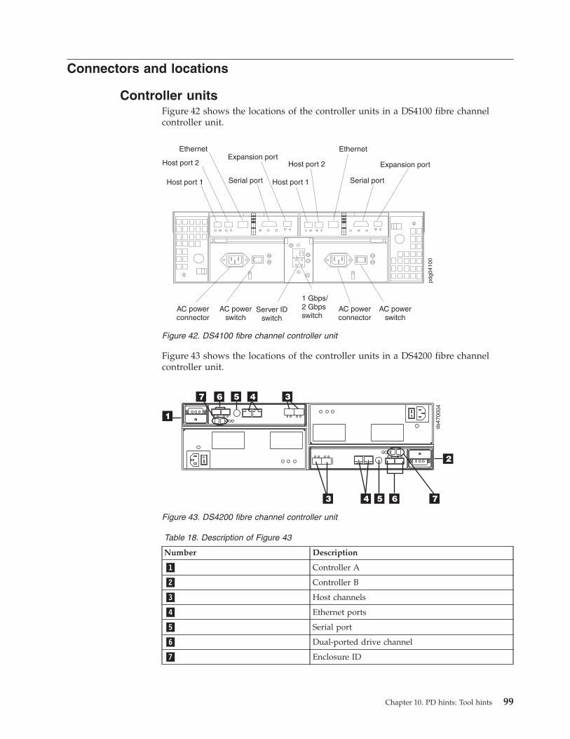
Connectors and locations
Controller units
Figure 42 shows the locations of the controller units in a DS4100 fibre channel
controller unit.
Figure 43 shows the locations of the controller units in a DS4200 fibre channel
controller unit.
Table 18. Description of Figure 43
Number Description
�1� Controller A
�2� Controller B
�3� Host channels
�4� Ethernet ports
�5� Serial port
�6� Dual-ported drive channel
�7� Enclosure ID
Figure 42. DS4100 fibre channel controller unit
ds47
0004
34567
2
3 4 5 6
1
7
Figure 43. DS4200 fibre channel controller unit
Chapter 10. PD hints: Tool hints 99

Figure 44 shows the locations of the controller units in a DS4300 fibre channel
controller unit.
Figure 45 shows the locations of the controller units in a DS4400 and DS4500 fibre
channel controller unit.
Figure 46 shows the locations of the controller units in a DS4700 fibre channel
controller unit.
Figure 44. DS4300 fibre channel controller unit
Figure 45. DS4400 / DS4500 fibre channel controller unit
ds47
0014
2
3456
1
8 7
3 4 5 6 87
Figure 46. DS4700 fibre channel controller unit
100 IBM System Storage DS4000: Problem Determination Guide

Table 19. Description of Figure 46
Number Description
�1� Controller A
�2� Controller B
�3� Drive Channel 1 - Port 2 on Controller A
Drive Channel 2 - Port 2 on Controller B
�4� Drive Channel 1 - Port 1 on Controller A
Drive Channel 2 - Port 1 on Controller B
�5� Host Port 4
�6� Host Port 3
�7� Host Port 2
�8� Host Port 1
Figure 47 shows the locations of the controller units in a DS4800 fibre channel
controller unit.
Figure 48 on page 102 shows the locations of the controller connections in a
FAStT500 or DS4400 fibre channel controller unit.
Note: In Figure 48 on page 102, a FAStT500 controller unit is shown.
Figure 47. DS4800 fibre channel controller unit
Chapter 10. PD hints: Tool hints 101
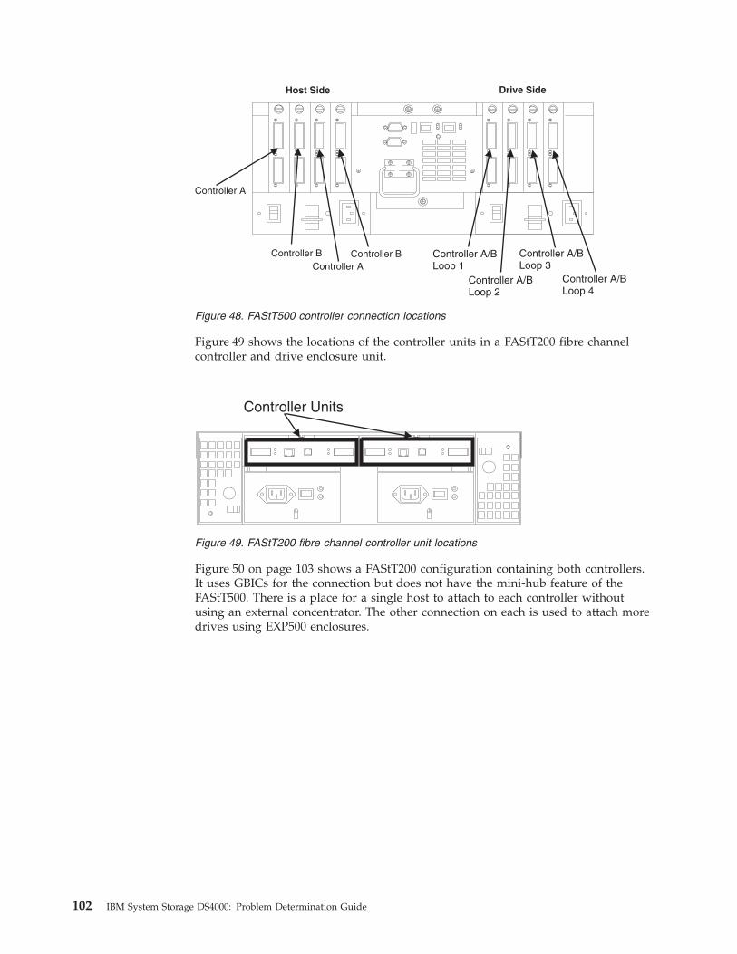
Figure 49 shows the locations of the controller units in a FAStT200 fibre channel
controller and drive enclosure unit.
Figure 50 on page 103 shows a FAStT200 configuration containing both controllers.
It uses GBICs for the connection but does not have the mini-hub feature of the
FAStT500. There is a place for a single host to attach to each controller without
using an external concentrator. The other connection on each is used to attach more
drives using EXP500 enclosures.
Host Side Drive Side
Controller B Controller B Controller A/BLoop 1
Controller A/BLoop 2
Controller A/BLoop 3
Controller A/BLoop 4
Controller A
Controller A
Figure 48. FAStT500 controller connection locations
Controller Units
Figure 49. FAStT200 fibre channel controller unit locations
102 IBM System Storage DS4000: Problem Determination Guide
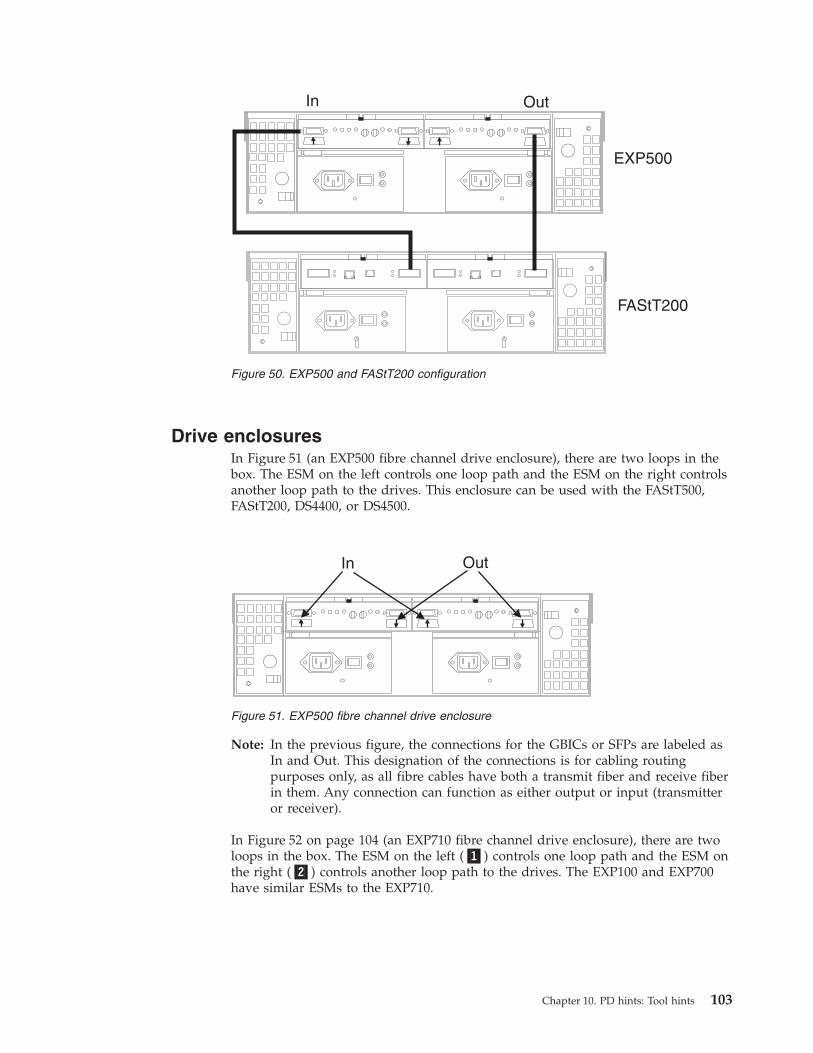
Drive enclosures
In Figure 51 (an EXP500 fibre channel drive enclosure), there are two loops in the
box. The ESM on the left controls one loop path and the ESM on the right controls
another loop path to the drives. This enclosure can be used with the FAStT500,
FAStT200, DS4400, or DS4500.
Note: In the previous figure, the connections for the GBICs or SFPs are labeled as
In and Out. This designation of the connections is for cabling routing
purposes only, as all fibre cables have both a transmit fiber and receive fiber
in them. Any connection can function as either output or input (transmitter
or receiver).
In Figure 52 on page 104 (an EXP710 fibre channel drive enclosure), there are two
loops in the box. The ESM on the left (�1�) controls one loop path and the ESM on
the right (�2�) controls another loop path to the drives. The EXP100 and EXP700
have similar ESMs to the EXP710.
In Out
FAStT200
EXP500
Figure 50. EXP500 and FAStT200 configuration
In Out
Figure 51. EXP500 fibre channel drive enclosure
Chapter 10. PD hints: Tool hints 103
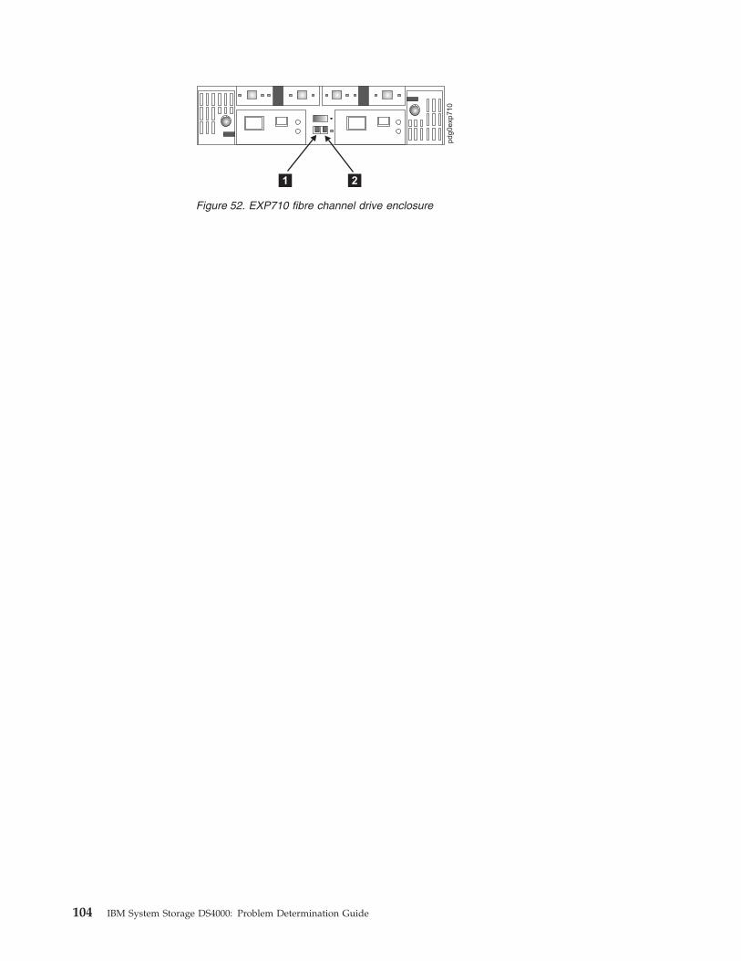
Figure 52. EXP710 fibre channel drive enclosure
104 IBM System Storage DS4000: Problem Determination Guide

Controller diagnostics
The DS4000 Storage Manager Diagnostics option enables a user to verify that a
controller is functioning properly, using various internal tests. One controller is
designated as the Controller Initiating the Test (CIT). The other controller is the
Controller Under Test (CUT).
The diagnostics use a combination of three different tests: Read Test, Write Test,
and Data Loopback Test. You should run all three tests at initial installation and
any time there are changes to the storage subsystem or components that are
connected to the storage subsystem (such as hubs, switches, and host adapters).
Note: During the diagnostics, the controller on which the tests are run (CUT) will
NOT be available for I/O.
v Read Test
The Read Test initiates a read command as it would be sent over an I/O data
path. It compares data with a known, specific data pattern, checking for data
integrity and redundancy errors. If the read command is unsuccessful or the
data compared is not correct, the controller is considered to be in error and is
failed.
v Write Test
A Write Test initiates a write command as it would be sent over an I/O data
path (to the Diagnostics region on a specified drive). This Diagnostics region is
then read and compared to a specific data pattern. If the write fails or the data
compared is not correct, the controller is considered to be in error and is failed
and placed offline. (Use the Recovery Guru to replace the controller.)
v Data Loopback Test
Important: The Data Loopback Test does not run on controllers that have SCSI
connections between the RAID controllers and drive (model 3526).
The Data Loopback Test is run only on controllers that have fibre channel
connections between the controller and the drives. The test passes data through
each controller’s drive-side channel, mini-hub, out onto the loop and then back
again. Enough data is transferred to determine error conditions on the channel.
If the test fails on any channel, then this status is saved so that it can be
returned if all other tests pass.
All test results display in the status area of the Diagnostics window.
Events are written to the DS4000 Storage Manager Event Log when diagnostics is
started, and when it is has completed testing. These events will help you to
evaluate whether diagnostics testing was successful or failed, and the reason for
the failure. To view the Event Log, click View -> Event Log in the Subsystem
Management Window.
Running controller diagnostics
Important: If diagnostics are run while a host is using the logical drives owned by
the selected controller, the I/O directed to this controller path is rejected.
Perform the following steps to run various internal tests to verify that a controller
is functioning properly.
1.
a. For FAStT200 and FAStT500 subsystems, in the Subsystem Management
Window, highlight a controller. Then, either click Controller -> Run
Chapter 10. PD hints: Tool hints 105
Diagnostics from the main menu or right-click the controller and click Run
Diagnostics from the menu. The Diagnostics window opens.
b. For DS4400, DS4500, DS4300, DS4100, and DS4800, from the Subsystem
Management Window, highlight a controller. Click Advanced ->
Troubleshooting -> Run Diagnostics from the main menu. The Diagnostics
window opens.2. Select the check boxes for the diagnostic tests to be run. Choose from the
following list:
v Read Test
v Write Test
v Data Loopback Test3. To run the Data Loopback Test on a single channel, select a channel from the
drop-down list.
4. Select a Data Pattern file for the Data Loopback Test. Select Use Default Data
Pattern to use the default Data Pattern or Use Custom Data Pattern file to
specify another file.
Note: A custom Data Pattern file called diagnosticsDataPattern.dpf is provided
on the root directory of the Storage Manager folder. This file can be
modified, but the file must have the following properties to work
correctly for the test:
v The file values must be entered in hexadecimal format (00 to FF) with
one space ONLY between the values.
v The file must be no larger than 64 bytes in size. (Smaller files will
work but larger files will cause an error.)5. Click Run. The Run Diagnostics confirmation window opens.
6. Type yes in the confirmation field, and then click OK.
The selected diagnostic tests begin. When the tests are complete, the Status
field is updated with test results. The test results contain a generic, overall
status message, and a set of specific test results. Each test result contains the
following information:
v Test (Read/Write/Data Loopback)
v Port (Read/Write)
v Level (Internal/External)
v Status (Pass/Fail)7. Click Close to close the window.
Important: When diagnostics are completed, the controller should automatically
allow data to be transferred to it. However, if there is a situation where data
transfer is not re-enabled, highlight the controller and click Data Transfer ->
Enable.
Linux port configuration
Linux operating systems do not use the IBM DS4000 Storage Manager to configure
their associated Storage Subsystems. Instead, use the SANsurfer application to
perform Device and LUN configuration on Linux operating systems. However, the
DS4000 Storage Manager is used to map the DS4000 Storage Servers’ logical drives
to the appropriate operating system (in this case, Linux). The following sections
provide you with hints on how to correctly configure your storage for a Linux
system.
106 IBM System Storage DS4000: Problem Determination Guide
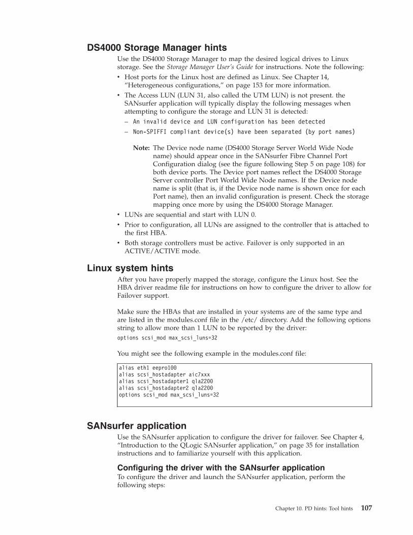
DS4000 Storage Manager hints
Use the DS4000 Storage Manager to map the desired logical drives to Linux
storage. See the Storage Manager User’s Guide for instructions. Note the following:
v Host ports for the Linux host are defined as Linux. See Chapter 14,
“Heterogeneous configurations,” on page 153 for more information.
v The Access LUN (LUN 31, also called the UTM LUN) is not present. the
SANsurfer application will typically display the following messages when
attempting to configure the storage and LUN 31 is detected:
– An invalid device and LUN configuration has been detected
– Non-SPIFFI compliant device(s) have been separated (by port names)
Note: The Device node name (DS4000 Storage Server World Wide Node
name) should appear once in the SANsurfer Fibre Channel Port
Configuration dialog (see the figure following Step 5 on page 108) for
both device ports. The Device port names reflect the DS4000 Storage
Server controller Port World Wide Node names. If the Device node
name is split (that is, if the Device node name is shown once for each
Port name), then an invalid configuration is present. Check the storage
mapping once more by using the DS4000 Storage Manager.v LUNs are sequential and start with LUN 0.
v Prior to configuration, all LUNs are assigned to the controller that is attached to
the first HBA.
v Both storage controllers must be active. Failover is only supported in an
ACTIVE/ACTIVE mode.
Linux system hints
After you have properly mapped the storage, configure the Linux host. See the
HBA driver readme file for instructions on how to configure the driver to allow for
Failover support.
Make sure the HBAs that are installed in your systems are of the same type and
are listed in the modules.conf file in the /etc/ directory. Add the following options
string to allow more than 1 LUN to be reported by the driver:
options scsi_mod max_scsi_luns=32
You might see the following example in the modules.conf file:
alias eth1 eepro100
alias scsi_hostadapter aic7xxx
alias scsi_hostadapter1 qla2200
alias scsi_hostadapter2 qla2200
options scsi_mod max_scsi_luns=32
SANsurfer application
Use the SANsurfer application to configure the driver for failover. See Chapter 4,
“Introduction to the QLogic SANsurfer application,” on page 35 for installation
instructions and to familiarize yourself with this application.
Configuring the driver with the SANsurfer application
To configure the driver and launch the SANsurfer application, perform the
following steps:
Chapter 10. PD hints: Tool hints 107

1. Open a new command window, type qlremote, and then press Enter. The
glremote command will run the qlremote agent in the command window.
2. Open a new command window and run /usr./SANsurfer.
3. Select CONNECT.
4. Type the IP address of the server or select LOCALHOST.
5. Select CONFIGURE. The Fibre Channel Port Configuration window opens
(see Figure 53).
6. Right-click the Device node name.
7. Click Configure LUNs. The LUN Configuration window opens (see
Figure 54).
8. Click Tools -> Automatic Configuration.
9. Click Tools -> Load Balance.
Your configuration should look similar to Figure 55 on page 109, which shows
the preferred and alternate paths alternating between the adapters.
Figure 53. Fibre Channel Port Configuration window
Figure 54. Fibre Channel LUN Configuration window
108 IBM System Storage DS4000: Problem Determination Guide
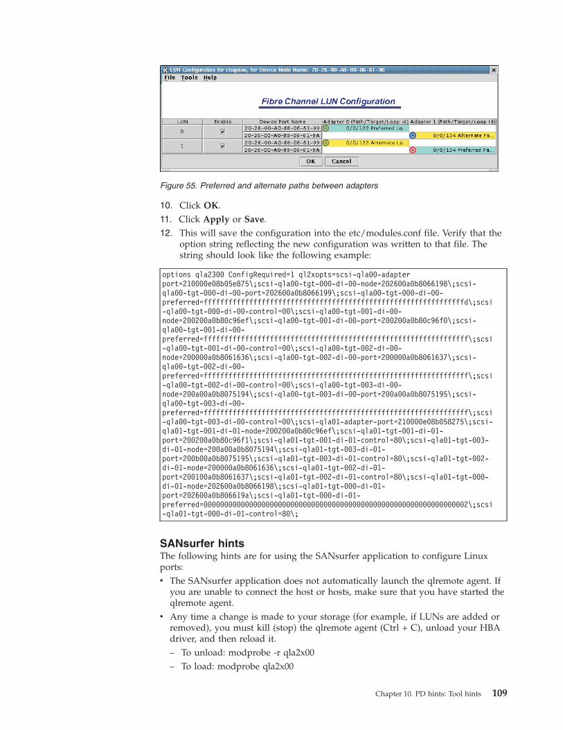
10. Click OK.
11. Click Apply or Save.
12. This will save the configuration into the etc/modules.conf file. Verify that the
option string reflecting the new configuration was written to that file. The
string should look like the following example:
options qla2300 ConfigRequired=1 ql2xopts=scsi-qla00-adapter
port=210000e08b05e875\;scsi-qla00-tgt-000-di-00-node=202600a0b8066198\;scsi-
qla00-tgt-000-di-00-port=202600a0b8066199\;scsi-qla00-tgt-000-di-00-
preferred=fffffffffffffffffffffffffffffffffffffffffffffffffffffffffffffffd\;scsi
-qla00-tgt-000-di-00-control=00\;scsi-qla00-tgt-001-di-00-
node=200200a0b80c96ef\;scsi-qla00-tgt-001-di-00-port=200200a0b80c96f0\;scsi-
qla00-tgt-001-di-00-
preferred=ffffffffffffffffffffffffffffffffffffffffffffffffffffffffffffffff\;scsi
-qla00-tgt-001-di-00-control=00\;scsi-qla00-tgt-002-di-00-
node=200000a0b8061636\;scsi-qla00-tgt-002-di-00-port=200000a0b8061637\;scsi-
qla00-tgt-002-di-00-
preferred=ffffffffffffffffffffffffffffffffffffffffffffffffffffffffffffffff\;scsi
-qla00-tgt-002-di-00-control=00\;scsi-qla00-tgt-003-di-00-
node=200a00a0b8075194\;scsi-qla00-tgt-003-di-00-port=200a00a0b8075195\;scsi-
qla00-tgt-003-di-00-
preferred=ffffffffffffffffffffffffffffffffffffffffffffffffffffffffffffffff\;scsi
-qla00-tgt-003-di-00-control=00\;scsi-qla01-adapter-port=210000e08b058275\;scsi-
qla01-tgt-001-di-01-node=200200a0b80c96ef\;scsi-qla01-tgt-001-di-01-
port=200200a0b80c96f1\;scsi-qla01-tgt-001-di-01-control=80\;scsi-qla01-tgt-003-
di-01-node=200a00a0b8075194\;scsi-qla01-tgt-003-di-01-
port=200b00a0b8075195\;scsi-qla01-tgt-003-di-01-control=80\;scsi-qla01-tgt-002-
di-01-node=200000a0b8061636\;scsi-qla01-tgt-002-di-01-
port=200100a0b8061637\;scsi-qla01-tgt-002-di-01-control=80\;scsi-qla01-tgt-000-
di-01-node=202600a0b8066198\;scsi-qla01-tgt-000-di-01-
port=202600a0b806619a\;scsi-qla01-tgt-000-di-01-
preferred=0000000000000000000000000000000000000000000000000000000000000002\;scsi
-qla01-tgt-000-di-01-control=80\;
SANsurfer hints
The following hints are for using the SANsurfer application to configure Linux
ports:
v The SANsurfer application does not automatically launch the qlremote agent. If
you are unable to connect the host or hosts, make sure that you have started the
qlremote agent.
v Any time a change is made to your storage (for example, if LUNs are added or
removed), you must kill (stop) the qlremote agent (Ctrl + C), unload your HBA
driver, and then reload it.
– To unload: modprobe -r qla2x00
– To load: modprobe qla2x00
Figure 55. Preferred and alternate paths between adapters
Chapter 10. PD hints: Tool hints 109

– To restart: qlremoteYou will then need to run the SANsurfer application to perform failover
configuration.
v Do not mix HBA types. For example, qla2200 must be matched with another
qla2200.
v If you replace an HBA, make sure that you change the mapping in the DS4000
Storage Manager to point to the WWN name for the new adapter. You will then
need to reconfigure your storage.
110 IBM System Storage DS4000: Problem Determination Guide
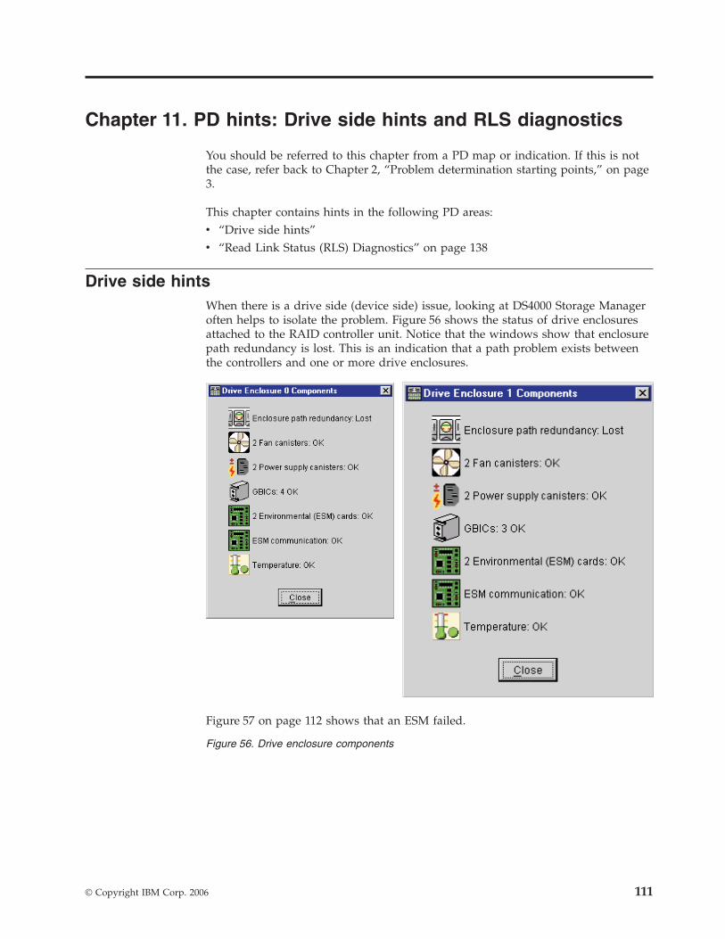
Chapter 11. PD hints: Drive side hints and RLS diagnostics
You should be referred to this chapter from a PD map or indication. If this is not
the case, refer back to Chapter 2, “Problem determination starting points,” on page
3.
This chapter contains hints in the following PD areas:
v “Drive side hints”
v “Read Link Status (RLS) Diagnostics” on page 138
Drive side hints
When there is a drive side (device side) issue, looking at DS4000 Storage Manager
often helps to isolate the problem. Figure 56 shows the status of drive enclosures
attached to the RAID controller unit. Notice that the windows show that enclosure
path redundancy is lost. This is an indication that a path problem exists between
the controllers and one or more drive enclosures.
Figure 57 on page 112 shows that an ESM failed.
Figure 56. Drive enclosure components
© Copyright IBM Corp. 2006 111
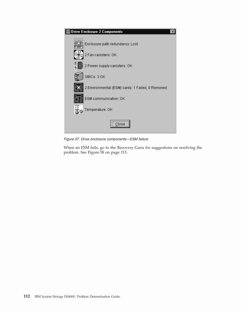
When an ESM fails, go to the Recovery Guru for suggestions on resolving the
problem. See Figure 58 on page 113.
Figure 57. Drive enclosure components—ESM failure
112 IBM System Storage DS4000: Problem Determination Guide

Note: In the Recovery Guru window, the message Logical drive not on
preferred path does not necessarily pertain to the current problem. The
drive could have been moved to the other controller and not moved back.
The loss of redundancy and the failed ESM are what is important.
Figure 59 on page 114 also shows the message Failed or Removed Power Supply
Cannister. However, this message is not significant here because the power supply
was removed for purposes of illustration.
Figure 58. Recovery Guru window
Chapter 11. PD hints: Drive side hints and RLS diagnostics 113
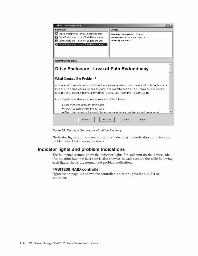
“Indicator lights and problem indications” identifies the indicators for drive side
problems for DS400 series products.
Indicator lights and problem indications
The following sections show the indicator lights for each unit on the device side
(for the mini-hub, the host side is also shown). In each section, the table following
each figure shows the normal and problem indications.
FAStT200 RAID controller
Figure 60 on page 115 shows the controller indicator lights for a FAStT200
controller.
Figure 59. Recovery Guru—Loss of path redundancy
114 IBM System Storage DS4000: Problem Determination Guide
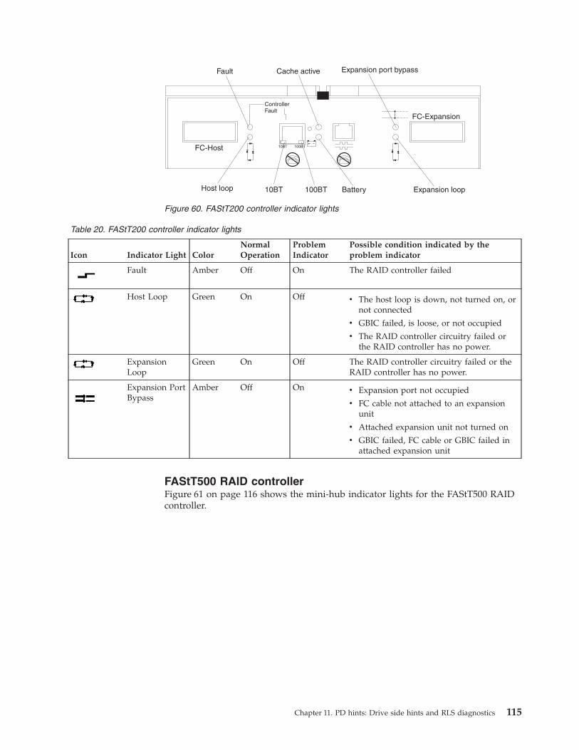
Table 20. FAStT200 controller indicator lights
Icon Indicator Light Color
Normal
Operation
Problem
Indicator
Possible condition indicated by the
problem indicator
Fault Amber Off On The RAID controller failed
Host Loop Green On Off v The host loop is down, not turned on, or
not connected
v GBIC failed, is loose, or not occupied
v The RAID controller circuitry failed or
the RAID controller has no power.
Expansion
Loop
Green On Off The RAID controller circuitry failed or the
RAID controller has no power.
Expansion Port
Bypass
Amber Off On v Expansion port not occupied
v FC cable not attached to an expansion
unit
v Attached expansion unit not turned on
v GBIC failed, FC cable or GBIC failed in
attached expansion unit
FAStT500 RAID controller
Figure 61 on page 116 shows the mini-hub indicator lights for the FAStT500 RAID
controller.
Fault
Host loop 10BT 100BT Battery Expansion loop
Expansion port bypassCache active
ControllerFault
10BT 100BTFC-Host
FC-Expansion
Figure 60. FAStT200 controller indicator lights
Chapter 11. PD hints: Drive side hints and RLS diagnostics 115
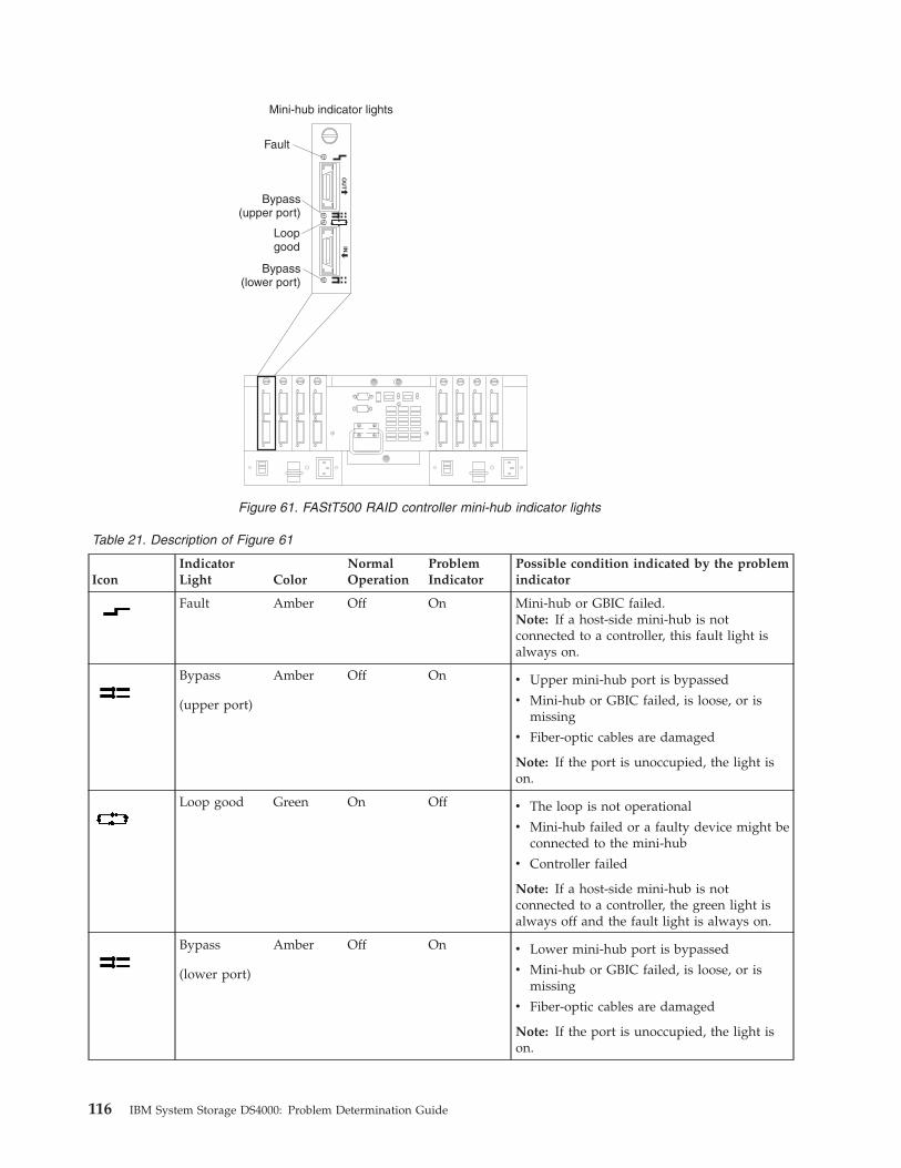
Table 21. Description of Figure 61
Icon
Indicator
Light Color
Normal
Operation
Problem
Indicator
Possible condition indicated by the problem
indicator
Fault Amber Off On Mini-hub or GBIC failed.
Note: If a host-side mini-hub is not
connected to a controller, this fault light is
always on.
Bypass
(upper port)
Amber Off On v Upper mini-hub port is bypassed
v Mini-hub or GBIC failed, is loose, or is
missing
v Fiber-optic cables are damaged
Note: If the port is unoccupied, the light is
on.
Loop good Green On Off v The loop is not operational
v Mini-hub failed or a faulty device might be
connected to the mini-hub
v Controller failed
Note: If a host-side mini-hub is not
connected to a controller, the green light is
always off and the fault light is always on.
Bypass
(lower port)
Amber Off On v Lower mini-hub port is bypassed
v Mini-hub or GBIC failed, is loose, or is
missing
v Fiber-optic cables are damaged
Note: If the port is unoccupied, the light is
on.
OU
TIN
Fault
Bypass(upper port)
Bypass(lower port)
Loopgood
Mini-hub indicator lights
Figure 61. FAStT500 RAID controller mini-hub indicator lights
116 IBM System Storage DS4000: Problem Determination Guide

DS4300 and DS4100 RAID controllers
Figure 62 shows the RAID controller indicator lights for the DS4300 and DS4100
Storage Servers.
Table 22. Description of Figure 62
Icon LED Color Operating states1
Fault Amber v Off - Normal operation.
v On - One of the following situations has
occurred:
– The RAID controller has failed.
– The RAID controller was placed offline
– The controller battery had failed (in
conjunction with the battery LED in off
state).
Host loop Green v On - Normal operation.
v Off - One of the following situations has
occurred:
– The host loop is down, not turned on,
or not connected.
– A SFP has failed, or the host port is not
occupied.
– The RAID controller circuitry has failed,
or the RAID controller has no power.
Cache active Green v On - There is data in the RAID controller
cache.
v Off - One of the following situations has
occurred:
– There is no data in cache.
– There are no cache options selected for
this array.
– The cache memory has failed, or the
battery has failed.
+
Battery Green v On - Normal operation.
v Flashing - The battery is recharging or
performing a self-test.
v Off - The battery or battery charger has
failed.
Controllerfault
Expansionby-pass
Expansion
10BT
2Gb/s2Gb/s
10101
100BT Batterycharging
Expansion link indicator
Cacheactive
10BT 100BT
Host 1
Host 1indicator
Host 2indicator
Host 2
+
2Gbps
f10ug025
Figure 62. DS4300 and DS4100 RAID controller LEDs
Chapter 11. PD hints: Drive side hints and RLS diagnostics 117
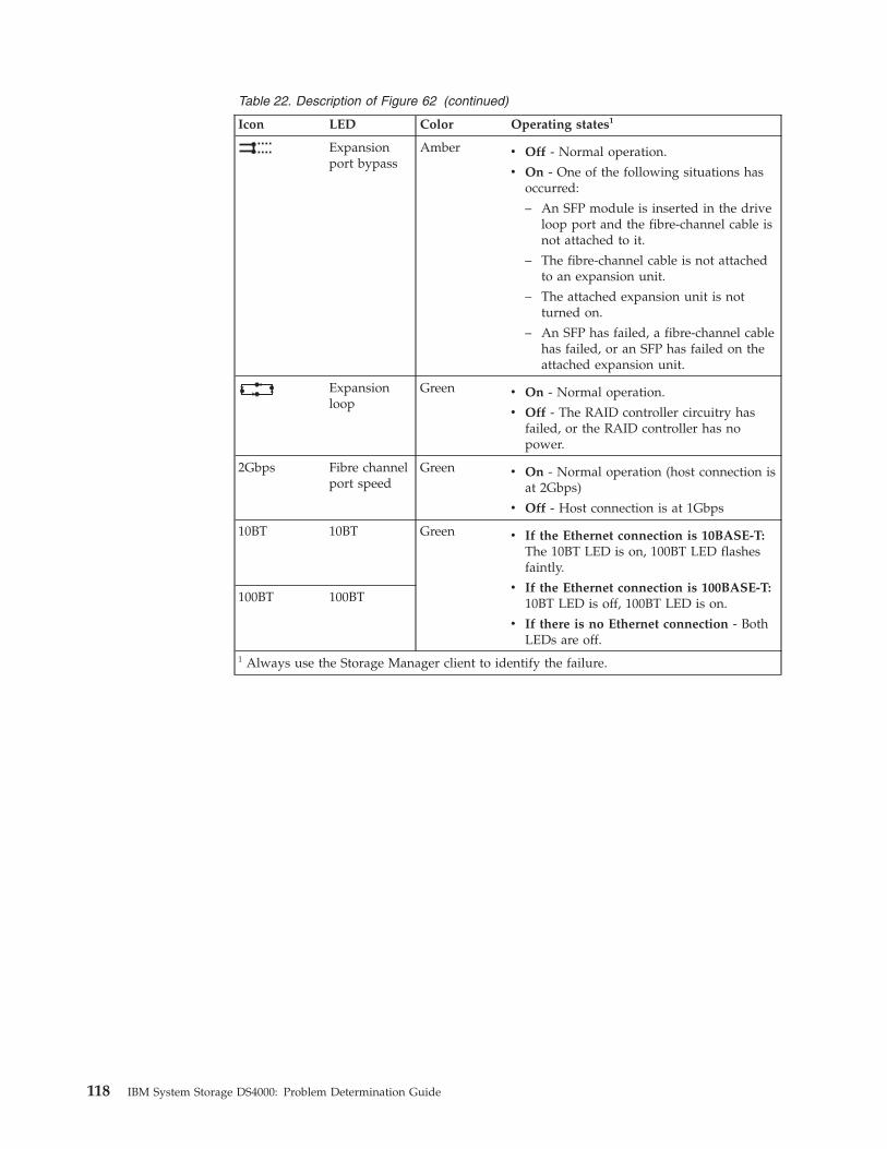
Table 22. Description of Figure 62 (continued)
Icon LED Color Operating states1
Expansion
port bypass
Amber v Off - Normal operation.
v On - One of the following situations has
occurred:
– An SFP module is inserted in the drive
loop port and the fibre-channel cable is
not attached to it.
– The fibre-channel cable is not attached
to an expansion unit.
– The attached expansion unit is not
turned on.
– An SFP has failed, a fibre-channel cable
has failed, or an SFP has failed on the
attached expansion unit.
Expansion
loop
Green v On - Normal operation.
v Off - The RAID controller circuitry has
failed, or the RAID controller has no
power.
2Gbps Fibre channel
port speed
Green v On - Normal operation (host connection is
at 2Gbps)
v Off - Host connection is at 1Gbps
10BT 10BT Green v If the Ethernet connection is 10BASE-T:
The 10BT LED is on, 100BT LED flashes
faintly.
v If the Ethernet connection is 100BASE-T:
10BT LED is off, 100BT LED is on.
v If there is no Ethernet connection - Both
LEDs are off.
100BT 100BT
1 Always use the Storage Manager client to identify the failure.
118 IBM System Storage DS4000: Problem Determination Guide
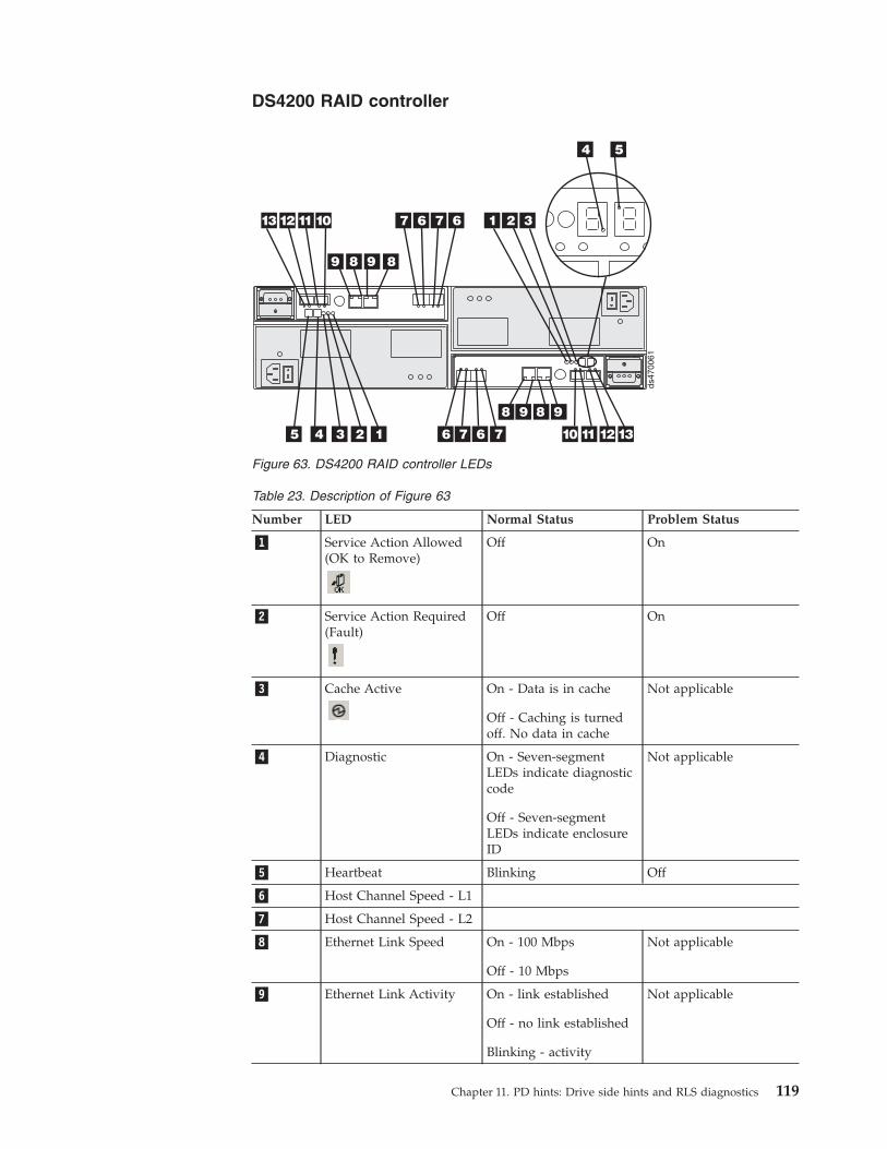
DS4200 RAID controller
Table 23. Description of Figure 63
Number LED Normal Status Problem Status
�1� Service Action Allowed
(OK to Remove)
Off On
�2� Service Action Required
(Fault)
Off On
�3� Cache Active
On - Data is in cache
Off - Caching is turned
off. No data in cache
Not applicable
�4� Diagnostic On - Seven-segment
LEDs indicate diagnostic
code
Off - Seven-segment
LEDs indicate enclosure
ID
Not applicable
�5� Heartbeat Blinking Off
�6� Host Channel Speed - L1
�7� Host Channel Speed - L2
�8� Ethernet Link Speed On - 100 Mbps
Off - 10 Mbps
Not applicable
�9� Ethernet Link Activity On - link established
Off - no link established
Blinking - activity
Not applicable
ds47
0061
2 3
4 5
67
898
16 7
9
10111213
2345 6 7
8 9 8
1 67
9
10 11 12 13
Figure 63. DS4200 RAID controller LEDs
Chapter 11. PD hints: Drive side hints and RLS diagnostics 119
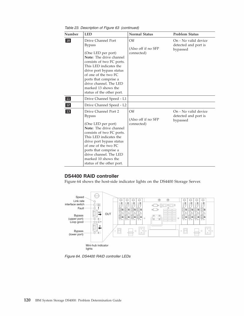
Table 23. Description of Figure 63 (continued)
Number LED Normal Status Problem Status
�10� Drive Channel Port
Bypass
(One LED per port)
Note: The drive channel
consists of two FC ports.
This LED indicates the
drive port bypass status
of one of the two FC
ports that comprise a
drive channel. The LED
marked 13 shows the
status of the other port.
Off
(Also off if no SFP
connected)
On - No valid device
detected and port is
bypassed
�11� Drive Channel Speed - L1
�12� Drive Channel Speed - L2
�13� Drive Channel Port 2
Bypass
(One LED per port)
Note: The drive channel
consists of two FC ports.
This LED indicates the
drive port bypass status
of one of the two FC
ports that comprise a
drive channel. The LED
marked 10 shows the
status of the other port.
Off
(Also off if no SFP
connected)
On - No valid device
detected and port is
bypassed
DS4400 RAID controller
Figure 64 shows the host-side indicator lights on the DS4400 Storage Server.
OUT
IN
!2 Gb/s1 Gb/s
OUT
IN
!2 Gb/s1 Gb/s
OUT
IN
!2 Gb/s1 Gb/s
OUT
IN
!2 Gb/s1 Gb/s
OUT
IN
!2 Gb/s1 Gb/s
OUT
IN
!2 Gb/s1 Gb/s
OUT
IN
!2 Gb/s1 Gb/s
OUT
IN
!2 Gb/s1 Gb/s
OUT
IN
!2 Gb/s1 Gb/s
OUT
Speed
Bypass(upper port)
Bypass(lower port)
Loop good
Fault
Mini-hub indicatorlights
Link rateinterface switch
Figure 64. DS4400 RAID controller LEDs
120 IBM System Storage DS4000: Problem Determination Guide
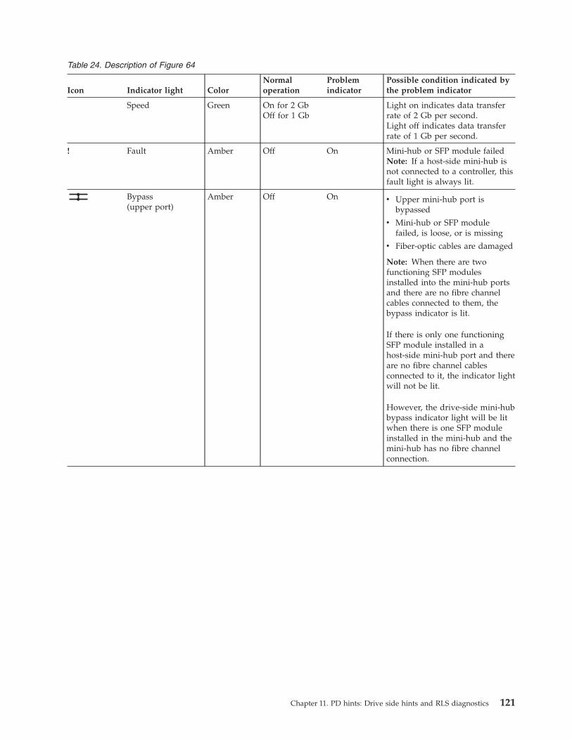
Table 24. Description of Figure 64
Icon Indicator light Color
Normal
operation
Problem
indicator
Possible condition indicated by
the problem indicator
Speed Green On for 2 Gb
Off for 1 Gb
Light on indicates data transfer
rate of 2 Gb per second.
Light off indicates data transfer
rate of 1 Gb per second.
! Fault Amber Off On Mini-hub or SFP module failed
Note: If a host-side mini-hub is
not connected to a controller, this
fault light is always lit.
Bypass
(upper port)
Amber Off On v Upper mini-hub port is
bypassed
v Mini-hub or SFP module
failed, is loose, or is missing
v Fiber-optic cables are damaged
Note: When there are two
functioning SFP modules
installed into the mini-hub ports
and there are no fibre channel
cables connected to them, the
bypass indicator is lit.
If there is only one functioning
SFP module installed in a
host-side mini-hub port and there
are no fibre channel cables
connected to it, the indicator light
will not be lit.
However, the drive-side mini-hub
bypass indicator light will be lit
when there is one SFP module
installed in the mini-hub and the
mini-hub has no fibre channel
connection.
Chapter 11. PD hints: Drive side hints and RLS diagnostics 121
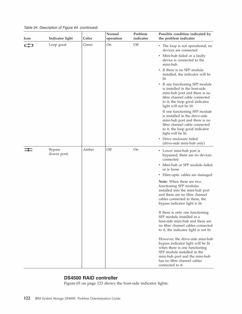
Table 24. Description of Figure 64 (continued)
Icon Indicator light Color
Normal
operation
Problem
indicator
Possible condition indicated by
the problem indicator
Loop good Green On Off v The loop is not operational, no
devices are connected
v Mini-hub failed or a faulty
device is connected to the
mini-hub
v If there is no SFP module
installed, the indicator will be
lit
v If one functioning SFP module
is installed in the host-side
mini-hub port and there is no
fibre channel cable connected
to it, the loop good indicator
light will not be lit.
If one functioning SFP module
is installed in the drive-side
mini-hub port and there is no
fibre channel cable connected
to it, the loop good indicator
light will be lit.
v Drive enclosure failed
(drive-side mini-hub only)
Bypass
(lower port)
Amber Off On v Lower mini-hub port is
bypassed; there are no devices
connected
v Mini-hub or SFP module failed
or is loose
v Fiber-optic cables are damaged
Note: When there are two
functioning SFP modules
installed into the mini-hub port
and there are no fibre channel
cables connected to them, the
bypass indicator light is lit.
If there is only one functioning
SFP module installed in a
host-side mini-hub and there are
no fibre channel cables connected
to it, the indicator light is not lit.
However, the drive-side mini-hub
bypass indicator light will be lit
when there is one functioning
SFP module installed in the
mini-hub port and the mini-hub
has no fibre channel cables
connected to it.
DS4500 RAID controller
Figure 65 on page 123 shows the host-side indicator lights.
122 IBM System Storage DS4000: Problem Determination Guide
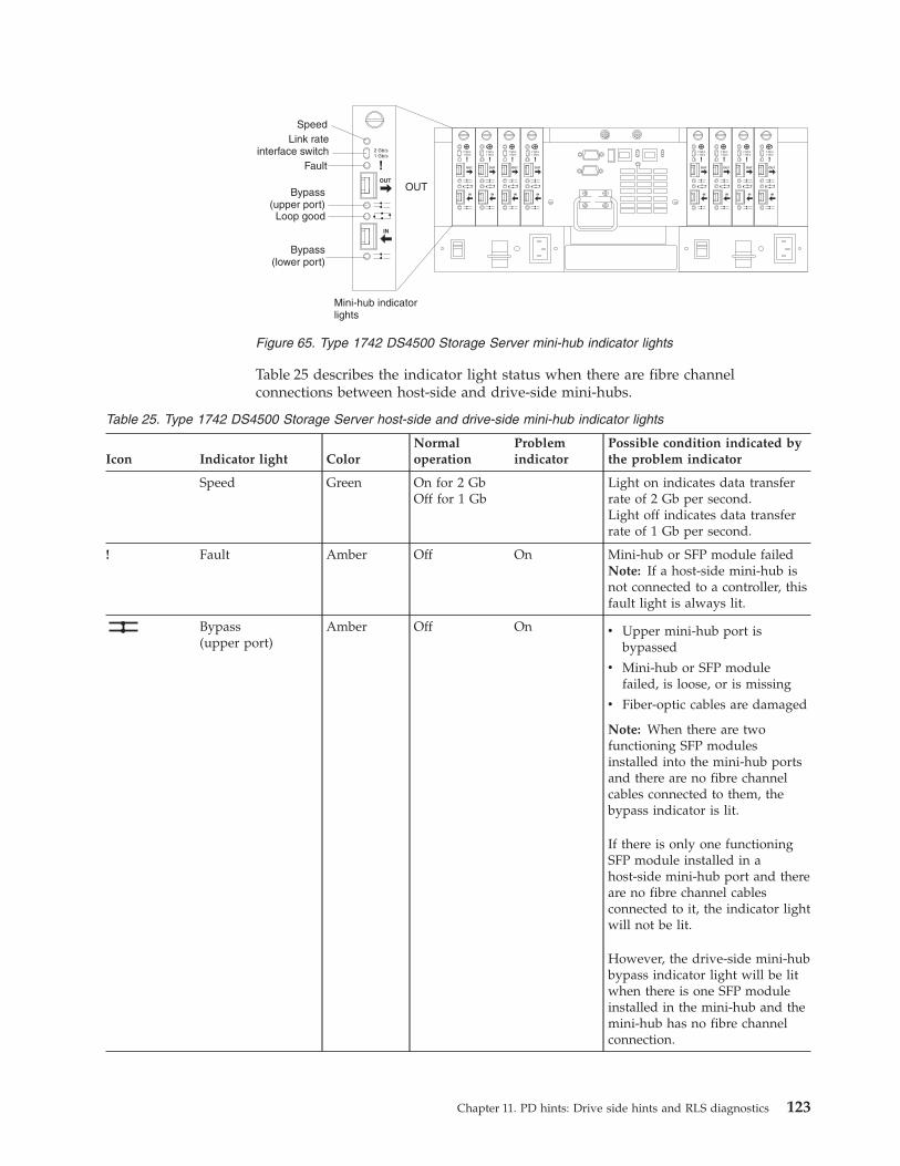
Table 25 describes the indicator light status when there are fibre channel
connections between host-side and drive-side mini-hubs.
Table 25. Type 1742 DS4500 Storage Server host-side and drive-side mini-hub indicator lights
Icon Indicator light Color
Normal
operation
Problem
indicator
Possible condition indicated by
the problem indicator
Speed Green On for 2 Gb
Off for 1 Gb
Light on indicates data transfer
rate of 2 Gb per second.
Light off indicates data transfer
rate of 1 Gb per second.
! Fault Amber Off On Mini-hub or SFP module failed
Note: If a host-side mini-hub is
not connected to a controller, this
fault light is always lit.
Bypass
(upper port)
Amber Off On v Upper mini-hub port is
bypassed
v Mini-hub or SFP module
failed, is loose, or is missing
v Fiber-optic cables are damaged
Note: When there are two
functioning SFP modules
installed into the mini-hub ports
and there are no fibre channel
cables connected to them, the
bypass indicator is lit.
If there is only one functioning
SFP module installed in a
host-side mini-hub port and there
are no fibre channel cables
connected to it, the indicator light
will not be lit.
However, the drive-side mini-hub
bypass indicator light will be lit
when there is one SFP module
installed in the mini-hub and the
mini-hub has no fibre channel
connection.
OUT
IN
!2 Gb/s1 Gb/s
OUT
IN
!2 Gb/s1 Gb/s
OUT
IN
!2 Gb/s1 Gb/s
OUT
IN
!2 Gb/s1 Gb/s
OUT
IN
!2 Gb/s1 Gb/s
OUT
IN
!2 Gb/s1 Gb/s
OUT
IN
!2 Gb/s1 Gb/s
OUT
IN
!2 Gb/s1 Gb/s
OUT
IN
!2 Gb/s1 Gb/s
OUT
Speed
Bypass(upper port)
Bypass(lower port)
Loop good
Fault
Mini-hub indicatorlights
Link rateinterface switch
Figure 65. Type 1742 DS4500 Storage Server mini-hub indicator lights
Chapter 11. PD hints: Drive side hints and RLS diagnostics 123
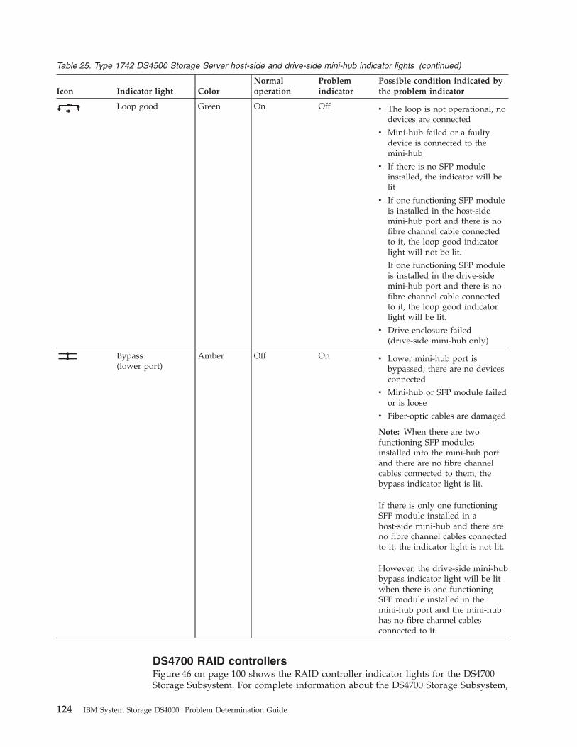
Table 25. Type 1742 DS4500 Storage Server host-side and drive-side mini-hub indicator lights (continued)
Icon Indicator light Color
Normal
operation
Problem
indicator
Possible condition indicated by
the problem indicator
Loop good Green On Off v The loop is not operational, no
devices are connected
v Mini-hub failed or a faulty
device is connected to the
mini-hub
v If there is no SFP module
installed, the indicator will be
lit
v If one functioning SFP module
is installed in the host-side
mini-hub port and there is no
fibre channel cable connected
to it, the loop good indicator
light will not be lit.
If one functioning SFP module
is installed in the drive-side
mini-hub port and there is no
fibre channel cable connected
to it, the loop good indicator
light will be lit.
v Drive enclosure failed
(drive-side mini-hub only)
Bypass
(lower port)
Amber Off On v Lower mini-hub port is
bypassed; there are no devices
connected
v Mini-hub or SFP module failed
or is loose
v Fiber-optic cables are damaged
Note: When there are two
functioning SFP modules
installed into the mini-hub port
and there are no fibre channel
cables connected to them, the
bypass indicator light is lit.
If there is only one functioning
SFP module installed in a
host-side mini-hub and there are
no fibre channel cables connected
to it, the indicator light is not lit.
However, the drive-side mini-hub
bypass indicator light will be lit
when there is one functioning
SFP module installed in the
mini-hub port and the mini-hub
has no fibre channel cables
connected to it.
DS4700 RAID controllers
Figure 46 on page 100 shows the RAID controller indicator lights for the DS4700
Storage Subsystem. For complete information about the DS4700 Storage Subsystem,
124 IBM System Storage DS4000: Problem Determination Guide
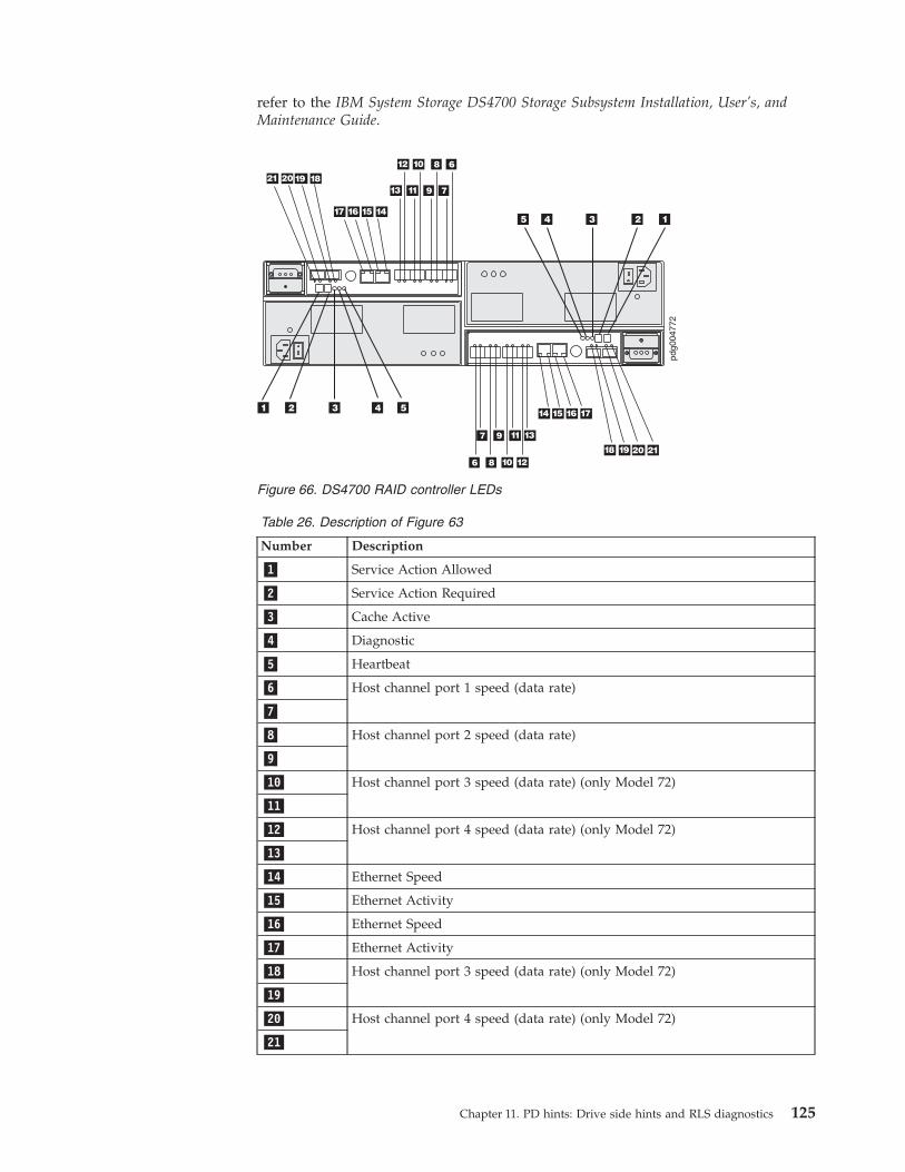
refer to the IBM System Storage DS4700 Storage Subsystem Installation, User’s, and
Maintenance Guide.
Table 26. Description of Figure 63
Number Description
�1� Service Action Allowed
�2� Service Action Required
�3� Cache Active
�4� Diagnostic
�5� Heartbeat
�6� Host channel port 1 speed (data rate)
�7�
�8� Host channel port 2 speed (data rate)
�9�
�10� Host channel port 3 speed (data rate) (only Model 72)
�11�
�12� Host channel port 4 speed (data rate) (only Model 72)
�13�
�14� Ethernet Speed
�15� Ethernet Activity
�16� Ethernet Speed
�17� Ethernet Activity
�18� Host channel port 3 speed (data rate) (only Model 72)
�19�
�20� Host channel port 4 speed (data rate) (only Model 72)
�21�
Figure 66. DS4700 RAID controller LEDs
Chapter 11. PD hints: Drive side hints and RLS diagnostics 125
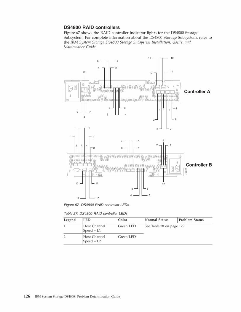
DS4800 RAID controllers
Figure 67 shows the RAID controller indicator lights for the DS4800 Storage
Subsystem. For complete information about the DS4800 Storage Subsystem, refer to
the IBM System Storage DS4800 Storage Subsystem Installation, User’s, and
Maintenance Guide.
Table 27. DS4800 RAID controller LEDs
Legend LED Color Normal Status Problem Status
1 Host Channel
Speed – L1
Green LED See Table 28 on page 129.
2 Host Channel
Speed – L2
Green LED
Controller A
Controller B
ds48041
12
12
7
8
9
9
8
7
3
4 5
6
3
4 5
6
3
45
6
3
45
6
10
10
11
11
10
10
11
11
1
1 1
1
2 2 22
2
2 2
2
1 1 11
Figure 67. DS4800 RAID controller LEDs
126 IBM System Storage DS4000: Problem Determination Guide

Table 27. DS4800 RAID controller LEDs (continued)
Legend LED Color Normal Status Problem Status
3 Drive Port Bypass
(one LED per port)
Amber LED Off On = Bypass
problem
v An SFP module is
inserted in the
port and the
connected fibre
channel is either
absent or not
properly
connected
v The storage
expansion
enclosure
connected to this
port is not
powered on
v There is a
problem with the
fibre channel
connection
between this port
and the fibre
channel port of
the connected
ESM in the
storage expansion
enclosure.
4 Drive Channel
Speed – L1
Green LED See Table 28 on page 129.
5 Drive Channel
Speed – L2
Green LED
Chapter 11. PD hints: Drive side hints and RLS diagnostics 127
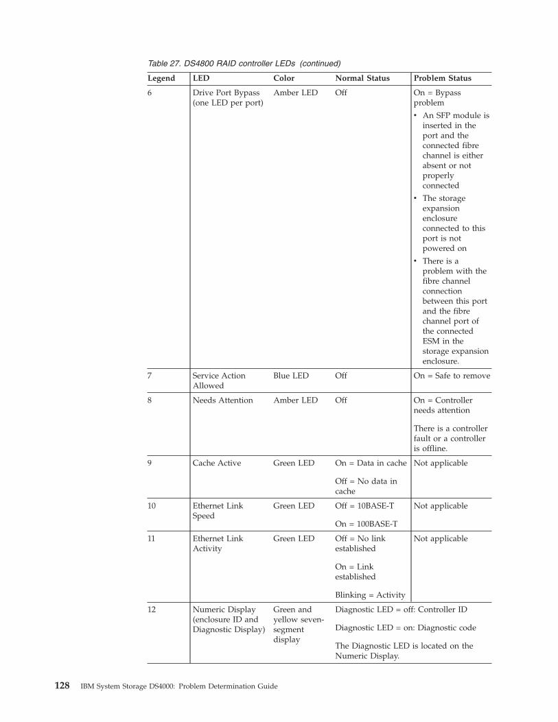
Table 27. DS4800 RAID controller LEDs (continued)
Legend LED Color Normal Status Problem Status
6 Drive Port Bypass
(one LED per port)
Amber LED Off On = Bypass
problem
v An SFP module is
inserted in the
port and the
connected fibre
channel is either
absent or not
properly
connected
v The storage
expansion
enclosure
connected to this
port is not
powered on
v There is a
problem with the
fibre channel
connection
between this port
and the fibre
channel port of
the connected
ESM in the
storage expansion
enclosure.
7 Service Action
Allowed
Blue LED Off On = Safe to remove
8 Needs Attention Amber LED Off On = Controller
needs attention
There is a controller
fault or a controller
is offline.
9 Cache Active Green LED On = Data in cache
Off = No data in
cache
Not applicable
10 Ethernet Link
Speed
Green LED Off = 10BASE-T
On = 100BASE-T
Not applicable
11 Ethernet Link
Activity
Green LED Off = No link
established
On = Link
established
Blinking = Activity
Not applicable
12 Numeric Display
(enclosure ID and
Diagnostic Display)
Green and
yellow seven-
segment
display
Diagnostic LED = off: Controller ID
Diagnostic LED = on: Diagnostic code
The Diagnostic LED is located on the
Numeric Display.
128 IBM System Storage DS4000: Problem Determination Guide
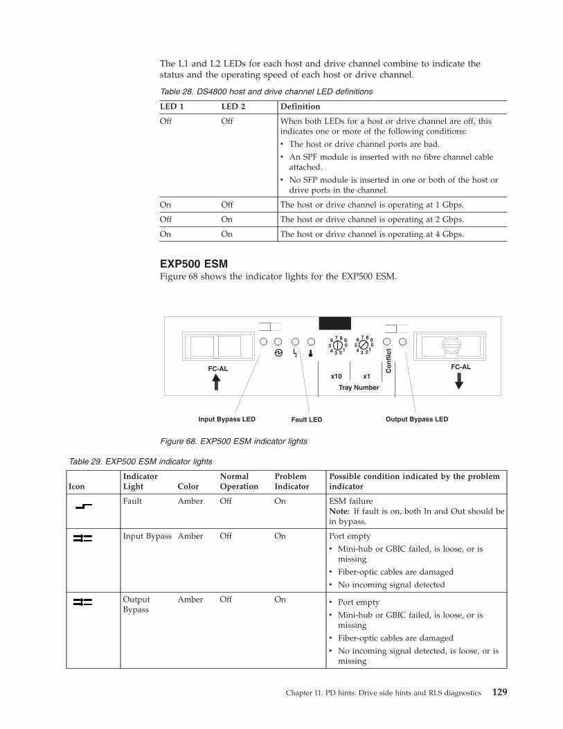
The L1 and L2 LEDs for each host and drive channel combine to indicate the
status and the operating speed of each host or drive channel.
Table 28. DS4800 host and drive channel LED definitions
LED 1 LED 2 Definition
Off Off When both LEDs for a host or drive channel are off, this
indicates one or more of the following conditions:
v The host or drive channel ports are bad.
v An SPF module is inserted with no fibre channel cable
attached.
v No SFP module is inserted in one or both of the host or
drive ports in the channel.
On Off The host or drive channel is operating at 1 Gbps.
Off On The host or drive channel is operating at 2 Gbps.
On On The host or drive channel is operating at 4 Gbps.
EXP500 ESM
Figure 68 shows the indicator lights for the EXP500 ESM.
Table 29. EXP500 ESM indicator lights
Icon
Indicator
Light Color
Normal
Operation
Problem
Indicator
Possible condition indicated by the problem
indicator
Fault Amber Off On ESM failure
Note: If fault is on, both In and Out should be
in bypass.
Input Bypass Amber Off On Port empty
v Mini-hub or GBIC failed, is loose, or is
missing
v Fiber-optic cables are damaged
v No incoming signal detected
Output
Bypass
Amber Off On v Port empty
v Mini-hub or GBIC failed, is loose, or is
missing
v Fiber-optic cables are damaged
v No incoming signal detected, is loose, or is
missing
Output Bypass LEDFault LEDInput Bypass LED
FC-AL FC-AL
Tray Number
x10 x1
Co
nfl
ict1 1
2 23 34 45 56 67 7
9 90 0
8 8
Figure 68. EXP500 ESM indicator lights
Chapter 11. PD hints: Drive side hints and RLS diagnostics 129
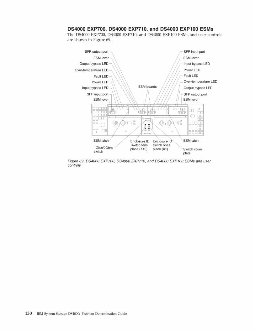
DS4000 EXP700, DS4000 EXP710, and DS4000 EXP100 ESMs
The DS4000 EXP700, DS4000 EXP710, and DS4000 EXP100 ESMs and user controls
are shown in Figure 69.
1 Gb/s 2 Gb/s
X10 X1
Tray Number
Conflict
ESM boards
Enclosure IDswitch tensplace (X10)
Enclosure IDswitch onesplace (X1)
SFP output port
SFP output port
Output bypass LED
Output bypass LED
Over-temperature LED
Over-temperature LED
Fault LED Fault LED
Power LED
Power LED
Input bypass LED
Input bypass LED
SFP input port
SFP input port
ESM lever
ESM lever
ESM latch
ESM lever
ESM lever
ESM latch
Switch coverplate
1Gb/s/2Gb/sswitch
Figure 69. DS4000 EXP700, DS4000 EXP710, and DS4000 EXP100 ESMs and user
controls
130 IBM System Storage DS4000: Problem Determination Guide
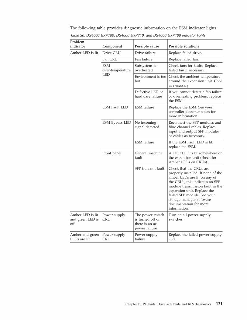
The following table provides diagnostic information on the ESM indicator lights.
Table 30. DS4000 EXP700, DS4000 EXP710, and DS4000 EXP100 indicator lights
Problem
indicator Component Possible cause Possible solutions
Amber LED is lit Drive CRU Drive failure Replace failed drive.
Fan CRU Fan failure Replace failed fan.
ESM
over-temperature
LED
Subsystem is
overheated
Check fans for faults. Replace
failed fan if necessary.
Environment is too
hot
Check the ambient temperature
around the expansion unit. Cool
as necessary.
Defective LED or
hardware failure
If you cannot detect a fan failure
or overheating problem, replace
the ESM.
ESM Fault LED ESM failure Replace the ESM. See your
controller documentation for
more information.
ESM Bypass LED No incoming
signal detected
Reconnect the SFP modules and
fibre channel cables. Replace
input and output SFP modules
or cables as necessary.
ESM failure If the ESM Fault LED is lit,
replace the ESM.
Front panel General machine
fault
A Fault LED is lit somewhere on
the expansion unit (check for
Amber LEDs on CRUs).
SFP transmit fault Check that the CRUs are
properly installed. If none of the
amber LEDs are lit on any of
the CRUs, this indicates an SFP
module transmission fault in the
expansion unit. Replace the
failed SFP module. See your
storage-manager software
documentation for more
information.
Amber LED is lit
and green LED is
off
Power-supply
CRU
The power switch
is turned off or
there is an ac
power failure
Turn on all power-supply
switches.
Amber and green
LEDs are lit
Power-supply
CRU
Power-supply
failure
Replace the failed power-supply
CRU.
Chapter 11. PD hints: Drive side hints and RLS diagnostics 131
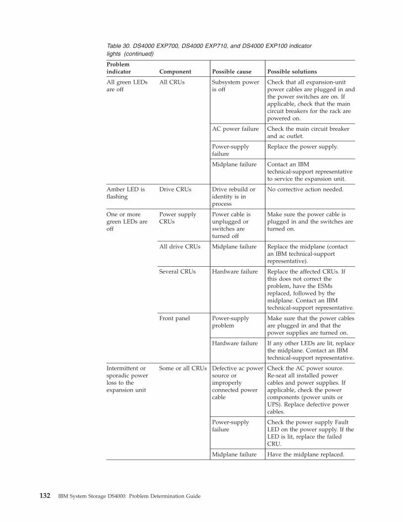
Table 30. DS4000 EXP700, DS4000 EXP710, and DS4000 EXP100 indicator
lights (continued)
Problem
indicator Component Possible cause Possible solutions
All green LEDs
are off
All CRUs Subsystem power
is off
Check that all expansion-unit
power cables are plugged in and
the power switches are on. If
applicable, check that the main
circuit breakers for the rack are
powered on.
AC power failure Check the main circuit breaker
and ac outlet.
Power-supply
failure
Replace the power supply.
Midplane failure Contact an IBM
technical-support representative
to service the expansion unit.
Amber LED is
flashing
Drive CRUs Drive rebuild or
identity is in
process
No corrective action needed.
One or more
green LEDs are
off
Power supply
CRUs
Power cable is
unplugged or
switches are
turned off
Make sure the power cable is
plugged in and the switches are
turned on.
All drive CRUs Midplane failure Replace the midplane (contact
an IBM technical-support
representative).
Several CRUs Hardware failure Replace the affected CRUs. If
this does not correct the
problem, have the ESMs
replaced, followed by the
midplane. Contact an IBM
technical-support representative.
Front panel Power-supply
problem
Make sure that the power cables
are plugged in and that the
power supplies are turned on.
Hardware failure If any other LEDs are lit, replace
the midplane. Contact an IBM
technical-support representative.
Intermittent or
sporadic power
loss to the
expansion unit
Some or all CRUs Defective ac power
source or
improperly
connected power
cable
Check the AC power source.
Re-seat all installed power
cables and power supplies. If
applicable, check the power
components (power units or
UPS). Replace defective power
cables.
Power-supply
failure
Check the power supply Fault
LED on the power supply. If the
LED is lit, replace the failed
CRU.
Midplane failure Have the midplane replaced.
132 IBM System Storage DS4000: Problem Determination Guide
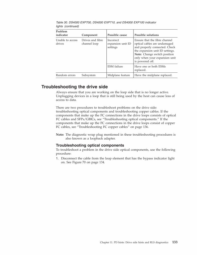
Table 30. DS4000 EXP700, DS4000 EXP710, and DS4000 EXP100 indicator
lights (continued)
Problem
indicator Component Possible cause Possible solutions
Unable to access
drives
Drives and fibre
channel loop
Incorrect
expansion unit ID
settings
Ensure that the fibre channel
optical cables are undamaged
and properly connected. Check
the expansion unit ID settings.
Note: Change switch position
only when your expansion unit
is powered off.
ESM failure Have one or both ESMs
replaced.
Random errors Subsystem Midplane feature Have the midplane replaced.
Troubleshooting the drive side
Always ensure that you are working on the loop side that is no longer active.
Unplugging devices in a loop that is still being used by the host can cause loss of
access to data.
There are two procedures to troubleshoot problems on the drive side:
troubleshooting optical components and troubleshooting copper cables. If the
components that make up the FC connections in the drive loops consists of optical
FC cables and SFPs/GBICs, see “Troubleshooting optical components.” If the
components that make up the FC connections in the drive loops consist of copper
FC cables, see “Troubleshooting FC copper cables” on page 136.
Note: The diagnostic wrap plug mentioned in these troubleshooting procedures is
also known as a loopback adapter.
Troubleshooting optical components
To troubleshoot a problem in the drive side optical components, use the following
procedure:
1. Disconnect the cable from the loop element that has the bypass indicator light
on. See Figure 70 on page 134.
Chapter 11. PD hints: Drive side hints and RLS diagnostics 133
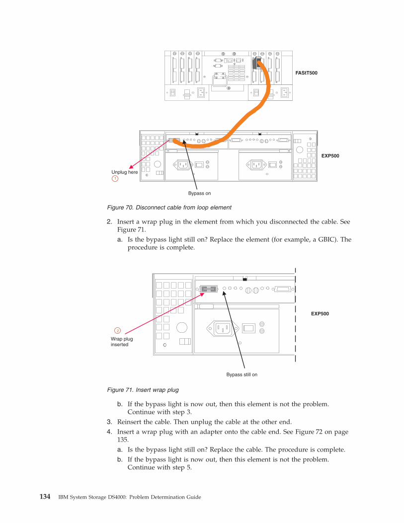
2. Insert a wrap plug in the element from which you disconnected the cable. See
Figure 71.
a. Is the bypass light still on? Replace the element (for example, a GBIC). The
procedure is complete.
b. If the bypass light is now out, then this element is not the problem.
Continue with step 3.3. Reinsert the cable. Then unplug the cable at the other end.
4. Insert a wrap plug with an adapter onto the cable end. See Figure 72 on page
135.
a. Is the bypass light still on? Replace the cable. The procedure is complete.
b. If the bypass light is now out, then this element is not the problem.
Continue with step 5.
Unplug here
Bypass on
FAStT500
EXP500
1
Figure 70. Disconnect cable from loop element
EXP500
Wrap pluginserted
Bypass still on
2
Figure 71. Insert wrap plug
134 IBM System Storage DS4000: Problem Determination Guide
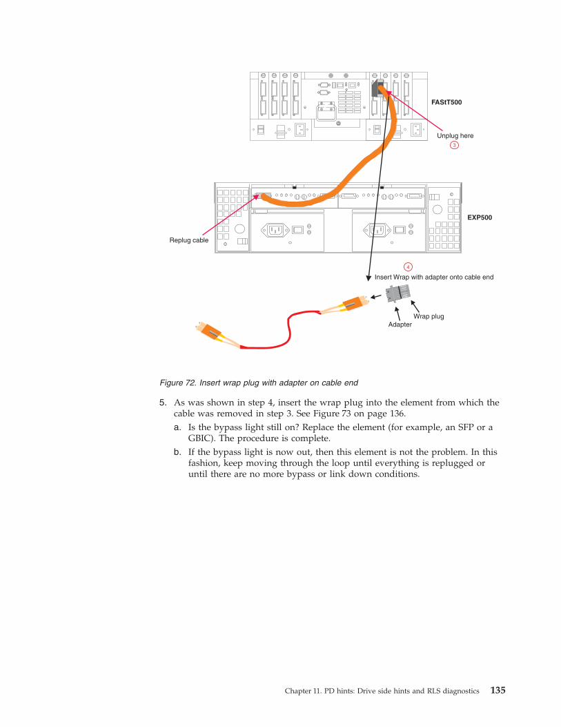
5. As was shown in step 4, insert the wrap plug into the element from which the
cable was removed in step 3. See Figure 73 on page 136.
a. Is the bypass light still on? Replace the element (for example, an SFP or a
GBIC). The procedure is complete.
b. If the bypass light is now out, then this element is not the problem. In this
fashion, keep moving through the loop until everything is replugged or
until there are no more bypass or link down conditions.
Replug cable
Unplug here
Insert Wrap with adapter onto cable end
AdapterWrap plug
FAStT500
EXP500
3
4
Figure 72. Insert wrap plug with adapter on cable end
Chapter 11. PD hints: Drive side hints and RLS diagnostics 135
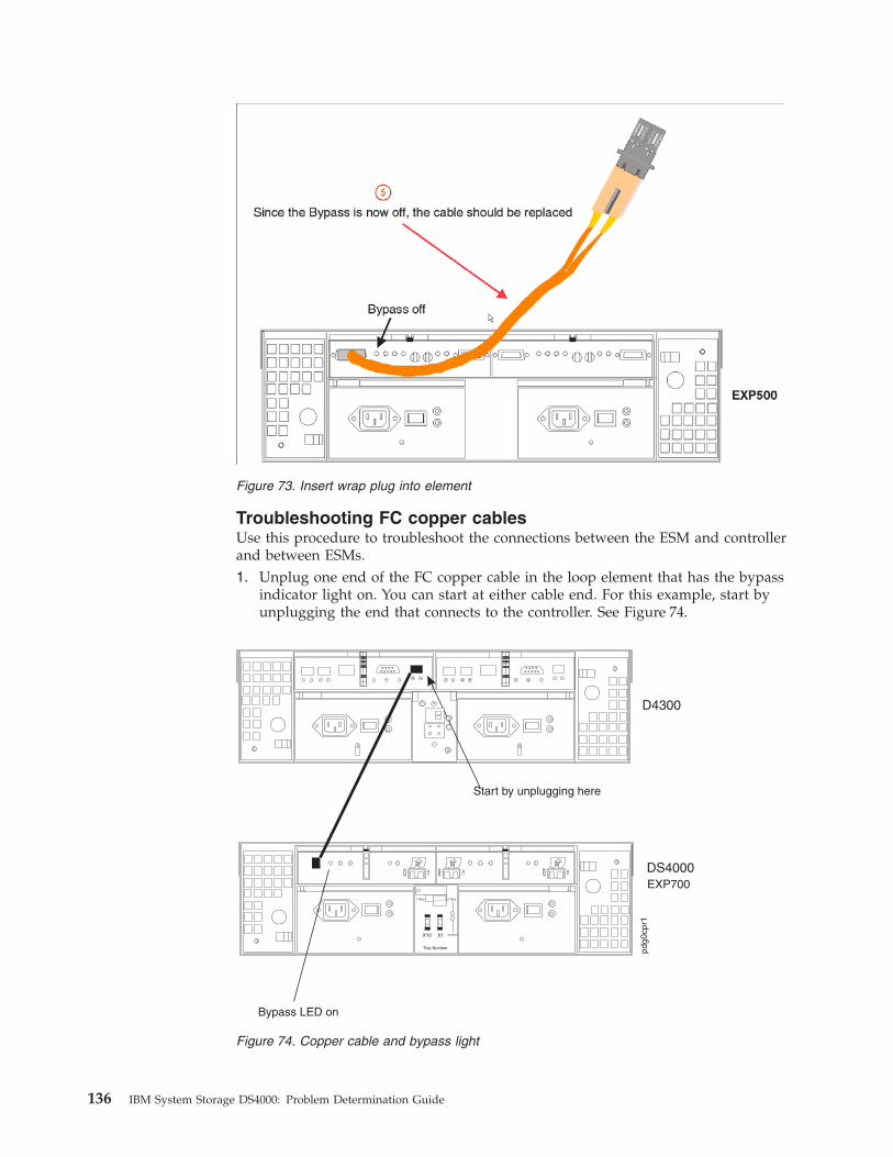
Troubleshooting FC copper cables
Use this procedure to troubleshoot the connections between the ESM and controller
and between ESMs.
1. Unplug one end of the FC copper cable in the loop element that has the bypass
indicator light on. You can start at either cable end. For this example, start by
unplugging the end that connects to the controller. See Figure 74.
Figure 73. Insert wrap plug into element
Figure 74. Copper cable and bypass light
136 IBM System Storage DS4000: Problem Determination Guide
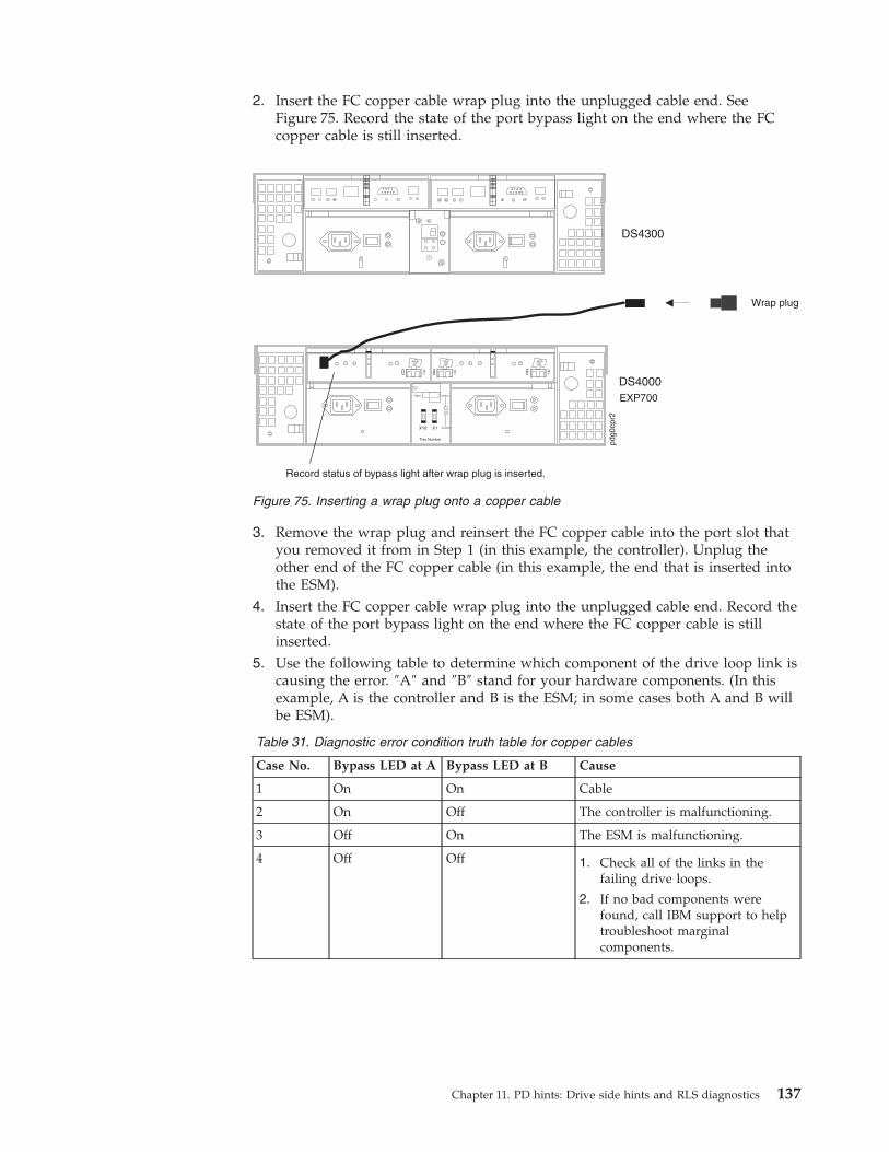
2. Insert the FC copper cable wrap plug into the unplugged cable end. See
Figure 75. Record the state of the port bypass light on the end where the FC
copper cable is still inserted.
3. Remove the wrap plug and reinsert the FC copper cable into the port slot that
you removed it from in Step 1 (in this example, the controller). Unplug the
other end of the FC copper cable (in this example, the end that is inserted into
the ESM).
4. Insert the FC copper cable wrap plug into the unplugged cable end. Record the
state of the port bypass light on the end where the FC copper cable is still
inserted.
5. Use the following table to determine which component of the drive loop link is
causing the error. ″A″ and ″B″ stand for your hardware components. (In this
example, A is the controller and B is the ESM; in some cases both A and B will
be ESM).
Table 31. Diagnostic error condition truth table for copper cables
Case No. Bypass LED at A Bypass LED at B Cause
1 On On Cable
2 On Off The controller is malfunctioning.
3 Off On The ESM is malfunctioning.
4 Off Off 1. Check all of the links in the
failing drive loops.
2. If no bad components were
found, call IBM support to help
troubleshoot marginal
components.
Figure 75. Inserting a wrap plug onto a copper cable
Chapter 11. PD hints: Drive side hints and RLS diagnostics 137
Read Link Status (RLS) Diagnostics
A fibre channel loop is an interconnection topology used to connect storage
subsystem components and devices. The DS4000 Storage Manager Version 8 or
later software uses the connection between the host machine and each controller in
the storage subsystem to communicate with each component and device on the
loop.
During communication between devices, Read Link Status (RLS) error counts are
detected within the traffic flow of the loop. Error count information is accumulated
over a period of time for every component and device including:
v Drives
v ESMs
v Fibre channel ports
Error counts are calculated from a baseline, which describes the error count values
for each type of device in the fibre channel loop. Calculation occurs from the time
when the baseline was established to the time at which the error count information
is requested.
The baseline is automatically set by the controller. However, a new baseline can be
set manually in the Read Link Status Diagnostics window. For more information,
see “How to set the baseline” on page 140.
Overview
Read Link Status error counts refer to link errors that have been detected in the
traffic flow of a fibre channel loop. The errors detected are represented as a count
(32-bit field) of error occurrences accumulated over time. The errors help to
provide a coarse measure of the integrity of the components and devices on the
loop.
The Read Link Status Diagnostics window retrieves the error counts and displays
the controllers, drives, ESMs, and fibre channel ports in channel order.
By analyzing the error counts retrieved, it is possible to determine the components
or devices within the fibre channel loop which might be experiencing problems
communicating with the other devices on the loop. A high error count for a
particular component or device indicates that it might be experiencing problems,
and should be given immediate attention.
Error counts are calculated from the current baseline and can be reset by defining a
new baseline.
Analyzing RLS Results
Analysis of the RLS error count data is based on the principle that the device
immediately ″downstream″ of the problematic component should see the largest
number of Invalid Transmission Word (ITW) error counts.
Note: Because the current error counting standard is vague about when the ITW
count is calculated, different vendors’ devices calculate errors at different
rates. Analysis of the data must take this into account.
The analysis process involves obtaining an ITW error count for every component
and device on the loop, viewing the data in loop order, and then identifying any
138 IBM System Storage DS4000: Problem Determination Guide
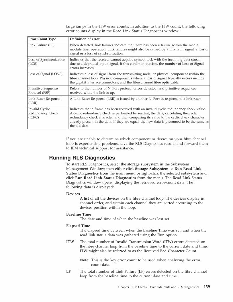
large jumps in the ITW error counts. In addition to the ITW count, the following
error counts display in the Read Link Status Diagnostics window:
Error Count Type Definition of error
Link Failure (LF) When detected, link failures indicate that there has been a failure within the media
module laser operation. Link failures might also be caused by a link fault signal, a loss of
signal or a loss of synchronization.
Loss of Synchronization
(LOS)
Indicates that the receiver cannot acquire symbol lock with the incoming data stream,
due to a degraded input signal. If this condition persists, the number of Loss of Signal
errors increases.
Loss of Signal (LOSG) Indicates a loss of signal from the transmitting node, or physical component within the
fibre channel loop. Physical components where a loss of signal typically occurs include
the gigabit interface connectors, and the fibre channel fibre optic cable.
Primitive Sequence
Protocol (PSP)
Refers to the number of N_Port protocol errors detected, and primitive sequences
received while the link is up.
Link Reset Response
(LRR)
A Link Reset Response (LRR) is issued by another N_Port in response to a link reset.
Invalid Cyclic
Redundancy Check
(ICRC)
Indicates that a frame has been received with an invalid cyclic redundancy check value.
A cyclic redundancy check is performed by reading the data, calculating the cyclic
redundancy check character, and then comparing its value to the cyclic check character
already present in the data. If they are equal, the new data is presumed to be the same as
the old data.
If you are unable to determine which component or device on your fibre channel
loop is experiencing problems, save the RLS Diagnostics results and forward them
to IBM technical support for assistance.
Running RLS Diagnostics
To start RLS Diagnostics, select the storage subsystem in the Subsystem
Management Window; then either click Storage Subsystem -> Run Read Link
Status Diagnostics from the main menu or right-click the selected subsystem and
click Run Read Link Status Diagnostics from the menu. The Read Link Status
Diagnostics window opens, displaying the retrieved error-count data. The
following data is displayed:
Devices
A list of all the devices on the fibre channel loop. The devices display in
channel order, and within each channel they are sorted according to the
devices position within the loop.
Baseline Time
The date and time of when the baseline was last set.
Elapsed Time
The elapsed time between when the Baseline Time was set, and when the
read link status data was gathered using the Run option.
ITW The total number of Invalid Transmission Word (ITW) errors detected on
the fibre channel loop from the baseline time to the current date and time.
ITW might also be referred to as the Received Bad Character Count.
Note: This is the key error count to be used when analyzing the error
count data.
LF The total number of Link Failure (LF) errors detected on the fibre channel
loop from the baseline time to the current date and time.
Chapter 11. PD hints: Drive side hints and RLS diagnostics 139

LOS The total number of Loss of Synchronization (LOS) errors detected on the
fibre channel loop from the baseline time to the current date and time.
LOSG The total number of Loss of Signal (LOSG) errors detected on the fibre
channel loop from the baseline date to the current date and time.
PSP The total number of Primitive Sequence Protocol (PSP) errors detected on
the fibre channel loop from the baseline date to the current date and time.
ICRC The total number of Invalid Cyclic Redundancy Check (ICRC) errors
detected on the fibre channel loop, from the baseline date to the current
date and time.
How to set the baseline
Error counts are calculated from a baseline (which describes the error count values
for each type of device in the fibre channel loop), from the time when the baseline
was established to the time at which the error count information is requested.
The baseline is automatically set by the controller; however, a new baseline can be
set manually in the Read Link Status Diagnostics window using the following
steps:
Note: This option establishes new baseline error counts for ALL devices currently
initialized on the loop.
1. Click Set Baseline. A confirmation window opens.
2. Click Yes to confirm baseline change. If the new baseline is successfully set, a
success message is displayed indicating that the change has been made.
3. Click OK. The Read Link Status Diagnostics window opens.
4. Click Run to retrieve the current error counts.
How to interpret results
To interpret RLS results, perform the following actions:
1. Open the Read Link Status Diagnostics window.
2. Review the ITW column in the Read Link Status Diagnostics window and
identify any unusual increase in the ITW counts.
Example:
The following shows the typical error-count information displayed in the Read
Link Status Diagnostics window. In this example, the first window contains a
list of the values after setting the baseline. The RLS diagnostic is run a short
time later, and the result shows an increase in error counts at Controller B. This
is probably due to either the drive right before (2/9), or more likely the ESM
(Drive enclosure 2).
Figure 76 on page 141 shows the RLS Status after setting the baseline.
140 IBM System Storage DS4000: Problem Determination Guide

Figure 77 shows the RLS Status after running the diagnostic.
Note: This is only an example and is not applicable to all situations.
Important: Because the current error counting standard is vague about when
the ITW error count is calculated, different vendor’s devices calculate at
different rates. Analysis of the data must take this into account.
3. Click Close to return to the Subsystem Management window, and troubleshoot
the problematic devices. If you are unable to determine what component is
problematic, save your results and forward them to IBM technical support.
How to save Diagnostics results
For further troubleshooting assistance, save the Read Link Status results and
forward them to technical support for assistance.
1. Click Save As. The Save As window opens.
Figure 76. RLS Status after setting baseline
Figure 77. RLS Status after diagnostic
Chapter 11. PD hints: Drive side hints and RLS diagnostics 141

2. Select a directory and type the file name of your choice in the File name field.
You do not need to specify a file extension.
3. Click Save. A comma-delimited file containing the read link status results is
saved.
142 IBM System Storage DS4000: Problem Determination Guide

Chapter 12. PD hints: Hubs and switches
You should be referred to this chapter from a PD map or indication. If this is not
the case, refer back to Chapter 2, “Problem determination starting points,” on page
3.
After you have read the relevant information in this chapter, return to the PD map
that directed you here, either “Hub/Switch PD map 2” on page 14 or “Common
Path PD map 2” on page 21.
Unmanaged hub
The unmanaged hub is used only with the type 3526 RAID controller. This hub
does not contain any management or debugging aids other than the LEDs that
give an indicator of port up or down.
Switch and managed hub
The switch and managed hub are used with FAStT500, FAStT200, DS4400, DS4500,
DS4300, and DS4100 controllers. The following sections describe tests that can be
used with the switch and managed hub.
Note: The following test commands apply specifically to the IBM SAN Fibre
Channel Switch 2109 Model S16. The tests commands for your switch might
differ slightly. Refer to your switch documentation for details.
Running crossPortTest
The crossPortTest verifies the intended functional operation of the switch and
managed hub by sending frames from the transmitter for each port by way of the
GBIC or fixed port and external cable to another port’s receiver. By sending these
frames, the crossPortTest exercises the entire path of the switch and managed
hub.
A port can be connected to any other port in the same switch or managed hub,
provided that the connection is of the same technology. This means that ShortWave
ports can only be connected to ShortWave ports; LongWave ports can be connected
only to LongWave ports.
Note: An error condition will be shown for any ports that are on the switch or
managed hub but that are not connected. If you want more information on
the crossPortTest and its options, see the Installation and Service Guide for
the switch or managed hub you are using.
To repeat the results in the following examples, run the tests in online mode and
with the singlePortAlso mode enabled. The test will run continuously until your
press the Return key on the console being used to perform Ethernet connected
management of the switch or managed hub.
To run, the test must find at least one port with a wrap plug or two ports
connected to each other. If one of these criteria is not met, the test results in the
following message in the telnet shell:
Need at least 1 port(s) connected to run this test.
© Copyright IBM Corp. 2006 143
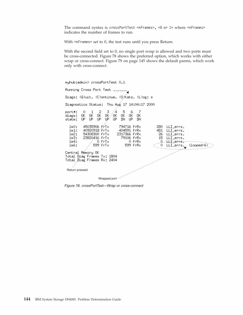
The command syntax is crossPortTest <nFrames>, <0 or 1> where <nFrames>
indicates the number of frames to run.
With <nFrames> set to 0, the test runs until you press Return.
With the second field set to 0, no single port wrap is allowed and two ports must
be cross-connected. Figure 78 shows the preferred option, which works with either
wrap or cross-connect. Figure 79 on page 145 shows the default parms, which work
only with cross-connect.
Return pressed
Wrapped port
Figure 78. crossPortTest—Wrap or cross-connect
144 IBM System Storage DS4000: Problem Determination Guide
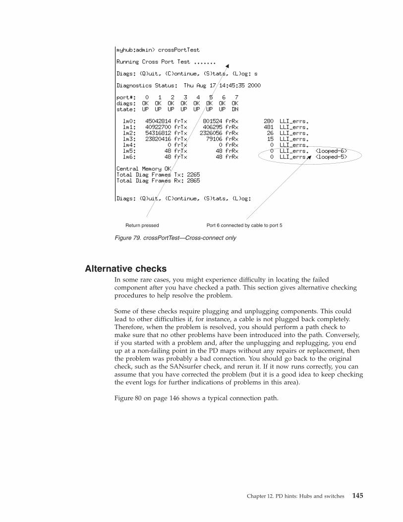
Alternative checks
In some rare cases, you might experience difficulty in locating the failed
component after you have checked a path. This section gives alternative checking
procedures to help resolve the problem.
Some of these checks require plugging and unplugging components. This could
lead to other difficulties if, for instance, a cable is not plugged back completely.
Therefore, when the problem is resolved, you should perform a path check to
make sure that no other problems have been introduced into the path. Conversely,
if you started with a problem and, after the unplugging and replugging, you end
up at a non-failing point in the PD maps without any repairs or replacement, then
the problem was probably a bad connection. You should go back to the original
check, such as the SANsurfer check, and rerun it. If it now runs correctly, you can
assume that you have corrected the problem (but it is a good idea to keep checking
the event logs for further indications of problems in this area).
Figure 80 on page 146 shows a typical connection path.
Return pressed Port 6 connected by cable to port 5
Figure 79. crossPortTest—Cross-connect only
Chapter 12. PD hints: Hubs and switches 145
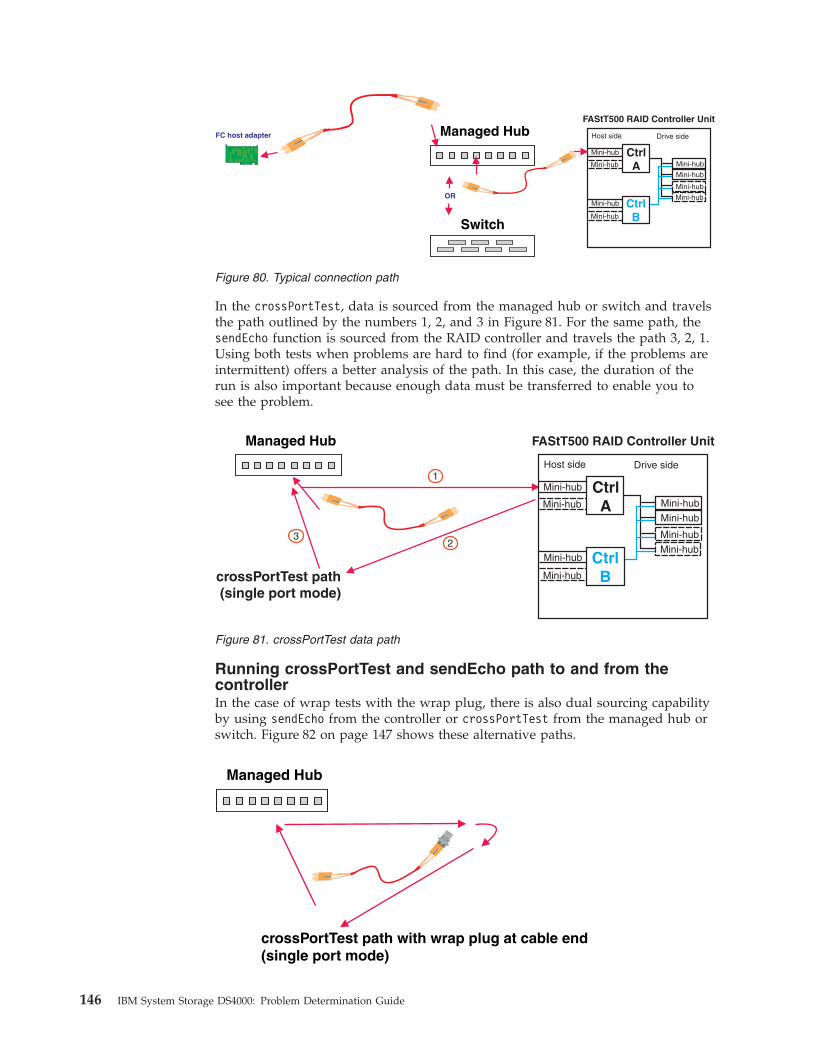
In the crossPortTest, data is sourced from the managed hub or switch and travels
the path outlined by the numbers 1, 2, and 3 in Figure 81. For the same path, the
sendEcho function is sourced from the RAID controller and travels the path 3, 2, 1.
Using both tests when problems are hard to find (for example, if the problems are
intermittent) offers a better analysis of the path. In this case, the duration of the
run is also important because enough data must be transferred to enable you to
see the problem.
Running crossPortTest and sendEcho path to and from the
controller
In the case of wrap tests with the wrap plug, there is also dual sourcing capability
by using sendEcho from the controller or crossPortTest from the managed hub or
switch. Figure 82 on page 147 shows these alternative paths.
Managed Hub
crossPortTest path with wrap plug at cable end(single port mode)
Mini-hub
Host side
Mini-hub
Mini-hub
Mini-hub
FAStT500 RAID Controller Unit
CtrlB
CtrlA
Mini-hub
Mini-hub
Mini-hub
Mini-hub
Drive sideManaged Hub
Switch
FC host adapter
OR
Figure 80. Typical connection path
crossPortTest path(single port mode)
1
23
Managed Hub
Mini-hub
Host side
Mini-hub
Mini-hub
Mini-hub
FAStT500 RAID Controller Unit
CtrlB
CtrlA
Mini-hub
Mini-hub
Mini-hub
Mini-hub
Drive side
Figure 81. crossPortTest data path
146 IBM System Storage DS4000: Problem Determination Guide
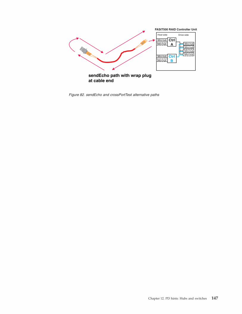
sendEcho path with wrap plugat cable end
Mini-hub
Host side
Mini-hub
Mini-hub
Mini-hub
FAStT500 RAID Controller Unit
CtrlB
CtrlA
Mini-hub
Mini-hub
Mini-hub
Mini-hub
Drive side
Figure 82. sendEcho and crossPortTest alternative paths
Chapter 12. PD hints: Hubs and switches 147

148 IBM System Storage DS4000: Problem Determination Guide

Chapter 13. PD hints: Wrap plug tests
You should be referred to this chapter from a PD map or indication. If this is not
the case, refer back to Chapter 2, “Problem determination starting points,” on page
3.
After you have read the relevant information in this chapter, return to “Single Path
Fail PD map 1” on page 18.
The following sections illustrate the use of wrap plugs.
Running sendEcho and crossPortTest path to and from controller
Mini-hub
Host side
Mini-hub
Mini-hub
Mini-hub
FAStT500 RAID Controller Unit
CtrlB
CtrlA
Mini-hub
Mini-hub
Mini-hub
Mini-hub
Drive side
Failed path of read/write buffer test
Install wrap plug to GBIC on mini-hubof controller A
Figure 83. Install wrap plug to GBIC
© Copyright IBM Corp. 2006 149
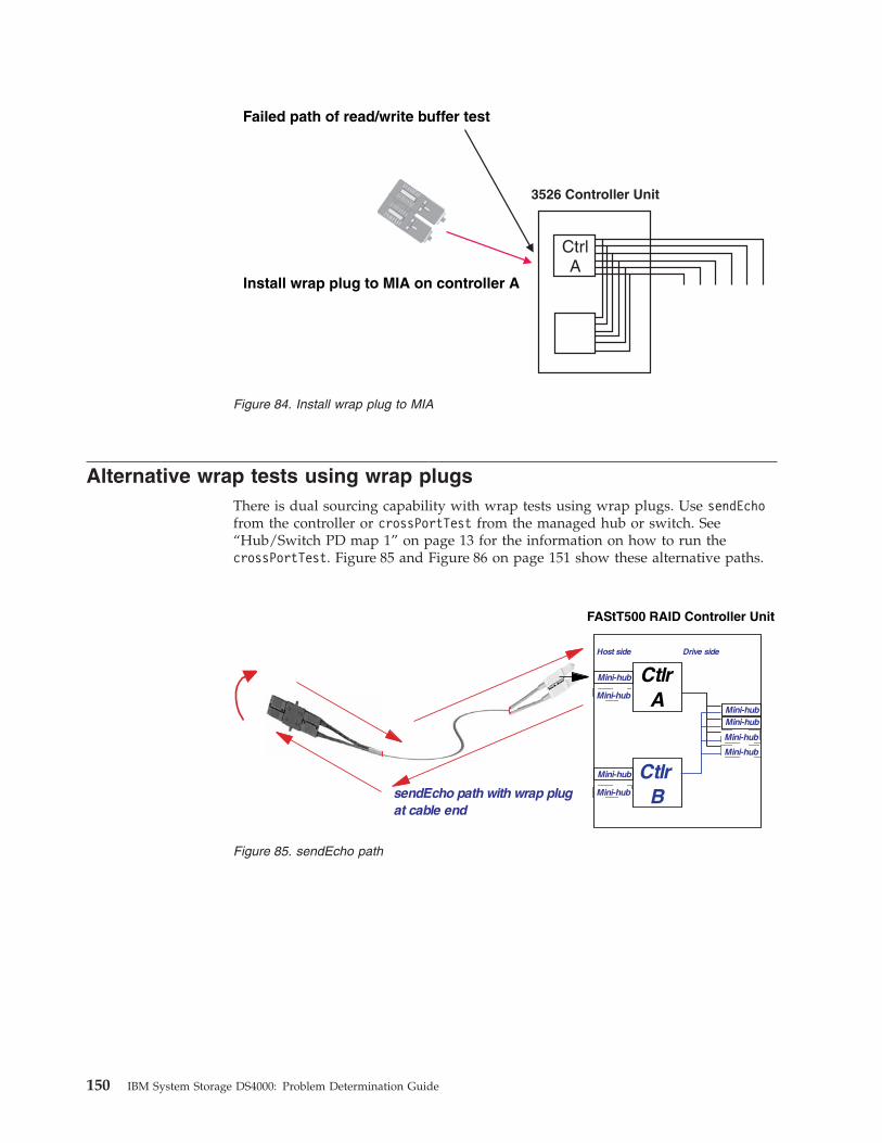
Alternative wrap tests using wrap plugs
There is dual sourcing capability with wrap tests using wrap plugs. Use sendEcho
from the controller or crossPortTest from the managed hub or switch. See
“Hub/Switch PD map 1” on page 13 for the information on how to run the
crossPortTest. Figure 85 and Figure 86 on page 151 show these alternative paths.
3526 Controller Unit
Failed path of read/write buffer test
Install wrap plug to MIA on controller A
CtrlA
Figure 84. Install wrap plug to MIA
FAStT500 RAID Controller Unit
CtlrB
CtlrA
Mini-hub
Host side Drive side
Mini-hub
Mini-hubMini-hub
Mini-hub
Mini-hub
Mini-hub
Mini-hub
sendEcho path with wrap plugat cable end
Figure 85. sendEcho path
150 IBM System Storage DS4000: Problem Determination Guide

Managed Hub
crossPortTest path with wrap plug at cable end(single port mode)
Figure 86. crossPortTest path
Chapter 13. PD hints: Wrap plug tests 151

152 IBM System Storage DS4000: Problem Determination Guide
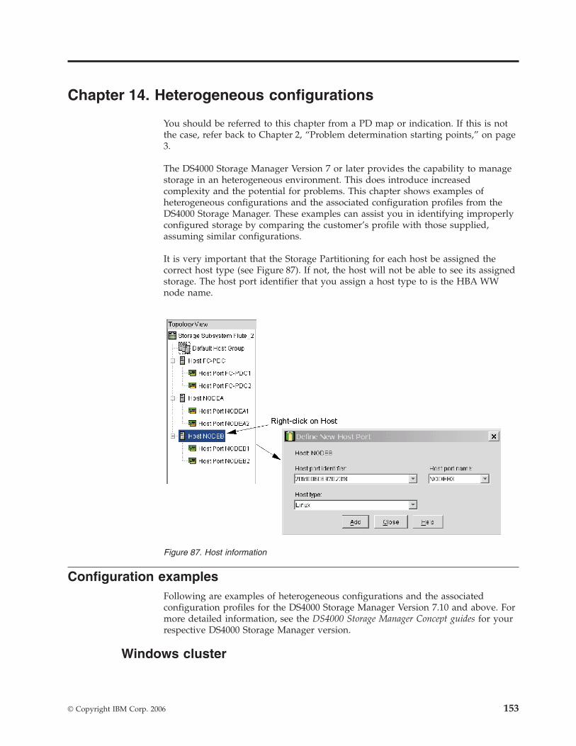
Chapter 14. Heterogeneous configurations
You should be referred to this chapter from a PD map or indication. If this is not
the case, refer back to Chapter 2, “Problem determination starting points,” on page
3.
The DS4000 Storage Manager Version 7 or later provides the capability to manage
storage in an heterogeneous environment. This does introduce increased
complexity and the potential for problems. This chapter shows examples of
heterogeneous configurations and the associated configuration profiles from the
DS4000 Storage Manager. These examples can assist you in identifying improperly
configured storage by comparing the customer’s profile with those supplied,
assuming similar configurations.
It is very important that the Storage Partitioning for each host be assigned the
correct host type (see Figure 87). If not, the host will not be able to see its assigned
storage. The host port identifier that you assign a host type to is the HBA WW
node name.
Configuration examples
Following are examples of heterogeneous configurations and the associated
configuration profiles for the DS4000 Storage Manager Version 7.10 and above. For
more detailed information, see the DS4000 Storage Manager Concept guides for your
respective DS4000 Storage Manager version.
Windows cluster
Figure 87. Host information
© Copyright IBM Corp. 2006 153
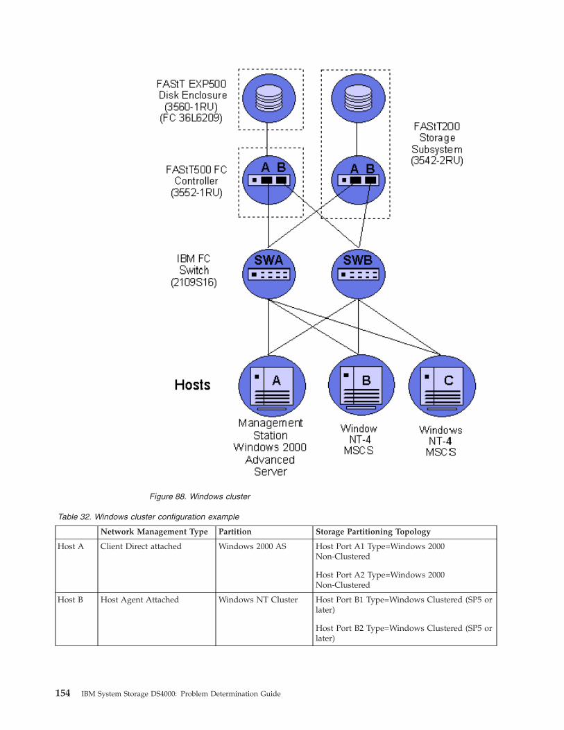
Table 32. Windows cluster configuration example
Network Management Type Partition Storage Partitioning Topology
Host A Client Direct attached Windows 2000 AS Host Port A1 Type=Windows 2000
Non-Clustered
Host Port A2 Type=Windows 2000
Non-Clustered
Host B Host Agent Attached Windows NT Cluster Host Port B1 Type=Windows Clustered (SP5 or
later)
Host Port B2 Type=Windows Clustered (SP5 or
later)
Figure 88. Windows cluster
154 IBM System Storage DS4000: Problem Determination Guide

Table 32. Windows cluster configuration example (continued)
Network Management Type Partition Storage Partitioning Topology
Host C Host Agent Attached Windows NT Cluster Host Port C1 Type=Windows Clustered (SP5 or
higher)
Host Port C2 Type=Windows Clustered (SP5 or
higher)
Heterogeneous configuration
Table 33. Heterogeneous configuration example
Network Management Type Partition Storage Partitioning Topology
Host A Client Direct attached Windows 2000 AS Host Port A1 Type=Windows 2000
Non-Clustered
Host Port A2 Type=Windows 2000
Non-Clustered
Host B Host Agent Attached Windows 2000 Cluster Host Port B1 Type=Windows Clustered
Host Port B2 Type=Windows Clustered
Host C Host Agent Attached Windows 2000 Cluster Host Port C1 Type=Windows Clustered
Host Port C2 Type=Windows Clustered
Host D Host Agent Attached NetWare Host Port D1/ Type=NetWare
Host Port D2/Type=NetWare
Figure 89. Heterogeneous configuration
Chapter 14. Heterogeneous configurations 155

Table 33. Heterogeneous configuration example (continued)
Network Management Type Partition Storage Partitioning Topology
Host E Host Agent Attached Linux Host Port E1/ Type=Linux
Host Port E2/Type=Linux
Host F Host Agent Attached Windows NT Host Port F1/Type=Windows NT
Host Port F2/ Type=Windows NT
156 IBM System Storage DS4000: Problem Determination Guide

Chapter 15. Using the IBM Fast!UTIL utility
This chapter provides detailed configuration information for advanced users who
want to customize the configuration of the following adapters:
v IBM fibre-channel PCI adapter (FRU 01K7354)
v IBM DS4000 host adapter (FRU 09N7292)
v IBM DS4000 FC2-133 host bus adapter (FRU 24P0962)
For more information about these adapters, see the IBM System Storage™; DS4000
Hardware Maintenance Manual.
You can configure the adapters and the connected fibre channel devices using the
Fast!UTIL utility.
Attention: The IBM Fast!UTIL utility is not available on IBM BladeCenter®
models.
Starting the Fast!UTIL utility
To access the Fast!UTIL utility, press Ctrl+Q (or Alt+Q for 2100) during the adapter
BIOS initialization (it might take a few seconds for the Fast!UTIL menu to display).
If you have more than one adapter, the Fast!UTIL utility prompts you to select the
adapter you want to configure. After changing the settings, the Fast!UTIL utility
restarts your system to load the new parameters.
Important: If the configuration settings are incorrect, your adapter will not
function properly. Do not modify the default configuration settings unless you are
instructed to do so by an IBM support representative or the installation
instructions. The default settings are for a typical Microsoft Windows installation.
See the adapter driver readme file for the appropriate operating system for
required NVRAM setting modifications for that operating system.
Fast!UTIL options
This section describes the Fast!UTIL options. The first option on the Fast!UTIL
Options menu is Configuration Settings. The settings configure the fibre-channel
devices and the adapter to which they are attached.
Note: If your version of the Fast!UTIL utility has settings that are not discussed in
this section, then you are working with down-level BIOS or non-supported
BIOS. Update your BIOS version.
Host adapter settings
You can use this option to modify host adapter settings. The current default
settings for the host adapters are described in this section.
Note: All settings for the IBM fibre-channel PCI adapter (FRU 01K7354) are
accessed from the Host Adapter Settings menu option (see Table 34 on page
158). The DS4000 host adapter (FRU 09N7292) and the DS4000 FC2-133 host
bus adapter (FRU 24P0962) offer additional settings available from the
Advanced Adapter Settings menu option (see Table 35 on page 158 and
© Copyright IBM Corp. 2006 157

Table 36). Any settings for the fibre-channel PCI adapter (FRU 01K7354) not
described in this section are described in “Advanced adapter settings” on
page 160.
Table 34. IBM fibre-channel PCI adapter (FRU 01K7354) host adapter settings
Setting Options Default
Host adapter BIOS Enabled or Disabled Disabled
Execution throttle 1 - 256 256
Frame size 512, 1024, 2048 2048
Loop reset delay 0-15 seconds 8 seconds
Extended error logging Enabled or Disabled Disabled
Port down retry count 0-255 30
Table 35. DS4000 host adapter (FRU 09N7292) host adapter settings
Setting Options Default
Host adapter BIOS Enabled or Disabled Disabled
Frame size 512, 1024, 2048 2048
Loop reset delay 0-15 seconds 5 seconds
Adapter hard loop ID Enabled or Disabled Enabled
Hard loop ID 0-125 125
Connection Options 0, 1, 2, 3 3
Fibre channel tape support Enabled or Disabled Disabled
Table 36. DS4000 FC2-133 (FRU 24P0962) host bus adapter host adapter settings
Setting Options Default
Host adapter BIOS Enabled or Disabled Disabled
Frame size 512, 1024, 2048 2048
Loop reset delay 0-60 seconds 5 seconds
Adapter hard loop ID Enabled or Disabled Enabled
Hard loop ID 0-125 125
Spin up delay Enabled or Disabled Disabled
Connection Options 0, 1, 2, 3 2
Fibre channel tape support Enabled or Disabled Disabled
Data rate [for DS4000 FC2-133
host bus adapter (FRU
24P0962) only]
0, 1, 2 2
Host adapter BIOS
When this option is set to Disabled, the ROM BIOS code on the adapter is
disabled, freeing space in upper memory. This setting must be enabled if
you are starting from a fibre channel hard disk that is attached to the
adapter. The default is Disabled.
Frame size
This setting specifies the maximum frame length supported by the adapter.
The default size is 2048. If you are using F-Port (point-to-point)
connections, the default is best for maximum performance.
158 IBM System Storage DS4000: Problem Determination Guide
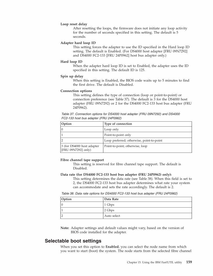
Loop reset delay
After resetting the loops, the firmware does not initiate any loop activity
for the number of seconds specified in this setting. The default is 5
seconds.
Adapter hard loop ID
This setting forces the adapter to use the ID specified in the Hard loop ID
setting. The default is Enabled. (For DS4000 host adapter [FRU 09N7292]
and DS4000 FC2-133 [FRU 24P0962] host bus adapter only.)
Hard loop ID
When the adapter hard loop ID is set to Enabled, the adapter uses the ID
specified in this setting. The default ID is 125.
Spin up delay
When this setting is Enabled, the BIOS code waits up to 5 minutes to find
the first drive. The default is Disabled.
Connection options
This setting defines the type of connection (loop or point-to-point) or
connection preference (see Table 37). The default is 3 for the DS4000 host
adapter (FRU 09N7292) or 2 for the DS4000 FC2-133 host bus adapter (FRU
24P0962).
Table 37. Connection options for DS4000 host adapter (FRU 09N7292) and DS4000
FC2-133 host bus adapter (FRU 24P0962)
Option Type of connection
0 Loop only
1 Point-to-point only
2 Loop preferred; otherwise, point-to-point
3 (for DS4000 host adapter
[FRU 09N7292] only)
Point-to-point; otherwise, loop
Fibre channel tape support
This setting is reserved for fibre channel tape support. The default is
Disabled.
Data rate (for DS4000 FC2-133 host bus adapter (FRU 24P0962) only):
This setting determines the data rate (see Table 38). When this field is set to
2, the DS4000 FC2-133 host bus adapter determines what rate your system
can accommodate and sets the rate accordingly. The default is 2.
Table 38. Data rate options for DS4000 FC2-133 host bus adapter (FRU 24P0962)
Option Data Rate
0 1 Gbps
1 2 Gbps
2 Auto select
Note: Adapter settings and default values might vary, based on the version of
BIOS code installed for the adapter.
Selectable boot settings
When you set this option to Enabled, you can select the node name from which
you want to start (boot) the system. The node starts from the selected fibre channel
Chapter 15. Using the IBM Fast!UTIL utility 159
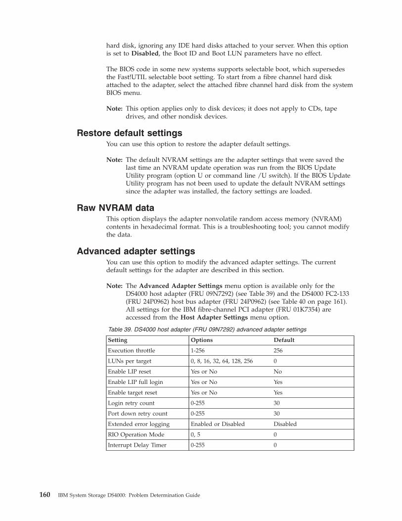
hard disk, ignoring any IDE hard disks attached to your server. When this option
is set to Disabled, the Boot ID and Boot LUN parameters have no effect.
The BIOS code in some new systems supports selectable boot, which supersedes
the Fast!UTIL selectable boot setting. To start from a fibre channel hard disk
attached to the adapter, select the attached fibre channel hard disk from the system
BIOS menu.
Note: This option applies only to disk devices; it does not apply to CDs, tape
drives, and other nondisk devices.
Restore default settings
You can use this option to restore the adapter default settings.
Note: The default NVRAM settings are the adapter settings that were saved the
last time an NVRAM update operation was run from the BIOS Update
Utility program (option U or command line /U switch). If the BIOS Update
Utility program has not been used to update the default NVRAM settings
since the adapter was installed, the factory settings are loaded.
Raw NVRAM data
This option displays the adapter nonvolatile random access memory (NVRAM)
contents in hexadecimal format. This is a troubleshooting tool; you cannot modify
the data.
Advanced adapter settings
You can use this option to modify the advanced adapter settings. The current
default settings for the adapter are described in this section.
Note: The Advanced Adapter Settings menu option is available only for the
DS4000 host adapter (FRU 09N7292) (see Table 39) and the DS4000 FC2-133
(FRU 24P0962) host bus adapter (FRU 24P0962) (see Table 40 on page 161).
All settings for the IBM fibre-channel PCI adapter (FRU 01K7354) are
accessed from the Host Adapter Settings menu option.
Table 39. DS4000 host adapter (FRU 09N7292) advanced adapter settings
Setting Options Default
Execution throttle 1-256 256
LUNs per target 0, 8, 16, 32, 64, 128, 256 0
Enable LIP reset Yes or No No
Enable LIP full login Yes or No Yes
Enable target reset Yes or No Yes
Login retry count 0-255 30
Port down retry count 0-255 30
Extended error logging Enabled or Disabled Disabled
RIO Operation Mode 0, 5 0
Interrupt Delay Timer 0-255 0
160 IBM System Storage DS4000: Problem Determination Guide

Table 40. DS4000 FC2-133 (FRU 24P0962) host bus adapter advanced adapter settings
Setting Options Default
Execution throttle 1-256 256
LUNs per target 0, 8, 16, 32, 64, 128, 256 0
Enable LIP reset Yes or No No
Enable LIP full login Yes or No Yes
Enable target reset Yes or No Yes
Login retry count 0-255 30
Port down retry count 0-255 30
Extended error logging Enabled or Disabled Disabled
RIO Operation Mode 0, 5 0
Interrupt Delay Timer 0-255 0
Execution throttle
This setting specifies the maximum number of commands running on any
one port. When a port reaches its execution throttle, the Fast!UTIL utility
does not run any new commands until the current command is completed.
The valid options for this setting are 1 through 256. The default (optimum)
is 256.
LUNs per target (for IBM fibre-channel PCI adapter [FRU 01K7354])
This setting specifies the number of LUNs per target. Multiple logical unit
number (LUN) support is typically for redundant array of independent
disks (RAID) enclosures that use LUNs to map drives. The default is 8. For
NetWare, set the number of LUNs to 32.
LUNs per target (for DS4000 host adapter [FRU 09N7292] and DS4000 FC2-133
host bus adapter [FRU 24P0962]
This setting specifies the number of LUNs per target. Multiple logical unit
number (LUN) support is typically for redundant array of independent
disks (RAID) enclosures that use LUNs to map drives. The default is 0. For
NetWare, set the number of LUNs to 32.
Enable LIP reset
This setting determines the type of loop initialization process (LIP) reset
that is used when the operating system initiates a bus reset routine. When
this option is set to Yes, the device driver initiates a global LIP reset to
clear the target device reservations. When this option is set to No, the
device driver initiates a global LIP reset with full login. The default is No.
Enable LIP full logon
This setting instructs the ISP chip to log into all ports after any LIP. The
default is Yes.
Enable target reset
This setting enables the device drivers to issue a Target Reset command to
all devices on the loop when a SCSI Bus Reset command is issued. The
default is Yes.
Login retry count
This setting specifies the number of times the software tries to log in to a
device. The default is 30 retries.
Chapter 15. Using the IBM Fast!UTIL utility 161
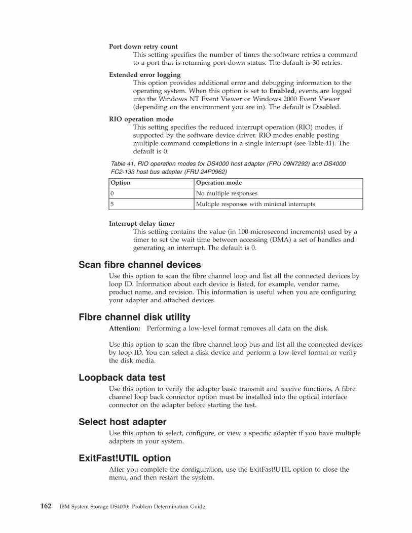
Port down retry count
This setting specifies the number of times the software retries a command
to a port that is returning port-down status. The default is 30 retries.
Extended error logging
This option provides additional error and debugging information to the
operating system. When this option is set to Enabled, events are logged
into the Windows NT Event Viewer or Windows 2000 Event Viewer
(depending on the environment you are in). The default is Disabled.
RIO operation mode
This setting specifies the reduced interrupt operation (RIO) modes, if
supported by the software device driver. RIO modes enable posting
multiple command completions in a single interrupt (see Table 41). The
default is 0.
Table 41. RIO operation modes for DS4000 host adapter (FRU 09N7292) and DS4000
FC2-133 host bus adapter (FRU 24P0962)
Option Operation mode
0 No multiple responses
5 Multiple responses with minimal interrupts
Interrupt delay timer
This setting contains the value (in 100-microsecond increments) used by a
timer to set the wait time between accessing (DMA) a set of handles and
generating an interrupt. The default is 0.
Scan fibre channel devices
Use this option to scan the fibre channel loop and list all the connected devices by
loop ID. Information about each device is listed, for example, vendor name,
product name, and revision. This information is useful when you are configuring
your adapter and attached devices.
Fibre channel disk utility
Attention: Performing a low-level format removes all data on the disk.
Use this option to scan the fibre channel loop bus and list all the connected devices
by loop ID. You can select a disk device and perform a low-level format or verify
the disk media.
Loopback data test
Use this option to verify the adapter basic transmit and receive functions. A fibre
channel loop back connector option must be installed into the optical interface
connector on the adapter before starting the test.
Select host adapter
Use this option to select, configure, or view a specific adapter if you have multiple
adapters in your system.
ExitFast!UTIL option
After you complete the configuration, use the ExitFast!UTIL option to close the
menu, and then restart the system.
162 IBM System Storage DS4000: Problem Determination Guide
Chapter 16. Frequently asked questions about the DS4000
Storage Manager
This chapter contains answers to frequently asked questions (FAQs) in the
following areas:
v “Global Hot Spare (GHS) drives”
v “Auto Code Synchronization (ACS)” on page 166
v “Storage partitioning” on page 169
v “Miscellaneous” on page 170
Global Hot Spare (GHS) drives
What is a Global Hot Spare?
A Global Hot Spare is a drive within the storage subsystem that has been defined
by the user as a spare drive. The Global Hot Spare is to be used in the event that a
drive that is part of an array with redundancy (RAID 1, 3, 5 array) fails. When the
fail occurs, and a GHS drive is configured, the controller will begin reconstructing
to the GHS drive. Once the reconstruction to the GHS drive is complete, the array
will be promoted from the Degraded state to the Optimal state, thus providing full
redundancy again. When the failed drive is replaced with a good drive, the
copyback process will start automatically.
What is reconstruction and copyback?
Reconstruction is the process of reading data from the remaining drive (or drives)
of an array that has a failed drive and writing that data to the GHS drive.
Copyback is the process of copying the data from the GHS drive to the drive that
has replaced the failed drive.
What happens during the reconstruction of the GHS?
During the reconstruction process, data is read from the remaining drive (or
drives) within the array and used to reconstruct the data on the GHS drive.
How long does the reconstruction process take?
The time to reconstruct a GHS drive will vary depending on the activity on the
array, the size of the failed array, and the speed of the drives.
What happens if a GHS drive fails while sparing for a failed drive?
If a GHS drive fails while it is sparing for another drive, and another GHS is
configured in the array, a reconstruction process to another GHS will be done.
If a GHS fails, and a second GHS is used, and both the originally failed drive
and the failed GHS drive are replaced at the same time, how will the copyback
be done?
© Copyright IBM Corp. 2006 163

The controller will know which drive is being spared by the GHS, even in the
event that the first GHS failed and a second GHS was used. When the original
failed drive is replaced, the copyback process will begin from the second GHS.
If the size of the failed drive is 9Gbyte, but only 3Gbytes of data have been
written to the drive, and the GHS is an 18Gbyte drive, how much is
reconstructed?
The size of the array determines how much of the GHS drive will be used. For
example, if the array has two 9Gbyte drives, and the total size of all logical drives
is 18Gbyte, then 9Gbytes of reconstruction will occur, even if only 3Gbytes of data
exist on the drive. If the array has two 9Gbyte drives, and the total size of all
logical drives is 4Gbytes, then only 2Gbytes of reconstruction will be done to the
GHS drive.
How can you determine if a Global Hot Spare (GHS) is in use?
The Global Hot Spare is identified in the DS4000 Storage Manager by the following
icon:
If a drive fails, which GHS will the controller attempt to use?
The controller will first attempt to find a GHS on the same channel as the failed
drive; the GHS must be at least as large as the configured capacity of the failed
drive. If a GHS does not exist on the same channel, or if it is already in use, the
controller will check the remaining GHS drives, beginning with the last GHS
configured. For example, if the drive at location 1:4 failed, and if the GHS drives
were configured in the following order, 0:12, 2:12, 1:12, 4:12, 3:12, the controller will
check the GHS drives in the following order, 1:12, 3:12, 4:12, 2:12, 0:12.
Will the controller search all GHS drives and select the GHS drive closest to the
configured capacity of the failed drive?
No. The controller will use the first available GHS that is large enough to spare for
the failed drive.
Can any size drive be configured as a GHS drive?
At the time a drive is selected to be configured as a GHS, it must be equal or
larger in size than at least one other drive in the attached drive enclosures that is
not a GHS drive. However, it is strongly recommended that the GHS have at least
the same capacity as the target drive on the subsystem.
Can a GHS that is larger than the drive that failed act as a spare for the smaller
drive?
Yes.
Can a 9Gbyte GHS drive spare for an 18Gbyte failed drive?
164 IBM System Storage DS4000: Problem Determination Guide

A GHS drive can spare for any failed drive, as long as the GHS drive is at least as
large as the configured capacity of the failed drive. For example, if the failed drive
is an 18Gbyte drive with only 9Gbyte configured as part of an array, a 9Gbyte
drive can spare for the failed drive.
However, to simplify storage management tasks and to prevent possible data loss
in case a GHS is not enabled because of inadequate GHS capacity, it is strongly
recommended that the GHS have at least the same capacity as the target drive on
the subsystem.
What happens if the GHS drive is not large enough to spare for the failed drive?
If the controller does not find a GHS drive that is at least as large as the
configured capacity of the failed drive, a GHS will not be activated, and,
depending on the array state, the LUN will become degraded or failed.
What action should be taken if all drives in the array are now larger than the
GHS drive?
Ideally, the GHS drive will be replaced with a drive as large as the other drives in
the array. If the GHS drive is not upgraded, it will continue to be a viable spare as
long as it is as large as the smallest configured capacity of at least one of the
configured drives within the array.
The previous two questions describe what might happen in this case. It is strongly
recommended that you upgrade the GHS to the largest capacity drive.
How many GHS drives can be configured in an array?
The maximum number of GHS drives for the DS4000 Storage Manager Versions 7
or later, is fifteen per subsystem.
How many GHS drives can be reconstructed at the same time?
Controller firmware versions 3.x and older will only allow for one reconstruction
process per controller to occur at the same time. An additional requirement is that
in order for two reconstruction processes to occur at the same time, the LUNs
affected cannot be owned by the same controller. For example, if a drive in LUN_1
and a drive in LUN-4 fail, and both LUNs are owned by Controller_A, then only
one reconstruction will occur at a time. However, if LUN-1 is owned by
Controller_A, and LUN-4 is owned by Controller_B, then two reconstruction
process will occur at the same time. If multiple drives fail at the same time, the
others will be queued after the currently-running reconstruction completes.
Once the GHS reconstruction has started, and the failed drive is replaced, does
the reconstruction of the GHS stop?
The reconstruction process will continue until complete, and then begin a copyback
to the replaced drive.
What needs to be done to a GHS drive that has spared for a failed drive after
the copyback to the replaced drive has been completed?
Once the copyback to the replaced drive is complete, the GHS drive will be
immediately available as a GHS. There is no need for the user to do anything.
Chapter 16. Frequently asked questions about the DS4000 Storage Manager 165
Does the GHS have to be formatted before it can be used?
No. The GHS drive will be reconstructed from the other drive (or drives) within
the LUN that had a drive fail.
What happens if a GHS drive is moved to a drive-slot that is part of LUN, but
not failed?
When the GHS drive is moved to a drive-slot that is not failed and is part of a
LUN, the drive will be spun up, marked as a replacement of the previous drive,
and reconstruction started to the drive.
Can a GHS drive be moved to a drive-slot occupied by a faulted drive that is
part of a LUN?
Yes. In this case, the GHS drive will now be identified as a replacement for the
failed drive, and begin a copyback or reconstruction, depending on whether a GHS
drive was activated for the faulted drive.
What happens if a GHS drive is moved to an unassigned drive-slot, and the
maximum GHS drives are already configured?
Once the maximum number of GHS drives have been configured, moving a GHS
drive to an unassigned drive-slot will cause the GHS drive to become an
unassigned drive.
What happens if a drive from a LUN is accidentally inserted into a GHS drive
slot?
Once a drive is inserted into a slot configured as a GHS, the newly inserted drive
will become a GHS, and the data previously on the drive will be lost. Moving
drives in or out of slots configured as GHS drives must be done very carefully.
How does the controller know which drive slots are GHS drives?
The GHS drive assignments are stored in the dacStore region of the Sundry drives.
Auto Code Synchronization (ACS)
What is ACS?
ACS is a controller function that is performed during the controller Start-Of-Day
(SOD) when a foreign controller is inserted into an array, at which time the
Bootware (BW) and Appware (AW) versions will be checked and synchronized, if
needed.
What versions of FW support ACS?
ACS was first activated in controller FW version 3.0.x, but the LED display was
added to controller FW version 03.01.x and later.
How to control if ACS is to occur?
ACS will occur automatically when a foreign controller is inserted, or during a
power-on, if bit 1 is set to 0 (zero) and bit 2 is set to 1 (one) in NVSRAM byte
offset 0x29. If these bits are set appropriately, the newly inserted controller will
166 IBM System Storage DS4000: Problem Determination Guide
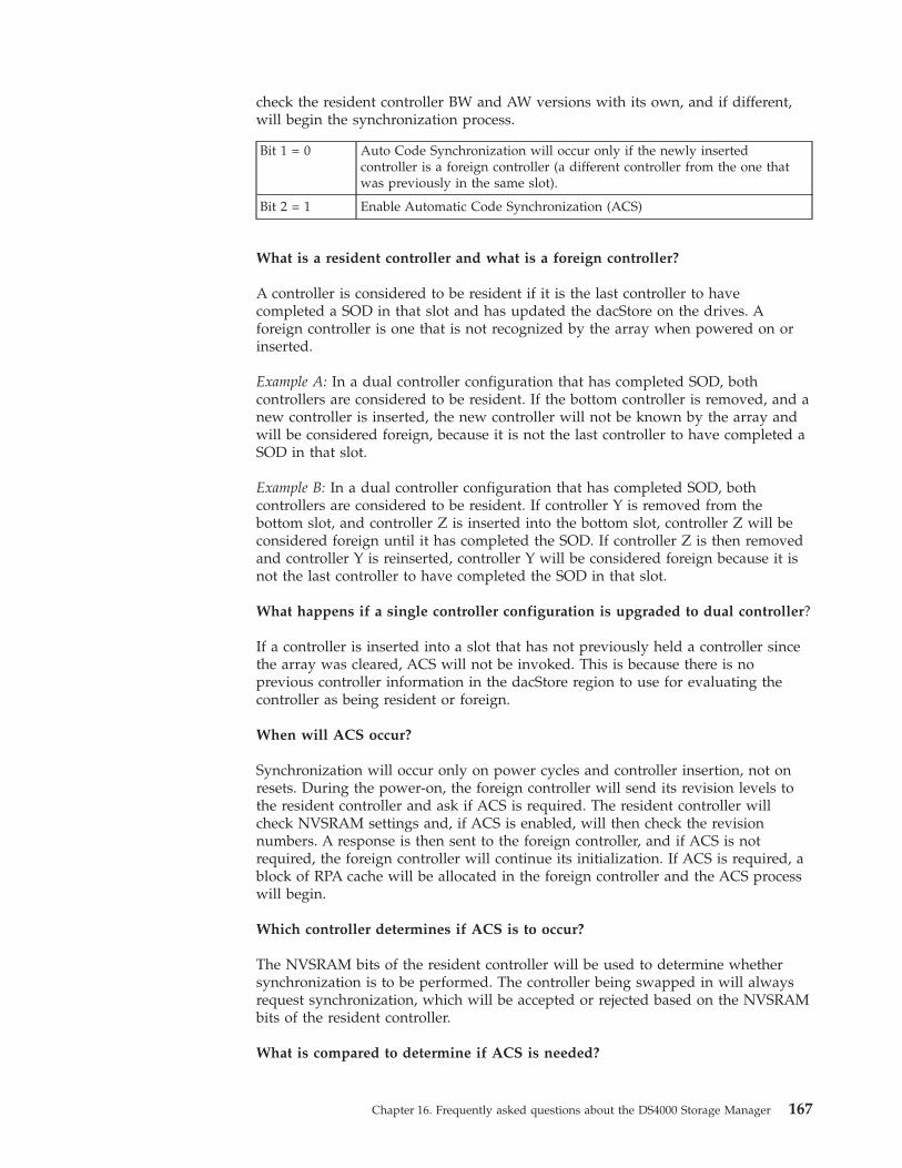
check the resident controller BW and AW versions with its own, and if different,
will begin the synchronization process.
Bit 1 = 0 Auto Code Synchronization will occur only if the newly inserted
controller is a foreign controller (a different controller from the one that
was previously in the same slot).
Bit 2 = 1 Enable Automatic Code Synchronization (ACS)
What is a resident controller and what is a foreign controller?
A controller is considered to be resident if it is the last controller to have
completed a SOD in that slot and has updated the dacStore on the drives. A
foreign controller is one that is not recognized by the array when powered on or
inserted.
Example A: In a dual controller configuration that has completed SOD, both
controllers are considered to be resident. If the bottom controller is removed, and a
new controller is inserted, the new controller will not be known by the array and
will be considered foreign, because it is not the last controller to have completed a
SOD in that slot.
Example B: In a dual controller configuration that has completed SOD, both
controllers are considered to be resident. If controller Y is removed from the
bottom slot, and controller Z is inserted into the bottom slot, controller Z will be
considered foreign until it has completed the SOD. If controller Z is then removed
and controller Y is reinserted, controller Y will be considered foreign because it is
not the last controller to have completed the SOD in that slot.
What happens if a single controller configuration is upgraded to dual controller?
If a controller is inserted into a slot that has not previously held a controller since
the array was cleared, ACS will not be invoked. This is because there is no
previous controller information in the dacStore region to use for evaluating the
controller as being resident or foreign.
When will ACS occur?
Synchronization will occur only on power cycles and controller insertion, not on
resets. During the power-on, the foreign controller will send its revision levels to
the resident controller and ask if ACS is required. The resident controller will
check NVSRAM settings and, if ACS is enabled, will then check the revision
numbers. A response is then sent to the foreign controller, and if ACS is not
required, the foreign controller will continue its initialization. If ACS is required, a
block of RPA cache will be allocated in the foreign controller and the ACS process
will begin.
Which controller determines if ACS is to occur?
The NVSRAM bits of the resident controller will be used to determine whether
synchronization is to be performed. The controller being swapped in will always
request synchronization, which will be accepted or rejected based on the NVSRAM
bits of the resident controller.
What is compared to determine if ACS is needed?
Chapter 16. Frequently asked questions about the DS4000 Storage Manager 167
The entire code revision number will be used for comparison. Both the BW and
AW versions will be compared, and, if either are different, both the BW and AW
will be erased and rewritten. The number of separate loadable partitions is also
compared; if different, the code versions are considered to be different without
considering the revision numbers.
How long will the ACS process take to complete?
The ACS process will begin during the Start-Of-Day process, or between 15 and 30
seconds after power-up or controller insertion. The ACS process for Series 3
controller code will take approximately three minutes to complete. As the code size
increases, the time to synchronize will also increase. Once ACS is complete, do not
remove the controllers for at least three minutes, in case NVSRAM is also
synchronized during the automatic reset.
What will happen if a reset occurs before ACS is complete?
It is important that neither of the controllers are reset during the ACS process. If a
reset occurs during this process, it is likely that the foreign controller will no
longer boot or function correctly, and it might have to be replaced.
Is NVSRAM synchronized by ACS?
NVSRAM synchronization is not part of ACS, but is checked with dacStore on the
drives every time the controller is powered on. The synchronization is not with the
alternate controller, but with the NVSRAM as written to dacStore for the controller
slot. Each controller, slot-A and slot-B, have individual NVSRAM regions within
dacStore. The update process takes approximately five seconds, does not require a
reset, and synchronizes the following NVSRAM regions: UserCfg, NonCfg,
Platform, HostData, SubSys, DrvFault, InfCfg, Array, Hardware, FCCfg, SubSysID,
NetCfg, Board.
Note: No LED display will be seen during the synchronization of the NVSRAM.
What is the order of the synchronization?
Both the BW and AW are synchronized at the same time. NVSRAM will be
checked and synchronized during the automatic reset following the ACS of the
controller code.
Will the controller LEDs flash during ACS?
The function to flash the LEDs during ACS was first enabled in controller
Firmware version 03.01.01.01. If the foreign controller has a release prior to
03.01.01.01, the LED display will not be seen during ACS. The controller being
updated controls the LED synchronization display.
What is the LED display sequence?
If the foreign controller has a Firmware version equal to or newer than 03.01.01.01,
the LEDs will be turned on from right to left, and then turned off left to right. This
sequence will continue until the ACS process is complete.
Is a reset required after ACS is complete?
When the ACS process is complete, the controller will automatically reset.
168 IBM System Storage DS4000: Problem Determination Guide
What is the ACS sequence for controllers with AW prior to 03.01.01.01?
If the foreign controller has AW prior to 03.01.01.01, the LED display will not be
displayed. In this case, the controllers should not be removed or reset for at least
15 minutes. Once the foreign controller has reset, the controller will be ready for
use within two minutes.
Will ACS occur if the controller is cold swapped?
Yes, providing the NVSRAM bits are set to allow ACS to occur.
What happens if both controllers are cold swapped?
If both controllers are cold swapped (that is, if both are foreign), the controller with
the higher FW version number will be loaded onto the alternate controller. This is
simply a numerical comparison. For example, if controller A is 03.01.01.08, and
controller B is 03.01.01.11, then controller A will be upgraded to 03.01.01.11. The
NVSRAM will be updated from dacStore.
What sequence of events should be expected during ACS?
If ACS is enabled, the process will begin about 30 seconds after the controller is
inserted or powered on. When ACS begins, the SYM1000 and the foreign controller
fault lights will begin to flash, and the controller LEDs will begin to turn on one at
a time from right to left, then off left to right. This process will continue for
approximately three minutes until the ACS process is complete. Once the ACS
process is complete, the foreign controller will reset automatically and during the
reset, the NVSRAM will be checked, and updated if needed. The entire process
will take approximately five minutes to complete.
Storage partitioning
Does the Storage Partitions feature alleviate the need to have clustering software
at the host end?
No. Clustering software provides for the movement of applications between hosts
for load balancing and failover. Storage Partitions just provides the ability to
dedicate a portion of the storage to one or more hosts. Storage partitions should
work well with clustering in that a cluster of hosts can be grouped as a Host
Group to provide access to the same storage as needed by the hosts in that cluster.
If I have two hosts in a host group sharing the same logical drives, and both
hosts trying to modify the same data on the same logical drive, how are conflicts
resolved?
This is one of the primary value adds of clustering software. Clustering software
comes in two flavors:
v Shared Nothing - In this model, clustered hosts partition the storage between the
hosts in the cluster. In this model, only one host at a time obtains access to a
particular set of data. In the event load balancing or a server failure dictates, the
cluster software manages a data ownership transition of the set of data to
another host. Microsoft MSCS is an example.
Chapter 16. Frequently asked questions about the DS4000 Storage Manager 169
v Shared Clustering - In this model, clustered hosts all access the same data
concurrently. The cluster software provides management of locks between hosts
that prevents two hosts from accessing the same data at the same time. Sun
Cluster Server is an example.
Note: In the DS4000 Storage Manager version 7 client, you cannot change the
default host type until the Write Storage Partitioning feature is disabled.
How many partitions does the user really get?
By default, the user has one partition always associated with the default host
group. Therefore, when the user enables additional partitions, up to 8 for example,
they are technically getting eight partitions in addition to the ″default″ partition.
When you enable additional partitions, move any logical drives that are in the
default host group into the new partition.
Why should I not use the default host group’s partition?
You can potentially run into logical drive/LUN collisions if you replace a host port
in a host without using the tools in the Definitions window to associate the new
host port with the host.
Furthermore, there is no read/write access control on logical drives that are located
in the same partition. For Microsoft Windows operating systems, data corruption
occurs if a logical drive is mounted on more than two systems without the
presence of middleware, such as Cluster Service, to provide read/write access
locking.
Example: You have Host 1 mapped to logical drive Fred using LUN 1. There is
also a logical drive George, which is still part of the Default Host Group that uses
LUN 1. If you replace a host adapter in Host 1 without associating the new host
adapter with Host 1, then Host 1 will now have access to logical drive George,
instead of logical drive Fred, through LUN 1. Data corruption can occur.
Miscellaneous
What is the best way to identify which NVSRAM file version has been installed
on the system when running in the controller?
In the DS4000 Storage Manager, use the profile command. The NVSRAM version is
included in the board/controller area.
Alternatively, in the ″subsystem management″ window, right-click the storage
subsystem and select Download -> NVSRAM. The NVSRAM version is displayed.
When using arrayPrintSummary in the controller shell, what does synchronized
really mean and how is it determined?
The term synchronized in the shell has nothing to do with firmware or NVSRAM.
Simply put, synchronized usually means the controllers have successfully completed
SOD in an orderly manner and have synchronized cache. A semaphore is passed
back and forth between the controllers as one or more of the controllers are going
through SOD. If this semaphore gets stuck on one controller, or if a controller does
not make it through SOD, the controllers will not come up synchronized.
170 IBM System Storage DS4000: Problem Determination Guide
One way the semaphore can get stuck is if a LUN or its cache cannot be
configured. In addition, if a controller has a memory parity error, the controllers
will not be synchronized. There have been cases where one controller states the
controllers are synchronized while its alternate states that they are not. One cause
of this is that a LUN might be ’locked’ by the non-owning controller; this can
sometimes be fixed by turning off bit 3 of byte 0x29 in NVSRAM (Reserve and
Release).
The DS4000 Storage Manager shows the nodes in the ″enterprise″ window with
either IP address or machine name. Why is this not consistent?
The DS4000 Storage Manager tries to associate a name with each host node, but if
one is not found, then the IP address is used. The inconsistency occurs because the
client software cannot resolve the IP address to a name, or the user has manually
added a host node by IP address.
Why do you see shared fibre drives twice during text setup of NT/W2K? The
UTM does not seem protected (because you can create/delete the partition).
The UTM is only necessary if the Agent software is installed on a host. If you are
direct-attached (network-attached) to a module, you do not need the Agent. This,
in turn, means you do not need the UTM LUN. RDAC is what ’hides’ the UTM
from the host and creates the failover nodes. If RDAC is not installed on an
operating system, then the UTM will appear to be a normal disk (either 20 Mbytes
or 0 MBytes) to the operating system. However, there is no corresponding data
space ″behind″ the UTM; the controller code write-protects this region. The
controller will return an error if an attempt is made to write to this nonexistent
data region. The error is an ASC/ASCQ of 21/00 - Logical block address out of
range, in the Event Viewer.
For Linux operating systems, the UTM LUN is not required and should not be
present for a Linux Host.
If RDAC is not installed on a host, and NVSRAM offset 0x24 is set to 0, then you
will see each LUN twice (once per controller). This is necessary because most
HBAs need to see a LUN 0 on a controller in order for the host to come up. You
should only be able to format one of the listed devices by using the node name
which points to the controller that really owns the disk. You will probably get an
error if you try to format a LUN through the node pointing to the non-owning
controller. The UTM is ″owned″ by both controllers as far as the controller code is
concerned, so you will probably be able to format or partition the UTM on either
node.
In short, if RDAC is not installed, the UTM will appear to be a regular disk to the
host. Also, you will see each disk twice. In this case, it is up to the user to know
not to partition the UTM, and to know which of the two nodes for each device is
the true device.
How can you determine from the MEL, which node has caused problems (that
is, which node failed the controller)?
You cannot tell which host failed a controller in a multi-host environment. You
need to use the host Event Log to determine which host is having problems.
Chapter 16. Frequently asked questions about the DS4000 Storage Manager 171
When RDAC initiates a Path failure and sets a controller to passive, why does
the status in the ″enterprise″ window of the DS4000 Storage Manager shows the
subsystem as optimal?
This is a change in the design from older code which should prove to be a useful
support tool once we get used to it. A ’failed’ controller which shows as passive in
the EMW window, but which has been failed by RDAC, indicates that no hardware
problem could be found on the controller. This type of state implies that we have a
problem in the path to the controller, not with the controller itself. In short, a bad
cable, hub, GBIC, and so on, on the host side is probably why the failover
occurred. Hopefully, this will minimize the number of controllers which are
mistakenly returned as bad.
(NT/W2K) What is the equivalent for symarray (NT) with the DS4000 Storage
Manager W2K?
rdacfltr is the ″equivalent″ of symarray. However, symarray was a class driver,
whereas rdacfltr is a Low level filter driver. rdacfltr will report Event 3
(configuration changes) and Event 18 (failover events) information. Any errors
which are not of this type (such as check conditions) will be reported by W2K’s
class driver. These errors will be logged by the (disk) class driver. ASC/ASCQ
codes and SRB status information should appear in the same location in these
errors. The major difference is this break up of errors in W2K, but the error
information should be available under one of these two sources in the Event Log.
172 IBM System Storage DS4000: Problem Determination Guide

Chapter 17. pSeries supplemental problem determination
information
If a problem occurs in the fibre channel environment, you will need a number of
pieces of information to successfully correct the problem. This chapter discusses
fibre channel environment-specific problems on IBM pSeries servers as well as
6227, 6228, 6239, and 5716 HBAs. If you experience problems with the AIX system,
see your AIX documentation.
For detailed information about installation and configuration, see the installation
and users guide that is specific to your fibre channel environment at:
www-03.ibm.com/servers/storage/support/disk
Nature of fibre channel environment problems
In the complex and diverse fibre channel environment, a wide variety of problems
can be encountered. These problems might include, but are not limited to the
following list:
v A Gigabit Fibre Channel PCI Adapter in an AIX system has a hardware defect.
v The device driver for a Gigabit Fibre Channel PCI Adapter in an AIX system has
a hardware defect.
v The device driver for a Gigabit Fibre Channel PCI Adapter has been incorrectly
installed or is exhibiting incorrect behavior.
v A port in a fibre channel switch is defective, incorrectly zoned, or blocked.
v Ports in a fibre channel switch have been rezoned and the cfgmgr command has
not been run to set up the new configuration parameters.
v A fibre channel adapter has been replaced and zoning or DS4000 storage
partitioning has not been updated.
v A port adapter in a Disk Storage Subsystem has a hardware defect.
v A fibre channel cable connector is not properly seated, dirty, or defective.
As can be seen in the above list, problems can be encountered anywhere
throughout the fibre channel configuration. Sometimes the problem is distinctly
reported by, and at the failing component. Often, however, the AIX system host, as
the initiator, detects and reports the error condition. As a result, fibre channel
errors reported by the AIX system must be analyzed carefully to determine the
true origin of the failure.
Note: Do not pursue problem determination by Field Replaceable Unit (FRU)
replacement in the AIX system unless the problem is isolated to this host
component.
Requirements before starting problem determination
The following system administrators might be needed to perform the problem
determination procedures:
v AIX system administrator
v DS4000 disk subsystem administrator
v Fiber Channel switch administrator
© Copyright IBM Corp. 2006 173

Note: If the host is connected directly to the Storage Subsystem, a Fiber Channel
switch administrator is not needed.
Verify that all the AIX fiber channel drivers and adapter firmware are at the
minimum requirements, or a higher level, by checking the DS4000 Storage
Manager readme file for your operating system. To download the readme file,
complete the following steps:
1. Access the following Web site:
www-03.ibm.com/servers/storage/support/disk
2. Click the link for your storage subsystem.
3. When the subsystem page opens, click the Download tab.
4. When the download page opens, click the link for Storage Manager.
5. When the next page opens, click the Storage Mgr tab. A table displays.
6. In the table, find the entry for IBM DS4000 Storage Manager for AIX, and click
corresponding link under the Current Versions and Readmes column.
Fibre channel environment problem determination procedures
This section provides basic problem-determination procedures for the fibre-channel
environment. These procedures are intended to help isolate problems. Because of
the complexity of the environment, a single fibre-channel problem can result in a
large volume of error reports in the AIX system. Carefully analyze these logged
errors to find the error that represents the original root cause. In addition, while
fibre-channel-environment problems are often reported by the AIX system,
indiscriminate replacement of the Gigabit Fibre Channel PCI Adapter is not the
recommended problem-determination procedure.
For detailed installation and configuration information, see the installation and users
guide for your fibre-channel environment.
http://www.ibm.com/servers/storage/support/disk/
Note: It is important that you clearly understand the topology of your
configuration.
174 IBM System Storage DS4000: Problem Determination Guide
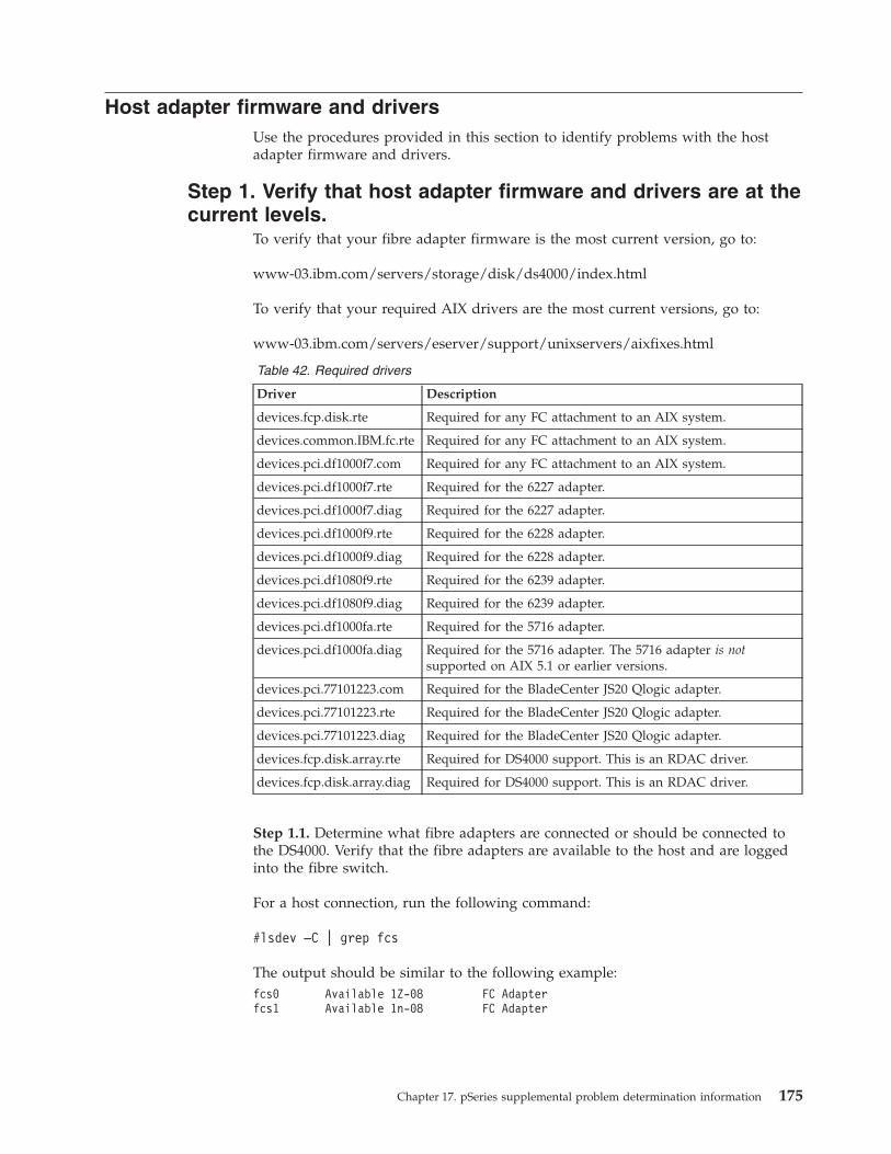
Host adapter firmware and drivers
Use the procedures provided in this section to identify problems with the host
adapter firmware and drivers.
Step 1. Verify that host adapter firmware and drivers are at the
current levels.
To verify that your fibre adapter firmware is the most current version, go to:
www-03.ibm.com/servers/storage/disk/ds4000/index.html
To verify that your required AIX drivers are the most current versions, go to:
www-03.ibm.com/servers/eserver/support/unixservers/aixfixes.html
Table 42. Required drivers
Driver Description
devices.fcp.disk.rte Required for any FC attachment to an AIX system.
devices.common.IBM.fc.rte Required for any FC attachment to an AIX system.
devices.pci.df1000f7.com Required for any FC attachment to an AIX system.
devices.pci.df1000f7.rte Required for the 6227 adapter.
devices.pci.df1000f7.diag Required for the 6227 adapter.
devices.pci.df1000f9.rte Required for the 6228 adapter.
devices.pci.df1000f9.diag Required for the 6228 adapter.
devices.pci.df1080f9.rte Required for the 6239 adapter.
devices.pci.df1080f9.diag Required for the 6239 adapter.
devices.pci.df1000fa.rte Required for the 5716 adapter.
devices.pci.df1000fa.diag Required for the 5716 adapter. The 5716 adapter is not
supported on AIX 5.1 or earlier versions.
devices.pci.77101223.com Required for the BladeCenter JS20 Qlogic adapter.
devices.pci.77101223.rte Required for the BladeCenter JS20 Qlogic adapter.
devices.pci.77101223.diag Required for the BladeCenter JS20 Qlogic adapter.
devices.fcp.disk.array.rte Required for DS4000 support. This is an RDAC driver.
devices.fcp.disk.array.diag Required for DS4000 support. This is an RDAC driver.
Step 1.1. Determine what fibre adapters are connected or should be connected to
the DS4000. Verify that the fibre adapters are available to the host and are logged
into the fibre switch.
For a host connection, run the following command:
#lsdev –C | grep fcs
The output should be similar to the following example:
fcs0 Available 1Z-08 FC Adapter
fcs1 Available 1n-08 FC Adapter
Chapter 17. pSeries supplemental problem determination information 175
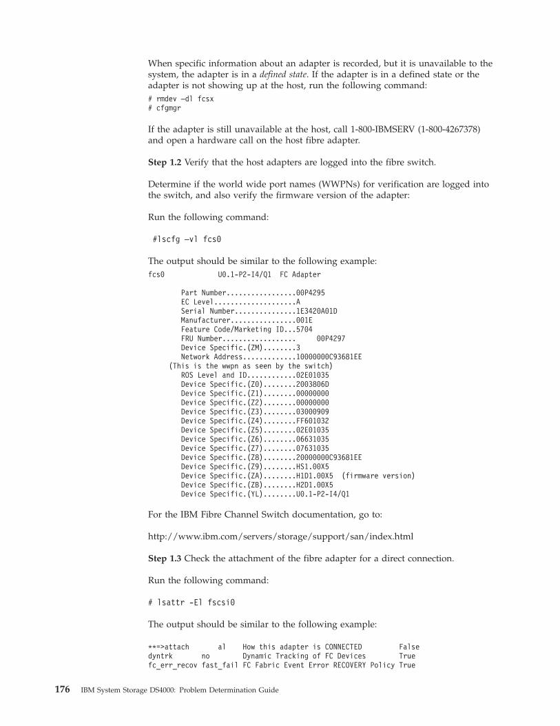
When specific information about an adapter is recorded, but it is unavailable to the
system, the adapter is in a defined state. If the adapter is in a defined state or the
adapter is not showing up at the host, run the following command:
# rmdev –dl fcsx
# cfgmgr
If the adapter is still unavailable at the host, call 1-800-IBMSERV (1-800-4267378)
and open a hardware call on the host fibre adapter.
Step 1.2 Verify that the host adapters are logged into the fibre switch.
Determine if the world wide port names (WWPNs) for verification are logged into
the switch, and also verify the firmware version of the adapter:
Run the following command:
#lscfg –vl fcs0
The output should be similar to the following example:
fcs0 U0.1-P2-I4/Q1 FC Adapter
Part Number.................00P4295
EC Level....................A
Serial Number...............1E3420A01D
Manufacturer................001E
Feature Code/Marketing ID...5704
FRU Number.................. 00P4297
Device Specific.(ZM)........3
Network Address.............10000000C93681EE
(This is the wwpn as seen by the switch)
ROS Level and ID............02E01035
Device Specific.(Z0)........2003806D
Device Specific.(Z1)........00000000
Device Specific.(Z2)........00000000
Device Specific.(Z3)........03000909
Device Specific.(Z4)........FF601032
Device Specific.(Z5)........02E01035
Device Specific.(Z6)........06631035
Device Specific.(Z7)........07631035
Device Specific.(Z8)........20000000C93681EE
Device Specific.(Z9)........HS1.00X5
Device Specific.(ZA)........H1D1.00X5 (firmware version)
Device Specific.(ZB)........H2D1.00X5
Device Specific.(YL)........U0.1-P2-I4/Q1
For the IBM Fibre Channel Switch documentation, go to:
http://www.ibm.com/servers/storage/support/san/index.html
Step 1.3 Check the attachment of the fibre adapter for a direct connection.
Run the following command:
# lsattr -El fscsi0
The output should be similar to the following example:
**=>attach al How this adapter is CONNECTED False
dyntrk no Dynamic Tracking of FC Devices True
fc_err_recov fast_fail FC Fabric Event Error RECOVERY Policy True
176 IBM System Storage DS4000: Problem Determination Guide
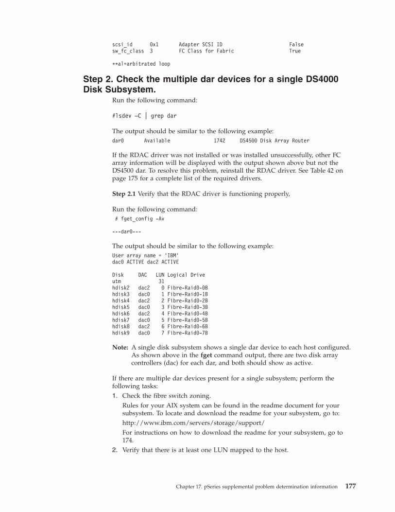
scsi_id 0x1 Adapter SCSI ID False
sw_fc_class 3 FC Class for Fabric True
**al=arbitrated loop
Step 2. Check the multiple dar devices for a single DS4000
Disk Subsystem.
Run the following command:
#lsdev –C | grep dar
The output should be similar to the following example:
dar0 Available 1742 DS4500 Disk Array Router
If the RDAC driver was not installed or was installed unsuccessfully, other FC
array information will be displayed with the output shown above but not the
DS4500 dar. To resolve this problem, reinstall the RDAC driver. See Table 42 on
page 175 for a complete list of the required drivers.
Step 2.1 Verify that the RDAC driver is functioning properly,
Run the following command:
# fget_config -Av
---dar0---
The output should be similar to the following example:
User array name = ’IBM’
dac0 ACTIVE dac2 ACTIVE
Disk DAC LUN Logical Drive
utm 31
hdisk2 dac2 0 Fibre-Raid0-0B
hdisk3 dac0 1 Fibre-Raid0-1B
hdisk4 dac2 2 Fibre-Raid0-2B
hdisk5 dac0 3 Fibre-Raid0-3B
hdisk6 dac2 4 Fibre-Raid0-4B
hdisk7 dac0 5 Fibre-Raid0-5B
hdisk8 dac2 6 Fibre-Raid0-6B
hdisk9 dac0 7 Fibre-Raid0-7B
Note: A single disk subsystem shows a single dar device to each host configured.
As shown above in the fget command output, there are two disk array
controllers (dac) for each dar, and both should show as active.
If there are multiple dar devices present for a single subsystem; perform the
following tasks:
1. Check the fibre switch zoning.
Rules for your AIX system can be found in the readme document for your
subsystem. To locate and download the readme for your subsystem, go to:
http://www.ibm.com/servers/storage/support/
For instructions on how to download the readme for your subsystem, go to
174.
2. Verify that there is at least one LUN mapped to the host.
Chapter 17. pSeries supplemental problem determination information 177

Use the SMclient Mappings view to review the LUN mapping, and verify that
the WWPN’s for the host adapters are configured correctly in the DS4000
Storage Manager.
To open the SMclient Mappings view, perform the following steps:
a. Perform one of the following steps:
v Right click one of the host ports, and then click Show All Host Port
Information.
v Select the Storage Subsystem menu from the toolbar, and then click View
-> Profile. A new window opens.b. Click the Mappings tab, and then scroll down to TOPOLOGY
DEFINITIONS. All the hosts and adapter worldwide port names are
displayed.
After the problem has been identified and resolved, run the following commands:
# rmdev –dl darX –R (run this command for each dar device)
# rmdev –dl dacX (run this command for each dac device)
# rmdev –dl fcsX –R (run this command for each fcs device)
# cfgmgr
Step 3. Check whether the dar is showing as dacNONE.
You should not see any dacNONE array controllers.
Step 3.1 Verify that the WWPNs for both controllers are logged in the Fibre
Channel switch.
If a fibre adapter in the host or the DS4000 is not logged in the switch, there might
be a physical cabling problem, defective fiber cable, or defective fiber component
within the adapter. To see the Switch documentation, go to:
http://www.ibm.com/servers/storage/support/san/index.html
Using the Storage Manager Client, the WWPN’s for the controllers can viewed in
the Storage Subsystem Profile.
1. Select the Storage Subsystem menu from the toolbar.
2. Click View -> Profile. A new window opens.
3. Click the Controllers tab, and then scroll down to view the WWPN’s for each
controller port.
If the dac device is available to the host, use the following command to verify the
WWPNs:
#lsattr –EL dac0
The output should be similar to the following example:
passive_control no Passive controller False
alt_held_reset no Alternate held in reset False
controller_SN 1T44566835 Controller serial number False
ctrl_type 1815 Controller Type False
cache_size 2048 Cache Size in MBytes False
scsi_id 0x10400 SCSI ID False
lun_id 0x0 Logical Unit Number False
utm_lun_id 0x001f000000000000 Logical Unit Number False
location Location Label True
178 IBM System Storage DS4000: Problem Determination Guide

ww_name 0x202400a0b8111252 World Wide Name False (WWPN)
node_name 0x200400a0b8111252 FC Node Name False
GLM_type low GLM type False
Step 3.2 Determine the host adapter world wide port name.
Run the following command:
Lscfg –vl fcsx
Note: The x represents the number of the fcs device. See the output example in
175
Step 3.3 Verify that the RDAC driver is functioning properly.
Run the following command:
# fget_config -Av ---dar0
The output should look similar to the following example:
User array name = ’IBM’
dac0 ACTIVE dac2 ACTIVE
Disk DAC LUN Logical Drive
utm 31
hdisk2 dac2 0 Fibre-Raid0-0B
hdisk3 dac0 1 Fibre-Raid0-1B
hdisk4 dac2 2 Fibre-Raid0-2B
hdisk5 dac0 3 Fibre-Raid0-3B
hdisk6 dac2 4 Fibre-Raid0-4B
hdisk7 dac0 5 Fibre-Raid0-5B
hdisk8 dac2 6 Fibre-Raid0-6B
hdisk9 dac0 7 Fibre-Raid0-7B
A single disk subsystem should show a single disk array router (dar) device to
each host configured. As seen in the preceding fget command output, there should
be two dac devices for each dar device, and both should be seen as active. A single
disk subsystem shows a single dar device to each host configured. As seen in the
preceding fget command output, there are two dac devices for each dar, and both
should show as active.
After the problem has been identified and resolved, run the following commands:
rmdev –dl darx –R for all dar devices.
rmdev –dl dacx for all dac devices.
rmdev –dl fcsx –R for all fcs devices
cfgmgr
Step 4. Verify that the hdisks are showing up correctly with
the fget_config –Av command and the lsdev –Cc disk
command, or both.
Use the SMclient to verify that the created LUNs are mapped to this host. Select
the Mappings View tab next to the Logical/Physical View tab. On the right side of
the window, verify that the Logical Drive Name is displayed and that the
Accessible By column lists the correct host. If the mappings are not displayed, then
map the previously created LUNs. In the Mappings view (in the upper left side of
Chapter 17. pSeries supplemental problem determination information 179

the window), you will see undefined mappings. Right click an undefined mapping,
and then select define additional mapping, run the cfgmgr command on the host
to display the newly mapped LUNs.
If the LUNs do not display or are displayed but are inaccessible by the host, there
might be some type of reservation on the LUN. You can locate, and then clear
Persistent Reservations from the SMclient, if you are certain that the LUN is not in
use by another host. Use extreme caution in clearing reservations when the LUN is
configured to be seen by the Host Group. Select Maintenance -> Persistent
Reservation from the toolbar, and then select the Advanced tab.
Step 5. Verify that the fget_config –Av command displays all
the correct (expected) output from the DS4000.
Make sure that all the information shown below is correct.
v All drivers and firmware are installed and current.
v The DS4000 controllers and host adapters are logged in the switches and are
zoned correctly.
v The Switch firmware is the current (near the latest) or latest available version.
v The zoning is verified and correct.
For more information, go to the following IBM Web site:
http://www.ibm.com/servers/storage/support/san/index.html
v The host world wide port names are configured correctly in the SMclient.
v The DS4000 firmware is current (latest version).
v All AIX errors are being logged in the AIX errpt (error log) file.
Note: Call 1-800-IBM-SERV (1-800-IBM-7378) to open a service call with IBM
Hardware Support to analyze the AIX error logs.
v All event errors are being logged in the SMclient Major Event Log. Open a
service call with hardware support to analyze the event log 1-800-IBM-SERV
Note: Call 1-800-IBM-SERV (1-800-IBM-7378) to open a service call with IBM
Hardware Support to analyze the event log.
180 IBM System Storage DS4000: Problem Determination Guide

Appendix A. Additional DS4000 documentation
The following tables present an overview of the IBM System Storage DS4000
Storage Manager, Storage Subsystem, and Storage Expansion Enclosure product
libraries, as well as other related documents. Each table lists documents that are
included in the libraries and what common tasks they address.
You can access the documents listed in these tables at both of the following Web
sites:
www.ibm.com/servers/storage/support/disk/
www.ibm.com/shop/publications/order/
DS4000 Storage Manager Version 9 library
Table 43 associates each document in the DS4000 Storage Manager Version 9 library
with its related common user tasks.
Table 43. DS4000 Storage Manager Version 9.1 titles by user tasks
Title User tasks
Planning Hardware
installation
Software
installation
Configuration Operation and
administration
Diagnosis and
maintenance
IBM System Storage
DS4000 Storage
Manager Version 9
Installation and
Support Guide for
Windows 2000/Server
2003, NetWare, ESX
Server, and Linux
U U U
IBM System Storage
DS4000 Storage
Manager Version 9
Installation and
Support Guide for
AIX, UNIX®, Solaris
and Linux on
POWER™
U U U
IBM System Storage
DS4000 Storage
Manager Version 9
Copy Services User’s
Guide
U U U U
IBM TotalStorage®
DS4000 Storage
Manager Version 9
Concepts Guide
U U U U U U
© Copyright IBM Corp. 2006 181
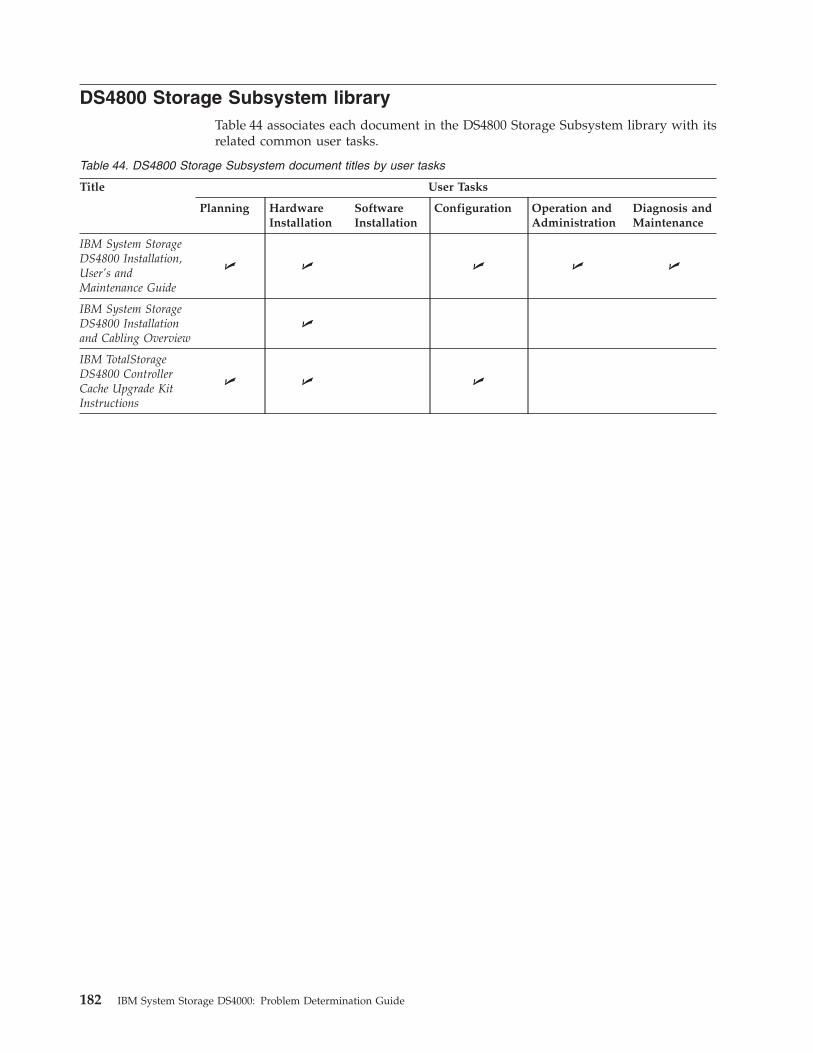
DS4800 Storage Subsystem library
Table 44 associates each document in the DS4800 Storage Subsystem library with its
related common user tasks.
Table 44. DS4800 Storage Subsystem document titles by user tasks
Title User Tasks
Planning Hardware
Installation
Software
Installation
Configuration Operation and
Administration
Diagnosis and
Maintenance
IBM System Storage
DS4800 Installation,
User’s and
Maintenance Guide
U U U U U
IBM System Storage
DS4800 Installation
and Cabling Overview
U
IBM TotalStorage
DS4800 Controller
Cache Upgrade Kit
Instructions
U U U
182 IBM System Storage DS4000: Problem Determination Guide

DS4700 Storage Subsystem library
Table 45 associates each document in the DS4700 Storage Subsystem library with its
related common user tasks.
Table 45. DS4700 Storage Subsystem document titles by user tasks
Title User Tasks
Planning Hardware
Installation
Software
Installation
Configuration Operation and
Administration
Diagnosis and
Maintenance
IBM System Storage
DS4700 Installation,
User’s and
Maintenance Guide
U U U U U
IBM System Storage
DS4700 Storage
Subsystem Fibre
Channel Cabling
Guide
U
Appendix A. Additional DS4000 documentation 183
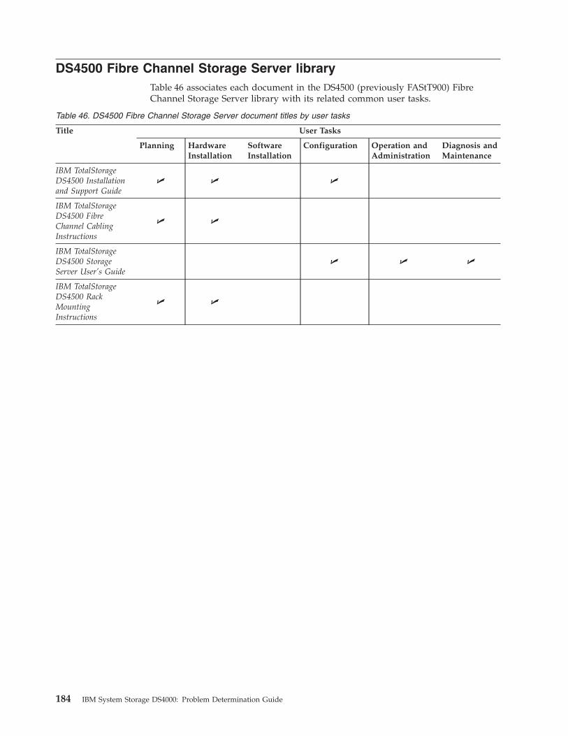
DS4500 Fibre Channel Storage Server library
Table 46 associates each document in the DS4500 (previously FAStT900) Fibre
Channel Storage Server library with its related common user tasks.
Table 46. DS4500 Fibre Channel Storage Server document titles by user tasks
Title User Tasks
Planning Hardware
Installation
Software
Installation
Configuration Operation and
Administration
Diagnosis and
Maintenance
IBM TotalStorage
DS4500 Installation
and Support Guide
U U U
IBM TotalStorage
DS4500 Fibre
Channel Cabling
Instructions
U U
IBM TotalStorage
DS4500 Storage
Server User’s Guide
U U U
IBM TotalStorage
DS4500 Rack
Mounting
Instructions
U U
184 IBM System Storage DS4000: Problem Determination Guide
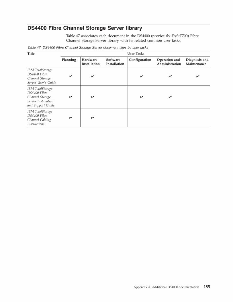
DS4400 Fibre Channel Storage Server library
Table 47 associates each document in the DS4400 (previously FAStT700) Fibre
Channel Storage Server library with its related common user tasks.
Table 47. DS4400 Fibre Channel Storage Server document titles by user tasks
Title User Tasks
Planning Hardware
Installation
Software
Installation
Configuration Operation and
Administration
Diagnosis and
Maintenance
IBM TotalStorage
DS4400 Fibre
Channel Storage
Server User’s Guide
U U U U U
IBM TotalStorage
DS4400 Fibre
Channel Storage
Server Installation
and Support Guide
U U U U
IBM TotalStorage
DS4400 Fibre
Channel Cabling
Instructions
U U
Appendix A. Additional DS4000 documentation 185

DS4300 Fibre Channel Storage Server library
Table 48 associates each document in the DS4300 (previously FAStT600) Fibre
Channel Storage Server library with its related common user tasks.
Table 48. DS4300 Fibre Channel Storage Server document titles by user tasks
Title User Tasks
Planning Hardware
Installation
Software
Installation
Configuration Operation and
Administration
Diagnosis and
Maintenance
IBM TotalStorage
DS4300 Fibre
Channel Storage
Server Installation
and User’s Guide
U U U
IBM TotalStorage
DS4300 Rack
Mounting
Instructions
U U
IBM TotalStorage
DS4300 Fibre
Channel Cabling
Instructions
U U
IBM TotalStorage
DS4300 SCU Base
Upgrade Kit
U U
IBM TotalStorage
DS4300 SCU Turbo
Upgrade Kit
U U
IBM TotalStorage
DS4300 Turbo Models
6LU/6LX Upgrade Kit
U U
186 IBM System Storage DS4000: Problem Determination Guide
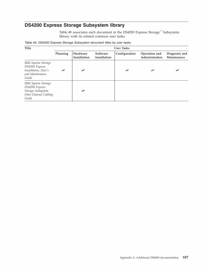
DS4200 Express Storage Subsystem library
Table 49 associates each document in the DS4200 Express Storage™ Subsystem
library with its related common user tasks.
Table 49. DS4200 Express Storage Subsystem document titles by user tasks
Title User Tasks
Planning Hardware
Installation
Software
Installation
Configuration Operation and
Administration
Diagnosis and
Maintenance
IBM System Storage
DS4200 Express
Installation, User’s
and Maintenance
Guide
U U U U U
IBM System Storage
DS4200 Express
Storage Subsystem
Fibre Channel Cabling
Guide
U
Appendix A. Additional DS4000 documentation 187

DS4100 SATA Storage Server library
Table 50 associates each document in the DS4100 (previously FAStT100) SATA
Storage Server library with its related common user tasks.
Table 50. DS4100 SATA Storage Server document titles by user tasks
Title User Tasks
Planning Hardware
Installation
Software
Installation
Configuration Operation and
Administration
Diagnosis and
Maintenance
IBM TotalStorage
DS4100 Installation,
User’s and
Maintenance Guide
U U U U U
IBM TotalStorage
DS4100 Cabling
Guide
U
188 IBM System Storage DS4000: Problem Determination Guide

DS4000 Storage Expansion Enclosure documents
Table 51 associates each of the following documents with its related common user
tasks.
Table 51. DS4000 Storage Expansion Enclosure document titles by user tasks
Title User Tasks
Planning Hardware
Installation
Software
Installation
Configuration Operation and
Administration
Diagnosis and
Maintenance
IBM System Storage
DS4000 EXP810
Storage Expansion
Enclosures
Installation, User’s,
and Maintenance
Guide
U U U U U
IBM TotalStorage
DS4000 EXP700 and
EXP710 Storage
Expansion Enclosures
Installation, User’s,
and Maintenance
Guide
U U U U U
Fibre Channel
Solutions - IBM
DS4000 EXP500
Installation and
User’s Guide
U U U U U
IBM System Storage
DS4000 EXP420
Storage Expansion
Enclosures
Installation, User’s,
and Maintenance
Guide
U U U U U
IBM System Storage
DS4000 Hard Drive
and Storage
Expansion Enclosures
Installation and
Migration Guide
U U
Appendix A. Additional DS4000 documentation 189
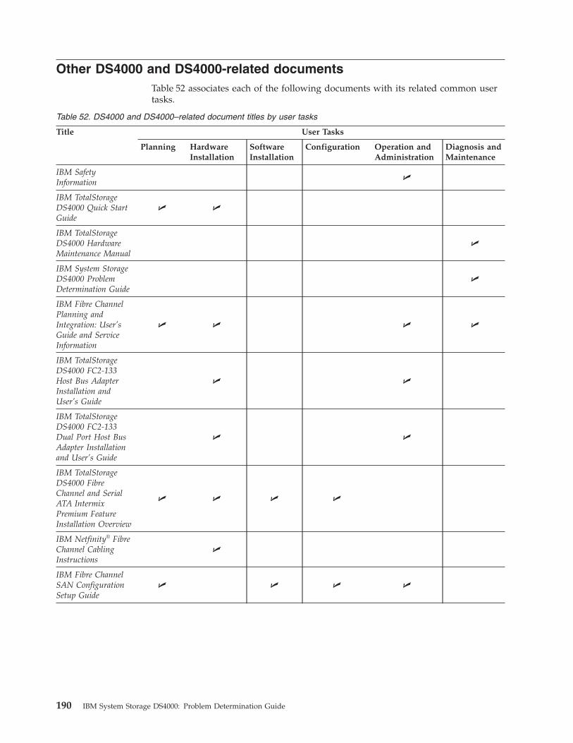
Other DS4000 and DS4000-related documents
Table 52 associates each of the following documents with its related common user
tasks.
Table 52. DS4000 and DS4000–related document titles by user tasks
Title User Tasks
Planning Hardware
Installation
Software
Installation
Configuration Operation and
Administration
Diagnosis and
Maintenance
IBM Safety
Information
U
IBM TotalStorage
DS4000 Quick Start
Guide
U U
IBM TotalStorage
DS4000 Hardware
Maintenance Manual
U
IBM System Storage
DS4000 Problem
Determination Guide
U
IBM Fibre Channel
Planning and
Integration: User’s
Guide and Service
Information
U U U U
IBM TotalStorage
DS4000 FC2-133
Host Bus Adapter
Installation and
User’s Guide
U U
IBM TotalStorage
DS4000 FC2-133
Dual Port Host Bus
Adapter Installation
and User’s Guide
U U
IBM TotalStorage
DS4000 Fibre
Channel and Serial
ATA Intermix
Premium Feature
Installation Overview
U U U U
IBM Netfinity® Fibre
Channel Cabling
Instructions
U
IBM Fibre Channel
SAN Configuration
Setup Guide
U U U U
190 IBM System Storage DS4000: Problem Determination Guide

Appendix B. Accessibility
This section provides information about alternate keyboard navigation, which is a
DS4000 Storage Manager accessibility feature. Accessibility features help a user
who has a physical disability, such as restricted mobility or limited vision, to use
software products successfully.
By using the alternate keyboard operations that are described in this section, you
can use keys or key combinations to perform Storage Manager tasks and initiate
many menu actions that can also be done with a mouse.
Note: In addition to the keyboard operations that are described in this section, the
DS4000 Storage Manager 9.14, 9.15, and 9.16 software installation packages for
Windows include a screen reader software interface. To enable the screen reader,
select Custom Installation when using the installation wizard to install Storage
Manager 9.14, 9.15, or 9.16 on a Windows host/management station. Then, in the
Select Product Features window, select Java Access Bridge in addition to the other
required host software components.
Table 53 defines the keyboard operations that enable you to navigate, select, or
activate user interface components. The following terms are used in the table:
v Navigate means to move the input focus from one user interface component to
another.
v Select means to choose one or more components, typically for a subsequent
action.
v Activate means to carry out the action of a particular component.
Note: In general, navigation between components requires the following keys:
v Tab - Moves keyboard focus to the next component or to the first member
of the next group of components
v Shift-Tab - Moves keyboard focus to the previous component or to the
first component in the previous group of components
v Arrow keys - Move keyboard focus within the individual components of
a group of components
Table 53. DS4000 Storage Manager alternate keyboard operations
Short cut Action
F1 Open the Help.
F10 Move keyboard focus to main menu bar and post first
menu; use the arrow keys to navigate through the
available options.
Alt+F4 Close the management window.
Alt+F6 Move keyboard focus between dialogs (non-modal) and
between management windows.
© Copyright IBM Corp. 2006 191
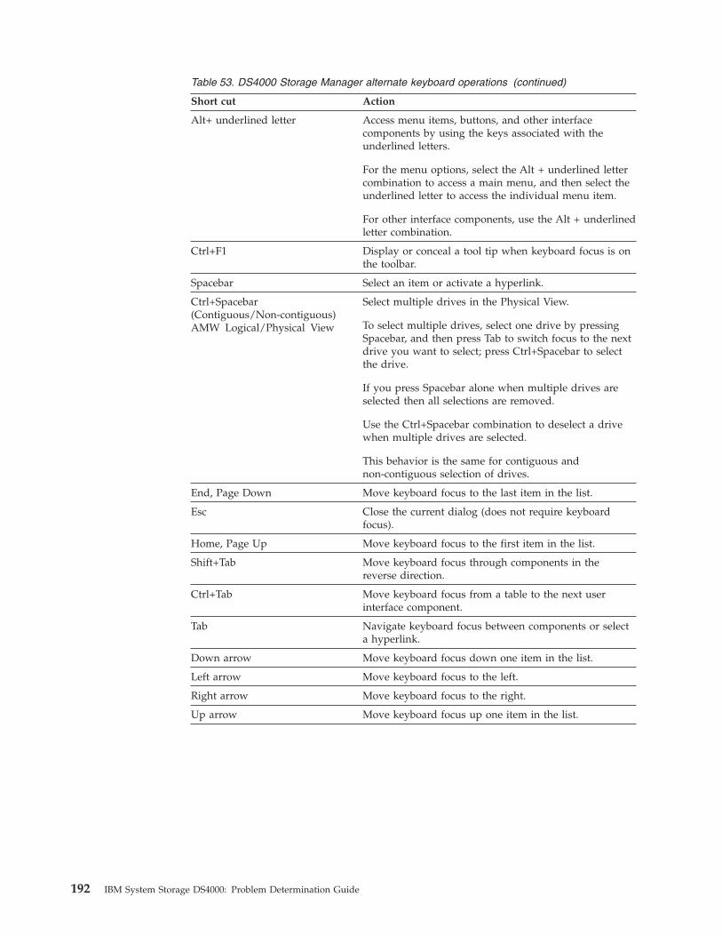
Table 53. DS4000 Storage Manager alternate keyboard operations (continued)
Short cut Action
Alt+ underlined letter Access menu items, buttons, and other interface
components by using the keys associated with the
underlined letters.
For the menu options, select the Alt + underlined letter
combination to access a main menu, and then select the
underlined letter to access the individual menu item.
For other interface components, use the Alt + underlined
letter combination.
Ctrl+F1 Display or conceal a tool tip when keyboard focus is on
the toolbar.
Spacebar Select an item or activate a hyperlink.
Ctrl+Spacebar
(Contiguous/Non-contiguous)
AMW Logical/Physical View
Select multiple drives in the Physical View.
To select multiple drives, select one drive by pressing
Spacebar, and then press Tab to switch focus to the next
drive you want to select; press Ctrl+Spacebar to select
the drive.
If you press Spacebar alone when multiple drives are
selected then all selections are removed.
Use the Ctrl+Spacebar combination to deselect a drive
when multiple drives are selected.
This behavior is the same for contiguous and
non-contiguous selection of drives.
End, Page Down Move keyboard focus to the last item in the list.
Esc Close the current dialog (does not require keyboard
focus).
Home, Page Up Move keyboard focus to the first item in the list.
Shift+Tab Move keyboard focus through components in the
reverse direction.
Ctrl+Tab Move keyboard focus from a table to the next user
interface component.
Tab Navigate keyboard focus between components or select
a hyperlink.
Down arrow Move keyboard focus down one item in the list.
Left arrow Move keyboard focus to the left.
Right arrow Move keyboard focus to the right.
Up arrow Move keyboard focus up one item in the list.
192 IBM System Storage DS4000: Problem Determination Guide
Notices
This publication was developed for products and services offered in the U.S.A.
IBM may not offer the products, services, or features discussed in this document in
other countries. Consult your local IBM representative for information on the
products and services currently available in your area. Any reference to an IBM
product, program, or service is not intended to state or imply that only that IBM
product, program, or service may be used. Any functionally equivalent product,
program, or service that does not infringe any IBM intellectual property right may
be used instead. However, it is the user’s responsibility to evaluate and verify the
operation of any non-IBM product, program, or service.
IBM may have patents or pending patent applications covering subject matter
described in this document. The furnishing of this document does not give you
any license to these patents. You can send license inquiries, in writing, to:
IBM Director of Licensing
IBM Corporation
North Castle Drive
Armonk, NY 10504-1785
U.S.A.
INTERNATIONAL BUSINESS MACHINES CORPORATION PROVIDES THIS
PUBLICATION “AS IS” WITHOUT WARRANTY OF ANY KIND, EITHER
EXPRESS OR IMPLIED, INCLUDING, BUT NOT LIMITED TO, THE IMPLIED
WARRANTIES OF NON-INFRINGEMENT, MERCHANTABILITY OR FITNESS
FOR A PARTICULAR PURPOSE. Some states do not allow disclaimer of express or
implied warranties in certain transactions, therefore, this statement may not apply
to you.
This information could include technical inaccuracies or typographical errors.
Changes are periodically made to the information herein; these changes will be
incorporated in new editions of the publication. IBM may make improvements
and/or changes in the product(s) and/or the program(s) described in this
publication at any time without notice.
Any references in this publication to non-IBM Web sites are provided for
convenience only and do not in any manner serve as an endorsement of those Web
sites. The materials at those Web sites are not part of the materials for this IBM
product, and use of those Web sites is at your own risk.
IBM may use or distribute any of the information you supply in any way it
believes appropriate without incurring any obligation to you.
Trademarks
The following terms are trademarks of International Business Machines
Corporation in the United States, other countries, or both:
IBM
IBMLink™
AIX
AT®
BladeCenter
© Copyright IBM Corp. 2006 193
Eserver server
ESCON®
Express Storage
FICON®
FlashCopy®
IntelliStation®
Netfinity
PC/XT™
POWER
POWER4+
pSeries
Predictive Failure Analysis®
S/390®
SP2®
System Storage
TotalStorage
xSeries®
XT™
Intel® and Pentium III are trademarks of Intel Corporation in the United States,
other countries, or both.
Microsoft, Windows, and Windows NT are trademarks of Microsoft Corporation in
the United States, other countries, or both.
Java and all Java-based trademarks are trademarks of Sun Microsystems, Inc. in the
United States, other countries, or both.
QLogic and the QLogic logo are registered trademarks of QLogic Corporation.
Other company, product, or service names may be the trademarks or service marks
of others.
Important notes
Processor speeds indicate the internal clock speed of the microprocessor; other
factors also affect application performance.
CD drive speeds list the variable read rate. Actual speeds vary and are often less
than the maximum possible.
When referring to processor storage, real and virtual storage, or channel volume,
KB stands for approximately 1000 bytes, MB stands for approximately 1000000
bytes, and GB stands for approximately 1000000000 bytes.
When referring to hard disk drive capacity or communications volume, MB stands
for 1 000 000 bytes, and GB stands for 1 000 000 000 bytes. Total user-accessible
capacity may vary depending on operating environments.
Maximum internal hard disk drive capacities assume the replacement of any
standard hard disk drives and population of all hard disk drive bays with the
largest currently supported drives available from IBM.
Maximum memory may require replacement of the standard memory with an
optional memory module.
194 IBM System Storage DS4000: Problem Determination Guide
IBM makes no representation or warranties regarding non-IBM products and
services that are ServerProven®
, including but not limited to the implied warranties
of merchantability and fitness for a particular purpose. These products are offered
and warranted solely by third parties.
Unless otherwise stated, IBM makes no representations or warranties with respect
to non-IBM products. Support (if any) for the non-IBM products is provided by the
third party, not IBM.
Some software may differ from its retail version (if available), and may not include
user manuals or all program functionality.
Battery return program
This product may contain a sealed lead acid, nickel cadmium, nickel metal
hydride, lithium, or lithium ion battery. Consult your user manual or service
manual for specific battery information. The battery must be recycled or disposed
of properly. Recycling facilities may not be available in your area. For information
on disposal of batteries outside the United States, see http://www.ibm.com/ibm/environment/products/batteryrecycle.shtml or contact your local waste disposal
facility.
In the United States, IBM has established a return process for reuse, recycling, or
proper disposal of used IBM sealed lead acid, nickel cadmium, nickel metal
hydride, and battery packs from IBM equipment. For information on proper
disposal of these batteries, contact IBM at 1-800-426-4333. Have the IBM part
number listed on the battery available prior to your call.
In the Netherlands, the following applies.
For Taiwan: Please recycle batteries.
Product recycling and disposal
This unit contains materials such as circuit boards, cables, electromagnetic
compatibility gaskets, and connectors which may contain lead and
copper/beryllium alloys that require special handling and disposal at end of life.
Before this unit is disposed of, these materials must be removed and recycled or
discarded according to applicable regulations. IBM offers product-return programs
Notices 195
in several countries. Information on product recycling offerings can be found on
IBM’s Internet site at www.ibm.com/ibm/environment/products/prp.shtml.
IBM encourages owners of information technology (IT) equipment to responsibly
recycle their equipment when it is no longer needed. IBM offers a variety of
programs and services to assist equipment owners in recycling their IT products.
Information on product recycling offerings can be found on IBM’s Internet site at
www.ibm.com/ibm/environment/products/prp.shtml.
Notice: This mark applies only to countries within the European Union (EU) and
Norway.
Appliances are labeled in accordance with European Directive 2002/96/EC
concerning waste electrical and electronic equipment (WEEE). The Directive
determines the framework for the return and recycling of used appliances as
applicable throughout the European Union. This label is applied to various
products to indicate that the product is not to be thrown away, but rather
reclaimed upon end of life per this Directive.
Electronic emission notices
Federal Communications Commission (FCC) statement
Note: This equipment has been tested and found to comply with the limits for a
Class A digital device, pursuant to Part 15 of the FCC Rules. These limits are
designed to provide reasonable protection against harmful interference when the
equipment is operated in a commercial environment. This equipment generates,
uses, and can radiate radio frequency energy and, if not installed and used in
accordance with the instruction manual, may cause harmful interference to radio
communications. Operation of this equipment in a residential area is likely to cause
harmful interference, in which case the user will be required to correct the
interference at his own expense.
Properly shielded and grounded cables and connectors must be used to meet FCC
emission limits. IBM is not responsible for any radio or television interference
causedby using other than recommended cables and connectors or by using other
than recommended cables and connectors or by unauthorized changes or
modifications to this equipment. Unauthorized changes or modifications could
void the user’s authority to operate the equipment.
This device complies with Part 15 of the FCC Rules. Operation is subject to the
following two conditions: (1) this device may not cause harmful interference, and
(2) this device must accept any interference received, including interference that
may cause undesired operation.
196 IBM System Storage DS4000: Problem Determination Guide

Chinese class A compliance statement
Attention: This is a class A statement. In a domestic environment, this product
might cause radio interference in which case the user might be required to take
adequate measures.
Industry Canada Class A emission compliance statement
This Class A digital apparatus complies with Canadian ICES-003.
Avis de conformité à la réglementation d’Industrie Canada
Cet appareil numérique de la classe A est conforme à la norme NMB-003 du
Canada.
Australia and New Zealand Class A statement
Attention: This is a Class A product. In a domestic environment this product may
cause radio interference in which case the user may be required to take adequate
measures.
United Kingdom telecommunications safety requirement
Notice to Customers
This apparatus is approved under approval number NS/G/1234/J/100003 for
indirect connection to public telecommunication systems in the United Kingdom.
European Union EMC Directive conformance statement
This product is in conformity with the protection requirements of EU Council
Directive 89/336/EEC on the approximation of the laws of the Member States
relating to electromagnetic compatibility. IBM cannot accept responsibility for any
failure to satisfy the protection requirements resulting from a non-recommended
modification of the product, including the fitting of non-IBM option cards.
This product has been tested and found to comply with the limits for Class A
Information Technology Equipment according to CISPR 22/European Standard EN
55022. The Limits for Class A equipment were derived for commercial and
industrial environments to provide reasonable protection against interference with
licensed communication equipment.
Attention: This is a Class A product. In a domestic environment this product
may cause radio interference in which case the user may be required to take
adequate measures.
Notices 197

Taiwan electrical emission statement
Japanese Voluntary Control Council for Interference (VCCI)
statement
198 IBM System Storage DS4000: Problem Determination Guide
Glossary
This glossary provides definitions for the
terminology and abbreviations used in IBM
TotalStorage DS4000 publications.
If you do not find the term you are looking for,
see the IBM Glossary of Computing Terms located at
the following Web site:
www.ibm.com/ibm/terminology
This glossary also includes terms and definitions
from:
v Information Technology Vocabulary by
Subcommittee 1, Joint Technical Committee 1,
of the International Organization for
Standardization and the International
Electrotechnical Commission (ISO/IEC
JTC1/SC1). Definitions are identified by the
symbol (I) after the definition; definitions taken
from draft international standards, committee
drafts, and working papers by ISO/IEC
JTC1/SC1 are identified by the symbol (T) after
the definition, indicating that final agreement
has not yet been reached among the
participating National Bodies of SC1.
v IBM Glossary of Computing Terms. New York:
McGraw-Hill, 1994.
The following cross-reference conventions are
used in this glossary:
See Refers you to (a) a term that is the
expanded form of an abbreviation or
acronym, or (b) a synonym or more
preferred term.
See also
Refers you to a related term.
Abstract Windowing Toolkit (AWT). A Java graphical
user interface (GUI).
accelerated graphics port (AGP). A bus specification
that gives low-cost 3D graphics cards faster access to
main memory on personal computers than the usual
peripheral component interconnect (PCI) bus. AGP
reduces the overall cost of creating high-end graphics
subsystems by using existing system memory.
access volume. A special logical drive that allows the
host-agent to communicate with the controllers in the
storage subsystem.
adapter. A printed circuit assembly that transmits user
data input/output (I/O) between the internal bus of
the host system and the external fibre-channel (FC) link
and vice versa. Also called an I/O adapter, host
adapter, or FC adapter.
advanced technology (AT) bus architecture. A bus
standard for IBM compatibles. It extends the XT bus
architecture to 16 bits and also allows for bus
mastering, although only the first 16 MB of main
memory are available for direct access.
agent. A server program that receives virtual
connections from the network manager (the client
program) in a Simple Network Management
Protocol-Transmission Control Protocol/Internet
Protocol (SNMP-TCP/IP) network-managing
environment.
AGP. See accelerated graphics port.
AL_PA. See arbitrated loop physical address.
arbitrated loop. One of three existing fibre-channel
topologies, in which 2 - 126 ports are interconnected
serially in a single loop circuit. Access to the Fibre
Channel-Arbitrated Loop (FC-AL) is controlled by an
arbitration scheme. The FC-AL topology supports all
classes of service and guarantees in-order delivery of
FC frames when the originator and responder are on
the same FC-AL. The default topology for the disk
array is arbitrated loop. An arbitrated loop is
sometimes referred to as a Stealth Mode.
arbitrated loop physical address (AL_PA). An 8-bit
value that is used to uniquely identify an individual
port within a loop. A loop can have one or more
AL_PAs.
array. A collection of fibre-channel or SATA hard
drives that are logically grouped together. All the
drives in the array are assigned the same RAID level.
An array is sometimes referred to as a ″RAID set.″ See
also redundant array of independent disks (RAID), RAID
level.
asynchronous write mode. In remote mirroring, an
option that allows the primary controller to return a
write I/O request completion to the host server before
data has been successfully written by the secondary
controller. See also synchronous write mode, remote
mirroring, Global Copy,Global Mirroring.
AT. See advanced technology (AT) bus architecture.
ATA. See AT-attached.
© Copyright IBM Corp. 2006 199
AT-attached. Peripheral devices that are compatible
with the original IBM AT computer standard in which
signals on a 40-pin AT-attached (ATA) ribbon cable
followed the timings and constraints of the Industry
Standard Architecture (ISA) system bus on the IBM PC
AT computer. Equivalent to integrated drive electronics
(IDE).
auto-volume transfer/auto-disk transfer (AVT/ADT).
A function that provides automatic failover in case of
controller failure on a storage subsystem.
AVT/ADT. See auto-volume transfer/auto-disk transfer.
AWT. See Abstract Windowing Toolkit.
basic input/output system (BIOS). The personal
computer code that controls basic hardware operations,
such as interactions with diskette drives, hard disk
drives, and the keyboard.
BIOS. See basic input/output system.
BOOTP. See bootstrap protocol.
bootstrap protocol (BOOTP). In Transmission Control
Protocol/Internet Protocol (TCP/IP) networking, an
alternative protocol by which a diskless machine can
obtain its Internet Protocol (IP) address and such
configuration information as IP addresses of various
servers from a BOOTP server.
bridge. A storage area network (SAN) device that
provides physical and transport conversion, such as
fibre channel to small computer system interface (SCSI)
bridge.
bridge group. A bridge and the collection of devices
connected to it.
broadcast. The simultaneous transmission of data to
more than one destination.
cathode ray tube (CRT). A display device in which
controlled electron beams are used to display
alphanumeric or graphical data on an
electroluminescent screen.
client. A computer system or process that requests a
service of another computer system or process that is
typically referred to as a server. Multiple clients can
share access to a common server.
command. A statement used to initiate an action or
start a service. A command consists of the command
name abbreviation, and its parameters and flags if
applicable. A command can be issued by typing it on a
command line or selecting it from a menu.
community string. The name of a community
contained in each Simple Network Management
Protocol (SNMP) message.
concurrent download. A method of downloading and
installing firmware that does not require the user to
stop I/O to the controllers during the process.
CRC. See cyclic redundancy check.
CRT. See cathode ray tube.
CRU. See customer replaceable unit.
customer replaceable unit (CRU). An assembly or
part that a customer can replace in its entirety when
any of its components fail. Contrast with field replaceable
unit (FRU).
cyclic redundancy check (CRC). (1) A redundancy
check in which the check key is generated by a cyclic
algorithm. (2) An error detection technique performed
at both the sending and receiving stations.
dac. See disk array controller.
dar. See disk array router.
DASD. See direct access storage device.
data striping. See striping.
default host group. A logical collection of discovered
host ports, defined host computers, and defined host
groups in the storage-partition topology that fulfill the
following requirements:
v Are not involved in specific logical drive-to-LUN
mappings
v Share access to logical drives with default logical
drive-to-LUN mappings
device type. Identifier used to place devices in the
physical map, such as the switch, hub, or storage.
DHCP. See Dynamic Host Configuration Protocol.
direct access storage device (DASD). A device in
which access time is effectively independent of the
location of the data. Information is entered and
retrieved without reference to previously accessed data.
(For example, a disk drive is a DASD, in contrast with
a tape drive, which stores data as a linear sequence.)
DASDs include both fixed and removable storage
devices.
direct memory access (DMA). The transfer of data
between memory and an input/output (I/O) device
without processor intervention.
disk array controller (dac). A disk array controller
device that represents the two controllers of an array.
See also disk array router.
disk array router (dar). A disk array router that
represents an entire array, including current and
deferred paths to all logical unit numbers (LUNs)
(hdisks on AIX). See also disk array controller.
200 IBM System Storage DS4000: Problem Determination Guide

DMA. See direct memory access.
domain. The most significant byte in the node port
(N_port) identifier for the fibre-channel (FC) device. It
is not used in the fibre channel-small computer system
interface (FC-SCSI) hardware path ID. It is required to
be the same for all SCSI targets logically connected to
an FC adapter.
drive channels. The DS4200, DS4700, and DS4800
subsystems use dual-port drive channels that, from the
physical point of view, are connected in the same way
as two drive loops. However, from the point of view of
the number of drives and enclosures, they are treated
as a single drive loop instead of two different drive
loops. A group of storage expansion enclosures are
connected to the DS4000 storage subsystems using a
drive channel from each controller. This pair of drive
channels is referred to as a redundant drive channel
pair.
drive loops. A drive loop consists of one channel from
each controller combined to form one pair of redundant
drive channels or a redundant drive loop. Each drive
loop is associated with two ports. (There are two drive
channels and four associated ports per controller.) For
the DS4800, drive loops are more commonly referred to
as drive channels. See drive channels.
DRAM. See dynamic random access memory.
Dynamic Host Configuration Protocol (DHCP). A
protocol defined by the Internet Engineering Task Force
that is used for dynamically assigning Internet Protocol
(IP) addresses to computers in a network.
dynamic random access memory (DRAM). A storage
in which the cells require repetitive application of
control signals to retain stored data.
ECC. See error correction coding.
EEPROM. See electrically erasable programmable
read-only memory.
EISA. See Extended Industry Standard Architecture.
electrically erasable programmable read-only memory
(EEPROM). A type of memory chip which can retain
its contents without consistent electrical power. Unlike
the PROM which can be programmed only once, the
EEPROM can be erased electrically. Because it can only
be reprogrammed a limited number of times before it
wears out, it is appropriate for storing small amounts
of data that are changed infrequently.
electrostatic discharge (ESD). The flow of current that
results when objects that have a static charge come into
close enough proximity to discharge.
environmental service module (ESM) canister. A
component in a storage expansion enclosure that
monitors the environmental condition of the
components in that enclosure. Not all storage
subsystems have ESM canisters.
E_port. See expansion port.
error correction coding (ECC). A method for encoding
data so that transmission errors can be detected and
corrected by examining the data on the receiving end.
Most ECCs are characterized by the maximum number
of errors they can detect and correct.
ESD. See electrostatic discharge.
ESM canister. See environmental service module canister.
automatic ESM firmware synchronization. When you
install a new ESM into an existing storage expansion
enclosure in a DS4000 storage subsystem that supports
automatic ESM firmware synchronization, the firmware
in the new ESM is automatically synchronized with the
firmware in the existing ESM.
EXP. See storage expansion enclosure.
expansion port (E_port). A port that connects the
switches for two fabrics.
Extended Industry Standard Architecture (EISA). A
bus standard for IBM compatibles that extends the
Industry Standard Architecture (ISA) bus architecture to
32 bits and allows more than one central processing
unit (CPU) to share the bus. See also Industry Standard
Architecture.
fabric. A Fibre Channel entity which interconnects and
facilitates logins of N_ports attached to it. The fabric is
responsible for routing frames between source and
destination N_ports using address information in the
frame header. A fabric can be as simple as a
point-to-point channel between two N-ports, or as
complex as a frame-routing switch that provides
multiple and redundant internal pathways within the
fabric between F_ports.
fabric port (F_port). In a fabric, an access point for
connecting a user’s N_port. An F_port facilitates
N_port logins to the fabric from nodes connected to the
fabric. An F_port is addressable by the N_port
connected to it. See also fabric.
FC. See fibre channel.
FC-AL. See arbitrated loop.
feature enable identifier. A unique identifier for the
storage subsystem, which is used in the process of
generating a premium feature key. See also premium
feature key.
fibre channel (FC). A set of standards for a serial
input/output (I/O) bus capable of transferring data
between two ports at up to 100 Mbps, with standards
proposals to go to higher speeds. FC supports
point-to-point, arbitrated loop, and switched topologies.
Glossary 201

Fibre Channel-Arbitrated Loop (FC-AL). See arbitrated
loop.
Fibre Channel Protocol (FCP) for small computer
system interface (SCSI). A high-level fibre-channel
mapping layer (FC-4) that uses lower-level
fibre-channel (FC-PH) services to transmit SCSI
commands, data, and status information between a
SCSI initiator and a SCSI target across the FC link by
using FC frame and sequence formats.
field replaceable unit (FRU). An assembly that is
replaced in its entirety when any one of its components
fails. In some cases, a field replaceable unit might
contain other field replaceable units. Contrast with
customer replaceable unit (CRU).
FlashCopy. A premium feature for DS4000 that can
make an instantaneous copy of the data in a volume.
F_port. See fabric port.
FRU. See field replaceable unit.
GBIC. See gigabit interface converter
gigabit interface converter (GBIC). A transceiver that
performs serial, optical-to-electrical, and
electrical-to-optical signal conversions for high-speed
networking. A GBIC can be hot swapped. See also small
form-factor pluggable.
Global Copy. Refers to a remote logical drive mirror
pair that is set up using asynchronous write mode
without the write consistency group option. This is also
referred to as ″Asynchronous Mirroring without
Consistency Group.″ Global Copy does not ensure that
write requests to multiple primary logical drives are
carried out in the same order on the secondary logical
drives as they are on the primary logical drives. If it is
critical that writes to the primary logical drives are
carried out in the same order in the appropriate
secondary logical drives, Global Mirroring should be
used instead of Global Copy. See also asynchronous write
mode, Global Mirroring, remote mirroring, Metro Mirroring.
Global Mirroring. Refers to a remote logical drive
mirror pair that is set up using asynchronous write
mode with the write consistency group option. This is
also referred to as ″Asynchronous Mirroring with
Consistency Group.″ Global Mirroring ensures that
write requests to multiple primary logical drives are
carried out in the same order on the secondary logical
drives as they are on the primary logical drives,
preventing data on the secondary logical drives from
becoming inconsistent with the data on the primary
logical drives. See also asynchronous write mode, Global
Copy, remote mirroring, Metro Mirroring.
graphical user interface (GUI). A type of computer
interface that presents a visual metaphor of a
real-world scene, often of a desktop, by combining
high-resolution graphics, pointing devices, menu bars
and other menus, overlapping windows, icons, and the
object-action relationship.
GUI. See graphical user interface.
HBA. See host bus adapter.
hdisk. An AIX term representing a logical unit
number (LUN) on an array.
heterogeneous host environment. A host system in
which multiple host servers, which use different
operating systems with their own unique disk storage
subsystem settings, connect to the same DS4000 storage
subsystem at the same time. See also host.
host. A system that is directly attached to the storage
subsystem through a fibre-channel input/output (I/O)
path. This system is used to serve data (typically in the
form of files) from the storage subsystem. A system can
be both a storage management station and a host
simultaneously.
host bus adapter (HBA). An interface between the
fibre-channel network and a workstation or server.
host computer. See host.
host group. An entity in the storage partition topology
that defines a logical collection of host computers that
require shared access to one or more logical drives.
host port. Ports that physically reside on the host
adapters and are automatically discovered by the
DS4000 Storage Manager software. To give a host
computer access to a partition, its associated host ports
must be defined.
hot swap. To replace a hardware component without
turning off the system.
hub. In a network, a point at which circuits are either
connected or switched. For example, in a star network,
the hub is the central node; in a star/ring network, it is
the location of wiring concentrators.
IBMSAN driver. The device driver that is used in a
Novell NetWare environment to provide multipath
input/output (I/O) support to the storage controller.
IC. See integrated circuit.
IDE. See integrated drive electronics.
in-band. Transmission of management protocol over
the fibre-channel transport.
Industry Standard Architecture (ISA). Unofficial
name for the bus architecture of the IBM PC/XT
personal computer. This bus design included expansion
slots for plugging in various adapter boards. Early
versions had an 8-bit data path, later expanded to 16
bits. The ″Extended Industry Standard Architecture″
202 IBM System Storage DS4000: Problem Determination Guide
(EISA) further expanded the data path to 32 bits. See
also Extended Industry Standard Architecture.
initial program load (IPL). The initialization
procedure that causes an operating system to
commence operation. Also referred to as a system
restart, system startup, and boot.
integrated circuit (IC). A microelectronic
semiconductor device that consists of many
interconnected transistors and other components. ICs
are constructed on a small rectangle cut from a silicon
crystal or other semiconductor material. The small size
of these circuits allows high speed, low power
dissipation, and reduced manufacturing cost compared
with board-level integration. Also known as a chip.
integrated drive electronics (IDE). A disk drive
interface based on the 16-bit IBM personal computer
Industry Standard Architecture (ISA) in which the
controller electronics reside on the drive itself,
eliminating the need for a separate adapter card. Also
known as an Advanced Technology Attachment
Interface (ATA).
Internet Protocol (IP). A protocol that routes data
through a network or interconnected networks. IP acts
as an intermediary between the higher protocol layers
and the physical network.
Internet Protocol (IP) address. The unique 32-bit
address that specifies the location of each device or
workstation on the Internet. For example, 9.67.97.103 is
an IP address.
interrupt request (IRQ). A type of input found on
many processors that causes the processor to suspend
normal processing temporarily and start running an
interrupt handler routine. Some processors have several
interrupt request inputs that allow different priority
interrupts.
IP. See Internet Protocol.
IPL. See initial program load.
IRQ. See interrupt request.
ISA. See Industry Standard Architecture.
Java Runtime Environment (JRE). A subset of the
Java Development Kit (JDK) for end users and
developers who want to redistribute the Java Runtime
Environment (JRE). The JRE consists of the Java virtual
machine, the Java Core Classes, and supporting files.
JRE. See Java Runtime Environment.
label. A discovered or user entered property value
that is displayed underneath each device in the
Physical and Data Path maps.
LAN. See local area network.
LBA. See logical block address.
local area network (LAN). A computer network
located on a user’s premises within a limited
geographic area.
logical block address (LBA). The address of a logical
block. Logical block addresses are typically used in
hosts’ I/O commands. The SCSI disk command
protocol, for example, uses logical block addresses.
logical partition (LPAR). (1) A subset of a single
system that contains resources (processors, memory,
and input/output devices). A logical partition operates
as an independent system. If hardware requirements
are met, multiple logical partitions can exist within a
system. (2) A fixed-size portion of a logical volume. A
logical partition is the same size as the physical
partitions in its volume group. Unless the logical
volume of which it is a part is mirrored, each logical
partition corresponds to, and its contents are stored on,
a single physical partition. (3) One to three physical
partitions (copies). The number of logical partitions
within a logical volume is variable.
logical unit number (LUN). An identifier used on a
small computer system interface (SCSI) bus to
distinguish among up to eight devices (logical units)
with the same SCSI ID.
loop address. The unique ID of a node in
fibre-channel loop topology sometimes referred to as a
loop ID.
loop group. A collection of storage area network
(SAN) devices that are interconnected serially in a
single loop circuit.
loop port. A node port (N_port) or fabric port (F_port)
that supports arbitrated loop functions associated with
an arbitrated loop topology.
LPAR. See logical partition.
LUN. See logical unit number.
MAC. See medium access control.
management information base (MIB). The
information that is on an agent. It is an abstraction of
configuration and status information.
man pages. In UNIX-based operating systems, online
documentation for operating system commands,
subroutines, system calls, file formats, special files,
stand-alone utilities, and miscellaneous facilities.
Invoked by the man command.
MCA. See micro channel architecture.
media scan. A media scan is a background process
that runs on all logical drives in the storage subsystem
for which it has been enabled, providing error detection
on the drive media. The media scan process scans all
Glossary 203

logical drive data to verify that it can be accessed, and
optionally scans the logical drive redundancy
information.
medium access control (MAC). In local area networks
(LANs), the sublayer of the data link control layer that
supports medium-dependent functions and uses the
services of the physical layer to provide services to the
logical link control sublayer. The MAC sublayer
includes the method of determining when a device has
access to the transmission medium.
Metro Mirroring. This term is used to refer to a
remote logical drive mirror pair which is set up with
synchronous write mode. See also remote mirroring,
Global Mirroring.
MIB. See management information base.
micro channel architecture (MCA). Hardware that is
used for PS/2 Model 50 computers and above to
provide better growth potential and performance
characteristics when compared with the original
personal computer design.
Microsoft Cluster Server (MSCS). MSCS, a feature of
Windows NT Server (Enterprise Edition), supports the
connection of two servers into a cluster for higher
availability and easier manageability. MSCS can
automatically detect and recover from server or
application failures. It can also be used to balance
server workload and provide for planned maintenance.
mini hub. An interface card or port device that
receives short-wave fiber channel GBICs or SFPs. These
devices enable redundant fibre channel connections
from the host computers, either directly or through a
fibre channel switch or managed hub, over optical fiber
cables to the DS4000 Storage Server controllers. Each
DS4000 controller is responsible for two mini hubs.
Each mini hub has two ports. Four host ports (two on
each controller) provide a cluster solution without use
of a switch. Two host-side mini hubs are shipped as
standard. See also host port, gigabit interface converter
(GBIC), small form-factor pluggable (SFP).
mirroring. A fault-tolerance technique in which
information on a hard disk is duplicated on additional
hard disks. See also remote mirroring.
model. The model identification that is assigned to a
device by its manufacturer.
MSCS. See Microsoft Cluster Server.
network management station (NMS). In the Simple
Network Management Protocol (SNMP), a station that
runs management application programs that monitor
and control network elements.
NMI. See non-maskable interrupt.
NMS. See network management station.
non-maskable interrupt (NMI). A hardware interrupt
that another service request cannot overrule (mask). An
NMI bypasses and takes priority over interrupt
requests generated by software, the keyboard, and
other such devices and is issued to the microprocessor
only in disastrous circumstances, such as severe
memory errors or impending power failures.
node. A physical device that allows for the
transmission of data within a network.
node port (N_port). A fibre-channel defined hardware
entity that performs data communications over the
fibre-channel link. It is identifiable by a unique
worldwide name. It can act as an originator or a
responder.
nonvolatile storage (NVS). A storage device whose
contents are not lost when power is cut off.
N_port. See node port.
NVS. See nonvolatile storage.
NVSRAM. Nonvolatile storage random access
memory. See nonvolatile storage.
Object Data Manager (ODM). An AIX proprietary
storage mechanism for ASCII stanza files that are
edited as part of configuring a drive into the kernel.
ODM. See Object Data Manager.
out-of-band. Transmission of management protocols
outside of the fibre-channel network, typically over
Ethernet.
partitioning. See storage partition.
parity check. (1) A test to determine whether the
number of ones (or zeros) in an array of binary digits is
odd or even. (2) A mathematical operation on the
numerical representation of the information
communicated between two pieces. For example, if
parity is odd, any character represented by an even
number has a bit added to it, making it odd, and an
information receiver checks that each unit of
information has an odd value.
PCI local bus. See peripheral component interconnect
local bus.
PDF. See portable document format.
performance events. Events related to thresholds set
on storage area network (SAN) performance.
peripheral component interconnect local bus (PCI
local bus). A local bus for PCs, from Intel, that
provides a high-speed data path between the CPU and
up to 10 peripherals (video, disk, network, and so on).
The PCI bus coexists in the PC with the Industry
Standard Architecture (ISA) or Extended Industry
Standard Architecture (EISA) bus. ISA and EISA boards
204 IBM System Storage DS4000: Problem Determination Guide
plug into an IA or EISA slot, while high-speed PCI
controllers plug into a PCI slot. See also Industry
Standard Architecture, Extended Industry Standard
Architecture.
polling delay. The time in seconds between successive
discovery processes during which discovery is inactive.
port. A part of the system unit or remote controller to
which cables for external devices (such as display
stations, terminals, printers, switches, or external
storage units) are attached. The port is an access point
for data entry or exit. A device can contain one or more
ports.
portable document format (PDF). A standard
specified by Adobe Systems, Incorporated, for the
electronic distribution of documents. PDF files are
compact; can be distributed globally by e-mail, the
Web, intranets, or CD-ROM; and can be viewed with
the Acrobat Reader, which is software from Adobe
Systems that can be downloaded at no cost from the
Adobe Systems home page.
premium feature key. A file that the storage
subsystem controller uses to enable an authorized
premium feature. The file contains the feature enable
identifier of the storage subsystem for which the
premium feature is authorized, and data about the
premium feature. See also feature enable identifier.
private loop. A freestanding arbitrated loop with no
fabric attachment. See also arbitrated loop.
program temporary fix (PTF). A temporary solution
or bypass of a problem diagnosed by IBM in a current
unaltered release of the program.
PTF. See program temporary fix.
RAID. See redundant array of independent disks (RAID).
RAID level. An array’s RAID level is a number that
refers to the method used to achieve redundancy and
fault tolerance in the array. See also array, redundant
array of independent disks (RAID).
RAID set. See array.
RAM. See random-access memory.
random-access memory (RAM). A temporary storage
location in which the central processing unit (CPU)
stores and executes its processes. Contrast with DASD.
RDAC. See redundant disk array controller.
read-only memory (ROM). Memory in which stored
data cannot be changed by the user except under
special conditions.
recoverable virtual shared disk (RVSD). A virtual
shared disk on a server node configured to provide
continuous access to data and file systems in a cluster.
redundant array of independent disks (RAID). A
collection of disk drives (array) that appears as a single
volume to the server, which is fault tolerant through an
assigned method of data striping, mirroring, or parity
checking. Each array is assigned a RAID level, which is
a specific number that refers to the method used to
achieve redundancy and fault tolerance. See also array,
parity check, mirroring, RAID level, striping.
redundant disk array controller (RDAC). (1) In
hardware, a redundant set of controllers (either
active/passive or active/active). (2) In software, a layer
that manages the input/output (I/O) through the
active controller during normal operation and
transparently reroutes I/Os to the other controller in
the redundant set if a controller or I/O path fails.
remote mirroring. Online, real-time replication of data
between storage subsystems that are maintained on
separate media. The Enhanced Remote Mirror Option is
a DS4000 premium feature that provides support for
remote mirroring. See also Global Mirroring, Metro
Mirroring.
ROM. See read-only memory.
router. A computer that determines the path of
network traffic flow. The path selection is made from
several paths based on information obtained from
specific protocols, algorithms that attempt to identify
the shortest or best path, and other criteria such as
metrics or protocol-specific destination addresses.
RVSD. See recoverable virtual shared disk.
SAI. See Storage Array Identifier.
SA Identifier. See Storage Array Identifier.
SAN. See storage area network.
SATA. See serial ATA.
scope. Defines a group of controllers by their Internet
Protocol (IP) addresses. A scope must be created and
defined so that dynamic IP addresses can be assigned
to controllers on the network.
SCSI. See small computer system interface.
segmented loop port (SL_port). A port that allows
division of a fibre-channel private loop into multiple
segments. Each segment can pass frames around as an
independent loop and can connect through the fabric to
other segments of the same loop.
sense data. (1) Data sent with a negative response,
indicating the reason for the response. (2) Data
describing an I/O error. Sense data is presented to a
host system in response to a sense request command.
Glossary 205

serial ATA. The standard for a high-speed alternative
to small computer system interface (SCSI) hard drives.
The SATA-1 standard is equivalent in performance to a
10 000 RPM SCSI drive.
serial storage architecture (SSA). An interface
specification from IBM in which devices are arranged
in a ring topology. SSA, which is compatible with small
computer system interface (SCSI) devices, allows
full-duplex packet multiplexed serial data transfers at
rates of 20 Mbps in each direction.
server. A functional hardware and software unit that
delivers shared resources to workstation client units on
a computer network.
server/device events. Events that occur on the server
or a designated device that meet criteria that the user
sets.
SFP. See small form-factor pluggable.
Simple Network Management Protocol (SNMP). In
the Internet suite of protocols, a network management
protocol that is used to monitor routers and attached
networks. SNMP is an application layer protocol.
Information on devices managed is defined and stored
in the application’s Management Information Base
(MIB).
SL_port. See segmented loop port.
SMagent. The DS4000 Storage Manager optional
Java-based host-agent software, which can be used on
Microsoft Windows, Novell NetWare, HP-UX, and
Solaris host systems to manage storage subsystems
through the host fibre-channel connection.
SMclient. The DS4000 Storage Manager client
software, which is a Java-based graphical user interface
(GUI) that is used to configure, manage, and
troubleshoot storage servers and storage expansion
enclosures in a DS4000 storage subsystem. SMclient can
be used on a host system or on a storage management
station.
SMruntime. A Java compiler for the SMclient.
SMutil. The DS4000 Storage Manager utility software
that is used on Microsoft Windows, HP-UX, and Solaris
host systems to register and map new logical drives to
the operating system. In Microsoft Windows, it also
contains a utility to flush the cached data of the
operating system for a particular drive before creating a
FlashCopy.
small computer system interface (SCSI). A standard
hardware interface that enables a variety of peripheral
devices to communicate with one another.
small form-factor pluggable (SFP). An optical
transceiver that is used to convert signals between
optical fiber cables and switches. An SFP is smaller
than a gigabit interface converter (GBIC). See also
gigabit interface converter.
SNMP. See Simple Network Management Protocol and
SNMPv1.
SNMP trap event. (1) (2) An event notification sent by
the SNMP agent that identifies conditions, such as
thresholds, that exceed a predetermined value. See also
Simple Network Management Protocol.
SNMPv1. The original standard for SNMP is now
referred to as SNMPv1, as opposed to SNMPv2, a
revision of SNMP. See also Simple Network Management
Protocol.
SRAM. See static random access memory.
SSA. See serial storage architecture.
static random access memory (SRAM). Random
access memory based on the logic circuit know as
flip-flop. It is called static because it retains a value as
long as power is supplied, unlike dynamic random
access memory (DRAM), which must be regularly
refreshed. It is however, still volatile, meaning that it
can lose its contents when the power is turned off.
storage area network (SAN). A dedicated storage
network tailored to a specific environment, combining
servers, storage products, networking products,
software, and services. See also fabric.
Storage Array Identifier (SAI or SA Identifier). The
Storage Array Identifier is the identification value used
by the DS4000 Storage Manager host software
(SMClient) to uniquely identify each managed storage
server. The DS4000 Storage Manager SMClient program
maintains Storage Array Identifier records of
previously-discovered storage servers in the host
resident file, which allows it to retain discovery
information in a persistent fashion.
storage expansion enclosure (EXP). A feature that can
be connected to a system unit to provide additional
storage and processing capacity.
storage management station. A system that is used to
manage the storage subsystem. A storage management
station does not need to be attached to the storage
subsystem through the fibre-channel input/output
(I/O) path.
storage partition. Storage subsystem logical drives
that are visible to a host computer or are shared among
host computers that are part of a host group.
storage partition topology. In the DS4000 Storage
Manager client, the Topology view of the Mappings
window displays the default host group, the defined
host group, the host computer, and host-port nodes.
The host port, host computer, and host group
206 IBM System Storage DS4000: Problem Determination Guide

topological elements must be defined to grant access to
host computers and host groups using logical
drive-to-LUN mappings.
striping. Splitting data to be written into equal blocks
and writing blocks simultaneously to separate disk
drives. Striping maximizes performance to the disks.
Reading the data back is also scheduled in parallel,
with a block being read concurrently from each disk
then reassembled at the host.
subnet. An interconnected but independent segment
of a network that is identified by its Internet Protocol
(IP) address.
sweep method. A method of sending Simple Network
Management Protocol (SNMP) requests for information
to all the devices on a subnet by sending the request to
every device in the network.
switch. A fibre-channel device that provides full
bandwidth per port and high-speed routing of data by
using link-level addressing.
switch group. A switch and the collection of devices
connected to it that are not in other groups.
switch zoning. See zoning.
synchronous write mode. In remote mirroring, an
option that requires the primary controller to wait for
the acknowledgment of a write operation from the
secondary controller before returning a write I/O
request completion to the host. See also asynchronous
write mode, remote mirroring, Metro Mirroring.
system name. Device name assigned by the vendor’s
third-party software.
TCP. See Transmission Control Protocol.
TCP/IP. See Transmission Control Protocol/Internet
Protocol.
terminate and stay resident program (TSR program).
A program that installs part of itself as an extension of
DOS when it is executed.
topology. The physical or logical arrangement of
devices on a network. The three fibre-channel
topologies are fabric, arbitrated loop, and
point-to-point. The default topology for the disk array
is arbitrated loop.
TL_port. See translated loop port.
transceiver. A device that is used to transmit and
receive data. Transceiver is an abbreviation of
transmitter-receiver.
translated loop port (TL_port). A port that connects to
a private loop and allows connectivity between the
private loop devices and off loop devices (devices not
connected to that particular TL_port).
Transmission Control Protocol (TCP). A
communication protocol used in the Internet and in
any network that follows the Internet Engineering Task
Force (IETF) standards for internetwork protocol. TCP
provides a reliable host-to-host protocol between hosts
in packed-switched communication networks and in
interconnected systems of such networks. It uses the
Internet Protocol (IP) as the underlying protocol.
Transmission Control Protocol/Internet Protocol
(TCP/IP). A set of communication protocols that
provide peer-to-peer connectivity functions for both
local and wide-area networks.
trap. In the Simple Network Management Protocol
(SNMP), a message sent by a managed node (agent
function) to a management station to report an
exception condition.
trap recipient. Receiver of a forwarded Simple
Network Management Protocol (SNMP) trap.
Specifically, a trap receiver is defined by an Internet
Protocol (IP) address and port to which traps are sent.
Presumably, the actual recipient is a software
application running at the IP address and listening to
the port.
TSR program. See terminate and stay resident program.
uninterruptible power supply. A source of power
from a battery that is installed between a computer
system and its power source. The uninterruptible
power supply keeps the system running if a
commercial power failure occurs, until an orderly
shutdown of the system can be performed.
user action events. Actions that the user takes, such as
changes in the storage area network (SAN), changed
settings, and so on.
worldwide port name (WWPN). A unique identifier
for a switch on local and global networks.
worldwide name (WWN). A globally unique 64-bit
identifier assigned to each Fibre Channel port.
WORM. See write-once read-many.
write-once read many (WORM). Any type of storage
medium to which data can be written only a single
time, but can be read from any number of times. After
the data is recorded, it cannot be altered.
WWN. See worldwide name.
zoning. (1) In Fibre Channel environments, the
grouping of multiple ports to form a virtual, private,
storage network. Ports that are members of a zone can
communicate with each other, but are isolated from
ports in other zones. (2) A function that allows
segmentation of nodes by address, name, or physical
port and is provided by fabric switches or hubs.
Glossary 207

208 IBM System Storage DS4000: Problem Determination Guide
Index
Numerics6228
problem determination 26
6228 HBAtroubleshooting 6
AAdditional Sense Code Qualifier (ASCQ)
values 68
Additional Sense Codes (ASC) values 68
AIXproblem determination 26
auto code synchronization (ACS) 166
Bbattery return 195
boot-up delay 97
CClass A electronic emission notice 196
comments, how to send xxvi
common path configurations 63
Concepts Guide 181
configuration debugging 83
configuration typesdebugging example sequence 83
diagnostics and examples 83
type 1 79
type 2 81
controller diagnostics 105
controller unitsDS4100, DS4200, DS4300, DS4400,
DS4500, DS4700, DS4800 99
copper cablestroubleshooting 136
Copy Services Guide 181
crossPortTest 143, 149
Ddisposal 195
documentationDS4000 181
DS4000 Storage Manager 181
DS4000-related documents 189, 190
DS4100 SATA Storage Server 188
DS4200 Express Storage
Subsystem 187
DS4300 Fibre Channel Storage
Server 186
DS4400 Fibre Channel Storage
Server 185
DS4500 Fibre Channel Storage
Server 184
DS4700 Storage Subsystem 183
DS4800 Storage Subsystem 182
Drive enclosuresEXP500, EXP710 103
DS4000 documentation 181
DS4000 Hardware Maintenance
Manual 189, 190
DS4000 Problem Determination
Guide 189, 190
DS4000 Quick Start Guide 189, 190
DS4000 Storage Managerauto code synchronization 166
controller diagnostics 105
documentation 181
FAQs 163
global hot spare (GHS) drives 163
overview 4
related documents 189, 190
storage partitioning 169
DS4000/FAStT product renaming xxi
DS4100 SATA Storage Server library 188
DS4200 Exoress Storage Subsystem
library 187
DS4300 Fibre Channel Storage Server
library 186
DS4400 Storage Server library 185
DS4500 Fibre Channel Storage Server
library 184
DS4700 Storage Subsystem library 183
DS4800 Storage Subsystem library 182
Eelectronic emission Class A notice 196
Event Monitor 4
FFast!UTIL
optionsadvanced adapter settings 160
raw NVRAM data 160
restore default settings 160
scan fibre channel devices 162
scan Loopback Data Test 162
select host adapter 162
settingshost adapter settings 157
options 157
selectable boot settings 159
starting 157
using 157
FAStT/DS4000 product renaming xxi
FCC Class A notice 196
fibre cablestroubleshooting 133
fire suppression xxv
FRU code table 78
Gglobal hot spare (GHS) drives 163
glossary 199
Hhardware service and support xxv
heterogeneous configurations 153
host adapter firmware and driver levels,
problem determination procedure 175
IIBM Safety Information 189, 190
IBM System Storage; DS4000 EXP700environmental services monitor
location 130
user controls 130
Lloopback data test 91
MMigration Guide 181
Nnotes, important 194
noticeselectronic emission 196
FCC, Class A 196
used in this book xii
used in this document xxiii
Ppassive RAID controller 87
PD hintscommon path/single path
configurations 63
configuration types 79
drive side hints 111
hubs and switches 143
passive RAID controller 87
performing sendEcho tests 91
RAID controller errors in the
Windows event log 65
Read Link Status (RLS)
Diagnostics 138
tool hints 95
wrap plug tests 149
problem determination6228 HBA 26
AIX 26
before starting 4
controller diagnostics 105
© Copyright IBM Corp. 2006 209
problem determination (continued)controllers and locations 99
determining the configuration 95
installation and service 1
Linux operating systems 106
managed hubs 1
mapsBoot-up Delay 11
Check Connections 15
Cluster Resource 10
Common Path 1 20
Common Path 2 21
Configuration Type 8
Device 1 22
Device 2 23
Fiber Path Failures map 1 32
Fiber Path Failures map 2 33
Fibre Channel Adapter Not
Available 28
Fibre Channel SCSI I/O Controller
Protocol Device Not
Available 29
Fibre Path 1 16
Fibre Path 2 17
Hub/Switch 1 13
Hub/Switch 2 14
Linux port configuration 1 24
Linux port configuration 2 25
Logical Hard Disks Not
Available 30
Logical Tape Drives Not
Available 31
overview 7
RAID Controller Passive 9
Single Path Fail 1 18
Single Path Fail 2 19
Start Delay 11
Systems Management 12
overview 1
pSeries 26
starting points 3, 5
startup delay 97
switches, installation and service 1
tools 3
where to start 1
problem determination, host adapter
firmware and driver levels 175
pSeriesproblem determination 26
troubleshooting 6
QQLogic SANsurfer
client interface 36
configuring 56
configuring Linux ports 107
connecting to hosts 58
determining the configuration 95
disconnecting from hosts 59
features overview 56
host agent 36
introduction 35
limitations 37
overview 3, 35
polling intervals 60
SAN environment 35
QLogic SANsurfer (continued)security 60
system requirements 36
RRAID controllers
loopback test 93
RDACFLTR 65
recycling 195
renaming xxi
Ssafety information xii
SANsurferapplications
uninstalling 50
SANsurfer FC HBA Managerfeatures 55
installationinstructions 39
installing 38
sendEcho tests 91, 146
Sense Key values 68
single path configurations 63
software service and support xxv
startup delay 97
SYMarray 65
SYMarray event ID 11 65
SYMarray event ID 11s and 18s 65
SYMarray event ID 15s 65
Ttasks by document title 181
tasks by documentation title 181
trademarks 193
troubleshooting6228 HBA 6
copper cables 136
optical components 133
pseries 6
type 1 configurations 79
type 2 configurations 81
UUnited States electronic emission Class A
notice 196
United States FCC Class A notice 196
Wweb sites, related xxiv
Windows event logASC/ASCQ values 68
details 65
error conditions, common 65
event ID 18 66
FRU codes 78
Sense Key values 68
wrap plugs 149
210 IBM System Storage DS4000: Problem Determination Guide

Readers’ Comments — We’d Like to Hear from You
IBM System Storage DS4000
Problem Determination Guide
Publication No. GC27-2076-00
We appreciate your comments about this publication. Please comment on specific errors or omissions, accuracy,
organization, subject matter, or completeness of this book. The comments you send should pertain to only the
information in this manual or product and the way in which the information is presented.
For technical questions and information about products and prices, please contact your IBM branch office, your
IBM business partner, or your authorized remarketer.
When you send comments to IBM, you grant IBM a nonexclusive right to use or distribute your comments in any
way it believes appropriate without incurring any obligation to you. IBM or any other organizations will only use
the personal information that you supply to contact you about the issues that you state on this form.
Comments:
Thank you for your support.
Submit your comments using one of these channels:
v Send your comments to the address on the reverse side of this form.
If you would like a response from IBM, please fill in the following information:
Name
Address
Company or Organization
Phone No. E-mail address

Readers’ Comments — We’d Like to Hear from You GC27-2076-00
GC27-2076-00
����
Cut or FoldAlong Line
Cut or FoldAlong Line
Fold and Tape Please do not staple Fold and Tape
Fold and Tape Please do not staple Fold and Tape
NO POSTAGENECESSARYIF MAILED IN THEUNITED STATES
BUSINESS REPLY MAIL FIRST-CLASS MAIL PERMIT NO. 40 ARMONK, NEW YORK
POSTAGE WILL BE PAID BY ADDRESSEE
International Business Machines Corporation
Information Development
Department GZW
9000 South Rita Road
Tucson, Arizona
U.S.A. 85744-0001
_ _ _ _ _ _ _ _ _ _ _ _ _ _ _ _ _ _ _ _ _ _ _ _ _ _ _ _ _ _ _ _ _ _ _ _ _ _ _ _ _ _ _ _ _ _ _ _ _ _ _ _ _ _ _ _ _ _ _ _ _ _ _ _ _ _ _ _ _ _ _ _ _ _ _ _ _ _ _ _ _ _ _ _ _ _ _ _ _
_ _ _ _ _ _ _ _ _ _ _ _ _ _ _ _ _ _ _ _ _ _ _ _ _ _ _ _ _ _ _ _ _ _ _ _ _ _ _ _ _ _ _ _ _ _ _ _ _ _ _ _ _ _ _ _ _ _ _ _ _ _ _ _ _ _ _ _ _ _ _ _ _ _ _ _ _ _ _ _ _ _ _ _ _ _ _ _ _
__
__
__
__
__
__
__
__
__
__
__
__
__
__
__
__
__
__
__
__
__
__
__
__
__
__
__
__
__
__
__
__
__
__
__
__
__
__
__
__
__
__
__
__
__
__
__
__
__
_


����
Printed in USA
GC27-2076-00