Embed Size (px)
Citation preview

8/7/2019 pro2_manual
http://slidepdf.com/reader/full/pro2manual 1/37
13
™
OmniViewPRO2 Series KVM Switch
PRO2 Series
User Manual
F1DA104T
F1DA108T
F1DA116T

8/7/2019 pro2_manual
http://slidepdf.com/reader/full/pro2manual 2/37
TABLE OF CONTENTS
OverviewFeature Overview . . . . . . . . . . . . . . . . . . . . . . . . . . . . . . . . . . . . . . . . .2
Equipment Requirements . . . . . . . . . . . . . . . . . . . . . . . . . . . . . . . . . . .3
Operating Systems . . . . . . . . . . . . . . . . . . . . . . . . . . . . . . . . . . . . . . . .4
Unit Display Diagrams . . . . . . . . . . . . . . . . . . . . . . . . . . . . . . . . . . . . .5
Specifications . . . . . . . . . . . . . . . . . . . . . . . . . . . . . . . . . . . . . . . . . . . .7
Installation
Pre-Configuration . . . . . . . . . . . . . . . . . . . . . . . . . . . . . . . . . . . . . . . . .8
Step-by-Step Installation Guide . . . . . . . . . . . . . . . . . . . . . . . . . . . . . . .9
Single PRO2 Installation . . . . . . . . . . . . . . . . . . . . . . . . . . . . . . . . . . .10
Connecting Multiple PRO2s (Daisy-Chaining) . . . . . . . . . . . . . . . . . . .12
Powering up the Systems . . . . . . . . . . . . . . . . . . . . . . . . . . . . . . . . . . .16
Using your PRO2
Selecting a Computer Using Keyboard Hot Key Commands . . . . . . . . .17AutoScan Mode . . . . . . . . . . . . . . . . . . . . . . . . . . . . . . . . . . . . . . . . .18
Selecting a Computer Using Direct-Access Port Selectors . . . . . . . . . . .18
Bank Up and Bank Down Scroll Buttons . . . . . . . . . . . . . . . . . . . . . . .18
On-Screen Display Menu Control . . . . . . . . . . . . . . . . . . . . . . . . . . . .20
Belkin KVM Switches and Accessories
OmniView KVM Switches . . . . . . . . . . . . . . . . . . . . . . . . . . . . . . . . . .23
OmniView All-In-One KVM Cables . . . . . . . . . . . . . . . . . . . . . . . . . . .25OmniView Accessories and Adapters . . . . . . . . . . . . . . . . . . . . . . . . . .26
PRO2 Series FAQs . . . . . . . . . . . . . . . . . . . . . . . . . . . . . . . . . . . . . . . . . .27
Troubleshooting . . . . . . . . . . . . . . . . . . . . . . . . . . . . . . . . . . . . . . . . . . . .30
Information . . . . . . . . . . . . . . . . . . . . . . . . . . . . . . . . . . . . . . . . . . . . . . .34

8/7/2019 pro2_manual
http://slidepdf.com/reader/full/pro2manual 3/37
1
™
OmniView
Congratulations on your
purchase of this BelkinOmniView PRO2 Series KVM
Switch (the PRO2). Our diverse
line of KVM solutions exemplifies the Belkin commitment to
delivering high-quality, durable products at a reasonable price. Designed to
give you control over multiple computers and servers from one console,
Belkin PRO2s come in a variety of capacities suitable for all configurations,
large or small.
Belkin has designed and developed this PRO2 with the server administrator
in mind. The result is a KVM Switch that surpasses any other switch on the
market. The PRO2 is engineered to work with the most advanced server room
and laboratory environments, offering intuitive port indicators, direct-access
port selectors, high video resolution support, and flash upgradeable firmware.
The PRO2 also comes with an unparalleled Belkin Five-Year Warranty.
This manual will provide details about your new PRO2, from installation and
operation to troubleshootingin the unlikely event of a problem.
For quick and easy installation, please refer to the Quick Installation Guide
included in your PRO2 packaging.
Thank you for purchasing the PRO2. We appreciate your business and have
confidence that you will soon see for yourself why over 1 million Belkin
OmniView products are being used worldwide.
Package Contents• OmniView PRO2 Series KVM Switch
• Adjustable Rack-mount Brackets with Screws
• DB25-to-RJ45 Parallel Flash Cable
• User Manual
• Quick Installation Guide
• 12-Volt DC, 1-Amp Power Supply
• Registration Card
PRO2 Series KVM Switch

8/7/2019 pro2_manual
http://slidepdf.com/reader/full/pro2manual 4/37
2
OVERVIEW
The PRO2s allow you to control up to a maximum of 256 computers with one
keyboard, monitor, and mouse. They support PS/2 input devices (keyboardand mouse) as well as VGA, SVGA, XGA, and XGA-2 video.
They support both PS/2 and USB output. This enables cross-platform controlover PCs and USB-based computers including USB Sun™ workstations andMac® computers.
Feature OverviewHot Keys:
Hot key functionality allows you to select a desired port using designated keycommands. By using a simple hot key sequence on your keyboard, selectingone computer from as many as 256 computers is instantaneous. For a listingof complete hot key instructions and commands, see pages 17-19.
AutoScan:The AutoScan feature allows you to set your PRO2 to scan and monitor theactivities of all operating computers connected to the switchone by one.The time interval allotted for each computer can be defined or adjusted
through the On-Screen Display (OSD) menu. For complete instructions onAutoScan usage, please refer to page 18.
Video Resolution:Through a 400MHz bandwidth, the PRO2s support video resolutions of up to2048x1536@85Hz. To preserve signal integrity at these higher resolutions,your PRO2 requires 75-Ohm coaxial VGA cabling.
Flash Upgrade:
Flash upgradeable firmware allows you to install the latest firmware for yourPRO2. This enables your PRO2 to maintain consistent compatibility with thelatest devices and computers. Firmware upgrades are free for the life of yourPRO2. Refer to the enclosed flash upgrade instruction document or visit usat belkin.com for complete upgrade information and support.
On-Screen Display (OSD):The OSD feature simplifies server management by allowing you to assignindividual names to each connected server throughout the system. It provides
a visual means of switching between computers and setting the time intervalfor the AutoScan function.

8/7/2019 pro2_manual
http://slidepdf.com/reader/full/pro2manual 5/37
3
OVERVIEW
Front-Panel Push Button:
Direct-access port selectors, located conveniently on the front panel of thePRO2, allow for simple, manual port-selection. Each button controls a port.
LED Display:An LED display on the face of the PRO2 serves as a status monitor. An LEDnext to each direct-access port selector illuminates to indicate that the consolecurrently controls the corresponding computer. As a port selector is pushed,the LED next to it will light up. A flashing port LED indicates that there is nocomputer connected to that port.
Seven-Segment LED Display:When daisy-chaining multiple PRO2s together, the seven-segment LED displayserves as a quick indicator of the selected BANK.
Equipment RequirementsCables:To connect to the PRO2, each PS/2 computer requires one VGA cable, onePS/2 keyboard cable, and one PS/2 mouse cable. Keyboard and mouse cables
must have PS/2 male-to-PS/2 male connectors. Each USB computer requiresone VGA cable and one USB A-to-B cable.
Video resolution support of up to 2048x1536@85Hz requires use of a75-Ohm coaxial VGA cable to preserve signal integrity. VGA cables musthave HDDB15 female-to-HDDB15 male connectors.
Belkin highly recommends that you use OmniView All-In-One PRO SeriesPlus or Gold Series Cables. These cables offer the highest quality possible to
ensure optimal data transmission. All-In-One Cables are molded together fora clean and organized setup; are double-shielded to reduce EMI/RFIinterference; have strain-relief construction for added durability; come with aferrite bead for noise immunity; and include PC99 color-coded connectors foreasy identification and connection. The PRO Series Plus Cables include anindustry-standard, 14-pin, coaxial VGA cable and nickel-plated connectorsfor high-resolution applications. The Gold Series Cables have a custom,15-pin, coaxial VGA cable and gold-plated connectors for superior clarity,connectivity, and error-free data transmission. OmniView Cables are
8/7/2019 pro2_manual
http://slidepdf.com/reader/full/pro2manual 6/37
4
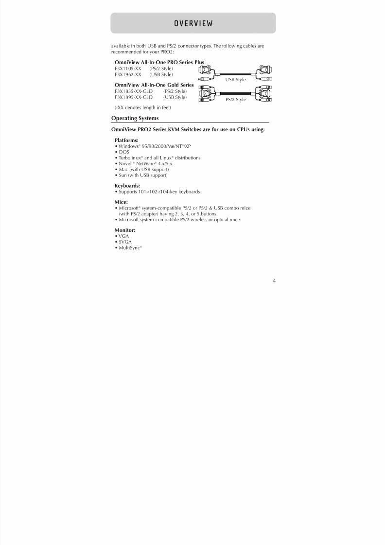
available in both USB and PS/2 connector types. The following cables are
recommended for your PRO2:
OmniView All-In-One PRO Series PlusF3X1105-XX (PS/2 Style)F3X1962-XX (USB Style)
OmniView All-In-One Gold SeriesF3X1835-XX-GLD (PS/2 Style)F3X1895-XX-GLD (USB Style)
(-XX denotes length in feet)
Operating Systems
OmniView PRO2 Series KVM Switches are for use on CPUs using:
Platforms:• Windows® 95/98/2000/Me/NT®/XP• DOS
• Turbolinux® and all Linux® distributions• Novell® NetWare® 4.x/5.x• Mac (with USB support)• Sun (with USB support)
Keyboards:• Supports 101-/102-/104-key keyboards
Mice:
• Microsoft® system-compatible PS/2 or PS/2 & USB combo mice(with PS/2 adapter) having 2, 3, 4, or 5 buttons
• Microsoft system-compatible PS/2 wireless or optical mice
Monitor:• VGA• SVGA• MultiSync®
OVERVIEW
USB Style
PS/2 Style

8/7/2019 pro2_manual
http://slidepdf.com/reader/full/pro2manual 7/37
5
OVERVIEW
Side View of the PRO2:
BANK DIP switch(may be located on theback in some models)
BANK 1O
NON
2 3 4 5 6 1 2 3 4FLASH
FLASH DIP switch(may be located on the backin some models)
F1DA108T

8/7/2019 pro2_manual
http://slidepdf.com/reader/full/pro2manual 8/37
6
OVERVIEW
USB
USB
04
03
Direct-accessport selector
LED for selectedport identification
Manual BANKscroll buttons
7-segment LED forselected BANK identificationAutoScan button
Master Input/Slave Output
Console VGA Computer VGA port
Console PS/2 mouse/keyboard ports
Computer PS/2mouse/keyboard ports
Computer USB port
DC power jack
Flash upgrade port
Slave Input
Back View of the PRO2:
F1DA108T
F1DA108T
Front View of the PRO2:

8/7/2019 pro2_manual
http://slidepdf.com/reader/full/pro2manual 9/37
7
OVERVIEW
Specifications
Part No.: F1DA104T, F1DA108T & F1DA116T
Power: 12-Volt DC, 1-Amp power adapter with center-pin positive polarity
Daisy-Chain: Maximum of 16 KVM Switches
Computer Connections Supported:4 (F1DA104T)8 (F1DA108T)16 (F1DA116T)
Keyboard Emulation: PS/2
Mouse Emulation: PS/2
Monitors Supported: VGA, SVGA, MultiSync, and LCD (optional adapter maybe required)
Max. Resolution: 2048x1536@85Hz
Bandwidth: 400MHz
Keyboard Input: 6-pin miniDIN (PS/2)
Mouse Input: 6-pin miniDIN (PS/2)
VGA Port: 15-pin HDDB typePort LED Indicators: 4 (F1DA104T)8 (F1DA108T)16 (F1DA116T)
Enclosure: Metal enclosure with high-impact plastic faceplate
Dimensions:
(F1DA104T) 11 x 1.75 x 6 inch (279mm x 44.5mm x 150mm)(F1DA108T)17.25 x 1.75 x 7.5 inch (438mm x 44.5mm x 190mm)(F1DA116T) 17.25 x 3.5 x 7.5 inch (438mm x 89mm x 190mm)
Weight:
(F1DA104T) 5.3 lbs. (2414.5 grams)(F1DA108T) 9.2 lbs. (4181.5 grams)(F1DA116T) 12 lbs. (5472.5 grams)
Operating Temp.: 32° to 104° F (0~40° C)
Storage Temp.: -4° to 140° F (20~60° C)
Humidity: 0-80% RH, non-condensing
Warranty: 5 years
Note: Specifications are subject to change without notice.

8/7/2019 pro2_manual
http://slidepdf.com/reader/full/pro2manual 10/37
8
Pre-Configuration
Where to Place the PRO2:The enclosure of the PRO2 is designed for standalone or rack-mountconfiguration. The 8- and 16-port PRO2s are natively rack-mountable instandard 19-inch server racks. Rack-mount hardware is included with theseswitches for a study rack installation. An optional rack-mount kit (F1D005) isavailable for use with the 4-Port PRO2.
Consider the following when deciding where to place the PRO2:
• whether or not you intend to use the direct-access port selectors;• the lengths of the cables attached to your keyboard, monitor, and mouse;• the location of your CPUs in relation to your console;• and the lengths of the cables you use to connect your computers to the PRO2.
Cable Distance Requirements:For PS/2 computers:VGA signals transmit best up to 25 feet. Beyond that length, theprobability of video degradation increases. For this reason, we recommend
that the length of the cables between the PRO2 and the connected computersdoes not exceed 25 feet.
Note:If you need your console to reside further than 25 feet from the PRO2, werecommend using the Belkin CAT5 Extender (F1D084) with a standard CAT5UPT cable. By using this device, you may increase the distance betweenyour PRO2 and your keyboard, mouse, and monitor by as much as 500 feetwithout risking signal degradation.
For USB computers:USB signals can be transmitted up to 15 feet between the PRO2 and the CPU.Beyond 15 feet, the probability of signal failure is likely, and this may causethe device to fail.
Cautions and Warnings:Avoid placing cables near fluorescent lights, air conditioning equipment, ormachines that create electrical noise (e.g., vacuum cleaners).
INSTALLATION

8/7/2019 pro2_manual
http://slidepdf.com/reader/full/pro2manual 11/37
9
INSTALLATION
Step-by-Step Installation Guide
Cautions and Warnings:Before attempting to connect anything to the PRO2 or your computer(s),please ensure that everything is powered off. Plugging and unplugging cableswhile computer(s) are powered on may cause irreversible damage to thecomputer(s) and/or the PRO2(s). Belkin Components is not responsible fordamage caused in this way.
Installing the PRO2 into a Server Rack:
Bracket Installation (F1DA108T and F1DA116T only)Eight- or 16-Port PRO2s include adjustable mounting brackets ideal forinstallation in 19-inch racks. The mounting brackets feature three adjustmentpositions to allow the faceplate of the PRO2 to mount flush to your rack-mountedservers, or to the rack. Please follow these simple steps to achieve the desiredadjustment. The 4-Port PRO2 requires an optional mounting kit (F1D005).
1. Remove the adjustable brackets from the box. (The adjustable bracketsallow you to set the PRO2’s face flush with the ends of the rails or toextend the PRO2 past the front of the rails).
2. Determine how far you would like the PRO2 to protrude from the rack.Select a bracket-hole scheme.
3. Attach the bracket to the side of your PRO2 using the Phillips screwsprovided. (Refer to diagram above).
4. Mount the PRO2 to the rack rail assembly.
Note: If this PRO2 will be daisy-chained to another PRO2, set the BANK address prior to installing on a rack. Refer to the section in this user manual labeled “Connecting Multiple PRO2s (Daisy-Chaining)”.

8/7/2019 pro2_manual
http://slidepdf.com/reader/full/pro2manual 12/37
10
INSTALLATION
Your PRO2 is now mounted securely into the bracket and you are ready to
connect cables to the back of the unit.
Note for Belkin PRO Series owners (F1D104-OSD, F1D108-OSD,F1D116-OSD): Installation for the PRO has changed. Please follow thisinstallation manual completely to assure proper installation. Failure to doso may result in keyboard or mouse errors, and/or faulty operation.
Single PRO2 Installation
This section provides complete instructions for the hardware setup of a singlePRO2. (F1DA104T, F1DA108T, and F1DA116T)
PS/2 Installation:Keyboard, Video, and Mouse Connections
Connect the Console:1. Connect the monitor to the
PRO2. Attach your monitorcable to the HDDB15 femaleport on the back of the PRO2labeled "Console VGA".
2. Connect the PS/2 keyboardcable to the keyboard porton the back of the PRO2in the "Console" section.
3. Connect the PS/2 mouse
cable to the mouse port onthe back of the PRO2 inthe "Console" section.
Attach the power supply to the DC power jack labeled "DC 12V, 1A" locatedon the rear of the PRO2. Once the power is connected to a power source, theLED for port 01 will begin flashing. Sequentially push the direct-access portselectors for ports 01 through 08 (04 for F1DA104T and 16 for F1DA116T).The corresponding LED should flash as each button is pressed, indicating that
the port is ready for connecting your servers (computer connection).
VGA VGA VGA VGA VGA VGA VGA VGAVGA
08
0808
USB
USB USB USB USB
USBUSBUSB07 07
07 06 06
06
06
05 05
05 04
04
04
03 03
03 02
02
02 01
0101
1 2 3
4 5 6
7 8 9
+
-= /
0
numlock
caplo c k p gup
return
shif t c lt
alt
delete
P [ ]
'";:LK
=-098 PG UP PG DNHOME
HELP CAPS `
ESC
<>
^
+
OPT PC
F9 F10 F11
7654321
VGA VGA VGA VGA VGA VGA VGA VGAVGA
08
08 08
USB
USB USB USB USB
USBUSBUSB07 07
07 06 06
06
06
05 05
05 04
04
04
03 03
03 02
02
02 01
0101

8/7/2019 pro2_manual
http://slidepdf.com/reader/full/pro2manual 13/37

8/7/2019 pro2_manual
http://slidepdf.com/reader/full/pro2manual 14/37
12
INSTALLATION
1. Using a USB KVM Cable (Belkin part# F3X1962-XX or F3X1895-XX-GLD),
plug the male VGA connector into the VGA port on the computer.Connect the other end (the female connector) of the VGA cable tothe back of the PRO2 for the appropriate port you wishto connect to (for example, "VGA 02").
2. Connect theUSB cable's"A-type"connector to an available USB port on your USB
computer. Connect the other end of the USB cable(with the "B-type" connector) to the correspondingport on the back of the PRO2 (for example, "USB 02").
NOTE: We recommend you attach the KVM cable directly to a free USB porton your computer.
Repeat steps 1 and 2 above for each additional USB computer you wishto connect.
Connecting Multiple PRO2s (Daisy-Chaining)
You can daisy-chain up to 16 PRO2s together, giving a server administratorcontrol over a maximum of 256 computers. When daisy-chained together,each unit is referred to as a "BANK" and assigned an address. The Consolekeyboard, mouse, and monitor connects to BANK 00 and is referred to as the"Master" switch. BANKs 01 through 15 are referred to as "Slave" switches.
Note: A daisy-chain cable (F1D108-CBL) is required to daisy-chain each
PRO2 and is available through your Belkin reseller or online at belkin.com.
All PRO2s feature a “BANK DIP” switch. The BANK DIP switch is used for properidentification and use of PRO2s in a single-unit or daisy-chain configuration.
• For a single-unit configuration, set the BANK DIP switch on the PRO2 to the“Master” (BANK address 00) setting. This is the factory default setting.
• For multi-unit configuration, the BANK DIP switch on the Master unit mustbe set to “BANK address 00”. Slave units must be set to a unique BANKaddress (from 01 through 15). Refer to the chart below for BANK DIPswitch settings.
VGA VGA VGA VGA VGA VGA VGA VGAVGA
08
08 08
USB
USB USB USB USB
USBUSBUSB07 07
07 06 06
06
06
05 05
05 04
04
04
03 03
03 02
02
02 01
0101

8/7/2019 pro2_manual
http://slidepdf.com/reader/full/pro2manual 15/37
13
INSTALLATION
BANK DIP Switch Configuration Chart
DIP SWITCH# BANK ADDRESS
1 2 3 4 5 6
ON ON ON ON ON ON BANK 00 MASTER (default)
ON ON OFF ON ON ON BANK 01 SLAVE
ON ON ON OFF ON ON BANK 02 SLAVE
ON ON OFF OFF ON ON BANK 03 SLAVE
ON ON ON ON OFF ON BANK 04 SLAVEON ON OFF ON OFF ON BANK 05 SLAVE
ON ON ON OFF OFF ON BANK 06 SLAVE
ON ON OFF OFF OFF ON BANK 07 SLAVE
ON ON ON ON ON OFF BANK 08 SLAVE
ON ON OFF ON ON OFF BANK 09 SLAVE
ON ON ON OFF ON OFF BANK 10 SLAVE
ON ON OFF OFF ON OFF BANK 11 SLAVE
ON ON ON ON OFF OFF BANK 12 SLAVEON ON OFF ON OFF OFF BANK 13 SLAVE
ON ON ON OFF OFF OFF BANK 14 SLAVE
ON ON OFF OFF OFF OFF BANK 15 SLAVE
Note: “On” is the down position.
Example:
Four 8-Port PRO2s (F1DA108T) are daisy-chained together for controllingup to 32 computers. The DIP switch on the Master unit is set to “BANK 00”(factory default) and the Slave units are each set to a unique BANK(between 01 and 15).

8/7/2019 pro2_manual
http://slidepdf.com/reader/full/pro2manual 16/37
14
Installation
Before You Begin:1. Make sure that all computers are powered off and that each PRO2 has
been assigned a unique BANK address.
2. Place Master and Slave switches in the desired location. Make sure allare turned off and unplugged from the power source.
3. Connect the Console monitor, keyboard, and mouse to the Consoleports of the Master switch or Bank 00, as described previously in thisinstallation guide.
Connecting the Master Switch to the First Slave Switch:4. Using the daisy-chain cable (F1D108-CBL), connect one end of the cable
to the “Master Input/Slave Output” port on the Master switch (BANK 00).
5. Connect the other end of the daisy-chain cable to the “Master Input/SlaveOutput” port of the first Slave switch (BANK 01).
Adding Additional Slave Units:6. Using the daisy-chain cable (F1D108-CBL), connect one end of the cable
to the available daisy-chain port labeled “Slave Input” on the Slave switch(for example, BANK 01).
7. Connect the other end of the daisy-chain cable to the “Master Input/SlaveOutput” port of the Slave switch that you are adding(for example, BANK 02).
8. Repeat steps 6 and 7 for additional PRO2s you wish todaisy-chain together.
INSTALLATION

8/7/2019 pro2_manual
http://slidepdf.com/reader/full/pro2manual 17/37
15
Example of Daisy-Chain Configuration:
Connecting the Computers:9. Connect all computers to the Master and Slave switches. Refer to
“Single PRO2 Installation” on page 10 for instruction on how to connectthe Console and the computers to the PRO2.
10. Connect the power supply to the Master switch. Power up the Masterswitch. You should see the Master switch light up and display the digits“00”, indicating its BANK address.
11. Power up the Slave switches sequentially, beginning with Bank 01, byconnecting each unit’s power supply. Each switch should display itscorresponding BANK address number as it is powered up.
Note: If the PRO2s do not enumerate correctly, reset the Master switch(BANK 00) by simultaneously pressing the "BANK +" and "BANK –" buttons.You can also reset the Master switch to detect newly added Slave switches.If the switches still do not enumerate correctly, check that all switches havethe correct BANK address assigned to them and that all daisy-chain cablesare connected properly.
12. Verify that the Master unit has detected all Slave switches by scrolling
through the BANKS using the BANK up and BANK down buttons.If all Slave switches are detected properly, the LED display on the Masterswitch will register and display the attached Slave switch’s BANK address.
INSTALLATION
VGA VGA VGA VGA VGA VGA VGA VGAVGA
08
08 08
USB
USB USB USB USB
USBUSBUSB07 07
07 06 06
06
06
05 05
05 04
04
04
03 03
03 02
02
02 01
0101
VGA VGA VGA VGA VGA VGA VGA VGAVGA
08
08 08
USB
USB USB USB USB
USBUSBUSB07 07
07 06 06
06
06
05 05
05 04
04
04
03 03
03 02
02
02 01
0101
VGA VGA VGA VGA VGA VGA VGA VGAVGA
08
08 08
USB
USB USB USB USB
USBUSBUSB07 07
07 06 06
06
06
05 05
05 04
04
04
03 03
03 02
02
02 01
0101
VGA VGA VGA VGA VGA VGA VGA VGAVGA
08
08 08
USB
USB USB USB USB
USBUSBUSB07 07
07 06 06
06
06
05 05
05 04
04
04
03 03
03 02
02
02 01
0101
Slave Input
Master Input /Slave Output
Slave Input
Master Input /Slave Output
Slave Input
Master Input /Slave Output
Slave Input
Master Input /Slave Output
cable 1
cable 2
cable 3
Master unit (BANK 00)
Slave unit (BANK 01)
Slave unit (BANK 02)
Slave unit (BANK 03)

8/7/2019 pro2_manual
http://slidepdf.com/reader/full/pro2manual 18/37
16
USING YOUR PRO2
Powering up the Systems
Once all cables have been connected, power up the computers that areattached to the PRO2. All computers can be powered on simultaneously. ThePRO2 emulates both a mouse and keyboard on each port and allows yourcomputer to boot normally.
The computer connected to port “1” will be displayed on the monitor. Checkto see that the keyboard, monitor, and mouse are working normally. Proceedto do this with all occupied ports to verify that all computers are connected
and responding correctly. If you encounter an error, check your cableconnections for that computer and reboot. If the problem persists, pleaserefer to the Troubleshooting section in this manual.
Using Your PRO2:
Now that you have connected your Console and computers to your PRO2,it is ready for use.
Select connected computers by either the direct-access port selectors, located onthe front panel of the PRO2, using the On-Screen Display, or by using hot keycommands through the Console keyboard. It takes approximately 1-2 seconds forthe video signal to refresh after switching computers. Re-synchronization of themouse and keyboard signals also occurs. This is normal operation and ensuresthat proper synchronization is established between the Console and the con-nected computers.

8/7/2019 pro2_manual
http://slidepdf.com/reader/full/pro2manual 19/37
17
Selecting a Computer Using Keyboard Hot Key Commands:
Switch to the next or previous port with simple keyboard key sequencesusing the “Scroll Lock” key and either the up or down arrow keys. To sendcommands to the PRO2, the “Scroll Lock” key must be pressed twice withintwo seconds. The PRO2 will beep, confirming that it is in hot key mode.Next, press the up or down arrow keys, and the PRO2 will switch to eitherthe prior port or the next port.
With a single-switch configuration (no daisy-chained switches), you canswitch directly to any port by entering the two-digit number of the port youwish to access. For example, if you press “Scroll Lock”, “Scroll Lock”, “02”,the PRO2 will switch to the computer on port 2 located on BANK 00.
Note: You will have approximately five seconds to complete eachhot key sequence.
With daisy-chain switch configuration, you can switch between BANKs bypressing “Scroll Lock”, “Scroll Lock”, “Page Up”, to switch to the previous BANK.Press “Scroll Lock”, “Scroll Lock”, “Page Down”, to switch to the next BANK.
USING YOUR PRO2
Page
Up
Switch to BANK 00, Port 2(02)
+
Page
Down
+
+ + + +Switch to previous BANKPage Up Switch to next BANK Page Down
+ +Switch to next active portDown arrow Switch to previous active portUp arrow
+ +

8/7/2019 pro2_manual
http://slidepdf.com/reader/full/pro2manual 20/37
18
USING YOUR KVM SWITCH
With a daisy-chain switch configuration, you can switch directly to any port
on any BANK by pressing “Scroll Lock”, “Scroll Lock”, BANK address, andport number. For example, if you press “Scroll Lock”, “Scroll Lock”, “03”,“05”, the computer on BANK 03, Port 5 will become active.
AutoScan Mode:
Pressing the AutoScan button on the PRO2 will activate the AutoScanfunction. In AutoScan mode, the PRO2 remains on one port for a pre-setnumber of seconds, before switching to the next computer. This timeinterval can be adjusted via the On-Screen Display menu.
Note: There is no mouse or keyboard control in AutoScan mode. This isnecessary to prevent data and synchronization errors. If the user is using themouse or keyboard when the PRO2 is switching between ports, data flow may become interrupted and could result in erratic mouse movement and/orwrong-character input when using the keyboard.
Press any button on the front panel or any key on the keyboard todisable AutoScan.
Selecting a Computer Using Direct-Access Port Selectors:
You can directly select which computer you wish to control by pressing thedirect-access port selector next to the corresponding port. The LED will illuminate
to indicate the port is currently selected. If you are installing multiple PRO2s thatare daisy-chained, use the BANK scroll keys located on the front panel of theMaster switch to access other computers that are connected to the Slave switches.
BANK Up and BANK Down Scroll Buttons:Pressing the BANK + and BANK – scroll buttons on the Master switch willallow you to switch between the daisy-chained PRO2s. Pressing bothbuttons simultaneously will reset the PRO2.
The BANK + button will take you to the next BANK. For example, when youare at the Master switch (BANK 00) and want to check computers on BANK02, pressing the BANK + button will take you to BANK 02. As a default, the
3 5+++

8/7/2019 pro2_manual
http://slidepdf.com/reader/full/pro2manual 21/37
19
first active computer will be displayed on the Console monitor. Use the
direct-access port selectors to go to the desired computer on BANK 02.The “BANK –” button will take you to the previous BANK. For example,when you are at BANK 02 and want to check computers in BANK 01.Pressing the “BANK –” button will take you to BANK 01. As default, thefirst active computer will be displayed on the Console monitor. Use thedirect-access port selectors to go to the desired computer on BANK 01.
Keyboard Hot Key Commands:Conveniently command the PRO2 to switch ports through simple keyboardkey sequences. To send commands to the PRO2, the “Scroll Lock” key mustbe pressed twice within two seconds. You will hear a beep for confirmation.Below is a complete list of hot key commands:
Note: you will have approximately five seconds to complete eachhot key sequence.
SL SL Up Arrow Switch to PREVIOUS ACTIVE port
SL SL Down Arrow Switch to NEXT ACTIVE port
SL SL Page Up Switch to PREVIOUS BANK(By default, selects first active port on the
BANK)
SL SL Page Down Switch to NEXT BANK
(By default, selects first active port on the
BANK)
SL SL Y Directly switches to PORT Y on BANK 00
(Single-Switch Configuration) Y=01 to 16
SL SL X Y Directly switches to PORT Y on BANK X(Daisy-Chain Configuration) (X=00 to 15) (Y=01 to 04 for F1DA104T)
(X=00 to 15) (Y=01 to 08 for F1DA108T)
(X=00 to 15) (Y=01 to 16 for F1DA116T)
SL SL Delete Reset On-Screen Display menu
SL SL S Disable sound in AutoScan mode
SL SL Space Bar Activate On-Screen Display
SL SL A Enable AutoScan mode
(Refer to AutoScan button)
USING YOUR PRO2

8/7/2019 pro2_manual
http://slidepdf.com/reader/full/pro2manual 22/37
20
USING YOUR PRO2
On-Screen Display Menu Control:
To access the On-Screen Display (OSD) menu, press “Scroll Lock”, “ScrollLock”, and the space bar. Immediately, the OSD overlay screen will appear.The superimposed menu screen is generated by the PRO2, and does not affectyour computers or software function in any way.
The main OSD menu is shown below. It displays the current selected BANK. If you have only one PRO2, it will display “BANK 00”.
A “✹“ symbol indicates that the computer is powered.
If a computer is connected and is powered up, but the OSD menu doesnot display a ✹ symbol, you will have to reset the PRO2 to re-detect the
powered computer. This is done by simultaneously pressing the “BANK +”and “BANK –” buttons on the front panel.
(): SELECT: Navigate to different computers in the same BANK.
(PGUP/DN): BANK: Select previous BANK by pressing the “Page Up” key andnext BANK by pressing the “Page Down” key.
(Insert): RENAME: Name each computer (up to 15 characters).
(ENTER): SAVE: Save the content input.
(TAB): SETUP: Open “Setup” menu.
(ESC): EXIT: Exit the On-Screen Display.
Setup Menu
Main Menu

8/7/2019 pro2_manual
http://slidepdf.com/reader/full/pro2manual 23/37
21
AutoScan Time:
Specifies the amount of time the PRO2 remains on a port before switchingto the next port while in AutoScan mode. You may select different timeintervals7, 15, 30, or 60 seconds. Use the OSD to set the AutoScantime interval.
OSD Display Time:Specifies the amount of time the OSD menu is displayed. Also specifies theamount of time the “Port Identification” tag displays on-screen after making aport selection. You may choose 7, 15, 30, or 60 seconds.
For both settings, you may use the arrow keys to navigate. After you haveselected the desired time intervals, push “Enter” key to save the entry.Press the “ESC” key to go back to the original OSD menu screen.Press the “ESC” key again to exit the On-Screen Display completely.Once you have selected a computer on the menu, press “Enter” to switchto that port.Note: If there are Slave units connected, and the AutoScan time and OSDdisplay time settings are set on the Master unit, the settings will also apply toall slave units.
Updating Firmware:To update your firmware, download the appropriate firmware file and utilityfrom belkin.com. The utility automatically guides you through the process of updating the firmware on your PRO2.
Cautions and Warnings:We strongly recommend that you update your firmware only if you are
currently experiencing mouse and keyboard problems with your PRO2, asreconfiguring software may lead to unexpected operational problems.Please contact Belkin Tech Support if you need assistance.
To update the firmware, you will need the following items:1. A separate computer running Windows 95, 98, or Me. This computer must
not be connected to the CPU ports on the PRO2.2. An available parallel port on the computer.3. A custom flash cable (DB25 Male-to-RJ45; included with purchase) that
connects between the PRO2 and the computer.4. Firmware update files available at belkin.com.
USING YOUR PRO2

8/7/2019 pro2_manual
http://slidepdf.com/reader/full/pro2manual 24/37
22
USING YOUR PRO2
Connecting Computers:1. Connect a keyboard, monitor, and mouse to the computer you prepared forfirmware update. It must run Windows 95, 98, or Me.
2. Connect the power adapter to the PRO2. Be sure that all connected com-puters are powered off at this moment.
3. Connect the custom flash cable (DB25 Male-to-RJ45; included withpurchase). Connect one end of DB25 to your computer’s parallel portand the other end of RJ45 to the PRO2 flash upgrade jack.
Setting the PRO2 into Flash Mode:The PRO2 has four Flash DIP switches:
DIP Switch Firmware1 2 3 4ON OFF OFF OFF MainOFF ON OFF OFF OSDON ON OFF OFF Keyboard 1OFF OFF ON OFF Mouse 1ON OFF ON OFF (F1DA116T Only) Keyboard 2
OFF ON ON OFF (F1DA116T Only) Mouse 2
The DIP switch should be set to the specified settings when you areattempting to update a particular firmware. For example, set DIP switch 1 to“ON” to flash update the main firmware of the switch.
Note: F1DA116T requires that you flash update two firmwares for the mouseand keyboard, separately.
1. Once the above steps have been completed, run the Flash software exe-cutable. Make sure that the appropriate Flash DIP switch is set to the “on”position. Only one firmware can be flashed at one time.
2. After the Flash update has been completed unplug the power supply fromthe PRO2.
3. Set all DIP switches to the Off position.
4. You are now ready to use your PRO2 or continue flashing a different
component if necessary.

8/7/2019 pro2_manual
http://slidepdf.com/reader/full/pro2manual 25/37
23
BELKIN KVM SWITCHES AND ACCESSORIES
OmniView KVM Switches
OmniView E Series. This series of desktop OmniView KVM Switches allowsyou to control two or four PS/2 computers from one Console and makesswitching between computers more convenient. Designed for compatibilitywith your PS/2 platform, it reduces desktop clutter and provides a simple, reli-able solution at a lower price point.
The E Series KVM Switch supports high-quality resolution of up to2048x1536@85Hz through a 400MHz bandwidth when used with coaxialVGA cabling. This means that Belkin OmniView products offer the highestresolution without compromising the quality of the display. Power for theKVM Switch draws off the keyboard, so that the Switch requires no additionalpower supply and fewer cables. Standard E Series features include: hot keyfunctionality; keyboard and PS/2 emulations for error-free boot up; and aBelkin Two-Year Warranty.
F1DB102P E Series 2-Port KVM Switch PS/2 OnlyF1DB104P E Series 4-Port KVM Switch PS/2 Only
OmniView SOHO Series with Audio. This innovative design providesbuilt-in cable management and saves space, while adding a whole newsculpted look to your desktop. The SOHO Series Switches allow you tocontrol two or four PS/2 computers from one Console. You'll enjoy thegreatest interface flexibility with PS/2 and USB combination Switches. Theyoffer you expanded compatibility with either interface, or both, along withthe additional convenience of manual push-button port selection on the face
of the device. Switch between speakers and microphones without having
to unplug and re-plug them when switching computers. The flash featureallows users to download firmware updates and ensure compatibility withthe latest computers and devices. The enclosure design builds in cablemanagement and the Switches are self-powered, so they require no externalpower supply and work with fewer cables. High-quality resolution of up to2048x1536@85Hz is supported through a 400MHz bandwidth by theOmniView SOHO Series with Audio KVM Switch when used with coaxialVGA cabling, offering the highest resolution without compromising the qualityof the display. Other standard features found on this unit include: hot key
functionality; keyboard and PS/2 emulations for error-free boot up; and aBelkin Five-Year Warranty.

8/7/2019 pro2_manual
http://slidepdf.com/reader/full/pro2manual 26/37
24
BELKIN KVM SWITCHES AND ACCESSORIES
F1DS102P SOHO Series 2-Port KVM Switch with Audio PS/2 OnlyF1DS104P SOHO Series 4-Port KVM Switch with Audio PS/2 OnlyF1DS102T SOHO Series 2-Port KVM Switch with Audio PS/2 & USBF1DS104T SOHO Series 4-Port KVM Switch with Audio PS/2 & USB
OmniView PRO2 Series. The OmniView PRO2 Series KVM Switches deliverreliability, performance, and centralized control necessary for today’senterprise environment. This series of KVM Switches enables you to controlmultiple platform servers from a single Console. Available in the desktop-style,4-port, and the 19-inch rack-mountable 8- and 16-port models, the OmniView
PRO2 Series KVM Switch expands easily for full control of as many as 256CPUs through dedicated daisy-chain ports. Video resolutions of up to1600x1200@65Hz are supported through a 400MHz bandwidth. On-ScreenDisplay allows you to name and select attached servers using an on-screeninterface. Switch between ports by using hot key commands or direct-accessport selectors. The Omniview PRO2 Series KVM Switches use standard cablesfor easy installation; include a 12-Volt DC, 1-Amp power supply; and arebacked by a Belkin Five-Year Warranty.
F1DA104T PRO2 Series 4-Port KVM Switch PS/2 & USBF1DA108T PRO2 Series 8-Port KVM Switch PS/2 & USBF1DA116T PRO2 Series 16-Port KVM Switch PS/2 & USB
OmniView MATRIX2 Series. The OmniView MATRIX2 Series 2x8- and2x16-Port KVM Switches enable two administrators to control up eight or16 PS/2 and USB platform servers, separately or simultaneously. Each useroperates a separate console following a different bus path for completeindependence from the other console. The OmniView MATRIX2 Series KVM
Switch expands easily for full control of as many as 256 computers throughdedicated daisy-chain ports and is natively rack-mountable for server roomenvironments. Video resolutions of up to 2048x1536@85Hz are supportedthrough a 400MHz bandwidth. On-Screen Display allows you to name andselect attached servers using an on-screen interface. Switch between ports byusing hot key commands or direct-access port selectors. The OmniViewMATRIX2 Series KVM Switches use standard cables for easy installation;include a 12-Volt DC, 1-Amp power supply; and are backed by a BelkinFive-Year Warranty.
F1DM208T MATRIX2 Series 2x8-Port KVM Switch PS/2 & USBF1DM216T MATRIX2 Series 2x16-Port KVM Switch PS/2 & USB

8/7/2019 pro2_manual
http://slidepdf.com/reader/full/pro2manual 27/37
25
BELKIN KVM SWITCHES AND ACCESSORIES
OmniView All-In-One KVM Cables
OmniView All-In-One KVM Cables provide you with the quality connectionsnecessary to set up your KVM solution. Each kit provides the proper cablesand connectors to complete the installation of a Belkin OmniView KVM Switch.
OmniView All-In-One KVM Cables feature sturdy construction, withstrain-relief construction and PVC overmolding to prevent data loss. Useof 20-gauge wire delivers the high-performance cable that users have cometo identify with the Belkin name. A ferrite bead reduces electromagneticand radio frequency interference (EMI/RFI). PC99 color-coded connectorsand modified thumbscrews have been added for easier installation.
Gold Series. These cables are known for their 24k gold-plated connectorsand black Flextec™ jackets, and offer the highest-performance possible. The24k gold-plated connectors maximize longevity and signal integrity, and offercorrosion resistance. The Gold Series includes a custom 15-pin, coaxial VGAcable to support image clarity for the highest-resolution applications. TheGold Series is available in PS/2 and USB styles.
F3X1835-XX-GLD PS/2 (available in lengths of 6, 10, 15, and 25 feet)F3X1895-XX-GLD USB (available in lengths of 6, 10, and 15 feet)
PRO Series Plus. The PRO Series Plus Cables are high-performancecables built to exacting standards. They receive and transmit data throughnickel-plated connectors. The industry-standard 14-pin, coaxial VGA cablingwas designed to support image clarity for high-resolution applications. Thegray jacket bends into even the tightest crawl spaces for an excellent fit.The PRO2 Series Plus Cable is available in PS/2- and USB-style cable kits.
F3X1105-XX PS/2 (available in lengths of 6, 10, 15, and 25 feet)F3X1962-XX USB (available in lengths of 6, 10, and 15 feet)
(-XX denotes length in feet)

8/7/2019 pro2_manual
http://slidepdf.com/reader/full/pro2manual 28/37
26
BELKIN KVM SWITCHES AND ACCESSORIES
OmniView Accessories and Adapters
Belkin KVM technology includes various accessories and adapters to completeyour KVM solution. The Adapter Series converts Mac, Sun, or USB keyboards,video, and mouse signals into PS/2 and VGA.
F1D080The OmniView PS/2 Mac Adapter™ converts a Macintosh®
computer with a 4-pin ADB™ (Apple® Desktop Bus) and DB15connector into a PS/2 keyboard, HDDB15 VGA monitor, andPS/2 mouse.
F1D082The OmniView PS/2 Sun Adapter™ converts a Sun 8-pinkeyboard/mouse and 13W3 video into a PS/2 keyboard, PS/2mouse, and HDDB15 VGA monitor.
F1D084The OmniView CAT5 Extender enables you to control a PC orKVM Switch up to 500 feet away using standard UTP CAT5 cabling.
F1D087The OmniView Keyboard Extender allows you to extend yourkeyboard up to 250 feet away.
F1D088The OmniView VGA Monitor Extender bridges up to 250 feetof distance between your PC and monitor.
F1D089The OmniView Keyboard Splitter allows you to work with twokinds of PS/2 keyboards and pointing devices without swappingcables or rebooting the computer.
F1D090The OmniView Mouse Splitter allows you to work with two
kinds of PS/2 mice or trackballs without swapping cables orrebooting the computer.
F1D201The OmniView 2-Port Reverse KVM Switch gives two userscentral control of one PC from two sets of keyboards, monitors,and mice.
F2N017The Omniview PRO2 Series AT-to-PS/2 Keyboard Adapterallows you to connect a keyboard with an AT-style connector to a
computer with a PS/2-style connector.

8/7/2019 pro2_manual
http://slidepdf.com/reader/full/pro2manual 29/37
27
PRO2 SERIES FAQs
Q: What operating systems does the PRO2 support?
A: The PRO2 will support any operating system that runs on a PS/2 andUSB platform. It will also work with non-USB Sun and Mac operatingsystems using the appropriate adapters (OmniView PS/2 Sun Adapter[F1D082], OmniView PS/2 Mac Adapter [F1D080]). Operating systemsinclude, but are not limited to, DOS, Windows 95/98/2000/Me/NT/XP,Linux, and Mac OS.
Q: What does flash upgradeable mean?
A: With flash upgrade capability, you can update your PRO2 firmware atany time through a simple parallel connection. Internet upgrade capabilityensures that your PRO2 is always the most current version on the marketwith the latest features and enhancements. See the section on firmwareupdates in this manual (page 21) and when to use them.
Q: Does the PRO2 support Microsoft IntelliMouse®?
A: The PRO2 supports mice from Microsoft, Logitech®, Kensington®, etc., andBelkin. Please contact Belkin Technical Support for compatibility issuesyou may experience.
Q: How does the PRO2 allow the user to switch between ports?
A: The PRO2 supports three methods of port selection. The user canselect computers using specially designated keyboard hot keys, throughOn-Screen Display, or can independently access the desired port bypushing the direct-access port selectors.
PRO2 SERIES FAQ

8/7/2019 pro2_manual
http://slidepdf.com/reader/full/pro2manual 30/37
28
PRO2 SERIES FAQs
Q: How far can the computer be from the PRO2?
A: When using PS/2 connections, the PRO2 can be up to 25 feet away fromyour computer. If your computer needs to be more than 25 feet (7.5meters) from the PRO2, you can use the Belkin CAT5 Extender to extendyour PS/2 keyboard, PS/2 mouse, and monitor up to 500 feet away using astandard CAT5 UTP cable. When using USB connection between yourPRO2 and computer, we recommend that your computer be no more than15 feet (5 meters) from the PRO2.
Q: What is the maximum video resolution that the PRO2 supports?
A: The advanced video circuit in the PRO2 supports a maximum resolution of 2048x1536@85Hz.
Q: What video bandwidth does the PRO2 support?
A: The PRO2 supports 400MHz of video bandwidth.
Q: Can PS/2 and USB connections be used simultaneously on the same port?
A: No. You must use one or the other for each CPU’s dedicated port onthe PRO2.
Q: Do I have to install any software to use the PRO2?
A: No, the PRO2 does not require any drivers or software to be installed inyour computers. Simply connect all your computers to the PC ports on thePRO2, then attach one keyboard, monitor, and mouse to the Console portand it is ready for use.
PRO2 SERIES FAQ

8/7/2019 pro2_manual
http://slidepdf.com/reader/full/pro2manual 31/37
29
PRO2 SERIES FAQs
Q: Does the PRO2 require an AC adapter?
A: Yes, the PRO2 requires a 12-Volt DC, 1-Amp power adapter in order tofunction properly.
Q: Can I use the PRO2 to switch video signals only?
A: Yes, you may use the PRO2 to switch between video signals only withouthaving to connect the keyboard and mouse. The
keyboard and mouse should be connected directly to the computer thatthe video signal is taken from to ensure that your computer functionsproperly.
Q: Can I use the PRO2 on my Sun computer that supports USB?
A: Yes, the PRO2 works with any USB-capable computer.
Q: Does the PRO2 support Linux?
A: Yes, the PRO2 works with all Linux kernels configured for USB support.
Q: How long is the warranty for the PRO2?
A: The PRO2 comes with a five-year limited warranty.
TROUBLESHOOTING

8/7/2019 pro2_manual
http://slidepdf.com/reader/full/pro2manual 32/37
30
TROUBLESHOOTING
General
My computer does not boot when connected to the PRO2 but works finewhen I connect the keyboard, video, and mouse directly to the computer.
• Make sure that the keyboard and mouse cables are connected tightlybetween the PRO2 and the computer.
• Check that the keyboard and mouse cables are not crossed.
Video
I am getting ghosting, shadowing, or fuzzy images on my monitor.
• Check that all video cables are inserted properly.
• Check that the monitor you are using supports the resolution andrefresh-rate setting on your computer.
• Check that the graphics card you are using supports the resolution andrefresh-rate setting on your computer.
• Connect the monitor directly into the computer you are having troublewith to see if the problem still appears.
I am getting a black screen on my monitor.
• Check that all video cables are inserted properly.
• If you are not using a power adapter, check that the keyboard cable isconnected and inserted properly between the computer and PRO2 for theappropriate port.
• If you are using the PRO2 only for video switching and have no keyboardand mouse connection between the PRO2 and PC, you will need topurchase the optional 9V DC, 600mA power adapter (F1D065-PWR for
your appropriate country).
• Connect your monitor directly to the computer to verify that yourmonitor is functioning properly.
TROUBLESHOOTING

8/7/2019 pro2_manual
http://slidepdf.com/reader/full/pro2manual 33/37
31
TROUBLESHOOTING
Keyboard
The computer does not detect a keyboard and I get a keyboard error reported at boot up.
• Check that the keyboard cable between the PRO2 and the computer iscompletely connected. Tighten any loose connections.
• Try using a different keyboard.
• Try connecting the computer to a different port.
• If you are using the keyboard software that was included with your keyboard,uninstall it and then reinstall the standard Microsoft keyboard driver.
Mouse
The mouse is lost when I switch to a different port.
• Check that the mouse you are using is connected properly to the Console of the PRO2.
• If you are using a mouse driver that was included with your mouse,uninstall it and install the standard Microsoft mouse driver.
• Disconnect and reconnect the mouse cable attached to the channelwith which you are experiencing problems to re-synchronize the mouseconnection.
• Make sure the mouse works when directly plugged into the computer.
• If the computer is coming out of standby mode, allow up to one minute toregain mouse function.
• De-activate power-management schemes on the PC with which you areexperiencing problems.
• Try a different mouse.
TROUBLESHOOTING

8/7/2019 pro2_manual
http://slidepdf.com/reader/full/pro2manual 34/37
32
TROUBLESHOOTING
The mouse is not detected at boot-up.
• Check the cables and make sure that they are inserted correctly.
The computer boots up, but the mouse does not work.
• Make sure the mouse is plugged in properly.
• Make sure the mouse works when directly plugged into the computer.Rebooting may be necessary when trying this.
• Try a different mouse.
When I switch from one port to another, mouse movement iscompletely erratic.
• Make sure you do not have more than one mouse driver installed. Makesure that the driver is either for a standard PS/2 mouse or a Microsoftcomputer-compatible PS/2 mouse.
• Make sure you do not have any mouse drivers loaded in your CONFIG.SYSor AUTOEXEC.BAT files.
• Avoid moving the mouse or pressing the mouse button when switchingports on the PRO2.
• You can reset the mouse and resume proper mouse movement simply by
unplugging the mouse from the front of the PRO2 for about 2-3 seconds,and then plugging it in again.
TROUBLESHOOTING

8/7/2019 pro2_manual
http://slidepdf.com/reader/full/pro2manual 35/37
33
TROUBLESHOOTING
USB
I am connecting my computer to the USB PRO2 via USB and my keyboard and mouse do not work.
• Prior to connecting the USB PRO2, make sure that the HID USB driver isinstalled on each computer. (To install the HID USB driver, connect a USBmouse and USB keyboard to the computer. A Windows operating systemshould automatically install the drivers.)
Some of the keys on my keyboard are not functioning properly when I usea Mac computer.
• Because you are using a PC keyboard on a Mac system, a few of the optionkeys on your PC keyboard may be reversed. All major keys will functionas labeled.

8/7/2019 pro2_manual
http://slidepdf.com/reader/full/pro2manual 36/37

8/7/2019 pro2_manual
http://slidepdf.com/reader/full/pro2manual 37/37
Belkin Components B.V.
Starparc Building • Boeing Avenue 3331119 PH Schiphol-Rijk • The Netherlands
Tel: +31 (0) 20 654 7300Fax: +31 (0) 20 654 7349
Belkin Components, Ltd.
Unit 13 • Gatelodge Close • Round SpinneyNorthampton • Northants • NN3 8RX • United Kingdom
Tel: +44 (0) 1604678300Fax: +44 (0) 1604678330
Belkin Components
501 West Walnut StreetCompton • CA • 90220 • USA
Tel: 310.898.1100Fax: 310.898.1111
© 2002 Belkin Components. All rights reserved. All trade names areregistered trademarks of respective manufacturers listed.
Apple, Mac, and Macintosh are trademarks of Apple Computer, Inc.,registered in the U.S. and other countries.
Belkin Components, Ltd.
7 Bowen Cresent • West GosfordNSW 2250 • AustraliaTel: +61 (2) 4372 8600Fax: +61 (2) 4325 4277
P73782-A
belkin.com


