Embed Size (px)
Citation preview

Hitex Safety Solut ions
SafeTki t XC2388E Quick Start 4231.XC2388E, V1.1, 2012-02
PRO-SIL XC2000 Safety Concept Starter Ki t
XC2388E/CIC61508
Getting started with the Hitex PRO-SIL XC2000 SafeTkit
RELEASED

PRO-SIL XC2000 SafeTkit XC2388E
Edition 2012-02 Published by: Hitex (U.K.) Limited. University Of Warwick Science Park, Coventry, CV4 7EZ, UK © 2012 Hitex (U.K.) Limited. All Rights Reserved. Legal Disclaimer The information given in this document shall in no event be regarded as a guarantee of conditions or characteristics. With respect to any examples or hints given herein, any typical values stated herein and/or any information regarding the application of the product, Hitex (UK) Ltd. hereby disclaims any and all warranties and liabilities of any kind, including without limitation warranties of non-infringement of intellectual property rights of any third party.
Information
For further information on technology, delivery terms and conditions and prices, please contact the nearest Hitex Office (www.hitex.com).

PRO-SIL XC2000 SafeTkit XC2388E
RELEASED - SafeTkit XC2388E Quick Start 3 V1.1, 2012-02
Document Change History
Date Version Changed By Change Description
01/2/12 1.0 M Beach First version
15/2/12 1.1 A Wenlock Edit/Proof
We Listen to Your Comments
Is there any information in this document that you feel is wrong, unclear or missing?
Your feedback will help us to continuously improve the quality of this document.
Please send your comments (including a reference to this document) to:
PRO-SIL XC2000 SafeTkit XC2388E
RELEASED - SafeTkit XC2388E Quick Start 4 V1.1, 2012-02
Table of Contents
1 SafeTkit XC2388E Quick Start Guide Introduction ......................................................................... 8 1.1 SafeTkit XC2388E Introduction ............................................................................................................ 8 1.1.1 SafeTkit Board ...................................................................................................................................... 8 1.1.2 SafeTkit Software ................................................................................................................................. 8 1.2 SafeTkit XC2388E Major Functional Blocks ...................................................................................... 10
2 SafeTkit XC2388E Contents ............................................................................................................ 11 2.1 Default Configuration ......................................................................................................................... 11 2.2 Terms Used ........................................................................................................................................ 12
3 Installation Of SafeTkit Software And Documentation................................................................. 13 3.1 Introduction ......................................................................................................................................... 13 3.2 Installing The XC2388E Example Application .................................................................................... 14 3.3 Running The Installer ......................................................................................................................... 14 3.4 Working With Tasking Eclipse IDE ..................................................................................................... 18 3.4.1 Opening Eclipse ................................................................................................................................. 18 3.4.2 Building The Application ..................................................................................................................... 19
4 First Steps With The SafeTkit ......................................................................................................... 20 4.1 Basic Board Check ............................................................................................................................. 20
5 Running And Monitoring Applications – A First Session ............................................................ 21 5.1 Loading and Running The Example Application ................................................................................ 21 5.1.1 Preparations ....................................................................................................................................... 21 5.1.2 Real Time PRO-SIL XC2000 Testing And Monitoring With HiTOP54-TC ......................................... 22 5.2 Running The Example Application ..................................................................................................... 26 5.3 Monitoring The PRO-SIL XC2000 State ............................................................................................ 28 5.3.1 Understanding The SafeTcore Monitoring Window ........................................................................... 29 5.3.1.1 Monitoring CIC61508 SFRs ............................................................................................................... 29 5.3.1.2 Injecting Errors Into PRO-SIL XC2000 .............................................................................................. 31 5.3.1.3 Monitoring Real Errors ....................................................................................................................... 33 5.3.2 Restarting The Example Application After An Error Injection Test .................................................... 34
6 Configuring And Monitoring The CIC61508 .................................................................................. 35 6.1 Loading The PRO-SIL TestBench Driver Into The SafeTkit .............................................................. 36 6.2 Reloading The Demo Application Project .......................................................................................... 37 6.3 Starting The PRO-SIL TestBench ...................................................................................................... 38 6.4 Connecting To The SafeTkit Board .................................................................................................... 39 6.5 Live Update Of CIC61508 SFRs ........................................................................................................ 41 6.6 Entering The ACTIVE State ............................................................................................................... 43 6.7 Moving To The DISABLED State ....................................................................................................... 43 6.8 Restarting After DISABLED Mode ..................................................................................................... 44 6.9 Editing The CIC61508 Calibration Data In DFLASH.......................................................................... 45 6.10 The PRO-SIL TestBench DFLASH Editor .......................................................................................... 46 6.11 Enabling Voltage Monitor Channel A ................................................................................................. 48 6.11.1 Testing The New Configuration In The TestBench ............................................................................ 50 6.12 Entering The DISABLED State .......................................................................................................... 53 6.13 Reloading And Starting The PRO-SIL XC2000 Demo Application .................................................... 54 6.13.1 Testing The New CIC61508 Configuration With The PRO-SIL XC2000 Application ........................ 55 6.13.1.1 Restart PRO-SIL XC2000 With SENA In The Correct Position ......................................................... 55 6.13.1.2 Restart PRO-SIL XC2000 With SENA In An Incorrect Position ......................................................... 56 6.13.2 Restoring The SafeTkit To A Running Condition ............................................................................... 56 6.14 Conclusion .......................................................................................................................................... 58
7 PRO-SIL XC2000 Example Applications ........................................................................................ 59 7.1 Adapting The PRO-SIL XC2000 For The SafeTkit XC2388E ............................................................ 59 7.2 Advanced Example Application .......................................................................................................... 59 7.3 SafeTkit Default PRO-SIL XC2000 Configurations ............................................................................ 60

PRO-SIL XC2000 SafeTkit XC2388E
RELEASED - SafeTkit XC2388E Quick Start 5 V1.1, 2012-02
8 Further Information .......................................................................................................................... 61 8.1 Information On The Application Of PRO-SIL XC2000 TO ISO26262 ................................................ 61 8.2 Information On Importing And Exporting CIC61508 Calibration Data Sets ....................................... 61 8.3 Advanced CIC61508 Operation ......................................................................................................... 61 8.4 Detailed Operation And Configuration Of The PRO-SIL XC2000 Safety Driver ................................ 61
9 Appendix A: Programming The CIC61508 Firmware .................................................................... 62 9.1 Installing The CIC61508 Firmware ..................................................................................................... 62

PRO-SIL XC2000 SafeTkit XC2388E
RELEASED - SafeTkit XC2388E Quick Start 6 V1.1, 2012-02
List of Figures
Figure 1 XC2388E SafeTkit With CIC61508 Safety Monitor ............................................................................. 9 Figure 2 Block Diagram Of The XC2388ESafeTkit Board ............................................................................... 10 Figure 3 SafeTkit Demonstration Application Directory Structure (default) ..................................................... 17 Figure 4 Choosing the Eclipse workspace ....................................................................................................... 18 Figure 5 SafeTkit XC2388E Default Configuration, With Power And USB Cables .......................................... 20 Figure 6 Location Of HiTOP54-166 Project Files ............................................................................................. 22 Figure 7 Location Of JP401 .............................................................................................................................. 33 Figure 8 Reloading The Demo Application Project .......................................................................................... 37 Figure 9 Initialization Of The Internal DFLASH Edit Buffer .............................................................................. 39 Figure 10 Connected To The SafeTkit ............................................................................................................... 40 Figure 11 Live Update of CIC61508 SFR Contents ........................................................................................... 41 Figure 12 The CIC61508 Voltage Monitor Potentiometers ................................................................................ 45 Figure 13 The NVM Data Editing Tab ................................................................................................................ 46 Figure 14 Enabling Voltage Monitor Channel A ................................................................................................. 48 Figure 15 Reloading The Demo Application Project .......................................................................................... 54

PRO-SIL XC2000 SafeTkit XC2388E
RELEASED - SafeTkit XC2388E Quick Start 7 V1.1, 2012-02
List of Tables
Table 1 Default Jumper Settings ..................................................................................................................... 11 Table 2 CIC61508 SYSDIS_A/B/C states for NOT READY ........................................................................... 26 Table 3 CIC61508 SYSDIS_A/B/C states for READY .................................................................................... 26 Table 4 CIC61508 SYSDIS_A/B/C states for ACTIVE ................................................................................... 26 Table 5 CIC61508 SYSDIS_A/B/C states for DISABLED ............................................................................... 27 Table 6 CIC61508 SYSDIS_A/B/C states for READY .................................................................................... 42 Table 7 CIC61508 SYSDIS_A/B/C states for all states .................................................................................. 47

PRO-SIL XC2000 SafeTkit XC2388E
RELEASED - SafeTkit XC2388E Quick Start 8 V1.1, 2012-02
1 SafeTkit XC2388E Quick Start Guide Introduction
Welcome to the Hitex SafeTkit for the XC2388E. This document is intended to show you the main elements of the kit in a semi-guided manner. It contains specific instructions on how to operate the basic features whilst at the same time giving an introduction to the concepts and terminology used in the PRO-SIL XC2000 Safety System.
1.1 SafeTkit XC2388E Introduction
1.1.1 SafeTkit Board
The SafeTkit board has been designed to show the typical hardware configuration required for an ASIL-B(D) system based on the XC2300 and the CIC61508 Safety Monitor. It can also be configured as a platform for ASIL-B by using the XC2300 with the TLE6711 window-watchdog voltage regulator. To eliminate any common cause failure on the power supply, the XC2388E and CIC61508 have separate power regulators and each device is able to monitor the other‟s power supplies for early brown-out detection. The board can be configured in a “demonstration mode” (default) where the CIC61508 does not fully monitor the operation of the XC2388E. Analog voltages that in a real application would come from the XC2388E are in fact derived from simple potentiometers. Likewise, the XC2388E does not monitor the CIC61508 system disable pins or power supply. For early development of real applications, the board can be configured to run in accordance with the PRO-SIL Safety Concept. Here, the CIC61508 monitors the supply voltage (VDDP) to the XC2388E, plus its internally generated voltages VDDI and VDDIM. In turn, the XC2388E monitors the CIC61508‟s VDDP and VDDC plus checks the system disable pins for plausibility. To simulate a power fail on the XC2388E, a variable voltage supply can be used to check that the PRO-SIL system response is correct.
1.1.2 SafeTkit Software
The SafeTkit includes the PRO-SIL XC2000 Safety Driver Library to provide an ASL-B(D) capable software platform for custom developments. This library takes care of the configuration and start-up testing of the XC2388E as well as taking care of SPI communications with the CIC61508 safety monitor. PRO-SIL XC2000 includes the Infineon (Software Built-In Self Test) SBST which runs continuous checks of the CPU functionality at a gate level. The results of the checks are externally verified by the independently-powered CIC61508 safety monitor. In a real application, the CIC61508 would be able to disable the system via its System Disable pins, but on the SafeTkit it operates LEDs (it can also optionally reset the XC2388E). This meets one of the major requirements of ISO26262. PRO-SIL XC2000 is also able to monitor task execution times and calling sequences plus check the results of redundant calculations made by parallel threads in the XC23xx application.

PRO-SIL XC2000 SafeTkit XC2388E
RELEASED - SafeTkit XC2388E Quick Start 9 V1.1, 2012-02
16/32-bit XC2388E Future CPU with safety extensions
Expansion connector with all IO available
CIC61508 Safety Monitor for ASIL-B(D)
Separate power regulators for CIC61508 and XC2388E
CIC61508 monitors XC2388E VDDP, VDDI and VDDIM (optional)
2x CAN buffered interfaces brought out to 10-way pin headers
SPI EEPROM
2x CAN interfaces with transceivers
Flexray interface
XC2388E monitors CIC61508 VDDP and VDDC (optional)
XC2388E brown-out simulator
TLE6711 voltage regulator with window watchdog for ASIL-B only
USB/JTAG X2388E debug interface
USB virtual COMport
4 analog voltage sources for CIC61508
1 analog voltage source for XC2388E
Provision for full cross-linked voltage and system disable pin monitoring
SPI-driven LCD display
Power from USB or main power supply
10 user LEDs (P10)
System disable SYSDIS_X LEDs
Optional linking of CIC61508 and XC2388E resets to aid debugging
Figure 1 XC2388E SafeTkit With CIC61508 Safety Monitor
CIC61508 SENx Potentiometer Inputs LCD Display
XC2388E Reset
OptionalXC2364BSafety monitor
XC2388E User LEDS
CAN interfaces
DC Power
XC
2388E
bro
wn-o
ut
ERAY Interfaces
SYSDISA & B LEDs
SYSDISC LED
USB DebugCOMport
CIC61508Reset
XC2388E Analog
IO E
xpansio
n

PRO-SIL XC2000 SafeTkit XC2388E
RELEASED - SafeTkit XC2388E Quick Start 10 V1.1, 2012-02
1.2 SafeTkit XC2388E Major Functional Blocks
The major components of the board are shown below. The most important user-configuration jumpers are also given. Where there is a default or recommended setting for a jumper, it is shown with a narrow line. This is not an accurate representation of the SafeTkit schematic and is only intended for the purpose of identifying the major elements of the board.
Figure 2 Block Diagram Of The XC2388ESafeTkit Board
XC2388E
CIC61508
TLE7278 TLE4274
SENA
SENB
SENC
SEND
VDDP0
VDDP1
VDDIM
VDDI1
GND
3V3
VD
DP
VD
DC
JP405
JP404
JP403
JP402
RL
P5
.6
P5
.7
3V3
VREF
VA
RE
F
JP407
JP408
9V
ES
R2
WD
IP
8.1
JP
20
2
RO
3V3 0-3V3
Variable
JP201
BrownOut
R420
R413
R421
R414
SY
SD
IS_
A
SY
SD
IS_B
SY
SD
IS_C
ESR1
JP
409
GND
P8
.4
P8
.6
P8
.5
JP4002V5
1
1
1
1
1
1

PRO-SIL XC2000 SafeTkit XC2388E
RELEASED - SafeTkit XC2388E Quick Start 11 V1.1, 2012-02
2 SafeTkit XC2388E Contents
The SafeTkit XC2388E consists of:
1. Mains power supply unit 2. USB cable. 3. SafeTkit XC2388E evaluation board with CIC61508 Safety Monitor 4. An installation CD containing: 5. Tasking VX Toolset v3.0r3 evaluation version 6. HiTOP54-166 debugger and FLASH programmer 7. PRO-SIL XC2000 library for XC2388E 8. TARDISS TestBench GUI 9. TestBench driver supplied as a HEXfile and ELF file 10. A demonstration application (“Demo Application”) 11. An application suitable for further development (“Standard Application”) 12. PRO-SIL XC2000 User Manual and Quick Start Guide (this document)
This guide covers installing all the components and running a simple exercise. More detailed information on PRO-SIL XC2000 can be found in “PRO-SIL XC2000 UM v1.8.pdf”. A complete overview of the XC23xx, CIC61508 and PRO-SIL Safety Concept can be found in “XC2300_SafetyConcept_IFX.pdf”
2.1 Default Configuration
As shipped, the four SafeTkit voltage monitors are disabled (i.e. potentiometer settings are ignored by CIC61508). This is due to the calibration data in the CIC61508 and not to any board jumper settings. The DFLASH contents of the CIC61508 are as per “CIC61508_BuildSheet_VANIA30_SafeTkit.xls”. The jumpers are set in the following default configuration:
Jumper Default Comment
JP400 3V3 CIC61508 Reference Voltage
JP201 3V3 Fixed 3V3 supply for XC2388E
JP401 V_IN Use external power supply for CIC61508
JP200 VREG Use external power supply for XC2388E
JP405 1-2 SENA uses potentiometer as input
JP405 1-2 SENB uses potentiometer as input
JP403 1-2 SENC uses potentiometer as input
JP402 1-2 SEND uses potentiometer as input
JP406 Closed Connect CIC61508 and XC2388E resets together
JP407 Closed Connect XC2388E ADC P5.6 to CIC61508 Vddc
JP408 Closed Connect XC2388E ADC P5.7 to CIC61508 Vddp
JP409 Closed Connect CIC61508 SYSDIS_C to XC2388E ESR1
JP202 Closed Connect TLE7278 Reset Out to XC2388E ESR2
JP204 Closed Connect CIC61508 SYSDIS_A to A16 of X205A
JP203 Closed Connect CIC61508 SYSDIS_B to B16 of X205B
Table 1 Default Jumper Settings
It is recommended that you check that your board is configured this way to allow the demonstration application to run successfully.

PRO-SIL XC2000 SafeTkit XC2388E
RELEASED - SafeTkit XC2388E Quick Start 12 V1.1, 2012-02
2.2 Terms Used
Here are some basic terms used in this document.
SCII/SafeTcore-II: PRO-SIL XC2000: safety subsystem running on the XC2388E.
Safety Path: The physical lines that allow the CIC’s SYSDIS pins to disable critical hardware or the XC2388E itself, in the event of a failure in either the CIC or the PRO-SIL XC2000.
ACTIVE mode: CIC61508 is controlling the safety path and the PRO-SIL XC2000 is correctly performing the opcode test.
DISABLED mode: The CIC61508 has detected a critical failure and has put the safety path into the disabled state.
PRO-SIL: PRO-SIL Safety System consisting of the SafeTcore-II safety subsystem on the XC2388E and the CIC61508 Safety Monitor device.
Opcode Sequence Test/Sequence Test: Test of the XC2388E CPU core that is verified via the external CIC61508 safety monitor, connected via SPI.
System Period: 6ms system period. The period of the opcode sequence test i.e. all 4 opcode sequence test SFRs will have been written within this period.
System Tick: 600us – basic heartbeat rate of the CIC61508.

PRO-SIL XC2000 SafeTkit XC2388E
RELEASED - SafeTkit XC2388E Quick Start 13 V1.1, 2012-02
3 Installation Of SafeTkit Software And Documentation
3.1 Introduction
The SafeTkit software is supplied on a CD, but it can also be installed from a CD image on your hard disk. To install from a CD, simply insert the CD into your PC‟s CD/DVD drive and allow it to initialize. If you are installing from an image of the CD on hard disk, simply click the installer executable “SETUP.EXE”. The installer welcome screen will appear momentarily and you should be left with the installer menu. The Quick Start Guide that follows this section assumes that you have installed all of the items listed below.
Tasking C166 VX v3.03 SafeTkit Evaluation Version
HiTOP54-166 Debugger
PRO-SIL XC2000 library and applications
PRO-SIL Testbench CIC61508 configuration tool We strongly recommend that you do this. Each of the items has its own sub-installer and each one will run automatically in sequence.

PRO-SIL XC2000 SafeTkit XC2388E
RELEASED - SafeTkit XC2388E Quick Start 14 V1.1, 2012-02
3.2 Installing The XC2388E Example Application
There is an example application supplied in the kit. It is loaded into the SafeTkit FLASH using the HiTOP54-166 debugger. “Demo_Application”: This is the PRO-SIL XC2000 reference application for the XC2388E SafeTkit, modified to provide information for the HiTOP SafeTcore monitoring windows. It demonstrates the basic features of an ASIL-B(D) application. It is intended for training and experimentation. The PRO-SIL XC2000 has been specially altered to allow it to run as an object library set, but still allowing some important configurations to be changed. This version will only run on the SafeTkit. To run PRO-SIL XC2000 on any other platform will require a proper Software Development Kit licence, available from Hitex. The example applications installer has its own user interface, which is described later. The applications are supplied as complete Tasking Eclipse project file systems, which will open directly in the supplied evaluation toolchain.
3.3 Running The Installer
When invoking the installer “PROSILXC2000v2.3bSK.exe”, this dialog appears. Clicking ‟Next‟ reveals the Infineon licence terms that cover the PRO-SIL XC2000 libraries contained in the installation.

PRO-SIL XC2000 SafeTkit XC2388E
RELEASED - SafeTkit XC2388E Quick Start 15 V1.1, 2012-02
If you agree to these conditions, select “I accept the agreement”, otherwise end the installation now. The default location for the application is “C:\Hitex\PRO-SIL XC2000\MAYFLOWER2.3bSK” but you can change this if you wish. However, we strongly recommend that you stay with the default location, at least until you are more familiar with the SafeTkit. Click „Next‟ to continue…

PRO-SIL XC2000 SafeTkit XC2388E
RELEASED - SafeTkit XC2388E Quick Start 16 V1.1, 2012-02
Click Copy to continue. The installation process will take only a few seconds to complete. It will finish with:

PRO-SIL XC2000 SafeTkit XC2388E
RELEASED - SafeTkit XC2388E Quick Start 17 V1.1, 2012-02
The directory structure created will look like:
Figure 3 SafeTkit Demonstration Application Directory Structure (default)
The contents of each directory is:
Application: Example PRO-SIL application that uses the source code version of PRO-SIL XC2000.
Buildsheets: CIC61508 calibration data buildsheet as a spreadsheet.
DemoApplication: Alternative form of the example application that uses a fixed library-based version of
PRO-SIL XC2000.
Docs: PRO-SIL XC2000 User Manual (Preliminary)
Firmware: HEX file for programming into CIC61508F or XC866 on the SafeTkit board. SCII_Source: PRO-SIL XC2000 source code and library creation project.

PRO-SIL XC2000 SafeTkit XC2388E
RELEASED - SafeTkit XC2388E Quick Start 18 V1.1, 2012-02
3.4 Working With Tasking Eclipse IDE
This section shows how to open and build the example application in the Tasking Eclipse IDE.
3.4.1 Opening Eclipse
Start the Tasking Eclipse. When asked for which workspace to use, Browse to “C:\Hitex\PRO-SIL XC2000\MAYFLOWER2.3bSK\Implementation_v303_Demo”, as shown below.
Figure 4 Choosing the Eclipse workspace
Eclipse will initialise and shown the Demo Application in the workspace:

PRO-SIL XC2000 SafeTkit XC2388E
RELEASED - SafeTkit XC2388E Quick Start 19 V1.1, 2012-02
3.4.2 Building The Application
The demonstration application can now be compiled and linked.
Do this by clicking on “Rebuild Project”. This will build the project. If the application has been successfully installed, you should see an error-free build result in the console window in Eclipse. Now Rebuild the User Application using the same procedure, so that you are ready to try and run it on the SafeTkit board.

PRO-SIL XC2000 SafeTkit XC2388E
RELEASED - SafeTkit XC2388E Quick Start 20 V1.1, 2012-02
4 First Steps With The SafeTkit
This section will check that the SafeTkit is in a workable condition, prior to loading new applications in the following section. It is assumed that the board is in the factory condition.
4.1 Basic Board Check
Check that the jumpers on your board are set as shown in the picture below. If any jumpers are incorrect, move them to the correct state. This default configuration has the board powered from the external power supply connector.
Figure 5 SafeTkit XC2388E Default Configuration, With Power And USB Cables
Turn the potentiometer to the right of the LCD display fully anti-clockwise. Connect the mains power supply jack to the jack socket and then attach the USB port on the board to a free USB port on your PC with the supplied cable. The yellow LED 3 should flash approximately once per second and the CIC61508‟s SYSDIS_A, SYSDIS_B and SYSDIS_C LED should be off. This indicates that the board is in a running condition and that the CIC61508 has reached the ACTIVE mode.
CIC61508 Output Status State Meaning
SYSDIS_A Off
ACTIVE SYSDIS_B Off
SYSDIS_C Off
If there appears to be no response and the SYSDIS_X LEDs do not change, it is possible that the CIC61508 firmware is not present in the device. Please refer to Appendix A for details on how to reprogram it.

PRO-SIL XC2000 SafeTkit XC2388E
RELEASED - SafeTkit XC2388E Quick Start 21 V1.1, 2012-02
5 Running And Monitoring Applications – A First Session
This session will load the Demo Application example, run it and show how the PRO-SIL monitoring windows in HiTOP54-TC are used. You will see how to verify that the internal safety tests are working correctly in real time. The next chapter covers how the PRO-SIL TestBench is used to monitor the behaviour and configuration of the CIC61508. It is recommended that you work through the steps given, reading the explanatory text as you go. This will provide a simple introduction to the basic concepts and terminology used in the SafeTcore system.
5.1 Loading and Running The Example Application
5.1.1 Preparations
Make sure that the following items have been installed from the supplied CD or CD image:
1. Tasking Eclipse C166 VX v3.0r3 Evaluation Version 2. HiTOP54-166 SafeTkit Evaluation Version 3. Example Application 4. PRO-SIL TestBench
Set up the SafeTkit board as shown in section 4.1, so that it is powered and connected via USB to your PC. The steps to follow are given in the next section.

PRO-SIL XC2000 SafeTkit XC2388E
RELEASED - SafeTkit XC2388E Quick Start 22 V1.1, 2012-02
5.1.2 Real Time PRO-SIL XC2000 Testing And Monitoring With HiTOP54-TC
In this section, the demonstration PRO-SIL XC2000 application will be loaded into the board and executed. The demonstration project supplied is located in the (default) directory: C:\Hitex\PRO-SIL XC2000\MAYFLOWER2.3bSK\Implementation_v303_Demo\DemoApplication\Debugger
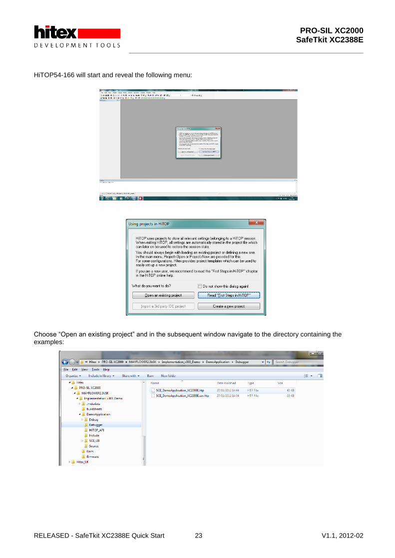
Figure 6 Location Of HiTOP54-166 Project Files
Start HiTOP54-166 from the Windows Start menu:
PRO-SIL XC2000 SafeTkit XC2388E
RELEASED - SafeTkit XC2388E Quick Start 23 V1.1, 2012-02
HiTOP54-166 will start and reveal the following menu: Choose “Open an existing project” and in the subsequent window navigate to the directory containing the examples:
PRO-SIL XC2000 SafeTkit XC2388E
RELEASED - SafeTkit XC2388E Quick Start 24 V1.1, 2012-02
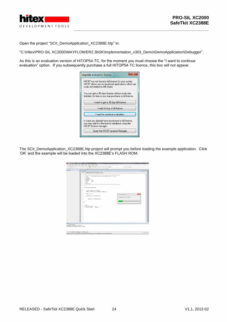
Open the project “SCII_DemoApplication_XC2388E.htp” in: “C:\Hitex\PRO-SIL XC2000\MAYFLOWER2.3bSK\Implementation_v303_Demo\DemoApplication\Debugger”. As this is an evaluation version of HiTOP54-TC, for the moment you must choose the “I want to continue evaluation” option. If you subsequently purchase a full HiTOP54-TC licence, this box will not appear. The SCII_DemoApplication_XC2388E.htp project will prompt you before loading the example application. Click ‟OK‟ and the example will be loaded into the XC2388E‟s FLASH ROM.

PRO-SIL XC2000 SafeTkit XC2388E
RELEASED - SafeTkit XC2388E Quick Start 25 V1.1, 2012-02
This operation will take a few seconds to complete. Finally, HiTOP will show the start of the program at the address 0xC00000.
The program is now ready to run.
PRO-SIL XC2000 SafeTkit XC2388E
RELEASED - SafeTkit XC2388E Quick Start 26 V1.1, 2012-02
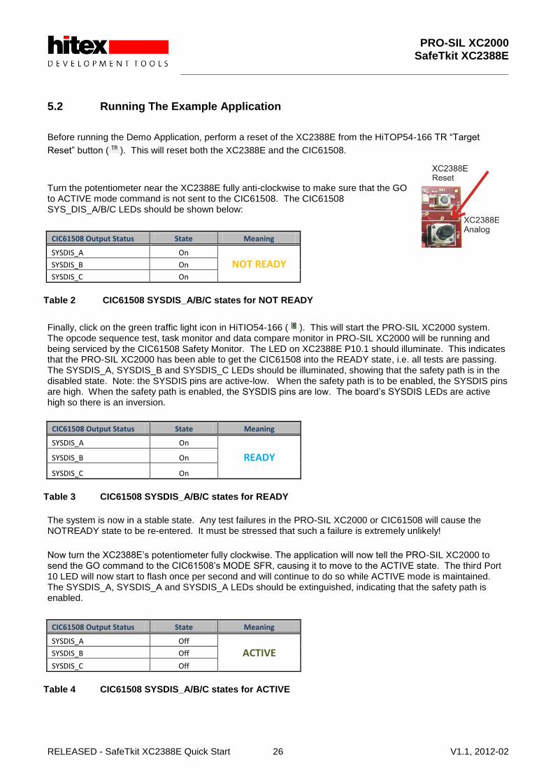
5.2 Running The Example Application
Before running the Demo Application, perform a reset of the XC2388E from the HiTOP54-166 TR “Target
Reset” button ( ). This will reset both the XC2388E and the CIC61508.
Turn the potentiometer near the XC2388E fully anti-clockwise to make sure that the GO to ACTIVE mode command is not sent to the CIC61508. The CIC61508 SYS_DIS_A/B/C LEDs should be shown below:
CIC61508 Output Status State Meaning
SYSDIS_A On
NOT READY SYSDIS_B On
SYSDIS_C On
Table 2 CIC61508 SYSDIS_A/B/C states for NOT READY
Finally, click on the green traffic light icon in HiTIO54-166 ( ). This will start the PRO-SIL XC2000 system. The opcode sequence test, task monitor and data compare monitor in PRO-SIL XC2000 will be running and being serviced by the CIC61508 Safety Monitor. The LED on XC2388E P10.1 should illuminate. This indicates that the PRO-SIL XC2000 has been able to get the CIC61508 into the READY state, i.e. all tests are passing. The SYSDIS_A, SYSDIS_B and SYSDIS_C LEDs should be illuminated, showing that the safety path is in the disabled state. Note: the SYSDIS pins are active-low. When the safety path is to be enabled, the SYSDIS pins are high. When the safety path is enabled, the SYSDIS pins are low. The board‟s SYSDIS LEDs are active high so there is an inversion.
CIC61508 Output Status State Meaning
SYSDIS_A On
READY SYSDIS_B On
SYSDIS_C On
Table 3 CIC61508 SYSDIS_A/B/C states for READY
The system is now in a stable state. Any test failures in the PRO-SIL XC2000 or CIC61508 will cause the NOTREADY state to be re-entered. It must be stressed that such a failure is extremely unlikely!
Now turn the XC2388E‟s potentiometer fully clockwise. The application will now tell the PRO-SIL XC2000 to send the GO command to the CIC61508‟s MODE SFR, causing it to move to the ACTIVE state. The third Port 10 LED will now start to flash once per second and will continue to do so while ACTIVE mode is maintained. The SYSDIS_A, SYSDIS_A and SYSDIS_A LEDs should be extinguished, indicating that the safety path is enabled.
CIC61508 Output Status State Meaning
SYSDIS_A Off
ACTIVE SYSDIS_B Off
SYSDIS_C Off
Table 4 CIC61508 SYSDIS_A/B/C states for ACTIVE

PRO-SIL XC2000 SafeTkit XC2388E
RELEASED - SafeTkit XC2388E Quick Start 27 V1.1, 2012-02
Turning the potentiometer anti-clockwise again will cause the STOP command to be sent to the CIC61508 and it will move to the DISABLED state. The SYSDIS_X LEDs should be illuminated showing that the safety path is disabled once again.
CIC61508 Output Status State Meaning
SYSDIS_A On
DISABLED SYSDIS_B On
SYSDIS_C On
Table 5 CIC61508 SYSDIS_A/B/C states for DISABLED
PRO-SIL XC2000 SafeTkit XC2388E
RELEASED - SafeTkit XC2388E Quick Start 28 V1.1, 2012-02
5.3 Monitoring The PRO-SIL XC2000 State
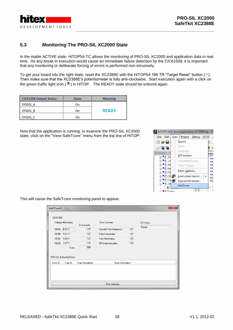
In the stable ACTIVE state, HiTOP54-TC allows the monitoring of PRO-SIL XC2000 and application data in real time. As any break in execution would cause an immediate failure detection by the CIC61508, it is important that any monitoring or deliberate forcing of errors is performed non-intrusively. To get your board into the right state, reset the XC2388E with the HiTOP54-166 TR “Target Reset” button ( ). Then make sure that the XC2388E‟s potentiometer is fully anti-clockwise. Start execution again with a click on
the green traffic light icon ( ) in HiTOP. The READY state should be entered again.
CIC61508 Output Status State Meaning
SYSDIS_A On
READY SYSDIS_B On
SYSDIS_C On
Now that the application is running, to examine the PRO-SIL XC2000 state, click on the “View-SafeTcore” menu from the top line of HiTOP: This will cause the SafeTcore monitoring panel to appear.

PRO-SIL XC2000 SafeTkit XC2388E
RELEASED - SafeTkit XC2388E Quick Start 29 V1.1, 2012-02
5.3.1 Understanding The SafeTcore Monitoring Window
5.3.1.1 Monitoring CIC61508 SFRs
The current contents of the most important CIC61508 SFRs are displayed in real time. These are the error counters for each CIC61508 monitor subsystem:
Opcode Sequence Test
Data Comparator
Task Sequence Monitor
Voltage Monitor In addition, the overall CIC61508 system state is shown i.e. NOTREADY, READY, ACTIVE, DISABLED etc. The voltage present on each of the 4 analog channels is shown:
SENA
SENB
SENC
SEND A full description of the CIC61508 SFRs can be found in the CIC61508 User Manual 1.0, section, 2.2.5. These SFRs are also visible via the PRO-SIL TestBench tool.

PRO-SIL XC2000 SafeTkit XC2388E
RELEASED - SafeTkit XC2388E Quick Start 30 V1.1, 2012-02
If you now move the XC2388E potentiometer fully clockwise, the CIC61508 will move to the ACTIVE state.
CIC61508 Output Status State Meaning
SYSDIS_A Off
ACTIVE SYSDIS_B On
SYSDIS_C On
The CIC State box in the SafeTcore window will now change from READY to “Active”.
PRO-SIL XC2000 SafeTkit XC2388E
RELEASED - SafeTkit XC2388E Quick Start 31 V1.1, 2012-02
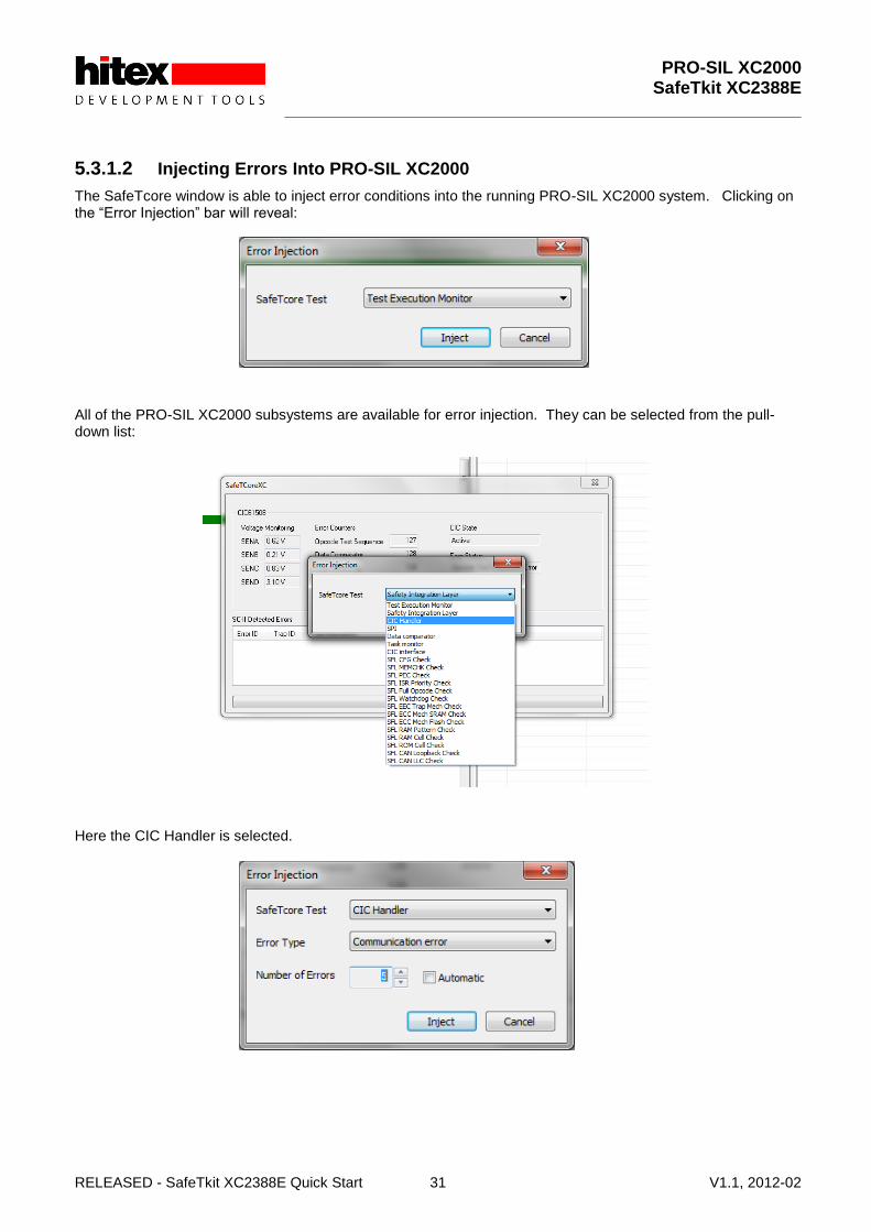
5.3.1.2 Injecting Errors Into PRO-SIL XC2000
The SafeTcore window is able to inject error conditions into the running PRO-SIL XC2000 system. Clicking on the “Error Injection” bar will reveal: All of the PRO-SIL XC2000 subsystems are available for error injection. They can be selected from the pull-down list: Here the CIC Handler is selected.

PRO-SIL XC2000 SafeTkit XC2388E
RELEASED - SafeTkit XC2388E Quick Start 32 V1.1, 2012-02
Here, the Error Injector has been told to inject five errors of type “Communication Error” into the CIC Handler. Five represents the error threshold set within PRO-SIL XC2000 for the reporting of errors – please refer to the PRO-SIL XC2000 user manual for more details on error thresholds. Clicking “Inject” will trigger HiTOP to insert the five communications error reports into the Test Execution Monitor (“TexM”) directly. This causes the PRO-SIL XC2000 to think that the SPI communications link to the CIC61508 has failed and so it immediately shuts the system down and the CIC61508 will enter the DISABLED state.
CIC61508 Output Status State Meaning
SYSDIS_A On
DISABLED SYSDIS_B On
SYSDIS_C On
The SafeTcore window now reports the error: Note: the CIC State is not updated to DISABLED as the SPI link appears to be faulty – hence the true CIC61508 state cannot be read back by HiTOP.

PRO-SIL XC2000 SafeTkit XC2388E
RELEASED - SafeTkit XC2388E Quick Start 33 V1.1, 2012-02
5.3.1.3 Monitoring Real Errors
If an error occurs during normal running of the PRO-SIL XC2000, this window will display the cause of the error.
To demonstrate this, stop HiTOP executing with the Red traffic light button ( ). Next, reset the XC2388E with the Target Reset button ( ). Start execution again and make sure that the CIC61508 enters the ACTIVE mode.
CIC61508 Output Status State Meaning
SYSDIS_A Off
ACTIVE SYSDIS_B On
SYSDIS_C On
To create a real error, carefully remove the red link from jumper JP401. Replace it immediately back into its original position!
Figure 7 Location Of JP401
This will cause the CIC61508 to lose its power supply and it will no longer respond to messages from the XC2388E and the PRO-SIL XC2000. This causes an immediate system shutdown. The SYSDIS LEDs will move to the DISABLED state and a “Communications Error” originating from the CIC handler will be reported by the SafeTcore window in HiTOP.
PRO-SIL XC2000 SafeTkit XC2388E
RELEASED - SafeTkit XC2388E Quick Start 34 V1.1, 2012-02
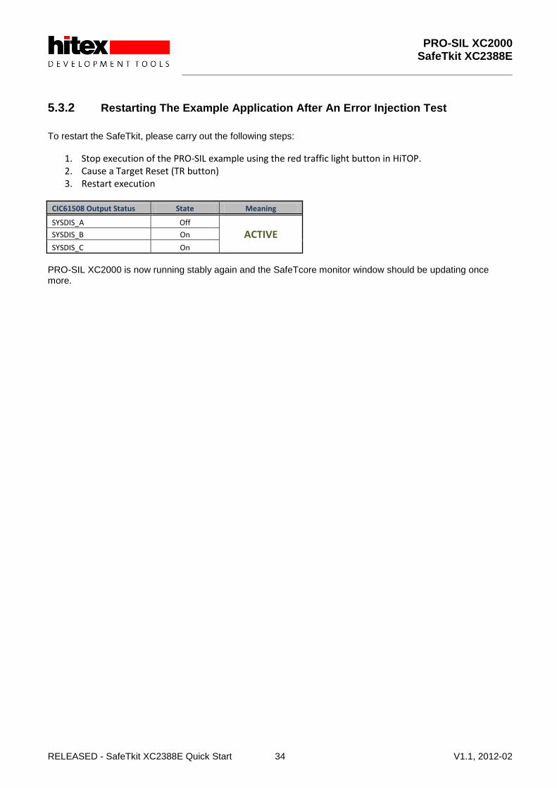
5.3.2 Restarting The Example Application After An Error Injection Test
To restart the SafeTkit, please carry out the following steps:
1. Stop execution of the PRO-SIL example using the red traffic light button in HiTOP. 2. Cause a Target Reset (TR button) 3. Restart execution
CIC61508 Output Status State Meaning
SYSDIS_A Off
ACTIVE SYSDIS_B On
SYSDIS_C On
PRO-SIL XC2000 is now running stably again and the SafeTcore monitor window should be updating once more.

PRO-SIL XC2000 SafeTkit XC2388E
RELEASED - SafeTkit XC2388E Quick Start 35 V1.1, 2012-02
6 Configuring And Monitoring The CIC61508
The PRO-SIL XC2000 TestBench is a special GUI-based tool that allows the CIC61508 to be tested and configured and is part of the TARDISS family of CIC61508/PRO_SIL support tools. It relies on a special driver running on the XC2388E to allow it to access the CIC61508‟s SPI interface from a COM port on a PC. The driver manages the flow of data between the XC2388E‟s USIC asynchronous serial (ASC) and SPI interfaces. The ASC interface is connected to an FTDI USB to serial converter chip. The version supplied with the SafeTkit is a specially adapted version of the full PRO-SIL TestBench toolkit. PRO-SIL TestBench functions include:
1. Simulation of the PRO-SIL XC2000 opcode sequence test, using the opcode test table stored in the CIC61508 DFLASH.
2. Simulation of the task monitor and data compare, using data tables stored in the CIC61508 DFLASH. 3. Live update of CIC61508 SFRs 4. Editing of SFR values 5. Reading of the DFLASH calibration data 6. Editing of DFLASH data such as safety path pins states, voltage monitor thresholds etc. 7. Programming of revised calibration data into the DFLASH 8. Importing DFLASH data from standard CIC61508 Build Sheet .XLS files 9. Export of DFLASH data to binary files, HEX files or compilable C-const arrays.
In the SafeTkit, the PRO-SIL TestBench driver has been included into the example application. By loading, starting the PRO-SIL TestBench and clicking connect, the driver will take control of the application and allow the GUI to take over. The CIC61508 SFRs can then be inspected, or changes made to the DFLASH calibration data. When the changes have been made, the PRO-SIL demonstration application can be re-loaded into the board and the effect of the changes assessed.

PRO-SIL XC2000 SafeTkit XC2388E
RELEASED - SafeTkit XC2388E Quick Start 36 V1.1, 2012-02
6.1 Loading The PRO-SIL TestBench Driver Into The SafeTkit
To make use of the TestBench, a special driver program must be loaded into the SafeTkit board. This is done by loading a new project into HiTOP54-TC. To do this, the current Demo Application project must be closed and a new project opened. To do this, click on Project-Close: Then Open the project “PRO-SIL TestBenchLoader.htp”. The driver is now programmed into the SafeTkit.

PRO-SIL XC2000 SafeTkit XC2388E
RELEASED - SafeTkit XC2388E Quick Start 37 V1.1, 2012-02
Start the driver by clicking on the green traffic light icon( ) in HiTOP, as before. The PRO-SIL TestBench GUI on the PC can now be started.
6.2 Reloading The Demo Application Project
When you have finished using the PRO-SIL TestBench, to reload the Demo Application the HiTOP project “SCII_DemoApplication_XC2388E.htp” must be loaded. Close the current HiTOP project and then Open the Demo Application project, as shown below.
Figure 8 Reloading The Demo Application Project

PRO-SIL XC2000 SafeTkit XC2388E
RELEASED - SafeTkit XC2388E Quick Start 38 V1.1, 2012-02
6.3 Starting The PRO-SIL TestBench
It is assumed that the SafeTkit is powered up and that the PRO-SIL TestBench driver has been loaded. Start TestBench from the Windows start menu. The first time the TestBench starts up you will have to carry out three special steps: (i) In the Configuration File box, the name of the configuration file for the CIC61508 needs to be entered. (ii) The COM port to which the SafeTkit‟s USB port has enumerated needs to be entered. (iii) The analog voltage reference value of 3.3V must be entered to suit the SafeTkit board. The CIC61508 configuration file is located in: C:\Program Files (x86)\PRO-SIL SafeTkit Test Bench\data\MILInfoTable.cfg Click on the file icon and navigate to this file and select it. Note: If you find in subsequent TestBench sessions that this file has not been remembered, it probably suggests that you did not have Administrator rights when you installed the GUI originally. To find the COM port used by the SafeTkit, click on Autodetect and after a few seconds the COM port number will appear in the Port box. The TestBench is now ready for use.

PRO-SIL XC2000 SafeTkit XC2388E
RELEASED - SafeTkit XC2388E Quick Start 39 V1.1, 2012-02
6.4 Connecting To The SafeTkit Board
Make sure that the TestBench driver in the board is running and that the CIC61508 is in ACTIVE mode.
CIC61508 Output Status State Meaning
SYSDIS_A Off
ACTIVE SYSDIS_B Off
SYSDIS_C Off
Click‟ Connect‟ in the GUI and the TestBench will take control of the SafeTkit via the XC2388E‟s USIC ASC port. The „Connect‟ button will change to‟ Initialising…‟ It will then enter Secure SPI mode (See CIC61508 User Manual section 2.8) and read the contents of the DFLASH area, putting them in its internal DFLASH edit buffer. This process can take around 20-30 seconds and finishes with a device reset.
Figure 9 Initialization Of The Internal DFLASH Edit Buffer
PRO-SIL XC2000 SafeTkit XC2388E
RELEASED - SafeTkit XC2388E Quick Start 40 V1.1, 2012-02
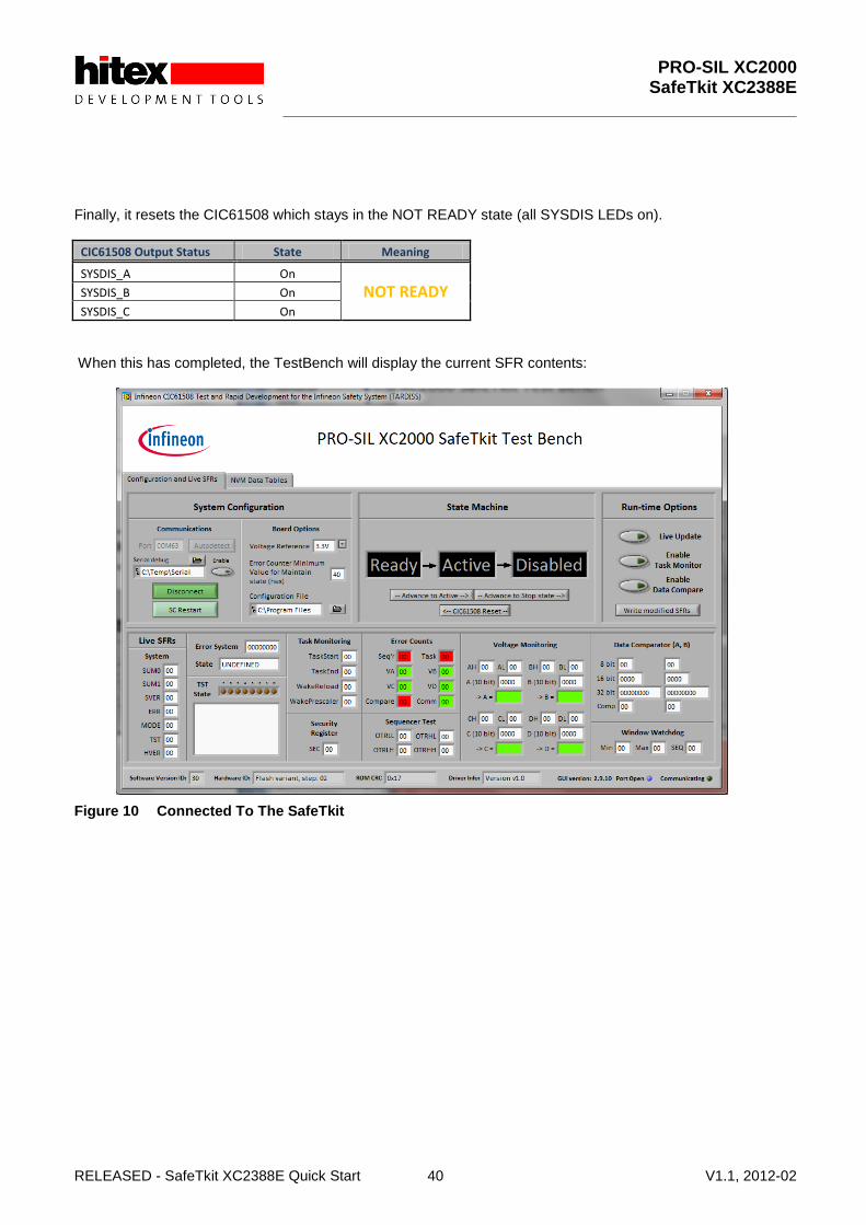
Finally, it resets the CIC61508 which stays in the NOT READY state (all SYSDIS LEDs on).
CIC61508 Output Status State Meaning
SYSDIS_A On
NOT READY SYSDIS_B On
SYSDIS_C On
When this has completed, the TestBench will display the current SFR contents:
Figure 10 Connected To The SafeTkit
PRO-SIL XC2000 SafeTkit XC2388E
RELEASED - SafeTkit XC2388E Quick Start 41 V1.1, 2012-02
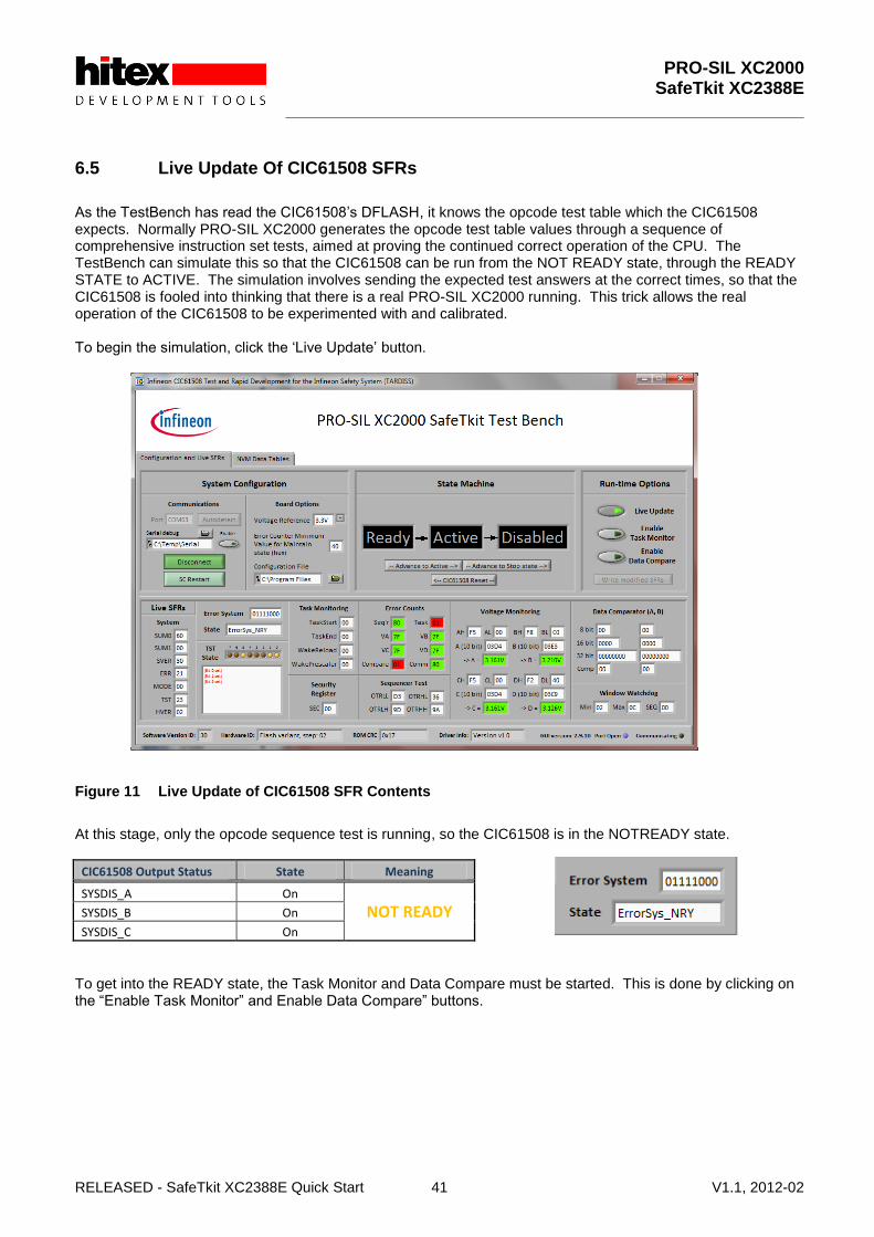
6.5 Live Update Of CIC61508 SFRs
As the TestBench has read the CIC61508‟s DFLASH, it knows the opcode test table which the CIC61508 expects. Normally PRO-SIL XC2000 generates the opcode test table values through a sequence of comprehensive instruction set tests, aimed at proving the continued correct operation of the CPU. The TestBench can simulate this so that the CIC61508 can be run from the NOT READY state, through the READY STATE to ACTIVE. The simulation involves sending the expected test answers at the correct times, so that the CIC61508 is fooled into thinking that there is a real PRO-SIL XC2000 running. This trick allows the real operation of the CIC61508 to be experimented with and calibrated. To begin the simulation, click the „Live Update‟ button.
Figure 11 Live Update of CIC61508 SFR Contents
At this stage, only the opcode sequence test is running, so the CIC61508 is in the NOTREADY state.
CIC61508 Output Status State Meaning
SYSDIS_A On
NOT READY SYSDIS_B On
SYSDIS_C On
To get into the READY state, the Task Monitor and Data Compare must be started. This is done by clicking on the “Enable Task Monitor” and Enable Data Compare” buttons.

PRO-SIL XC2000 SafeTkit XC2388E
RELEASED - SafeTkit XC2388E Quick Start 42 V1.1, 2012-02
After a few seconds, the CIC61508 state will be displayed on the GUI as READY.
CIC61508 Output Status State Meaning
SYSDIS_A On
READY SYSDIS_B On
SYSDIS_C On
Table 6 CIC61508 SYSDIS_A/B/C states for READY
As the Opcode Sequence Test, Task Monitor and Data Compare are all now running and the voltage monitors are disabled (as delivered), the CIC61508 will enter the READY state.

PRO-SIL XC2000 SafeTkit XC2388E
RELEASED - SafeTkit XC2388E Quick Start 43 V1.1, 2012-02
6.6 Entering The ACTIVE State
Once the READY state has been reached, the ACTIVE state can be enabled. This is done by clicking on “Advance To Active” to write the GO command to the CIC61508 MODE SFR. Note: this is normally done by the PRO-SIL XC2000 during initialization.
This sends the command ESTM_GO_REQ to the CIC61508‟s MODE SFR. The ACTIVE state causes a change in the SYSDIS_X LEDs:
CIC61508 Output Status State Meaning
SYSDIS_A Off
ACTIVE SYSDIS_B Off
SYSDIS_C Off
From now on any disturbance to the opcode test will cause the CIC to drop out of the ACTIVE state and move to the TRIP1, TRIP2, TRIP3 and finally the DISABLED state.
6.7 Moving To The DISABLED State
To move to the DISABLED state, send the STOP command to the CIC61508 MODE SFR. Clicking on the “Advance To Stop state” will do this. The CIC61508 will then move to the DISABLED state.
CIC61508 Output Status State Meaning
SYSDIS_A On
DISABLED SYSDIS_B On
SYSDIS_C On

PRO-SIL XC2000 SafeTkit XC2388E
RELEASED - SafeTkit XC2388E Quick Start 44 V1.1, 2012-02
6.8 Restarting After DISABLED Mode
Once in the DISABLED state, only a RESET will allow the CIC61508 to recover. This is done either by pressing the CIC61508 reset button on the SafeTkit, or by clicking the “CIC61508 Reset” button in the GUI. If the live update button, task monitor and data compare are still enabled, the CIC61508 will go straight to the READY state:
CIC61508 Output Status State Meaning
SYSDIS_A On
READY SYSDIS_B On
SYSDIS_C On
However, if you disable the Live Update button, clicking the CIC61508 Reset button will cause the CIC61508 to reset but then go to the NOT READY state (this is the state expected when the PRO-SIL XC2000 restarts).
CIC61508 Output Status State Meaning
SYSDIS_A On
NOT READY SYSDIS_B On
SYSDIS_C On
This is because the simulated opcode test, task monitor and data compare only run when the live update function is enabled. Hence the NOT READY state is only maintained until the opcode test error counter has reached or exceeded 0x40 (CIC61508 User Manual section 2.2.1).

PRO-SIL XC2000 SafeTkit XC2388E
RELEASED - SafeTkit XC2388E Quick Start 45 V1.1, 2012-02
6.9 Editing The CIC61508 Calibration Data In DFLASH
With the default configuration in the CIC61508 DFLASH, the four voltage monitors are disabled. This means that the potentiometer settings are not taken into account when the CIC61508 determines whether it can enter the READY state – just having a successful opcode test sequence, task sequence and data compares from the PRO-SIL XC2000 are sufficient.
Figure 12 The CIC61508 Voltage Monitor Potentiometers
However in a real system, the analog channels would be connected to critical voltages in the main system, such as the supplies to the XC2388E, for example. The SafeTkit XC2388E supports this, but for this test the potentiometers must be used as the voltage sources. In the next session we will enable the voltage monitor A (SENA) channel to see what effect it has on overall system behaviour.

PRO-SIL XC2000 SafeTkit XC2388E
RELEASED - SafeTkit XC2388E Quick Start 46 V1.1, 2012-02
6.10 The PRO-SIL TestBench DFLASH Editor
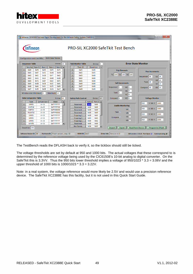
The TestBench allows you to edit the data in DFLASH via the “NVM Data Tables” editor tab – click on this now. In the following text, the terms “DFLASH data”, “calibration data set” and “NVM tables” all refer to the data displayed in this window.
Figure 13 The NVM Data Editing Tab
The following functions are available:
1. Read the DFLASH contents into the TestBench’s local editing area 2. Read a new DFLASH calibration from the reference CIC61508 spreadsheet (e.g.
CIC61508_BuildSheet_VANIA30_SafeTkit.xls). 3. Change values of any item in this area. 4. Edit the data tables in a user-friendly manner. 5. Write the new DFLASH data into the CIC61508 DFLASH. 6. Export the DFLASH editing area’s contents to a .XLS spreadsheet, a .BIN binary dump file, a HEX file or
a .C text file, containing the DFLASH contents as a compilable C const array. After first connecting to the CIC61508, the current DFLASH contents are uploaded from the device and displayed here. Note that the CIC61508 Task Monitor and Data Compare functions are enabled. The Opcode Sequence Test Table panel shows the table of expected answers to be returned by the PRO-SIL XC2000 in response to predefined “questions”. The answers are calculated by the PRO-SIL XC2000, based on specially designed instruction set sequences that will prove the correct operation of the XC2388E CPU. The table does not usually need to be modified, as this would require changes in the PRO-SIL XC2000 which are outside the scope of the SafeTkit.
PRO-SIL XC2000 SafeTkit XC2388E
RELEASED - SafeTkit XC2388E Quick Start 47 V1.1, 2012-02
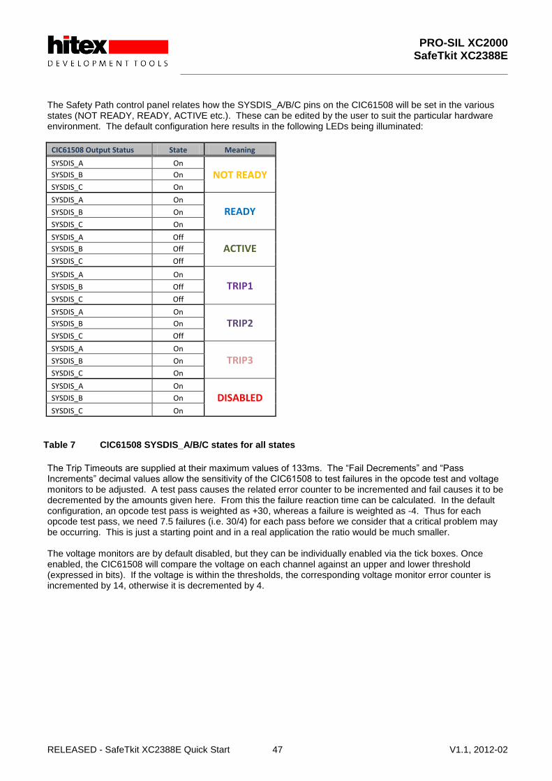
The Safety Path control panel relates how the SYSDIS_A/B/C pins on the CIC61508 will be set in the various states (NOT READY, READY, ACTIVE etc.). These can be edited by the user to suit the particular hardware environment. The default configuration here results in the following LEDs being illuminated:
CIC61508 Output Status State Meaning
SYSDIS_A On
NOT READY SYSDIS_B On
SYSDIS_C On
SYSDIS_A On
READY SYSDIS_B On
SYSDIS_C On
SYSDIS_A Off
ACTIVE SYSDIS_B Off
SYSDIS_C Off
SYSDIS_A On
TRIP1 SYSDIS_B Off
SYSDIS_C Off
SYSDIS_A On
TRIP2 SYSDIS_B On
SYSDIS_C Off
SYSDIS_A On
TRIP3 SYSDIS_B On
SYSDIS_C On
SYSDIS_A On
DISABLED SYSDIS_B On
SYSDIS_C On
Table 7 CIC61508 SYSDIS_A/B/C states for all states
The Trip Timeouts are supplied at their maximum values of 133ms. The “Fail Decrements” and “Pass Increments” decimal values allow the sensitivity of the CIC61508 to test failures in the opcode test and voltage monitors to be adjusted. A test pass causes the related error counter to be incremented and fail causes it to be decremented by the amounts given here. From this the failure reaction time can be calculated. In the default configuration, an opcode test pass is weighted as +30, whereas a failure is weighted as -4. Thus for each opcode test pass, we need 7.5 failures (i.e. 30/4) for each pass before we consider that a critical problem may be occurring. This is just a starting point and in a real application the ratio would be much smaller. The voltage monitors are by default disabled, but they can be individually enabled via the tick boxes. Once enabled, the CIC61508 will compare the voltage on each channel against an upper and lower threshold (expressed in bits). If the voltage is within the thresholds, the corresponding voltage monitor error counter is incremented by 14, otherwise it is decremented by 4.

PRO-SIL XC2000 SafeTkit XC2388E
RELEASED - SafeTkit XC2388E Quick Start 48 V1.1, 2012-02
6.11 Enabling Voltage Monitor Channel A
Now we will enable the voltage monitor channel A, so that the SENA potentiometer will have an effect. Do this by clicking on the VA tick box in the Enabling Monitoring panel.
Figure 14 Enabling Voltage Monitor Channel A
The “Program To DFLASH” button will now start to flash in yellow. Click this button and the modified calibration data will be blown into the CIC61508‟s DFLASH.
PRO-SIL XC2000 SafeTkit XC2388E
RELEASED - SafeTkit XC2388E Quick Start 49 V1.1, 2012-02
The TestBench reads the DFLASH back to verify it, so the tickbox should still be ticked. The voltage thresholds are set by default at 950 and 1000 bits. The actual voltages that these correspond to is determined by the reference voltage being used by the CIC61508‟s 10-bit analog to digital converter. On the SafeTkit this is 3.3VV. Thus the 950 bits lower threshold implies a voltage of 950/1023 * 3.3 = 3.06V and the upper threshold of 1000 bits is 1000/1023 * 3.3 = 3.22V. Note: in a real system, the voltage reference would more likely be 2.5V and would use a precision reference device. The SafeTkit XC2388E has this facility, but it is not used in this Quick Start Guide.

PRO-SIL XC2000 SafeTkit XC2388E
RELEASED - SafeTkit XC2388E Quick Start 50 V1.1, 2012-02
6.11.1 Testing The New Configuration In The TestBench
Return to the “Configuration and Live SFRs tab” and make sure that the Voltage Reference box is set to 3.3V using the drop down menu. Now click the Live Updates button and you should see that the voltages being displayed are now referenced to 3.3V. Depending on how your board has been shipped, the SENA potentiometer may not be correctly set, so the display may show a red background on channel A:

PRO-SIL XC2000 SafeTkit XC2388E
RELEASED - SafeTkit XC2388E Quick Start 51 V1.1, 2012-02
If your board shows channel A as green, please move the SENA potentiometer slightly, so that the voltage goes out of range and the VA Error Count is now “01” against a red background. You should see that the overall CIC61508 state is NOT READY.
CIC61508 Output Status State Meaning
SYSDIS_A On
NOT READY SYSDIS_B On
SYSDIS_C On
Now move the SENA potentiometer slowly, so that the voltage moves between the lower and upper thresholds. The VA error count and the actual voltage readings should become green. The VA error count will then rise to 0x7F showing that the tests are passing.

PRO-SIL XC2000 SafeTkit XC2388E
RELEASED - SafeTkit XC2388E Quick Start 52 V1.1, 2012-02
Enable the Task Monitor And Data Compare tests and the CIC61508 state should now move to READY The final step is to move the CIC61508 to the ACTIVE mode using the “Advance to Active” button. You should see the SYSDIS_X LEDs change as per:
CIC61508 Output Status State Meaning
SYSDIS_A Off
ACTIVE SYSDIS_B On
SYSDIS_C On
This is the state that the PRO-SIL XC2000 reaches during its initialization procedure, so that by the time the StartupHook() function exits, the CIC61508 is in a stable state with the Safety Path enabled. /* Call SafeTcore start-up hook */
Sil_StartupHook();
PRO-SIL XC2000 SafeTkit XC2388E
RELEASED - SafeTkit XC2388E Quick Start 53 V1.1, 2012-02
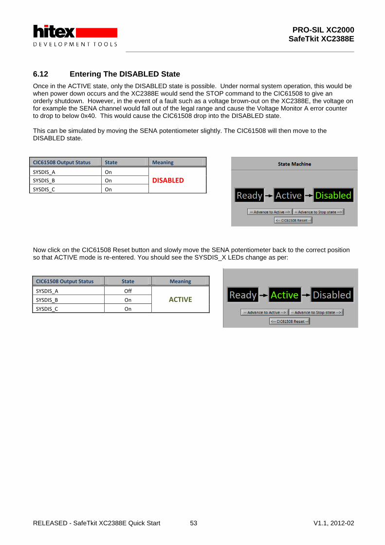
6.12 Entering The DISABLED State
Once in the ACTIVE state, only the DISABLED state is possible. Under normal system operation, this would be when power down occurs and the XC2388E would send the STOP command to the CIC61508 to give an orderly shutdown. However, in the event of a fault such as a voltage brown-out on the XC2388E, the voltage on for example the SENA channel would fall out of the legal range and cause the Voltage Monitor A error counter to drop to below 0x40. This would cause the CIC61508 drop into the DISABLED state. This can be simulated by moving the SENA potentiometer slightly. The CIC61508 will then move to the DISABLED state.
Now click on the CIC61508 Reset button and slowly move the SENA potentiometer back to the correct position so that ACTIVE mode is re-entered. You should see the SYSDIS_X LEDs change as per:
CIC61508 Output Status State Meaning
SYSDIS_A Off
ACTIVE SYSDIS_B On
SYSDIS_C On
CIC61508 Output Status State Meaning
SYSDIS_A On
DISABLED SYSDIS_B On
SYSDIS_C On
PRO-SIL XC2000 SafeTkit XC2388E
RELEASED - SafeTkit XC2388E Quick Start 54 V1.1, 2012-02
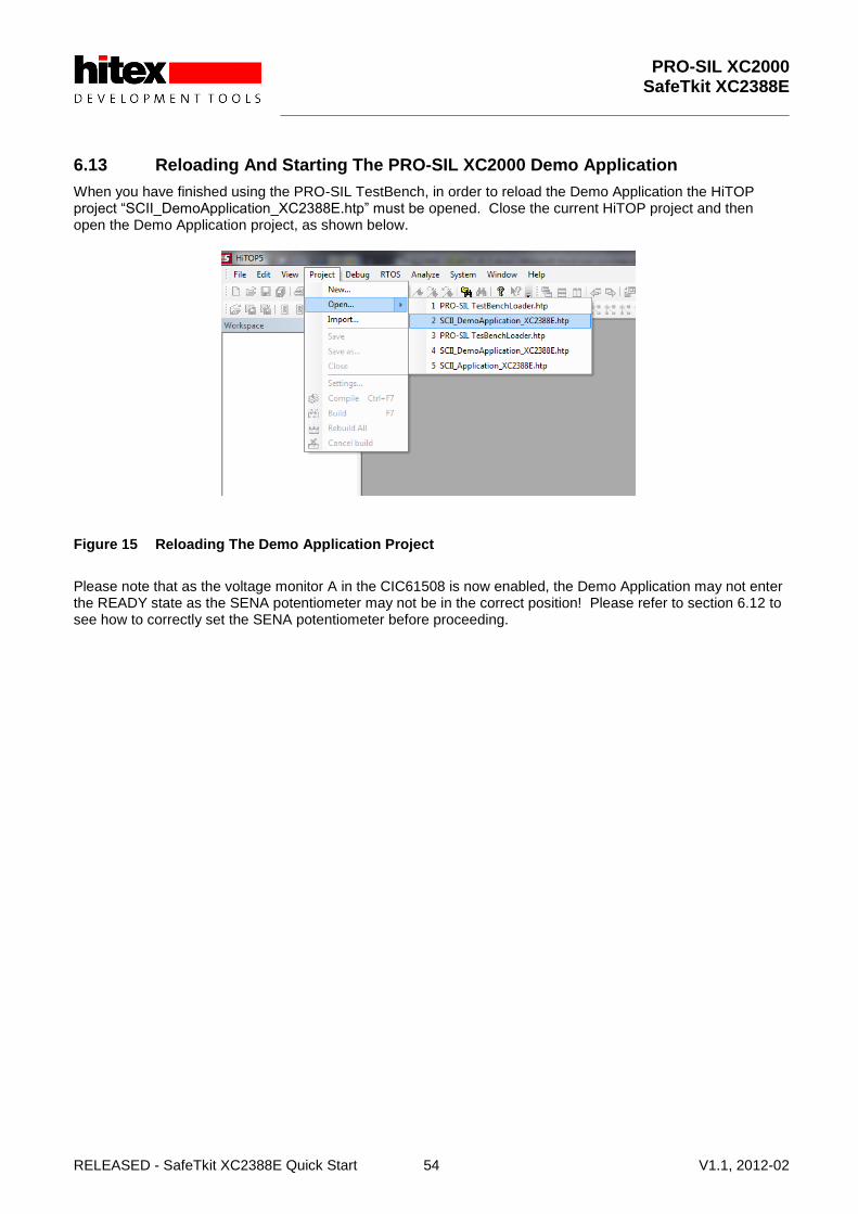
6.13 Reloading And Starting The PRO-SIL XC2000 Demo Application
When you have finished using the PRO-SIL TestBench, in order to reload the Demo Application the HiTOP project “SCII_DemoApplication_XC2388E.htp” must be opened. Close the current HiTOP project and then open the Demo Application project, as shown below.
Figure 15 Reloading The Demo Application Project
Please note that as the voltage monitor A in the CIC61508 is now enabled, the Demo Application may not enter the READY state as the SENA potentiometer may not be in the correct position! Please refer to section 6.12 to see how to correctly set the SENA potentiometer before proceeding.

PRO-SIL XC2000 SafeTkit XC2388E
RELEASED - SafeTkit XC2388E Quick Start 55 V1.1, 2012-02
6.13.1 Testing The New CIC61508 Configuration With The PRO-SIL XC2000 Application
6.13.1.1 Restart PRO-SIL XC2000 With SENA In The Correct Position
It is assumed that the Demo Application has been reloaded into the SafeTkit. We can now restart the PRO-SIL XC2000 application. HiTOP54-166 should appear as shown below.
Before running the Demo Application, perform a reset of the XC2388E from the TR “Target Reset” button ( ). This will reset both the XC2388E and the CIC61508. The yellow LED 3 should flash approximately once per second and the CIC61508‟s SYSDIS_A, SYSDIS_B and SYSDIS_C LED should be off. This indicates that the board is in a running condition and that the CIC61508 has reached the ACTIVE mode.
CIC61508 Output Status State Meaning
SYSDIS_A Off
ACTIVE SYSDIS_B Off
SYSDIS_C Off
We are now in a position to really see how the PRO-SIL safety system functions. The SENA potentiometer should still be in the correct position so that the voltage read on SENA is within the upper and lower thresholds, here 950 bits and 1000 bits. If you now move the SENA potentiometer slightly, the voltage will move outside of the range and the CIC61508 will start to register test failures. Eventually the VA error counter will drop below 0x40 (MAINTAIN threshold) and the CIC61508 state will drop through the TRIP1/2/3 states to DISABLED. Try this whilst looking at the SYSDIS. LEDs.

PRO-SIL XC2000 SafeTkit XC2388E
RELEASED - SafeTkit XC2388E Quick Start 56 V1.1, 2012-02
They will end up in the DISABLED state, but you may be able to detect them sequencing through the TRIP states on the way.
CIC61508 Output Status State Meaning
SYSDIS_A On
DISABLED SYSDIS_B On
SYSDIS_C On
The yellow LEDs will stop flashing and all 4 will be on, showing that the PRO-SIL XC2000 application has shut down.
6.13.1.2 Restart PRO-SIL XC2000 With SENA In An Incorrect Position
If PRO-SIL XC2000 tries to start from reset with SENA at the wrong voltage, it will never reach the READY or ACTIVE states, remaining in the NOTREADY condition.
CIC61508 Output Status State Meaning
SYSDIS_A Off
NOT READY SYSDIS_B Off
SYSDIS_C On
This simulates a power-up fault where perhaps the supply voltage for a critical element is out of limits and so the PRO-SIL system prevents the system from starting up in a potentially dangerous or unstable state.
6.13.2 Restoring The SafeTkit To A Running Condition
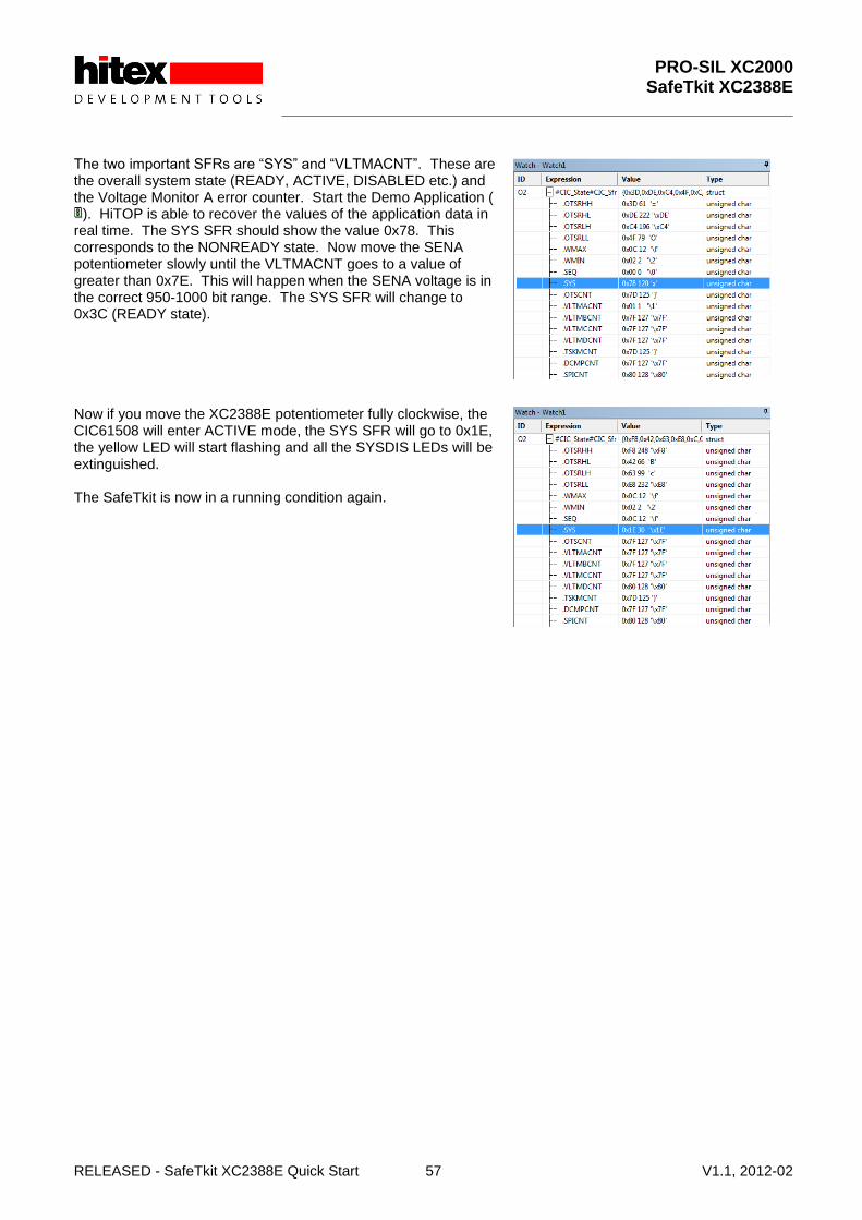
It is not a good idea to leave the SafeTKit in a state where it will not power-up and run in the ACTIVE mode! To get it working again, we will need to check the state of the Voltage Monitor A error counter. Make sure that the XC2388E potentiometer (below the LCD panel) is fully anti-clockwise. Checking the state of the error counters is done using the Watch window in HiTOP54-166. Click on the Watch1 tab to reveal a structure within PRO-SIL XC2000 that contains an image of the current CIC61508 SFRs called “CIC_Sfr”. Click on the „+‟ to the left of “#CIC_State#CIC_Sfr” to expose the structure elements.
PRO-SIL XC2000 SafeTkit XC2388E
RELEASED - SafeTkit XC2388E Quick Start 57 V1.1, 2012-02
The two important SFRs are “SYS” and “VLTMACNT”. These are the overall system state (READY, ACTIVE, DISABLED etc.) and the Voltage Monitor A error counter. Start the Demo Application (
). HiTOP is able to recover the values of the application data in real time. The SYS SFR should show the value 0x78. This corresponds to the NONREADY state. Now move the SENA potentiometer slowly until the VLTMACNT goes to a value of greater than 0x7E. This will happen when the SENA voltage is in the correct 950-1000 bit range. The SYS SFR will change to 0x3C (READY state). Now if you move the XC2388E potentiometer fully clockwise, the CIC61508 will enter ACTIVE mode, the SYS SFR will go to 0x1E, the yellow LED will start flashing and all the SYSDIS LEDs will be extinguished. The SafeTkit is now in a running condition again.

PRO-SIL XC2000 SafeTkit XC2388E
RELEASED - SafeTkit XC2388E Quick Start 58 V1.1, 2012-02
6.14 Conclusion
That completes the Quick Start Introduction. The next few sections cover more advanced information on the topics covered so far.

PRO-SIL XC2000 SafeTkit XC2388E
RELEASED - SafeTkit XC2388E Quick Start 59 V1.1, 2012-02
7 PRO-SIL XC2000 Example Applications
7.1 Adapting The PRO-SIL XC2000 For The SafeTkit XC2388E
The PRO-SIL XC2000 has been adapted to make it more suitable for use in a starter kit environment. The major adaptations are listed below. All the elements of the PRO-SIL XC2000 necessary to build an application are located in the SCII_LIB subdirectory inside the Demo Application directory. The main PRO-SIL XC2000 system consists of thirty „C‟ source files. These have been compiled into an object library “SCII_Source.lib” during the kit preparation. This is located in the SCII_LIB\Lib directory in the Demo Application. The linker accesses this library in this location to resolve any PRO-SIL external symbols. The Application call-back functions are in Applcbk.c. This is located in SCII_LIB\Source. It has been adapted from the standard delivery to record the details of any errors in a global structure. All the include files for PRO-SIL XC2000 are collected together and placed in SCII_LIB\lib\Include. This allows the Demo Application to find all the necessary header files without having access to the normal PRO-SIL XC2000 directory structure. The Demo Application is essentially fixed and no PRO-SIL XC2000 settings can be changed.
7.2 Advanced Example Application
The Standard Application allows the Task Execution Monitor configuration to be altered and tests to be enabled or disabled in the startup procedure. This application is recommended for use as the basis of customers‟ own developments, as the transfer to the full source code version of PRO-SIL XC2000 is easy. It is not included in the Tasking Eclipse workspace but it can be found in: C:\Hitex\PRO-SIL XC2000\MAYFLOWER2.3bSK\Implementation_v303_Demo\Standard Application In this application, the PRO-SIL XC2000 again exists as a library, but the PRO-SIL source files TexM.c, Sil.c, Sil_Cfg.c have been placed in the SCI_LIB\Source directory to allow local changes to be made. Sil_Cfg.c contains the peripheral SFR configuration check structures that are used in the startup and shutdown hooks. The upper and lower error thresholds for each monitor, as well the enabling or disabling of tests, is performed via the SCII_cfg.h file located in SCII_LIB\Include. The object files created by compiling these from within the applications replace the standard ones in the SCII_Source.lib. The Standard Application can be configured using the guidance contained in the full PRO-SIL XC2000 User Manual in Chapter “5 Configuring PRO-SIL XC2000: Generic”. Please note that the evaluation tools and software supplied in the SafeTkit have limitations that allow prototype application development, but preclude the creation of commercial applications. These restrictions can be overcome by purchasing the full versions from Hitex.
PRO-SIL XC2000 SafeTkit XC2388E
RELEASED - SafeTkit XC2388E Quick Start 60 V1.1, 2012-02
7.3 SafeTkit Default PRO-SIL XC2000 Configurations
The settings contained in the default SCII_Cfg.H for use on the SafeTkit XC2388E are: Lower Error Count Thresholds: 10 Upper Error Count Thresholds: 5 XC2388E clock: 80MHz System period: 6ms System tick time: 600us All tests enabled in startup and shutdown hooks RAM Cell test and Peripheral Configuration test enabled for cyclic operation For detailed information on the operation and configuration of the PRO-SIL XC2000 SafeTkit version, please refer to the PRO-SIL XC2000 User Manual.

PRO-SIL XC2000 SafeTkit XC2388E
RELEASED - SafeTkit XC2388E Quick Start 61 V1.1, 2012-02
8 Further Information
This document provides a brief introduction to the SafeTkit and the PRO-SIL safety system. You can find out more in the following documents:
8.1 Information On The Application Of PRO-SIL XC2000 TO ISO26262
4227.XC2300_SafetyConcept_IFX.pdf
8.2 Information On Importing And Exporting CIC61508 Calibration Data Sets
PRO-SIL TestBench User Manual
8.3 Advanced CIC61508 Operation
CIC61508 User Manual v1.0.pdf
8.4 Detailed Operation And Configuration Of The PRO-SIL XC2000 Safety Driver
PRO-SIL XC2000 UM v1.8.pdf

PRO-SIL XC2000 SafeTkit XC2388E
RELEASED - SafeTkit XC2388E Quick Start 62 V1.1, 2012-02
9 Appendix A: Programming The CIC61508 Firmware
9.1 Installing The CIC61508 Firmware
The CIC61508 firmware is programmed via a dedicated JTAG connector. A USB-JTAG interface such as the Hitex Tantino or MiniWiggler must be attached to this. A programming application is then required. The Infineon FLOAD tool is recommended and this is supplied in: C:\Hitex\PRO-SIL XC2000\MAYFLOWER2.3bSK\Implementation_v303_Demo\firmware\FLOADsetup_v4.7.exe This must be installed using this setup .EXE file. The CIC61508 firmware is contained in: C:\Hitex\PRO-SIL XC2000\MAYFLOWER2.3bSK\Implementation_v303_Demo \firmware\cic61508_XC2388ESafeTkit.hex

w w w . h i t e x . c o m
Published by Hitex (U.K.) Limited. 4231.XC2388E, V1.1