Embed Size (px)
Citation preview

Pro SeriesINSTRUCTIONAL MANUALDK1100 Electric and Pneumatic Models / DK3100
DK1100 FEDK1100 FP
DK1100 TP
DK3100
RECOMMENDED AIR PRESSURES:Electric Models: 90 psiPneumatic Models: 120 psi Version 20051001
K-SERIESThe Blue Mark of Quality.

Congratulations on choosing a Kreg Pro Series Pocket Hole Machine!
Be sure to read the instructions and the safety warnings completely before using this tool.
Table of Contents
TABLE OF CONTENTS 1
SAFETY INSTRUCTIONS 2-3
PARTS DIAGRAMS 4-6
DK1100 FE (Electric Model) 7-9
Changing Drill Bits 7
Adjusting the Drill Bit Depth Stop 7
Adjusting Fence Setting 8
Adjusting Clamping Cylinder Height 8
Feed Rate Flow Control 9
Belt Tension 9
DK1100 TP / FP (Pnuematic Models) 10-12
Changing Drill Bits 10
Adjusting the Drill Bit Stop 10
Adjusting the Fence Setting 11
Adjusting the Clamping Cylinder Height 11
Feed Rate Flow Control 12
Air System Prefilter 12
DK3100 13-15
Changing Drill Bits 13
Adjusting the Drill Bit Stop 13
Adjusting the Fence Setting 14
Adjusting the Clamping Cylinder Height 14
Feed Rate Flow Control 15
Air System Prefilter 15
Belt Tension 15
Warranty 16
Table of Contents 1

Safety Guidelines 2
- Woodworking machines are dangerous and can cause personal injury if not used properly.- Read safety instructions and operating instructions for your machine completely before using products. Using this system before understanding its safe and proper use could result in serious injury to the operator.- Warning: Failure to follow these rules may result in serious personal injury.- For your own safety, read instruction manual before operating the tool. Learn the tools application and limitations as well as the specific hazards peculiar to it.- Keep all guards and safety devices in proper place while using these products.- Always wear safety glasses.- Keep hands well away from the pneumatic clamp and rotating bit when operating machine.- Avoid awkward hand positions, where a sudden slip could cause contact with rotating bit. Never reach under the pneumatic clamp pad with either hand to hold down the workpiece.
Beware of kickbacks; they can cause serious injury. A kickback occurs when the workpiece binds up whilebeing drilled, causing it to twist, jump, or become airborne.
To avoid kickbacks:- Always use sharp drill bits.- Keep machine in proper alignment and good working condition.- Never perform any “free hand” drilling. Work must always be held securely against the table and fence.- Always support longer boards when drilling.
- Kreg components are fully guaranteed for one year from date of purchase.- Kreg will replace or repair, at no charge to the customer, any product that fails within the warranty period.- Kreg will service Kreg components beyond the warranty period at a reasonable cost to customer.- Any neglect, misuse or usage of the Tools in a fashion not recommended by Kreg will void all warranties.
As with all machinery, there are certain hazards involved with operation and use of the machine. Using themachine with respect and caution will considerably lessen the possibility of personal injury. However, if normalsafety precautions are overlooked or ignored, personal injury to the operator may result.
This system was designed for certain applications only. Kreg strongly recommends that this system NOTbe modified and/or used for any application other than for which it was designed. If you have any questionsrelative to its application, DO NOT use the Tools until you have written Kreg Tool and we have advised you.
Pro Series Safety Guidelines
Thank you for purchasing KREG components. All products have been designed to ensure safe and effi cient operation when installed and
used properly. We think you will agree that our Pro Series machines are the best currently available.
Safety Guidelines 3
To avoid injury, never adjust the fence, swing stop, clamping cylinder, depth stop or drill bit while machine is running.Make sure drill comes to a complete stop before removing or securing workpiece, or workpiece angle.Ground all tools. If tool is equipped with three-prong plug, it should be plugged into a three-hole electricalreceptacle. If an adapter is used to accommodate a two-prong receptacle, the adapter lug must be attached toa known ground. Never remove the third prong.Remove adjusting keys and wrenches. Form habit of checking to see that keys and adjusting wrenches areremoved from tool before turning it “on”.Don’t use in dangerous environment. Don’t use power tools in damp or wet locations, or expose themto rain. Keep work area well-lighted.Keep children and visitors away. All children and visitors should be kept a safe distance from work area.Make workshop CHILD PROOF with padlocks, master switches, or by removing starter keys.Don’t force tool. It will do the job better and be safer at the rate for which it was designed.Use right tool. Don’t force tool or attachment to do a job for which it was not designed.Wear proper apparel. No loose clothing, gloves, neckties, rings, bracelets, or other jewelry to get caught inmoving parts. Nonslip foot wear is recommended. Wear protective hair covering to contain long hair.Secure work. Use clamps or a vise to hold work when practical. It’s safer than using your hand and frees bothhands to operate tool. Don’t overreach. Keep proper footing and balance at all times.Maintain tools in top condition. Keep tools sharp and clean for best and safest performance.Follow instructions for lubricating and changing accessories.Disconnect tools before servicing and when changing accessories such as bits, clamps, etc.Use recommended accessories. The use of improper accessories may cause hazards.Avoid accidental starting. Make sure switch is in “OFF” position before plugging in power cord.Never stand on tool. Serious injury could occur if the tool is tipped or if the cutting tool isaccidentally contacted.Check damaged parts. Before further use of the tool, a guard or other part that is damaged should becarefully checked to ensure that it will operate properly and perform its intended function. Check for alignmentof moving parts, binding of moving parts, breakage of parts, mounting, and any other conditions that may affectits operation. A guard or other part that is damaged should be properly repaired or replaced.Never leave tool running unattended. Turn power off. Don’t leave tool until it comes to a complete stop.Drugs, alcohol, medication. Do not operate tool while under the influence of drugs, alcohol or any medication.Make sure tool is disconnected from power supply while motor is being mounted, connected or reconnected.
Safety Guidelines

4Parts DiagramDK1100 FE - Electric Model
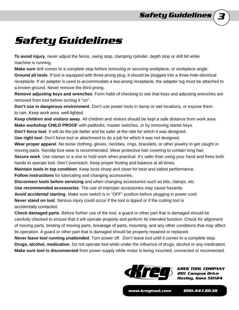
5DK1100 FP / DK1100 TP - Pneumatic Models
Parts Diagram

6DK3100 Electric
Parts Diagram

7
Changing Drill Bits
You can expect to drill between 4000 and 5000 holes in Oak with your #DKDB drill bit before the bit will need to be sharpened. This baseline was established using the factory settings described in the owner’s manual. Adjust your sharpening schedule for your settings and the material that you may be drilling.
IMPORTANT !
Before changing the drill bit, make certain your machine is DISCON-NECTED from the AIR SUPPLY and/or ELECTRICAL SUPPLY. Cycle the machine via the foot switch several times to remove air from the system. Without an air supply or electrical supply you can be certain the bit will not accidentally engage while you are performing mainte-nance.
Step 1: Disconnect the machine from the air supply and/or electrical supply.Step 2: Remove the Top Plate to gain access to the inside of the machine.Step 3: Loosen both Set-screws with the hex key that hold the drill bit in place inside the Drill Chuck.Step 4: Remove the Drill Bit by pushing forward out of the Drill
the Drill Chuck. Angle the Drill Bit slightly and pull clear of the Drill Guide Plate.Step 5: Insert a new or re-sharpened Drill Bit into the Drill Chuck, aligning the flat on the Drill Bit shank with the Set-Screws.Step 6: Tighten the Set-screws front and back to maintain equal pressure on the Drill Shaft.
Step 7: Reset the Counter to track Drill Bit life.
Chuck and into the Drill Guide Plate until the Drill Bit clears
DK1100 FE
Adjusting the Drill Bit Depth Stop
A Drill Bit Depth Stop is provided to stop the Drill Bit forward motion and control the Drill Feed Cylinder cycle. When the head of the Drill Bit Depth Stop fully engages the Depth Control Switch the forward motion of the Drill Bit is stopped and reversed to complete the drilling cycle. Before adjusting the Drill Bit Depth Stop make certain your machine is DISCONNECTED from the AIR SUPPLY and/or ELECTRICAL SUPPLY. Cycle the machine via the foot switch several times to remove air from the system. Without an air supply or electrical supply you can be certain the machine will not accidentally engage while you are performing maintenance. The Depth Control Adjuster should be adjusted so that the pilot point of the Drill Bit is just slightly away from the Fence when the Head has fully depressed the plunger of the Depth Control Switch. Make sure the Depth Control Adjuster is locked into position with the Lock Nut.
Step 1: Loosen the Lock Nut on the Depth Control Adjuster. Adjust the Depth Control Adjuster the approximate position.Step 2: Push the Drill Bit Drive Assembly forward till the Drill Bit pilot point is slightly away from the Fence.Step 3: Adjust the Drill Depth Control Adjuster till the Head fully depresses the plunger on the Depth Control Switch.Step 4: Tighten the Lock Nut to lock the Depth Control Adjuster in position.Step 5: Pull the Drill Bit Drive Assembly back into the resting position.
Set-screws
Drill Bit
Drill Chuck
Depth Control Adjuster
Lock Nut
Head
Depth Control Switch
8DK1100 FE continuned
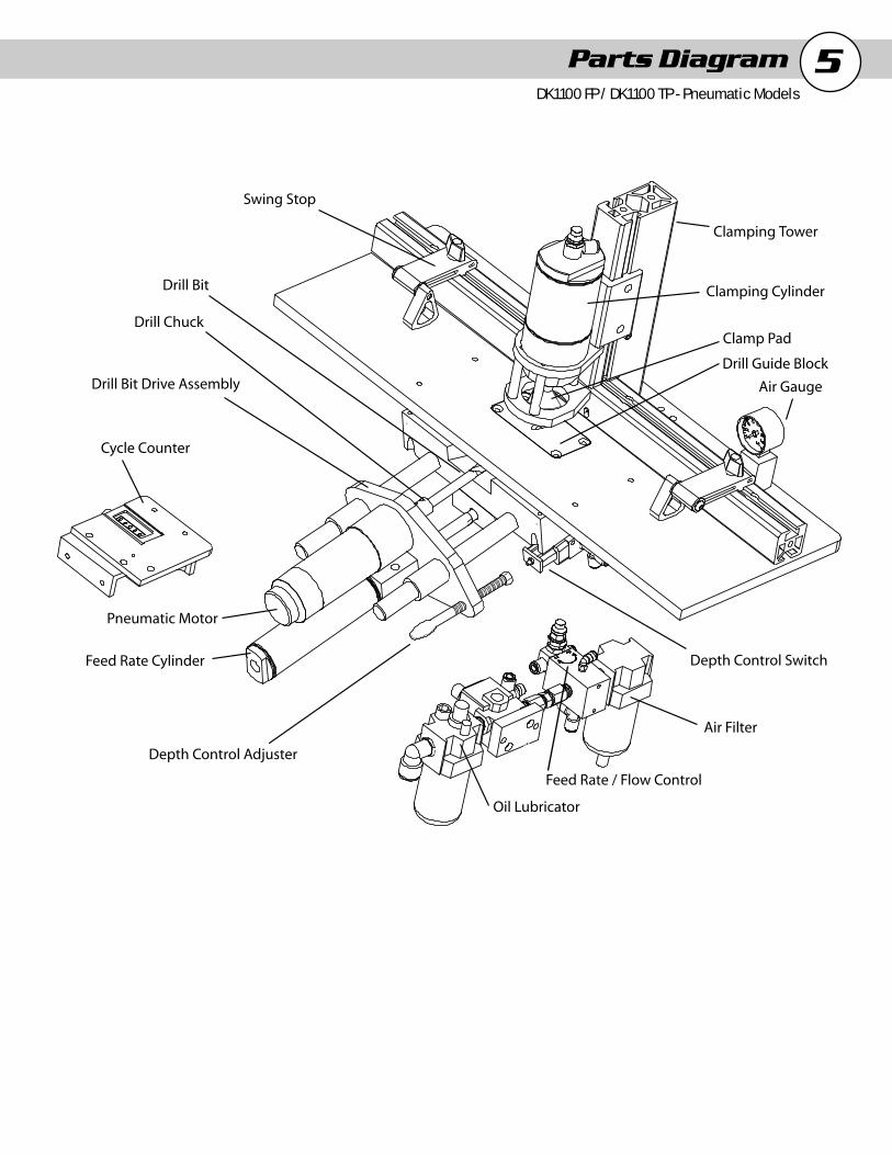
Adjusting the Fence Setting
The Fence can be adjusted to align the pocket hole to the center of material of different thicknesses. When adjusting the Fence make sure that the Fence remains perpendicular to the Guide Plate. A Reference Scale has been provided to approximate the fence setting for 1/2”, 3/4”, and 1-1/2” thick material. These correspond to the “A”, “B”, and “C” lines on the Reference Scale.
Step 1: Loosen the (4) Socket-head Cap Screws contained below the surface of the Fence.Step 2: Align the Fence perpendicular to the Guide Plate for the setting that corresponds to the material thickness.Step 3: Tighten the (4) Socket-head Cap Screws to lock the Fence into position.
Swing Stops
Two Swing Stops are provided to assist in drilling pocket holes in the same location on multiple work pieces of the same dimension. When the Swing Stop is not used, it will pivot out of the way to al-low the work piece to slide underneath and rest against the fence. To change the location of the Swing Stop simply loosen the Knob, move to the new location and tighten the Knob to lock the Swing Stop in position.
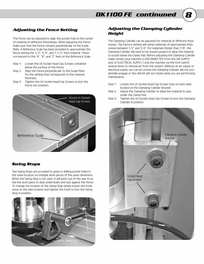
Adjusting the Clamping Cylinder Height
The Clamping Cylinder can be adjusted for material of different thick-nesses. The factory setting will clamp materials of approximate thick-nesses between 1/2” and 3/4”. For materials thicker than 7/8”, the Clamping Cylinder will need to be moved upward to allow the material to locate below the Clamp Pad. Before adjusting the Clamping Cylinder make certain your machine is DISCONNECTED from the AIR SUPPLY and/or ELECTRICAL SUPPLY. Cycle the machine via the foot switch several times to remove air from the system. Without an air supply or electrical supply you can be certain the Clamping Cylinder will not acci-dentally engage or the drill bit will not rotate while you are performing maintenance.
Step 1: Loosen the (4) Socket-head Cap Screws (two on each side) located on the Clamping Cylinder Bracket.Step 2: Adjust the Clamping Cylinder to allow the material to pass under the Clamp Pad.Step 3: Tighten the (4) Socket-head Cap Screws to lock the Clamping Cylinder in position.
Reference Scale
Access to Socket-Head Cap Screws
Knob
Swing Stop
Clamping Cylinder
Clamping CylinderBracket
Socket-headCap Screws

9Feed Rate Flow Control
The Feed Rate Control Valve allows the user to adjust the speed at which the drill bit advances into the material. The factory setting of this valve will maintain a consistent feed rate for various thick-nesses of different materials to optimize Drill Bit life. The Feed Rate Control Valve should only be adjusted when a faster or slower rate of Drill Bit feed is desired. This adjustment is only recommended for experienced users that consistently drill the same thickness of the same type of material on a daily basis. The Feed Rate Control Valve is adjusted by loosening the Locking Collar and rotating the Screw in the direction of the desired change in feed rate. “F” corresponds to a Faster feed rate, “S” corresponds to a Slower feed rate. Make these adjustments carefully as only a slight change in position will result in a large change of feed rate. Make certain to tighten the Locking Collar to prevent the Screw from accidentally drifting or vibrating out of adjustment
Clamping Duration Control
Clamping Duration Control allows the user to adjust the duration that the pneumatic clamp engages the material before, during, and after the drilling operation is performed. The factory setting of this valve will maintain the correct amount of time that the material is clamped while drilling. If the work piece lifts off of the Drill Guide Plate during drilling then the Clamping Duration Control will need to be adjusted. Loosen the Locking Collar and turn the Screw in the clockwise direction to increase the duration (more clamping time). Turning the Screw in the counter-clockwise direction decreases the duration (less clamping time). Make certain to tighten the Locking Collar to prevent the Screw from accidentally drifting or vibrating out of adjustment.
Belt Tension
Proper belt tension is necessary to maximize the efficiency of the Drill Bit. A simple adjustment has been provided to allow the user to properly maintain belt tension. Remember to check the belt tension often on the machine, especially in the first few hours of operation of a new machine. Before checking belt tension and during belt ten-sion adjustment make certain your machine is DISCONNECTED from the AIR SUPPLY and ELECTRICAL SUPPLY. Cycle the machine via the foot switch several times to remove air from the system. Without an air supply or electrical supply you can be certain the motor will not accidentally rotate while you are performing maintenance.
Step 1: Loosen the top 5/16” nut above the springs w/wrench on the Motor Mounting Plate.Step 2: Tighten the other 5/16” nut against the springs to provide adequate belt tension for proper operation.Step 3: Re-tighten the 5/16” nut against the other 5/16” nut with wrench as a jam nut to maintain proper tension on the belt.
DK1100 FE continued
Screw
Locking Collar
Locking Locking CollarCollar
ScrewScrew

10DK1100 TP / FP
Changing Drill Bits
You can expect to drill between 4000 and 5000 holes in Oak with your #DKDB drill bit before the bit will need to be sharpened. This baseline was established using the factory settings described in the owner’s manual. Adjust your sharpening schedule for your settings and the material that you may be drilling.
IMPORTANT !
Before changing the drill bit, make certain your machine is DISCONNECTED from the AIR SUPPLY and/or ELECTRICAL SUPPLY. Cycle the machine via the foot switch several times to remove air from the system. Without an air supply or electrical supply you can be certain the bit will not accidentally engage while you are performing maintenance.
Step 1: Disconnect the machine from the air supply and/or electrical supply.Step 2: Remove the Top Plate to gain access to the inside of the machine.Step 3: Loosen both Set-screws with the hex key that hold the drill bit in place inside the Drill Chuck.Step 4: Remove the Drill Bit by pushing forward out of the Drill Chuck and into the Drill Guide Plate until the Drill Bit clears the Drill Chuck. Angle the Drill Bit slightly and pull clear of the Drill Guide Plate.Step 5: Insert a new or re-sharpened Drill Bit into the Drill Chuck, aligning the flat on the Drill Bit shank with the Set-Screws.Step 6: Tighten the Set-screws front and back to maintain equal pressure on the Drill Shaft.
Step 7: Reset the Counter to track Drill Bit life
Adjusting the Drill Bit Depth Stop
A Drill Bit Depth Stop is provided to stop the Drill Bit forward motion and control the Drill Feed Cylinder cycle. When the head of the Drill Bit Depth Stop fully engages the Depth Control Switch the forward motion of the Drill Bit is stopped and reversed to complete the drilling cycle. Before adjusting the Drill Bit Depth Stop make certain your machine is DISCONNECTED from the AIR SUPPLY and/or ELECTRI-CAL SUPPLY. Cycle the machine via the foot switch several times to remove air from the system. Without an air supply or electrical supply you can be certain the machine will not accidentally engage while you are performing maintenance. The Depth Control Adjuster should be adjusted so that the pilot point of the Drill Bit is just slightly away from the Fence when the Head has fully depressed the plunger of the Depth Control Switch. Make sure the Depth Control Adjuster is locked into position with the Lock Nut.
Step 1: Loosen the Lock Nut on the Depth Control Adjuster. Adjust the Depth Control Adjuster the approximate position.Step 2: Push the Drill Bit Drive Assembly forward till the Drill Bit pilot point is slightly away from the Fence.Step 3: Adjust the Drill Depth Control Adjuster till the Head
Step 4: Tighten the Lock Nut to lock the Depth Control Adjuster in position.Step 5: Pull the Drill Bit Drive Assembly back into the resting position.
fully depresses the plunger on the Depth Control Switch.
Set-screws
Drill Bit
Drill Chuck
Depth Control Adjuster
Lock Nut
Head
Depth Control Switch

11
Adjusting the Fence Setting
The Fence can be adjusted to align the pocket hole to the center of material of different thicknesses. When adjusting the Fence make sure that the Fence remains perpendicular to the Guide Plate. A Reference Scale has been provided to approximate the fence setting for 1/2”, 3/4”, and 1-1/2” thick material. These correspond to the “A”, “B”, and “C” lines on the Reference Scale.
Step 1: Loosen the (4) Socket-head Cap Screws contained below the surface of the Fence.Step 2: Align the Fence perpendicular to the Guide Plate for the setting that corresponds to the material thickness.Step 3: Tighten the (4) Socket-head Cap Screws to lock the Fence into position.
Swing Stops
Two Swing Stops are provided to assist in drilling pocket holes in the same location on multiple work pieces of the same dimension. When the Swing Stop is not used, it will pivot out of the way to allow the work piece to slide underneath and rest against the fence. To change the location of the Swing Stop simply loosen the Knob, move to the new location and tighten the Knob to lock the Swing Stop in position.
Adjusting the Clamping Cylinder Height
The Clamping Cylinder can be adjusted for material of different thicknesses. The factory setting will clamp materials of approxi-mate thicknesses between 1/2” and 3/4”. For materials thicker than 7/8”, the Clamping Cylinder will need to be moved upward to allow the material to locate below the Clamp Pad. Before adjust-ing the Clamping Cylinder make certain your machine is DISCON-NECTED from the AIR SUPPLY and/or ELECTRICAL SUPPLY. Cycle the machine via the foot switch several times to remove air from the system. Without an air supply or electrical supply you can be certain the Clamping Cylinder will not accidentally engage or the drill bit will not rotate while you are performing maintenance.
Step 1: Loosen the (4) Socket-head Cap Screws (two on each side) located on the Clamping Cylinder Bracket.Step 2: Adjust the Clamping Cylinder to allow the material to pass under the Clamp Pad.Step 3: Tighten the (4) Socket-head Cap Screws to lock the
Clamping Cylinder in position.
DK1100 TP / FP continued
Reference Scale
Access to Socket-Head Cap Screws
Knob
Swing Stop
Clamping Cylinder
Clamping CylinderBracket
Socket-headCap Screws
12
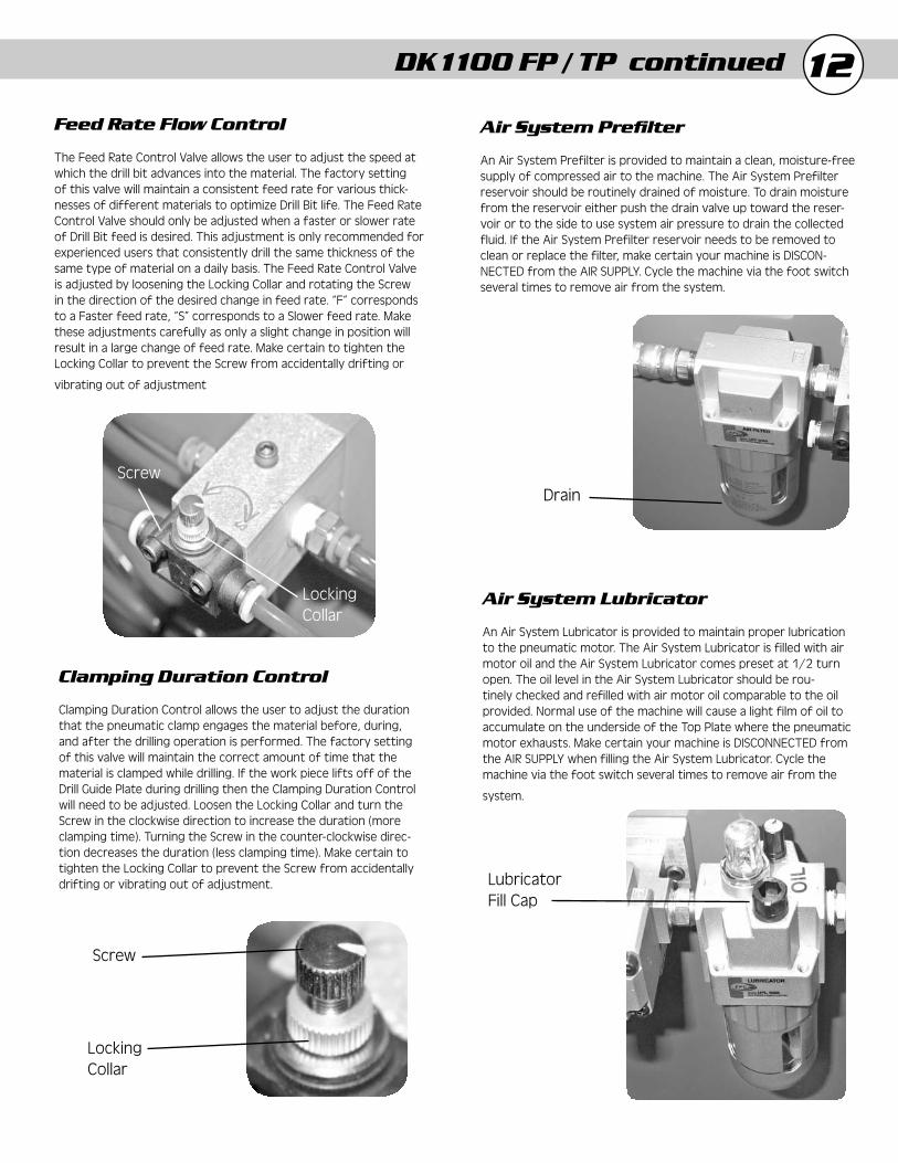
Feed Rate Flow Control
The Feed Rate Control Valve allows the user to adjust the speed at which the drill bit advances into the material. The factory setting of this valve will maintain a consistent feed rate for various thick-nesses of different materials to optimize Drill Bit life. The Feed Rate Control Valve should only be adjusted when a faster or slower rate of Drill Bit feed is desired. This adjustment is only recommended for experienced users that consistently drill the same thickness of the same type of material on a daily basis. The Feed Rate Control Valve is adjusted by loosening the Locking Collar and rotating the Screw in the direction of the desired change in feed rate. “F” corresponds to a Faster feed rate, “S” corresponds to a Slower feed rate. Make these adjustments carefully as only a slight change in position will result in a large change of feed rate. Make certain to tighten the Locking Collar to prevent the Screw from accidentally drifting or
vibrating out of adjustment
Clamping Duration Control
Clamping Duration Control allows the user to adjust the duration that the pneumatic clamp engages the material before, during, and after the drilling operation is performed. The factory setting of this valve will maintain the correct amount of time that the material is clamped while drilling. If the work piece lifts off of the Drill Guide Plate during drilling then the Clamping Duration Control will need to be adjusted. Loosen the Locking Collar and turn the Screw in the clockwise direction to increase the duration (more clamping time). Turning the Screw in the counter-clockwise direc-tion decreases the duration (less clamping time). Make certain to tighten the Locking Collar to prevent the Screw from accidentally drifting or vibrating out of adjustment.
Air System Prefi lter
An Air System Prefilter is provided to maintain a clean, moisture-free supply of compressed air to the machine. The Air System Prefilter reservoir should be routinely drained of moisture. To drain moisture from the reservoir either push the drain valve up toward the reser-voir or to the side to use system air pressure to drain the collected fluid. If the Air System Prefilter reservoir needs to be removed to clean or replace the filter, make certain your machine is DISCON-NECTED from the AIR SUPPLY. Cycle the machine via the foot switch several times to remove air from the system.
Air System Lubricator
An Air System Lubricator is provided to maintain proper lubrication to the pneumatic motor. The Air System Lubricator is filled with air motor oil and the Air System Lubricator comes preset at 1/2 turn open. The oil level in the Air System Lubricator should be rou-tinely checked and refilled with air motor oil comparable to the oil provided. Normal use of the machine will cause a light film of oil to accumulate on the underside of the Top Plate where the pneumatic motor exhausts. Make certain your machine is DISCONNECTED from the AIR SUPPLY when filling the Air System Lubricator. Cycle the machine via the foot switch several times to remove air from the
system.
DK1100 FP / TP continued
Screw
Locking Collar
Locking Locking CollarCollar
ScrewScrew
Drain
LubricatorLubricatorFill CapFill Cap
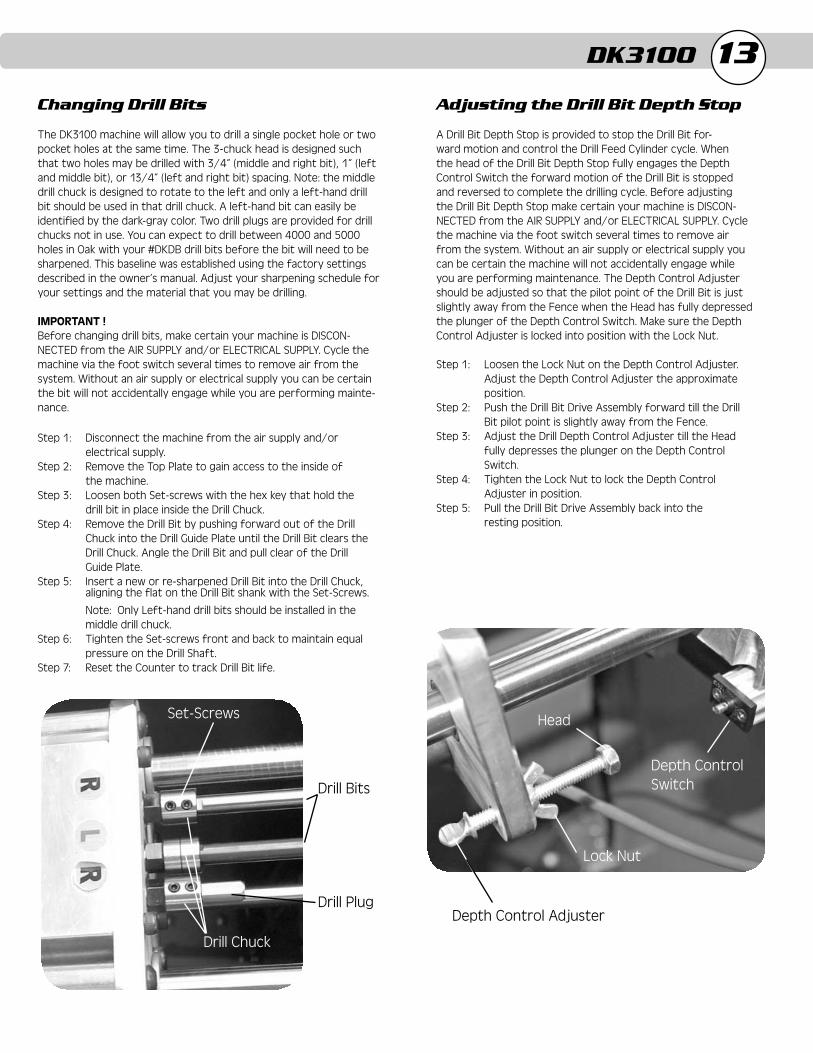
13Changing Drill Bits
The DK3100 machine will allow you to drill a single pocket hole or two pocket holes at the same time. The 3-chuck head is designed such that two holes may be drilled with 3/4” (middle and right bit), 1” (left and middle bit), or 13/4” (left and right bit) spacing. Note: the middle drill chuck is designed to rotate to the left and only a left-hand drill bit should be used in that drill chuck. A left-hand bit can easily be identified by the dark-gray color. Two drill plugs are provided for drill chucks not in use. You can expect to drill between 4000 and 5000 holes in Oak with your #DKDB drill bits before the bit will need to be sharpened. This baseline was established using the factory settings described in the owner’s manual. Adjust your sharpening schedule for your settings and the material that you may be drilling.
IMPORTANT !Before changing drill bits, make certain your machine is DISCON-NECTED from the AIR SUPPLY and/or ELECTRICAL SUPPLY. Cycle the machine via the foot switch several times to remove air from the system. Without an air supply or electrical supply you can be certain the bit will not accidentally engage while you are performing mainte-nance.
Step 1: Disconnect the machine from the air supply and/or electrical supply.Step 2: Remove the Top Plate to gain access to the inside of the machine.Step 3: Loosen both Set-screws with the hex key that hold the drill bit in place inside the Drill Chuck.Step 4: Remove the Drill Bit by pushing forward out of the Drill Chuck into the Drill Guide Plate until the Drill Bit clears the Drill Chuck. Angle the Drill Bit and pull clear of the Drill Guide Plate.Step 5: Insert a new or re-sharpened Drill Bit into the Drill Chuck,
Note: Only Left-hand drill bits should be installed in the middle drill chuck.Step 6: Tighten the Set-screws front and back to maintain equal pressure on the Drill Shaft.Step 7: Reset the Counter to track Drill Bit life.
aligning the flat on the Drill Bit shank with the Set-Screws.
DK3100
Adjusting the Drill Bit Depth Stop
A Drill Bit Depth Stop is provided to stop the Drill Bit for-ward motion and control the Drill Feed Cylinder cycle. When the head of the Drill Bit Depth Stop fully engages the Depth Control Switch the forward motion of the Drill Bit is stopped and reversed to complete the drilling cycle. Before adjusting the Drill Bit Depth Stop make certain your machine is DISCON-NECTED from the AIR SUPPLY and/or ELECTRICAL SUPPLY. Cycle the machine via the foot switch several times to remove air from the system. Without an air supply or electrical supply you can be certain the machine will not accidentally engage while you are performing maintenance. The Depth Control Adjuster should be adjusted so that the pilot point of the Drill Bit is just slightly away from the Fence when the Head has fully depressed the plunger of the Depth Control Switch. Make sure the Depth Control Adjuster is locked into position with the Lock Nut.
Step 1: Loosen the Lock Nut on the Depth Control Adjuster. Adjust the Depth Control Adjuster the approximate position.Step 2: Push the Drill Bit Drive Assembly forward till the Drill Bit pilot point is slightly away from the Fence.Step 3: Adjust the Drill Depth Control Adjuster till the Head fully depresses the plunger on the Depth Control Switch.Step 4: Tighten the Lock Nut to lock the Depth Control Adjuster in position.Step 5: Pull the Drill Bit Drive Assembly back into the resting position.
Depth Control Adjuster
Lock Nut
Head
Depth Control Switch
Set-Screws
Drill Bits
Drill Chuck
Drill Plug
14
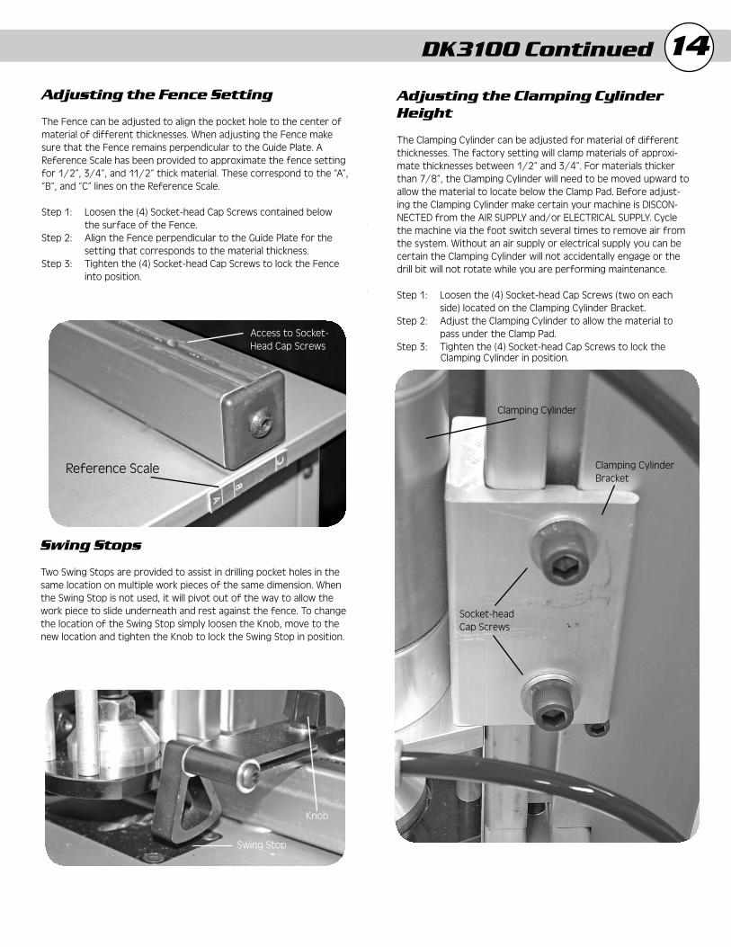
Adjusting the Fence Setting
The Fence can be adjusted to align the pocket hole to the center of material of different thicknesses. When adjusting the Fence make sure that the Fence remains perpendicular to the Guide Plate. A Reference Scale has been provided to approximate the fence setting for 1/2”, 3/4”, and 11/2” thick material. These correspond to the “A”, “B”, and “C” lines on the Reference Scale.
Step 1: Loosen the (4) Socket-head Cap Screws contained below the surface of the Fence.Step 2: Align the Fence perpendicular to the Guide Plate for the setting that corresponds to the material thickness.Step 3: Tighten the (4) Socket-head Cap Screws to lock the Fence into position.
Swing Stops
Two Swing Stops are provided to assist in drilling pocket holes in the same location on multiple work pieces of the same dimension. When the Swing Stop is not used, it will pivot out of the way to allow the work piece to slide underneath and rest against the fence. To change the location of the Swing Stop simply loosen the Knob, move to the new location and tighten the Knob to lock the Swing Stop in position.
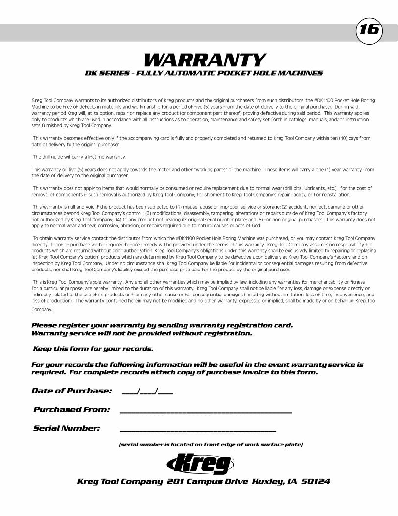
Adjusting the Clamping Cylinder Height
The Clamping Cylinder can be adjusted for material of different thicknesses. The factory setting will clamp materials of approxi-mate thicknesses between 1/2” and 3/4”. For materials thicker than 7/8”, the Clamping Cylinder will need to be moved upward to allow the material to locate below the Clamp Pad. Before adjust-ing the Clamping Cylinder make certain your machine is DISCON-NECTED from the AIR SUPPLY and/or ELECTRICAL SUPPLY. Cycle the machine via the foot switch several times to remove air from the system. Without an air supply or electrical supply you can be certain the Clamping Cylinder will not accidentally engage or the drill bit will not rotate while you are performing maintenance.
Step 1: Loosen the (4) Socket-head Cap Screws (two on each side) located on the Clamping Cylinder Bracket.Step 2: Adjust the Clamping Cylinder to allow the material to pass under the Clamp Pad.Step 3: Tighten the (4) Socket-head Cap Screws to lock the
Clamping Cylinder in position.
Reference Scale
Access to Socket-Head Cap Screws
Knob
Swing Stop
Clamping Cylinder
Clamping CylinderBracket
Socket-headCap Screws
DK3100 Continued

15
Feed Rate Flow Control
The Feed Rate Control Valve allows the user to adjust the speed at which the drill bit advances into the material. The factory setting of this valve will maintain a consistent feed rate for various thick-nesses of different materials to optimize Drill Bit life. The Feed Rate Control Valve should only be adjusted when a faster or slower rate of Drill Bit feed is desired. This adjustment is only recommended for experienced users that consistently drill the same thickness of the same type of material on a daily basis. The Feed Rate Control Valve is adjusted by loosening the Locking Collar and rotating the Screw in the direction of the desired change in feed rate. “F” corresponds to a Faster feed rate, “S” corresponds to a Slower feed rate. Make these adjustments carefully as only a slight change in position will result in a large change of feed rate. Make certain to tighten the Locking Collar to prevent the Screw from accidentally drifting or
vibrating out of adjustment
Clamping Duration Control
Clamping Duration Control allows the user to adjust the duration that the pneumatic clamp engages the material before, during, and after the drilling operation is performed. The factory setting of this valve will maintain the correct amount of time that the material is clamped while drilling. If the work piece lifts off of the Drill Guide Plate during drilling then the Clamping Duration Control will need to be adjusted. Loosen the Locking Collar and turn the Screw in the clockwise direction to increase the duration (more clamping time). Turning the Screw in the counter-clockwise direc-tion decreases the duration (less clamping time). Make certain to tighten the Locking Collar to prevent the Screw from accidentally drifting or vibrating out of adjustment.
Screw
Locking Collar
Locking Locking CollarCollar
ScrewScrew
DK3100 Continued
Air System Prefi lter
An Air System Prefilter is provided to maintain a clean, moisture-free supply of compressed air to the machine. The Air System Prefilter reservoir should be routinely drained of moisture. To drain moisture from the reservoir push the drain valve up toward the reservoir to use system air pressure to drain the collected fluid. If the Air System Prefilter reservoir needs to be removed to clean or replace the filter, make certain your machine is DISCONNECTED from the AIR SUPPLY. Cycle the machine via the foot switch
several times to remove air from the system.
Belt Tension
Proper belt tension is necessary to maximize the efficiency of the Drill Bit. A simple adjustment has been provided to allow the user to properly maintain belt tension. Remember to check the belt tension often on the machine, especially in the first few hours of operation of a new machine. Before checking belt tension and during belt tension adjustment make certain your machine is DISCONNECTED from the AIR SUPPLY and ELECTRICAL SUPPLY. Cycle the machine via the foot switch several times to remove air from the system. Without an air supply or electrical supply you can be certain the motor will not accidentally rotate while you are performing maintenance.
Step 1: Loosen the top 5/16” nut above the springs w/wrench on the Motor Mounting Plate.Step 2: Tighten the other 5/16” nut against the springs to provide adequate belt tension for proper operation.Step 3: Re-tighten the 5/16” nut against the other 5/16” nut with wrench as a jam nut to maintain proper tension on the belt.
Drain
16
WARRANTYDK SERIES - FULLY AUTOMATIC POCKET HOLE MACHINES
Kreg Tool Company warrants to its authorized distributors of Kreg products and the original purchasers from such distributors, the #DK1100 Pocket Hole Boring Machine to be free of defects in materials and workmanship for a period of five (5) years from the date of delivery to the original purchaser. During said warranty period Kreg will, at its option, repair or replace any product (or component part thereof) proving defective during said period. This warranty applies only to products which are used in accordance with all instructions as to operation, maintenance and safety set forth in catalogs, manuals, and/or instruction sets furnished by Kreg Tool Company.
This warranty becomes effective only if the accompanying card is fully and properly completed and returned to Kreg Tool Company within ten (10) days from date of delivery to the original purchaser.
The drill guide will carry a lifetime warranty. This warranty of five (5) years does not apply towards the motor and other “working parts” of the machine. These items will carry a one (1) year warranty from the date of delivery to the original purchaser.
This warranty does not apply to items that would normally be consumed or require replacement due to normal wear (drill bits, lubricants, etc.); for the cost of removal of components if such removal is authorized by Kreg Tool Company; for shipment to Kreg Tool Company’s repair facility; or for reinstallation.
This warranty is null and void if the product has been subjected to (1) misuse, abuse or improper service or storage; (2) accident, neglect, damage or other circumstances beyond Kreg Tool Company’s control; (3) modifications, disassembly, tampering, alterations or repairs outside of Kreg Tool Company’s factory not authorized by Kreg Tool Company; (4) to any product not bearing its original serial number plate; and (5) for non-original purchasers. This warranty does not apply to normal wear and tear, corrosion, abrasion, or repairs required due to natural causes or acts of God.
To obtain warranty service contact the distributor from which the #DK1100 Pocket Hole Boring Machine was purchased, or you may contact Kreg Tool Company directly. Proof of purchase will be required before remedy will be provided under the terms of this warranty. Kreg Tool Company assumes no responsibility for products which are returned without prior authorization. Kreg Tool Company’s obligations under this warranty shall be exclusively limited to repairing or replacing (at Kreg Tool Company’s option) products which are determined by Kreg Tool Company to be defective upon delivery at Kreg Tool Company’s factory, and on inspection by Kreg Tool Company. Under no circumstance shall Kreg Tool Company be liable for incidental or consequential damages resulting from defective products, nor shall Kreg Tool Company’s liability exceed the purchase price paid for the product by the original purchaser.
This is Kreg Tool Company’s sole warranty. Any and all other warranties which may be implied by law, including any warranties for merchantability or fitness for a particular purpose, are hereby limited to the duration of this warranty. Kreg Tool Company shall not be liable for any loss, damage or expense directly or indirectly related to the use of its products or from any other cause or for consequential damages (including without limitation, loss of time, inconvenience, and loss of production). The warranty contained herein may not be modified and no other warranty, expressed or implied, shall be made by or on behalf of Kreg Tool
Company.
Please register your warranty by sending warranty registration card.Warranty service will not be provided without registration.
Keep this form for your records.
For your records the following information will be useful in the event warranty service is required. For complete records attach copy of purchase invoice to this form.
Date of Purchase: ____/____/____
Purchased From: ____________________________________________
Serial Number: ________________________________________
(serial number is located on front edge of work surface plate)
Kreg Tool Company 201 Campus Drive Huxley, IA 50124