Embed Size (px)
Citation preview

Pro Pro MM aster & Ninja Proaster & Ninja ProInstruction ManualInstruction Manual
SPECIFICATION* MAIN ROTOR DIAMETER 49.10 in.* TAIL ROTOR DIAMETER 9.37 in.* OVERALL LENGTH 44.90 in.* HEIGHT 15.23 in.* GEAR RATIO 9.6 : 1 : 5.5* ENGINE 32 ~ 46* WEIGHT 5.8 LB
CENTURY HELICOPTER PRODUCTS9 / 1995

Building Instructions for Ninja ProBuilding Instructions for Ninja ProHelicopter KitHelicopter Kit
Congratulations you have just purchased the finest 30-46 size RC helicopter model on the market. The NinjaPro and Pro Master series of helicopters feature cutting edge design along with state of the art materials usedthroughout. Modern composite G-10 is used for the side frames for strength and to minimize vibration. An allmetal swashplate, metal washout and metal main rotor head are used to give precise control and handlingcharacteristics. Your Ninja Pro has been carefully researched and developed to give the highest performancelevel achievable with present technology. We are constantly reevaluating our line of kits as technology ad-vances in order to give you the highest degree of performance at all times. The instruction manual is dividedinto twenty sections.. The parts bags have also been separated into eleven different numbered bags. The bagsshould be opened in their numbered sequence with the exception of bag # eight as this is the hardware bagand will be used in all steps.
Explanation:* This instruction is written for 4 types of Ninja series, Ninja Pro 30, Ninja Pro 46, Ninja Pro 30 Master and Ninja Pro 46 Master.
* Use locktite at the point where this mark is shown.
* Use oil at the point where this mark is shown.
* Special attention at the point where this mark is shown caution !
OPERATE YOUR NINJA PRO HELICOPTER SAFELY
Your new Ninja Pro helicopter is state of the are using proven design techniques and the best materialsavailable. This is done for two reasons, first to give you the highest quality helicopter available and second,to insure it’s SAFE operation. It is imperative that the instructions be followed carefully during construction.This will insure that your Ninja Pro is properly assembled and safe to operate. We are not responsible forany damages or injuries caused by improper building, careless flying practices or the use of non-factory parts. We can not stress the importance of using ONLY factory replacement parts for your Ninja Pro.Every part in your Ninja Pro Kit has been thoroughly tested and made from the best materials. After marketparts may substandard and will compromise the safety of yourself and others at flying field. While flying,always do so away from any obstacles. This includes trees, power lines, animals, people...... in the otherwords, ANYTHING that can be hit if your model should go out of control. It is strongly recommended thatyou NEVER go flying alone, a second person can warn you if anything comes into your flying area.
22222

EDEDEDEDED
33333

Step 1 Lower side Frame Assembly1. Attach the 90 degree aluminum angle support (2002-079 Bag #1) to the “inside” of the lower side frame. Seedrawing below. Do this for the left and the right side. Each bracket is held on with three M3x8 cap head bolts andLocknuts.2. Attach two plastic battery tray mounts (2002-055 Bag #4) between the two lower side frames using four M3x8 self-tapping screws. Install the battery tray plate (2002-113 Bag #1) using four M3x8 self-tapping screws. Please note thatthere has been a change in the servo tray length. The mounts must be located at the very front and rear of the availablelocations. Double check to make sure that the hole provided for the front cannot mount is on the proper side of thebattery tray.3. Attach the two gyro plate cross members (2002-055) between the side frames using four M3x8 self-tapping screws.Add gyro plate (2002-119 Bag #1) on top of the cross members with four M3x6 countersink screws. An optional gyrolocation would be on the battery tray. This should only be considered if a center of gravity change is deemed necessary.
44444

M3X10103
147
149
151
099
M3X12
M3X10
147MASTER302
103M3X10
097
096101
M3X12
46 CUT THISAWAY
057
115
057
M3X8 SelfTapping
M3X8 SelfTapping
M3X6
098
101bent here to fit
Step 2 Engine/Clutch AssemblySlide the cooling fan (2002-115 Bag #1 for 30-size and 2002-097 Bag #2 for 46-size) onto the engine crankshaft. Thenslide the starter pulley (2002-149 Bag #4) on top of the fan. Add the engine nut and tighten it, but do not use anyLocktite. Install the centrifugal clutch (2002-147 Bag #4) to the pulley with two M3x10 bolts. Put the ball bearing(2002-103 Bag #4) in the center of the clutch.For 30-size engine: Install the engine to the engine mount (2002-099 bag #2) using four M3x12 bolts. Take the engineassembly and slide it into the side frames from the top side. Use four M3x10 bolts and four washers to secure theengine mount to the side frames. Do not tighten the four bolts completely. The position will be adjusted later. Dropthe fan shroud over the fan and between the lower frames. Use two M3x8 Philip head self-tapping screws to secure thestarter belt retaining clips (2002-057 bag #8) and the fan shroud to the side frames. The front end of the fan shroud issecured by a M3x8 Philip head screw on each side of the frames. Now, hang the engine starting belt (2002-109 Bag#4) around the fan shroud and secure in the starter belt retaining clips. It may be necessary to slightly squeeze the clipsin order to get a tight enough grip on the belt.
For 46-size engine: Install the engine to the engine mount (2002-101 Bag #2) using four M3x12 bolts. Take theengine assembly and slide it into the side frames from the top side. Use six M3x12 bolts and six washers to secure theengine mount to the side frames. Do not tighten the four bolts completely. The position will be adjusted later. The fanshroud for the 46-size engine is different from the 30-size. The 46-size shroud (2002-107 bag #2) comes in two pieces.Screw the two pieces together using two M3x8 Philip self-tapping screws. Add the fan bracket (2002-098 Bag #2 )between the rear of the fan shroud and the engine mount and adjust the fan to proper height. The bottom of the fanshould be flush with the bottom of the shroud. Add the two starting belt retainer clips (2002-057 Bag #8) on the fanshroud using two M3x8 Phillips screws and two washers. Now hang the engine starting belt (2002-109 Bag #4)around the fan shroud and secure the belt in the clips.The Pro Master has the addition of a top start system. This system is assembled and installed as a complete unit.! Donot use any ABC engine for shaft start system. Start by sanding the inside of the clutch bell (2002-303 BAG #4M) with220 grit sandpaper to aid the bond when installing the clutch lining. Thoroughly clean with solvent. Trim the liner soit fits snugly in the bell. Remove and reinstall using JB weld epoxy or slow CA to hold the liner in place. Press the4x9x4 ball bearing (2002-103 BAG #4M) into the inside of the clutch bell. Lightly grease the start shaft (2002-306BAG #4M) and insert into the clutch bell from the bottom. Take the double bearing block (2002-307 BAG #4M) andslip over the pinion shaft. It is advisable to use a little Locktite on the pinion shaft where it makes contact with the ballbearing. Clean off the end of the start shaft and slide the one way start adapter (2002-304 Bag #4M) in place. Install theset-screws that hold the adapter in place. Take note that one of the set-screws must seat on the flat on the start shaft andLocktite must be used.
55555
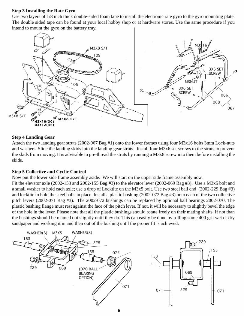
Step 3 Installing the Rate GyroUse two layers of 1/8 inch thick double-sided foam tape to install the electronic rate gyro to the gyro mounting plate.The double sided tape can be found at your local hobby shop or at hardware stores. Use the same procedure if youintend to mount the gyro on the battery tray.
Step 4 Landing GearAttach the two landing gear struts (2002-067 Bag #1) onto the lower frames using four M3x16 bolts 3mm Lock-nutsand washers. Slide the landing skids into the landing gear struts. Install four M3x6 set screws to the struts to preventthe skids from moving. It is advisable to pre-thread the struts by running a M3x8 screw into them before installing theskids.
Step 5 Collective and Cyclic ControlNow put the lower side frame assembly aside. We will start on the upper side frame assembly now.Fit the elevator axle (2002-153 and 2002-155 Bag #3) to the elevator lever (2002-069 Bag #3). Use a M3x5 bolt anda small washer to hold each axle; use a drop of Locktite on the M3x5 bolt. Use two steel ball end (2002-229 Bag #3)and locktite to hold the steel balls in place. Install a plastic bushing (2002-072 Bag #3) onto each of the two collectivepitch levers (2002-071 Bag #3). The 2002-072 bushings can be replaced by optional ball bearings 2002-070. Theplastic bushing flange must rest against the face of the pitch lever. If not, it will be necessary to slightly bevel the edgeof the hole in the lever. Please note that all the plastic bushings should rotate freely on their mating shafts. If not thanthe bushings should be reamed out slightly until they do. This can easily be done by rolling some 400 grit wet or drysandpaper and working it in and then out of the bushing until the proper fit is achieved.
109
M3X8 S/TM3X16
M3NUT
3X6 SETSCREW
3X6 SETSCREW
068
066
067
M3X10(30)M3X10(30)M3X10(30)M3X10(30)M3X10(30)M3X12(46)M3X12(46)M3X12(46)M3X12(46)M3X12(46)
M3X8 S/TM3X8 S/TM3X8 S/TM3X8 S/TM3X8 S/TM3X8 S/T
105
155
069
072
(070 BALLBEARINGOPTION)
229
071
229
WASHER(S)M3X5WASHER(S)
153
071 071
229
229
155
153
069
66666

Step 6 Upper Main Frames AssemblyFit the elevator control lever set and collective control axle (2002-157 Bag #3)between the top left and top right sideframes (2002-117 Bag #1). Press a plastic flanged bearing (2002-059 Bag #3) for the collective control lever axle intoinside of each side frame.The shorter elevator axle should be on the left side of the helicopter. Install two main bearingblocks (2002-083 Bag #4 or Bag #4M) onto the top side frames using four M3x35 bolts and four 3 mm nuts. The topbearing block should have the ball bearing facing up. The bottom bearing block should have the ball bearing facingdownward. After insert the collective control lever axle into the flanged bearing. Add the collective lever (2002-071Bag #3) to the collective axle. The lever needs to slide onto the elevator axle (2002-153 and 2002-155 Bag #3) withthe flange bearing facing toward the elevator lever. Please see the drawing.The 2002-059 bushings can be replaced by optional ball bearings (2002-061). Please note once again that thesebushings or ball bearings must move freely and with minimal freeplay in order for your helicopter to operate properly.It is imperative that the retaining screws be set at the proper tension. Too tight will bind the bearing and too loose willcreate unwanted freeplay. Fit the plastic tail boom holders (2002-085 Bag #4 or Bag #4M) in-between the upper sideframes. Also add the tail rotor servo mount plate (2002-073) outside the left side frame. The tail boom holders andservo mount are held by four M3x35 bolts and four nuts. Do not tighten the four nuts and bolts completely. They willtightened later, after the tail boom is installed.
Take the Y- shaped push-pull collective lever and install the 5mm control balls (2002-239 Bag #8) using M2x10screws and 2mm nuts. Now add the lever (2002-075 Bag #1) on top of the right side aluminum arm (2002-071 Bag#3). Use a M3x8 bolt and washer to secure the Y-shaped lever at the collective axle, and a M3x6 bolt to secure the Y-shaped lever to the 2002-071 arm. Install two M3x6 flanged plastic bushings (2002-160 Bag #3) The 2002-160 bush-ings can be replace by optional ball bearing 2002-022 on each 90 degree bell crank (2002-159 Bag #3). Install twosteel balls onto each bell crank using two M2x8 bolts, take care not to have any excess bolt protruding the oppositeside of the bell cranks. There are two 90 degree bell cranks, do this for both left and right side bell cranks. Slide a 90degree bell crank onto the left side elevator axle (2002-155 Bag #3) Use a M3x10 bolt and Locktite to retain the bellcrank onto the elevator control axle. Do not overtighten this M3x10 bolt; the bell crank should be able to pivot freely,but there should not be any free play.
125
125
083
083157
155
153
M3X8WASHER(S)
M3X8
WASHER(S)
M3X35071
071
117
117WASHER(S)
M3X8
071
117
059
061 (OPTIONBALL BEARING)
059
059
2X10
075
M2 NUT
M2 NUT
M3X6
M3X8
WASHER(S)
239
239
071
77777

Now, install a similar 90 degree bell crank to the right side. Install the steel elevator bell crank (2002-161 Bag #3) onthe right side elevator axle (2002-153 Bag #3). We suggest that you file a flat on the elevator axle where the set screwmakes contact. Put a 3x3mm set screw in the steel bell crank. Do not tighten the set screw very tightly yet, because theexact angle will be adjusted later. When permanently tightened be sure to use a drop of locktite on the elevator bellcrank. Fit the swashplate anti rotation bracket (2002-077 Bag #3) between the upper side frames. Fit two M3x35 boltsthrough the frames and the bracket. Secure them with two M3 nuts. Do not overtighten as this will only distort theframes.
Clutch Bell AssemblyRoughen the inner surface of the clutch bell (2002-127 Bag #4 or #4M) with #220 grit sand paper. Then, clean off the debris. Trial fit the clutch lining (2002-129Bag #4 or #4M) to the clutch bell, make sure it fits snugly. Once you aresatisfied, then remove the lining and permanently glue it back in using JB weldEpoxy, or slow CA glue. Fit the clutch bearing (2002-131 Bag #4 or 4M) andblock (2002-081 Bag #4 or #4M) in-between the upper side frames. The ballbearing should face downward. Use two M3x35 bolts to secure the bearing blockin place. Insert the clutch bell in the clutch bearing. It is recommended to applya little locktite to the pinion shaft where it inserts into the bearing.The Pro Master has the addition of a top start system. This system is assembledand installed as a complete unit. Start by sanding the inside of the clutch bell(2002-303 Bag #4M) with 220 grit sandpaper to aid the bond when installing theclutch lining. Thoroughly clean with solvent. Trim the liner so it fits snugly in thebell. Remove and reinstall using JB weld epoxy or slow CA to hold the liner inplace. Press the 4x9x4 ball bearing (2002-103 Bag #4M) into the inside of theclutch bell. Lightly grease the start shaft (2002-306 Bag #4M) and insert into theclutch bell from the bottom. Take the double bearing block with ball bearing(2002-307 bag #4M) and slip over the pinion shaft. It is advisable to use a littleLocktite on the pinion shaft where it makes contact with the ball bearing. Cleanoff the end of the start shaft and slide the adapter (2002-304 Bag #4M) in place.Install the set screws that hold the adapter in place. Take note that one of the setscrews must seat on the flat on the start shaft and Locktite must be used. Slide theassembly into place and secure the bearing block to the frames with two M3x35screws and nuts. Take note that the heads of these bolts must be on the same sideas the Y shaped collective bell crank.
085077
M3 NUTM3NUT
M3X35
M3X35
073
M3X10WASHER(S)
022 B A L LB A L LB A L LB A L LB A L LB E A R I N GB E A R I N GB E A R I N GB E A R I N GB E A R I N GO P T I O NO P T I O NO P T I O NO P T I O NO P T I O N
239
2X8
161
M3X6S E T S C R E WS E T S C R E WS E T S C R E WS E T S C R E WS E T S C R E W
159
160
160
159
2X8239
304OPTION
309305O P T I O NO P T I O NO P T I O NO P T I O NO P T I O N
3X6 SET
308
103
301
131
307
303
103
306
302
129
127
ROUGHEN INNERSURFACE
JB WELD EPOXYOR SLOW CA GLUE
JB
88888

Step 7 Tail Rotor DriveInsert the steel pinion shaft (2002-087 Bag #4 or #4M) into two bearing blocks (2002-081 Bag #4 or #4M). The ballbearings should face upward for both bearing blocks. Carefully smear a small amount of slow CA glue around bearing(2002-131 Bag #4 or 4M) before pushing bearing into bearing block (2002-081 Bag #4 or #4M). Add the plasticpulley (2002-133 Bag #4 or #4M) onto the pinion shaft. Insert a M3x8 bolt and a washer on top of the plastic pulley.Now fit this pulley assembly in-between the upper side frames. Use three M3x35 bolts and three locknuts to secure itto the frames. Fit a 40 mm long 3 mm stud (2002-094 Bag #3) into the rear hole of the bottom bearing block. Add athreaded spacer (2002-091 Bag #3) on each side of the 3 mm stud. Leave this assembly slightly loose so you can adjustthe gear mesh later.
M3x35
WASHER(S)
131
081
127
M3 NUT
M3x35
WASHER(S)
M3 NUT
303
306
307
3X6 SET
308
WASHER(S)
M3X8
133
131
081
131
087
094
081094
091
091
M3 NUTS
M3X35
M3X35M3X35
133
PRO MASTERPRO MASTERPRO MASTERPRO MASTERPRO MASTERCLUTCHCLUTCHCLUTCHCLUTCHCLUTCH
NINJA PRONINJA PRONINJA PRONINJA PRONINJA PROCLUTCHCLUTCHCLUTCHCLUTCHCLUTCH
99999
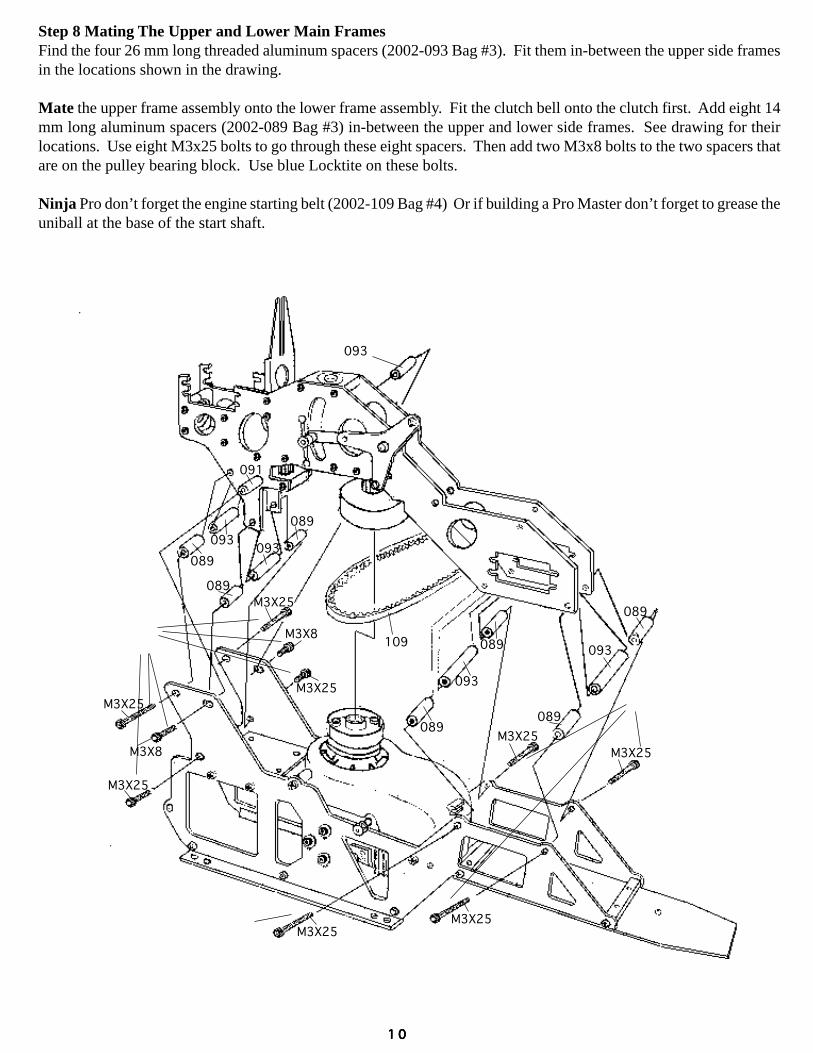
Step 8 Mating The Upper and Lower Main FramesFind the four 26 mm long threaded aluminum spacers (2002-093 Bag #3). Fit them in-between the upper side framesin the locations shown in the drawing.
Mate the upper frame assembly onto the lower frame assembly. Fit the clutch bell onto the clutch first. Add eight 14mm long aluminum spacers (2002-089 Bag #3) in-between the upper and lower side frames. See drawing for theirlocations. Use eight M3x25 bolts to go through these eight spacers. Then add two M3x8 bolts to the two spacers thatare on the pulley bearing block. Use blue Locktite on these bolts.
Ninja Pro don’t forget the engine starting belt (2002-109 Bag #4) Or if building a Pro Master don’t forget to grease theuniball at the base of the start shaft.
093
089
091
089
093
089093
089
093
089
093
089
089
109
M3X25M3X25
M3X25M3X25
M3X25
M3X25
M3X25
M3X25
M3X8
M3X8
1 01 01 01 01 0

Step 9 Main Rotor HeadInsert the metal center hub (2002-003 Bag #5) into the metal center yoke (2002-001 Bag #5). Add a M3x8 bolt oneach side of the yoke. Use blue Locktite on the two bolts. (2002-001, 2002-003) Smear some Vaseline on the tworubber dampers (2002-011 Bag #5). Then insert one damper on each side of the yoke. Slide the feathering spindle(2002-005 Bag #5) through the rubber damper and the yoke.Find the two blade grips (2002-007 Bag #5) note that the four main blade bearings (2002-008 Bag #5) are pre-installed in the blade grip. Add the metal pitch control arm (2002-009 Bag #5) onto the blade grip using a single M3x6bolt. Add the steel pitch control ball stud (2002-231 Bag#1) to the pitch control arm (2002-009 Bag #5). Use Locktiteon the pitch are and pivot control ball.Slide the completed blade grip onto the feathering spindle (2002-005 Bag #5). Insert a M3.5x12 bolt and a washerthrough the blade grip to secure the hub to the spindle. Use Locktite on this bolt ! Do not over tighten as this will onlymushroom the shaft and make bearing removal difficult.
Slide the seesaw (2002-017 Bag #5) onto the center hub. Fit two flanged plastic bearings (2002-160 Bag #3) or theflanged ball bearings (2002-022 OP) if you are building a Ninja pro master , into the center hole of the seesaw. Securethe seesaw to the hub by using a M3x6 bolt through each flanged bearing. Tighten the two M3x8 bolts sufficiently toremove all free play, but the seesaw should still be able to move smoothly ! Use Locktite on the bolts. On this and thefollowing steps it cannot be stressed enough the importance of the seesaw and mixing arms pivoting freely withoutexcessive play. The use of Locktite is mandatory during these steps.
Fit two flanged plastic bearings (2002-160) or non-flanged ball bearings (2002-022A Bag #4M) if building a ProMaster onto each mixing arm (2002-019 Bag #5). Add the two mixing arms (2002-019) onto the seesaw. Use aM3x10 bolt with Locktite to secure the mixing arm to the seesaw. Tighten the M3x10 bolts sufficiently to remove allfree play, but the arms should still be able to move smoothly. Fit steel ball (2002-239) onto mixing arm (2002-019) useM2x8 screw with nut and Locktite.
Insert two plastic flanged bearing (2002-160) or (2002-022A) if building a Pro Master on the seesaw. Slide the flybar(2002-015 Bag #10) through the flanged bearings and the seesaw ! Use a ruler to check to make sure equal lengthsticks out on either side of the seesaw. Add a flybar control arm (2002-013 Bag #5) on either side of the seesaw. Coatthe threads of each M3x6 set screw with Locktite, then fit a set screw inside each control arm. Make sure both arms arelevel ! Insert a 3mm locknut into the underside of each control paddle (2002-253 Bag #5) Then screw the paddlesonto the flybar. Wick some thin CA glue into the paddle hole after threading it onto the flybar ! Make sure the twopaddles are at same distance from the control arm and are level with the control arms. This is an extremely importantstep you can follow the picture to cut a flybar jig template. Check the flybar balance by letting the seesaw pivot on itsbushings. Add tape to the light paddle until balance is achieved.
M3x8
M3x8
003
011
005
005 231
007A008
007008
009
043
001
3.5X12
WASHER(S)
M3 NUT
M3X25
M3X6
CN2135 HEAD BUTTON (PURPLE)OPTIONCN2136 HEAD BUTTON (GOLD)OPTION
CN2122 CARBONSTIFFENER FORFLY BARS(OPTION)
M3 NUT
1 11 11 11 11 1

121
021
023
023
025
032
031
229229
229
226226
160
160
022A
230
230 022A
PRO MASTER
4 X 4 S E T4 X 4 S E T4 X 4 S E T4 X 4 S E T4 X 4 S E TS C R E WS C R E WS C R E WS C R E WS C R E W
M3X10 M 2 X 1 2M 2 X 1 2M 2 X 1 2M 2 X 1 2M 2 X 1 2
239M 2 N U TM 2 N U TM 2 N U TM 2 N U TM 2 N U T
M 3 X 3M 3 X 3M 3 X 3M 3 X 3M 3 X 3S E TS E TS E TS E TS E T
M3X16
013
013
160230
015
253
019160
160
M3x6 160
M3X10
230017
230M3X3
239
M2NUT
MASTERUSE 022HERE
M2X8
MASTERUSE 022AHERECN2029A
FLY BARWEIGHTS(OPTION)
CUT A FLY BAR JIG TEMPLATE
SOME THINCA GLUE MAKE SURE
PADDLES & ARMARE LEVEL
The Pro Master has all of these plastic bearings replaced with ball bearings. The installation is the same except thatsome small micro washers 3x4.5x0.5T are used in-between the ball bearing and the part it mates against.
Step 10 Washout and SwashplateFind the metal washout mixing base (2002-021 Bag #6) and the two metal washout arms (2002-023 Bag #6). Insert aplastic flanged bearing (2002-160) Or 2002-160 ball bearing if building a Pro Master onto either side of the washoutarm. Attach the washout arm to the mixing base with a M3x10 bolt. Tighten the M3x10 bolts sufficiently to removeall free play, but the arms should still be able to move smoothly.Put a plastic radius link (2002-025 Bag #5)on each washout arm. Slide a 2 mm pin throughthe radius link and the washout arm tosecure them. Insert a 3 mm set screwin the washout arm. This set screw isused to secure the pin. Add a metalspacer and steel ball and a M2x10bolt on each washout arm. Secure theM2x10 bolt with a 2 mm nut(2002-239 Bag #8).Fit three short threaded steel balls(2002-229 Bag #3) onto three outsidearms on the swashplate ! Use Locktiteon all these threaded balls. Be carefulnot to scratch or overtighten the balls.They are easily damaged duringinstallation. For the swashplateantirotation arm (2002-032 Bag #6)fit a M3x16 bolt with the plastic sleeve,a brass spacer, and special threadedsteel ball and another brass spacer;see drawing ! Use Locktite on the bolt.Fit four long threaded steel balls(2002-226 Bag #5) onto the four holeson the inside swashplate ring. Seedrawing below. Use Locktite on allthese threaded balls.
1 21 21 21 21 2
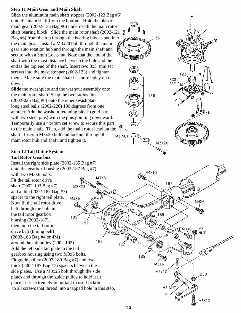
Step 11 Main Gear and Main ShaftSlide the aluminum main shaft stopper (2002-123 Bag #6)onto the main shaft from the bottom. Hold the plasticmain gear (2002-135 Bag #6) underneath the main rotorshaft bearing block. Slide the main rotor shaft (2002-121Bag #6) from the top through the bearing blocks and intothe main gear. Install a M3x20 bolt through the maingear auto rotation hub and through the main shaft andsecure with a 3mm Lock-nut. Note that the end of theshaft with the most distance between the hole and theend is the top end of the shaft. Insert two 3x3 mm setscrews into the mast stopper (2002-123) and tightenthem. Make sure the main shaft has nofreeplay up ordown.Slide the swashplate and the washout assembly ontothe main rotor shaft. Snap the two radius links(2002-025 Bag #6) onto the inner swashplatelong steel balls (2002-226) 180 degrees from oneanother. Add the washout retaining block (gold partwith two steel pins) with the pins pointing downward.Temporarily use a 4x4mm set screw to secure this partto the main shaft. Then, add the main rotor head on theshaft. Insert a M3x20 bolt and locknut through themain rotor hub and shaft, and tighten it.
Step 12 Tail Rotor SystemTail Rotor GearboxInstall the right side plate (2002-185 Bag #7)onto the gearbox housing (2002-187 Bag #7)with two M3x6 bolts.Fit the tail rotor driveshaft (2002-193 Bag #7)and a thin (2002-187 Bag #7)spacer to the right tail plate.Now fit the tail rotor drivebelt through the hole inthe tail rotor gearboxhousing (2002-187),then loop the tail rotordrive belt (timing belt)(2002-183 Bag #4 or 4M)around the tail pulley (2002-193).Add the left side tail plate to the tailgearbox housing using two M3x6 bolts.Fit guide pulley (2002-189 Bag #7) and twothick (2002-187 Bag #7) spacers between theside plates. Use a M3x25 bolt through the sideplates and through the guide pulley to hold it inplace ! It is extremely important to use Locktite to all screws that thread into a tapped hole in this step.
135
136
M3X20
M3 NUT
123
3X3SET
187
187
187
M3X25
M3X6
M3X6
187
197
185
189
M3X6
M3X6
183
M3X6 M3NUT
187
185
185
M3X10
191
M2 NUT
M2x10230
M4X6
M4X10
1 31 31 31 31 3
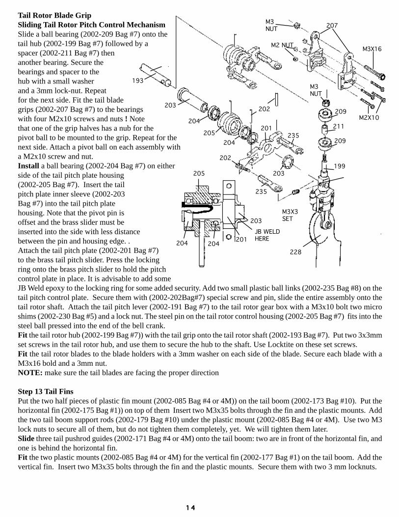
Tail Rotor Blade GripSliding Tail Rotor Pitch Control MechanismSlide a ball bearing (2002-209 Bag #7) onto thetail hub (2002-199 Bag #7) followed by aspacer (2002-211 Bag #7) thenanother bearing. Secure thebearings and spacer to thehub with a small washerand a 3mm lock-nut. Repeatfor the next side. Fit the tail bladegrips (2002-207 Bag #7) to the bearingswith four M2x10 screws and nuts ! Notethat one of the grip halves has a nub for thepivot ball to be mounted to the grip. Repeat for thenext side. Attach a pivot ball on each assembly witha M2x10 screw and nut.Install a ball bearing (2002-204 Bag #7) on eitherside of the tail pitch plate housing(2002-205 Bag #7). Insert the tailpitch plate inner sleeve (2002-203Bag #7) into the tail pitch platehousing. Note that the pivot pin isoffset and the brass slider must beinserted into the side with less distancebetween the pin and housing edge. .Attach the tail pitch plate (2002-201 Bag #7)to the brass tail pitch slider. Press the lockingring onto the brass pitch slider to hold the pitchcontrol plate in place. It is advisable to add someJB Weld epoxy to the locking ring for some added security. Add two small plastic ball links (2002-235 Bag #8) on thetail pitch control plate. Secure them with (2002-202Bag#7) special screw and pin, slide the entire assembly onto thetail rotor shaft. Attach the tail pitch lever (2002-191 Bag #7) to the tail rotor gear box with a M3x10 bolt two microshims (2002-230 Bag #5) and a lock nut. The steel pin on the tail rotor control housing (2002-205 Bag #7) fits into thesteel ball pressed into the end of the bell crank.Fit the tail rotor hub (2002-199 Bag #7)) with the tail grip onto the tail rotor shaft (2002-193 Bag #7). Put two 3x3mmset screws in the tail rotor hub, and use them to secure the hub to the shaft. Use Locktite on these set screws.Fit the tail rotor blades to the blade holders with a 3mm washer on each side of the blade. Secure each blade with aM3x16 bold and a 3mm nut.NOTE: make sure the tail blades are facing the proper direction
Step 13 Tail FinsPut the two half pieces of plastic fin mount (2002-085 Bag #4 or 4M)) on the tail boom (2002-173 Bag #10). Put thehorizontal fin (2002-175 Bag #1)) on top of them Insert two M3x35 bolts through the fin and the plastic mounts. Addthe two tail boom support rods (2002-179 Bag #10) under the plastic mount (2002-085 Bag #4 or 4M). Use two M3lock nuts to secure all of them, but do not tighten them completely, yet. We will tighten them later.Slide three tail pushrod guides (2002-171 Bag #4 or 4M) onto the tail boom: two are in front of the horizontal fin, andone is behind the horizontal fin.Fit the two plastic mounts (2002-085 Bag #4 or 4M) for the vertical fin (2002-177 Bag #1) on the tail boom. Add thevertical fin. Insert two M3x35 bolts through the fin and the plastic mounts. Secure them with two 3 mm locknuts.
193
203
204
204
205
203
235
235
201
202
202
203
205
204204
228
M3X3SET
M3NUT
M3X16M2 NUT
M2X10
207
209
209
211
199
M3NUT
201JB WELDHERE
1 41 41 41 41 4

Step 13 Tail Fins
Step 14 Mating Tail Boom to the Main FramesFeed the tail drive belt (2002-183 Bag #4) through the tail boom starting with the end with two holes. A piece of wirewith a hook bent into it works well for pulling the belt through. Fit the tail boom (2002-173 BAG #10) into the upperside frames. Loop the drive belt onto the front pulley. The belt should have a 90 degree turn inside the tail boom !Check to make sure when the main rotor is turning in the clockwise direction (viewed from the top), the tail rotorshould turn counter-clockwise when viewed from the right hand side. Adjust the belt tension by pulling on the tailboom. Do not over tighten the belt, it should not be too loose so the belt slips. Slowly, tighten the four M3x35 boltsthat hold the tail boom.Attach the front of the tail boom support rods to the lower main frames. Use two M3x8 bolts and a 57mm threadedcross member (2002-095 Bag #3) to secure the front of the tail boom support rods to the frames. Mount the aft end ofthe boom-struts to the horizontal fin mounts, making sure the horizontal fin is level tighten the two M3x35 boltsholding the horizontal fin and fin clamp together.
Step 15 Fuel TankAssemble the fuel tank (2002-063 Bag #9) carefully accordingto the drawing shown below. Use caution while bending thebrass tubing. Do not use any pliers as this will kink thetubing use your hand and make a smooth flowing bendto avoid kinking. Add one strip of double sided foam tape to the top surface of the tank so it will makecontact with the gyro plate mount. Slide the tankinto the side frames from the right hand side.The fuel line should come out of the righthand side of the helicopter.
M3x35
175
085
085
085
085
179
177
171
171
223
M3X35
173
M3 NUT
171
M3 NUT
RIGHT !
WRONG !(TOO TIGHT)
179
063
095
M3X10
Double sidedfoam tape
215
173
171
From mufflerpressure fitting
To engine carbure-tor
1 51 51 51 51 5

Step 16 Main Rotor BladesThe rotor blades that are included in your Ninja Pro kit comepre-finished and require no building. They howevershould be checked for balance before use. If you havea balancer follow the instructions that came withthe balancer. Next attach the blades to the rotorhead. Balance the Rotor head and blades on twodrinking glasses suspending the whole unit by theflybar. The heavy side will hang lower than the lightside. Add self-adhesive tape on the light blade on alocation that will result in the proper CG shift. Addthe tape until the rotor head hangs horizontally.
Step 17 Radio InstallationAll five servos are mounted with the screws that came with your radio system with the exception of the aft twoscrews that hold the elevator servo. These two are replaced by two M3x8 self tapping screws. They are screwedtrough the cutouts in the frame and into the plastic servo mounting plates (2002-169 BAG #3) located with theplastic parts tree. Mount the five servos as illustrated in the instructions.
Step 18 Making Up the Control Push rodsMake up all the control push rods according to the specified length shown in the drawing. Please note that thesedimensions are from end to end of the plastic rod-end and are only guidelines. You will have to fine adjust themaccording to your particular servos.
#2002-213 ELEVATOR: Total 91 mm for JR servos ( 2 )(Use 68mm rod,see FIG #7 ) Total 92 mm for Futaba servos (2)
#2002-217 COLLECTIVE: Total 117 mm for JR servos (2)(Use 80mm rod,see FIG #2) Total 118 mm for Futaba servos (2)
#2002-215 ROLL(AILERON): Total131 mm for JR servos (2)(Use 100mm rod,see FIG #1 Total 132 mm for Futaba servos (2) & FIG #3 Slightly bent 10 degree)
#2002-221 SWASHPLATE: Total 69mm (4)(Use 40mm rod, seeFIG #3A & FIG#3B)
#2002-221 PITCH ( long ): Total 66mm ( 2 )(Use 40 mm rod, see FIG #4 )
#2002-225 PITCH ( short ): Total 36mm ( 2 )(Use10mm rod, see FIG #4 )
#2002-219 FLYBAR: Total 47mm (2 )(Use 25mm rod See FIG #5)
#2002-221 THROTTLE: Total 80 mm (1 )(Use 40 mm rod, see FIG #6)
# 2002-215 / 223 RUDDER: Total 618mm (1 )(Use 100 & 476 mm rod, see FIG #8)
EXSAMPLE:2002-217
TOTAL 117mm(JR)USE 80mm ROD
SEE FIG.# 2 117MM
80MM
CUT THISWHITE SHRINKCOVER OFFTHEN USE THINCA GLUE HERE
1 61 61 61 61 6

Use this pitch gauge1. Cut a 1:1 pitch gauge2. Put the gauge into the blade holder of the rotor head.3. Makesure the flybar parallel to the tail boom.4. Referring to the table bellow, set the flybar to each pitch gauge line, and read the pitch.5. Adjust your transmitter referring to the data of next page.
Use this flybar jig template1. Cut two 1:1 template.2. Referring step 9 main rotor head to setup.
CUT A FLY BAR JIG TEMPLATE
Add tape on thelighter bladeAccuratech main blade balancer
with C.G checker (Option) # CN2052can help you to find out the positionof C.G and balance a pair of the mainrotor blade.
1 71 71 71 71 7

213
213
165
163
229
233166
ELEVATORSERVO
ELEVATORELEVATORELEVATORELEVATORELEVATORLINKAGEL INKAGEL INKAGEL INKAGEL INKAGE
COLLECTIVE L INKAGECOLLECTIVE L INKAGECOLLECTIVE L INKAGECOLLECTIVE L INKAGECOLLECTIVE L INKAGE217
217
169
215
215
111
053
051
169
215
ROLL(AILERON)ROLL(AILERON)ROLL(AILERON)ROLL(AILERON)ROLL(AILERON)
THROTTLE(ENGINE)THROTTLE(ENGINE)THROTTLE(ENGINE)THROTTLE(ENGINE)THROTTLE(ENGINE)
221
RUDDER L INKAGERUDDER L INKAGERUDDER L INKAGERUDDER L INKAGERUDDER L INKAGE
215170 223
169
1 81 81 81 81 8

FIG.1FIG.1FIG.1FIG.1FIG.1
FIG.1FIG.1FIG.1FIG.1FIG.1
215
FIG.2FIG.2FIG.2FIG.2FIG.2
16-18mm221 221
FIG.3BFIG.3BFIG.3BFIG.3BFIG.3B
217
217
FIG.2FIG.2FIG.2FIG.2FIG.2
FIG.3AFIG.3AFIG.3AFIG.3AFIG.3A
221221
217
217
213
213
215
80
100
Step 19 SetupAll of the push rods now need to be fine adjusted tothe proper length. First adjust the roll push rods(2002-215 Bag #8) so that the top edge of the bellcranks are 80 degrees with the roll servo in theneutral position( Figure1 ). Now adjust thecollective rods (2002-217 Bag #8) so that thepitch arms are in the center of the slot withinthe main frame at collective half stick. Wheninstalling the control balls on the collective servospace the balls 6mm-8mm from the center of theservo wheel if using a standard radio. If using acomputer radio space the balls 8mm from thecenter of the output wheel. This will insure thatyou don't have too much collective travel.( FIGURE 2 ).
With this done four swashplate rods ( 2002-221Bag#8) so that the swashplate will be16-18mm above the upper bearing block ( Figure 3A/3B ).
1 91 91 91 91 9

Adjust the pitch control rod(2002-221 & 2002-225) asneeded to achieve 4-5degrees pitch ! ( Figure 4 )you need slightly bend#2002-221 to clear mixingarm too. Now using the highand low pitch trimmers onyour transmitter set the lowpitch to -1 degree and thehigh to +8 degrees !(see your radio instructionmanual). Adjust the flybarcontrol rods (2002-219 Bag #8)so that at half collective stick thewashout control arms will be level ( Figure 5 ).
Now lets move on to the throttle. Adjust the throttle rod(2002-221 ) and the servo arm so that at full low throttleand trim the carburetor will be completely closed, Youcan using throttle trim to set up idle speed.At half stick the carburetor should be open exactly 50%and at full stick the carburetor will be open to 100%.If you do not get to 100% open than your servo armis too short and must be lengthened ( Figure 6 ).
Adjust the elevator lever so that it is 3 degreesforward with the swashplate level ( Figure 7 ).The two elevator push rods ( 2002-213 Bag #8)must be the same length with the servo in theneutral position.
The last item that needs to be adjusted is the rudderpushrod. With the servo output arm set at 90 degreesto the servo, adjustthe pushrod so thatthe tail pitch leveris 90 degrees to thetail boom( Figure 8 ).
221
225
4-5
FIG.4FIG.4FIG.4FIG.4FIG.4
253
219
043
FIG.5FIG.5FIG.5FIG.5FIG.5
FIG.8FIG.8FIG.8FIG.8FIG.8
90
90223170215
213
213
FIG.7FIG.7FIG.7FIG.7FIG.7
221
221
221
50% (HOVER SPEED)
0% (LOW SPEED)
100% (FULL POWER)
FIG.6FIG.6FIG.6FIG.6FIG.6
2 02 02 02 02 0

Remember that this setting is at hover and must be fine tuned in conjunction with the revolution mixing on yourtransmitter. Set your control throws so that your swashplate tilts without any binding. Note that the swashplate musttilt to the left when left stick is applied and right when right is applied as well as forward and backward. Set the tailthrow so you will get slightly more travel to the right than to the left. This will help to balance the tail control feel
STEP 20 Canopy and DecalNinja Pro canopy.Start it trimming the outside flange to 1/4 of an inch.Then trim out the back of the canopy that wont beused. This is done by scribing a line about halfthe thickness of the plastic with a sharp hobbyknife. After the plastic has been scribed theplastic can be pulled apart rather easily.It is advisable to practice on some scapmaterial from the back first. Aftertrimming is done the canopy ispainted on the inside. We havefound the Pactra R/C paintsto work best. The blue protective film should be left on thecanopy to protect it from over spray during the painting. After the paint is dry glue the two halves together with Zap aDap a Goo. Use clothespins to hold the two halves together while the glue dries. After the glue dries remove theprotective film and admire your canopy.
Pro Master Canopy.The Pro master canopy is molded out of white styrene plastic. The right sideof the canopy has a molded- in lip that will allow the canopy halves to overlapwhen finished. Trim this lip to 3/16 inch, remove the back and cockpit area.The left side of the canopy is simply trimmed to a strait line again remove theback and cockpit area Trial fit the two halves together by taping them togetherfrom the inside. This will tell you if you need to do more trimming on the leftside or not. When you are satisfied with the fit, tape the two halve togetherfrom the inside once again. Carefully wick some liquid plastic modelcement into the joint between the two halves. When the glue has driedremove the tape from the inside. It is advisable to go over the insideof the seam with a bead of Zap a Dap a Goo. Next trim the windshieldwith a pair of curved scissors following the provided line.Tape the windshield to the canopy and again carefully wicksome liquid model cement into the seam. After this isdry apply the decals and you are finished.
23
mm
23
mm
23
mm
23
mm
23
mm
2 9 m m2 9 m m2 9 m m2 9 m m2 9 m m
6 4 m m6 4 m m6 4 m m6 4 m m6 4 m m3 9 m
m
3 9 mm
3 9 mm
3 9 mm
3 9 mm
7 . 5 m m7 . 5 m m7 . 5 m m7 . 5 m m7 . 5 m m
2 12 12 12 12 1
F IG .10F IG .10F IG .10F IG .10F IG .10
F IG .9F IG .9F IG .9F IG .9F IG .9
LIFTS OFF50%
LIFTS LESSTHAN 50%TOO MUCHPITCH
M3X8
M3X8
049
049049
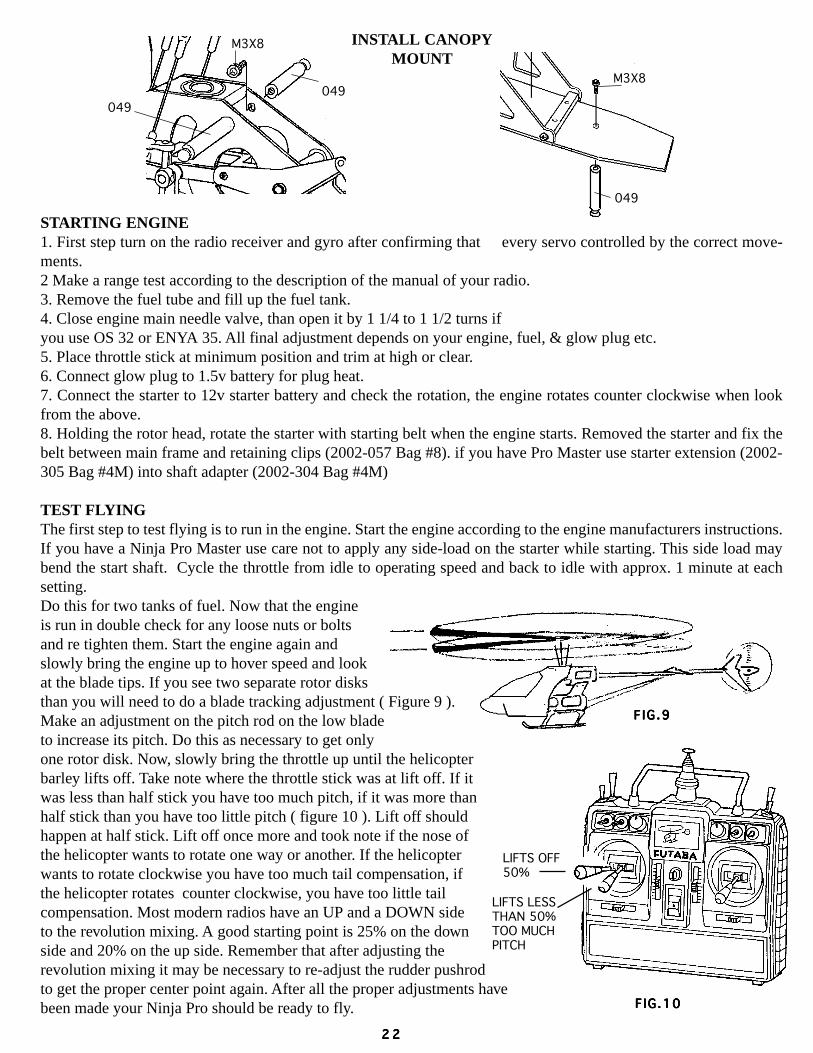
INSTALL CANOPYMOUNT
STARTING ENGINE1. First step turn on the radio receiver and gyro after confirming that every servo controlled by the correct move-ments.2 Make a range test according to the description of the manual of your radio.3. Remove the fuel tube and fill up the fuel tank.4. Close engine main needle valve, than open it by 1 1/4 to 1 1/2 turns ifyou use OS 32 or ENYA 35. All final adjustment depends on your engine, fuel, & glow plug etc.5. Place throttle stick at minimum position and trim at high or clear.6. Connect glow plug to 1.5v battery for plug heat.7. Connect the starter to 12v starter battery and check the rotation, the engine rotates counter clockwise when lookfrom the above.8. Holding the rotor head, rotate the starter with starting belt when the engine starts. Removed the starter and fix thebelt between main frame and retaining clips (2002-057 Bag #8). if you have Pro Master use starter extension (2002-305 Bag #4M) into shaft adapter (2002-304 Bag #4M)
TEST FLYINGThe first step to test flying is to run in the engine. Start the engine according to the engine manufacturers instructions.If you have a Ninja Pro Master use care not to apply any side-load on the starter while starting. This side load maybend the start shaft. Cycle the throttle from idle to operating speed and back to idle with approx. 1 minute at eachsetting.Do this for two tanks of fuel. Now that the engineis run in double check for any loose nuts or boltsand re tighten them. Start the engine again andslowly bring the engine up to hover speed and lookat the blade tips. If you see two separate rotor disksthan you will need to do a blade tracking adjustment ( Figure 9 ).Make an adjustment on the pitch rod on the low bladeto increase its pitch. Do this as necessary to get onlyone rotor disk. Now, slowly bring the throttle up until the helicopterbarley lifts off. Take note where the throttle stick was at lift off. If itwas less than half stick you have too much pitch, if it was more thanhalf stick than you have too little pitch ( figure 10 ). Lift off shouldhappen at half stick. Lift off once more and took note if the nose ofthe helicopter wants to rotate one way or another. If the helicopterwants to rotate clockwise you have too much tail compensation, ifthe helicopter rotates counter clockwise, you have too little tailcompensation. Most modern radios have an UP and a DOWN sideto the revolution mixing. A good starting point is 25% on the downside and 20% on the up side. Remember that after adjusting therevolution mixing it may be necessary to re-adjust the rudder pushrodto get the proper center point again. After all the proper adjustments havebeen made your Ninja Pro should be ready to fly.
2 22 22 22 22 2

Collective and Throttle:Slowly raise the throttle stick to HIGH,Helicopter should be lifts off at haft stick open,When helicopter is just about to take off, it inclinesto some directions. Correct the inclination by usingyour radio trim.
Rudder:When the helicopter is just about to take off,make a correction trim first then use rudder stickto control Left & Right, Note! Now is good timeto give your gyro a final adjustment. (see yourGYRO manual.)
Elevator:When the helicopter is just about to take off,make a correction trim first then use elevator stickto control Forward & Backward.
Roll(Ailer on):When the helicopter is just about to take off,make a correction trim first then use Aileron stickto control slide to Left or slide to the Right..
Ninja Pro 30-46 Helicopter Kit Replacement Parts List2002-000 Ninja Metric Hardware Pack .................... 1 19.95 D2002-007 Main Blade Grip ....................................... 1 28.95 D2002-007A Spacer ....................................................... 2 3.00 D2002-008 Blade Grip Bearing 5x13x4 ...................... 2 11.95 D2002-009 Pitch Arm .................................................. 2 14.95 D2002-010 Main Blade Grip Assembly ...................... 1 88.95 D2002-011 Damper Rubber ......................................... 4 5.95 D2002-013 Flybar Control Arm................................... 1 8.95 D2002-015 Spring Steel Flybar ................................... 1 4.95 D2002-017 Seesaw ...................................................... 1 16.50 D2002-019 Seesaw Arm .............................................. 2 16.50 D2002-020 Seesaw Ball Bearing 3x7x3F (OP) ........... 1 14.50 D2002-021 Washout Base Unit .................................... 1 26.50 D2002-022 Ball Bearing 3x6x2.5F (OP).....................4 29.95 D2002-022A Ball Bearing 3x6x2.5 (Master) ................4 17.95 D2002-023 Washout Arm ............................................ 2 18.50 D2002-024 Washout Assembly (W/Pl Bearing) .......... 1 49.95 D2002-025 Radius Link ............................................... 2 4.95 D2002-027 Linkage Set W/Ball End(1) ...................... 1 16.50 D2002-026 Washout & Mixing Arm B.B. ................... 4 17.95 D
-3x6x2.5 (Master)
MOD 1 MOD 2
MOD 1 MOD 2
MOD 1 MOD 2
MOD 1 MOD 2
LEFT
RIGHT
UP
DOWN
DOWN UP
(B)(F)
(F) (F)
(B)(B)
RIGHTLEFT
LEFT RIGHT
Ninja Pro & Pro Master Parts L istNinja Pro & Pro Master Parts L istNinja Pro & Pro Master Parts L istNinja Pro & Pro Master Parts L istNinja Pro & Pro Master Parts L istNinja Pro & Pro Master Parts L istNinja Pro & Pro Master Parts L istNinja Pro & Pro Master Parts L istNinja Pro & Pro Master Parts L istNinja Pro & Pro Master Parts L ist
2 32 32 32 32 3
2002-029 Flybar Paddle ............................................ 2 14.95 D2002-031 Swashplate assembly ................................ 1 64.95 D2002-032 Swashplate Antirotation-Screw ................ 1 3.95 D2002-039 Mixing Arm B.B. Pack 3x6x2.5F(OP) ..... 14 79.95 D2002-043 Main Rotor Blade (prebuilt) ..................... 2 42.95 D2002-049 Canopy Mount (A & B) ............................ 3 7.95 D2002-051 Servo Adapter Rear (A & B) .................... 2 4.95 D2002-055 Rx & Gyro Tray Mount ............................ 4 6.50 D2002-057 Starter Belt Retaining Clip........................ 2 2.50 D2002-059 Collective Plastic Busing .......................... 2 1.50 D2002-061 Collective B.B. 6x10x3F (OP) .................2 12.95 D2002-063 Fuel Tank- 10 OZ ...................................... 1 4.50 D2002-065 Canopy (Without Mount) .......................... 1 22.95 D2002-066 Landing Skid Only .................................... 2 15.95 D2002-067 Tuf Landing Gear Set ............................... 1 29.95 D2002-068 Landing Strut Only ................................... 2 15.95 D2002-069 Elevator Lever .......................................... 1 19.50 D2002-070 Elevator B.B. 4x8x3F (OP) ......................2 12.95 D2002-071 Collective Pitch Lever Set ........................ 1 12.95 D2002-072 Elevator Plastic Bushing ........................... 2 1.50 D2002-073 Rudder Mount Plate .................................. 1 12.95 D2002-075 Push Pull Collective “Y” Lever ................ 1 5.50 D

2002-077 Swashplate Antirotation Bracket .............. 1 12.95 D2002-079 Landing Gear Support ............................... 2 11.50 D2002-081 Pinion Bearing Block ................................ 3 7.50 D2002-083 Main Shaft Block ...................................... 2 5.25 D2002-085 Tail Boom Support Holder ........................ 6 7.50 D2002-087 Tail Drive Pinion Gear .............................. 1 9.95 D2002-089 Side Frame Spacer 14mm ......................... 8 11.95 D2002-091 Threaded Spacer14mm ............................. 2 5.00 D2002-093 Threaded Spacer 26mm ............................ 4 9.25 D2002-094 Threaded Stub ........................................... 2 4.25 D2002-095 Threaded Spacer 57mm ............................ 2 6.50 D2002-096 Colling Fan Spacer (.46) ...........................1 2.95 D2002-096A Cooling Fan W/Pully ................................ 1 22.50 D2002-097 Cooling Fan (.46) ......................................1 9.95 D2002-097A Cooling Fan Pully (.46) ............................1 12.50 D2002-098 Fan Cover Bracket (.46) ...........................1 4.50 D2002-099 Engine Mount (.30-.36) ............................1 14.50 D2002-101 Engine Mount (.40-.46) ............................1 18.50 D2002-103 Clutch Ball Bearing 4x9x4 ....................... 1 8.95 D2002-105 Cooling Fan Cover (.30) ...........................1 8.95 D2002-107 Cooling Fan Cover (.46) ...........................1 18.95 D2002-109 Starter Belt 500mm ................................... 1 6.95 D2002-111 Servo Tray ................................................. 1 6.95 D2002-113 Battery Tray .............................................. 1 5.95 D2002-115 Lower Side Frame..................................... 2 29.95 D2002-117 Upper Side Frame ..................................... 2 29.95 D2002-119 Gyro Plate ................................................. 1 4.95 D2002-120 Servo, Battery & Gyro Tray...................... 3 14.95 D2002-121 Main Shaft ................................................ 2 12.50 D2002-123 Main Shaft Stopper ................................... 1 3.95 D2002-125 Main Shaft Ball Bearing 8x19x6 .............. 2 12.95 D2002-127 Clutch Bell W/Gear & Lining ................... 1 39.95 D2002-129 Clutch Lining ............................................ 2 2.95 D2002-131 Clutch & Pinion B. B. 6x17x6 .................. 3 18.95 D2002-133 Timing Pully ............................................. 1 2.95 D2002-135 Main Gear ................................................. 1 22.95 D2002-136 Autorotation Set ........................................ 1 44.95 D2002-147 Clutch Shoes ............................................. 1 22.95 D2002-149 Starter Pulley ............................................ 1 19.95 D2002-151 Cooling Fan (.30) ......................................1 19.95 D2002-153 Elevator Lever Axle (Long) ...................... 2 6.95 D2002-155 Elevator Lever Axle (Short) ...................... 5 6.95 D2002-157 Collective Pitch Lever Axle ...................... 1 9.50 D2002-159 Aileron Bell Crank Lever Set ................... 2 4.95 D2002-160 3x6x2.5 Plastic Bushings .......................... 4 1.50 D2002-161 Elevator Ball Crank Lever ........................ 1 9.95 D2002-163 Elevator Servo Rocker Pin........................ 1 0.95 D2002-165 Elevator Servo Rocker Coupler ................ 2 8.95 D2002-166 Elevator Servo Rocker Mount .................. 1 0.95 D2002-167 Servo Wire Lock ....................................... 2 0.95 D2002-169 Servo Mounting End ................................. 10 4.50 D2002-170 Rudder Control Rod Connector ................ 1 0.95 D2002-171 Tail Push Rod Guide ................................. 3 5.95 D2002-173 Tail Boom ................................................. 1 12.95 D2002-175 Horizontal & Vertical Fin ......................... 2 22.95 D2002-179 Tail Boom Support Rod ............................ 2 9.95 D2002-183 Timing Belt ............................................... 1 22.95 D2002-184 Metal Tail Gear Box Assembly ................. 1 89.95 D2002-185 Tail Gear Box Sideplate W/B.B. ............... 2 48.95 D2002-186 Tail Gear Box Housing Only .................... 1 12.95 D2002-187 Tail Gear Box Housing ............................. 1 14.50 D2002-188 Tail Gear Box Spacer Pack ....................... 1 6.50 D2002-189 Tail Guide Pulley W/B.B. ......................... 1 12.50 D
2002-191 Tail Pitch Lever W/B.B. ........................... 1 15.95 D2002-193 Tail Output Shaft With Pulley ................... 1 12.95 D2002-197 Tail Output Shaft Ball Bearing ................. 2 12.50 D2002-199 Tail Shaft Hub ........................................... 1 11.95 D2002-200 Tail Pitch Assembly .................................. 1 39.95 D2002-201 Tail Pitch Control Plate ............................. 1 6.50 D2002-202 Tail Pitch Plate Special Screw .................. 1 4.95 D2002-203 Tail Pitch Inner Sleeve W/Washer ............ 1 5.50 D2002-204 Tail Pitch Plate Ball Bearing ..................... 2 10.75 D2002-205 Tail Pitch Housing .................................... 1 10.75 D2002-206 Tail Blade Grip Assembly ......................... 1 15.75 D2002-207 Tail Blade Gripe ........................................ 4 4.25 D2002-209 Tail Blade Grip B.B. ................................. 2 11.50 D2002-211 Tail Blade Grip Spacer .............................. 2 0.95 D2002-212 Push Rod Complete Set ............................ 1 11.50 D2002-213 Push Rod-Elevator 68mm ......................... 2 2.00 D2002-215 Push Rod-Aileron 100mm ........................ 3 3.00 D2002-217 Push Rod-Collective 80mm ...................... 2 2.00 D2002-219 Push Rod-Pitch Arm 25mm ...................... 2 2.00 D2002-221 Push Rod-Swashplate Control, ................. 7 4.50 D
Throttle, Hiller Control 40mm2002-223 Push Rod-Rudder Control 476mm ........... 1 2.50 D2002-225 Push Rod-Pitch 12mm .............................. 1 2.00 D2002-226 Steel Ball End Swashplate Inner 3x7 2..... 1 4.50 D2002-227 Fiberglass Tail Rotor Blade (OP) .............2 14.95 D2002-228 Fiberfilled Tail Rotor Blade ...................... 2 6.95 D2002-229 Steel Ball End-Elevator 3x4.5 .................. 2 4.50 D2002-230 Micro Washer 3x4.5x0.5t .......................... 10 2.75 D2002-231 Steel Ball End-Pitch 3x14 ......................... 2 4.75 D2002-232 3mm Lock Nuts ........................................ 10 3.95 D2002-233 Ball Link-Long ......................................... 10 5.95 D2002-234 Cooling Cover Extension-.30 (OP) ..........1 7.95 D2002-235 Ball Link-Short W/Special Tail Link ........ 6 4.50 D2002-237 Clip & Screw-Seesaw ............................... 4 4.95 D2002-238 Complete Plastic Bearing Set ................... 1 5.95 D2002-239 Steel Ball-5mm ......................................... 10 5.95 D2002-240 Epoxy Fiberglass Canopy (OP) ................1 64.95 D2002-241 First Aid Spare Parts Kit (OP) ..................5 85.95 D
Main Shaft, Main Blade, Tail Boom, Tail Blade, Flybar2002-242 Ninja Pro Canopy Decal ........................... 1 10.95 D2002-243 Ball Bearing Upgrade Kit-20 Pcs (OP) ....1 109.95 D2002-244 Instruction Manual .................................... 1 10.95 D2002-245 Assembly & Adjustment Video Tape ........ 1 24.95 D2002-248 .30 Engine Conversion Kit (OP) ..............1 143.95 D2002-249 .46 Engine Conversion Kit (OP) ..............1 51.90 D2002-250 Ninja Pro Master Canopy Set (OP) ..........1 28.95 D2002-251 Pro Master White Coated Epoxy .............. 1 64.95 D
Fiberglass Canopy Set (OP)2002-252 Kevlar Timing Belt (OP) .........................1 22.95 D2002-253 Pro Master Flybar Paddle (OP)1 ............. 2 14.95 D2002-254 Gold Side Frame Spacer Set (OP) ............1 29.95 D2002-255 Pro Master Ball Bearing Kit (OP) ............1 54.95 D2002-300 Shaft Start Assembly (Hex system)1 ........ 1 96.95 D2002-300 Shaft Start Assembly (One way system) .. 1 96.95 D2002-301 Shaft Start Bearing Block ......................... 1 15.95 D2002-302 Shaft Start Clutch ...................................... 1 22.95 D2002-303 Shaft Start Clutch Bell .............................. 1 39.95 D2002-304 Shaft Start (One Way) Adapter ................. 1 18.95 D2002-305 Shaft Start Extension (One Way) .............. 1 12.95 D2002-306 Shaft W/Uniball ........................................ 1 15.95 D2002-307 Shaft Start Bearing Block W/B.B. ............ 1 28.95 D2002-308 Shaft Start (Hex) Adapter ......................... 1 14.95 D2002-309 Shaft Start Extension (Hex) .........................1 18.95 D
2 42 42 42 42 4
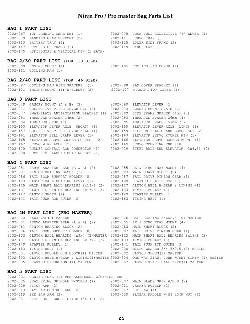
Ninja Pro / Pro master Bag Parts List
BAG 1 PART LIST2002-067 TUF LANDING GEAR SET (1) 2002-075 PUSH PULL COLLECTIVE “Y” LEVER (1)2002-079 LANDING GEAR SUPPORT (2) 2002-111 SERVO TRAY (1)2002-113 BATTERY TRAY (1) 2002-115 LOWER SIDE FRAME (2)2002-117 UPPER SIDE FRAME (2) 2002-119 GYRO PLATE (1)2002-175 HORIZONTAL & VERTICAL FIN (1 EACH)
BAG 2/30 PART LIST (FOR .30 SIZE)2002-099 ENGINE MOUNT (1) 2002-105 COOLING FAN COVER (1)2002-151 COOLING FAN (1)
BAG 2/40 PART LIST (FOR .46 SIZE)2002-097 COOLING FAN WITH SPACERS (1) 2002-098 FAN COVER BRACKET (1)2002-101 ENGINE MOUNT (1) W/SCREWS (2) 2002-107 COOLING FAN COVER (1)
BAG 3 PART LIST2002-049 CANOPY MOUNT (A & B) (3) 2002-069 ELEVATOR LEVER (1)2002-071 COLLECTIVE PITCH LEVER SET (2) 2002-073 RUDDER MOUNT PLATE (1)2002-077 SWASHPLATE ANTIROTATION BRACKET (1) 2002-089 SIDE FRAME SPACER 14mm (8)2002-091 THREADED SPACER 14mm (2) 2002-093 THREADED SPACER 26mm (4)2002-094 THREADED STUB (1) 2002-095 THREADED SPACER 57mm (1)2002-153 ELEVATOR LEVER AXLE (SHORT) (1) 2002-155 ELEVATOR LEVER AXLE (LONG) (1)2002-157 COLLECTIVE PITCH LEVER AXLE (1) 2002-159 AILERON BELL CRANK LEVER SET (2)2002-161 ELEVATOR BELL CRANK LEVER (1) 2002-163 ELEVATOR SERVO ROCKER PIN (1)2002-165 ELEVATOR SERVO ROCKER COUPLER (2) 2002-166 ELEVATOR SERVO ROCKER MOUNT (1)2002-167 SERVO WIRE LOCK (2) 2002-169 SERVO MOUNTING END (10)2002-170 RUDDER CONTROL ROD CONNECTOR (1) 2002-229 STEEL BALL END ELEVATOR (3x4.5) (2)2002-238 COMPLETE PLASTIC BEARING SET (1)
BAG 4 PART LIST2002-051 SERVO ADAPTER REAR (A & B) (2) 2002-055 RX & GYRO TRAY MOUNT (4)2002-081 PINION BEARING BLOCK (3) 2002-083 MAIN SHAFT BLOCK (2)2002-086 TAIL BOOM SUPPORT HOLDER (8) 2002-087 TAIL DRIVE PINION GEAR (1)2002-103 CLUTCH BALL BEARING 4x9x4 (1) 2002-109 STARTER BELT 500mm (1)2002-125 MAIN SHAFT BALL BEARING 8x19x6 (2) 2002-127 CLUTCH BELL W/GEAR & LINING (1)2002-131 CLUTCH & PINION BEARING 6x17x6 (3) 2002-133 TIMING PULLEY (1)2002-147 CLUTCH SHOES (1) 2002-149 STARTER PULLEY (1)2002-171 TAIL PUSH ROD GUIDE (3) 2002-183 TIMING BELT (1)
BAG 4M PART LIST (PRO MASTER)2002-022 3X6X2.5F(2) MASTER 2002-026 BALL BEARING 3X6X2.5(10) MASTER2002-051 SERVO ADAPTER REAR (A & B) (2) 2002-055 RX & GYRO TRAY MOUNT (4)2002-081 PINION BEARING BLOCK (2) 2002-083 MAIN SHAFT BLOCK (2)2002-086 TAIL BOOM SUPPORT HOLDER (8) 2002-087 TAIL DRIVE PINION GEAR (1)2002-103 CLUTCH BALL BEARING 4x9x4 (2)MASTER 2002-125 MAIN SHAFT BALL BEARING 8x19x6 (2)2002-131 CLUTCH & PINION BEARING 6x17x6 (3) 2002-133 TIMING PULLEY (1)2002-149 STARTER PULLEY (1) 2002-171 TAIL PUSH ROD GUIDE (3)2002-183 TIMING BELT (1) 2002-230 MICRO WASHER 3X4.5X0.5T(8) MASTER2002-301 CLUTCH DOUBLE B.B BLOCK(1) MASTER 2002-302 CLUTCH SHOES(1) MASTER2002-303 CLUTCH BELL W/GEAR & LINING(1)MASTER 2002-304 ONE WAY START CONE W/SET SCREW (1) MASTER2002-305 STARTER EXTENSION (1) MASTER 2002-307 CLUTCH SHAFT BALL TYPE(1) MASTER
BAG 5 PART LIST2002-001 CENTER YOKE (1) PRE-ASSEMBLED W/CENTER HUB2002-005 FEATHERING SPINDLE W/SCREW (1) 2002-007 MAIN BLADE GRIP W/B.B (2)2002-009 PITCH ARM (2) 2002-011 DAMPER RUBBER (2)2002-013 FLY BAR CONTROL ARM (2) 2002-017 SEE SAW (1)2002-019 SEE SAW ARM (2) 2002-029 FLYBAR PADDLE W/M3 LOCK NUT (2)2002-231 STEEL BALL END - PITCH (3X14 ) (2)
2 52 52 52 52 5

BAG 6 PART LIST2002-023 WASHOUT ARM (2)2002-025 RADIUS LINK (2) 2002-031 SWASHPLATE ASSEMBLY (1)2002-121 MAIN SHAFT (1) 2002-123 MAIN SHAFT STOPPER (1)2002-135 MAIN GEAR (1) W/AUTOROTATION SET (1)2002-021 WASHOUT UNIT W/ BASE A&B, WASHOUT ARMS (2) RADIUS LINK AND PINS(2) 5MM STEEL BALLS (2) 2X10MM SCREWS (2) 2MM NUTS (2) 2MM CONICALS (2) SPECIAL PIVOT SCREWS (2) 3X3 SET SCREWS (2) 4X4 SET SCREW (1)
BAG 7 PART LIST2002-185 TAIL GEAR BOX SIDE PLATE W/B.B. (2) 2002-187 TAIL GEAR BOX HOUSING (1)2002-188 TAIL GUIDE PULLEY W/B.B. (1) 2002-191 TAIL PITCH LEVER W/B.B. (1)2002-193 TAIL OUTPUT SHAFT WITH PULLEY (1) 2002-199 TAIL SHAFT HUB (1)2002-201 TAIL PITCH CONTROL PLATE (1) 2002-203 T/P INNER SLEEVE & LOCK WASHER(1)2002-204 TAIL PITCH PLATE BALL BEARING (2) 2002-205 TAIL PITCH HOUSING (1)2002-206 TAIL BLADE GRIP ASSEMBLY (2) 2002-227 TAIL ROTOR BLADE (2) W/ TAIL GRIP BB (2) SPACERS (2) 2002-202 TAIL PITCH PLATE SCREW W/PIN (2) 2X10MM SCREWS (9) 2MM NUTS (9) 5MM PIVOT BALL (2)
BAG 8 PART LIST2002-000 NINJA METRIC HARDWARE PACK (1) 2002-032 SWASHPLATE ANTIROTATION SCREW(1) W/ TEFLON SLEEVE (1) 3MM CONICALS(2)
5MM THREADED BALL (1)2002-057 STARTER BELT RETAINING CLIP (2) 2002-212 PUSH ROD COMPLETE SET (1)2002-233 BALL LINK - LONG (32) 2002-235 BALL LINK, SHORT (8)EX SMALL (2)2002-239 STEEL BALL 5mm (21)
BAG 9 PART LIST2002-063 FUEL TANK 10oz(1) W/BRASS TUBES(2)FUEL TUBE (1) FUEL CLUNK (1)
BAG 10 PART LIST2002-015 SPRING STEEL FLYBAR (1) 2002-173 TAIL BOOM (1)2002-179 TAIL BOOM SUPPORT ROD (2) 2002-223 RUSH ROD - RUDDER 476mm (1)
BAG 11 PART LIST2002-043 MAIN ROTOR BLADE (PREBUILT)(2)
BAG 12 PART LIST (Ninja Pro)2002-065 CANOPY WITHOUT MOUNT(1)
BAG 12M PART LIST (Pro Master)2002-250 CANOPY WITHOUT MOUNT(1) PRO MASTER ONLY W/ CLEAR WINDSHIELD (1)
2 62 62 62 62 6

STAMPHERE
CENTURY HELICOPTER PRODUCTS521 SINCLAIR FRONTAGE RD.
MILPITAS CA 95035
CENTURY HELICOPTER PRODUCTS
PRODUCT REGISTRATION CARD
Dear Customer:Thank you for the purchasing of this very finest quality heli-
copter kit,the Ninja Pro. Please fill out this registration card and return itto us so we can keep you informed on future enhancements.
If you would like to received a 90 minutes of our Ninja Proassembly and setup tape please also include $5.00 to cover ship-ping. (for U.S.A only)
Serial # kit pack by: kit inspect by:
Owner’s Name:
Address:
City: State: Zip:
Telephone:
Purchased From: Purchased Date:
Dealer’s Address:
City: State: Zip:
2 72 72 72 72 7

CENTURY HELICOPTER PRODUCTS521 SINCLAIR FRONTAGE RD.MILPITAS CA 95035 U.S.A
TEL: (408) 942-9525FAX: (408) 942-9524