Embed Size (px)
Citation preview

Modular Safety Gate Switches for Machine Guarding Applications
amG
ardp
roPa
rt N
umbe
r Con
figur
ator

Part No. Description
MA AM Handle
Step 1: Choose the Actuator
Part No. Description
TA AT Tongue
Act
uato
rs
Part No. Description
EI proIR Handle to allow emergency release (only to be used with I6 or I7 head).
proAM Handle proAT Tongue
Part No. Description
TK Short AT Tongue (allows padlocks through the tongue to work as a lock out tag out, but reduces over travel).
proHandle Options
Part No. Description
TI Slidebar with Internal handle but no return spring
Part No. Description
TN Slidebar without a spring
Part No. Description
EH proHandle (the red internal release handle only works with units with no locking (i.e. stops) or in conjunction with a pushIR unit).
Part No. Description
EN proHandle, no Internal Release
Part No. Description
NO No Actuator required
proSlidebar Options proRelease IR Handle
Part No. Description
TS Slidebar with a return spring
Part No. Description
TM Slidebar with Internal handle c/w TK Short Tongue
Part No. Description
TG Slidebar with Internal handle for GM
Part No. Description
TF Slidebar with Internal handle c/w spacer behind the knob
For use with ‘M’ Heads
NO Actuator Required
x
For use with ‘T’ Heads For use with ‘I’ Heads
53.5
62.5
MI, TI, TM, TG, TF and EH
work well with a pushIR unit (see step 4)
proi
Part No.
Description
MI AM Handle with Internal Release
“If no Actuator is
required go to Step 3, where you can select a Head or
Cap (C6)”
proi
Turning motion holds door closed. Ideal for non locking set ups (i.e. proSTOP devices)
Turning motion holds door closed. Internal handle allows user to open door from inside (pushIR may be required depending on application)
High strength and ease of opening makes this the most popular actuator in the amGardpro range.
Allows padlocks through the tongue to work as a lock out tag out, but reduces over-travel
Sliding motion holds door closed. With no return spring unit remains in the position it is left in
Sliding motion holds door closed. Return spring pulls the slidebar open, preventing clashes with the head (but requires the slidebar to be held forward whilst locking)
Sliding motion holds door closed. Same as a TN but IR knob allows door to be opened (but not closed) from the inside when main unit is unlocked
Sliding motion holds door closed. Short TK tongue allows padlock through tongue to act as a lock out. Additional lock out space at rear of slidebar
Sliding motion holds door closed. Short TK tongue allows padlock through tongue to act as a lock out. No additional lock out space at rear of slidebar
Handle motion holds door closed, but no method to open door from inside
The red internal release handle only works with units with no locking (i.e. Stops) or in conjunction with a pushIR unit
Handle motion holds door closed. Red handle overrides all locking mechanisms and opens safety contacts to allow escape release
Select this when you wish to specify head direction (Handing) but are not purchasing an actuator
Same as a TN but IR knob allows door to be opened and closed from the inside when main unit is locked

Step 2: Choose the HandingA
ctua
tors
Part No. Handing Description
1 Front Facing
Part No. Handing Description
2 Left Hand
Part No. Handing Description
3 Rear Facing
Part No. Handing Description
4 Right Hand
proi
Even if you have not chosen an
actuator from Step 1 you can still choose handing for the head
module
proi
If you chosen an EI Actuator from
Step 1, Front Facing,1 and Rear Facing, 3
Handing Opions are not allowed

Step 3: Choose the Head ModuleH
ead
Mod
ules
Part No. Description
C6 To terminate assemblies without heads
Part No. Description
M6 proAM Head
Part No. Description
M7 proAM Head c/w Drop Down Lockout
Part No. Description
T6 proAT Head
Part No. Description
M8 proAM Head c/w Lock-Out Clip
Part No. Description
T8 proAT Head c/w ATL Lock-Out Clip
Part No. Description
T7 proAT Head c/w Drop Down Lockout
Part No. Description
I6 proIR Head (only works in conjunction with EI handle)
proCap Options proAM Head Options proAT Head Options proRelease IR Handle Options
proi
If a head module is not required,
leave the part number blank and continue to
Step 4
For use with actuators:MAMI
For use with actuators:MAMI
For use with actuators:MAMI
For use with actuators:TA TSTK TMTI TGTN TFEH EN
For use with actuators:TA TSTK TMTI TGTN TFEH EN
For use with actuators:TA TSTK TMTI TGTN TFEH EN
For use with actuators:EI
proi
Ensure the head module you
have selected works with the actuator you
have selected in Step 1
Terminates assemblies without heads Turning motion holds door closed. Ideal for non locking set ups (i.e. proSTOP devices)
M6 head with drop down lockout. This lockout features slides into place every time actuator is removed. Ideal for applications where lockout is to be used on every entry
M6 head with drop down clip. Ideal for applications where lockout is not to be used on every entry
High strength and ease of opening makes this the most popular head in the amgard pro range
T6 head with drop down lockout. This lockout features slides into place every time actuator is removed. Ideal for applications where lockout is to be used on every entry
T6 head with drop down clip. Ideal for applications where lockout is not to be used on every entry
Part No. Description
I7 proIR Head c/w drop down lockout (only works in conjunction with EI handle)
Handle motion holds door closed. Red handle overrides all locking mechanisms and opens safety contacts to allow escape release
I6 head with drop down lockout. This lockout features slides into place every time actuator is removed. Ideal for applications where lockout is to be used on ever entry
For use with actuators:EI

Step 4: Do you want a Push IR
A PushIR will allow emergency exit even if unit is locked by keys and or solenoid. A PushIR is not needed if a EI Handle and I Head have already been specified. (note, a pull reset (R6, R7, R8 & R9) reduces the safety of the system).
Ada
ptor
s
Part No. Push IR Description
R1 Key Reset (up to 40mm panel thickness)
Part No. Push IR Description
R2 Key Reset (up to 60mm panel thickness)
Part No. Push IR Description
R3 Key Reset (up to 80mm panel thickness)
Part No. Push IR Description
R4 Key Reset (variable length - for panel thickness over 80mm and up to 1m)
Part No. Push IR Description
R6 Pull Reset (up to 40mmpanel thickness)
Part No.
Push IR Description
R7 Pull Reset (up to 60mm panel thickness)
Part No. Push IR Description
R8 Pull Reset (up to 80mm panel thickness)
Part No. Push IR Description
R9 Pull Reset (variable length for panel thickness over 80mm and up to 1m)
Part No. Push IR Description
RW Front Reset no key (up to 40mm panel thickness)
Part No. Push IR Description
RX Front Reset no key (up to 60mm panel thickness)
Part No. Push IR Description
RY Front Reset no key (up to 80mm panel thickness)
Part No. Push IR Description
RZ Front Reset no key (variable length for panel thickness over 80mm up to 1m)
proiIf a Push IR
is not required leave part number
blank and go to Step 5
Same as RW but key reset to ensure all incidents are reported
Same as RX but key reset to ensure all incidents are reported
Same as RY but key reset to ensure all incidents are reported
Same as RZ but key reset to ensure all incidents are reported
Same as RW but pull reset allows door to be relocked from the inside (requires careful risk assessment to ensure this is acceptable)
Same as RX but pull reset allows door to be relocked from the inside (requires careful risk assessment to ensure this is acceptable)
Same as RY but pull reset allows door to be relocked from the inside (requires careful risk assessment to ensure this is acceptable)
Same as RZ but pull reset allows door to be relocked from the inside (requires careful risk assessment to ensure this is acceptable)
Overrides all locking mechanisms and opens safety contacts to allow escape release. Simple push reset allows quick restart. Suitable for panels upto 40mm thick
Overrides all locking mechanisms and opens safety contacts to allow escape release. Simple push reset allows quick restart. Suitable for panels upto 60mm thick
Overrides all locking mechanisms and opens safety contacts to allow escape release. Simple push reset allows quick restart. Suitable for panels upto 80mm thick
Overrides all locking mechanisms and open safety contacts to allow escape release. SImple push reset allows quick restart. Suitable for panels upto 300mm thick

Step 5: Choose a Extracted Key ModuleA
dapt
ors Part #
Description Part No.Standard Lock L
Releasing Lock (must be used if a PushIR or EI Handle and Head used). R
E K
C
LIL & MLIL
CLIS & MLIS
If you’ve selected a pushIR adaptor
then select a releasing lock.
If you’ve selected an I6/I7 then
select a releasing lock.
or
proiIf an Extracted Key
Adaptor is not required leave part number blank and
go to Step 6
Description Information Part No.Standard Lock no dusctcover Removed key ensures door cannot be locked
until operator returns from cell with the key. Extracted version will not open door until key is removed
CLIN 1
Standard Lock with dustcover Same as EK_1 but with dustcover for dusty environments
CLIS 2
Standard Lock with padlockable dustcover
Same as EK_3 but pad lockable dustcover allows lockout feature
CLIL 3
Masterable Lock no dustcover Same as EK_1 but master lock allows a single key to override all locks (master key must be carefully controlled on site)
MLIN 6
Masterable Lock with dustcover Same as EK_2 but master lock allows a single key to override all locks (master key must be carefully controlled on site)
MLIS 7
Masterable Lock with padlockable dustcover
Same as EK_3 but master lock allows a single key to override all locks (master key must be carefully controlled on site)
MLIL 8
C
LIN & MLIN

Step 6: Choose a Safety Key AdapterA
dapt
ors
Part #
S K
Description Part No.Standard Lock L
Releasing Lock (must be used if a PushIR or EI Handle and Head used). R
Description Information Part No.Standard Lock no dusctcover Removed key ensures door cannot be locked
until operator returns from cell with the key CLIN 1
Standard Lock with dustcover Same as SK_1 but with dustcover for dusty environments
CLIS 2
Standard Lock with padlockable dustcover Same as SK_3 but pad lockable dustcover allows lockout feature
CLIL 3
Masterable Lock no dustcover Same as SK_1 but master lock allows a single key to override all locks (master key must be carefully controlled on site)
MLIN 6
Masterable Lock with dustcover Same as SK_2 but master lock allows a single key to override all locks (master key must be carefully controlled on site)
MLIS 7
Masterable Lock with padlockable dustcover Same as SK_3 but master lock allows a single key to override all locks (master key mst be carefully controlled on site)
MLIL 8
Description Part No.No. of Safety Lock Adaptors required 1 - 9
C
LIL & MLIL
CLIS & MLIS
C
LIN & MLIN
proiIf a Safety Key
Adaptor is not required leave part number blank and
go to Step 7
Total Extracted,
Safety & Access Locks in one
configuration is Max 9
proi
If you’ve selected a pushIR adaptor
then select a releasing lock.
If you’ve selected an I6/I7 then
select a releasing lock.
or

Step 7: Choose a Access Key AdapterA
dapt
ors
Part #
A K
Description Part No.Standard Lock L
Releasing Lock (must be used if a PushIR or EI Handle and Head used). R
Description Information Part No.Standard Lock no dusctcover Ensures door cannot be opened without
access key. Access key could be held by authorised individuals (e.g. maintenance) or it could have been released by a seperate unit
CLIN 1
Standard Lock with dustcover Same as AK_1 but with dustcover for dusty environments
CLIS 2
Standard Lock with padlockable dustcover Same as AK_3 but pad lockable dustcover allows lockout feature
CLIL 3
Masterable Lock no dustcover Same as AK_1 but master lock allows a single key to override all locks (master key must be carefully controlled on site)
MLIN 6
Masterable Lock with dustcover Same as AK_2 but master lock allows a single key to override all locks (master key must be carefully controlled on site)
MLIS 7
Masterable Lock with padlockable dustcover Same as AK_3 but master lock allows a single key to override all locks (master key must be carefully controlled on site)
MLIL 8
Description Part No.No. of Access Lock Adaptors required 1 - 9
C
LIL & MLIL
CLIS & MLIS
C
LIN & MLIN
proiIf an Access Key
Adaptor is not required leave part number blank and
go to Step 8
Total Extracted,
Safety & Access Locks in one
configuration is Max 9
proi
If you’ve selected a pushIR adaptor
then select a releasing lock.
If you’ve selected an I6/I7 then
select a releasing lock.
or

Step 8: Choose a Electrical Switching / Locking BodyE
lect
rical
Sw
itchi
ng /
Lock
ing
proLok Body
Part No. Description Information
SL Short Lok Body
Solenoid controlled safety switch. Holds door locked until signal sent to unlock. No provision for control buttons
SR Short Lok Body - Releasing (must be used if a pushIR or EI handle and head used).
Same as SL but allows pushIR or EI handle to override it
SE Short Lok Body - Integrated Escape Release
Same as SL but it’s integrated escape release button overrides locking mechanism and opens safety contacts (Does not work with key adaptors, EI or pushIR)
Part No. Description Information
LL Long Lok Body
Solenoid controlled safety switch. Holds door locked until signal sent to unlock. With space for control buttons
LR Long Lok Body - Releasing (must be used if a pushIR or EI handle and head used).
Same as LL but allows pushIR or EI handle to override it
LE Long Lok Body - Integrated Escape Release
Same as LL but it’s integrated escape release button overrides locking mechanism and opens safety contacts (Does not work with key adaptors, EI or pushIR)
proStop BodyproLok+ Body
Part No.
Description Information
ST Stop Body Safety switch
proStopEX/UX Body
Part No. Description Information
EX EU Explosion Stop Body
Safety switches suitable for explosive environments with EU certification
UX
US Explosion Stop Body
Safety switches suitable for explosive environments with US certification
proStop Foot
Part No. Description Information
FT
To Terminate non-switch configurations
Terminates non-switch configurations (not suitable for units with pushIR or EI handle)
If an Electrical Switching / Locking Body is not required leave part number blank and continue
to Step 10
proi
If you’ve selected a pushIR adaptor
then select a releasing lock.
If you’ve selected an I6/I7 then
select a releasing lock.
or
SE LE
SL LL

Step 9: Choose Electrical Switching / Locking Body Options
Part #
Voltage Options Part No.No Voltage (eg Foot) 0
110v 1230v 2
24v 4100v 5
48v 7Asi 8
110v Solenoid / 24v Control (LOK only) S110v Control / 24v Solenoid (LOK only) C
Override Options Part No.Stop/EXP/UXP 0
PTU - Key Override 1PTU - Knob Override 2
PTU - Screwdriver Override 3PTL (24v, 110v & ASi only) 6
Other PCB Options proBody Types Part No.Std & Sourcing ALL 1
Std & Sinking ST Only 2Std & Sourcing (3 x NC) ST Only 3
Std & Sourcing (Y&G LEDS) SL, SR, LL & LR Only 4Un-Monitored Sol & Sourcing SL, SR, LL & LR Only 6
Un-Monitored Sol & Sourcing (Y&G LEDS) SL, SR, LL & LR Only 7Individual Safety Control for Sol & Actuator SL, SR, LL, LR, SE &
LE Only 8
proiThis is ordered by 99% of our
customers

Step 10: Choose options for Separate Option Pod or proLok+ BodyO
ptio
n P
ods
Select Unit Part No.
Stand alone Pod with No holes on top of pod case (stand alone unit)
B 0
Pod with one hole on top of pod case for fitting to proStop Body
B 1
Pod with two holes on top of pod case for fitting to proLOK Body
B 2
proLok+ Body switch information L 0
Part No. Pushbuttton / Lamp Options - 24v only
0 Blank
1 Red Lamp
2 Yellow Lamp
3 Green Lamp
6 Blue Lamp
7 White Lamp
E E-Stop (twist reset)
H E-Stop (with additional monitoring contacts, twist reset)
P E-Stop (pull reset)
U E-Stop (illuminated twist reset)
L* Latching selector switch (illuminated)
M* Momentary selector switch (illuminated)
A* Latching key switch (90 degree)
R Red illuminated push button non latching
Y Yellow illuminated push button non latching
G Green illuminated push button non latching
B Blue illuminated push button non latching
W White illuminated push button non latching
K Black non illuminated push button non latching
Top
Left
Bot
tom
Rig
ht
Bot
tom
Lef
t
Top
Rig
ht
Part No. Sensors - 24v only
N No additional switch required
C Coded Magnet - Left Hand (see step 2 for handing)
D Coded Magnet - Right Hand (see step 2 for handing)
S RFID - Left Hand (see step 2 for handing)
T RFID - Right Hand (see step 2 for handing)
Separate Option Pod
proLok+ Body with 4 hole positions
Top Left
Top Right
BottomLeft
Bottom Right
Top Left
Top Right
BottomLeft
Bottom
Right
If an Option Pod or Long Lok Body
is not required leave part number blank and continue
to Step 11
proi
proLok+ Bodywith 2 hole postions
Top Left
Top Right
If you order just one or two
push buttons we will retain the order
but position them top left and
top right
proi
L, M & A Options
can only be fitted in top right or
bottom left positions
proi

Step 11: Do you want a Key Switch Option Pod?O
ptio
n P
ods
Part #
Description Part No.
CLIN Standard Lock no dustcover 1CLIS Standard Lock with dustcover 2CLIL Standard Lock with padlockable dustcover 3MLIN Masterable Lock no dustcover 6MLIS Masterable Lock with dustcover 7MLIL Masterable Lock with padlockable dustcover 8
B K
C
LIL & MLIL
CLIS & MLIS
C
LIN & MLIN
Select Unit Part No.
Stand alone Pod with No holes on top of pod case (stand alone unit)
0
Pod with one hole on top of pod case for fitting to proStop Body
1
Pod with two holes on top of pod case for fitting to proLOK Body
2
If a Key Switch Option Pod
is not required leave part number blank and continue
to Step 12
proi
Removal of the key operates a set of safety rated switches.
Common uses are: request machine stop, enable teach mode and
prevent inadvertent re-start
proi

Step 12: Selecting an ASi Option Pod
If you require e-stops, push buttons, lamps, coded magnet switch or keyswitch option pods to be ASi enabled you must select one of the options below.
Opt
ion
Pod
s
Part No. Description Control Safety Examples
BA1 ASi Option pod with Control only PCB 1 0 Option pod with illuminated red, green & yellow pushbuttons.
BA2 ASi Option pod with Safety only PCB 0 1 Option pod with e-stop or coded magnet.
BA3ASi Option pod with 1 Safety and 1 Control PCB
1 1Option pod with e-stop and red, green & yellow pushbuttons or Option pod with coded magnet and red, green & yellow pushbuttons.
BA4 ASi Option pod with 2 Safety only PCB 0 2 Option pod with e-stop and coded magnet.
BA5ASi Option pod with 1 Control and 2 Safety PCB
1 2 Option pod with e-stop and coded magnet and pushbuttons or Option pod wih e-stop and keyswitch pod.
BA6 ASi Option pod with 3 Safety only PCB 0 3 Option pod with e-stop, coded magnet,
keyswitch pod and pushbuttons.
BA7ASi Option pod with 1 Control and 3 Safety PCB
1 3 Option pod with e-stop, coded magnet, keyswitch and pushbuttons.
Key switch option pod -
if just two NC contacts are required then use a
Safety PCB. If 2NC, 2NO are required use a non
safety PCB.
proi

Step 13: Quick Disconnect Connector Options
Quick Disconnect Connector OptionsD1 D2 D3 D6 D7 D8 D9 E3 E4 F2
No. Pins 5 No. Pins 12 No. Pins 8 No. Pins 14 No. Pins 10 No. Pins 12 No. Pins 12 No. Pins 10 No. Pins 19 No. Pins 19
Max Voltage 300v Max Voltage 300v Max Voltage 60v Max Voltage 30v Max Voltage 60v Max Voltage 60v Max Voltage 300v Max Voltage 300v Max Voltage 300v Max Voltage 300v
Connector M12 Connector UN2 Connector M12 Connector M16 Connector M12 Connector M12 Connector M23 Connector UN2 Connector UN2 Connector M23
1 Brown 1 Orange 1 White A Brown 1 White 1 White 1 Brown 1 Orange 1 Violet 1 Violet
2 White 2 Blue 2 Brown C Red/Blue 2 Brown 2 Brown 2 Brown/White 2 Blue 2 Red 2 Red
3 Blue 3 White/Black 3 Green E Black 3 Green 3 Green 3 Blue 3 White/Black 3 Grey 3 Grey
4 Black 4 Red/Black 4 Yellow G Pink 4 Yellow 4 Yellow 4 White 4 Red/Black 4 Red/Blue 4 Red/Blue
5 Grey 5 Green/Black 5 Grey J Green 5 Grey 5 Grey 5 Green 5 Green/Black 5 Blue 5 Green
6 Orange/Black 6 Pink L Blue 6 Pink 6 Pink 6 Yellow 6 Orange/Black 6 Green 6 Blue
7 Blue/Black 7 Blue M Orange 7 Blue 7 Blue 7 Grey 7 Red 7 Brown 7 Grey/Pink
8 Black/White 8 Red N Grey/Brown 8 Red 8 Red 8 Pink 8 Green/Yellow 8 White/Green 8 White/Green
9 Green/Yellow O Violet 9 Orange 9 Orange 9 Red 9 Black 9 White/Yellow 9 White/Yellow
10 Red P Red 10 Tan 10 Tan 10 Black 10 White 10 White/Grey 10 White/Grey
11 White R White 11 Black 11 Violet 11 Black 11 Black
12 Black S Grey 12 Violet 12 Green/Yellow 12 Green/Yellow 12 Green/Yellow
T Yellow 13 Yellow/Brown 13 Yellow/Brown
U Tan 14 Brown/Green 14 Brown/Green
15 White 15 White
16 Yellow 16 Yellow
17 Pink 17 Pink
18 Grey/Brown 18 Grey/Brown
19 Grey/Pink 19 Brown
D1 D2 D3 D6 D7 D8 D9 E3 E4 F2

T Wiring Left Hand QD Right Hand QD
T # # # # #
Contact Fortress engineering to be assigned T Wiring number No.
Pins Connector
0 0
D 1 5 M12
D 2 12 UN2
D 3 8 M12
D 6 14 M16
D 7 10 M12
D 8 12 M12
D 9 12 M23
E 3 10 UN2
E 4 19 UN2
F 2 19 M23
Step 13: Quick Disconnect Connector Options
Image showing no connectors - 0 0
Left Hand QD
Right Hand QD
Quick Disconnect Connector OptionsD1 D2 D3 D6 D7 D8 D9 E3 E4 F2
No. Pins 5 No. Pins 12 No. Pins 8 No. Pins 14 No. Pins 10 No. Pins 12 No. Pins 12 No. Pins 10 No. Pins 19 No. Pins 19
Max Voltage 300v Max Voltage 300v Max Voltage 60v Max Voltage 30v Max Voltage 60v Max Voltage 60v Max Voltage 300v Max Voltage 300v Max Voltage 300v Max Voltage 300v
Connector M12 Connector UN2 Connector M12 Connector M16 Connector M12 Connector M12 Connector M23 Connector UN2 Connector UN2 Connector M23
1 Brown 1 Orange 1 White A Brown 1 White 1 White 1 Brown 1 Orange 1 Violet 1 Violet
2 White 2 Blue 2 Brown C Red/Blue 2 Brown 2 Brown 2 Brown/White 2 Blue 2 Red 2 Red
3 Blue 3 White/Black 3 Green E Black 3 Green 3 Green 3 Blue 3 White/Black 3 Grey 3 Grey
4 Black 4 Red/Black 4 Yellow G Pink 4 Yellow 4 Yellow 4 White 4 Red/Black 4 Red/Blue 4 Red/Blue
5 Grey 5 Green/Black 5 Grey J Green 5 Grey 5 Grey 5 Green 5 Green/Black 5 Blue 5 Green
6 Orange/Black 6 Pink L Blue 6 Pink 6 Pink 6 Yellow 6 Orange/Black 6 Green 6 Blue
7 Blue/Black 7 Blue M Orange 7 Blue 7 Blue 7 Grey 7 Red 7 Brown 7 Grey/Pink
8 Black/White 8 Red N Grey/Brown 8 Red 8 Red 8 Pink 8 Green/Yellow 8 White/Green 8 White/Green
9 Green/Yellow O Violet 9 Orange 9 Orange 9 Red 9 Black 9 White/Yellow 9 White/Yellow
10 Red P Red 10 Tan 10 Tan 10 Black 10 White 10 White/Grey 10 White/Grey
11 White R White 11 Black 11 Violet 11 Black 11 Black
12 Black S Grey 12 Violet 12 Green/Yellow 12 Green/Yellow 12 Green/Yellow
T Yellow 13 Yellow/Brown 13 Yellow/Brown
U Tan 14 Brown/Green 14 Brown/Green
15 White 15 White
16 Yellow 16 Yellow
17 Pink 17 Pink
18 Grey/Brown 18 Grey/Brown
19 Grey/Pink 19 Brown
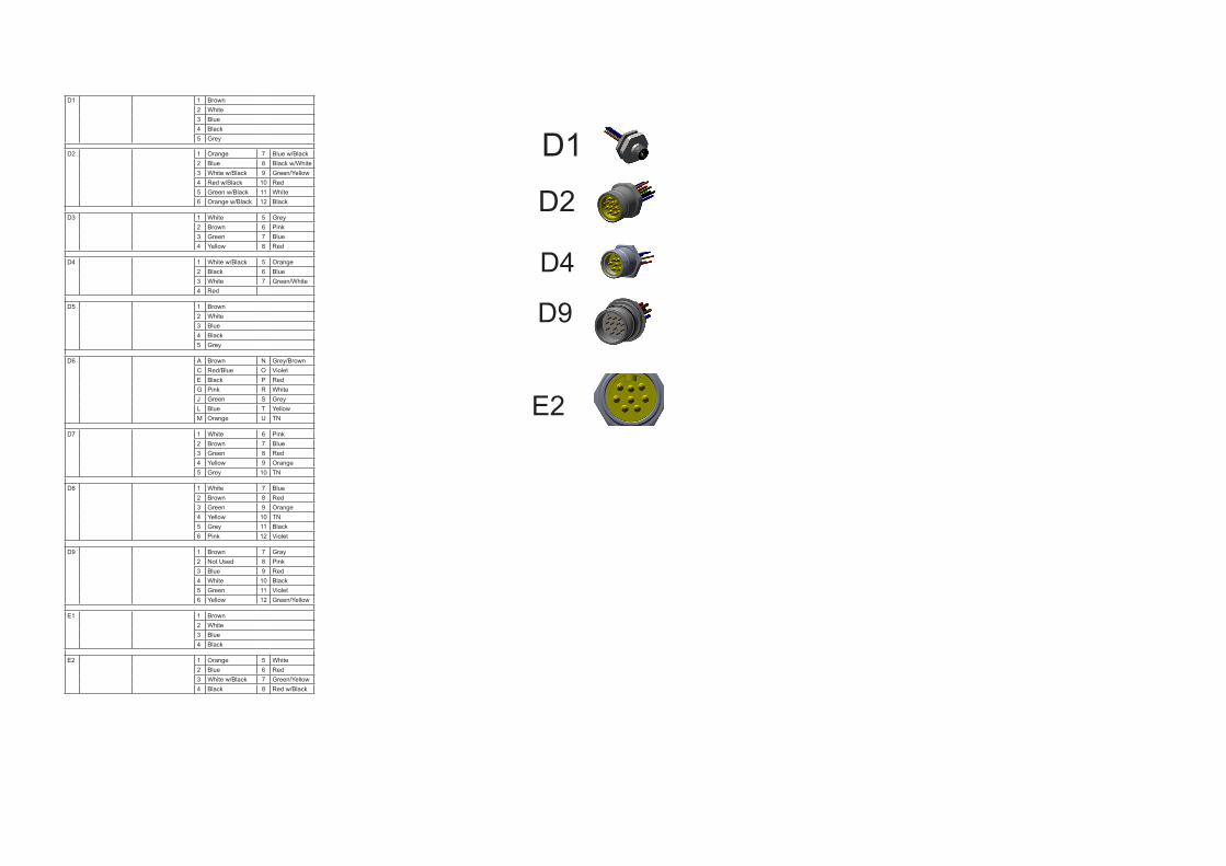
D1 1 Brown2 White3 Blue4 Black5 Grey
D2 1 Orange 7 Blue w/Black2 Blue 8 Black w/White3 White w/Black 9 Green/Yellow4 Red w/Black 10 Red5 Green w/Black 11 White6 Orange w/Black 12 Black
D3 1 White 5 Grey2 Brown 6 Pink3 Green 7 Blue4 Yellow 8 Red
D4 1 White w/Black 5 Orange2 Black 6 Blue3 White 7 Green/White4 Red
D5 1 Brown2 White3 Blue4 Black 5 Grey
D6 A Brown N Grey/BrownC Red/Blue O VioletE Black P RedG Pink R WhiteJ Green S GreyL Blue T YellowM Orange U TN
D7 1 White 6 Pink2 Brown 7 Blue3 Green 8 Red4 Yellow 9 Orange5 Grey 10 TN
D8 1 White 7 Blue2 Brown 8 Red3 Green 9 Orange4 Yellow 10 TN5 Grey 11 Black6 Pink 12 Violet
D9 1 Brown 7 Gray2 Not Used 8 Pink3 Blue 9 Red4 White 10 Black5 Green 11 Violet6 Yellow 12 Green/Yellow
E1 1 Brown2 White3 Blue4 Black
E2 1 Orange 5 White2 Blue 6 Red3 White w/Black 7 Green/Yellow4 Black 8 Red w/Black
D1
D2
D4
D9
E2