Embed Size (px)
Citation preview

1
THE CITY OF WINNIPEG PUBLIC WORKS DEPARTMENT
ENGINEERING DIVISION
PRIVATE ACCESS
Guide to Constructing
Private Approaches & Walks Revised 04.26.2021

PRIVATE ACCESS KEY POINTS
• It is the responsibility of the property owner benefitted by the
private access and the contractor constructing, removing,
relocating or modifying the private access to ensure that
construction, removal, relocation or modification complies with;
a) Private Access By-Law No. 49/2008,
b) The permit issued for the work, including any conditions
attached to the permit,
c) The Standard Construction Specifications,
d) The Manual of Temporary Traffic Control, and
e) Schedule “C” of the Private Access By-Law No. 49/2008
• The City of Winnipeg will not establish property lines or
determine the location of the private access.
• The City of Winnipeg is not responsible to notify utilities for
clearances.
• Where construction of the private access has been completed without
an inspection having been arranged, the permit holder(s) must, at no
cost to The City of Winnipeg, either demonstrate, at their own
expenses, to the satisfaction of a designated employee that the private
access meets all the requirements of The City of Winnipeg Private
Access By-law No. 49/2008 or must re-construct the private access at
their own expense
• Full depth saw cuts are required for the removal of existing curb and
gutter, partial depth saw cuts are not allowed. When saw cutting into
the existing street, it must be full depth saw cutting and must be
0.3m from the back of the curb. Cutting to the face of curb only will
not be allowed. The finishing material of the curb & gutter
replacement must match the finishing material of the street (see page
46)

PRIVATE ACCESS KEY POINTS (Cont.)
• The City of Winnipeg has approved the use of High Density
Polyethylene (HDPE) Pipe for culverts, fittings, and accessories.
Installation of Culverts (CW 3610)
o Place and compact a foundation below the proposed pipe
and bedding.
o Place and compact bedding material a minimum of 75mm
below the invert of the culvert.
o Place sand as a leveling course over the bedding material.
Sand is only to be used as a leveling course and is not to be
used as backfill.
o Clay, silt or organic soil shall not be used as bedding or
backfill material.
o Place and compact well graded granular material, in
accordance with Section 2 of CW 3110 (see page 15 & 16),
on both sides of the culvert up to the center of the pipe, then
backfill to a depth above the top of the pipe in accordance
with the manufacturer’s specifications and compact material
in 150mm lifts.
o Shape and cap the side slopes around the culvert ends with
impervious clay.
o For APPROACH CULVERT: DIAMETER, LENGTH &
ELEVATION see page 53
• Unpaid permit(s) and/or no inspection will result in any damage
deposit(s) not being released until it is proven that the approach meets
all the requirements of The City of Winnipeg Private Access By-law
No. 49/2008. This may result in the contractor’s license being put
under review and/or penalties being assessed.
• Flagperson
o Please be advised that the Province of Manitoba has
amended the Workplace Safety and Health Regulation,
Manitoba Regulation 217/2006 with the Regulation
165/2012, regarding Flagperson rules, materials, equipment
and signage. This information is available at
http://gov.mb.ca, search Regulation 165/2012.

PRIVATE ACCESS KEY POINTS (Cont.)
o Flagperson training can be provided through the
Construction Safety Association of Manitoba at
204.775.3171 and the Manitoba Heavy Construction
Association at 204.947.1379.
o The City of Winnipeg DOES NOT provide Flagperson
training.
• If a manhole is present, please call the Area Approach Inspector prior
to excavating for the approach. (see Inspector Contacts page 56)
• Concrete in approaches must be supplied by Concrete Suppliers
approved by The City of Winnipeg, see page 56 for Approved
Products Website Address.
• It shall be the Licensed Contractor’s responsibility to ensure that the
approach flares DO NOT extend beyond the projection of the
property line(s). The property lines are to be established by a
surveyor and clearly marked. Any proposed deviation from this must
be approved through email by the City Junior Technologist. Any
work completed without prior approval, will require reconstruction at
the contractor’s own expense.
• Licensed Contractor is responsible to obtain a copy of the private
access permit prior to construction of the approach.
• Only LICENSED CONTRACTORS may construct, remove,
modify or relocate a private access.
• Residential Approval/Permit requires a single application.
Commercial Private Accesses will require an application for approval
and a permit individually. Permits expire after 24 months.
• Private residential approach maximum conforming width is 6.5
metres at property line.
• Revisions have been made to City of Winnipeg Standard
Construction Specification CW 3110-R21 – Sub-grade, Sub-base and
Base Course Construction. (see pages 14-16)

PRIVATE ACCESS KEY POINTS (Cont.)
• Approval from City Forester is required if private access is within 2
metres of the outside of a tree trunk
• When constructing Private Accesses that are less than 1.5 metres
from obstructions including but not limited to; fire hydrants, hydro
poles, and communication pedestals, applicants must discuss options
with an inspector (see Fig. 27)
• Commercial and Residential approach inspections require twenty-
four (24) hours’ notice via email to the Approach Inspector to arrange
for an inspection. The City of Winnipeg will no longer accept phone
calls for approach inspections but rather an email to the
Residential/Commercial Approach Inspector will be required. Please
see contact information update (see page 56)
• A crossfall of 2-4% will be required throughout the entire approach
where proposed sidewalks will be constructed at the property line.
This applies to newly installed or proposed sidewalks in New
Developments.
• The use of caution tape or non-approved signs is an illegal violation
of the City’s Streets By-Law 1481/77 and Traffic By-Law 1573/77,
and is subject to prescribed fines. As outlined in the Manual of
Temporary Traffic Control available on the City of Winnipeg website
at
https://winnipeg.ca/publicworks/trafficControl/manualTempTraf
ficControl.stm
DISCLAIMER INFORMATION IN THIS GUIDE IS INTENDED AS A
GUIDELINE ONLY AND DOES NOT TAKE PRECEDENCE
OVER ANY CURRENT INFORMATION IN ALL OF THE BY-
LAWS AND STANDARD CONSTRUCTION SPECIFICATIONS.
The Private Access By-Law No. 49/2008 is available online @
http://clkapps.winnipeg.ca/DMIS/docext/BL_Default.asp

TABLE OF CONTENTS
DEFINITIONS _______________________________________________ 1
FREQUENTLY ASKED QUESTIONS _______________________ 2
GENERAL/SPECIFIC RULES ______________________________ 4
OTHER RULES ________________________________________ 5 APPROVALS _______________________________________________ 6
NON-CONFORMING PRIVATE APPROACHES _________________ 6 CONSTRUCTION MATERIALS _____________________________ 7
MATERIAL LAYERS ________________________________________ 7 SURFACE MATERIAL RESTRICTIONS ________________________ 8
ROADWAY TYPE ___________________________________________________ 8 CONCRETE ROADWAY: ____________________________________ 8 ASPHALT ROADWAY: ______________________________________ 8 **GRAVEL ROADWAY _____________________________________ 8
CONSTRUCTION MATERIAL ________________________________________ 8 LAYER MATERIALS ________________________________________ 9
SUBGRADE _______________________________________________________ 9 SUB-BASE ________________________________________________________ 9 BASE COURSE ____________________________________________________ 10 DRIVING SURFACES _______________________________________________ 11 MISCELLANEOUS _________________________________________________ 12
TABLES ____________________________________________________ 14
BASE COURSE AND SUB-BASE MATERIALS _________________ 14 TABLE CW 3110.1 - GRADATION REQUIREMENTS ____________ 15 TABLE CW 3110.2 - PHYSICAL PROPERTY REQUIREMENTS ___ 16 BEDDING SAND GRADING REQUIREMENTS (REF. TABLE CW
3330-R3.1) ________________________________________________ 17 ASPHALTIC CONCRETE ___________________________________ 18
COMBINED AGGREGATE GRADATION LIMITS (REF. TABLE 1 CW3410-R5.1) __ 18 PHYSICAL REQUIREMENTS (REF. TABLE 2 CW3410-R5.2) _________________ 18
DENSITIES, BOULEVARD & APPROACH SETTLEMENT _______ 19
STANDARD PROCTOR DENSITIES __________________________ 19 BOULEVARD & APPROACH SETTLEMENT _________________ 20
APPROACH DETAILS __________________________________ 21
CHART I – RESIDENTIAL / FARM ___________________________ 22 CHART II – COMMERCIAL / INDUSTRIAL ____________________ 23
FIGURE 1 _______________________________________________________ 24
FIGURE 2 _______________________________________________________ 25 FIGURE 3 _______________________________________________________ 26 FIGURE 4 _______________________________________________________ 27 FIGURE 5 _______________________________________________________ 28 FIGURE 6 _______________________________________________________ 29 FIGURE 7 _______________________________________________________ 30 FIGURE 8 _______________________________________________________ 31 FIGURE 9 _______________________________________________________ 32 FIGURE 10 ______________________________________________________ 33 FIGURE 11 ______________________________________________________ 34 FIGURE 12 ______________________________________________________ 35 FIGURE 13 ______________________________________________________ 36 FIGURE 14 ______________________________________________________ 37 FIGURE 15 ______________________________________________________ 38 FIGURE 16 ______________________________________________________ 39 FIGURE 17 ______________________________________________________ 40 FIGURE 18 ______________________________________________________ 41 FIGURE 19 ______________________________________________________ 42 FIGURE 20 ______________________________________________________ 43 FIGURE 21 ______________________________________________________ 44 FIGURE 22 ______________________________________________________ 45 FIGURE 23 ______________________________________________________ 46 FIGURE 24 ______________________________________________________ 47 FIGURE 25 ______________________________________________________ 48 FIGURE 26 ______________________________________________________ 48 FIGURE 27 ______________________________________________________ 50 FIGURE 28 ______________________________________________________ 51
GENERAL INFORMATION ____________________________________ 52
APPROVALS/PERMITS _____________________________________ 52 INSPECTIONS _____________________________________________ 52 WEATHER CONDITIONS ___________________________________ 53 APPROACH CULVERTS: DIAMETER, LENGTH & ELEVATION __ 53 RE-INSPECTION FEE _______________________________________ 53 MANHOLE & CATCH BASIN ADJUSTMENT (CW 3210 & CW 2130
OF THE CITY OF WINNIPEG STANDARD CONSTRUCTION
SPECIFICATIONS) _________________________________________ 54 APPROACH INSPECTION BOUNDARIES ______________________ 55 CONTACTS _______________________________________________ 56
1
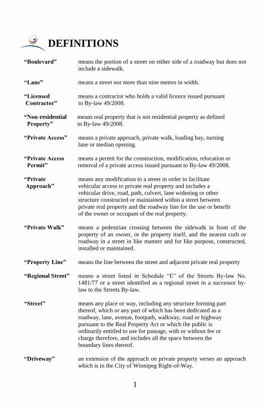
DEFINITIONS
“Boulevard” means the portion of a street on either side of a roadway but does not
include a sidewalk.
“Lane” means a street not more than nine metres in width.
“Licensed means a contractor who holds a valid licence issued pursuant
Contractor” to By-law 49/2008.
“Non-residential means real property that is not residential property as defined
Property” in By-law 49/2008.
“Private Access” means a private approach, private walk, loading bay, turning
lane or median opening.
“Private Access means a permit for the construction, modification, relocation or
Permit” removal of a private access issued pursuant to By-law 49/2008.
“Private means any modification to a street in order to facilitate
Approach” vehicular access to private real property and includes a
vehicular drive, road, path, culvert, lane widening or other
structure constructed or maintained within a street between
private real property and the roadway line for the use or benefit
of the owner or occupant of the real property.
“Private Walk” means a pedestrian crossing between the sidewalk in front of the
property of an owner, or the property itself, and the nearest curb or
roadway in a street in like manner and for like purpose, constructed,
installed or maintained.
“Property Line” means the line between the street and adjacent private real property
“Regional Street” means a street listed in Schedule “E” of the Streets By-law No.
1481/77 or a street identified as a regional street in a successor by-
law to the Streets By-law.
“Street” means any place or way, including any structure forming part
thereof, which or any part of which has been dedicated as a
roadway, lane, avenue, footpath, walkway, road or highway
pursuant to the Real Property Act or which the public is
ordinarily entitled to use for passage, with or without fee or
charge therefore, and includes all the space between the
boundary lines thereof.
“Driveway” an extension of the approach on private property verses an approach
which is in the City of Winnipeg Right-of-Way.

2
FREQUENTLY ASKED QUESTIONS
Is a Permit required to construct a private
approach or private walk, or to modify an
existing approach or walk?
Yes. In most cases an approval/permit is
required. Call Plan Approval/ Permit
Technologist at 204.986.4113.
Every owner desiring an approach or private
walk or any relocation or widening thereof must make a written application.
Applications for Residential private ap-
proaches on Non-Regional Streets must be
made at the Customer Service Branch of the
Public Work’s Customer Services counter,
107-1155 Pacific Ave.
Applications for all Commercial private ap-
proaches and Residential private approaches on Regional Streets must be made at the
Traffic Assessment Branch of the
Transportation Division, 101-1155 Pacific
Ave.
The application will be reviewed to determine
if it conforms with the Private Access By-law
No. 49/2008.
What information do I require to make an
application?
You should provide a copy of a Surveyor’s
Building Location Certificate showing the
location and dimensions of the proposed approach. As an alternative, a well-drawn
site plan showing all property dimensions,
locations of buildings and the location and dimensions of the proposed approach may be
acceptable.
For more information on
Approvals/Permits see page 52.
Approach Approval/Permit lapses 24
months after issue date.
How can I obtain a Buildings Location
Certificate?
Most home-owners already have this docu-
ment - it usually comes with the purchase of a house. A qualified Land Surveyor (see
Yellow Pages) can provide the certificate.
What if my application does not conform to
the Private Access By-law?
If the approach does not conform to the By-law you will be advised as to why the
application is non-conforming and informed
of the process to follow should you wish to
make an appeal to the applicable Community
Committee for a residential approach or to the
Standing Policy Committee for a commercial approach.
Who may construct a private access?
No person other than a licensed contractor,
the employees of a licensed contractor or a
City employee acting in the course of his or her employment may construct, remove,
modify or relocate a private access.
I have an existing approach that is no longer
required am I responsible for the cost of
removing it?
Yes, the owner is responsible for the cost of
removal of an existing private approach or
part thereof. Only where it is considered by
the City to be in the public interest to remove
an approach that is no longer required will the
cost of removing the approach be paid by the
City.
A list of licensed Private Approach
Contractors is available from:
Customer Services Branch
107-1155 Pacific Ave
Phone: 204.986.3184
Or online at:
www.winnipeg.ca/publicworks/permits
Approvals/approaches/default.stm

3
Are there City Standards that must be
followed when constructing a private
approach/walk?
Yes. One of the primary purposes of this book is to provide you with the minimum standards
that must be met. These minimum standards
in no way prevent you from constructing an approach that exceeds these standards. In fact
in certain circumstances it is recommended
that the approach design be increased.
There is a manhole in the boulevard in the
location where I wish to construct my private
approach. How will this affect my
approach?
The property owner is financially responsible for any adjustments of manhole/catch basin
(see Page 54 for details). If the approach is to
be concrete it will be necessary for you to construct an isolation (see Fig. 22).
Any valve box or curb stop adjustments can
only be done by a City Licensed
Sewer/Water Contractor. (see Contacts;
Page 56)
Be sure to read the section on Densities,
Settlement & Compaction of Boulevards &
Approaches on Page 19 & 20.
Who is responsible for repairing a Private
Approach?
The owner of the approach is responsible
for the cost of reconstruction, reinstallation,
repair, alteration or maintenance. Should a
private approach deteriorate to an unsafe
condition the City can give written notice to
the owner ordering the repairs to be done at
the owner’s cost.
Can I have my approach and driveway
widened towards the front of my home that
does not lead to a garage or side yard?
According to the Zoning by-law 200/2006, parking to the front is permitted provided it
leads to a parking space (e.g. garage or
side/rear yard).
An application must be submitted to PP&D
and Zoning for a Development permit and Variance to allow any widening in front of a
home that does not lead to a garage or
side/rear yard. The approval of the approach
will be based on whether the proper permits have been obtained, an official approval from
Zoning and PP&D for the driveway portion,
and it meets all requirements of the applicable by-laws and Standard Construction
Specifications. (see Contacts; Page 56)
The street pavement is being renewed will I
be required to pay for any necessary
alterations to my private approach?
No. The City shall assume the costs, when-
ever the City widens, reconstructs or resur-
faces a pavement and thereby necessitates
alteration or reconstruction of a lawful private
approach or walk. If the approach is not
constructed to the same standard as the
abutting street, the City may assess the cost of
improving the approach against the benefiting
property.
The City’s Waterworks crews removed a part
of my approach while carrying out a repair
to the Watermain will they be repairing the
approach?
Yes. When the City, a utility company or
others do work in a street that damages a
lawful private approach or walk the person
responsible for the damage shall assume the
entire cost of restoring the approach or walk
to its original condition. In most cases the
utility will obtain a permit to make the
excavation and will pay to the City the fees
required to do the restoration.
My approach that was inspected by the City
of Winnipeg has cracked. Is the City liable?
The City inspects the approach for design, layout and dimensions. The City was not a
part of any agreements made between the
owner and contractor or owner and supplier. It is the owner’s responsibility to ensure
that minimum standards for both
materials and construction practices are
met. These standards are discussed later
in this booklet.

4
GENERAL/SPECIFIC RULES Non-Conforming Private Accesses
“General Rules re. Private Access
17(1) Private access are non-conforming if they fail to conform to the following general
rules:
(a) the private access must not be detrimental to the safe and efficient movement of
vehicular and pedestrian traffic upon the adjacent street;
(b) subject to subsection (2), the projected nearest edge of an approach or nearest point of a
loading bay must not be within 6 metres of an intersection or an intersecting street,
measured along the property line;
(c) subject to subsection 25(5)1, an approach must not be within 30 metres of the centre line
of a railway track;
(d) two or more approaches benefiting the same assessment holding that are on the same
street must be at least 15 metres apart, measured along the property line;
(e) the nearest point of intersection between a private approach and the property line must
not be within 1.5 metres of a building or structure on the private real property.
17(2) Clause (1) (b) does not apply
(a) in the case of a private approach benefiting a residential property, where the proposed
private approach is within the projected roadway line of a roadway that has come to a dead-
end in a T-shaped intersection; and
(b) in the case of a private approach benefiting a non-residential property, when a proposed
private approach is centred within the projected roadway line of a roadway that has come to
a dead-end in a T-shaped intersection.
Specific Rules re. Residential Approaches
18. Private approaches benefiting residential properties are non-conforming if they fail to
conform to the following rules:
(a) an approach must not be less than 3 metres or greater than 6.5 metres wide measured
along the property line;

5
(b) subject to subsection 25(3)2, a private approach must not extend beyond the lot line of
the adjacent property projected into the street if
(i) the approach could negatively impact an existing or future conforming private
approach benefiting an adjacent property; and
(ii) an alternate location of the approach is possible, taking into account the proposed
or actual location of buildings on the lot;
(c) an approach must not be constructed or allowed to exist where a lane at least 4.5 metres
wide is adjacent to the property, whether or not the lane is improved.”
Notes: 1 “25(5) Notwithstanding that a private access has been approved by the City and
is otherwise in compliance with this By-law, where Transport Canada or a
railway company requires the removal, modification or relocation of the private
access as a condition of maintaining a railway crossing, it must be removed,
modified or relocated at the expense of the owner of the benefitting property.”
2 “25(3) Notwithstanding clause 18(b) and subject to subsection (4)3, in order to
accommodate an approach benefitting adjacent property, the Director may
authorize the removal or modification of that portion of a private approach that
has been permitted to extend beyond the lot line of the adjacent property projected
onto the street.”
3 “25(4) The cost of the removal or modification referred to in subsection (3) must
be borne by the owner of the property being benefitted by the approach being
constructed.”
An application that does not meet one or more of the General/Specific Rules must be
rejected by the officer for the City.
OTHER RULES
Where manholes exist, manhole isolation must be included in the construction of the
approach. (See Fig. 22)
An approach shall be constructed such that the minimum of one and a half (1.50) metres of
clearance is maintained from all obstructions. Obstructions include but not limited to; lamp
standards, hydro poles, fire hydrants and communication pedestals. (See Fig. 27) The cost
of removal or relocation or replacement of these obstructions shall be borne by the property
owner. All approaches must maintain at least two (2.0) metres clearance from the outer
edge of the trunk of a tree unless approval is granted by the City Forester.
The Private Access By-law contains a number of Schedules that restrict the construction of
approaches on:
Most main Arterial Streets that do not have service roads; and
streets where there is other means of access to the property.

6
APPROVALS
An application for a private approach or private walk which meets all of the Rules shall be
approved and an Approval/Permit issued for construction and installation, unless the City is
of the opinion that the approval of such approach or walk would be detrimental to the public
interest. Example: Property owner of a corner lot wishes to construct a private approach on
the side of the lot which is adjacent to a collector/bus route.
NON-CONFORMING PRIVATE APPROACHES
The Private Access By-law provides the property owner with a method of appealing an
application that is refused;
a) because it does not conform with one or more of the Rules,
or;
b) on the basis that it is detrimental to the public interest.
Upon application for a private approach or private walk that does not comply with the
Rules, or is determined to be detrimental to the public interest, the City will notify the
applicant why the application has been denied and outline the procedure that the applicant
can follow should the applicant wish to appeal to the designated Committee.
Where an application has been denied on the basis that it does not conform with one or
more of the Rules of the By-law, the onus shall be on the owner to satisfy the
Committee that:
i. no feasible method of providing access is possible within the terms of Rules;
ii. the approach is necessary for the intended use of the property, and;
iii. the granting of a variation of the terms of Rules will not be detrimental to the
public interest.
Where an application has been denied on the basis that it is detrimental to the public interest
the onus shall be on the City to satisfy the Committee of such detriment.
Applicants are welcome to attend Community Committee meetings, for information
regarding the process, call the Plan Approval/Permit Technologist; 204.986.4113.

7
CONSTRUCTION MATERIALS
REINFORCING STEEL
SUBGRADE
SUB-BASE
BASE COURSE
SURFACE
STEEL/PLASTIC CHAIRS
INSTALLED PRIOR TO PLACEMENT OF
CONCRETE
TIE BARS
Material Layers

8
SURFACE MATERIAL RESTRICTIONS
ROADWAY TYPE
Concrete Roadway:
(with or without asphalt overlay)
● with curb
● with asphalt or concrete
shoulders:
● with gravel shoulders
-farm or single family/ duplex
residential
-all other land uses
Asphalt Roadway:
● with curb
● with asphalt or concrete
shoulders
● with gravel shoulder:
-farm or single family/
duplex residential
-all other land uses
**Gravel Roadway
CONSTRUCTION
MATERIAL
Concrete*
Concrete*
Gravel, asphalt or concrete*
Concrete*
Asphalt or concrete*
Asphalt or concrete*
Gravel, asphalt or concrete
Asphalt or concrete*
Gravel
*- includes a surface constructed of paving stones or concrete
underlay with an asphalt overlay.
**- includes a surface constructed of oil treated gravel or chip sealant
roadways

9
LAYER MATERIALS
THE FOLLOWING ARE MINIMUM STANDARDS DERIVED FROM THE CITY OF
WINNIPEG STANDARD CONSTRUCTION SPECIFICATIONS1.
IT IS THE RESPONSIBILTY OF THE OWNER/APPLICANT/LICENSED
CONTRACTOR TO ENSURE THAT THESE STANDARDS ARE MET OR
EXCEDED.
SEE THE FOLLOWING IMPORTANT INFORMATION ON:
1) PAGE 19 FOR IMPORTANT INFORMATION ON STANDARD
PROCTOR DENSITIES
AND
2) PAGE 20 FOR IMPORTANT INFORMATION CONCERNING
BOULEVARD & APPROACH SETTLEMENT
SUBGRADE
ALL SURFACES (CW 3110)
Suitable site material Compact to a min. 95% Standard Proctor Maximum
Dry Density
Unsuitable material Replace a min. depth of 300mm with sub-base
material. See CW 3110 for acceptable sub-base
materials (see also Crushed Sub-Base Material
Grading Requirements (page 15)) and compact to
specified density.
SUB-BASE
ALL SURFACE TYPES (EXCEPT GRAVEL – Where Clay material is used)
(WHERE THERE IS UNSUITABLE SUBGRADE MATERIAL) (CW 3110)
Type See CW 3110 for acceptable materials
See also Crushed Sub-Base Material Grading
Requirements (page 15)
Min. thickness 300mm (Placed in compacted layers not exceeding
150mm)
Max. aggregate size 50mm
Gradation As specified in CW 3110
see also Crushed Sub-Base Material Grading
Requirements (page 15)
Compaction 100% Standard Proctor Maximum Dry Density
1 The City of Winnipeg Standard Construction Specifications are available in Adobe
Acrobat (PDF) format at The City of Winnipeg, Corporate Finance, Materials Management
internet site www.winnipeg.ca/matmgt/Spec/Default.stmss

10
FOR INTERLOCKING PAVING STONE (CW 3330)
FOR COMMERCIAL APPROACHES (CW 3335)
Type Lean Concrete Mix over Sub-base
Lean Mix Concrete
Min. thickness 150mm
Aggregate size 20mm nominal
Slump 25-75mm
Compressive strength 5-10 MPa @ 28 days
Air content 5-8%
Cement content 150 kg/cu.m.
Fly ash (10% of cement) 15 kg/cu.m.
FOR COMMERCIAL & RESIDENTIAL APPROACHES (CW 3330)
Type Granular B or C
Min. thickness 300mm (placed in two 150mm layers)
Max. aggregate size 50mm
Gradation well graded
Compaction 100% Standard Proctor Density
BASE COURSE
FOR CONCRETE (CW 3110)
Types See CW 3110 for acceptable base course materials (see also
Base Course Material Grading Requirements (page 15))
(Granular B2 - 25mm nominal, Granular C – 20mm nominal)
Compaction 100% Standard Proctor Maximum Dry Density
Min. thickness 75mm
FOR PAVING STONES (CW 3330)
Types Concrete Sand, Conforms to CAN3-123 Section 5, see CW
3330.
See also Bedding Sand Grading Requirements (page 17)
Min. thickness 30mm without lean mix
15mm with lean mix
FOR ASPHALT (CW 3410)
Types See CW 3110 & CW 3410 for acceptable base course
materials (See also Base Course Material Grading
Requirements (page 15))
(Granular B2 - 25mm nominal, Granular C – 20mm nominal)
Compaction 100% Standard Proctor Density
Min. thickness 200mm Residential (placed in two 100 mm layers)
300mm Commercial (100mm Base Course + 200mm Sub-
base – 50mm nominal)
2 Refer to Base Course Material Grading Requirements (page 15) for more information

11
DRIVING SURFACES
CONCRETE (CW 3310)
Note: All concrete placed must be supplied by an Approved Concrete Supplier. A list
of these suppliers is made available on the City of Winnipeg Website @
www.winnipeg.ca/matmgt/Spec/Default.stm. Select → Approved Concrete Mix Designs →
Contents
CEMENT Type 10 Normal Portland, Conforms to CSA A5
FOR RESIDENTIAL APPROACHES (CW 3310)
Min. thickness 150mm
Min. compressive strength 30 MPa @ 28 DAYS
Min. cement content 300 kg/cu.m.
Max water/cement ratio 0.49
Slump 80 +/- 20mm
Aggregate size 20mm nominal
Air content 5.0 - 8.0%
FOR COMMERCIAL APPROACHES (CW 3310)
Min. thickness 200mm
Min. compressive strength 32 MPa @ 28 DAYS
Min. cement content 340 kg/cu.m.
Max. water/cement ratio 0.45
Slump 70 +/- 20mm
Aggregate size 20mm nominal
Air content 5.0 - 8.0%
REINFORCING STEEL (Fig. 24 & 26) (CW 3310)
Type A 12.7mm plain bars, grade 300, conforms to CSA
G30.12.
Type B 10M (Deformed), grade 300, conforms to CSA
G30.12.
Placement Maintain a 75mm clearance from edges. Elevate to
mid depth of the concrete using steel/plastic
chairs sufficiently placed to ensure positioning is
maintained during concrete placement.
RESIDENTIAL APPROACH REINFORCING STEEL (SD-237 & FIG. 24)
Alternative 1 Place in a grid to form a mat. Spaced not greater
than 470mm O.C. in both directions, and welded or
securely fastened at intersections. (Ref. FIG. 26)
Alternative 2 Cut and place to form a grid spaced not greater than
400mm O.C. in both directions and welded or
securely fastened at intersections.
COMMERCIAL APPROACH REINFORCING STEEL (SD-217 & FIG. 26)
Bar Mats are to be used in accordance with SD-217, FIG. 26 and
ALTERNATIVE 1, SECTION A-A of SD-237, FIG. 24

12
PAVING STONES (CW 3330)
Type Conforms with CAN3-A231.2 Pre-cast Concrete Pavers
Placement Paving stones to be compacted into the sand bedding with a
vibratory compactor & filler sand shall be swept into the
joints until full.
ASPHALTIC CONCRETE (CW 3410)
See:
Combined Aggregate Gradation Limits (page 18)
Physical Requirements (page 18)
FOR RESIDENTIAL APPROACHES Type IA, or Type I
Minimum thickness 75mm
FOR COMMERCIAL APPROACHES Type IA
Minimum thickness 75mm
OVERLAY FOR CONCRETE Type II Minimum thickness
20mm
GRAVEL (CW 3150)
Base Course Material see Base Course Material Grading Requirements
Granular B or C
(page 15)
MISCELLANEOUS
CONCRETE INCIDENTAL ITEMS (CW 3310)
Expansion/Isolation Joint Fibre joint filler conforms to ASTM D1751, 15mm
thick, pre-formed, rot-proof, bituminous fibre.
Plastic expansion joint filler, fluted polypropylene
type 6mm in thickness.
Contraction Joint Saw cut 40mm deep X 10mm wide, located as
shown on drawing SD-211A
Tie Bars Grade 300
(Approach to pavement) – 15M (Residential) / 20M
(Commercial) deformed epoxy coated bars, 600mm
long, placed 600mm O.C., drilled into existing
pavement 230mm and bonded.
(Curb Ramps) – 15M (Residential) / 20M
(Commercial) deformed epoxy coated bars, 600mm
long, placed 600mm O.C.
Dowel Adhesive Conforms to ASTM C881, Type 1 grade 3 epoxy,
see “Approved Products Surface Works” in
Standard Construction Specifications.
Curing Compound Conforms to ASTM C309 Type 2 white pigmented,
water based liquid membrane-forming.
CAST IN PLACE CONCRETE CURBS
FOR ASPHALT/PAVING STONE APPROACHES (CW 3310)

13
Size 100mm Wide X 200mm Deep
Cement Type GU, conforms to CSA A3001
Min. compressive strength 32 MPA @ 28 DAYS
Min. cement content 340 kg/cu.m.
Max. water/cement ratio 0.45
Max. slump 70 +/- 20mm
Aggregate size 20mm nominal
Air content 5-8%
Reinforcing steel Conforms to CSA G30-12 Billet Steel for
reinforcement, 2-15M deformed bars spaced as
shown on applicable figures.
PLASTIC PAVER EDGE SUPPORT
FOR PAVING STONE APPROACHES (CW 3330)
Plastic paver edge support shall be made of High Density Polyethylene (HDPE)
material.
Plastic paver edge support may be installed as a paving stone edging for
residential approaches. All installation shall be in accordance with the
manufacturer’s instructions.
For vehicular applications 10” or 12” x 3/8” diameter steel spikes shall be spaced
every 12” (min. every 3rd hole) with the exception of radius applications, where
the steel spikes should be spaced every 8” to 12”.
An acceptable plastic edge support is “Snap Edge” as manufactured by Snapedge
Canada Ltd. or Snap Edge Corporation.
www.snapedge.ca
CULVERTS
FOR STREETS WITH DITCH TYPE DRAINAGE (CW 3610)
Size: Diameter To be determined by the City of Winnipeg,
Water & Waste Department, Engineering
Division, Land Drainage and Flood Protection
Technologist at 204.986.3670.
Length Contractor to calculate culvert length based on
approved approach width, shoulder widths and
a minimum 4:1 (rise over run) ditch slope.
Type Corrugated Steel Pipe, conforms to CSA CAN3-
G401, pre-cast concrete pipe, conforms to ASTM
C-14, C-76, or C-655, High Density Polyethylene
(HDPE) Pipe, conforms to CSA B182.8 and ASTM
D2412.

14
TABLES
Base Course and Sub-Base Materials
Granular A – open-graded virgin (not recycled) aggregates intended for use as free
draining base and sub-base within the pavement structure of high traffic volume streets (i.e.
expressways, major arterials, minor arterials, industrial/commercial collectors, residential
major collectors, residential minor collectors, and industrial/commercial locals), including
associated approaches.
Granular B – well-graded virgin or recycled aggregates intended for use as base and sub-
base within the pavement structure of low traffic volume streets (i.e. residential locals and
public lanes), including associated approaches. Granular A can be used instead of Granular
B.
Granular C – dense graded virgin or recycled aggregates intended for use as base and sub-
base for street pavement rehabilitations and other applications. Granular A or B can be used
instead of Granular C.
Crushed Recycled Concrete – aggregates obtained by recycling clean, hard, concrete
waste with maximum lightweight material/asphalt content of 8%, maximum clay content of
3% and maximum other foreign or deleterious materials content of 3%. All types of
contaminants, such as dirt, plaster, gypsum and other building waste, must be removed.
Deleterious Material – soft material that would decay or disintegrate from weathering,
porcelain, vegetation, organic material, wood, glass, plastic, metal, reinforcing steel,
building rubble, brick, shale, and friable particles.
Base Course and sub-base materials shall conform to the following requirements:
a) Base course and sub-base materials will be of a type approved by the Contract
Administrator.
b) Base course and sub-base materials shall be sound, durable particles produced by
crushing, screening, and grading of recovered materials.
c) Base course and sub-base materials shall conform to the grading requirements in
Table CW 3110.1 and the physical requirements in Table CW 3110.2
Note: All aggregate material placed must be supplied by an Approved Aggregate
Supplier. Effective July 1st, 2020, the City of Winnipeg, Research and Standards Engineer
will maintain a list of approved aggregate suppliers. A list of these suppliers is made
available on the City of Winnipeg Website @ www.winnipeg.ca/matmgt/Spec/Default.stm.

15
TABLE CW 3110.1 - Gradation Requirements P
erc
en
t O
f T
ota
l D
ry W
eig
ht
Pa
ssin
g E
ac
h S
ieve
Gra
nu
lar
C**
100
mm
100%
97%
- 1
00%
--
--
--
30%
- 5
0%
--
--
--
--
--
--
--
0%
- 8
%
50 m
m
100%
--
--
--
--
25%
- 6
0%
--
--
--
--
4%
- 1
5%
Base
Cours
e
100%
--
40%
- 7
0%
25%
- 6
0%
--
--
8%
- 2
5%
6%
- 1
7%
Gra
nu
lar
B**
100
mm
100%
85%
- 1
00%
--
50%
- 8
0%
--
30%
- 6
0%
--
20%
- 4
5%
--
--
8%
- 2
5%
--
4%
- 1
5%
2%
- 8
%
50 m
m
100%
75%
- 9
5%
55%
- 8
5%
--
30%
- 6
5%
--
--
12%
- 3
8%
--
5%
- 2
2%
2%
- 8
%
Base
Cours
e
100%
85%
- 9
5%
50%
- 7
8%
--
20%
- 4
8%
--
8%
- 2
8%
5%
- 2
0%
2%
- 8
%
Gra
nu
lar
A*
100
mm
100%
85%
- 1
00%
70%
- 9
2%
50%
- 7
5%
--
25%
- 5
5%
--
15%
- 4
0%
--
--
6%
- 2
2%
--
3%
- 1
4%
2%
- 8
%
50 m
m
100%
75%
- 9
5%
50%
- 8
4%
--
25%
- 6
0%
18%
- 4
8%
--
10%
- 3
2%
--
5%
- 2
0%
2%
- 8
%
Base
Cours
e
100%
85%
- 9
5%
50%
- 7
8%
35%
- 6
0%
20%
- 4
8%
12%
- 3
4%
8%
- 2
6%
5%
- 1
8%
2%
- 8
%
Can
ad
ian
Metr
ic S
ieve
Siz
e
125
00
0
100
00
0
75 0
00
50
00
0
37
50
0
25
00
0
20
00
0
10
00
0
5
00
0
2
50
0
1
25
0
630
315
80

16
TABLE CW 3110.2 - Physical Property Requirements G
ran
ula
r C
100
mm
--
--
--
--
20
--
25
6
15%
asph
alt m
ate
rial
3%
cla
y
3%
dele
terio
us m
ate
rials
50 m
m
--
--
--
--
20
--
25
6
Base
Cours
e
--
--
--
--
20
--
25
6
Gra
nu
lar
B 1
00
mm
35
--
--
--
17
60
25
6
10%
asph
alt m
ate
rial
3%
cla
y
3%
dele
terio
us m
ate
rials
50 m
m
--
35
--
60
17
70
22
4
Base
Cours
e
--
--
35
60
17
70
22
Non
pla
stic
Gra
nu
lar
A 1
00
mm
35
--
--
--
15
70
22
Non
pla
stic
--
50 m
m
--
35
--
80
15
80
22
Non
pla
stic
Base
Cours
e
--
--
35
80
15
80
20
Non
pla
stic
Te
sti
ng
Meth
od
AS
TM
C535
(Gra
din
g 1
)
AS
TM
C131
(Gra
din
g A
)
AS
TM
C131
(Gra
din
g B
)
AS
TM
D18
83
AS
TM
D69
28
AS
TM
D58
21
AS
TM
D43
18
Mass %
Te
sts
Los A
ngele
s A
bra
sio
n,
% m
axim
um
Los A
ngele
s A
bra
sio
n,
% m
axim
um
Los A
ngele
s A
bra
sio
n,
% m
axim
um
Calif
orn
ia B
earing R
atio
(CB
R)*
- 4
days s
oaked,
% m
inim
um
@ 2
.54 m
m
Mic
ro-D
eval A
bra
sio
n,
% m
axim
um
Perc
enta
ge o
f
Fra
ctu
red P
art
icle
s,
min
imum
tw
o o
r m
ore
fractu
red faces, %
mass**
Liq
uid
Lim
it,%
maxim
um
**
Pla
sticity I
nd
ex,%
maxim
um
**
Conte
nt
Co
mp
ositio
n,
maxim
um
**
*CBR test shall be performed at 100 % maximum dry unit weight and optimum water content. A
shorter immersion period (24 hr) is permissible for virgin aggregates that take up moisture readily if tests show that the shorter period will not affect the results.
**Percentage of Fractured Particles, Atterberg Limits, and Content Composition are not required for
crushed limestone materials. Content Composition shall be performed on materials retained on 5000 μm sieve and above.
17
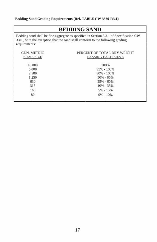
Bedding Sand Grading Requirements (Ref. TABLE CW 3330-R3.1)
BEDDING SAND Bedding sand shall be fine aggregate as specified in Section 5.3.1 of Specification CW
3310, with the exception that the sand shall conform to the following grading
requirements:
CDN. METRIC PERCENT OF TOTAL DRY WEIGHT
SIEVE SIZE PASSING EACH SIEVE
10 000 100%
5 000 95% - 100%
2 500 80% - 100%
1 250 50% - 85%
630 25% - 60%
315 10% - 35%
160 5% - 15%
80 0% - 10%

18
ASPHALTIC CONCRETE
COMBINED AGGREGATE GRADATION LIMITS (REF. TABLE 1 CW3410-R5.1)
PHYSICAL REQUIREMENTS (REF. TABLE 2 CW3410-R5.2)
CO
MB
INE
D A
GG
RE
GA
TE
GR
AD
AT
ION
LIM
ITS
Perc
ent of T
ota
l D
ry W
eig
ht P
assin
g E
ach S
ieve
Ty
pe III
(Base C
ou
rse)
%
100%
90%
to 1
00%
60%
to 9
0%
56%
to 8
0%
--
29%
to 5
9%
20%
to 5
0%
--
15%
to 3
0%
5%
to 1
7%
--
1%
to 7
%
60%
min
.
(2 f
ractu
red f
aces)
P
HY
SIC
AL
RE
QU
IRE
ME
NT
S
Ty
pe III
(Base C
ou
rse)
%
4.0
% t
o 5
.5%
12.0
% m
in.
2.5
% t
o 5
.0%
5 m
in.
6.0
to 1
6.0
Ty
pe II
(Su
rface C
ou
rse)
%
100%
90%
to 9
5%
74%
to 8
0%
55%
to 6
4%
35%
to 4
6%
22%
to 3
0%
--
8%
to 1
1%
--
Ty
pe II
(Su
rface C
ou
rse)
%
5.0
% t
o 7
.0%
16.0
% m
in.
2.5
% t
o 5
.0%
4 m
in.
6.0
to 1
6.0
Ty
pe I
(Su
rface C
ou
rse)
%
100%
--
70%
to 8
5%
45%
to 7
0%
25%
to 5
5%
20%
to 4
0%
15%
to 3
0%
5%
to 2
0%
--
3%
to 6
%
50%
min
.
(1 f
ractu
red f
ace)
Ty
pe I
(Su
rface C
ou
rse)
%
5.0
% t
o 6
.0%
14.5
% m
in.
2.5
% t
o 5
.0%
5 m
in.
6.0
to 1
6.0
Ty
pe 1
A
(Su
rface C
ou
rse)
%
99%
to 1
00%
--
70%
to 8
8%
55%
to 7
0%
40%
to 6
0%
25%
to 5
0%
15%
to 4
0%
5%
to 2
8%
4%
to 1
1%
3%
to 7
%
60%
min
.
(2 f
ractu
red f
aces)
Ty
pe 1
A
(Su
rface C
ou
rse)
%
5.0
% t
o 6
.0%
14.0
% m
in.
3.0
% t
o 5
.0%
7 m
in.
6.0
to 1
6.0
Can
ad
ian
Me
tric
Sie
ve S
ize
40 0
00
25 0
00
16 0
00
12 5
00
10 0
00
5 0
00
2 5
00
1 2
50
6
30
3
15
1
60
8
0
Cru
sh C
ount:
(Cla
use 5
.4.1
(b)
(iii)
Ta
ble
2
CW
3410-R
5.2
Asphalt C
em
ent, %
tota
l sam
ple
weig
ht
Void
s in M
inera
l A
ggre
gate
, V
MA
Air V
oid
s
Ma
rshall
Sta
bili
ty, kN
at
60°C
Flo
w I
ndex, units o
f 250 µ
m

19
DENSITIES, BOULEVARD &
APPROACH SETTLEMENT
STANDARD PROCTOR DENSITIES
Standard Proctor Densities are a measure of soils
density obtained using industry standard tests. The
Standard Proctor Density for a soil is unique to
that soil type. A sandy soil compacted to 100%
Standard Proctor Density would not be as dense
as a soil with a greater clay content compacted to
the same 100% Standard Proctor Density.
Engineering consultants can determine soil
densities and compaction (percent of Standard
Proctor Density) at a cost.
A general rule of thumb can be applied to most
soils to determine the approximate degree of
compaction. A simple procedure is to try to
penetrate the compacted soil with a common
screwdriver. The screwdriver blade should be
placed in contact with the soil and then hand force
applied to the screwdriver to penetrate the soil.
For Suitable Site sub-grade materials compacted
to 95% Standard Proctor Density it should take
considerable force to make the screwdriver
penetrate the soil 50-75mm. For a base course
material compacted to 100% Standard Proctor
Density the screwdriver should only penetrate the
soil approximately 25mm.

20
BOULEVARD & APPROACH SETTLEMENT
Water, sewer and other utility trenches exist in
most boulevards in the City of Winnipeg. Long
term settlement of the trench backfill material
can occur even though steps have been taken
during the utility installation to ensure that
compaction of the backfill material was in
accordance with Standard Construction
Specifications.
Over time boulevard and approach settlement can
occur that might adversely affect a private
approach. It is therefore recommended that the
sub-grade material in the boulevard and under the
approach be examined and preventative measures
such as sub-grade compaction by jetting and
flooding or proper mechanical means and
methods be performed prior to constructing a
private approach.
Special attention should be given to sewer
manholes and catch basins that will lie within the
limits of an approach. Backfill around manholes
may be more susceptible to settlement. Where a
manhole or catch basin exists, manhole and
catch basin isolations must be included in the
construction of the approach. A manhole or
catch basin which is not isolated will act as a pile
under the approach which can lead to serious
undermining followed by high severity cracking
of the approach when settlement ultimately does
occur.
Property owners/licensed contractors should
also consider design alternatives above the
minimum standards to minimize the effect of
long term trench and approach settlement.

21
APPROACH DETAILS
TO USE THE DETAIL CHARTS (PAGES 22 & 23) TO DETERMINE WHICH
APPROACH DETAIL IS APPLICABLE. FOLLOW THESE STEPS:
STEP 1 Determine your land usage:
-for Residential or Farm property use Chart I.
-for Commercial, Industrial or any other property use Chart II.
STEP 2 Verify:
a) The type of pavement of the Street to which the approach
will access:
-Concrete or Asphalt over Concrete,
-Asphalt, or
-Gravel
b) The type of curb if any:
-Barrier (rectangular with a vertical face)
-Lip (rolled with a diagonal face)
c) The shoulder type if applicable:
-Asphalt, or
-Gravel
Use the information from a, b & c, starting from the left to select the
proper row.
STEP 3 Determine whether the Street to which the approach will access is
considered Regional or Non-Regional. (see definitions for Regional
Streets (page 1))
Use this information to select the appropriate side of the table.
STEP 4 In the row you selected in step 2, on the side you select in step 3, locate
the cell containing the surface material type you intend to use.
Note: The listed types are the option available to conform to the Private
Access By-law.
The figure number in this cell will reference the applicable detail.

22
CH
AR
T I
– R
ES
IDE
NT
IAL
/ F
AR
M
CO
NC
RETE O
R
AS
PH
ALT O
VER
CO
NC
RETE
GRAVEL
NO
NE
NO
NE
GRAVEL
AS
PH
ALT
GR
AV
EL
PA
VEM
EN
T
TY
PE
BARRIE
R C
URB
LIP
CURB
NO
NE
NO
NE
NO
NE
ASPHALT
GRAVEL /
NO
NE
SH
OU
LD
ER
TY
PE
CU
RB
TY
PE
NO
NE
BARRIE
R C
URB
LIP
CURB
NO
NE
FIG
. 17
FIG
. 17
FIG
. 18
NO
NE
NO
NE
ASPHALT
FIG
. 18
LA
ND
US
E
REG
ION
AL
STR
EETS
NO
N-R
EG
ION
AL
STR
EETS
RES
IDEN
TIA
L /
FA
RM
GRAVEL
FIG
. 15
FIG
. 16
FIG
. 15
FIG
. 16
GRAVEL
ASPHALT
CO
NCRETE
PAVIN
G S
TO
NES
FIG
. 20
FIG
. 13
FIG
. 14
ASPHALT
CO
NCRETE
PAVIN
G S
TO
NES
FIG
. 19
FIG
. 11
FIG
. 12
ASPHALT
CO
NCRETE
PAVIN
G S
TO
NES
FIG
. 17
FIG
. 18
FIG
. 15
FIG
. 16
ASPHALT
CO
NCRETE
PAVIN
G S
TO
NES
CO
NCRETE
PAVIN
G S
TO
NES
FIG
. 15
FIG
. 16
GRAVEL
ASPHALT
CO
NCRETE
PAVIN
G S
TO
NES
GRAVEL
FIG
. 10
CO
NCRETE
PAVIN
G S
TO
NES
FIG
. 11
FIG
. 12
CO
NCRETE
PAVIN
G S
TO
NES
FIG
. 13
FIG
. 14
GRAVEL
ASPHALT
CO
NCRETE
PAVIN
G S
TO
NES
FIG
. 10
FIG
. 9
FIG
. 5
FIG
. 6
ASPHALT
CO
NCRETE
PAVIN
G S
TO
NES
FIG
. 9
FIG
. 5
FIG
. 6
ASPHALT
CO
NCRETE
PAVIN
G S
TO
NES
FIG
. 8
FIG
. 3
FIG
. 4
PAVIN
G S
TO
NES
FIG
. 2
PAVIN
G S
TO
NES
FIG
. 4
PAVIN
G S
TO
NES
FIG
. 6
CO
NCRETE
FIG
. 5
FIG
. 3
CO
NCRETE
FIG
. 1
CO
NCRETE
GRAVEL
ASPHALT
CO
NCRETE
PAVIN
G S
TO
NES
FIG
. 10
FIG
. 9
FIG
. 5
FIG
. 6
ASPHALT
CO
NCRETE
PAVIN
G S
TO
NES
FIG
. 7
FIG
. 1
FIG
. 2

23
CH
AR
T I
I – C
OM
ME
RC
IAL
/ I
ND
US
TR
IAL
FIG
. 5
FIG
. 6
ASPHALT
CO
NCRETE
PAVIN
G S
TO
NES
FIG
. 9
FIG
. 5
FIG
. 6
CO
NCRETE
PAVIN
G S
TO
NES
PAVIN
G S
TO
NES
ASPHALT
CO
NCRETE
PAVIN
G S
TO
NES
FIG
. 3
FIG
. 4
PAVIN
G S
TO
NES
CO
NCRETE
PAVIN
G S
TO
NES
FIG
. 5
FIG
. 6
CO
NCRETE
PAVIN
G S
TO
NES
FIG
. 5
FIG
. 6
GR
AV
EL
NO
NE
GRAVEL /
NO
NE
GRAVEL
GRAVEL
FIG
. 10
FIG
. 10
FIG
. 9
FIG
. 5
FIG
. 6
FIG
. 9
FIG
. 5
FIG
. 6
CO
NCRETE
FIG
. 8
FIG
. 3
FIG
. 4
FIG
. 8
NO
NE
GRAVEL
ASPHALT
FIG
. 9
NO
NE
FIG
. 2
CO
NCRETE
PAVIN
G S
TO
NES
ASPHALT
CO
NCRETE
PAVIN
G S
TO
NES
ASPHALT
CO
NCRETE
ASPHALT
NO
NE
ASPHALT
PAVIN
G S
TO
NES
FIG
. 7
FIG
. 1
FIG
. 2
FIG
. 7
FIG
. 1
ASPHALT
NO
NE
GRAVEL
PAVIN
G S
TO
NES
CO
NCRETE
AS
PH
ALT
BARRIE
R C
URB
NO
NE
ASPHALT
LIP
CURB
CO
NCRETE
PAVIN
G S
TO
NES
FIG
. 5
FIG
. 6
FIG
. 5
FIG
. 6
PAVIN
G S
TO
NES
CO
NCRETE
PAVIN
G S
TO
NES
FIG
. 3
FIG
. 4
FIG
. 3
FIG
. 4
PAVIN
G S
TO
NES
CO
NCRETE
PAVIN
G S
TO
NES
FIG
. 1
FIG
. 2
FIG
. 1
FIG
. 2
CO
NC
RETE O
R
AS
PH
ALT O
VER
CO
NC
RETE
BARRIE
R C
URB
NO
NE
CO
NCRETE
LIP
CURB
NO
NE
CO
NCRETE
NO
NE
ASPHALT
CO
NCRETE
REG
ION
AL
NO
N-R
EG
ION
AL
STR
EETS
STR
EETS
LA
ND
US
E
CO
MM
ER
CIA
L /
IN
DU
STR
IAL
PA
VEM
EN
T
TY
PE
CU
RB
TY
PE
SH
OU
LD
ER
TY
PE

24
N.T.S.
DRIVEWAY
15mm EXPANSION JOINT PROPERTY LINE (STREET LINE)
EXISTING SIDEWALK SHALL BE REMOVED AND
THE APPROACH AND EXPANSION JOINT EXTENDED
BACK TO THE PROPERTY LINE
MINIMUM PAVED WIDTH
3m RESIDENTIAL4m COMMERCIAL
CURB TAPERED TO
EXISTING OR PROPOSED
SIDEWALK RAMP AT < 5% (FIG 21)
CONTRACTION JOINT AS REQUIRED TOMATCH STREET TRANSVERSE
EXISTING OR
PROPOSED
SIDEWALK
BOULEVARD
R=4.5m MIN.
CAST-IN-PLACE MODIFIED
BARRIER CURB
BUTT JOINT
(SAW CUT AND REMOVE BARRIER
CURB AND UNDERLYING PAVEMENT)
CR
OS
SF
AL
L
MIN
=2
% M
AX
=8%
MIN
=2
% M
AX
=4%
CR
OS
SF
AL
L
PLAN VIEW
FOR COMMERCIAL APPROACHES ONNON-REGIONAL STREETS WITH CURB >80mm SEE FIG. 23
0.9m
CURB TRANSITION(TYPICAL)
0.3m
PL
1.5m SIDEWALK
TAPER CURB TO
RAMP CURB
LP
CONCRETE APPROACH THICKNESSRESIDENTIAL=150mmCOMMERCIAL=200mm OR MATCH EXISTING PAVEMENT
EXISTING CONCRETE /
ASPHALT PAVEMENT
15M DEFORMED TIE BARS600mm LONG @ 600mm O.C.(FOR CONCRETE STREETS ONLY)
75mm BASE COURSE
SUBGRADEAPPROACH LENGTH VARIES
LONGITUDINAL SECTION
NOTE
BAR MAT (SEE "REINFORCING STEEL" FIG. 24 & 25)
1) SEE FIG. 22 FOR MANHOLE ISOLATION DETAIL IF REQUIRED.
2) WHEN REPLACING THE CONNECTING SIDEWALK AT AN APPROACH, THE SIDEWALK
MUST MAINTAIN A 5% GRADE OR LESS (EXTRA PANELS MAY NEED TO BE REMOVED).
3) A CROSSFALL OF 2-4% WILL BE REQUIRED THROUGHOUT THE ENTIRE APPROACH
WHERE PROPOSED SIDEWALKS WILL BE CONSTRUCTED AT THE PROPERTY LINE. THIS
APPLIES TO NEWLY INSTALLED OR PROPOSED SIDEWALKS IN NEW DEVELOPMENTS.
*SE
E N
OT
E
JOINTS AS PER SD-211A
FIGURE 1
COMMERCIAL CONCRETE APPROACH ON REGIONAL AND NON-REGIONAL STREETS WITH BARRIER CURB
& RESIDENTIAL CONCRETE APPROACH ON REGIONAL STREETS WITH BARRIER CURB

25
N.T.S.
FOR COMMERCIAL APPROACHESON NON-REGIONAL STREETS
SEE FIG. 23WITH CURB >80mm
DRIVEWAY
PROPERTY LINE (STREET LINE)
EXISTING SIDEWALK SHALL BE REMOVED AND
THE APPROACH AND EXPANSION JOINT EXTENDED
BACK TO THE PROPERTY LINE
MINIMUM PAVED WIDTH
3m RESIDENTIAL4m COMMERCIAL
CURB TAPERED TO
EXISTING OR PROPOSED
SIDEWALK RAMP AT < 5% (FIG. 21)
EXISTING OR
PROPOSED
SIDEWALK
BOULEVARD
R=4.5m MIN.
CAST-IN-PLACE MODIFIED
BARRIER CURB
BUTT JOINT
(SAW CUT AND REMOVE BARRIER
CURB AND UNDERLYING PAVEMENT)
CR
OS
SF
AL
L
MIN
=2
% M
AX
=8
%M
IN=
2%
MA
X=
4%
CR
OS
SF
AL
L
PLAN VIEW
0.9m
CURB TRANSITION(TYPICAL)
CAST-IN-PLACE CURB 100mm X 200mmWITH TWO 15M DEFORMED BARS FINISHED SURFACE TO BE FLUSH
TO EXISTING ROAD SURFACE
150mm LEAN CONCRETE(COMMERCIAL APPROACHES ONLY)
300mm CRUSHEDSUB-BASE
0.3m
PL
1.5m SIDEWALK
TAPER CURB TORAMP CURB
60mm PAVING STONES
15mm TORPEDO SAND WITH LEAN MIX,
EXISTING CONCRETE /ASPHALT PAVEMENT
150mm LEAN CONCRETE
(COMMERCIAL APPROACHES ONLY)
300mm CRUSHEDSUB-BASE
SUBGRADE
PL
APPROACH LENGTH VARIES
LONGITUDINAL SECTION
CROSS SECTION
SUBGRADE
30mm WITHOUT LEAN MIX
1) WHEN REPLACING THE CONNECTING SIDEWALK AT AN APPROACH, THE SIDEWALK
MUST MAINTAIN A 5% GRADE OR LESS (EXTRA PANELS MAY NEED TO BE REMOVED)
2) A CROSSFALL OF 2-4% WILL BE REQUIRED THROUGHOUT THE ENTIRE APPROACH
WHERE PROPOSED SIDEWALKS WILL BE CONSTRUCTED AT THE PROPERTY LINE. THIS
APPLIES TO NEWLY INSTALLED OR PROPOSED SIDEWALKS IN NEW DEVELOPMENTS.
NOTE
15mm TORPEDO SAND WITH LEAN MIX, 30mm WITHOUT LEAN MIX
*SE
E N
OT
E
FIGURE 2
COMMERCIAL PAVING STONE APPROACH ON REGIONAL AND NON-REGIONAL STREETS WITH BARRIER CURB
& RESIDENTIAL PAVING STONE APPROACH ON REGIONAL STREETS
WITH BARRIER CURB

26
N.T.S.
DRIVEWAY
15mm EXPANSION JOINT PROPERTY LINE (STREET LINE)
EXISTING SIDEWALK SHALL BE REMOVED AND
THE APPROACH AND EXPANSION JOINT EXTENDED
BACK TO THE PROPERTY LINE
MINIMUM PAVED WIDTH
3m RESIDENTIAL4m COMMERCIAL
CURB TAPERED TO
EXISTING OR PROPOSED
SIDEWALK RAMP AT < 5% (FIG. 21)
EXISTING OR
PROPOSED
SIDEWALK
BOULEVARD
R=4.5m MIN.
CAST-IN-PLACE CURB
BUTT JOINT
(SAW CUT AND REMOVE LIP
CURB AND UNDERLYING PAVEMENT)
CR
OS
SF
AL
L
MIN
=2
% M
AX
=8
%M
IN=
2%
MA
X=
4%
CR
OS
SF
AL
L
PLAN VIEW
FOR COMMERCIAL APPROACHES ONNON-REGIONAL STREETS WITH CURB >80mm SEE FIG. 23
EXISTING
LIP CURB
EXISTING
LIP CURB
0.3m
PL
1.5m SIDEWALK
TAPER CURB TORAMP CURB
CONCRETE APPROACH THICKNESSRESIDENTIAL=150mmCOMMERCIAL=200mm OR MATCH EXISTING PAVEMENT
EXISTING CONCRETE/ASPHALT PAVEMENT
15M DEFORMED TIE BARS600mm LONG @ 600mm O.C.
75mm BASE COURSE
SUBGRADEAPPROACH LENGTH VARIES
PL
LONGITUDINAL SECTION
(FOR CONCRETE STREETS ONLY)
NOTE
BAR MAT (SEE "REINFORCING STEEL" FIG. 24 & 25)
1) SEE FIG. 22 FOR MANHOLE ISOLATION DETAIL IF REQUIRED.
2) WHEN REPLACING THE CONNECTING SIDEWALK AT AN APPROACH, THE SIDEWALK
MUST MAINTAIN A 5% GRADE OR LESS (EXTRA PANELS MAY NEED TO BE REMOVED).
3) A CROSSFALL OF 2-4% WILL BE REQUIRED THROUGHOUT THE ENTIRE APPROACH
WHERE PROPOSED SIDEWALKS WILL BE CONSTRUCTED AT THE PROPERTY LINE. THIS
APPLIES TO NEWLY INSTALLED OR PROPOSED SIDEWALKS IN NEW DEVELOPMENTS.
*SE
E N
OT
E CONTRACTION JOINT
AS REQUIRED TOMATCH STREET TRANSVERSEJOINTS AS PER SD-211A
FIGURE 3
COMMERCIAL CONCRETE APPROACH ON REGIONAL AND NON-REGIONAL STREETS WITH LIP CURB
& RESIDENTIAL CONCRETE APPROACH ON
REGIONAL STREETS WITH LIP CURB

27
N.T.S.
FOR COMMERCIAL APPROACHESON NON-REGIONAL STREETS
SEE FIG. 23WITH CURB >80mm
DRIVEWAY
PROPERTY LINE (STREET LINE)
EXISTING SIDEWALK SHALL BE REMOVED AND
THE APPROACH AND EXPANSION JOINT EXTENDED
BACK TO THE PROPERTY LINE
MINIMUM PAVED WIDTH
3m RESIDENTIAL4m COMMERCIAL
CURB TAPERED TO
EXISTING OR PROPOSED
SIDEWALK RAMP AT < 5% (FIG. 21)
EXISTING OR
PROPOSED
SIDEWALK
BOULEVARD
BUTT JOINT
(SAW CUT AND REMOVE LIP
CURB AND UNDERLYING PAVEMENT)
CR
OS
SF
ALL
MIN
=2
% M
AX
=8
%M
IN=
2%
MA
X=
4%
CR
OS
SF
ALL
PLAN VIEW
R=4.5m MIN.
CAST-IN-PLACE CURB
EXISTING
LIP CURB
CROSS SECTION
LONGITUDINAL SECTION
CAST-IN-PLACE CURB 100mm X 200mmWITH 15M DEFORMED BAR FINISHED SURFACE TO BE FLUSH
TO EXISTING ROAD SURFACE
150mm LEAN CONCRETE(COMMERCIAL APPROACHES ONLY)
300mm CRUSHEDSUB-BASE
SUBGRADE
0.3m
PL1.5m SIDEWALK
TAPER CURB TORAMP CURB
60mm PAVING STONES
TORPEDO SAND 15mm WITH LEAN MIX 30mm WITHOUT LEAN MIX
EXISTING CONCRETE/ASPHALT PAVEMENT
300mm CURSHEDSUB-BASE
SUBGRADE
PL
APPROACH LENGTH VARIES
150mm LEAN CONCRETE(COMMERCIAL APPROACHES ONLY)
1) WHEN REPLACING THE CONNECTING SIDEWALK AT AN APPROACH, THE SIDEWALK
MUST MAINTAIN A 5% GRADE OR LESS (EXTRA PANELS MAY NEED TO BE REMOVED)
2) A CROSSFALL OF 2-4% WILL BE REQUIRED THROUGHOUT THE ENTIRE APPROACH
WHERE PROPOSED SIDEWALKS WILL BE CONSTRUCTED AT THE PROPERTY LINE. THIS
APPLIES TO NEWLY INSTALLED OR PROPOSED SIDEWALKS IN NEW DEVELOPMENTS.
NOTE
TORPEDO SAND 15mm WITH LEAN MIX 30mm WITHOUT LEAN MIX
*SE
E N
OT
E
FIGURE 4
COMMERCIAL PAVING STONE APPROACH ON REGIONAL AND NON-REGIONAL STREETS WITH LIP CURB
& RESIDENTIAL PAVING APPROACH ON REGIONAL STREETS WITH LIP CURB

28
N.T.S.
DRIVEWAY
PROPERTY LINE (STREET LINE)
EXISTING SIDEWALK SHALL BE REMOVED AND
THE APPROACH AND EXPANSION JOINT EXTENDED
BACK TO THE PROPERTY LINE
MINIMUM PAVED WIDTH
3m RESIDENTIAL4m COMMERCIAL
CURB TAPERED TO
EXISTING OR PROPOSED
SIDEWALK RAMP AT < 5% (FIG. 21)
EXISTING OR
PROPOSED
SIDEWALK
BOULEVARD
R=4.5m MIN.
CAST-IN-PLACE
BUTT JOINT
CR
OS
SF
ALL
MIN
=2%
MA
X=
8%
MIN
=2%
MA
X=
4%
CR
OS
SF
ALL
PLAN VIEW
FOR COMMERCIAL APPROACHES ONNON-REGIONAL STREETS WITH CURB >80mm SEE FIG. 23
BARRIER CURB
(SAW CUT AND REMOVE BARRIER CURB AND UNDERLYINGPAVEMENT AND REPLACE WITH 40mm LIP CURB)
CAST-IN-PLACE 100mm X 200mmWITH TWO 15M DEFORMED BARS FINISHED SURFACE TO BE FLUSH
TO EXISTING ROAD SURFACE
SUB-GRADE BASE COURSE
CROSS SECTION
0.3m
PL
1.5m SIDEWALK
PL
APPROACH LENGTH VARIES
TAPER CURB TORAMP CURB
75mm MIN. ASPHALT APPROACH THICKNESS
EXISTING ASPHALT PAVEMENT
BASE COURSERESIDENTIAL=150mm MIN.COMMERCIAL=300mm MIN.
SUBGRADE
LONGITUDINAL SECTION
1) WHEN REPLACING THE CONNECTING SIDEWALK AT AN APPROACH, THE SIDEWALK
MUST MAINTAIN A 5% GRADE OR LESS (EXTRA PANELS MAY NEED TO BE REMOVED)
2) A CROSSFALL OF 2-4% WILL BE REQUIRED THROUGHOUT THE ENTIRE APPROACH
WHERE PROPOSED SIDEWALKS WILL BE CONSTRUCTED AT THE PROPERTY LINE. THIS
APPLIES TO NEWLY INSTALLED OR PROPOSED SIDEWALKS IN NEW DEVELOPMENTS.
NOTE
*SE
E N
OT
E
FIGURE 5
COMMERCIAL CONCRETE APPROACH ON REGIONAL AND NON-REGIONAL STREETS WITH SHOULDERS
& RESIDENTIAL CONCRETE APPROACH ON REGIONAL STREETS WITH SHOULDERS
29
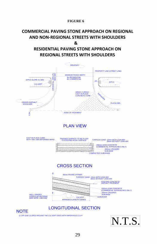
FIGURE 6
COMMERCIAL PAVING STONE APPROACH ON REGIONAL AND NON-REGIONAL STREETS WITH SHOULDERS
& RESIDENTIAL PAVING STONE APPROACH ON
REGIONAL STREETS WITH SHOULDERS
N.T.S.
DRIVEWAY
PROPERTY LINE (STREET LINE)
MINIMUM PAVED WIDTH
3m RESIDENTIAL4m COMMERCIAL
R=4.5m MIN.
PLAN VIEW
DITCH1m
SHO
ULD
ER
CR
OS
SF
ALL M
IN=
2%
MA
X=
8%
DITCH SLOPE 4:1 MIN.
CULVERT
GRAVEL/ASPHALT SHOULDER
EDGE OF PAVEMENT
0.3
m
100mm X 200mmCAST-IN-PLACECONCRETE CURB
CAST-IN-PLACE CURBWITH TWO 15M DEFORMED BARS
FINISHED SURFACE TO BE FLUSHTO EXISTING ROAD SURFACE
150mm LEAN CONCRETE(COMMERCIAL APPROACHES ONLY)
300mm CRUSHEDSUB-BASE
COMPACTED SUBGRADE
CROSS SECTION
PL60mm PAVING STONES
TORPEDO SAND- 15mm WITH LEAN MIX30mm WITHOUT LEAN MIX
EXISTING CONCRETE/ASPHALT PAVEMENT
150mm LEAN CONCRETE(COMMERCIAL APPROACHES ONLY)
300mm CRUSHEDSUB-BASE
SUBGRADECULVERT
PLWELL GRADED
APPROACH LENGTH VARIES
LONGITUDINAL SECTION
TORPEDO SAND- 15mm WITH LEAN MIX30mm WITHOUT LEAN MIX
GRANULAR MATERIAL(SEE NOTE 1 BELOW)
NOTE1) CAP SIDE SLOPES AROUND THE CULVERT ENDS WITH IMPERVIOUS CLAY
.

30
N.T.S.
DRIVEWAY
PROPERTY LINE (STREET LINE)
EXISTING SIDEWALK SHALL BE REMOVED AND
THE APPROACH AND EXPANSION JOINT EXTENDED
BACK TO THE PROPERTY LINE
MINIMUM PAVED WIDTH
3m RESIDENTIAL4m COMMERCIAL
CURB TAPERED TO
EXISTING OR PROPOSED
SIDEWALK RAMP AT < 5% (FIG. 21)
EXISTING OR
PROPOSED
SIDEWALK
BOULEVARD
R=4.5m MIN.
CAST-IN-PLACE
BUTT JOINT
CR
OS
SF
ALL
MIN
=2%
MA
X=
8%
MIN
=2%
MA
X=
4%
CR
OS
SF
ALL
PLAN VIEW
FOR COMMERCIAL APPROACHES ONNON-REGIONAL STREETS WITH CURB >80mm SEE FIG. 23
BARRIER CURB
(SAW CUT AND REMOVE BARRIER CURB AND UNDERLYINGPAVEMENT AND REPLACE WITH 40mm LIP CURB)
CAST-IN-PLACE 100mm X 200mmWITH TWO 15M DEFORMED BARS FINISHED SURFACE TO BE FLUSH
TO EXISTING ROAD SURFACE
SUB-GRADE BASE COURSE
CROSS SECTION
0.3m
PL
1.5m SIDEWALK
PL
APPROACH LENGTH VARIES
TAPER CURB TORAMP CURB
75mm MIN. ASPHALT APPROACH THICKNESS
EXISTING ASPHALT PAVEMENT
BASE COURSERESIDENTIAL=150mm MIN.COMMERCIAL=300mm MIN.
SUBGRADE
LONGITUDINAL SECTION
1) WHEN REPLACING THE CONNECTING SIDEWALK AT AN APPROACH, THE SIDEWALK
MUST MAINTAIN A 5% GRADE OR LESS (EXTRA PANELS MAY NEED TO BE REMOVED)
2) A CROSSFALL OF 2-4% WILL BE REQUIRED THROUGHOUT THE ENTIRE APPROACH
WHERE PROPOSED SIDEWALKS WILL BE CONSTRUCTED AT THE PROPERTY LINE. THIS
APPLIES TO NEWLY INSTALLED OR PROPOSED SIDEWALKS IN NEW DEVELOPMENTS.
NOTE
*SE
E N
OT
E
FIGURE 7
COMMERCIAL ASPHALT APPROACH ON REGIONAL AND NON-REGIONAL STREETS WITH BARRIER CURB
& RESIDENTIAL ASPHALT APPROACH ON
REGIONAL STREETS WITH BARRIER CURB

31
N.T.S.
DRIVEWAY
PROPERTY LINE (STREET LINE)
EXISTING SIDEWALK SHALL BE REMOVED AND
THE APPROACH AND EXPANSION JOINT EXTENDED
BACK TO THE PROPERTY LINE
MINIMUM PAVED WIDTH
3m RESIDENTIAL4m COMMERCIAL
CURB TAPERED TO
EXISTING OR PROPOSED
SIDEWALK RAMP AT < 5% (FIG. 21)
EXISTING OR
PROPOSED
SIDEWALK
BOULEVARD
R=4.5m MIN.
CAST-IN-PLACE
BUTT JOINT
CR
OS
SF
AL
L
MIN
=2
% M
AX
=8%
MIN
=2
% M
AX
=4%
CR
OS
SF
AL
L
PLAN VIEW
FOR COMMERCIAL APPROACHES ONNON-REGIONAL STREETS WITH CURB >80mm SEE FIG. 23
CURB
(SAW CUT AND REMOVE LIP CURB AND UNDERLYINGPAVEMENT AND REPLACE WITH 40mm LIP CURB)
EXISTINGLIP CURB
FINISHED SURFACE TO BE FLUSHTO EXISTING ROAD SURFACE
BASE COURSESUB-GRADE
CROSS SECTION
0.3m
PL
1.5m SIDEWALK
TAPER CURB TORAMP CURB
75mm MIN. ASPHALT APPROACH THICKNESS
EXISTING ASPHALTPAVEMENT
BASE COURSE
RESIDENTIAL=150mm MIN.COMMERCIAL=300mm MIN.
SUBGRADE
LONGITUDINAL SECTION
APPROACH LENGTH VARIES
PL
CAST-IN-PLACE CURB 100mm X 200mmWITH 15M DEFORMED BAR
1) WHEN REPLACING THE CONNECTING SIDEWALK AT AN APPROACH, THE SIDEWALK
MUST MAINTAIN A 5% GRADE OR LESS (EXTRA PANELS MAY NEED TO BE REMOVED)
2) A CROSSFALL OF 2-4% WILL BE REQUIRED THROUGHOUT THE ENTIRE APPROACH
WHERE PROPOSED SIDEWALKS WILL BE CONSTRUCTED AT THE PROPERTY LINE. THIS
APPLIES TO NEWLY INSTALLED OR PROPOSED SIDEWALKS IN NEW DEVELOPMENTS.
NOTE
*SE
E N
OT
E
FIGURE 8
COMMERCIAL ASPHALT APPROACH ON REGIONAL AND NON-REGIONAL STREETS WITH LIP CURB
& RESIDENTIAL ASPHALT APPROACH ON
REGIONAL STREETS WITH LIP CURB
32
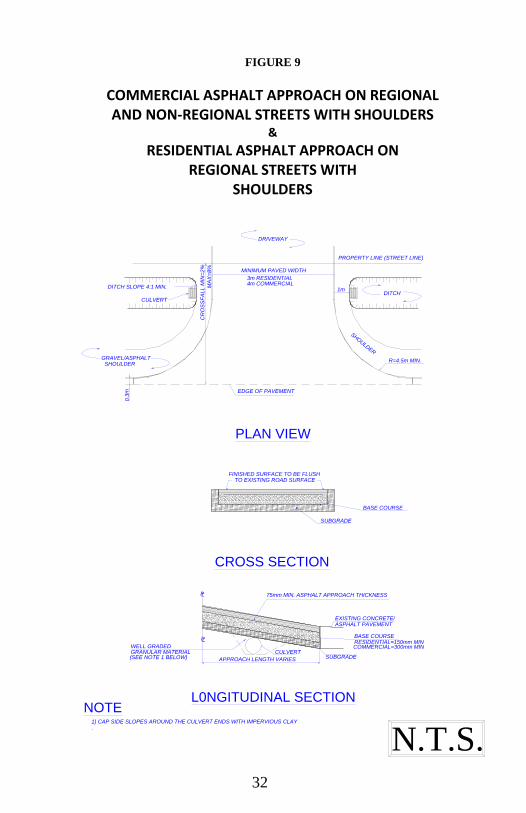
FIGURE 9
COMMERCIAL ASPHALT APPROACH ON REGIONAL AND NON-REGIONAL STREETS WITH SHOULDERS
&
RESIDENTIAL ASPHALT APPROACH ON REGIONAL STREETS WITH
SHOULDERS
DRIVEWAY
PROPERTY LINE (STREET LINE)
MINIMUM PAVED WIDTH
3m RESIDENTIAL4m COMMERCIAL
R=4.5m MIN.
PLAN VIEW
EDGE OF PAVEMENT
0.3
m
DITCH1m
SHOULDER
CR
OS
SF
ALL M
IN=
2%
MA
X=
8%
DITCH SLOPE 4:1 MIN.
CULVERT
GRAVEL/ASPHALT SHOULDER
N.T.S.
FINISHED SURFACE TO BE FLUSHTO EXISTING ROAD SURFACE
BASE COURSE
SUBGRADE
CROSS SECTION
75mm MIN. ASPHALT APPROACH THICKNESS
EXISTING CONCRETE/ASPHALT PAVEMENT
BASE COURSERESIDENTIAL=150mm MINCOMMERCIAL=300mm MIN
PL
PLWELL GRADED
SUBGRADECULVERT
APPROACH LENGTH VARIES
L0NGITUDINAL SECTION
GRANULAR MATERIAL(SEE NOTE 1 BELOW)
NOTE1) CAP SIDE SLOPES AROUND THE CULVERT ENDS WITH IMPERVIOUS CLAY
.

33
FIGURE 10
COMMERCIAL GRAVEL APPROACH ON REGIONAL AND NON-REGIONAL STREETS WITH SHOULDERS
&
RESIDENTIAL GRAVEL APPROACH ON REGIONAL STREETS WITH SHOULDERS
DRIVEWAY
PROPERTY LINE (STREET LINE)
MINIMUM PAVED WIDTH
3m RESIDENTIAL4m COMMERCIAL
R=4.5m MIN.
PLAN VIEW
EDGE OF ROAD SURFACE
0.3
m
DITCH1m
SHO
ULD
ER
CR
OS
SF
ALL M
IN=
2%
MA
X=
8%
DITCH SLOPE 4:1 MIN.
CULVERT
GRAVEL/ASPHALT SHOULDER
N.T.S.
PL
PL
WELL GRADED
CULVERT
APPROACH LENGTH VARIES
LONGITUDINAL SECTION
SUBGRADE
EXISTING GRAVELROAD SURFACE (COMMERCIAL)
EXISTING CONCRETE/ASPHALTGRAVEL ROAD SURFACE(RESIDENTIAL)
GRAVEL APPROACH THICKNESS
RESIDENTIAL=150mm MIN.COMMERCIAL=300mm MIN.
GRANULAR MATERIAL(SEE NOTE 1 BELOW)
NOTE1) CAP SIDE SLOPES AROUND THE CULVERT ENDS WITH IMPERVIOUS CLAY
.

34
CROSS SECTION
FRONTAL PERSPECTIVE OF FINISHEDPRIVATE APPROACH
0.3m 150mm CONCRETE
TAPER CURB TO "0"
FLUSH TO EXISTING CONCRETEREPLACE ASPHALT AS SHOWN
15M TIE BARS600mm LONG AT 600mm O.C.(CONCRETE STREETS ONLY)
75mm BASE COURSE
SUBGRADE
APPROACH LENGTH VARIES
PL
LP
MINIMUM 3m
REF: FIG. 21
FRONT EDGE OFAPPROACH TO BEROLLED OFFGENTLY AS SHOWN
0.5mMINIMUM 5m
2m
0.5m0.5m0.5m
BAR MAT (SEE "REINFORCING STEEL" FIG. 24 & 25)
PROPERTY LINE
(STREET LINE)
EXISTING SIDEWALK SHALL BE REMOVED ANDTHE APPROACH EXTENDED BACK TO THEPROPERTY LINE
EXTENT OF 150mmBARRIER CURB
2m
0.5m0.5m 1m MINIMUM 3m MAXIMUM 6.5m 0.5m0.5m1m
EXTENT OF CURB AND PAVEMENT REMOVAL
PROPOSED OR EXISTING SIDEWALK
MIN
.=2
% M
AX
. 4%
MIN
.=2
% M
AX
. 8%
CR
OS
SF
AL
LC
RO
SS
FA
LL
ROLL OFF THISPORTIONAS SHOWN BELOW
PLAN VIEW
SAW CUT AND REMOVE EXISTINGBARRIER CURB AND PAVEMENT,AND REPLACE WITH 40mm LIPCURB (SEE FIG. 23)
SAW CUT AND REMOVE EXISTING BARRIER CURB AND PAVEMENT
CONSTRUCTION JOINT
FLARE OF APPROACH
15mm EXPANSIONJOINT AS REQUIRED
TAPER CURB TO "0"
DRIVING SURFACE
ROLL CURB TOWARD ROAD
CONTRACTION JOINTAS REQUIRED TOMATCH JOINT IN STREET
NOTE
DRIVEWAY
1) SEE FIG. 22 FOR MANHOLE ISOLATION DETAIL IF REQUIRED.
2) WHEN REPLACING THE CONNECTING SIDEWALK AT AN APPROACH, THE SIDEWALK MUST
MAINTAIN A 5% GRADE OR LESS (EXTRA PANELS MAY NEED TO BE REMOVED).
3) A CROSSFALL OF 2-4% WILL BE REQUIRED THROUGHOUT THE ENTIRE APPROACH WHERE
PROPOSED SIDEWALKS WILL BE CONSTRUCTED AT THE PROPERTY LINE. THIS APPLIES TO NEWLY
INSTALLED OR PROPOSED SIDEWALKS IN NEW DEVELOPMENTS.
IN FIGURE 23
*SE
E N
OT
E
FIGURE 11
RESIDENTIAL CONCRETE APPROACH ON NON-REGIONAL STREETS WITH BARRIER CURB

35
PROPERTY LINE
(STREET LINE)
EXISTING SIDEWALK SHALL BE REMOVED ANDTHE APPROACH EXTENDED BACK TO THEPROPERTY LINE
TAPER CURB TO "0"
ROLL CURB TOWARDDRIVING SURFACE
EXTENT OF 150mmBARRIER CURB
1m
1m MINIMUM 3m MAXIMUM 6.5m 1m
EXTENT OF CURB AND PAVEMENT REMOVAL
PROPOSED OR EXISTING SIDEWALK
ROLL OFF THISPORTIONAS SHOWN BELOW
PLAN VIEW
SAW CUT AND REMOVE EXISTINGBARRIER CURB AND PAVEMENT,AND REPLACE WITH 40mm LIPCURB (SEE FIG. 23)
CONCRETE CURBCAST-IN PLACE REINFORCED PRECAST ORPLASTIC EDGE SUPPORT OR
65mm X 140mm PRECAST CURB OR100mm X 200mm CAST-IN-PLACE CURBWITH TWO 15M DEFORMED BARS
TO EXISTING ROAD SURFACEFINISHED SURFACE TO BE FLUSH
30 mm TORPEDO SAND
60mm PAVING STONES
SUB-GRADE 300mm CRUSHED SUB-BASE
CROSS SECTION
PRIVATE APPROACHFRONTAL PERSPECTIVE OF FINISHED
MINIMUM 3m
REF: FIG. 21
MINIMUM 5m
2m
0.5m0.5m0.5m0.5m
PLASTIC EDGE SUPPORT
DRIVEWAY
1) WHEN REPLACING THE CONNECTING SIDEWALK AT AN APPROACH, THE SIDEWALK
MUST MAINTAIN A 5% GRADE OR LESS (EXTRA PANELS MAY NEED TO BE REMOVED)
2) A CROSSFALL OF 2-4% WILL BE REQUIRED THROUGHOUT THE ENTIRE APPROACH
WHERE PROPOSED SIDEWALKS WILL BE CONSTRUCTED AT THE PROPERTY LINE. THIS
APPLIES TO NEWLY INSTALLED OR PROPOSED SIDEWALKS IN NEW DEVELOPMENTS.
NOTE
0.5m0.5m 0.5m0.5m
MIN
.=2
% M
AX
. 4%
MIN
.=2
% M
AX
. 8%
CR
OS
SF
ALL
CR
OS
SF
ALL
*SE
E N
OT
E
FIGURE 12
RESIDENTIAL PAVING STONE APPROACH ON NON-REGIONAL STREETS WITH BARRIER CURB

36
NOTE
N.T.S.
PROPERTY LINE
(STREET LINE)
EXISTING SIDEWALK SHALL BE REMOVED ANDTHE APPROACH EXTENDED BACK TO THEPROPERTY LINE
PROPOSED OR EXISTING SIDEWALK
PLAN VIEW
CONTRACTION JOINTAS REQUIRED TOMATCH JOINT IN STREET
15mm EXPANSION JOINT AS REQUIRED
CROSS SECTION
0.3m1.5m SIDEWALK
150mm CONCRETE
15M TIE BARS600MM LONG AT600mm O.C.(CONCRETE STREETS ONLY)
LIP CURB
150m
m
ROAD
DEEPEN SECTION TO150mm BELOWEXISTING CONCRETE GUTTER
SUBGRADE
APPROACH LENGTH VARIES
MINIMUM 3m
MINIMUM 6m
PL
75mm BASE COURSE
PL
BAR MAT (SEE "REINFORCING STEEL" FIG. 24 & 25)
FRONTAL PERSPECTIVE OF FINISHEDPRIVATE APPROACH
DRIVEWAY
1) SEE FIG. 22 FOR MANHOLE ISOLATION DETAIL IF REQUIRED.
2) IF CURB HEIGHT >80mm REFER TO FIG. 23.
3) WHEN REPLACING THE CONNECTING SIDEWALK AT AN APPROACH, THE SIDEWALK MUST
MAINTAIN A 5% GRADE OR LESS (EXTRA PANELS MAY NEED TO BE REMOVED).
4) A CROSSFALL OF 2-4% WILL BE REQUIRED THROUGHOUT THE ENTIRE APPROACH WHERE
PROPOSED SIDEWALKS WILL BE CONSTRUCTED AT THE PROPERTY LINE. THIS APPLIES TO
NEWLY INSTALLED OR PROPOSED SIDEWALKS IN NEW DEVELOPMENTS.
1.5m 1.5mMINIMUM 3m MAXIMUM 6.5m
MIN
.=2
% M
AX
. 4%
MIN
.=2
% M
AX
. 8%
CR
OS
SF
ALL
CR
OS
SF
ALL
*SE
E N
OT
E
FIGURE 13
RESIDENTIAL CONCRETE APPROACH ON NON-REGIONAL STREETS WITH LIP CURB

37
N.T.S.
PROPERTY LINE
(STREET LINE)
EXISTING SIDEWALK SHALL BE REMOVED ANDTHE APPROACH EXTENDED BACK TO THEPROPERTY LINE
PROPOSED OR EXISTING SIDEWALK
PLAN VIEW
1.5m 1.5mMINIMUM 3m MAXIMUM 6.5m
REINFORCED PRECAST ORCAST-IN PLACE CONCRETECURB
PLASTIC EDGE SUPPORT OR
EXISTING LIP CURB
CROSS SECTION
WITH TWO 15M DEFORMED BARS100mm X 200mm CAST-IN-PLACE CURB65mm X 140mm PRECAST CURB OR
FINISHED SURFACE TO BE FLUSHTO EXISTING ROAD SURFACE 60mm PAVING STONES
30 mm TORPEDO SAND
SUB-GRADE 300mm CRUSHED SUB-BASE
MINIMUM 3m
MINIMUM 6m
FRONTAL PERSPECTIVE OF FINISHEDPRIVATE APPROACH
NOTE
PLASTIC EDGE SUPPORT OR
DRIVEWAY
1) IF CURB HEIGHT >80mm REFER TO FIG. 23
2) WHEN REPLACING THE CONNECTING SIDEWALK AT AN APPROACH, THE SIDEWALK
MUST MAINTAIN A 5% GRADE OR LESS (EXTRA PANELS MAY NEED TO BE REMOVED)
3) A CROSSFALL OF 2-4% WILL BE REQUIRED THROUGHOUT THE ENTIRE APPROACH
WHERE PROPOSED SIDEWALKS WILL BE CONSTRUCTED AT THE PROPERTY LINE. THIS
APPLIES TO NEWLY INSTALLED OR PROPOSED SIDEWALKS IN NEW DEVELOPMENTS.
MIN
.=2
% M
AX
. 4%
MIN
.=2
% M
AX
. 8%
CR
OS
SF
ALL
CR
OS
SF
ALL
*SE
E N
OT
E
FIGURE 14
RESIDENTIAL PAVING STONE APPROACH ON NON-REGIONAL STREETS WITH EXISTING LIP CURB

38
FIGURE 15
RESIDENTIAL CONCRETE APPROACH ON NON-REGIONAL STREETS WITH SHOULDERS
N.T.S.
PROPERTY LINE
(STREET LINE)
PROPERTY LINETHE APPROACH EXTENDED BACK TO THEEXISTING SIDEWALK SHALL BE REMOVED AND
PLAN VIEW
DITCH SLOPE 4:1 MIN.
CULVERT
GRAVEL/ASHPHALTSHOULDER
SH
OU
LD
ER
LINE OF CULVERT
UNDER APPROACH
MINIMUM 3m MAXIMUM 6.5m1.5m 1.5m
EDGE OF PAVEMENT
PROPOSED OREXISTING SIDEWALK
DITCH
1m
DRIVEWAY
15mm EXPANSION JOINT
SUBGRADE
LONGITUDINAL SECTION
CONCRETE APROACH THICKNESS 150mm MIN.
EXISTING CONCRETE/
ASPHALT PAVEMENT
15M DEFORMED BARS
600mm LONG @600mm O.C.(CONCRETE STREETS ONLY)
75mm BASE COURSE MIN.
CULVERT
WELL GRADED
APPROACH LENGTH VARIES
PL
LP
BAR MAT (SEE "REINFORCING STEEL" FIG. 24 & 25)
NOTE1) SEE FIG. 22 FOR MANHOLE ISOLATION DETAIL IF REQUIRED.
2) WHEN REPLACING THE CONNECTING SIDEWALK AT AN APPROACH, THE SIDEWALK MUST MAINTAIN A
5% GRADE OR LESS (EXTRA PANELS MAY NEED TO BE REMOVED)
3) CAP SIDE SLOPES AROUND THE CULVERT ENDS WITH IMPERVIOUS CLAY
GRANULAR MATERIAL
MIN
.=2
% M
AX
. 4
%M
IN.=
2%
MA
X.
8%
CR
OS
SF
AL
LC
RO
SS
FA
LL
(SEE NOTE 3 BELOW)
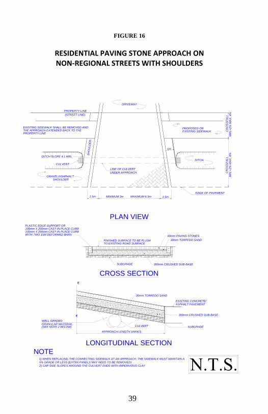
39
FIGURE 16
RESIDENTIAL PAVING STONE APPROACH ON NON-REGIONAL STREETS WITH SHOULDERS
PROPERTY LINE
(STREET LINE)
PROPERTY LINETHE APPROACH EXTENDED BACK TO THEEXISTING SIDEWALK SHALL BE REMOVED AND
PLAN VIEW
DITCH SLOPE 4:1 MIN.
CULVERT
GRAVEL/ASHPHALTSHOULDER
SH
OU
LD
ER
LINE OF CULVERT
UNDER APPROACH
MINIMUM 3m MAXIMUM 6.5m1.5m 1.5m
EDGE OF PAVEMENT
PROPOSED OREXISTING SIDEWALK
DITCH
1m
DRIVEWAY
CROSS SECTION
LONGITUDINAL SECTION
100mm X 200mm CAST-IN-PLACE CURBWITH TWO 15M DEFORMED BARS
FINISHED SURFACE TO BE FLUSHTO EXISTING ROAD SURFACE
SUBGRADE 300mm CRUSHED SUB-BASE
60mm PAVING STONES
30mm TORPEDO SAND
EXISTING CONCRETE/ASPHALT PAVEMENT
300mm CRUSHED SUB-BASE
SUBGRADECULVERT
APPROACH LENGTH VARIES
WELL GRADED
PL
LP
PLASTIC EDGE SUPPORT OR100mm X 200mm CAST-IN-PLACE CURB
NOTE1) WHEN REPLACING THE CONNECTING SIDEWALK AT AN APPROACH, THE SIDEWALK MUST MAINTAIN A
5% GRADE OR LESS (EXTRA PANELS MAY NEED TO BE REMOVED)
2) CAP SIDE SLOPES AROUND THE CULVERT ENDS WITH IMPERVIOUS CLAY
30mm TORPEDO SAND
GRANULAR MATERIAL
MIN
.=2%
MA
X. 4%
MIN
.=2%
MA
X. 8%
CR
OS
SF
ALL
CR
OS
SF
ALL
(SEE NOTE 2 BELOW)
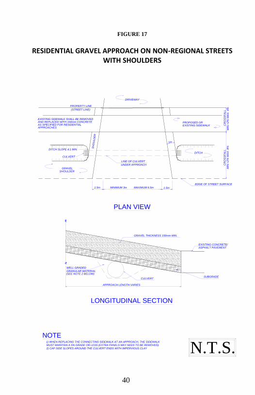
40
FIGURE 17
RESIDENTIAL GRAVEL APPROACH ON NON-REGIONAL STREETS WITH SHOULDERS
EXISTING SIDEWALK SHALL BE REMOVEDAND REPLACED WITH 150mm CONCRETEAS SPECIFIED FOR RESIDENTIALAPPROACHES
PROPERTY LINE
(STREET LINE)
PLAN VIEW
DITCH SLOPE 4:1 MIN.
CULVERT
GRAVELSHOULDER
SH
OU
LD
ER
LINE OF CULVERT
UNDER APPROACH
MINIMUM 3m MAXIMUM 6.5m1.5m 1.5m
EDGE OF STREET SURFACE
PROPOSED OREXISTING SIDEWALK
DITCH
1m
DRIVEWAY
N.T.S.
LONGITUDINAL SECTION
GRAVEL THICKNESS 150mm MIN.
EXISTING CONCRETE/ASPHALT PAVEMENT
SUBGRADECULVERT
APPROACH LENGTH VARIES
WELL GRADED
LP
LP
NOTE1) WHEN REPLACING THE CONNECTING SIDEWALK AT AN APPROACH, THE SIDEWALK
MUST MAINTAIN A 5% GRADE OR LESS (EXTRA PANELS MAY NEED TO BE REMOVED).
2) CAP SIDE SLOPES AROUND THE CULVERT ENDS WITH IMPERVIOUS CLAY
GRANULAR MATERIAL
MIN
.=2%
MA
X. 4%
MIN
.=2%
MA
X. 8%
CR
OS
SF
ALL
CR
OS
SF
ALL
(SEE NOTE 2 BELOW)

41
FIGURE 18
RESIDENTIAL ASPHALT APPROACH ON NON-REGIONAL STREETS WITH SHOULDERS
N.T.S.
PROPERTY LINE
(STREET LINE)
PROPERTY LINETHE APPROACH EXTENDED BACK TO THEEXISTING SIDEWALK SHALL BE REMOVED AND
PLAN VIEW
CROSS SECTION
DITCH SLOPE 4:1 MIN.
CULVERT
GRAVEL/ASHPHALTSHOULDER
SH
OU
LD
ER
LINE OF CULVERT
UNDER APPROACH
MINIMUM 3m MAXIMUM 6.5m1.5m 1.5m
EDGE OF PAVEMENT
PROPOSED OREXISTING SIDEWALK
DITCH
1m
DRIVEWAY
FINISHED SURFACE TO BE FLUSHTO EXISTING ROAD SURFACE
BASE COURSE
SUBGRADE
ASPHALT APPROACH THICKNESS 75mm MIN.
EXISTING ASPHALT
PAVEMENT
WELL GRADED
CULVERT
APPROACH LENGTH VARIES
SUBGRADE
BASE COURSE
RESIDENTIAL=150mm MIN.
LP
LP
LONGITUDINAL SECTION
NOTE1) .WHEN REPLACING THE CONNECTING SIDEWALK AT AN APPROACH, THE SIDEWALK
MUST MAINTAIN A 5% GRADE OR LESS (EXTRA PANELS MAY NEED TO BE REMOVED).
2) CAP SIDE SLOPES AROUND THE CULVERT ENDS WITH IMPERVIOUS CLAY
GRANULAR MATERIAL
MIN
.=2%
MA
X. 4%
MIN
.=2%
MA
X. 8%
CR
OS
SF
ALL
CR
OS
SF
ALL
(SEE NOTE 2 BELOW)

42
PROPERTY LINE
(STREET LINE)
EXISTING SIDEWALK SHALL BE REMOVED ANDTHE APPROACH EXTENDED BACK TO THEPROPERTY LINE
15mm EXPANSION JOINTAS REQUIRED
REINFORCED PRECAST ORCAST-IN-PLACE CONCRETECURB
TAPER CURB TO "0"
ROLL CURB TOWARDDRIVING SURFACE
SAW CUT AND REMOVE EXISTINGBARRIER CURB AND PAVEMENT,AND REPLACE WITH 40mm LIPCURB (SEE FIG. 23)
EXTENT OF 150mmBARRIER CURB
2m
1m MINIMUM 3m MAXIMUM 6.5m 1m
EXTENT OF CURB AND PAVEMENT REMOVAL
65mm X 140mm PRECAST CURB OR100mm X 200mm CAST-IN-PLACE CURBWITH TWO 15M DEFORMED BARS
FINISHED SURFACE TO BE FLUSHTO EXISTING ROAD SURFACE
75mm MIN. THICKNESS ASPHALT
SUB-GRADE 150mm BASE COURSE
PROPOSED OR EXISTING SIDEWALK
ROLL OFF THISPORTIONAS SHOWN BELOW
PLAN VIEW
CROSS SECTION
MINIMUM 3m
2m
MINIMUM 5m0.5m 0.5m 0.5m 0.5m
FRONTAL PERSPECTIVE OF FINISHEDPRIVATE APPROACH
DRIVEWAY
1) WHEN REPLACING THE CONNECTING SIDEWALK AT AN APPROACH, THE SIDEWALK
MUST MAINTAIN A 5% GRADE OR LESS (EXTRA PANELS MAY NEED TO BE REMOVED)
2) A CROSSFALL OF 2-4% WILL BE REQUIRED THROUGHOUT THE ENTIRE APPROACH
WHERE PROPOSED SIDEWALKS WILL BE CONSTRUCTED AT THE PROPERTY LINE. THIS
APPLIES TO NEWLY INSTALLED OR PROPOSED SIDEWALKS IN NEW DEVELOPMENTS.
NOTE
0.5m0.5m 0.5m0.5m
MIN
.=2
% M
AX
. 4
%M
IN.=
2%
MA
X.
8%
CR
OS
SF
AL
LC
RO
SS
FA
LL
*SE
E N
OT
E
FIGURE 19
RESIDENTIAL ASPHALT APPROACH ON NON-REGIONAL STREETS WITH BARRIER CURB

43
FIGURE 20
RESIDENTIAL ASPHALT APPROACH ON NON-REGIONAL STREETS
WITH LIP CURB
N.T.S.
PROPERTY LINE
(STREET LINE)
EXISTING SIDEWALK SHALL BE REMOVED ANDTHE APPROACH EXTENDED BACK TO THEPROPERTY LINE
15mm EXPANSION JOINTAS REQUIRED
REINFORCED PRECAST ORCAST-IN-PLACE CONCRETECURB
PROPOSED OR EXISTING SIDEWALK
1.5m MINIMUM 3m MAXIMUM 6.5m 1.5m
PLAN VIEW
CROSS SECTION
FRONTAL PERSPECTIVE OF FINISHEDPRIVATE APPROACH
NOTE
DRIVEWAY
1) IF CURB HEIGHT >80mm REFER TO FIG. 23
2) WHEN REPLACING THE CONNECTING SIDEWALK AT AN APPROACH, THE SIDEWALK MUST
MAINTAIN A 5% GRADE OR LESS (EXTRA PANELS MAY NEED TO BE REMOVED)
3) A CROSSFALL OF 2-4% WILL BE REQUIRED THROUGHOUT THE ENTIRE APPROACH WHERE
PROPOSED SIDEWALKS WILL BE CONSTRUCTED AT THE PROPERTY LINE. THIS APPLIES TO NEWLY
INSTALLED OR PROPOSED SIDEWALKS IN NEW DEVELOPMENTS.
MINIMUM 3m
MINIMUM 5m
65mm X 140mm PRECAST CURB OR100mm X 200mm CAST-IN-PLACE CURB
WITH TWO 15M DEFORMED BARSFINISHED SURFACE TO BE FLUSHTO EXISTING ROAD SURFACE
75mm MIN. THICKNESS ASPHALT
SUB-GRADE 150mm BASE COURSE
MIN
.=2
% M
AX
. 4%
MIN
.=2
% M
AX
. 8%
CR
OS
SF
ALL
CR
OS
SF
ALL
*SE
E N
OT
E

44
N.T.S.
GRANULAR LEVELLING COURSE
PROPOSED SIDEWALK RAMP
15M DEFORMED BARS 600 mm LONG AT 600 mm O.C.
1st SAWN JOINT
PROPOSED CONCRETE
APPROACH SURFACE
LIMIT OF PAVEMENT
GRADIENT = 2-5%10
± 2
5 R
AS
PROPERTY LINE
(STREET LINE)
50
SIDEWALK RAMP
SIDEWALK RAMP
BARRIER CURB
MODIFIED BARRIER CURB
(SEE FIGURE 27, PAGE 50)
RE
QU
IRE
D
SECTION A-A
NOTE1) SIDEWALK RAMP SURFACE SHALL BE GIVEN A TEXTURED BROOM FINISH ACROSS THE SIDEWALK.
2) 15M TIE BARS SHALL BE PLACED PRIOR TO THE PLACING OF ANY CONCRETE. TIE BARS SHALL
BE BENT AS REQUIRED AND PLACED SO AS TO ENSURE A MINIMUM CONCRETE COVER OF 50mm.
3) WHEN REPLACING THE CONNECTING SIDEWALK AT AN APPROACH, THE SIDEWALK
MUST MAINTAIN A 5% GRADE OR LESS (EXTRA PANELS MAY NEED TO BE REMOVED)
FIGURE 21
CURB RAMP DETAIL FOR COMMERCIAL CONCRETE APPROACHES

45
FIGURE 22
MANHOLE ISOLATION FOR CONCRETE APPROACHES
N.T.S.
DRIVEWAYPROPERTY LINE(STREET LINE)
MANHOLE
ISOLATIONJOINT
ROAD
ISOLATION IF MANHOLE IS MORE THAN 450mm FROM EDGE OF APPROACH
150
mm
'A'
'A'
DRIVEWAYPROPERTY LINE(STREET LINE)
MANHOLE
ROAD
ISOLATION IF MANHOLE IS LESS THAN 450mm FROM EDGE OF APPROACH
ISOLATIONJOINT
150 mm
O.D.
APPROVED BOND BREAKERTO BE BELOW TOP OFCONCRETE AND SEALED.
APPROVED BOND BREAKERTO EXTEND 25 mm TO 50 mmBELOW BOTTOM OF CONCRETE.
M.H. FRAME AND COVER
CONCRETE ISOLATION
GREATER THAN MAXIMUMO.D. OF M.H. TO DEPTH 1mBELOW BOTTOM OFPAVEMENT.
150mm
PLAN VIEW
SECTION A - A
O.D.
'A'
'A'
150mm
300mm
MANHOLE O.D.
MANHOLE ISOLATION DIAMETER
NOTE1) MANHOLE ISOLATION DIAMETER = MANHOLE O.D. + 150mm + 150mm

46
FIGURE 23
CURB AND GUTTER REPLACEMENT FOR RESIDENTIAL APPROACHES; CONCRETE/PAVING STONE OR
ASPHALT ON NON-REGIONAL STREETS WITH BARRIER OR LIP CURB >80mm
N.T.S.
EXISTING CONCRETE
FULL DEPTH SAW CUT
BACK OF EXISTING CURB
REMOVAL
DETAIL 'A'
15M TIE BARS 600mmLONG @ 600 O.C. FOR CONCRETE
JOINT
REPLACEMENT
DETAIL 'A'
PAVEMENT
NOTE: APPLICABLE FOR
EXISTING CURB HEIGHT > 80mm
CURB LINEBACK OF
PAVEMENTEXISTING CONCRETE
FINISHED SURFACE - MATCH EXISTING SURFACE TYPE
300mm
10-15mm
5R
40
mm
300mm
FULL DEPTH SAW CUT
PAVEMENTEXISTING CONCRETE
BACK OF EXISTING CURB
300mm
300mm
150mm 150mm
NEW CONCRETE OR PAVINGSTONE APPROACH
DETAIL 'B'
FINISHED SURFACE - MATCH EXISTING SURFACE TYPE
10-15mm
5R
300mm
150mm 150mm
ASPHALT OVERLAY
DETAIL 'B'
15M TIE BARS 600mmLONG @ 600 O.C. FOR CONCRETE
JOINT
CURB LINEBACK OF
PAVEMENTEXISTING CONCRETE
300mm
NEW CONCRETE OR PAVINGSTONE APPROACH
40mm MIN. OR MATCH EXIST.
CONCRETE PAVEMENT
CONCRETE PAVEMENT
ASPHALT OVERLAY
40mm MIN. OR MATCH EXIST.
EXIST. ASPHALT OVERLAY
40
mm

47
FIGURE 24
RESIDENTIAL APPROACH REINFORCING STEEL SAW CUT LAYOUTS
BAR MAT LAYOUT FOR APPROACHES
2) TRANSVERSE SAW CUT AT PAVEMENT JOINTS. N.T.S.
PROPERTY LINE
EDGE OF PAVEMENT
150 (TYP.)
LAP MIN.470
TYPE 'A' BARMAT
REF. FIG. 25
CUT TO SUIT (TYP.)
15M TIE BARS
600 LONG @ 600 O.C.
A A
A A
75 TYP.
575
15
0 (
TY
P.)
LA
P M
IN.
WPROPERTY LINE
EDGE OF PAVEMENT
10M @ 400 O.C.
75 (TYP.)
15M TIE BARS
600 LONG @ 600 O.C.
150 7
5
75 (TYP.)
ALTERNATIVE 2 - 10M (DEFORMED)
SECTION A-A
ALTERNATIVE 1 - BAR MATS (12.7mm PLAIN)
1) DIMENSIONS ARE IN MILLIMETERS.
NOTE
SAWCUT
EXIST. PAVEMENT JOINT
X
SAWCUT
EXIST.
PAVEMENT
JOINTS
X Y
45°
(TY
P.)
STEEL/PLASTIC CHAIRS INSTALLED PRIOR
TO PLACEMENT OF CONCRETE
Z
Z
3) ALL SAW CUTS SHALL BE 50mm DEEP BY 3 mm WIDE SAW CUTTING LAYOUTS SHOWN ARE TWO POSSIBLE OPTIONS
IF "W" >4300 ADD SAWCUT AT W/2, IF "X" <1000 EXTEND SAWCUT TO POINT "Z", IF "Y" <1000 NO SAWCUT REQUIRED
W

48
FIGURE 25
COMMERCIAL APPROACH SAW CUT LAYOUTS
N.T.S.
NOTE
2) EXISTING SIDEWALK SHALL BE REMOVED AND THE APPROACH AND EXPANSION JOINT
EXTENDED BACK TO THE PROPERTY LINE AS SHOWN.
1) WHERE NO SIDEWALK EXISTS, APPROACH SHALL BE CONSTRUCTED TO PROPERTY LINE.
3) M.H. ISOLATIONS TO BE APPROVED BY CONTRACT ADMINISTRATOR.
4) CONTRACTION JOINTS AS REQUIRED TO MATCH STREET TRANSVERSE JOINTS.

49
FIGURE 26
COMMERCIAL APPROACH REINFORCING STEEL AND
LAYOUT FOR TYPE “A” AND “B” BAR MAT REINFORCEMENT
12.7mm LONGITUDINAL PLAIN BARS,
12.7mm TRANSVERSE PLAIN BARS, LENGTH OF BARS = SLAB WIDTH - 150
2500 LONG.
12.7mm TRANSVERSE PLAIN BARS, LENGTH OF BARS = SLAB WIDTH - 150
2955 LONG.
470470470470470
470470470470470
530 TYP.75 TYP.
75 TYP. 75 TYP.
15
0
TY
P.
150
T
YP
.
LO
NG
ITU
DIN
AL B
AR
S
EQ
UA
LLY
SP
AC
ED
- 5
80 M
AX
.
N.T.S.
BAR MAT 'B' REINFORCEMENT
BAR MAT 'A' REINFORCEMENT
NOTE
2) ALL DIMENSIONS ARE TO CENTRES OF BARS.
3) ALL DIMENSIONS ARE IN MILLIMETERS.
12.7mm LONGITUDINAL PLAIN BARS,
1) ALL BAR MATS JOINTS TO BE ELECTRICALLY SPOT WELDED.
15
0
TY
P.
15
0
TY
P.
LO
NG
ITU
DIN
AL B
AR
S
EQ
UA
LLY
SP
AC
ED
- 5
80 M
AX
.

50
FIGURE 27
APPROACHES LOCATED ADJACENT TO OBSTRUCTIONS, INCLUDING BUT NOT LIMITED TO; FIRE HYDRANTS, HYDRO
POLES AND COMMUNICATION PEDESTALS
DRIVEWAYPROPERTY LINE(STREET LINE)
ROAD
PLAN VIEW
NOTE
2) OBSTRUCTIONS INCLUDE, BUT NOT LIMITED TO;
LAMP STANDARDS, HYDRO POLES AND FIRE HYDRANTS
3) AREA INSPECTORS ARE AVAILABLE TO HELP WITH GEOMETRY OF APPROACH FLARES
1) APPROACHES MUST BE CONSTRUCTED TO MAINTAIN THE MIN. 1.5m CLEARANCE
SIDEWALK
DRIVEWAYPROPERTY LINE(STREET LINE)
ROAD
OBSTRUCTION
SIDEWALK
INCORRECT APPROACH CONSTRUCTION
CORRECT APPROACH CONSTRUCTION
OBSTRUCTION
GEOMETRY OF FLARE CAN
BE DETERMINED WITH THE
HELP OF AN INSPECTOR
1.5m 1.5m
MIN. 3m MAX. 6.5m
1.5m 1.5m
MIN. 3m MAX. 6.5m
1.5 m MIN. DISTANCE
FROM EDGE OF
APPROACH TO
EDGE OF OBSTRUCTION
(SEE NOTE 4 BELOW)
4) CITY FORESTER APPROVAL IS REQUIRED IF A TREE IS WITHIN 2.0m OF THE EDGE OF AN APPROACH
1.5 m MIN. DISTANCE
FROM EDGE OF
APPROACH TO
EDGE OF OBSTRUCTION
(SEE NOTE 4 BELOW)

51
FIGURE 28
MODIFIED BARRIER CURB FOR COMMERCIAL CONCRETE APPROACHES
N.T.S.
INTEGRAL MODIFIED BARRIER CURB
150mm
MIN
.
25R
100R
100R
150mm
200m
m
180m
m
(OR
AS
SP
EC
IFIE
D)

52
GENERAL INFORMATION
APPROVALS/PERMITS for private approaches/walks are coordinated through one of
two divisions of the Public Works Department.
For approvals of:
1) ALL COMMERCIAL / INDUSTRIAL Private Approaches/Walks
&
RESIDENTIAL/FARM PRIVATE Approach/Walks on REGIONAL
STREETS
Contact – Private Approach Technician [email protected]
Traffic Assessment Branch
Transportation Division
Public Works Department
101-1155 Pacific Ave., Winnipeg, MB R3E 3P1
2) RESIDENTIAL / FARM Private Approaches on NON-REGIONAL
STREETS
Contact – Plan Approval/Permit Technologist 204.986.4113
Email: [email protected]
Email only for Plan Approval/Permit Technologist, not for Private
Approach Technician
Technology Services Branch
Engineering Division
Public Works Department
106-1155 Pacific Ave., Winnipeg, MB R3E 3P1
Always contact the applicable technician/technologist when constructing, removing,
relocating or modifying a private approach/walk. The technician/technologist will
determine if an approval/permit is required for the proposed works.
All Permits are issued by the Plan Approval/Permit Technologist at 204.986.4113
An approval/permit is always required to construct a new private approach/walk or for
their reconstruction. When hiring a LICENSED PRIVATE APPROACH
CONTRACTOR you should verify that there is a valid approval/permit.
INSPECTIONS of Private Approaches/Walks are performed by the City of Winnipeg,
Public Works Department, Engineering Division.
TO ARRANGE FOR AN INSPECTION:
A.M RESIDENTIAL INSPECTIONS-Email prior to noon of the previous business day.
P.M. RESIDENTIAL INSPECTIONS-Email prior the end of the previous business day.

53
RESIDENTIAL AND COMMERCIAL APPROACH INSPECTIONS
Provide at least twenty-four (24) hours’ notice to the Residential/Commercial Approach
Inspector. The City of Winnipeg will no longer accept telephone calls for residential/
commercial approach inspections but rather an email to the Residential/Commercial
Approach Inspector will be required (see page 56).
Emails received on Fridays (or the last business day of the week in the event of holidays)
will be accommodated on Mondays (or the first business day of the week in the event of
holidays)
WEATHER CONDITIONS
Concrete shall be adequately protected from freezing for a minimum of five (5) days after
completion of placing operations, or longer as required to ensure that the pavement
opening requirements of Clause 9.9 of Specification CW 3310 are met. A minimum
requirement for protection shall be provided as follows when the air temperature as
forecast by Environment Canada is:
0°C to -3°C The concrete shall be covered with polyethylene film.
-3°C to -5°C Insulated tarp(s) or two sheets of polyethylene film covering, separated by
300 mm of dry straw.
Concrete damaged as a result of inadequate protection against weather conditions shall be
removed and replaced by the Contractor at his own expense.
For temperatures below -5°C a plan of heating and hoarding the concrete shall be
submitted to the Senior Technologist for approval before commencement of work. See
page 56 for Senior Technologist contact information.
APPROACH CULVERTS: DIAMETER, LENGTH & ELEVATION
Culvert diameter to be determined by the City of Winnipeg, Water & Waste
Department, Engineering Division, Land Drainage and Flood Protection Technologist at
204.986.3670.
Contractor to calculate culvert length based on approved approach width, approach
shoulder widths and a minimum 4:1 (rise over run) ditch slope.
For culvert elevations call 204.986.4113 at least five (5) working days prior to the work
commencing.
RE-INSPECTION FEE
Where an inspection takes place and the private approach cannot be approved by the
designated employee because
(a) the work is not at a stage where an inspection of the work can take
place; or
(b) the work has not been carried out in compliance with the By-law;
An inspection fee of $30.00 is payable by the LICENSED CONTRACTOR to the City.

54
MANHOLE & CATCH BASIN ADJUSTMENT
(Reference Spec No. CW 3210 & CW 2130)
The Private Access By-law No. 49/2008, Section 22 requires all manhole adjustments
necessary for the construction of new private approaches in new subdivision be the full
responsibility of the property owner. Any adjustments that are required to the structure
of the manhole i.e. concrete risers; pipe and barrel repairs shall be completed by a
licensed sewer and water contractor. Manholes/catch basins are to be isolated as outlined
on page 45. (See page 56, Contacts & Web Addresses - Licensed Sewer/Water
Contractors) The installation of cast iron lifter rings or installation of levelling bricks
may be performed by an experienced licensed approach contractor. All works must be
performed to the City of Winnipeg Standard Construction Specifications and must be
inspected prior to pouring of the concrete approach, and re-inspected when completed.
If a manhole/catch basin is present, please email the Area Approach Inspector prior to
excavating for the approach. (See Inspector contacts: page 56)
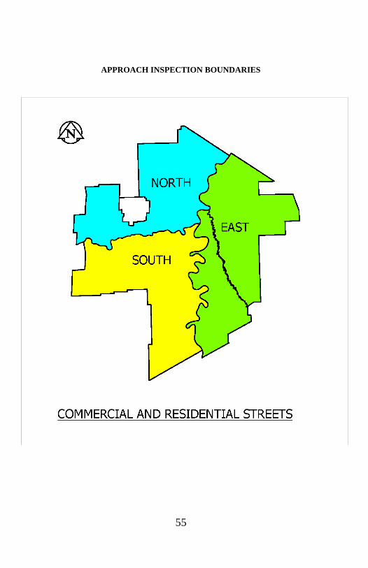
55
APPROACH INSPECTION BOUNDARIES

56
CONTACTS
INSPECTOR CONTACTS
*The Residential Approach Inspectors’ email addresses are only active during the construction
season (approximately May to October, weather dependent)
OTHER CONTACTS & WEB ADDRESSES
Plan Approval/ Permit Technologist (Residential on Non- Regional Streets
Permits/Approvals)…………………………………[email protected] or 204.986.4113
Private Approach Technician (All Commercial & Residential on Regional Streets
Permits and Approvals)………………………………………[email protected]
Customer Services Branch ………………………………………………………...204.986.3184
Streets By-Law No. 1481/77…………….www.winnipeg.ca >Features>By-laws>Streets By-law
Private Access By-Law No. 49/2008........www.winnipeg.ca >Features>By-laws>Private Access
Standard Construction Specifications……………..www.winnipeg.ca/matmgt/Spec/Default.stm
Approved Products…………………………...........www.winnipeg.ca/matmgt/Spec/Default.stm
Snap Edge Canada Ltd.......................................................................................www.snapedge.ca
Licensed Sewer/Water Contractors …………..…………………….
www.winnipeg.ca/waterandwaste/dept/licensedContractors.stm
Licensed Private Access Contractors …... www.winnipeg.ca/publicworks/permitsApprovals/pdf/approaches/list_lic_appr_contractors.pdf
For Culvert Diameter contact City of Winnipeg, Water & Waste Department, Engineering
Division, Land Drainage & Flood Protection Technologist…………………….….204.986.3670
For Development Permit or Variance…………………………………………...204.986.8113
Contact Contact Information
Senior Technologist
(Licensing & Compliance)
204.794.4354
Junior Technologist
(Approach Inquiries, Inspections &
Licensing)
204.794.4060
North Area Residential
Approach Inspector* [email protected]
South Area Residential
Approach Inspector* [email protected]
East Area Residential
Approach Inspector* [email protected]
Commercial
Approach Inspector [email protected]
Granular
Approach Inspector [email protected]

57
NOTES

58
NOTES

59
NOTES

60
NOTES

Published by:
Engineering Division
Public Works Department
The City of Winnipeg
106-1155 Pacific Avenue
Winnipeg, Manitoba R3E 3P1