Embed Size (px)
Citation preview

JET 11
JET Volume 9 (2016) p.p. 11-20Issue 4, December 2016
Type of article 1.01www.fe.um.si/en/jet.html
PRINCIPLES OF WATER HAMMER INTERFEROMETER
OSNOVE VODNO UDARNEGA INTERFEROMETRA
Anton BergantR
Keywords: pipeline, two-valve system, control, water hammer, interference
AbstractThis paper presents a novel water hammer interferometer. In essence, it is an acoustic tube interfer-ometer using the controlled closure of two valves. The device generates two water hammer waves that interfere with each other along the liquid-filled pipeline. The superposition of the two waves can generate pressure head variations of different frequencies and amplitudes. The frequency and shape of pressure histories are controlled via the delayed closure of one of the two valves. The interference phenomena in an ideal pipeline system are described with the aid of basic water hammer theory.
PovzetekPrispevek obravnava nov vodno udarni interferometer. V osnovi je to akustični cevni interfer-ometer, ki je krmiljen z zapiranjem dveh ventilov. Naprava generira dva vodno udarna vala, ki medsebojno delujeta vzdolž s kapljevino napolnjene cevi. Superpozicija teh dveh valov lahko ge-nerira oscilacije tlačnih višin različnih frekvenc in amplitud. Frekvenca in oblika tlačnih valov sta krmiljeni s časovnim zamikom zapiranja enega od dveh ventilov. Interferenčni pojavi v idealnem cevnem sistemu so popisani s pomočjo osnovne teorije vodnega udara.
R Corresponding author: Anton Bergant, PhD, Litostroj Power d.o.o., Litostrojska 50, 1000 Ljubljana, Slovenia, [email protected]

12 JET
Anton Bergant JET Vol. 9 (2016)Issue 4
2 Anton Bergant JET Vol. 9 (2016) Issue 4
----------
1 INTRODUCTION
Liquid-filled pipelines in energy systems undergo a broad range of operating regimes (valve closure, pump failure, turbine shutdown). Unsteady pipe flows may induce large pressure pulsations and pipeline vibrations. Water hammer is the propagation of pressure waves along liquid-filled pipelines (water, oil), and it is induced by a change in flow rate (flow velocity). Most of the water hammer research has been done for a standard case with single-valve closure in a simple reservoir-pipeline-valve system, [1], [2]. However, there are a number of typical industrial pipelines with multiple valves, at least with two of them (upstream- and downstream-end valves). Multiple closing or opening of valves may induce very large or low-pressure waves due to the superposition of the waves, [3], [4].
This paper further investigates the effects of multiple-valve closure (closure of upstream-end and downstream-end valves). The system under consideration is a simple reservoir-valve-pipeline-valve system (two-valve system). The two valves can be closed either simultaneously, or one is shut with a time delay. This may produce large or very low pressures depending on the valve control scenario, [4], [5]. Naturally, the different position of two valves may also play a major role, [6], but this is not the subject of this paper. The two valves are positioned at the two far ends. In essence, the system with two closing far-end valves generates two water hammer waves that superimpose at some point along the pipeline. This causes interference from the physical effects of superimposing two waves, [7]. The superposition of waves can generate a wave of greater, lower or the same amplitude. More strictly, interference refers to the interaction of waves that are correlated or coherent with each other, [8]. In nature, interference effects can be observed with all types of waves, including acoustic waves (for example our case study with pressure waves in closed conduit), surface water waves, light waves, etc. In 1833, Herschel first developed an idea of acoustic interference, [9]. Then in 1866 Quincke, [10], experimentally proved Herschel's cancellation of acoustic waves. This lead to the development of the Herschel-Quincke tube that is, in essence, a bypass pipe connected to the main pipeline. Pressure pulsations in the pipeline are controlled by the right relation between the length of the main pipe between T-junctions and the length of the by-pass line.
The concept of a proposed acoustic tube interferometer using the controlled action of two valves is new. Because the two waves are water hammer waves, the device is called water hammer interferometer. This paper first presents the basic water hammer theory that is used for the detailed description of the interferometer in the core of the paper.
2 BASIC WATER HAMMER THEORY
The water hammer phenomenon is traditionally explained by considering an ideal reservoir-pipe-valve system (frictionless) in which a steady flow with velocity V0 is stopped by an instantaneous valve closure (see Fig. 1). The valve closure generates a pressure wave that travels at the wave speed, a, towards the reservoir at a distance, L. The pressure rise, p, induced by the pressure wave is given by the Joukowsky formula, [1], [2]:
0aVp (2.1)
where ρ is the mass density of the fluid. Herein it is assumed that pressure never drops below the liquid vapour pressure during a water hammer event.

JET 13
Principles of water hammer interferometer Principles of water hammer interferometer 3
----------
Figure 1: Reservoir-pipe-valve system In the hydropower and pump industries, the pressure p is replaced by the piezometric head (pressure head) H (H = p/(ρg)) and flow velocity V0 with velocity amplitude V = 0 V0 = V0; then Eq. (2.1) may be written as
VgaH (2.2)
Pressure waves in the ideal system are plane waves, and the resulting pressure head traces are obtained from Eq. (2.2). For a valve closure event in a simple reservoir-pipe-valve system, there are two basic dimensionless numbers, [1]: (1) dimensionless pressure (pressure head change divided by Joukowsky head rise: (H-H0)/((a/g)V0) in our case) and (2) dimensionless time (time divided by wave reflection time: t/(L/a)). Pressure head waves in the ideal system of Fig. 1 at the downstream end (x/L = 1), at the midpoint (x/L = 1/2) and at the upstream end of the pipe system (x/L = 0) are presented in a dimensionless form in Fig. 2.
Figure 2: Dimensionless pressure head histories in the ideal reservoir-pipe-valve system: Instantaneous closure of the downstream end valve VD
The complete period resulting from an instantaneous valve closure in this open-closed system is 4L/a (Fig. 2). The corresponding natural frequency of the vibration is a/(4L). The phenomenon can be described as follows:
1) 0 < t L/a: After instantaneous valve closure, the high-pressure head wave H (HH0
(a/g)V0) travels towards the upstream end reservoir at a wave speed a. At time L/a, all the liquid is brought to rest, and the wave reflects off the constant head reservoir.

14 JET
Anton Bergant JET Vol. 9 (2016)Issue 4
4 Anton Bergant JET Vol. 9 (2016) Issue 4
----------
2) L/a < t 2L/a: The reflected negative wave H travels back to the downstream end valve. At time 2L/a all the liquid has a velocity V0 (reverse velocity) and the wave reflects off the closed valve as a negative wave H.
3) 2L/a < t 3L/a: The low-pressure head wave H travels towards the reservoir. At time 3L/a all the liquid in the pipe is brought to rest, and the wave reflects off the reservoir as positive wave H.
4) 3L/a < t 4L/a: The H-wave travels back to the closed downstream end valve (dead end). At time 4L/a, all the liquid in the pipe has a velocity V0. At this instant, the conditions are the same as at the instant of the instantaneous closure.
The time interval of 4L/a is termed the theoretical period of the pipeline, [2]. The pressure head variations repeat forever; however, in reality, the pressure head variations will die out because of skin friction and other damping mechanisms [11], [12].
3 WATER HAMMER INTERFEROMETER PRINCIPLES
The proposed water hammer interferometer is comprised of an upstream end constant-head reservoir, a valve positioned adjacent to the reservoir (valve VU), pipeline, and a downstream end valve (valve VD) (see Fig. 3). Water hammer waves are induced by the closure of the two valves (valves VU and VD) either simultaneously, or one of them shuts with delay (either VU or VD). The reservoir is the source of energy. Let us consider an ideal frictionless system and instantaneous valve closure for the easiest visualization of the two pressure head (water hammer) waves. Then water hammer phenomena can be explained by the simple relations presented in Section 2. Transient phenomena are investigated by comparing the responses of an ideal standard reservoir-pipe-valve system (Section 2) and an ideal water hammer interferometer (reservoir-valve-pipe-valve system). Pressure head traces are depicted in a dimensionless form at the downstream end (x/L = 1), at the midpoint (x/L = 1/2) and at the upstream end of the pipe system. Dimensionless head traces are the same for any similar pipeline system. Results are presented for the case of simultaneous valve closure and for the case of delayed closure of the upstream end valve VU (time delay: 0 < td,VU 4L/a). Flow situations with the delayed closure of the downstream end valve VD are more complex. In the ideal system, the wave phenomena are similar to the case with the delayed closure of the valve VU when (1) the valve VD shuts with a delay less than L/a or (2) a second constant-head reservoir is simply attached to the downstream end. Wave phenomena in systems with two acting valves positioned at an arbitrary location along the pipeline are even more complex and require detailed transient analysis, [1], [2].
Principles of water hammer interferometer 5
----------
Figure 3: Reservoir-valve-pipe-valve system
Figure 4 presents pressure head response for the case of simultaneous valve closure and for the case of delayed closure of the upstream end valve VU with a time delay from 0 to 2L/a. The time period of 2L/a is actually the round-trip wave travel time. Figure 4a repeats pressure head response in the conventional reservoir-pipe-valve system that is well explained in Section 2. The theoretical period of head variations is 4L/a, and it is equal to the theoretical period of the pipeline (Section 2).
The flow situation for the two-valve closure case is more complex. Simultaneous valve closure (Fig. 4b) produces pressure head variations at the two far end valves with a period of 2L/a, whereas the head at the midpoint remains constant at all times. In this case, interference of the two water hammer waves produces waves of different frequencies and cancellation of waves in comparison to the case of single-valve closure (Fig. 4a). The delayed closure of the upstream end valve VU at the time of 0.5L/a and at 1.5L/a after VD closure shows a similar response (Figs. 4c and 4e). In this case, pressure heads at the two far end valves vary with a period of 2L/a, whereas the pressure head at the midpoint exhibits variation in the period of L/a. Pressure head in the midpoint never drops below the initial static head. Even more striking is the response of the second valve closure (VU) at time L/a after the first valve closure (VD; Fig. 4d). The interference of two water hammer waves completely cancels the pressure variations at the two valves and at the midpoint. Moreover, the pressure head is increased by the Joukowsky pressure head rise of (a/g)V0. The interferometer works as a pressure head amplifier. The flow situation induced by the second valve closure (VU) at time 2L/a after the first valve closure (VD; Fig. 4f) is in a way similar to the situation of simultaneous valve closure (Fig. 4b). Wave interference produces pressure head variations at the two far end valves with a period of 2L/a, whereas the head at the midpoint remains constant at all times.

JET 15
Principles of water hammer interferometer
Principles of water hammer interferometer 5
----------
Figure 3: Reservoir-valve-pipe-valve system
Figure 4 presents pressure head response for the case of simultaneous valve closure and for the case of delayed closure of the upstream end valve VU with a time delay from 0 to 2L/a. The time period of 2L/a is actually the round-trip wave travel time. Figure 4a repeats pressure head response in the conventional reservoir-pipe-valve system that is well explained in Section 2. The theoretical period of head variations is 4L/a, and it is equal to the theoretical period of the pipeline (Section 2).
The flow situation for the two-valve closure case is more complex. Simultaneous valve closure (Fig. 4b) produces pressure head variations at the two far end valves with a period of 2L/a, whereas the head at the midpoint remains constant at all times. In this case, interference of the two water hammer waves produces waves of different frequencies and cancellation of waves in comparison to the case of single-valve closure (Fig. 4a). The delayed closure of the upstream end valve VU at the time of 0.5L/a and at 1.5L/a after VD closure shows a similar response (Figs. 4c and 4e). In this case, pressure heads at the two far end valves vary with a period of 2L/a, whereas the pressure head at the midpoint exhibits variation in the period of L/a. Pressure head in the midpoint never drops below the initial static head. Even more striking is the response of the second valve closure (VU) at time L/a after the first valve closure (VD; Fig. 4d). The interference of two water hammer waves completely cancels the pressure variations at the two valves and at the midpoint. Moreover, the pressure head is increased by the Joukowsky pressure head rise of (a/g)V0. The interferometer works as a pressure head amplifier. The flow situation induced by the second valve closure (VU) at time 2L/a after the first valve closure (VD; Fig. 4f) is in a way similar to the situation of simultaneous valve closure (Fig. 4b). Wave interference produces pressure head variations at the two far end valves with a period of 2L/a, whereas the head at the midpoint remains constant at all times.

16 JET
Anton Bergant JET Vol. 9 (2016)Issue 4
6 Anton Bergant JET Vol. 9 (2016) Issue 4
----------
Figure 4: Dimensionless pressure head histories in the ideal reservoir-valve-pipe-valve system: Instantaneous closure of the end valves, first VD and then VU (time delay: 0td,VU2L/a)
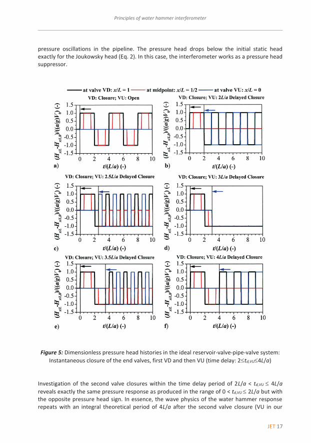
Figure 5 presents the pressure head response for the case of delayed closure of the upstream end valve VU with a time delay from 2L/a to 4L/a. This period is actually the second round trip wave period in the conventional reservoir-pipe-valve system (Fig. 5a). As stated before, the flow situation induced by the second valve closure (VU) at time 2L/a after the first valve closure (VD; Figs. 4f and 5b) is similar to the situation of simultaneous valve closure (Fig. 4b). The delayed closure of the valve VU at the time of 2.5L/a and at 3.5L/a after VD closure shows a similar response (Figs. 5c and 5e). Pressure heads at valves VD and VU vary with a period of 2L/a, respectively. Pressure head at the midpoint oscillates with a period of L/a, and it never exceeds the initial static head. The second valve closure (VU) at time 3L/a after the first valve closure (VD) is shown in Fig. 5d. The interference of two water hammer waves completely attenuates
JET 17
Principles of water hammer interferometer Principles of water hammer interferometer 7
----------
pressure oscillations in the pipeline. The pressure head drops below the initial static head exactly for the Joukowsky head (Eq. 2). In this case, the interferometer works as a pressure head suppressor.
Figure 5: Dimensionless pressure head histories in the ideal reservoir-valve-pipe-valve system: Instantaneous closure of the end valves, first VD and then VU (time delay: 2td,VU4L/a)
Investigation of the second valve closures within the time delay period of 2L/a < td,VU 4L/a reveals exactly the same pressure response as produced in the range of 0 < td,VU 2L/a but with the opposite pressure head sign. In essence, the wave physics of the water hammer response repeats with an integral theoretical period of 4L/a after the second valve closure (VU in our

18 JET
Anton Bergant JET Vol. 9 (2016)Issue 4
8 Anton Bergant JET Vol. 9 (2016) Issue 4
----------
case). Within the frame of the integral theoretical period, there are a number of responses with periods of 2L/a and L/a and situations with constant pressure along the complete length of the pipeline. When one compares the conventional single-valve closure case with the two-valve closure one (Figs. 4 and 5), it is evident that the delayed closure of the second valve (VU in our case study) has a profound effect on the pressure head traces in the pipeline system.
4 CONCLUSIONS
This paper investigates the effects of multiple-valve closure (closure of upstream-end and downstream-end valves) on pressure head response. The system under consideration is a simple reservoir-valve-pipeline-valve system (two-valve system). The two valves can be closed either simultaneously, or one is shut with a time delay. This may produce large or low pressures heads depending on the valve control scenario. The system with two rapid closing far end valves generates two water hammer waves that superimpose (interfere) at some point along the pipeline. Superposition of waves can generate pressure heads of greater, lower or the same amplitude. Interference refers to the interaction of waves that are correlated or coherent with each other. The concept of an acoustic tube interferometer using controlled action of two valves is proposed. Because the two waves are water hammer waves, the device is called water hammer interferometer. The paper presents basic water hammer theory that is used for the detailed description of the interferometer. When one compares pressure response produced by the conventional single-valve closure with the one produced by the water hammer interferometer (two-valve closure), one finds that the time delay of closure of the second valve has a profound effect on the pressure head traces in the pipeline system.
References
[1] E.B. Wylie, V.L. Streeter: Fluid Transients in Systems, Prentice Hall, 1993 [2] M.H. Chaudhry: Applied Hydraulic Transients, Springer, 2014
[3] A. Bergant, J.M.C. van’t Westende, T. Koppel, J. Gale, Q. Hou, Z. Pandula, A.S. Tijsseling: Water hammer and column separation due to accidental simultaneous closure of control valves in a large scale two-phase flow experimental test rig, Pressure Vessels and Piping Division Conference, ASME, Bellevue, Washington, USA, 2010
[4] A. Bergant, U. Karadžić: Developments in valve-induced water-hammer experimentation in a small-scale pipeline apparatus, 12th International Conference on Pressure Surges, BHR Group, Dublin, Ireland, 2015
[5] Y. Liu, Z. Huang, C. Jiang: Characteristics of water hammer induced valve-valve system, 2015 International Conference on Fluid Power and Mechatronics, IEEE, Harbin, China, 2015
[6] S. Ikeo, T. Kobori: Water hammer caused by valve stroking in a pipe with two valves, Buletin of JSME, JSME, Vol. 18, Iss. 124, p.p. 1151 – 1157, 1975
[7] G.S. Chaddha: University Physics for Engineering and Science Students, Alpha Science International Ltd, 2015

JET 19
Principles of water hammer interferometer Principles of water hammer interferometer 9
----------
[8] Interference (wave propagation), Wikipedia [world wide web], available at: http://en.wikipedia.org/wiki/Interference_(wave_propagation)/(19.12.2016)
[9] Sir J.F.W. Herschel: On the absorbtion of light by coloured media, viewed in connection with undulatory theory, The Philosophical Magazine, Vol. 3, Iss. 18, p.p. 401 – 412, 1833
[10] G. Quincke: Ueber Interferenzapparate für Schallwellen, Annalen der Physik und Chemie, Vol. 128, Iss. 6, p.p. 177 – 192, 1866
[11] A. Bergant, A.S. Tijsseling, J.P. Vítkovský, D.I.C. Covas, A.R. Simpson, M.F. Lambert: Parameters affecting water-hammer wave attenuation, shape and timing. Part 1: Mathematical tools, Journal of Hydraulic Research, IAHR, Vol. 46, Iss. 3, p.p. 373 – 381, 2008
[12] A. Bergant, A.S. Tijsseling, J.P. Vítkovský, D.I.C. Covas, A.R. Simpson, M.F. Lambert: Parameters affecting water-hammer wave attenuation, shape and timing. Part 2: Case studies, Journal of Hydraulic Research, IAHR, Vol. 46, Iss. 3, p.p. 382 – 391, 2008
Nomenclature
(Symbols) (Symbol meaning)
a g H L p V t td x H p V
water hammer wave speed gravitational acceleration piezometric (pressure) head length pressure flow velocity time time delay distance pressure head change pressure change flow velocity change mass density
(Subscripts) mp VD VU 0
(Superscripts)
(Subscripts meaning) midpoint downstream end valve upstream end valve initial conditions (Superscripts meaning)
20 JET
Anton Bergant JET Vol. 9 (2016)Issue 4
10 Anton Bergant JET Vol. 9 (2016) Issue 4
----------
(Abbreviations)
VD VU
(Abbreviations meaning) downstream end valve upstream end valve
Acknowledgments
The author wishes to thank Slovenian Research Agency (ARRS) for the support of this research conducted through the project L2-5491 (ARRS).