Embed Size (px)
Citation preview

CHAPTER 3
PRINCIPLES OF MISSILE FLIGHT
AND JET PROPULSION
INTRODUCTION
In this chapter and the next we will take up the subject of guided missiles in general. As a GMM, the information in these two chapters will help you to understand the missiles used in the launching systems. Also, the information here represents a substantial portion of the knowledge required by your advancement qualifications. Specifically, this chapter deals with basic flight principles, the principle of jet propulsion, and the various types of missile propulsion systems. Chapter 4 covers missile components such as SERVOMECHANISMS and GYROS, and the various types of missile guidance systems. You are urged to study these two chapters carefully since the remainder of this course will concentrate primarily on launching systems. Whatever knowledge you can gain in chapters 3 and 4 will be of considerable help to you in understanding the material which follows.
MISSILE AERODYNAMICS Guided missiles launched from surface ships have their flight paths within the earth's atmosphere, so it is important that you understand some basic aerodynamic principles. Aerodynamics may be defined as the science that deals with the motion of air and other gases, and with the forces acting on bodies moving through these gases. THE ATMOSPHERE The atmosphere is a gaseous envelope surrounding the earth to a height of roughly 250 miles. Although there is some difference of opinion as to where the atmosphere ends and space begins, the limit defined above is quite generally accepted. So far as tangible evidence goes, the 750-mile upper limit of the aurora borealis is the "top" of the atmosphere. The behavior of the electrical discharges indicates that elements of air are present, although extremely rare.
As mentioned in chapter 2, one of the most important characteristics of the atmosphere is that air density changes with altitude. As altitude increases, air density decreases significantly. At sea level, the density of air is about .076 pound per cubic foot. At 20,000 feet, air density is only about .0405 pound per cubic foot. Because of the decrease in air density with altitude, a missile flying at 35,000 feet encounters less air resistance-that is, has less drag-than a missile flying close to sea level. Air pressure also varies with altitude. The pressure acting on each square inch of the earth's surface at sea level is actually the weight of a column of air one inch square, extending from sea level to the outer limits of the atmosphere. On a mountain top, this column of air would be shorter, and so the weight (pressure) acting on ' each square inch would be less. Therefore, air pressure decreases as altitude increases. Another characteristic of the atmosphere which changes with altitude is temperature (see fig. 3-1). But, unlike density and pressure, temperature does not vary directly with altitude. From sea level to about 35,000 feet, the temperature drops steadily at a rate of approximately 3 1/2°F per thousand feet. It then remains fairly constant at -67°F up to about 105,000 feet. It then increases at a steady rate until another constant- temperature zone is reached. This zone lasts for several miles. Then the temperature starts decreasing. The procedure repeats itself - that is, a second temperature minimum is reached, and after a short constant-temperature zone, it starts rising again. These temperature minimums mark the boundaries between the four regions in the atmosphere: the troposphere, the stratosphere, the mesosphere, and the thermosphere, shown in figure 3-2. In this figure the regions beyond are simply labeled "outer space," but they may be divided into further layers, according to the findings of space probes and explorations of recent times.
32

CHAPTER 3 - PRINCIPLES OF MISSILE FLIGHT AND JET PROPULSION
Troposphere The troposphere is the lowest layer of the atmosphere and extends from the surface of the earth to a height of 10 miles. This is not a firm figure, as the height of the troposphere varies over different parts of the earth. Near the poles it may be only 4 miles. It is made up mostly of nitrogen and oxygen, and accounts for three- fourths of the weight of the atmosphere. Within this layer temperature decreases with altitude, and it is here that clouds, snow, rain, and the seasonal changes occur.
Because the troposphere is dense, aerodynamic surfaces can be used efficiently to control missiles. However, this high density causes a large amount of drag. You will remember from chapter 2 that the dense lower atmosphere slows down a projectile. It will have the same effect on a missile. The German V-2, rocket which was used to bomb England during World War II, was slowed down from 3300 to 1800 mph as it passed through the troposphere. The friction of the air also causes extremely high skin temperatures on missiles or reentry craft, high enough to melt common metals.
33

GUNNER'S MATE M 3 & 2
Stratosphere The stratosphere is the layer of air above the troposphere. Its upper limits are around 20 miles above sea level. In this region temperature no longer decreases with altitude, but stays nearly constant and actually begins to increase in the upper levels. Higher temperatures in the upper levels are caused by ozone which is heated by ultraviolet radiation from the sun. (Ozone is a gas which is produced when electricity is discharged through oxygen.) The composition of the stratosphere is similar to that of the troposphere; however, there is practically no moisture in the stratosphere. There are almost no clouds and no storms, and an almost complete absence of dust. At the earth's surface the air contains about 21 percent oxygen, but this decreases to a small value in the stratosphere, while the percent of hydrogen rises from 0.01 percent to 95 percent. The air is said to be "thin" and will not support human life nor air breathing engines. Propeller-driven vehicles cannot penetrate this region because of the low air density, and aerodynamic surfaces have greatly reduced effect in controlling missiles. But increases in missile speeds are possible because thrust is used more for acceleration and less to overcome drag. Mesosphere Above the stratosphere is the mesosphere, extending from about 19 miles to 50 miles.
Within this region the minim\lm temperature is reached at about 47 1/2 nautical miles (fig. 3-1), decreasing from about 7°C at its lower edge to -100°C at its upper limit. Ozone is generated in this region and it is the seat of transformation of most primary into secondary radiation. Intense meteor trains reach down into the mesosphere and their brilliant combustion gave rise to the belief that this was a region of comparatively high temperature. Intermediate Layers In figure 3-1 you find the words "tropopause," "stratopause," and "mesopause." These are applied to rather narrow regions between the layers described above. In each case, they are the regions of transition from one type of atmosphere to the next one, and are likely to have turbulence because of the inversion or reversal characteristics. Thermosphere The thermosphere starts at about 47 1/2 nautical miles (fig. 3-1) and extends to the ionosphere. Sometimes the two areas are considered as the ionosphere as they have a continuing upward trend in temperature. The increase in temperature IS due to the presence of ozone, which is formed by the action of ultraviolet rays from the sun on the oxygen in the atmosphere. Tremendous fluctuations of wind speed (70 knots or more) occur on a daily basis. These fluctuations are referred to as atmospheric tides. Ionosphere Above the thermosphere, ranging up to about 250 miles above sea level, is the ionosphere. This is a region rich in ozone, and consists of a series of electrified layers. The ionosphere is extremely important because it refracts (bends) radio waves (fig. 3-2). This property enables a radio transmitter to send waves to the opposite side of the world by a series of refractions and reflections taking place in the ionosphere and at the surface of the earth. The characteristics of the ionosphere vary with daylight and darkness, and also with the four seasons. The term "ionosphere" is used particularly in referring to the electrical characteristics of the region, while "exosphere" is the name used when referring to the meteorological aspects.
34

CHAPTER 3 - PRINCIPLES OF MISSILE FLIGHT AND JET PROPULSION
Higher Atmospheres The reaches of space beyond the ionosphere have not been fully explored and much of the information about them is conjecture. Much information about the upper air has been transmitted to earth from orbiting satellites and spacecraft which have carried instruments to measure radiation, temperature, and other information that could be measured. Weather information, and reports of meteorites and micrometeorites are recorded. There is still a great deal more to learn about space. If you read different writers on the subject, you will find variations in statements about the size of atmospheric zones and even differences in names for the regions. As conjecture is replaced by real information, these differences will be resolved. Several belts of high intensity charged particles, called Van Allen Belts, surround the earth in space. They were discovered by the early U. S. satellites, Explorer I and Explorer II, in 1958. The zones fluctuate and it is believed solar flares or other phenomena of the sun cause the changes. It is almost certain that the outer zone owes its existence to ionized solar gas ejected from the sun.
BASIC FLIGHT PRINCIPLES The principles of low speed aerodynamics which underlie the operation of most aircraft also apply to missiles, at least in the first few seconds of flight. Before we discuss high speed missile flight, let us consider the motions and forces that are common to both guided missiles and conventional airplanes flying at low speeds. BASIC MOTIONS Like any moving body, the guided missile executes two basic kinds of motions: rotation and translation. In pure rotation all parts of a body pivot about the center of gravity, describing concentric circles around it. In movements of translation, or linear motions, the center of gravity of a body moves along a line, and all the separate parts follow lines parallel to the path of the center of gravity. Any possible motion of the body is composed of one or the other of these motions, or is a combination of the two. Since missiles are free to move in three dimensions, we describe their motions by using a reference system containing three reference
lines, or axes. The missile axes (fig. 3-3A) are mutually perpendicular lines which intersect at the center of gravity of the missile. A missile can make three kinds of rotary movements: pitch, roll, and yaw. Pitch, or turning up or down is rotation about the lateral or Y axis of the missile (fig. 3-3B). The missile rolls, or twists, about the longitudinal axis, which is the reference line running through the nose and tail and designated the X axis in figure 3-3C. It yaws, or turns to the right or left, about the Z or vertical axis (fig. 3-3D). Rotary motions about all three of these axes are controlled by devices within the missile. Hereafter, these axes will be referred to as the pitch axis, the roll axis, and the yaw axis. The second type of movement is called translation. Translation includes any linear movement of the missile. For example, a sudden gust of wind or an air pocket could throw a missile a considerable distance off its trajectory without causing any significant angular movement. If you have ever flown in an airplane, this should be fairly easy to understand. If the plane hits an air pocket, it may drop sever al hundred feet, but still maintain a straight and level altitude. Any linear movement, regardless of direction, can be resolved into three components: lateral movement, vertical movement and movement in the direction of thrust. So, besides the three angular degrees of movement, we have three linear degrees of movement. A missile in flight can therefore be said to have six degrees of movement, or freedom. In an airplane. the pilot checks his instruments or visually observes angular and linear movement. On the basis of his observations, he repositions the control surfaces as necessary to keep the plane where he wants it. Since we don't have a pilot in a guided missile to note these movements, we install devices that will detect them, as will be discussed in chapter 4. AERODYNAMIC FORCES The principal forces acting on a missile in level flight are thrust, drag, weight, and lift. Like any forces, each of these is a vector quantity. You will remember from your study of Mathematics, Navpers 10069-C, that a vector has magnitude (length) and direction. These forces are illustrated in figure 3-4. Thrust (force) is directed along the longitudinal axis of the missile and is the force
35

GUNNER'S MATE M 3 & 2
36

CHAPTER 3 - PRINCIPLES OF MISSILE FLIGHT AND JET PROPULSION
which propels it forward at speeds sufficient to sustain flight. Drag is the resistance air offers to the passage of the missile through air, and is directed rearward. The weight of the missile is the pull of gravity on the missile, and is directed downward toward the center of the earth. Opposed to the force of gravity is lift, an upward force which supports the missile. Lift is directed perpendicular to the direction of drag. Lift is produced by means of pressure differences. The primary factor contributing to lift is that the air pressure on the upper surface of an airfoil (wing) must be less than the pressure on the underside. The amount of lifting force provided is dependent to a large extent on the shape of the wing. Additional factors which determine the amount of lift are the wing area, the angle at which the wing surface is inclined to the airstream (angle of attack), and the density and speed of the air passing around it. The airfoil that gives the greatest lift with the least drag in subsonic (less than the speed of sound) flight has a shape similar to the one illustrated in figure 3-5.
Some of the standard terms applied to airfoils are included in the sketch. The foremost edge of the wing is called the leading edge, and that at the rear the trailing edge (fig. 3-5A). A straight line between the leading and the trailing edges is called the chord. The distance from one wingtip to the other (not shown) is known as the SPAN. The angle of incidence (fig. 3-5B) is the angle between the wing chord and the longitudinal axis of the fuselage. In figure 3-5C, the large arrow indicates the relative wind, the direction of the airflow with reference to the moving airfoil. The angle of attack is the angle between the chord and the direction of the relative wind. In actual flight, a change in the angle of attack will change the airspeed. But if for test purposes we maintain a constant velocity of the airstream while changing the angle of attack, the results on the nonsymmetrical wing will be as shown in figure 3-6. The sketches show a wing section at various angles of attack, and the effect these different angles have on the resultant force and the position of the center of pressure. The burble point referred to in
37

GUNNER'S MATE M 3 & 2
figure 3-6C and D is the point at which airflow over the upper surface becomes rough, causing an uneven distribution of pressure. Note that the center of pressure changes with the angle of attack. The relative wind strikes the tilted surface, and as the air flows around the wing, different amounts of lifting force are exerted on various points on the airfoil. The sum (resultant) of all these forces is equivalent to a single force acting at a single point and in a particular direction. This point. is called the center of pressure. From it, lift can be considered to be directed perpendicular to the direction of the relative wind. The dynamic or impact force of the wind against the lower surface of the airfoil also contributes to lift, but no more than one-third of the total lift effect is provided by this impact force. ACCELERATION Acceleration is rate of change, either in speed or in direction of motion or both. A missile accelerates in a positive or negative sense as it increases or decreases speed along its line of flight. It also accelerates in a positive or negative sense as it changes direction in turns, dives, pullouts, and as a result of gusts of wind. During accelerations a missile is subjected to large forces which tend to keep it flying along its original line of flight. This is in accordance with Newton's first law of motion which states:
A particle remains at rest or in a state of uniform motion in a straight line unless acted upon by an external force. Like gravity, acceleration is measured in terms of g's. The acceleration of a body in free fall is said to be one "g." Missiles making rapid turns or responding to large changes in thrust will experience accelerations many times that of gravity, the ratio being expressed as a number of "g's." The number of "g's" which a missile can withstand is one of the factors which determines its maximum turning rate and the type of launcher suitable for the weapon. The delicate instruments contained in a missile may be damaged if subjected to accelerations in excess of design values. MACH NUMBERS AND SPEED REGIONS Missile speeds are expressed in terms of Mach numbers rather than in miles per hour or knots. The Mach number is the ratio of missile speed to the local speed of sound. For example, if a missile is flying at a speed equal to one half the local speed of sound, it is said to be flying at Mach 0.5. If it moves at twice the local speed of sound, its speed is then Mach 2.
38

CHAPTER 3 - PRINCIPLES OF MISSILE FLIGHT AND JET PROPULSION
Local Speed Of Sound The speed expressed by the Mach number is not a fixed quantity, because the speed of sound in air varies directly with the square root of air temperature. For example, it decreases from 760 miles per hour (mph) at sea level (for an average day when the air is 59~) to 661 mph at the top of the troposphere. The speed of sound remains constant (with the temperature) between 35,000 feet and 105,000 feet, then rises to 838 mph, reverses, and falls to 693 mph at the top of the stratosphere. Thus, you can see that the speed of sound will vary with locality. The range of aircraft and missile speed is divided into four regions which are defined with respect to the local speed of sound. These regions are as follows. SUBSONIC FLIGHT, in which the airflow over all missile surfaces is less than the speed of sound. The subsonic division starts at Mach 0 and extends to about Mach 0.75. (The upper limit varies with different aircraft, depending on the design of the airfoils.) TRANSONIC FLIGHT, in which the airflow over the surfaces is mixed, being less than sonic speed in some areas and greater than sonic speed in others. The limits of this region are not sharply defined, but are approximately Mach 0.75 to Mach 1.2. SUPERSONIC FLIGHT, in which the airflow over all surfaces is at speeds greater than sound velocity. This region extends from about Mach 1.2 upward. HYPERSONIC FLIGHT, in which the time of passage of the missile is of the order of relaxation time. (Relaxation time is the time required for molecules of air to adjust themselves after the passage of the body.) Mach numbers on the order of 10 may be considered as hypersonic. Velocities that are not hypersonic at sea level may become so at high altitudes, since relaxation times will be longer where densities are relatively low. Subsonic Flight At subsonic speeds, sustained flight is dependent on forces produced by the motion of the aerodynamic surfaces through the air. If the surfaces of airfoils are well designed, the stream of air flows smoothly over, under, and around them. And the air stream conforms to the shape of the airfoil. If, in addition, the airfoils are set to the proper angle, and if motion is fast enough,
the airflow will support the weight of the aircraft or missile. Since most modern missiles are supersonic, with only a few seconds of flight in the subsonic region of speed, the forces that affect missile flight at supersonic speeds are of more importance to you. Missile Speed and Air Flow A missile thrusting its way through the atmosphere may be compared to a boat pushing its way through the water. You can see the effect on water, so picture the air waves the same way. A boat moving slowly through the water gently pushes the water out of the way, but if it speeds up, the water is churned up into rushing waves that require increased thrust to push through. An object pushing through the air produces small pressure disturbances in the air, and each pressure wave expands equally in all directions, moving at the speed of sound. As long as the object is moving more slowly than the air waves, there is no buildup of pressure waves, but as the speed increases, the air waves begin to pile up in front of the object. When the speed of the object reaches the speed of sound the pressure waves can no longer outrun it, and the piled up airstream just ahead of the object collides with the unmoved air farther ahead, which a moment before was completely undisturbed. This causes a shock wave at the boundary between the air stream and the undisturbed air. The air stream is reduced in speed very rapidly and at the same time the pressure, density, and temperature increase. A normal shock wave is usually very strong, and the air passes through without changing direction (fig. 3-7A), but always changes from supersonic to subsonic velocity. In an oblique shock wave (fig. 3-7C), the airstream changes direction upon passing through the transition marked by the wavefront. These waves are produced in supersonic airstreams at the point of entry of wedge- shaped or other sharply pointed bodies. The change in speed, density, pressures, and temperature are generally less severe than with normal perpendicular shock waves. STABILITY AND LIFT IN MODERN MISSILES So far we have discussed the principles of producing lift by the use of cambered (curved) wings. Cambered wings are still used on conventional aircraft, but are not used on most
39

GUNNER'S MATE M 3 & 2
present day guided missiles. Most operational missiles use streamlined fins to provide stability and some lift. In some missiles lift is achieved entirely by the thrust of the main propulsion system. The Navy's Polaris missile, for example, has no fins. The flight of an arrow is an example of the stability provided by fixed fins. The feathered fins on an arrow present streamlined airflow surfaces which ensure accurate flight. Since supersonic missile fins are not cambered, a slightly different lift principle is involved than with the conventional wing. At subsonic speeds a positive angle of attack will result in impact pressure on the lower fin surface which will produce lift just as with the conventional wing. At supersonic speeds, the formation of expansion waves and oblique shock waves also contributes to lift. Figure 3-7B shows the upper surface of a supersonic fin. Due to the fin shape, the air is speeded up through a series of expansion waves. This results in a low pressure area above the fin. Figure 3-7C shows the fin cross section. Beneath the fin, the force of the airstream (dynamic pressure) and the formation of oblique shock waves result in a high pressure area. The differences in pressure above and below the fin produce lift. Control Surfaces, External Movable fins, called control surfaces, provide a means for controlling missile flight attitude. A control surface provides control by presenting an obstacle to airflow. This causes a force (due to impact pressure) to be exerted on the surface. The magnitude of the force depends on the angle between the control surface and the direction and speed of airflow. In figure 3-8, we are looking at one effect of control surface movement. Fixed (stabilization) fins and movable control surfaces may be located in several ways on the missile. In figure 3-9A and B, we see two possible combinations. In the first, control is achieved by movement of control surfaces located at the missile's center of gravity. In the second, ~ control is achieved by movement of tail surfaces. ; Other combinations are possible, and are used in some operational missiles. The important thing for you to remember is that control is attained due to impact pressure exerted on the control surfaces, and that fixed fins contribute primarily to stability. If you have ever watched an airplane being landed and noticed how the pilot tilted
40
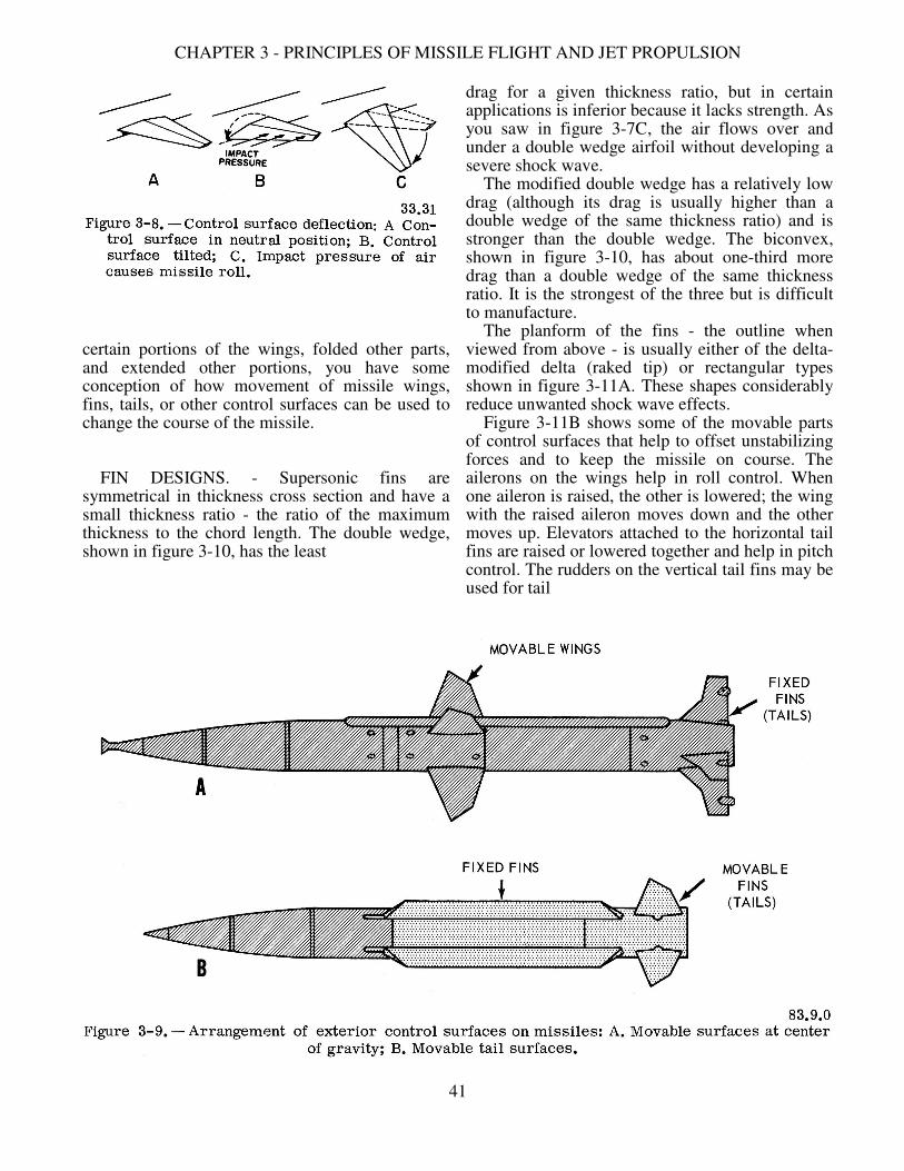
CHAPTER 3 - PRINCIPLES OF MISSILE FLIGHT AND JET PROPULSION
certain portions of the wings, folded other parts, and extended other portions, you have some conception of how movement of missile wings, fins, tails, or other control surfaces can be used to change the course of the missile. FIN DESIGNS. - Supersonic fins are symmetrical in thickness cross section and have a small thickness ratio - the ratio of the maximum thickness to the chord length. The double wedge, shown in figure 3-10, has the least
drag for a given thickness ratio, but in certain applications is inferior because it lacks strength. As you saw in figure 3-7C, the air flows over and under a double wedge airfoil without developing a severe shock wave. The modified double wedge has a relatively low drag (although its drag is usually higher than a double wedge of the same thickness ratio) and is stronger than the double wedge. The biconvex, shown in figure 3-10, has about one-third more drag than a double wedge of the same thickness ratio. It is the strongest of the three but is difficult to manufacture. The planform of the fins - the outline when viewed from above - is usually either of the delta- modified delta (raked tip) or rectangular types shown in figure 3-11A. These shapes considerably reduce unwanted shock wave effects. Figure 3-11B shows some of the movable parts of control surfaces that help to offset unstabilizing forces and to keep the missile on course. The ailerons on the wings help in roll control. When one aileron is raised, the other is lowered; the wing with the raised aileron moves down and the other moves up. Elevators attached to the horizontal tail fins are raised or lowered together and help in pitch control. The rudders on the vertical tail fins may be used for tail
41

GUNNER'S MATE M 3 & 2
control. If one rudder is moved to the right, the tail moves to the left and the missile yaws to the right. In most missiles in present use, the movements of the various parts are caused by the hydraulic system in the missile, which receives instructions electrically as to what moves are necessary to keep the missile on its course. The Bullpup missile uses a form of tab (fig. 3-11B) as a method of control. Some of the newer missiles combine two devices, such as an elevator and an aileron, into an elevon, which allows control of both pitch and yaw by a single control mechanism. ARRANGEMENT OF FINS. - Fins are mounted on the airframe in several arrangements, some of
which are shown in figure 3-12. The CRUCIFORM is the most popular tail arrangement. It is used in surface-to-air missiles. Both the INLINE and INTER-DIGITAL cruciform arrangements are widely used, especially for supersonic missiles. Control Surfaces, Internal We mentioned earlier that some missiles do not have external control surfaces such as wings, fins, and tails. They may have small control surfaces that must be supplemented by other means of control. Two types have been used as auxiliary controls-exhaust vanes and jet control. Exhaust vanes are control surfaces mounted directly in the exhaust path of a jet or rocket engine (fig. 3-13B). When the exhaust vanes are moved they deflect the exhaust, resulting in a change in the direction of thrust so as to keep the missile pointed in the desired direction. Even when the missile has just begun to move after launching, the exhaust velocity is very high. One disadvantage is that the tremendous heat of the exhaust makes the life of the vanes very short. The German V-2 missile used exhaust vanes of carbon; these lasted, on the average, about 60 seconds before they were burned up completely. Various forms of vanes are used and may be called jet vanes, jetevators, or jetevons. Some are fixed and some are movable.
42

CHAPTER 3 - PRINCIPLES OF MISSILE FLIGHT AND JET PROPULSION
Movable jets are another method of controlling the flight attitude of a missile. One method is to mount the engine itself in gimbals (fig. 3-13C), and turn the whole engine to deflect the exhaust stream. This system requires that the engine be fed with flexible fuel lines, and the control system that turns the engine must be very powerful. Also, it cannot control roll of the missile. To get control of all axes, two gimbal- mounted jets may be positioned in the missile. Both jets must be free to move in any direction, and must be able to respond to signals from any of the three control channels (pitch, roll, and
yaw). Another system uses four movable jets mounted in the aft end of the missile. Two jets control yaw, two control pitch, and all four together control roll. Sometimes a fifth jet is fixed in the middle, in the space between the movable jets. Fixed steering jets (fig. 3-13A) are placed around (inside) the missile so as to give directional control by exerting a force in one direction or another. Heat shields are necessary to protect the main body of the missile against the heat of exhaust from the jets. The use of these auxiliary jets makes it possible to eliminate all outside control surfaces. Missiles and spacecraft that reach into the higher, rare atmospheres, where external control surfaces are of little use, must depend on internal control means. MISSILE AIRFRAMES The airframe of a guided missile serves the same purpose as the airframe of the conventional aircraft: it carries the necessary components and controls to ensure proper flight. But, since the guided missile is essentially a one-shot weapon, the body structure can be simpler in structure than that of a conventional aircraft. Missile bodies are designed so that inner components are readily available for testing, removal, and repair. The major components are mounted to form independent units. Adequate room is provided to permit slack in electrical cables and harnesses so that inner sections can be removed easily during maintenance.
43

GUNNER'S MATE M 3 & 2
The configuration of a guided missile is the principal factor controlling the drag and lift forces that act on it as it passes through the atmosphere. Supersonic missiles must be designed for minimum drag. Both lift and drag are directly proportional to the square of missile speed. The shape of the nose, the body, and external control surfaces (if used) must be scientifically designed to obtain a maximum of lift and a minimum of drag. Another effect that must be considered in missile design is that of heat. Heat results not only from friction as the missile passes through the atmosphere, but also from the temperature rise caused by the ram effects as the air is compressed by the speeding missile. A significant part of the development effort for long-range ballistic missiles has been devoted to development of nose cones capable of withstanding extreme temperatures. Most missile bodies are slender cylindrical structures similar to those shown in figure 3-9. Several types of nose sections are used. If the missile is intended for supersonic speeds, the forward section may have a pointed arch profile in which the sides taper in lines called ogive curves (fig. 3-14A). Missiles which fly at lesser speeds may have blunt noses as shown in figure 3-14B. Rounded noses which house radar equipment may look like the one in figure 3-14C. Figure 3-14D shows an air-breathing missile nose which includes the duct for the ramjet propulsion system. The nose design of our ICBM has been modified several times, each one made to meet the need of the missile design with the least drag effect. Most modern missiles are made up of several sections. Each section is a cylindrical shell machined from metal tubing rather than a builtup structure with internal bracing. Each shell contains one of the essential units or components of the missile, such as the propulsion system, the electronic control equipment, the warhead, or the fuze assembly. Sectionalized construction has the advantage of strength with simplicity, and also provides ease in replacement and repair of the components since the shells are removable as separate units. The sections are joined by various types of connections designed for simplicity of operation. Access ports are sometimes provided in shells, through which adjustments can be made prior to launching.
MISSILE PROPULSION SYSTEMS Guided missiles must travel at high speeds to be effective. To reach high speeds, missiles use jet propulsion. This chapter will introduce the theory of jet propulsion and several types of propulsion systems. Before you can understand how jet propulsion works, you need to know the basic laws of physics that apply to gases and liquids; then you can see how they are applied in jet propulsion of missiles. GASES UNDER PRESSURE Before taking up propulsion systems, let us look at the way gases are affected by variations in pressure and temperature. As a Gunner's Mate (Missile) you will use pressurized gases in many ways. Gases at high temperatures and pressures are used in the main propulsion systems of missiles. These gases may be in the form of high pressure air (or other inert gases) stored in flasks, or in the form of fuel combustion products. From the safety standpoint it is especially important that you understand the theory of pressurized gases. Gases under pressure can be extremely dangerous if not handled in accordance with the applicable safety precautions. Many of these precautions will be presented later in this manual.
44
CHAPTER 3 - PRINCIPLES OF MISSILE FLIGHT AND JET PROPULSION
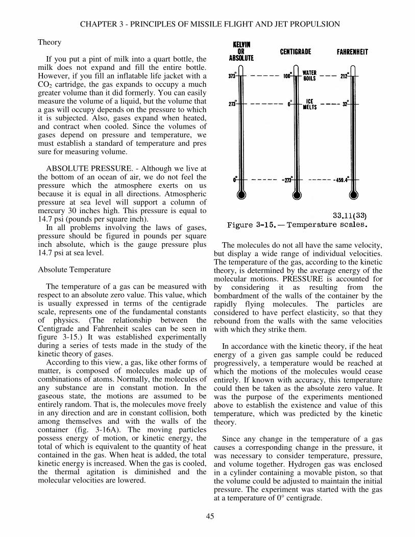
Theory If you put a pint of milk into a quart bottle, the milk does not expand and fill the entire bottle. However, if you fill an inflatable life jacket with a CO2 cartridge, the gas expands to occupy a much greater volume than it did formerly. You can easily measure the volume of a liquid, but the volume that a gas will occupy depends on the pressure to which it is subjected. Also, gases expand when heated, and contract when cooled. Since the volumes of gases depend on pressure and temperature, we must establish a standard of temperature and pres sure for measuring volume. ABSOLUTE PRESSURE. - Although we live at the bottom of an ocean of air, we do not feel the pressure which the atmosphere exerts on us because it is equal in all directions. Atmospheric pressure at sea level will support a column of mercury 30 inches high. This pressure is equal to 14.7 psi (pounds per square inch). In all problems involving the laws of gases, pressure should be figured in pounds per square inch absolute, which is the gauge pressure plus 14.7 psi at sea level. Absolute Temperature The temperature of a gas can be measured with respect to an absolute zero value. This value, which is usually expressed in terms of the centigrade scale, represents one of the fundamental constants of physics. (The relationship between the Centigrade and Fahrenheit scales can be seen in figure 3-15.) It was established experimentally during a series of tests made in the study of the kinetic theory of gases. According to this view, a gas, like other forms of matter, is composed of molecules made up of combinations of atoms. Normally, the molecules of any substance are in constant motion. In the gaseous state, the motions are assumed to be entirely random. That is, the molecules move freely in any direction and are in constant collision, both among themselves and with the walls of the container (fig. 3-16A). The moving particles possess energy of motion, or kinetic energy, the total of which is equivalent to the quantity of heat contained in the gas. When heat is added, the total kinetic energy is increased. When the gas is cooled, the thermal agitation is diminished and the molecular velocities are lowered.
The molecules do not all have the same velocity, but display a wide range of individual velocities. The temperature of the gas, according to the kinetic theory, is determined by the average energy of the molecular motions. PRESSURE is accounted for by considering it as resulting from the bombardment of the walls of the container by the rapidly flying molecules. The particles are considered to have perfect elasticity, so that they rebound from the walls with the same velocities with which they strike them. In accordance with the kinetic theory, if the heat energy of a given gas sample could be reduced progressively, a temperature would be reached at which the motions of the molecules would cease entirely. If known with accuracy, this temperature could then be taken as the absolute zero value. It was the purpose of the experiments mentioned above to establish the existence and value of this temperature, which was predicted by the kinetic theory. Since any change in the temperature of a gas causes a corresponding change in the pressure, it was necessary to consider temperature, pressure, and volume together. Hydrogen gas was enclosed in a cylinder containing a movable piston, so that the volume could be adjusted to maintain the initial pressure. The experiment was started with the gas at a temperature of 0° centigrade.
45

GUNNER'S MATE M 3 & 2
It was found that when the gas was cooled enough to drop the temperature by 1°C, the volume had to be decreased by moving the piston in order to keep the sample at the same pressure. The new gas volume was then equal to 272/273 the volume at 0°C. As the temperature was lowered further, the volume (for constant pressure) decreased by an amount equal to 1/273 the initial volume for each decrease of one centigrade degree. If, however, the volume was kept constant by keeping the piston unchanged in position, it was found that the pressure varied at the same rate. That is, it decreased by an amount equal to 1/273 the pressure at 0° C for each drop of 1 ° in the temperature.
The same rates of change of volume and pressure were found to be present in all gases; and they were uniform over a wide range of temperature. All these facts led to the conclusion that if any gas were cooled to -273°C (actually -273.16°), with the pressure kept constant, the volume would shrink to zero. However, all known gases change to the liquid state before this temperature is reached. Also, if the volume were maintained at the initial value, the pressure would approach zero as the temperature approached this same value. It was then assumed that -273°C represents the theoretical absolute zero point at which all molecular motion ceases, and no more heat remains in the substance. The existence of absolute zero cannot be determined directly by observing the volume
46

CHAPTER 3 - PRINCIPLES OF MISSILE FLIGHT AND JET PROPULSION
of gas cooled to -273°C, since all gases are converted to the liquid state before this temperature is reached. In many experiments, however, this condition has been approached closely, the actual temperature reached being within a small fraction of a degree of the theoretical zero value. THE KELVIN SCALE. - When temperatures are measured with respect to -273°C they are said to be expressed in the absolute, or Kelvin, scale. Specific absolute temperatures are designated by the letter K. Thus, 0° C is equivalent to 273° K, 20° C equals 293° K, and 100° C equals 373° K. The relationship between the three temperature scales is shown in figure 3-15. The Kelvin scale is used in scientific work. In formulas, Kelvin temperatures in general are represented by T and Centigrade or Fahrenheit temperatures by t. Gas Laws The natural laws that affect the behavior of gases were determined by experiments by scientists long ago. The first of these is Boyle's law (Robert Boyle, 1627-1691), which is stated as follows:
"The volume of any dry gas, the temperature remaining constant, varies inversely with the pressure on it; that is, the greater the pressure, the smaller the volume becomes."
Figure 3-16B illustrates this law, showing the volume halved when the pressure is doubled, where F represents force applied. In the second part of the picture, there are twice as many gas molecules per unit of volume (density is double), and twice as many collisions per second. This law may be stated as an algebraic formula:
V1 Pl = V2 P2 where V1 and P1 refer to the original volume and pressure, and V2 and P2 refer to the new volume and pressure. This equation is true only if the temperature has remained the same. Although this law was formulated for a perfect or ideal gas, it holds closely for ordinary gases except under high compression, when a modified equation is applied. A second gas law has to do with the effects of changes in temperature:
All gases expand and contract to the same extent under the same change of temperature, provided there is no change in pressure. In general, when the pressure is kept constant, the volume of a gas is proportional to its absolute temperature (Kelvin). This is known as Charles' law. See figure 3-16 C. It is also known as the Gay-Lussac law. In equation form this becomes:
V1 T1 ___ = ___ V2 T2
where V is the volume and T is the absolute temperature (Kelvin). Finally, since the volume of a gas increases as the temperature rises, it is reasonable to expect that if a confined sample of gas were heated, its pressure would increase. Experiments have shown that the pressure of any gas kept at a constant volume increases for each degree centigrade rise very nearly 1/273 of its pressure at 0° C. Because of this finding it is convenient to state this relationship in terms of absolute temperatures. For all gases at constant volume, the pressure is proportional to the absolute temperature. The first two formulas (Charles' law and Boyle's law) may be combined to give the general gas law, by which the effect may be computed of the variation of any or all of the three quantities - pressure, volume, and temperature - at the same time. It is not likely that you will have to perform computations with any of these formulas, but the effects of the gas laws influence your daily work. Although air is a mixture of gases, it obeys the same laws. You have just studied how changes in air density and pressure affect missile flight. The combustion gases formed by the burning propellant inside the missile respond to the same laws. Gases that you use in various ways in your work aboard ship, such as compressed air, oxygen, and carbon dioxide, conform to the gas laws. A number of the safety regulations are necessary because of the way these gases behave. You can see there are plenty of reasons why you should know how gases react to different situations.
PRINCIPLE OF JET PROPULSION. The principle of jet propulsion is based on Sir Isaac Newton's third law of motion which
47

GUNNER'S MATE M 3 & 2
states that "For every action there is an equal and opposite reaction." As an example of the reaction principle, remember your firefighting training in boot camp. You will probably recall your first experience with a large diameter high pressure firehose. With the hose pressurized and the nozzle closed, a single man can handle the charged firehose; but as soon as the nozzle is opened, two or three men are required. The reason for this is that as soon as water is permitted to escape from the nozzle, reaction to this water flow causes the nozzle to buck or kick in the opposite direction. The amount of reaction or "thrust" is equal to the force of the escaping water. This force can be determined by measuring the mass and velocity of the water which escapes. The two most common methods by which we produce thrust are by mechanical means (pumps or fans), and by thermal means (chemical reaction). The firehose is an example of a mechanical jet. Another example of the mechanical jet may be found in nature. The squid draws water into its body and then by muscle contraction forces this water rearward through a small opening at an increased velocity, thus propelling itself forward. In guided missiles we are concerned with thermal jets - those that operate by reaction to the exhaust of combustion gases. It is a common misconception that a jet engine is dependent on the atmosphere to obtain its thrust,
or force, in the direction of motion. (Air- breathing jets require air for oxygen to support combustion of the propellant.) Actually, thrust is the reaction to the ejection of exhaust gases. If you take a firehose and direct the water stream against a wall, the reaction force experienced is the same as if the wall were not there. To continue the analogy, missile thrust is the same regardless of whether the missile is in the atmosphere or in the vacuum of space. Jet engines are frequently called reaction motors, since the exhaust gases produce the action while the opposite motion of the missile or aircraft represents the reaction. Figure 3-17 charts the types of jet propulsion systems. The systems falling under the heading of rockets are those which carry within themselves all the materials necessary for their operation. In most rockets these materials include an oxidizer. An oxidizer is a substance which contains the oxygen necessary to support combustion of the fuel. (You will remember that a rocket was defined earlier as a missile with an independent propulsion system.) Rockets are sometimes referred to as air-independent units, since they do not rely on the oxygen in the atmosphere. The atmospheric jets, on the other hand, depend on air to support combustion. Both the rocket and the atmospheric jet receive their thrust as a reaction to the exhaust of combustion gases.
48

CHAPTER 3 - PRINCIPLES OF MISSILE FLIGHT AND JET PROPULSION
It should be remembered that the rocket is the only jet engine capable of operating outside the earth's atmosphere. Present day surface-to-air missiles have either ramjet or solid propellant propulsion systems. In this section we will discuss only these two types. COMPONENTS OF JET PROPULSION SYSTEMS
To achieve high thrust, it is necessary to produce large quantities of exhaust gases at high temperatures and pressures. To produce these exhaust gases, jet propulsion systems consist of a combustion chamber, an exhaust nozzle, and a fuel supply. Combustion Chamber
The combustion chamber is that part of the system in which the chemical action (combustion) takes place. Combustion is necessary to provide thrust. Useful thrust cannot be attained in an atmospheric jet unless the combustion products are exhausted at a velocity greater than that of the intake gases (air). The chamber is usually called a cylinder, although it may have the shape of a sphere. It must have the proper length and diameter to produce a chamber volume suitable for complete and stable combustion. In all thermal jets, the heat energy released by the combustion process is converted to kinetic energy through expansion of the gases of combustion as they pass through the exhaust nozzle. Exhaust Nozzle
An exhaust nozzle is a nonuniform chamber through which the gases generated in the combustion chamber flow to the outside. Its most important areas are the mouth, throat, and exit. These areas are identified in figure 3-18. The function of the nozzle is to increase the velocity of the gases. The principle involved was announced many years ago by a Swiss physicist, Daniel Bernoulli. Bernoulli's principle applies to any fluid (gas or liquid). It may be stated as follows: "Provided the weight rate of flow of a fluid is constant, the speed of the fluid will increase where there is convergence in the line. It will decrease where there is a divergence in the line." Figure 3-19 illustrates this principle. The velocity of the fluid will increase at point 1. At the point of divergence, point 2, the speed of the fluid will decrease.
The increase in speed between points 1 and 2 is caused by a conversion of potential energy (fluid pressure) to kinetic energy. Thus, the pressure drop of the fluid through the restriction is proportional to the velocity gained. When the fluid reaches point 2, the kinetic energy is again converted to potential energy. At point 2, the fluid velocity decreases, and the pressure of the fluid increases. This relationship also holds true for subsonic flow of gases. In the convergent nozzle in figure 3-20A, the speed will increase up to the speed of sound, depending on the degree of convergence. In the divergent nozzle in figure 3-20B, gases at subsonic speeds will slow down, depending on the degree of divergence. Gases at supersonic (faster than sound) speed behave differently. As these gases pass through the divergent nozzle, their velocity is INCREASED because of their high state of compression. The drop in pressure at the point of divergence causes an instantaneous release of kinetic energy. This imparts additional speed to the gases. To obtain supersonic exhaust velocity, the DeLaval nozzle in figure 3-20C is commonly used. This nozzle
49

GUNNER'S MATE M 3 & 2
first converges to bring the subsonic flow up to the speed of sound. Then the nozzle diverges, allowing the gases to expand and produce supersonic flow. The Prandtl nozzle (fig. 3-20D) is more efficient than the straight-coned DeLaval nozzle but is more difficult to engineer and produce. It increases the rate of flow at a higher rate than the normal convergent-divergent type. The shape of the nozzle determines the characteristic of the gas flow, which must be smooth. Other nozzles of increasing importance are the adjustable area type, in which the nozzle area is varied to suit varying combustion environmental conditions. The best size for the nozzle throat is different for different propellants. The nozzle must be designed for a specific set of propellant and combustion characteristics to obtain higher velocity and increased thrust. Fuel Supply The fuel supply consists of solids, liquids, gases, or various combinations of these. However, fuels in the gaseous state are rarely us~ in missiles. Liquids or solids have a higher density than most gases, even when the latter are highly compressed; thus a larger quantity of solid or liquid fuel can be carried in a given space. Many factors must be considered when selecting the fuel or fuels to be used in a certain missile. Among these factors are cost, availability, safety, ease of handling and storage, storage life, and amount of "push" it will furnish to the missile. ROCKET FUELS. - Several means have been worked out for rating, or comparing, various rocket fuels (propellants). Comparison is made by determining total impulse. Total impulse is the product of the thrust in pounds times burning time in seconds. Or, IT (Total Impulse in lb-sec) = T (Thrust in lbs) x t (Duration in secs). Solid propellants are rated, or compared, on the basis of specific impulse. Specific impulse is the amount of impulse produced by one pound of the propellant. Stated in formula: Isp (Specific Impulse in lb-sec/lb) = IT (Total Impulse in lb-sec) W (Weight of Solid Fuel in lbs)
50

CHAPTER 3 - PRINCIPLES OF MISSILE FLIGHT AND JET PROPULSION
A common method of comparing liquid propellants is on the basis of specific thrust. Specific thrust is equivalent to specific impulse [or solid propellants but derived in a slightly different way. Specific thrust is defined as the thrust in pounds divided by the rate of fuel now in pounds per second. Or, Tsp (Specific Thrust in lbs/lb/sec) = _________T (Thrust in lbs)__________ W (Weight Rate of Flow in lb. per sec) Specific thrust is expressed in seconds. You sometimes may see the term "specific impulse" used for liquid as well as solid propellants. However, the term "specific thrust" more correctly brings out the correct meaning for liquids. As for solid propellants, it would be impractical to attempt to measure the weight rate of flow; therefore, specific impulse is used for comparison of solid fuels. Specific propellant consumption is another term of importance in liquid propellant systems. [t is the reciprocal of specific thrust. It is defined as the propellant flow in pounds per second necessary to produce one pound of thrust. Or, Specific Propellant Consumption = Weight Rate of Flow (lbs/sec) Thrust (lbs) Other terms you should know are mixture ratio and exhaust velocity. Mixture ratio designates the relative quantities of oxidizer and fuel used in the propellant combination. It is numerically equal to the weight of oxidizer flow divided by weight of fuel flow. (Many liquid propellants are stored in separate containers, one holding the oxidizer, the other containing the fuel, until the moment of use.) Exhaust velocity is determined theoretically on the basis of the energy content of the propellant combination. The actual velocity of the exhaust gases is of course less than this theoretical value since no jet engine can completely convert the energy content of the propellant into exhaust velocity. Thus, effective exhaust velocity is sometimes used and is determined on the basis of thrust and propellant flow: Effective Exhaust Velocity = ______Thrust (lbs)_______ Mass Rate of Flow (lbs/sec)
Solid Propellants The ingredients of a solid propellant are mixed so as to produce a solid of specified chemical and physical characteristics. Some examples of materials used in making solid propellants are asphalt-oils, nitroglycerin, asphalt-potassium perchlorates, black powder with ammonium nitrate, and other recently developed combinations. The finished product takes the shape of a grain, or stick. A charge may be made up of one or more grains. Do not think of a grain of propellant as the size of a grain of sand or a grain of wheat. It may be that small, but it may be several feet long, see figures 3-30 and 3-31. Combustion of solid propellants will be discussed later in this chapter. An ideal solid propellant would: 1. Have a high specific impulse. 2. Be easy to manufacture from available raw materials. 3. Be safe and easy to handle. 4. Be easily stored. 5. Be resistant to shock and temperature. 6. Ignite and burn evenly. 7. Be non-water-absorbent. 8. Be smokeless and flashless. 9. Have indefinite service life. It is doubtful if a single propellant having all of these qualities will ever be developed. Some of these characteristics are obtained at the expense of others, depending on the performance desired. Liquid Propellants The liquid propellants are classified as monopropellants or as bipropellants. Monopropellants are those which contain within themselves both the fuel and oxidizer, and are capable of combustion as they exist. Bipropellants are those in which the fuel and oxidizer are kept physically separated until they are injected into the combustion chamber. An example of a monopropellant would be the mixture of hydrogen peroxide and ethyl alcohol; an example of bipropellant would be liquid oxygen and kerosene. While solid propellants are stored within the combustion chamber, liquid propellants are stored in tanks and injected into the combustion chamber. In general, liquid propellants provide a longer burning time than solid propellants.
51

GUNNER'S MATE M 3 & 2
They have a further advantage in that combustion can be easily stopped and started at will by controlling the propellant flow. When oxygen or an oxygen-rich chemical is used as an oxidizer, the best liquid fuels appear to be those rich in both carbon and hydrogen. In addition to the fuel and oxidizer, a liquid propellant may also contain a catalyst to increase the speed of the reaction. A catalyst is a substance used to promote a chemical reaction between two or more other substances. Inert additives, which do not take part in the chemical reaction, are sometimes combined with liquid fuels. An example is water, which is often added when alcohol is used as a fuel. Although the water does not take part in the chemical reaction, the water does provide additional particles which contribute to a higher thrust by increasing the rate of mass flow through the system. An ideal liquid propellant would: 1. Be easy to manufacture from available raw materials. 2. Yield a high heat of combustion. 3. Have a low freezing point. 4. Have a high specific gravity. 5. Have low toxicity and corrosive effects. 6. Have stability in storage. As with the solid propellants, it is unlikely that all of these characteristics can be combined in a single fuel. One that has a high specific thrust may be very toxic and therefore dangerous and difficult to handle. Another may be very unstable and difficult to store. Liquid oxygen is an example - it must be kept in high pressure tanks until just before launching. In spite of the best care, there is a large loss by evaporation while transferring the oxygen to the missile. No "best" propellant has been discovered. ATMOSPHERIC JETS As mentioned previously, the atmospheric jet relies on the surrounding atmosphere for oxygen to support combustion. Ramjets fall under the category of atmospheric jets. The first successful application of atmospheric jets to missile propulsion was the pulsejet engine used in the German V-I missile, the "buzz bomb" of World War II. It was so called because of the intermittent or pulsating combustion process. An early U. S. Navy missile used a pulsejet engine, but it is now considered obsolete.
Another form of atmospheric jet is the turbojet. It is not used in any Navy missiles at present but is used in some aircraft. Three Air Force missiles are turbojets - Matador, Mace, and Hound Dog. Future inventions may make the turbojet principle applicable to high speed missiles as well as to aircraft. Ramjet Engine The ramjet shown in figure 3-21 is an atmospheric jet which is essentially a pipe open at both ends. From this the term "flying stove pipe" originated. The principal parts of this engine are the diffuser, the combustion chamber and associated fuel-feed system, and the exhaust nozzle. The combustion process in the ramjet is continuous rather than intermittent as in the, pulsejet. The ramjet has no bank of valve, to restrict the flow of gases to one direction For this reason, the ramjet must be boosted to a speed very near its operating speed before. it takes over on its own. To attain this speed a rocket or other type of booster is used, an. it is generally larger and heavier than the ramjet itself. The Talos missile for example has a ramjet sustainer. This engine is ideally suited to long range high-speed missiles, since the thrust increase: with speed, and the rate of fuel consumption per unit of thrust decreases with speed. In other words, the faster a ramjet flies, the greater it efficiency. The ram action of the air increases with the speed of the missile. OPERATING CYCLE. - The cycle of subsonic ramjet operation is as follows (fig. 3-22A) 1. The ramjet is boosted by a separate propulsion unit to the required velocity. Ail enters the diffuser inlet and, due to the increasing cross section, decreases in velocity as it approaches the after end of the diffuser (an application of Bernoulli's principle). 2. This decrease in velocity is accompanied by an increase in pressure, with the result that a relatively high pressure barrier exists at the after end of the diffuser. 3. Fuel, usually kerosene, is sprayed into the combustion chamber through injection nozzles. 4. This fuel, thoroughly mixed with the incoming air, is ignited by a spark plug. 5. The combustion gases tend to expand in all directions.
52

CHAPTER 3 - PRINCIPLES OF MISSILE FLIGHT AND JET PROPULSION
6. Expansion in the forward direction is restricted by the pressure barrier existing at the after end of the diffuser; consequently, the gases must expand down the tailpipe and leave the exhaust nozzle with a greater velocity than that of the air at the intake. Once ignition takes place, there is no further need for an electric spark because combustion is continuous as long as the air-fuel mixture is maintained with proper limits. The flame holder (figs. 3-22A, B, C), prevents the flame from being blown too far to the rear of the engine. Without it, the flame could be blown out by the high speed air stream. The diffuser design is very important since a higher pressure barrier results in greater thrust. The operation of a supersonic ramjet (figs. 3-22B and C) is the same as that of a subsonic ramjet, with the following exceptions. First, the supersonic jet must be boosted to a supersonic speed. Second, a higher pressure barrier exists in the supersonic engine, resulting in greater thrust. Talos missiles have supersonic ramjet propulsion systems. Note the differences in the shape of the diffuser section and the throat in figure 3-22. They must be designed for a predetermined missile speed, according to Bernoulli's principle. Note, too, that the fuel injection systems can be varied. The effect of the shape of the exit nozzle on the speed of the exhaust gases is also illustrated. Compare the nozzles in figure 3-22 with those in figure 3-20.
ROCKETS Present day operational rockets may be divided into two classes - solid propellant and liquid propellant. The more important characteristics of all rocket engines are: 1. The thrust of a rocket is nearly constant, and is independent of speed. 2. Rockets will operate in a vacuum. 3. Rockets have relatively few moving parts. 4. Rockets have a very high rate of propellant consumption. 5. Burning time of the propellant in a rocket is short. 6. Rockets need no booster. They have full thrust at take off; therefore, when rockets do employ boosters it is for the purpose of reaching a high velocity in minimum time. Solid Propellant Engines The combustion chamber of a solid propellant rocket contains the charge of solid propellant. Solid propellant charges are of two basic types: restricted burning and unrestricted burning (fig. 3-23). The restricted burning charge is designed so that burning is permitted on only one surface at a time. A common example of restricted burning is a lighted cigarette. The restricted burning charge provides relatively low thrust and long burning time. Uses of this type of charge include JATO (jet-assisted take off) units, barrage rockets, and sustaining rockets for guided missiles.
53

GUNNER'S MATE M 3 & 2
54

CHAPTER 3 - PRINCIPLES OF MISSILE FLIGHT AND JET PROPULSION
A modification of the restricted burning charge is the bored restricted charge. The main difference is that the longitudinal hole in the charge provides somewhat more burning surface and thus a higher thrust and shorter burning time. In the unrestricted burning charge, burning takes place on several surfaces at one time. This results in a very high thrust during a short burning time. This type of charge is commonly used in booster rockets. It should be clearly understood that in both the restricted and unrestricted burning charges, the burning rate is controlled - there is no explosion. Controlling the burning rate of a solid propellant has always presented a problem to rocket designers. You will recall that one of the properties of an ideal solid propellant would be that it ignite and burn evenly. The burning rate may be controlled in several ways. One is by means of inhibitors. An inhibitor is any substance which interferes with or retards combustion. The lining and washer shown in figure 3-23 are examples of inhibitors. Another way that burning is controlled is by use of various grain shapes. Examples are the shapes shown in the lower part of figure 3-23. Resonant burning or "chugging" may be offset by the use of resonance rods. There metal or plastic rods are sometimes included in the combustion chamber to break up regular fluctuations in the burning rate and their accompanying pressure variations. The purpose of the various designs is to maintain
a constant burning area while the surface of the grain is being consumed. To start the combustion process, some form of electrically detonated squib is ordinarily used to ignite a smokeless or black powder charge. Upon igniting, the black powder charge provides sufficient heat and pressure to raise the exposed surface of the propellant grain to a point where combustion will take place. Until fairly recently, a serious disadvantage of the solid propellant had to do with the problem of dissipating the extreme heat of combustion. One way this has been overcome to a considerable extent is by use of the internal burning grain. Since the burning process actually takes place within the grain, the outer portion of the grain provides a shield between the intense heat and the combustion chamber wall until the grain is almost completely consumed. Solid propellant rockets are particularly adaptable to shipboard use. They are easily stored and ready for immediate use. So great have been the improvements in solid propellants in the past few years that they are now used in such missiles as the Navy's Polaris, Tartar, Standard, and Terrier, and the Air Force's Minuteman. Liquid Propellant Rockets You know from your reading of the newspapers that liquid fuel is used in space vehicles and satellites and that this fuel is put into the tanks of the space vehicles immediately before launching. A missile cannot wait to be fueled when it is needed for defense or offense-it must be ready. That is one of the reasons why solid propellants have replaced liquid propellants in most of our missiles. COMPONENTS OF LIQUID-FUEL ROCKETS. - The major components of a liquid-rocket system are the propellant, propellant-feed system, combustion chamber, igniter, and exhaust nozzle. The feed systems may be of the pressure-feed type or the pump-feed system, in which air or some other gas (preferably inert) is stored under pressure in the accumulator of the missile and is used to force the proper amounts of propellant and oxidizer into the combustion chamber when the rocket is fired. Generated-pressure feed systems contain substances, carried in the missile that generate high-pressure gas as needed. An example is hydrogen peroxide, which, when passed through a catalyst, decomposes to form a high pressure vapor. This vapor is then injected
55

GUNNER'S MATE M 3 & 2
into the storage tanks to force the propellant into the combustion chamber. Many other devices, such as valves, regulators, deli very tubes, and injectors, are necessary for the operation of either system. Pump-feed systems are used in those missile rocket motors which are designed to burn large volumes of propellants and in power plants requiring a high rate of flow. A pump-feed system consists of a fuel pump and an oxidizer pump. Each pump is driven by a turbine wheel. Power for, the wheel may be developed by chemical gas or by the rocket's exhaust gases. The auxiliary devices and controls required by a pump-feed system are far more complicated than for a stored-pressure system and a complicated checkout is required. PREPACKAGED LIQUID-FUEL ENGINES. - The Bullpup missile can use a prepackaged liquid-fuel engine. The first trials were made with the prepackaged version used in place of the regular solid propellant in Bullpup A, and can still be so used. It is the standard fuel package for the Bullpup B. The propellant and the oxidizer are in separate containers until the missile is fired, when the two liquids are mixed in controlled quantities and combustion occurs upon contact. The containers are designed so accidental mixing cannot occur. The success of the prepackaged method in the Bullpup missile gives the advantages of a liquid propellant without its disadvantages. Research is continuing in the development of high power fuels that meet the requirements for storability, safety, and cost. HYBRID PROPULSION A hybrid engine combines the use of liquid and solid propellants. The liquid is the oxidizer and the solid is the propellant. Neither will support combustion by itself in the hybrid engine. Ignition is usually hypergolic, that is, spontaneous ignition takes place upon contact of the oxidizer with the propellant. The combustion chamber is within the solid grain, as in a solid-fuel rocket; the liquid portion is in a tank with pumping equipment as in a liquid-fuel rocket. This type is sometimes called a forward hybrid to distinguish it from a reverse hybrid, in which the oxidizer is solid and the fuel is liquid. Combustion takes place on the inside surface of the solid fuel, after the liquid fuel is injected, and the combustion products are exhausted through the nozzle to produce the thrust as in other
rockets (fig. 3-24). Nozzle systems and control methods are the same as in other reaction engines. It is possible to start, stop, and restart the system as in a liquid fuel system by shutting down or I' reopening the liquid oxidizer flow system. Missiles such as the Talos, which has a solid-fuel booster and a liquid-fuel sustainer, are not hybrid systems; the liquid and the solid propellants do not interact. The hybrid system has several advantages on either solid or liquid systems by combining the advantages of both. At present we do not have an operational hybrid propulsion missile, but research and development are continuing. FEATURES OF SURFACE-TO-AIR MISSILES
Now that you have a little background in missile flight and propulsion principles, we will relate what you have studied to specific Navy surface-to-air missiles (RIMs: see chapter 4). At this writing there are four types of operational missiles: Talos, Terrier, Tartar and Standard. As a GMM you will maintain launching system equipment that stows, handles, and launches Talos, Terrier, Tartar and Standard missiles. Therefore, we will cover briefly some of the characteristics and features of these missiles. Coupled with your launching system maintenance duties, you will help handle and maintain missiles. The more you know about the missile you are working with, the better you can do your job. TALOS MISSILE ROUND Figure 3-25 shows you what a Talos missile looks like. It is the largest of the RIMs. Notice that it is made up of two sections or stages. The first stage is the booster; the second stage is the missile proper. These two sections, when they are connected, form what is called a complete round, weapon, or missile booster combination. You will see the terms used interchangeably. First, consider the missile section. It only takes a quick glance at figure 3-25 to see that Talos is a ramjet propelled missile. The clue to recognizing it as a ramjet is the diffuser opening in its nose (fig. 3-14). Four raked-tip biconvex (figs. 3-10, 3-11) wings steer the missile. The wings are located near the missile's center of gravity. Four fixed rectangular fins are attached near the end of the missile. Like the wings, they are biconvex. Both wings
56

CHAPTER 3 - PRINCIPLES OF MISSILE FLIGHT AND JET PROPULSION
57

GUNNER'S MATE M 3 & 2
and fins are arranged in a cruciform pattern about the missile body (fig. 3-12). The wings and fins are in line with each other. Now. look at the booster. You learned earlier that the purpose of a booster is to propel the missile to flight speed. Talos has a ramjet sustainer, and it operates most efficiently in the supersonic range. The Talos booster is a solid propellant rocket unit. Basically, it consists of the propellant, combustion chamber (called the case), igniter assembly (includes arming and disarming mechanisms), and exit nozzle. The booster case is a long, round, metal tube. It serves two purposes. First, it acts as a storage place for the propellant, and second, it serves as a chamber in which solid propellant burning takes place. The propellant consists of nitrocellulose explosive and a metal compound. These materials are mixed together to make an even burning grain. The grain is star shaped. When propellant grains are shaped in this fashion, many constant burning surfaces are provided. The booster produces a large amount of thrust for a short time - in the order of 4 or 5 seconds. To reduce chugging, resonance rods are placed along the length of the grain. The rods absorb vibrations set up in the combustion chamber. The front end of the booster is enclosed by a metal cap. The cap supports the igniter assembly. The igniter consists of a small charge of pyrotechnic material and several electrical squibs. When current flows through the squibs the pyrotechnic material starts burning. The material generates enough heat and flame to ignite the main rocket propellant. Another unit attached to the head cap is the booster arming-disarming device. Its purpose is to mechanically open and close that portion of the booster firing circuit that is in the booster igniter. The rest of the firing circuit is in the launching system. (We'll cover firing circuits in detail in chapter 9 of this manual.) Boosters are in the disarm (safe) condition while they are in stowage. They are not armed until they are ready to be launched. Then they are armed by a mechanical device (called an arming tool) on the launcher. A clamping arrangement on the head cap connects the missile and its booster. When the booster burns out, the clamp is released and the booster falls away from the missile. Then the missile continues on its way under its own sustainer power.
An exit nozzle is at the after end of the booster case. It compresses the propellant gases as they escape through the opening in the nozzle. The nozzle is a convergent-divergent (fig. 3-20) type. The nozzle also provides a foundation for the four fixed fins. The only continuous physical contact the Talos round has with its launcher is through the top set of shoes. These hooklike metal lugs are solidly attached to the booster case. And they fit into slots cut into the launcher's guide rails. Igniter firing contacts are located on the forward top shoe. The bottom set of shoes are used to handle the weapon. By handling we mean the operations and steps involved in stowing the weapon and loading it on the launcher. TERRIER GUIDED MISSILE ROUND Terrier is the name applied to a large family of missiles. The most obvious common feature of Terrier missiles is that each type has a separate booster. Some Terriers have movable tails; others have movable wings near the missile center of gravity to do the steering job. The tail controlled missiles have fixed fins that resemble the dorsal fins of a sail fish or marlin. The earliest Terriers put aboard ship were the wing-controlled BW-O and BW-l. They are now obsolete as weapons but may be used as target drones. The beam-riding, tail-controlled missile, designated the BT-3 (B for beam-riding the T for tail-controlled) was next to be tested and improved. The improvements included the BT-3A and the BT-3B, each of which had a choice of warheads. These, too, are no longer being produced, but there are some around. In the next chapter we will briefly cover the rest of the Terrier family and point out the similarities and differences between members. Now then, look closely at figure 3-26. It shows the general outline of the BT-3 and its booster. Variations in the mods of the BT-3 will not be discussed here. Let's start at the nose of the BT-3 and work aft. The nose has an ogival shape, which is a characteristic of most supersonic missiles. Four fixed dorsal fins are attached to the missile in cruciform arrangement. They stabilize the missile and provide some lift. Four control surfaces, called tails, steer the missile and keep it from rolling. Another feature of the tails is that they can be folded. This cuts down on the space needed for stowage, and makes handling
58

CHAPTER 3 - PRINCIPLES OF MISSILE FLIGHT AND JET PROPULSION
easier. Before a missile is put on its launcher, the tails are manually unfolded. Notice the clamp ring between the end of the missile and the head of the booster. The clamp holds them together. For the present, we'll leave the missile, and return to it in chapter 4. Now consider figure 3-27. It shows a cutaway drawing of the BT-3 booster. The drawing is simplified but shows all the booster's essential parts. The booster is basically a round steel shell, closed at the forward end and open at the after end. Four fixed fins (not shown in fig. 3-27) are attached to the after end of the booster. The fins simply help stabilize the complete round during the boosted part of the missile's flight. Notice the shoes at both ends of the booster. The top set is used to hang the missile from the launcher. The bottom set is used for handling the missile. The booster and missile are held together by a mechanical clamping device attached to the forward end of the booster. An electrical connection is also made between missile and booster. The booster igniter is in the forward end of the booster, and is wired to contacts on the upper forward shoe. Booster ignition current is applied from the launcher to the pair of shoe contacts and then to the igniter squibs. On the top forward part of the booster you can see an electrical receptacle (pad). It receives a hydraulically operated contactor which extends from the launcher and jabs into the pad. It can also be retracted. (More about this in chapter 6.)
The separation action of booster from missile is extremely crucial. It must take place very quickly and smoothly so as not to disturb the flight of the missile. Many other factors must be calculated by the designers to/ achieve successful separation of missile and booster in flight. The HT-3 Terrier Missile In outward appearance, the HT-3 missile is much like the BT-3. Figure 3-28 shows the exterior of the HT-3 and the BT-3 for comparison, and indicates the location of the main components of each. The booster is not shown; all mods of the BT-3 and the HT-3 can use the same booster. Much of the actual hardware is the same in the BT-3 and the HT-3. The booster (mentioned above), the sustainer, and the aft section are identical. The big difference is in the method of guidance used. All mods of the BT-3 missile are beam-riders, while the HT-3s are homing missiles. Semi active homing is the type usually used, but some mods have the capability of switching to passive type of homing. Guidance methods are discussed in the next chapter. With a homing missile, its target seeker is in the nose, or forward end of the missile. A radome encloses the instruments to provide a streamline shape to the missile; it is transparent to radar waves, which the missile must receive and interpret in order to locate the target.
59

GUNNER'S MATE M 3 & 2
Additional differences and similarities are pointed out in chapter 4. TARTAR MISSILE ROUND Tartar does not have a separate booster. The missile comes all in one piece as you can see in figure 3-29. Instead of a separate booster, it has what is called a dual thrust rocket motor (DTRM). The DTRM has two propellant grains: one to boost the missile to flight speed, and one to keep it flying at this speed.
The Tartar missile looks just like the HT-3 Terrier, though it is considerably longer, so we won't dwell on Tartar's physical appearance. Briefly, it is round, with an ogival nose. Four fixed dorsal fins are in line with four independently movable tails. Unlike the other two missiles you must read about, Tartar is designed to fly in either of two flight positions. Figure 3-30 shows a cutaway view of the DTRM. You will notice that it has all the parts that Terrier and Talos boosters have. There
60

CHAPTER 3 - PRINCIPLES OF MISSILE FLIGHT AND JET PROPULSION
is a booster igniter, and an igniter arming- disarming device. An arming tool on the Tartar launcher mechanically arms or disarms the igniter circuit. Firing contacts on the missile skin scrape contacts on the launcher to complete the missile-to-launcher part of the firing circuit. The warmup pad is not located in the same place as on Terrier and Talos, but on the after face of the steering and power section. This section fits around the tail pipe and is indicated by the broken lines in figure 3-30. The warmup pad has the same function, of course, as the pads on Talos and Terrier - to provide an external warmup power connection.
The Tartar propulsion unit is unique because it has two separate grains in its propulsion system. Figure 3-31 shows a cross- sectional view of the DTRM as seen from the end of the missile. The steering and control section have been removed. You can see that the two grains are cast in a concentric grain design-the sustainer grain encloses the inner booster grain. There are no resonance rods because the grains burn so smoothly that chugging does not happen. The inner, or booster part of the DTRM is a fast-burning type of propellant and burns first and then the slower burning propellant in the sustainer portion takes over to furnish the thrust during the main part of the missile's flight. Several advantages of dual-thrust rocket motors over separate boosters are: 1. There is no empty booster case to get rid of. Sometimes booster cases fail to separate from the missile, clamping devices fail to operate, or, during handling the booster and missile are tightly jammed together. Another problem caused by empty boosters is related to safety. Care must be taken to keep a booster from falling on another ship. The booster splash point (the area in the sea where the empty case will hit at the end of its fall) must be predicted. This requires extra computing equipment on board ship. 2. Heavy power-driven equipment is needed to hold and to move the missile and separate booster during the mating operation. These equipments are not required for single-stage missiles.
61

GUNNER'S MATE M 3 & 2
STANDARD MISSILE ROUND Figures 3-32 and 3-33 show the configuration of the Standard missiles. There are two versions of the Standard missiles: RIM-66A is a Medium Range (MR) missile and RIM-67A is an Extended
Range (ER) missile. Both configurations are surface-launched, supersonic guided missiles that may be used against surface or air-borne targets. Both the ER and MR missiles are cylindrical with a VonKarman-shaped radome, and four dorsal fins located in line with four independently movable tails. The tails and fins are numbered in the same manner as Terrier and Tartar. The MR version, fig. 3-32. is launched and propelled by a dual thrust rocket motor (based on the same concept as Tartar). It consists of two propellant grains (similar to the Tartar DTRM, fig. 3-31) cast concentrically in a steel shell which is closed at the forward end and terminated at the aft end with an extension tube and expansion cone. As the booster is consumed, the sustainer (outer) grain is ignited and provides the thrust necessary to maintain velocity acquired during the boost phase. The ER version, fig. 3-33, is launched and propelled in two stages by a solid fuel rocket motor (booster and sustainer). The booster is a cylindrical rocket motor consisting of a dual- propellant grain housed in a steel shell which is terminated at the aft end in a nozzle and closed at the forward end by an adapter assembly. When ignited, the booster grain provides the initial thrust necessary to accelerate the ER missile to supersonic velocities. The sustainer is a cylindrical rocket motor consisting of a propellant grain housed within a steel shell which is closed at the forward end and terminated at the aft end with a nozzle assembly. An in-flight arming-firing device if armed by acceleration during the boost phase
62

CHAPTER 3 - PRINCIPLES OF MISSILE FLIGHT AND JET PROPULSION
and thereafter, upon receipt of firing voltage, ignites the igniter train. The sustainer provides the necessary thrust to maintain the velocity acquired during the boost phase. The guidance system of the ER and MR missiles operates as either a semiactive or passive homing guidance system. Roll stabilization and steering are accomplished by the movement of four aerodynamic control surfaces (tails). Guidance systems are discussed more in detail in chapter 4. Missile operating power is provided by the primary battery which consists of two electric ally separate cell packs (electronic battery and electromechanical battery) and an activator assembly. The electronic cell block supplies power to signal and low power level circuits. The electromechanical cell block supplies power to major power consumption circuits. Both cell packs are of the silver zinc type and are inactive until filled (at launch) with the electrolyte contained in the activator assembly. Battery power eliminates
the need for hydraulics and for power conversion during flight. CONCLUSION The material in this chapter will be extremely valuable to you in your duties as a Gunner's Mate Missile. An understanding of aerodynamics, the jet propulsion theory, the gas laws, and the various basic missile propulsion systems will help you to realize why missile launching systems and missile magazine spaces are designed as they are. Much of the information covered will also relate directly to the operational aspects of missile launching systems. The next chapter of this manual will take up missile guidance - that is, it will discuss the basic components of guided missiles which enable them to alter their trajectories and collide with moving targets. We'll also have more to say about Talos, Tartar, Terrier, and Standard missiles.
63


![Gas Dynamics and Jet Propulsion[May2012]](https://img.dokumen.tips/doc/110x75/55cf9202550346f57b92b3ed/gas-dynamics-and-jet-propulsionmay2012-5611878777c5f.jpg)