Embed Size (px)
Citation preview

Principles for Best Practice Geomechanics for CCS Injection Operations and its Application to the CarbonNet Project.

Disclaimer This publication may be of assistance to you but the State of Victoria and its employees do not 14Tguarantee14T that the publication is without flaw of any kind or is wholly 14Tappropriate14T for your particular purposes and therefore disclaims all liability for any error, loss or other consequence which may arise from you relying on any information in this publication
The material and information contained in this publication is made available to further the Global CCS Institute’s objective of accelerating the global adoption of safe, commercially and environmentally sustainable carbon capture and storage technologies in the public interest and is provided for convenience only. The Global CCS Institute, state, and any third parties who have contributed to the publication, do not give any representation or warranty as to the reliability, accuracy or completeness of the information, nor do they accept any responsibility arising in any way (including by negligence) for errors in, or omissions from, the information. No persons should act or fail to act on the basis of these materials
To the maximum extent permitted by law, the Global CCS Institute, state and any third parties who have contributed to this publication, disclaim all liability for any loss, damage, expense and costs incurred by any person arising out of using or relying on any material and information contained in this publication.
January 2017
© The State of Victoria 2017
This publication is copyright. No part may be reproduced by any process except in accordance with the provisions of the Copyright Act 1968.
Authorised by the Department of Economic Development, Jobs, Transport and Resources
Acknowledgement The CarbonNet Project receives funding from the Australian and Victorian Governments as part of the Carbon Capture and Storage Flagships program.
The preparation of this paper is part of a funding agreement between the CarbonNet Project and the Global Carbon Capture and Storage Institute for Knowledge Share Activities.
Technical input and discussions with colleagues and external experts have significantly assisted with the preparation of this paper. In particular,
CarbonNet would like to thank Nick Hoffman, Geoscience Advisor to the CarbonNet Project, Geoff Collins of CarbonNet, and David Castillo of Insight
Geomechanics who co-authored this paper.

Best Practice Geomechanics for Carbon Storage CarbonNet
3
Executive Summary For the CCS industry to make a significant contribution to global emissions reduction, it must be deployed at scale, worldwide. This “new” industry will inherit much of the data and experience of the petroleum industry especially as regards safe operation and pressure management.
An important element for every CCS project is the identification of subsurface injection pressure limits to ensure COR2R retention. The purpose of the pressure limits is to protect the overlying aquifers, for surface equipment integrity, and to ensure subsurface geomechanical stability. A high confidence is required that during the operation of an injection project, any geomechanical events will be small and/or relatively localised and that adequate safeguards exist to prevent or minimise adverse events.
Best Practice manuals for CCS are in development worldwide but to date no comprehensive code of practice or manual has been published.
Extensive datasets exist in the experience of drilling oil and gas wells in a wide variety of stress regimes. The process of well drilling samples and tests the geomechanical environment in a near-wellbore context (tens to hundreds of metres) over a relatively short timeframe of days to months, while injection of fluids leads to a test over a larger spatial extent (km to tens of km) over longer timeframes (years to decades), and therefore a more stringent pressure management approach is required due the larger potential scale of geomechanical effects.
Although working pressure guidelines are commonly identified for injection projects, the resultant approaches applied worldwide are inconsistent, since they have been partially guided by local jurisdictions that account for the geomechanical in-situ conditions in different ways.
. We reviewed several injection projects worldwide in CCS and other industries, and compared regulatory constraints and the design of injection pressure limits. These observations were then evaluated in the context of the theoretical and practical subsurface constraints and associated assumptions about the subsurface to develop the nine principles below.
The proposed principles for Best Practice Geomechanics consists of:
Data Availability 1. Operate in a well-characterised basin with openly available data
Site Characterisation 2. Develop good local characterisation including additional data types 3. Choose the injection zone informed by local context 4. Ensure that a sound and verified geomechanical model is available
Operating Practice 5. Operate below the Mohr-Coulomb failure criterion 6. Have a clear operational plan and monitoring system 7. Consider other fracture mechanisms/defects 8. Manage pressure effectively and continuously 9. Monitor for possible microseismicity and respond proactively
In this paper, the CarbonNet Project, situated in shallow waters offshore Victoria, Australia, is used as an example of how the principles for Best Practice Geomechanics can be applied in the real world. The CarbonNet geological context is excellent for CCS with world class reservoirs and good topseals. Local and regional data is abundant with over 1,500 exploration and production wells drilled in the basin and extensive 3D and 2D marine seismic data. However, the geomechanical context reveals a basin that is under relatively high stress and which would not be suitable for CCS if there were not an excellent pressure-dissipating basinwide aquifer. We demonstrate here how a good understanding of the geomechanical context and uncertainties allows for a large-scale project to be designed safely within the geomechanical working margin to avoid any subsurface instability.

Best Practice Geomechanics for Carbon Storage CarbonNet
4
Introduction For the CCS industry to make a significant contribution to global emissions reduction, it must be deployed at scale, worldwide. Not every country is suitable for CCS but in those that are, an industry comparable in scale with the oil and gas industry will ultimately develop, often in the same basins that have been the site of oil and gas production for decades. This overlap with oil and gas is partly due to the need for similar high quality sedimentary rock reservoirs and sealing formations that have led to successful entrapment of oil and gas for millions of years, and partly due to the availability of abundant well and seismic data in petroleum basins that allows accurate characterisation of the reservoirs and seals. Multiple injection projects will be required in many geological basins leading to a major “new” industry – although there is a substantial overlap of technology and experience with the existing petroleum industry. However, it is important that this new industry is developed on a sound foundation and adopts the learnings available from the oil and gas industry, as well as the data.
The petroleum industry and its regulators have developed safe and environmentally acceptable operating practices over more than a century of modern exploration and production. In particular, the experience of pressure management during well drilling and injection operations informs on pressure management for CCS projects.
Pressure management depends crucially on site geomechanics - the present-day state of stress which includes three orthogonal principal stresses and the pore pressure of fluids within each rock formation or reservoir interval. Changes to pore pressure during drilling, production, and injection will change the original hydrostatic gradient and alter the state of stress - which can lead to instability if not properly managed. During drilling, instability near the borehole can lead to drilling problems which add time and cost to operations and could ultimately lead to a loss of that borehole.
A small proportion (about 10%) of active injection wells experience some degree of geomechanical instability, evidenced by induced seismic events (Weingarten et al, 2015). Although this is a low probability and the events can normally only be detected by seismometers and are not felt at the surface, one of the goals of the nascent CCS industry should be to develop safe operating practices that avoid geomechanical instability entirely, or reduce it to an acceptable level if it cannot be avoided (White and Foxall, 2016). With large numbers of future CCS projects likely, it is important that Best Practice be developed to address these geomechanical issues.
Subsurface uncertainty is a given. Even with dense well data and detailed 3D seismic coverage the precise rock properties of the subsurface are only ever known at the location of those boreholes, and even that knowledge is filtered through a prism of inference and indirect measurement by downhole logs, partial core recovery, and limited sampling. The petroleum industry has developed useful approaches to manage this subsurface uncertainty.
Geomechanical measurements are also subject to uncertainty, and a safe working margin must be allowed to compensate for that uncertainty. Where good quality data is available, the uncertainty will be lower, and the safe working margin can be known more confidently.
Background An important element for every CCS project is the identification of subsurface injection pressure limits to ensure COR2R retention. The purpose of the pressure limits is to protect the overlying aquifers, for surface equipment integrity, and to ensure subsurface geomechanical stability. A high confidence is required that during the operation of an injection project, any geomechanical events will be small and/or relatively localised and that adequate safeguards exist to prevent or minimise adverse events.
The way this is achieved is the subject of this paper. A couple of key principles are discussed – the benefits conferred by access to data and the method of assessing rock strength and stress.
Well drilling compared to injection – the need for data The drilling of a borehole for petroleum or other purposes is a test of the subsurface. Each well tests a limited zone around the borehole, measuring a relatively small 3D volume. The sample size is related to the length of

Best Practice Geomechanics for Carbon Storage CarbonNet
5
the borehole that is exposed to well pressure changes and drilling stress. This test is usually viewed as a test of the stratigraphy and of the presence or absence of petroleum. However, a crucial aspect of the test is to learn about the subsurface fluid pressures and state of stress. Many basins have a “normal” or hydrostatic pore pressure gradient, but others have localised or more general zones of overpressure. In addition, some basins are highly stressed and others are less so, and some rock formations are weak and others are strong.
All these factors are unknown until the first local well is drilled, which is one reason why data-rich basins are preferred for CCS. In the absence of good local data, CCS projects must compile that well data at their own expense in time and cost and may experience the risk that either the stratigraphy or the geomechanics render the site unsuitable for injection at the desired scale. There is often a key role for governments in the pre-commercial phase to accept the risk and cost of CCS exploration (e.g. Zep, 2014, Deloitte, 2015, Oxburgh, 2016) and/or through their role as custodian of petroleum data.
The issue of scale
The process of well drilling samples and tests the geomechanical environment in a near-wellbore context (tens to hundreds of metres) over a relatively short timeframe of days to months, while injection of fluids leads to a test over a larger spatial extent (km to tens of km) over longer timeframes (years to decades), and therefore a more stringent pressure management approach is required due the larger potential scale of geomechanical effects.
Assessing rock strength and stress
During well drilling, borehole fluid density (drilling mud) is controlled to manage its pressure over key open-hole intervals, and the length of open-hole is minimised by using heavy-duty steel casing cemented into place.
During the drilling of a well the formation will experience a range of pressures. It is possible for both tensile and compressive forces to be exerted at different times and localised borehole wall effects may include tensile cracks and borehole breakouts – systematic caving that develops an oval borehole, rather than a circular one. These borehole wall features inform upon the geomechanical stress and can be very useful data sources when compiling the geomechanical context.
In order to avoid major fractures, petroleum wells will typically test the pressure integrity of casing cement, and conduct leak-off tests (LOT) where the wellhead is closed and mud pump pressure is used to force open a small new tensile fracture – establishing the combination of tensile strength of the rock and least principal stress. A well-designed extended leak-off test (XLOT) can establish both measurements by recording the initial opening pressure, then the closing and re-opening pressures.
Steps towards Best Practice Geomechanics Best Practice Geomechanics for CCS has been addressed in a number of publications and reports, but to date no single, comprehensive, and specific geomechanical Best Practice manual exists. The landmark IPCC 2005 Special Report on CCS contained some geomechanical elements in its analysis, largely related to the presence of faults and fractures, and the interaction with prior pressure depletion from hydrocarbon production (Grasso, 1992). An important reference for all geomechanical practice is Zoback (2007).
Chiaramonte 2008 addresses Best Practice in the context of CO2 EOR onshore USA and refers to the GEO-SEQ Best Practices Manual (Benson et al. 2004) which briefly recommends coupled geomechanical modelling as a part of the whole CCS Best Practice chain in the context of EOR with maximum oil recovery and minimum CO2 consumption (storage). Chiaramonte et al (2008) published a more detailed geomechanical assessment of this site and analysed two scenarios: reactivation of a specific mapped fault, and general tensile failure (exceeding leak-off-test or Shmin). They did not assess the more limiting Mohr-Coulomb (shear) failure criterion.
Lucier and Zoback (2008) extended this style of analysis to include the Mohr-Coulomb criterion and concluded that intrinsic injectivity at their site was inadequate unless stimulation occurred through geomechanical fracturing. Therefore, rather than avoiding geomechanical instability, they sought to exploit it as a benefit to poor pre-existing reservoir injectivity. Similarly, Sminchack and Gupta (2001) viewed fracture (re-)activation as a permeability-enhancing mechanism without considering its seismogenic consequences.

Best Practice Geomechanics for Carbon Storage CarbonNet
6
Zhou et al (2008) drew on US EPA practice for the disposal of liquid waste which specifies the fracture closure pressure (Shmin from XLOT) as the upper limit for operating pressure. Rutqvist (2012) used a coupled numerical modelling approach to assess ground uplift over horizontal CO2 injection wells at the In Salah Gas Project site in Algeria and recommend a staged increase of project scale with monitoring for geomechanical response, due to uncertainties. RIngrose et al. (2013) usefully summarised the In Salah experience and flagged the need for better pre-project geomechanical characterisation of the reservoir and overburden.
Bachu et al. 2009 produced a more comprehensive review of site characterisation with a specific section on geomechanical analysis. They recommend a preference for geologically stable environments and identify the main geomechanical challenge as obtaining the input data for confident prediction of geomechanical performance. Notably, in Europe, geomechanics was not identified as a critical component in the EU “Best Practices” Report (Chadwick et al., 2008).
Zoback and Gorelick (2012a, 2015) triggered an intense debate when they suggested that pressure increase due to CO2 injection would limit the available storage opportunities in the North American continent, due to high tectonic stress and the likelihood of leakage via fractured cap rocks. The responses to this document noted that the most stressed rocks were actually in basement underlying the injection zone, rather than the injection interval itself (Juanes et al., 2012) and that well-chosen reservoir intervals would have good aquifer support and offer rapid pressure dissipation (Vilarrassa and Carera, 2015). Many responses indicated that fracture events of themselves did not imply large-scale leakage, but the induced seismic consequences were less discussed.
TNO (2014) report that few perceptible events have been associated with CO2 injection schemes. Similarly, events at the Decatur project (Lee et al., 2014) demonstrated to some degree the scenario of Zoback and Gorelick, with pressure transmission into and reactivation of basement faults – but due to low rock strength in the failure zone, events were only instrumentally perceptible and did not lead to major changes to the project plan. In addition, the views of critics of Zoback were substantiated in that no escape of CO2 occurred, although the top seal was not the zone undergoing deformation.
Some projects have, however, been terminated due to geomechanical instability. At In Salah, interpretation of SAR data clearly demonstrates fracturing (faulting) of the cap rock (summarised in Rinaldi et al. 2014), but associated seismicity is again low (Verdon et al. 2013), and there is no evidence of escape of CO2. However, as a precaution to protect overlying aquifers, the injection programme was stopped early. Cesca et al. (2014) also described a larger perceptible earthquake series offshore Spain that led to the cancellation of an injection project in a depleted oilfield reservoir.
The Mohr-Coulomb Criterion The LOT pressure is a pressure that is guaranteed to cause movement on fractures and to initiate fluid leakage into the rock. It is the last possible pressure limit in any hierarchy of stability limits and is the one to be absolutely avoided and under Best Practice Geomechanics should lead to total and immediate injection shutdown. Many examples of site analysis or operating conditions, especially in North America (USA and Canada) rely on not exceeding LOT or some lower percentage of it and assume that this ensures safe operating conditions. This focus on LOT appears to be a consequence of defining geomechanical “success” in storage as containment, rather than not generating induced seismicity.
A key geomechanical issue is that, rather than new fractures opening, pre-existing closed fractures may reactivate if the well pressure is high enough and open fractures may open wider. The least-energy mode of fracture reactivation is in shear, not pure dilation, but since fractures are seldom perfectly planar, shear movement involves a component of dilation – allowing fluid ingress and some degree of potential fluid escape.
The conditions for reactivating a pre-existing facture can be precisely calculated if the stress state and fracture orientation relative to the principal stresses is known. Some fracture orientations are more stable, but the safest approach is to assume that natural optimally-oriented, pre-existing cohesionless fractures may exist (those that are easiest to reactivate with the least pressure increase). The Mohr-Coulomb criterion defines the pressure threshold for shear mode reactivation of optimally-oriented, pre-existing cohesionless fractures. Konstantinovskaya et al. 2012 have demonstrated this calculation methodology of safe working pressure for a CCS injection project.

Best Practice Geomechanics for Carbon Storage CarbonNet
7
With the relatively small spatial sampling from a single borehole of limited open-hole length, it is possible that these optimally-oriented, pre-existing fractures might not be intersected. Therefore some wells in a basin may be successful while others of identical design may experience Mohr-Coulomb shear failure. Well data will therefore return a range of “safe” working pressures and a lower bound of these should be adopted, rather than an average.
Injection projects in the petroleum and other industries have demonstrated that similar geomechanical effects occur due to increased pore pressure, but over a much wider zone due to the transmission of pore pressure through aquifers and fractures. Since a large 3D space is being tested, it is almost inevitable that optimally-oriented fractures and faults will be encountered. Therefore, if the Mohr-Coulomb threshold is exceeded, then fractures and faults will likely reactivate and experience shear failure and behave as fluid conduits. On reactivation, stored tectonic stresses may be released as seismic energy. This seismicity may range from imperceptible to noticeable to damaging. The likelihood of and outcome of reactivation can be predicted from geomechanical analysis:-
• Highly-stressed rocks are easier to reactivate than less-stressed rocks • Highly-stressed rocks have more stored tectonic energy than less-stressed rocks • Strong rocks have more stored tectonic energy than weak rocks • More stored energy leads to higher intensity events
Best Practice Geomechanics is clearly to operate below the Mohr-Coulomb threshold. If this is not possible due to the geomechanical context and operating constraints of the project, then very careful selection of injection zones and management of injection rate and volume may lead to an acceptable outcome, but will require close monitoring and a readiness to take early and decisive action if outcomes are beyond the predicted envelope.
Principles for Best Practice Geomechanics for CO2 injection We can now set out the principles for Best Practice Geomechanics for CCS injection in three key areas of data availability, Site characterisation, and operating practice:-
Data Availability
1 Operate in a well-characterised basin Working in a basin with excellent data availability ensures that subsurface uncertainty can be minimised. Pre-existing regional and local datasets (principally boreholes and seismic data) will generally indicate whether the subsurface stratigraphy, storage opportunities, and geomechanical conditions are appropriate for safe and stable CCS at the desired scale.
If there is not enough available data, it will be necessary for the project to gather new data at its own expense to cover both regional context and local site conditions, and there is no guarantee that all the required conditions for safe injection will be satisfied.
For data reasons, a brownfield location is much preferred over greenfield. This typically means at the very least a basin that has been well-explored by the petroleum industry and often a site or structure that is a depleted petroleum field. A full-scale commercial CCS project would typically involve 100 MT of COR2R. In subsurface volume, this is roughly equivalent to a 1 billion barrel oilfield or a 1 TCF gasfield, or a cluster of individual fields summing to this volume.
The data must be available to the CCS operator and openly disclosable to the CCS regulator, so that the data can be reviewed, QC/QA and re-analysed from a CCS perspective. Some States operate an open access data regime for petroleum and other subsurface data. In these open access regimes, any potential participant has access to the data for nominal copying/handling costs. In other regimes, petroleum data is regarded as an asset of the (public/private/national) company or the State itself. Data then needs to purchased or traded and access may be denied to new market entrants.
If data is not openly available, then brownfield CCS is only possible for the existing data owners, or those with significant budgets for purchase.

Best Practice Geomechanics for Carbon Storage CarbonNet
8
Even in a data-rich basin, the data design is optimised for the needs of the existing petroleum industry, rather than CCS. Key data elements may be spatially or stratigraphically limited, or no longer routinely collected in modern wells once the general nature of the basin and prospective petroleum intervals were established.
This is particularly true for geomechanical data – petroleum companies have limited interest in coring topseals/overburden (e.g., for overburden wellbore instability issues). It is more common to collect core in the reservoir for rock strength and reservoir characterisation for development designs (e.g., sand production and wellbore stability while drilling). Careful review of daily drilling reports and analysis of in situ data acquired for other reasons can often place bounds on the required geomechanical data.
Site Characterisation 2 Develop good local characterisation including additional data types There will often remain a need to confirm the geomechanical inferences from pre-existing data by adding additional local data specifically design to narrow the bounds and to fill data gaps. A limited appraisal programme is likely to be required by many CCS projects prior to final confirmation of project viability.
Geomechanical site characterisation should produce measurements or good estimates of the magnitude and orientation of the three principal stresses (Sv SHmax, Shmin) – understanding that these are always vertically-varying (sometimes as simple gradients, but often with local detailed departures over some lithological intervals) and potentially laterally varying. Relevant data should also be available for rock strength of key reservoir and seal intervals as well as studies of any possible changes that may occur through geochemical reactions post-injection.
3 Choose the injection zone informed by local context The injection zone must be selected on the basis of long-term injectivity and stability – not just in the injection zone itself, but all other intervals where the pressure influence of injection may be important. Previous CarbonNet publications (CarbonNet 2015a) have demonstrated that a very useful analysis of short-term injectivity can be provided by cross-plotting reservoir permeability and reservoir thickness (Figure 1). The scale of a project in per-well injectivity is easily read from such a diagram. More detailed data comes from well production or injection testing and includes the influence of “skin” – a reservoir engineering concept that allows for near-wellbore effects.

Best Practice Geomechanics for Carbon Storage CarbonNet
9
Figure 1: Injectivity diagram for CarbonNet and other CCS projects
Short-term injectivity is not sufficient. Detailed reservoir modelling of the medium- and long-term response to injection must be included. All reservoirs show a rise in pressure with injection. One important factor is aquifer support. If a good dynamic aquifer exists, then pressure build-up will be modest and dissipated over a broad area. If there is poor aquifer support, then pressure wise rise rapidly and reach large values. Production data from nearby oil and gas fields (or the depletion curve for the re-used local field) will demonstrate what aquifer support is available.
Even with a good basinal aquifer, injection zones might be compartmentalised by faults, channels, or stratigraphic pinch-outs. Good site characterisation and offset field data will demonstrate whether this is or is not an issue. Injection locations should be chosen to avoid proximity to significant mapped faults to minimise pressure build-up on such a feature.
For effective COR2R storage, there must be isolation from the surface and overburden – by at least one competent and continuous topseal. Multiple seals are better than a single seal and even non-continuous seals can play a part in making the upwards route of COR2R and fluid pressure slower and more tortuous. It is also recommended that there be isolation, or at least a significant separation, from the underlying layers. Examples from the USA show that pressure can travel downwards into faulted basement and expose those basement faults to higher pore pressure – potentially reactivating them.
4 Ensure that a sound and verified geomechanical model is available Understanding the geomechanical context and the local details of Earth stress, rock strength, and pore pressure is vital to predicting the future response of the storage site to changes in pressure during storage operations, and to understanding any signals received while monitoring reservoir conditions via pressure,

Best Practice Geomechanics for Carbon Storage CarbonNet
10
stress, microseismicity etc. If these measurements are within predicted bounds, then storage operations can continue uninterrupted but if unexpected signals are received then pre-planned and definitive actions must be taken. Without a sound and verified geomechanical model, it is not possible to determine during monitoring, what normal operations and responses should be.
Operating Practice 5 Operate below the Mohr-Coulomb failure criterion As stated earlier, Geomechanical Best Practice is to operate below the Mohr-Coulomb threshold to avoid any fracture reactivation. This must apply to all layers and zones where pressure may migrate to – including the underlying layers and basement as above. Do not neglect the buoyancy pressure of COR2R trapped beneath a seal – this is also a component of pore pressure.
Note that this requirement may limit the total volume stored or the injection rate not just on a per-well basis but for the whole project.
If site conditions require that the project operates above the Mohr-Coulomb threshold, there are a number of options, but whichever is selected then Decision Makers should be aware that they are already operating under the first level of cautionary flags.
A small additional pressure margin may be available if there is strong confidence that all pre-existing fractures and faults have healed. Extensive core data demonstrating healed fractures or the lack of any original fractures and faults may be acceptable evidence but note that the pressure plume will influence a much larger volume than the sum of all cores has sampled.
Reactivation of existing fractures and faults may be acceptable if it can be demonstrated that the reactivation is at levels that are minimally detectable and unable to cause any problems to nearby residents, infrastructure, or resources or - the cap rock Evidence of low-energy reactivation may come from geomechanical analysis (e.g. weak rocks or low stress) and/or a pilot injection project.
6 Have a clear operational plan and monitoring system Each element of geomechanical stability should be viewed as a separate multidisciplinary item and managed properly, but the interactions between different aspects of geomechanical stability mean that issues can be complex.
Deviations from modelled behaviour need to be reported immediately and assessed for their implications – is this a minor deviation within an expected range (in which case the threshold should probably not have been set so low), or is it a deviation beyond the modelled range? Is the deviation transient, or related to abnormal operation conditions or is it persistent or recurring? Any non-trivial deviation is a trigger for a warning flag. If more than one flag is raised, especially from multiple observations and multiple data types, the severity should be escalated.
7 Consider other potential fracture mechanisms/defects A number of additional potential fracture and weakening mechanisms also need to be addressed by detailed studies. These include membrane stresses where a topseal may experience lateral stretching due to uplift of an area caused by COR2R buoyancy and injection pressure.
Thermal stresses (contraction from cold injection or expansion from hot injection) also need to be considered. In general, these are minor but under extreme conditions (e.g. uncontrolled escape of pressurised COR2R), then rocks might freeze near the borehole. If formation water freezes, tension fractures are a very likely consequence (Torsaeter et al., 2016). Repeated temperature oscillation should be reduced or avoided if possible due to stress fatigue. Ship or land transport is likely to result in batch operations where cold cargoes are unloaded and injected episodically with thermal recovery between injection cycles. Careful analysis of the thermal and stress cycles need to be conducted for both normal and abnormal delivery conditions.
Seal rocks can potentially fail through a process of hydromechanical fracturing whereby small cracks grow as fluid penetrates them and stress is focussed at the growing crack tip. Recent research shows that plastic (deformable) seal lithologies are more resistant than rigid or brittle ones and are preferred as CCS topseals. Smectite-bearing clays are an ideal resistant seal (Loizzo et al., 2016).

Best Practice Geomechanics for Carbon Storage CarbonNet
11
Finally, geochemical alteration of both reservoirs and seal rocks may alter their mechanical strength and lead to instability. Exposure studies need to demonstrate that the reservoirs will not lose their integrity and collapse. Operating below the Mohr-Coulomb threshold already assumes zero strength, so fractures are not the issue – it more one of large scale collapse and compaction. Seal rocks need to be studied to show that a coupled geochemical-mechanical fracture propagation mechanism is unlikely or impossible.
8 Manage pressure effectively and continuously The key aspect to geomechanical stability is to maintain pore pressure within defined operational limits. This requires active and continuous measurement of subsurface (bottomhole) pressure and temperature so that near-well and more distant pressures can be accurately measured/predicted and compared to injection models.
It is also Best Practice to simultaneously measure wellhead pressure and temperature, and injection rate so that the phase state of the COR2R can be fully-characterised at all points from wellhead to formation.
9 Monitor for possible microseismicity and respond proactively One of the most important aspects of managing geomechanical stability is to passively monitor for local microseismicity to quantify reservoir response and demonstrate that there no unwanted outcomes. This requires pre-injection characterisation of local microseismicity (and of larger regional events that may also be recorded), and then a continued suite of measurements before, during, and for some time after injection.
Nicol et al (2011) show that a delayed microseismic response may occur. Because of this potential for delay, a strong degree of anticipation and reaction is required when managing the response to local microseismic events. The rate of build-up of events is as important as the rate and magnitude of events since forecasts can then be made of future rates and magnitudes. It is important that clear criteria are in-place and well-understood so that actions can be taken before it is too late to stop unwanted future events.
Application of the Principles to the CarbonNet Project
1 Data availability in the Gippsland Basin The CarbonNet Project, situated in shallow waters offshore Victoria, Australia, is used as an example of how the principles for Geomechanical Best Practice can be applied in the real world. The CarbonNet geological context is excellent for CCS with world class reservoirs and good topseals. Local and regional data is abundant with over 1,500 exploration and production wells drilled in the basin and extensive 3D and 2D marine seismic data. Oil and gas production has continued in the basin for over 50 years and a number of smaller fields are approaching the end of field life. This is an archetypal brownfield basin with an ideal open data access regime so all primary data is available from curated government archives for any market entrant. Geological details of the site and its characterisation are reported in a series of CarbonNet/GLOBAL CCS INSTITUTE publications (CarbonNet 2015 a-d, 2016a, b).
2 2 Regional Geomechanical Characterisation The stress regime in Gippsland appears to be relatively highly stressed. NNE-SSW compression has been a feature of the basin since the mid Eocene. A series of compressional events has led to inversion of previous normal faults in the basin, uplifting the structures that are now the offshore oil and gas fields. Onshore, the Strzelecki ranges have been uplifted to a peak elevation of 730m. Modern-day seismicity continues onshore including a magnitude 5.4 event in 2012 and hundreds of smaller events catalogued and located on maps. Offshore, fewer modern earthquakes are recorded and these are smaller in magnitude than onshore. Offshore events are located below the sedimentary section, on a set of east-west basement faults that are now in transpression.
The geomechanical context reveals a basin which would not be suitable for CCS if there were not an excellent pressure-dissipating basinwide aquifer. We demonstrate here how a good understanding of the geomechanical context and uncertainties allows for a large-scale project to be designed safely within the geomechanical working margin to avoid any subsurface instability.

Best Practice Geomechanics for Carbon Storage CarbonNet
12
Tectonic history The tectonic history of the Gippsland Basin has been addressed by a number of authors and is summarised, along with depositional facies, in Figure 2. See Nelson and Hillis (2005) for a useful summary of earlier authors. In short, an early rift episode led to thick Strzelecki Group deposition in fault-bounded east-west grabens. A change of rift style and location to the south of Tasmania generated a local structural unconformity at the top of the Strzelecki group and led ultimately to the separation of Australia and Antarctica, and further deposition of the Latrobe Group in an overlapping set of East-West grabens with a similar depocentre to the earlier Strzelecki Group, but with greater subsidence towards the east, where Tasman Sea opening led to a marine incursion. Black arrows on the Chronostratigraphic diagram depict the timing and general location of extensional tectonic episodes.
Episodes of uplift and inversion (red arrows in figure 2) occurred from the Eocene onwards, with a subtly varying orientation of maximum compression, averaging NNW-SSE, but with some E-W or NW-SE structural elements. Plate reorganisation in the last 3-5 Ma led to uplift of the Strzelecki Ranges. Onshore Gippsland is still undergoing slow compression and uplift as evidenced by historic and modern earthquake patterns. In contrast, there is no evidence from earthquakes or from faults on seismic data of any appreciable tectonic activity in the offshore Gippsland Basin in the last few million years, with shallow seismic markers being unbroken by faults and only gently folded into long-wavelength (10 km+) low-amplitude (100-200m) structures, generally following the pattern of earlier and deeper structures.

Best Practice Geomechanics for Carbon Storage CarbonNet
13
Figure 2: Chronostratigraphic diagram for Gippsland Basin, with tectonic events

Best Practice Geomechanics for Carbon Storage CarbonNet
14
Regional tectonic fabric The cumulative result of all these episodes of extension is that basement-involved faulting on the margins of the former Strzelecki/Latrobe composite rift have a strong east-west orientation and form a series of terraces stepping down into the core of the basin (Figure 3, modified from Gibson-Poole et al., 2006 and Power et al., 2001). Oblique inversion of these faults has produced a series of E-W and ENE-SSW structural highs (Figure 4, after Keetley et al, 2010) that form the oil and gas fields in the basin. A number of offshoots, splays, and minor faults are developed, including a significant number with a NW-SE trend and an extensional or strike-slip offset.
Figure 3: Tectonic framework for the Gippsland Basin with CarbonNet GHG permits (blue polygons).
At top Latrobe level (Figure 3) prominent faults run E-W along the Rosedale trend but elsewhere short en-echelon NW-SE or WNW-ESE extensional faults dominate. NNE and NE trends in the west of the map are sedimentary backsteps of the Latrobe barrier bar system and acquisition artefacts, respectively.
Best Practice Geomechanics for Carbon Storage CarbonNet
15
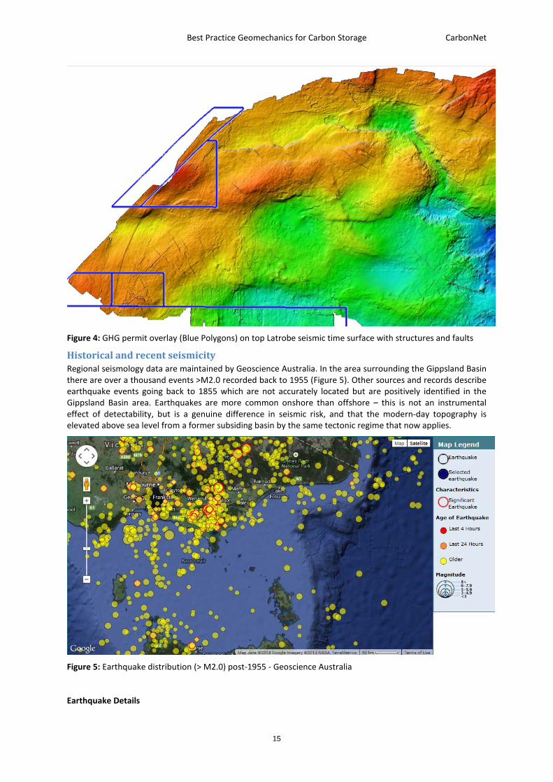
Figure 4: GHG permit overlay (Blue Polygons) on top Latrobe seismic time surface with structures and faults
Historical and recent seismicity Regional seismology data are maintained by Geoscience Australia. In the area surrounding the Gippsland Basin there are over a thousand events >M2.0 recorded back to 1955 (Figure 5). Other sources and records describe earthquake events going back to 1855 which are not accurately located but are positively identified in the Gippsland Basin area. Earthquakes are more common onshore than offshore – this is not an instrumental effect of detectability, but is a genuine difference in seismic risk, and that the modern-day topography is elevated above sea level from a former subsiding basin by the same tectonic regime that now applies.
Figure 5: Earthquake distribution (> M2.0) post-1955 - Geoscience Australia
Earthquake Details

Best Practice Geomechanics for Carbon Storage CarbonNet
16
In the area including the Gippsland Basin there are 1,700+ events of magnitude 2.0+ recorded back to 1955 including the magnitude 5.4 event at Moe on 19 June 2012. Earthquakes occur at epicentral depths of 15-20 km in the basement margins of the Gippsland Basin along old fault lines where major basin growth formerly occurred. The regional present-day stress regime is generally believed to strike-slip (SHmax~Sv>Shmin) with partitioned vertical slip along faults associated with ongoing uplift of the Strzelecki Ranges (including the Baragwanath Anticline) and mild ongoing basin inversion. With these epicentral depths, there appears to be no recognisable fault throw on shallow faults at the depth of injection and storage.
Other sources and records describe earthquake events going back to 1855 which are not accurately located but are positively identified in the broader area outside the Gippsland Basin. The largest of these was in 1892 when an M6.9 earthquake occurred in the general Tasman Sea area. This was the strongest of a series of hundreds of Tasman Sea earthquakes felt in Tasmania and Eastern Victoria which occurred between 1883 and 1892.
No earthquakes over M6.0 have been recorded onshore Victoria or in the Gippsland Basin. The largest reported event since White Settlement was in 1885 near Cape Liptrap, on the northern margin of the Bass Basin.
In 1946, an earthquake M6.2 was felt in Launceston, Tasmania – this is also reported to have originated in the Tasman Sea as with the 1883 series.
In 1982 a M6.0 earthquake was definitively located in the Tasman Sea approx. 350 km from the Gippsland coast and 200 km east of Flinders Island. The lineation between Cape Liptrap, north Flinders Island, and this area may well have been the locus of the 1883 series.
Analysis
None of the earthquakes described above have caused any reported interruptions to oil and gas production in the area. The Moe Earthquake of 19 June 2012 caused a temporary loss (generator trip from preset vibration thresholds) of 2000MW of generation primarily at the Loy Yang and Yallourn Power Stations (AEMO 2013), but one unit at Yallourn was out of action for 3 months due to minor repairs. The oil and gas fields have never had an interruption due to seismic activity, nor do they show any evidence of spill despite an evident geological history of inversion and uplift extending for millions of years beyond this historic record.
State of stress VicGCS-CarbonNet Accelerated Geoscience Exploration Program (AGEP-1) project 4 was conducted by CSIRO (Ciftci et al. 2011). This study reviewed the stress state of the basin and assessed relative reactivation and leakage risking for faults of different orientations.
An important reference paper to determine the state of stress is van Ruth et al 2006. They analyse borehole breakout and tensile crack measurements identified in earlier work by Nelson and Hillis, 2005. Van Ruth et al assess from the tensile cracks that the modern stress regime in the Gippsland Basin is on the boundary between strike-slip and reverse faulting. Shmin is close to Sv (20 and 21 MPa/km, respectively), however van Ruth et al (ibid) demonstrate in their Figures 5 and 6 that SV is clearly greater than Shmin, hence the assignment to the strike slip rather than compressional regime.
The stress state is relatively high, with SHmax of 39-40.5 MPa/km. The orientation of SHmax is NW-SE (139P
oP).
Stress data is mapped in Figure 6, courtesy of the Australasian Stress Map project at the Australian School of Petroleum.
Van Ruth et al (2006) estimate that the highest reactivation risk is for high-angle faults oriented either SSE-NNW or ENE-WSW with an estimated pore pressure limit before reactivation of optimally-located cohesionless faults of 3.78 Mpa at a depth of 2300m (i.e. 1.64 Mpa/km).

Best Practice Geomechanics for Carbon Storage CarbonNet
17
Figure 6: GHG Permits (blue polygons) overlain on Australian Stress map for the Gippsland Basin – Australian School of Petroleum
3 Injection Zone pressure history The Latrobe Formation is characterised by a strong regional artesian aquifer that connects hydraulically from onshore to offshore. Over the past few million years, meteoric water has pushed offshore to displace former saline formation waters with lower salinity water (Figure 7, Varma and Michael, 2012). This low salinity wedge has been proven by petroleum exploration wells to extend 20-40 km offshore (Kuttan et al., 1986). The low salinity wedge is the host for several oil and gas fields, many of which have been biodegraded or water-washed by the flushing effect and biological activity of the cooler, fresher waters, post oil and gas emplacement (Hoffman and Preston, 2014).

Best Practice Geomechanics for Carbon Storage CarbonNet
18
Figure 7: GHG Permits (blue polygons) overlain on salinity distribution in the Latrobe Aquifer - Varma and Michael. 2012
The original Latrobe Aquifer in the Gippsland Basin (Figure 8, Varma and Michael, 2012) has been affected by five decades of oil and gas production, and by onshore water extraction, as well as by changes in climate and rainfall. The nett effect is an observed ~1m (0.01 MPa) per annum drop in hydraulic head in the coastal area (Figure 9, Varma and Michael, 2012). The pressure decline varies spatially, being strongest in the Central Deep and Latrobe Valley, where most extraction has occurred, and weaker towards the recharge area in the Strzelecki Ranges. In the nearshore area, a former artesian head of ~50m has been reduced to hydrostatic (0m).

Best Practice Geomechanics for Carbon Storage CarbonNet
19
Figure 8: GHG Permits (blue polygons) overlain on pre-production hydraulic head in the Gippsland Basin - Varma and Michael. 2012
Figure 9: GHG Permits (blue polygons) overlain on hydraulic head change 1950-1990 - Varma and Michael. 2012
Best Practice Geomechanics for Carbon Storage CarbonNet
20
4 Development of a geomechanical model for the CarbonNet Project CarbonNet has a preliminary geomechanical model for the nearshore area and a firm Appraisal Plan to collect rock samples and conduct geomechanical tests that would lead to a rigorous pre-injection geomechanical analysis followed by more reliable injection limit designs.
Leak-off test analysis as input to the geomechanical model
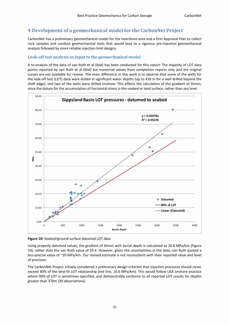
A re-analysis of the data of van Ruth et al (ibid) has been conducted for this report. The majority of LOT data points reported by van Ruth et al (ibid) are numerical values from completion reports only and the original curves are not available for review. The main difference in this work is to observe that some of the wells for the leak-off test (LOT) data were drilled in significant water depths (up to 418 m for a well drilled beyond the shelf edge), and two of the wells were drilled onshore. This affects the calculation of the gradient of Shmin, since the datum for the accumulation of horizontal stress is the seabed or land surface, rather than sea level.
Figure 10: Seabed/ground surface datumed LOT data
Using properly datumed values, the gradient of Shmin with burial depth is calculated as 20.8 MPa/km (Figure 10), rather than the van Ruth value of 19.4. However, given the uncertainties in the data, van Ruth quoted a less-precise value of ~20 MPa/km. Our revised estimate is not inconsistent with their reported value and level of precision.
The CarbonNet Project initially considered a preliminary design criterion that injection pressures should never exceed 80% of the best-fit LOT relationship (red line, 16.6 MPa/km). This would follow USA onshore practice where 90% of LOT is sometimes specified, and demonstrably conforms to all reported LOT results for depths greater than 370m (30 observations).
y = 0.02078xR² = 0.95239
0.00
10.00
20.00
30.00
40.00
50.00
60.00
70.00
80.00
90.00
0 500 1000 1500 2000 2500 3000 3500 4000
Mpa
Burial depth
Gippsland Basin LOT pressures - datumed to seabed
Datumed
80% of LOT
Linear (Datumed)

Best Practice Geomechanics for Carbon Storage CarbonNet
21
With additional detailed geomechanical work, this preliminary criterion has evolved to our proposed Best Practice Geomechanics, using the more precise and conservative Mohr-Coulomb threshold for reactivation of optimally-oriented cohesionless fractures.
Stress Polygon analysis
In order to calculate the stability of pre-existing faults, a stress polygon (Zoback et al, 2003) was constructed with stress parameters recalculated with a sea-floor datum for LOT (Shmin). The values are listed in Table 1 and compared with the values quoted by van Ruth et al for a sea-level datum.
In the stress polygon construction (Figure 11) the axes are measurements of stress gradients in MPa/km. The diagonal black line is a nominal low-stress condition where SHmax is equal to Shmin. The outer blue boundaries define the allowable maxima of Shmin and SHmax before tectonic failure will occur at the Mohr-Coulomb threshold. The point on the low-stress diagonal where vertical and horizontal lines converge is the value of Sv at 21.5 Mpa/km which is accurately known from integrated well density logs.
The offshore Gippsland region is close to the boundary between strike slip and compressional regimes. Shmin is better known than SHmax, so the offshore Gippsland Basin stress state lies on the vertical red line. SHmax is calculated from tensile fractures, following the method and observations of van Ruth et al., but recalculated with our new estimates of Shmin from datumed LOT data. This estimate of SHmax shows that offshore Gippsland (red dot) is relatively highly stressed, but is not at the Mohr-Coulomb threshold. Additional pore pressure through injection would move the local stress state closer to the threshold. The margin between the present stress condition and the Mohr-Coulomb threshold defines the allowable operating conditions for an injection project.
Table 1: Regional stress parameters and Mohr-Coulomb threshold for CarbonNet
Parameter CarbonNet Estimate CarbonNet range Van Ruth Estimate
Sv magnitude 21.5 MPa/km +0.5 MPa/km 21.0
Sh min (LOT) 20.78 MPa/km +1.0 MPa/km 20
Fault friction coefficient 0.65 +0.05 0.65
Pore pressure 9.8 MPa/km +0.5 MPa/km 9.8
Mud weight 11.2 MPa/km +0.5 MPa/km 11.2
Tensile strength 0 Up to 0.15 Mpa 0
SHmax – derived from above inputs 41.34 +1.0 MPa/km 40.5
Mohr-Coulomb Threshold 12.42 MPa/km +0.5 MPa/km 11.44 MPa/km
Mohr-Coulomb Threshold reached with additional injection pressure of:
2.62 MPa/km +0.5 MPa/km 1.64 MPa/km

Best Practice Geomechanics for Carbon Storage CarbonNet
22
Figure 11: CarbonNet stress polygon for offshore Gippsland
Van Ruth et al. calculate that the Mohr-Coulomb threshold is 11.44 Mpa/km (Table 1). The Mohr-Coulomb threshold is significantly lower than Shmin (LOT), and therefore is the stricter constraint (darker green line in Figure 13). The injection overpressure (above the original hydrostatic gradient of 9.8 MPa/km) required to reach this threshold is 1.64 MPa/km. CarbonNet assessment of the Mohr-Coulomb threshold, based on water depth corrected data, is 12.42 MPa/km - plotted as the lighter green line in Figure 13. We therefore predict a larger allowable operational overpressure value of 2.62 MPa/km (Table 1).
At the planned injection depth of 1350m, the preliminary CarbonNet geomechanical modelling predicts a safe injection limit of 16.75 MPa total pressure or 3.53 MPa above original aquifer pressure. This pressure limit should be actively managed by monitoring Bottom Hole Pressure (BHP). The pressure limit for reactivation of actual mapped faults within CarbonNet storage structures is greater than this limit, since the mapped faults are not optimally oriented with respect to regional stress (Ciftci et al., 2011).

Best Practice Geomechanics for Carbon Storage CarbonNet
23
Figure 12: Modelled pressure response after 125 Mt injection
CarbonNet dynamic modelling (Figure 12) shows that after 25 years of injection at 5 Mtpa, pore pressure rises by 16 bars (1.6 MPa) at the top of the injected interval and 11 bars (1.1 MPa) at the base of the interval (orange points in Figure 12). This pressure always remains below both the van Ruth and the CarbonNet estimates of the Mohr-Coulomb threshold. The region of appreciable pressure increase covers both the buoyant COR2R plume, which is responsible for the majority of the pressure, and also a wider region within 10-20 km of the injection point and plume extent, with a more general regional effect of < 5 bars (0.5 MPa). All of these areas are therefore fully geomechanically stable and entirely safe from Mohr-Coulomb failure.
Delta P (Bars)

Best Practice Geomechanics for Carbon Storage CarbonNet
24
Figure 13: Injection Pressure constraints for CarbonNet operations
Note that the pore pressure limit calculated above is with respect to pre-production aquifer pressures. Pressure depletion in the local area, below the original artesian gradient, is around 50 m of hydraulic head or 0.5 MPa, offering a further small buffer to injection pressure. However, CarbonNet is proceeding with Best Practice Geomechanics by assuming that the pore pressure margin is defined with respect to the modern-day aquifer pressure regime.
Allowing for the faults to have cohesion C = 5.4 Mpa, as assumed by van Ruth et al. adds an additional pressure buffer, but at this stage of project design there is no need to invoke cohesion. CarbonNet is proceeding with Best Practice Geomechanics by assuming zero cohesion.
Aquifer Pressure
For the majority of the area affected by the pressure of injection (and the buoyancy pressure resulting from accumulation of COR2R under local baffles and more regional seals), the pressures will have been partially restored towards the original artesian pressure. There will therefore be no adverse effects on nearby aquifer users such as petroleum production or onshore water abstraction.
5 CarbonNet operating conditions As discussed above, The CarbonNet Project is planned to operate at significantly less than 55% of LOT or 110% of aquifer pressure. This is 1 to 4 MPa below the Mohr-Coulomb threshold with assumed zero strength. This is in accord with Best Practice Geomechanics.
6 Proposed Operating Plan and Monitoring System Pressure will be monitored during operations by both wellhead and bottom-hole pressure and temperature measurements (plus wellhead flow meters to fully characterise the injected fluid phase conditions). Strict
0.00
5.00
10.00
15.00
20.00
25.00
30.00
35.00
40.00
0 200 400 600 800 1000 1200 1400 1600 1800 2000
Mpa
Burial depth
Gippsland Basin injection pressure limits
Datumed
80% of LOT
Fault reactivation - CarbonNet
Fault reactivation - van Ruth
CarbonNet Dynamic Model
Aquifer
Best Practice Geomechanics for Carbon Storage CarbonNet
25
bottom hole pressure constraints and operating practices will ensure that any unplanned pressure increase is immediately corrected.
A number of additional safeguards are proposed for the CarbonNet sites:
• Injection is planned in a deeper aquifer than final storage. Multiple topseals separate the injection zone from the overburden and offer a guarantee of multiple pressure-isolating seals.
• Multiple seals and a large vertical distance (1.5 km) separate the injection zone from the substrate, hence offering effective isolation from known and unknown basement features.
• Injection is planned to be well away (1 km or more) from any mapped faults within the injection zone, even if these are shown to be entirely inactive and stabilised – this is an additional element of Best Practice Geomechanics.
• Because of the tortuous path and substantial buffer volume between the injection zone and the effective topseal for COR2R, a significant proportion of the injected COR2R will be delayed or permanently captured before the main topseal encountered. This results in a reduced pressure and volume at the main topseal, and hence a lower stress operating environment. This again accords with Best Practice Geomechanics.
7 Temperature and other effects of injection The planned injection temperature for COR2R will be close to, but a little cooler than the formation temperature. There will thus be a slight degree of thermal contraction. Equivalent studies at other injection sites such as the CO2CRC Otway project (LaForce et al., 2014) demonstrate that there is no likelihood of any thermal-triggered events during normal operation.
Geochemical reactivity with the host rocks may partially dissolve some rock-forming minerals and cements, and secondary minerals and cements may precipitate. These changes will have effects on rock strength and may generate minor secondary pressure effects due to changes of volume with change of phase. The Latrobe group consists of quartz-dominated clastic sediments with relatively minor feldspar and lithics. Cements are generally also quartzose (rather than carbonate). Therefore, the majority of the rock matrix is highly resistant to geochemical alteration and only minor rock constituents will be altered (Schacht 2008a, b).
8 Manage pressure effectively and continuously Pressure will be monitored during operations by both wellhead and bottom-hole pressure and temperature measurements (plus wellhead flow meters to fully characterise the injected fluid phase conditions). Strict bottom hole pressure constraints and operating practices will ensure that any unplanned pressure increase is immediately corrected.
9 Monitor for possible microseismicity and respond proactively Because the CarbonNet project will be operating to Best Practice Geomechanics – below the Mohr-Coulomb threshold, it is highly unlikely that there will be any detectable micro seismic events during or after project operation. However, to demonstrate this in practice requires active monitoring and comparison to a baseline of activity before injection.
A research programme funded by ANLEC and the Commonwealth government - the GipNet project -is planning to deploy local high-precision seismometers to provide local coverage of small events, especially in the nearshore region of interest (CarbonNet 2016a).
Worldwide studies show that seismicity can occur where fluid is added to or removed from the crust in significant quantities (e.g. Nicol et al., 2011, Ellsworth, 2013). To a first approximation, the degree of seismicity is proportional to the pressure increase during production/injection. In the Gippsland Basin, despite large volumes of fluid abstraction from the Latrobe aquifer, there is no evidence of any geomechanical instability.
The Gippsland Basin has a number of characteristics that make it highly attractive for CCS. These include the excellent reservoir quality and thickness, the world-class aquifer support, and the existence of multiple seals proven by extensive petroleum industry data.
However, the basin is also in a relatively high stress state. Compared to the study of Konstantinovskaya et al. 2012, only a moderate pressure increase would be required to cross the Mohr-Coulomb threshold and

Best Practice Geomechanics for Carbon Storage CarbonNet
26
reactivate pre-existing fractures. In other basins with relatively poor reservoirs and/or aquifers, this could give rise to a geomechanical warning flag, but because of the excellent reservoir injectivity and the extensive and excellent aquifer, CarbonNet will not experience pressure problems.
Fifty years of operating data from the petroleum industry has very accurately defined the aquifer response to fluid volume changes. Detailed dynamic reservoir modelling shows that the CarbonNet Project will operate at all times comfortably within all estimates of the Mohr-Coulomb threshold.
The injection and storage reservoirs are also only lightly cemented and are therefore geomechanically weak and hence safe - this means that even if there were reactivation of a fracture, the energy release would be minimal or imperceptible.
Implications for injection at the CarbonNet sites
Data Availability: CarbonNet operates in a well-characterised basin with ample data to establish parameters.
Site Characterisation: Regional and site characterisation work has established a credible geomechanical context for planned future injection operations. The Gippsland Basin has an excellent, pressure-dissipating, basinwide aquifer.
Operating Practice: CarbonNet injection is planned to follow Geomechanical Best Practice by operating below the Mohr-Coulomb threshold. CarbonNet dynamic model simulations show that maximum predicted overpressure which is reached at the end of injection (by a combination of buoyancy and injection pressure) will be comfortably less than any estimate of the Mohr-Coulomb threshold.
Continuous bottom-hole pressure monitoring and strict feedback protocols referenced to the geomechanical model will ensure that any unwanted pressure increase is immediately corrected. Local microseismic monitoring will inform on any changes to background rates and magnitudes of microseismicity and allow proactive changes to injection zones and rates, if required.
Summary and conclusions As illustrated by the approach taken by the CarbonNet Project, it is important for CCS projects to understand and follow Best Practice Geomechanics. In summary CCS proponents should seek or implement:
• Data-rich brownfield basins that are well-characterised by extensive good-quality data. • The data must be available to the CCS proponent through a data access regime, or the proponent
must have access by other means to the data – which will generally restrict Best Practice CCS activity to the petroleum industry and to State organisations.
• Avoidance of resource conflict with existing or possible future petroleum activity, however this obligation can be offset by synergistic benefits of future sharing of data, logistics, and infrastructure.
• Additional data types that are not routinely collected by the petroleum industry. Therefore, even in a data-rich basin, additional targeted data acquisition might be needed.
• An excellent reservoir with good injectivity, and good aquifer support. This will reduce the pressure build-up during injection and avoid and pressure problems.
• As an additional safeguard, weak rocks are preferred to strong rocks and low-stress basins to high-stress basins. Even if a fracture were activated, there is limited stored energy in weak rocks and low-stress basins and therefore low levels of energy release.
• Continuous monitoring of both reservoir pressure and geological stress state are required during and after injection to demonstrate concordance with modelled pressure behaviour and geomechanical stability.

Best Practice Geomechanics for Carbon Storage CarbonNet
27
• A well-designed warning and response system for geomechanical issues in the subsurface. A clearly-defined, predictive (not reactive) and timely set of actions is required in response to new subsurface information.
We conclude with our summary of principles for Best Practice Geomechanics:
Data Availability
1. Operate in a well-characterised basin with openly available data Site Characterisation
2. Develop good local characterisation including additional data types 3. Choose the injection zone informed by local context 4. Ensure that a sound and verified geomechanical model is available
Operating Practice
5. Operate below the Mohr-Coulomb failure criterion 6. Have a clear operational plan and monitoring system 7. Consider other fracture mechanisms/defects 8. Manage pressure effectively and continuously 9. Monitor for possible microseismicity and respond proactively

Best Practice Geomechanics for Carbon Storage CarbonNet
28
References AEMO 2013 Multiple Contingency Event Following an Earthquake in Victoria on 19 June 2012 32TUhttps://www.aemo.com.au/-/media/Files/Electricity/NEM/Market_Notices_and_Events/Power_System_Incident_Reports/2012/Victoria_Earthquake_19_June_2012_v3.pdf accessed 27 Mar 2017U32T
Bachu, A., Hawkes, C., Lawton, D., Pooladi-Darvish, M., Perkins, E., 2008 - CCS site characterisation criteria IEAGHG 32TUhttp://www.globalccsinstitute.com/publications/ccs-site-characterisation-criteria U32T accessed online 27 Mar 2017
Benson, S., M. and 35 others, 2004 - GEO-SEQ Best Practices Manual. Geologic Carbon Dioxide Sequestration: Site Evaluation to Implementation. 32TUhttp://escholarship.org/uc/item/27k6d70j U32T accessed 27 Mar 2017
CarbonNet 2015a - Site characterisation for carbon storage in the near shore Gippsland Basin. GLOBAL CCS INSTITUTE https://www.globalccsinstitute.com/publications/carbonnet-project-site-characterisation-carbon-storage-near-shore-gippsland-basinaccessed 23 Jan 2017
CarbonNet 2015b - 3D mapping and correlation of intraformational seals within the Latrobe Group in the nearshore Gippsland Basin GLOBAL CCS INSTITUTE https://www.globalccsinstitute.com/publications/carbonnet-project-3d-mapping-and-correlation-intraformational-seals-within-latrobe-group-nearshore-gippsland-basin accessed 23 Jan 2017
CarbonNet 2015c - Integrity of wells in the near-shore area Gippsland Basin Victoria GLOBAL CCS INSTITUTE https://www.globalccsinstitute.com/publications/carbonnet-project-integrity-wells-near-shore-area-gippsland-basin-victoria accessed 23 Jan 2017
CarbonNet 2015d - CarbonNet storage site selection & certification: challenges and successes GLOBAL CCS INSTITUTE https://www.globalccsinstitute.com/publications/carbonnet-storage-site-selection-and-certification-challenges-and-successes accessed 23 Jan 2017
CarbonNet 2016a - GipNet – Baseline environmental data gathering and measurement technology validation for nearshore marine Carbon Storage GLOBAL CCS INSTITUTE https://www.globalccsinstitute.com/publications/gipnet-%E2%80%93-baseline-environmental-data-gathering-and-measurement-technology-validation-nearshore-marine-carbon-storage accessed 23 Jan 2017
CarbonNet 2016b - Probabilistic approach to CO2 plume mapping for prospective storage sites: The CarbonNet experience GLOBAL CCS INSTITUTE http://hub.globalccsinstitute.com/sites/default/files/publications/201298/ 32TUhttps://www.globalccsinstitute.com/publications/probabilistic-approach-CO2-plume-mapping-prospective-storage-sites-carbonnet-experience accessed 23 Jan 2017U32T
Cesca, S., Grigoli, F., Heimann, , S., González, A., Buforn, E., Maghsoudi, S., Blanch, E., and Dahmn, T. (2014) - The 2013 September–October seismic sequence offshore Spain: a case of seismicity triggered by gas injection? Geophysical journal international 198 (2), 941-953
Chadwick, A., Arts, R., Bernstone, C., May, F., Thibeau, S., Zweigel, P., 2008 - Best Practice for the CO2 Storage in Saline Aquifers – Observations and Guidelines from the SACS and CO2STORE Projects. British Geological Survey, Nottingham, UK.
Chiamonte, L., 2008 Geomechanical Characterisation and reservoir simulation of a CO2 sequestration project in a mature oil field, Teapot Dome, Wy. Ph.D. Dissertation, Stanford University
Chiaramonte, L., Zoback, M.D., Friedmann, J., Stamp, V., 2008 - Seal integrity and feasibility of CO2 sequestration in the Teapot Dome EOR pilot: geomechanical site characterisation. Env. Geol. 54(8), 1667-1675.
Ciftci, B. Bn., Langhi, L, Strand, J., and Giger, S. B., 2011 - Fault Seal Evaluation of the Near-shore/Onshore Gippsland Basin. CSIRO Report No. EP115664
Deloitte, 2015 – A need unsatisfied: Blueprint for enabling investment in CO2 storage. Report for the UK Crown Estate, February 2016.
Ellsworth, W. L., 2013 - Injection-Induced Earthquakes. Science 12 July 2013: Vol. 341 no. 6142

Best Practice Geomechanics for Carbon Storage CarbonNet
29
Gibson-Poole, C.M., Svendsen, L., Underschultz, J., Watson, M.N., Ennis-King, J., van Ruth, P.J., Nelson, E.J., Daniel, R.F., and Cinar, Y., 2006 - Gippsland Basin geosequestration: A potential solution for the Latrobe Valley brown coal CO2 emissions. APPEA Journal, 2006; 46(1):413-433
Grasso, J.R. (1992). Mechanics of seismic instabilities induced by the recovery of hydrocarbon. Pure Appl. Geophys. 139(3/4), 507–533.
Hoffman, N., and Preston, J., 2014 - Geochemical interpretation of partially filled hydrocarbon traps in the nearshore Gippsland Basin. APPEA Journal 2014 (in press)
IEAGHG 2009 CCS site characterisation criteria 32TUhttp://www.globalccsinstitute.com/publications/ccs-site-characterisation-criteria U32T accessed online 27 Mar 2017
IPCC (Intergovernmental Panel on Climate Change), 2005. Chapter 5: Underground geological storage. In: Special Report on Carbon Dioxide Capture and Storage. Cambridge University Press, Cambridge, U.K., and New York, NY, U.S.A.
Juanes, R., Hager, B.H., and Herzog, J.H. 2012 - No geologic evidence that seismicity causes fault leakage that would render large-scale carbon capture and storage unsuccessful. Proc Natl Acad Sci USA 109(52):E3623
Keetley, J.T, Nourollah, M.H, Tait, A.M., Hoffman, N, Hall, M., & Asquith, K., 2010 - High Resolution Structural Seismic Stratigraphic Analysis of the Onshore & Offshore Gippsland Basin, Victoria, Australia, VicGCS 3D Geologic Framework of the Gippsland Basin, (in review) 298pp
Konstantinovskaya, E., Malo, M., and Castillo, D.A.. 2012 - Present-day stress analysis of the St. Lawrence Lowlands sedimentary basin (Canada) and implications for caprock integrity during CO2 injection operations. Tectonophysics 518–521 (2012) 119–137
Kuttan, K., Kulla, J.B. And Newman, R.G., 1986—Freshwater influx in the Gippsland Basin: impact on formation evaluation, hydrocarbon volumes and hydrocarbon migration. APPEA Journal, 26 (1), 242–249.
LaForce, T., Mijić, A., Ennis-King, J. and Paterson, L.: Analytical solutions for nonisothermal injection including heat loss from the reservoir, part 2: Pressure and stress, Advances in Water Resources, (2014b), 10.1016/j.advwatres.2014.08.008
Lee, D.W., Mohamed, F., Will, R., Bauer, R., and Shelander, D., 2014 - Integrating Mechanical Earth Models, Surface Seismic, and Microseismic Field Observations at the Illinois Basin - Decatur Project. Energy Procedia 63 ( 2014 ) 3347 – 3356
Loizzo, L, Lecampion, B., & Mogilevskaya, S., 2016 - The role of geological barriers in achieving robust well integrity. GHGT-13 Abstract
Lucier, A., Zoback, M., 2008 - Assessing the economic feasibility of regional deep saline aquifer CO2 injection and storage: A geomechanics-based workflow applied to the Rose Run sandstone in eastern Ohio, USA. Int. J. Greenhouse Gas Control, 2(2), 248-258.
Nelson, E.J., and Hillis, R.R., 2005 - In Situ stresses of the West Tuna area, Gippsland Basin: Australian Journal of Earth Sciences, 52, 299–313.
Nicol, A., R. Carne, R., M. Gerstenberger, M., and Christophersen, A. 2011 - Induced seismicity and its implications for CO2 storage risk. Proceedings of 10 P
thP International Conference on Greenhouse Gas Control
technologies. Energy Procedia Volume 4, 2011, Pages 3699–3706
Oxburgh, R, 2016 – Lowest cost decarbonisation for the UK: The critical role of CCS. Report of the Parliamentary Advisory Group on CCS, September 2016.
Power, M.R., Hill, K.C., Hoffman, N., Bernecker, T., Norvick, M., 200 -, The structural and tectonic evolution of the Gippsland Basin, results from 2D section balancing and 3D structural modelling., Hill, K.C. and Bernecker, T.(Eds.), Eastern Australasian Basins Symposium, A refocussed energy perspective for the future, Petroleum Exploration Society of Australia, Special Publication, 373-390
Rinaldi, P.R, Rutqvist, J, Finsterle, S., Liu, H.H., 2014 - Forward and inverse modeling of ground surface uplift at In Salah, Algeria https://www.researchgate.net/publication/262875508 accessed online 28 Mar 2017

Best Practice Geomechanics for Carbon Storage CarbonNet
30
Ringrose, P.S., Mathieson, A.S., Wright, I.W., Selama, F., Hansen, O., Bissell, R., Saoula, N., and Midgely, J. 2013 - The In Salah CO2 storage project: lessons learned and knowledge transfer. Energy Procedia 37 ( 2013 ) 6226– 6236
Rutqvist, J., 2012 - The Geomechanics of CO2 Storage in Deep Sedimentary Formations. Geotech Geol Eng (2012) 30:525–551
Schacht, U., 2008a – Latrobe Group sandstones in Tuna Field, Gippsland Basin – Petrology and Diagenesis. CO2CRC Report RPT08-0989
Schacht, U., 2008b – Latrobe Group sandstones in Tuna Field, Gippsland Basin – Petrology and CO2-related Diagenesis. CO2CRC Report RPT08-0990
Sminchak, J.R. and N. Gupta. 2001 - Issues Related to Seismic Activity Induced by the Injection of CO2 in Deep Saline Aquifers. First National Conference on Carbon Sequestration, Wash., DC, May 14-17, 2001.
TNO (2014) Literature review on Injection-Related Induced Seismicity and its relevance to Nitrogen Injection. TNO 2014 R11761 32TUhttp://nlog.nl/resources/Seismic_Risk/TNO-Report-2014-R11761-Public-final18122014_anonymous.pdfU32T Accessed online 17 Mar 2017
Torsaeter, M., Todorovic, J., Lavrov, A., Gawel, K., Lund, H., Roy. P., & S. Carroll, S., 2016 - Avoiding damage of CO2 injection wells caused by temperature variations GHGT-13 Abstract
van Ruth, P. J., Nelson, E. J., and Hillis, R.R., 2007 - Fault reactivation potential during CO2 injection in the Gippsland Basin, Australia: Exploration Geophysics 37, 50-59
Varma, S., and Michael, K., 2012 - Impact of multi-purpose aquifer utilisation on a variable-density groundwater flow system in the Gippsland Basin, Australia. Hydrogeology Journal (2012) 20:119-134
Verdon JP, Kendall J, Stork AL, Chadwick R, White D, Bissell RC 2013 - Comparison of geomechanical deformation induced by megatonne-scale CO2 storage at Sleipner, Weyburn, and In Salah 32TUwww.pnas.org/content/110/30/E2762.full.pdfU32T Accessed online 28 Mar 2017
Verdon JP, Kendall JM, White DJ, Angus DA 2011 - Linking microseismic event observations with geomechanical models to minimize the risks of storing CO2 in geological formations. Earth Planet Sci Lett 305:143–152
Vilarrasa V, Carrera J 2015 - Geologic carbon storage is unlikely to trigger large earthquakes and reactivate faults through which CO2 could leak. Proc Natl Acad Sci USA 112 (19):5938–5943.
Weingarten, M., Ge, S., Godt, J.W., Bekins, B.A., and Rubinstein, J.L. 2015 - High-rate injection is associated with the increase in U.S. mid-continent seismicity. Science 348, 1336–1340.
White, J. A., and Foxall, W., 2016 - Assessing induced seismicity risk at CO2storage projects: Recent progress and remaining challenges. IJGGC 49, 413-424
Zep 2014 - Business models for commercial CO2 Transport, and Storage. Zero Emissions Platform report to the European Commission.
Zhou, Q., Birkholzer, J.T., C.F. Tsang, Rutquist, J. 2008 - A method for quick assessment of CO2 storage capacity in closed and semi-closed saline formations. Int. J. Greenhouse Gas Control, 2(4), 626-639.
Zoback M.D. and Gorelick S.M, 2012a - Earthquake triggering and large-scale geologic storage of carbon dioxide. Proc Natl Acad Sci USA 109 (26):10164–10168.
Zoback M.D. and Gorelick S.M, 2012b - No geologic evidence that seismicity causes fault leakage that would render large-scale carbon capture and storage unsuccessful. Proc. Natl. Acad. Sci. USA 2012 109 (52) E3623
Zoback M.D. and Gorelick S.M. 2015 - To prevent earthquake triggering, pressure changes due to CO2 injection need to be limited. Proc Natl Acad Sci USA 112 (33):E4510.
Zoback, M.D., Barton, C.A., Brudy, M., Castillo, D.A., Finkbeiner, T., Grollimund, B.R., Moos, D.B., Peska, P., Ward, C.D. & Wiprut, D.J. 2003 - Determination of stress orientation and magnitude in deep wells. - Int. J. Rock Mech. Min. Sci., 40 (7-8), 1049-1076.
Zoback, M.D. 2007 - Reservoir Geomechanics. Cambridge University Press, New York.

Best Practice Geomechanics for Carbon Storage CarbonNet
31