Embed Size (px)
Citation preview

REV. 00 - Mar. 07
TECHNICAL SERVICE MANUAL
PRIMEA LINE2007
Issue March 2007
All parts of this document are property of Saeco International Group. All rights reserved. This document and relative information herein is provided without liability deriving from any errors or omissions. Furthermore, no part may be reproduced, used or collected with the exception of that authorized in writing or in accordance with a contrac-tual clause.
REV. 00 - Mar. 07
PRIMEA 2007 Contents
1/1
PRIMEA TECHNICAL SERVICE MANUAL (rev.00 March 07)
1. Introduction (rev.00) 1.1 Documentation required 1.2 Tools and equipment required 1.3 Safety warnings
2. Technical data (rev.00) 2.1 Product technical data 2.2 Internal / external machine components
3. Summarized instructions (rev.00) 3.1 Client and programming menu (rev.00) 3.2 Maintenance and cleaning (rev.00)
4. Diagrams (rev.00) 4.1 Wiring diagram (rev.00) 4.2 Component load table (rev.00) 4.3 Water circuit diagram (rev.00)
5. Troubleshooting (rev.00) 5.1 Primea Touch and Touch Plus test functions (rev.00) 5.2 Primea Touch e Touch Plus diagnosis function (rev.00)5.3 Primea Ring test functions (rev.00) 5.4 Primea Ring diagnosis function (rev.00) 5.5 Error messages for Service personnel (rev.00) 5.6 Problems, Causes, Remedies (rev.00)
6. Operating logic (rev.00) 6.1 Multi-way valve (rev.00) 6.2 Autocappuccino assembly (rev.00) 6.3 Motor-driven tray (rev.00) 6.4 Prima water (rev.00) 6.5 SBS valve (rev.00)
7. Component assembly / disassembly (rev.00) 7.1 Top cover (rev.00) 7.2 Right side cover (rev.00) 7.3 Left side cover (rev.00) 7.4 Coffee dispensing head (rev.00) 7.5 Electronics (rev.00) 7.6 Gearmotor (rev.00) 7.7 Pump (rev.00) 7.8 Boiler and multi-way valve assembly (rev.00) 7.9 Boiler (rev.00) 7.10 Multi-way valve (rev.00) 7.11 Oetiker clamp assembly and disassembly (rev.00) 7.12 Grinder (rev.00) 7.13 Grinder adjustment/assembly and disassembly 7.14 Strength adjustment (rev.00) 7.15 Autocappuccino facility (rev.00) 7.16 Motor-driven drip tray (rev.00)
8. Maintenance schedule (rev.00) 8.1 Routine maintenance Check list (rev.00)
9. Amendments made to technical service manual (rev.00) 9.1 Latest amendments (rev.00)
REV. 00 - Mar. 07
CHAPTER 1 INTRODUCTION
REV.00 PRIMEA 2007 Chapter 01

REV. 00 - Mar. 07
1.1 Documentation required
The following technical documentation l is required for repairs:
Instruction booklet for specific model Technical documentation for specific model (diagrams, exploded drawings)
1.2 Tools and equipment required
As well as the standard equipment, the tools listed below are required.
1 Special screwdriver with Torx T15 tip and Pozi Drive screwdriver for casing and work on the grinder.
1 digital thermometer with full 200°C scale This must be suitable for measuring in liquids and on surfaces. 1 set of pliers for Oetiker clamps
1 pincer
1.3 Safety warning
Before starting operations on the machine, consult the instruction booklet. Observe all current standards related to the repair of domestic appliances.
Always disconnect the power plug from the mains before carrying out repairs. Simply turning off the main switch is not sufficient to prevent electrical discharge.
This domestic appliance is rated as insulation class I. Insulation and dielectric rigidity tests must be performed on completion of repairs.
1/1 PRIMEA 2007 Chapter 01
REV. 00 - Mar. 07
CHAPTER 2 TECHNICAL DATA
REV.00 PRIMEA 2007 Chapter 02

REV. 00 - Mar. 07
2.1 Product and component technical data
Power supply and output: 230V~, 50 Hz, 1500 W / 120V~,50/60 Hz, 1300WTemperature control: 2 (NTC) variable resistor sensors – transmit the value to
the electronic boardSafety system: Thermostat at 190°C with manual reset on
both boilers + 192° fuseCoffee heat exchanger output:Stainless steel
Steam heat exchanger outputStainless steel
1300 W - to dispense coffee and hot water
1090 W – for steam delivery
Motor-driven tray 24V stepper motorWater levelsensor Capacitive sensorGearmotor: DC motor (24 V) in two directions
of rotationCup warmer plate: Activated via MENU display
PTC TypePump: Ulka reciprocating piston type with thermal cutout at
100°C 48 W, 230V, 50 Hz, Type EP5 GW41 W, 120V, 50 Hzapprox. 13 - 15 bars
Pressure relief valve: Opening at approx. 17 - 19 barsWater filter: In tank Grinder: DC motor with ceramic plate
grinders Coffee strength control Hall sensor – Pulse control. Dose adjustment can
be set from 7 – 10g.Multi-function valve Beverage selection controlCappuccino valve Enables automatic frothingAmps: During heating phase
approx. 5.6A to 230V / 10.8A to 120VEnergy consumption: On Stand –By approx. 4.6 Wh in machine ready status no
beverages dispenses 39Wh 4.5A (230V)Dimensions: l x h x d in mm: 350/390/430Weight: 14 kgWater tank holds: 1.75 l / 0.46 Gal Coffee container capacity 350 g. coffee beansMilkcontainer capacity 0.32 l / 10.8 ozHeat exchanger capacity: approx. 10 cc / 0.34 ozWater circuit filling time: approx. 10 sec on first filling cycleHeating time: approx. 55 sec.Dispensed drink temperature: approx. 73°C - 83°CGrinding time: approx. 6-8 sec.
1/3PRIMEA 2007 Chapter 02

REV. 00 - Mar. 07
Grounds drawer
Service door
Main on/offswitch
Pre-groundcoffee shoot
Coffee bean hopper lidCoffee bean
coffee beans
Cup warmer
Touchscreen display
SBS
Dispensing head
Drip tray
Touch sensor to raise/lowerdrip tray
Milk tank com-partment
Water tank
Hot water dispense pipe (spout)
Dispensing head Drip tray
2.2 Internal / external machine components
2/3
External:
PRIMEA 2007 Chapter 02

REV. 00 - Mar. 07
Internal:
Brew drive assembly compartment
Multi-way valveBoiler valve assembly
Cappuccino valve assembly
Grinder
Door microswitch
Cappuccino valve assembly
Power board
PRIMEA 2007 Chapter 023/3

REV. 00 - Mar. 07
CHAPTER 3 BRIEF
INSTRUCTIONS
REV.00 PRIMEA 2007 Chapter 03

REV. 00 - Mar. 07
3.1 Client and programming menu
Client menu: To access, press “Programming menu”
Machine settings: Modify main machine parameters
Beverage settings
Coffee preparation
menu
Main menu
Machine settings
Set clockMain-tenance
Standby
The programming menu will open:
Machine function programming
Maintenance (appliance cleaning)
Detailed beverage programming
- Current date and time- Standby timer- Set on/off times
during the day
Specials Additional functions
Special functions
Set appliance to standby
Extra functions
Go back to main menu
Waterfilter
Machinesettings
Language
Rinsetones and
buzzerwarnings
Cup illumination on/off
Set menu language
Set/enable buzzers
Set machine operation for use with a “Prima water” filter
Set circuit rinsing
Display Water hardness
Set display colour brightness Set water
hardness
Cupillumination
Cup warmer function
To set cup warmer function Go back Go back to menu
Restore default settings
1/5
Submenu
PRIMEA 2007 Chapter 03

REV. 00 - Mar. 07
Maintenance: Maintenance and appliance cleaning
Coffee circuit
cleaning
Go back to menu
Maintenance
Displaylock
De-scaling
Milk circuit cleaning cycle
Go back
From this menu you can:
Lock the touchscreen
Start milk circuit cleaning cycle
Start the dispensing head cleaning cycle
Run descaling cycle
Special function: Reset factory settings
Go back to menu
Specials
Factory settings
Go back
2/5
Reset factory settings
Beverage settings: Programming individual beverages
Espresso
Caffè
Caffè lungo
Espressomacchiato
latte macchiato
Cappuccino
Goback
Go backto menu
Beverage settings
Normal pre-brewing
Hottemperature
Ground coffee strengthMedium
Goback
Go back to menu
Coffee settings
Restore defaultsettings
The temperature of the dispensed coffee
Amount of coffee to grind
PRIMEA 2007 Chapter 03

REV. 00 - Mar. 07
Timer settings:
Set clock
Go back to menu
Clock settings
Clock settings
Stand-by settings
Go back
Set date and display format
Set current time
Demo
Additional functions
Caffè in the world
Beverage counters
Go back Go back to menu
Restore defaultsettings
Savesettings
Additional functions:
3/5PRIMEA 2007 Chapter 03
To set stand-by parameters after coffee has been dispensed
Coffee type selection
Total beverages dispensed
Presentation of appliance

REV. 00 - Mar. 07
3.2 Maintenance and cleaning
4/5PRIMEA 2007 Chapter 03
STEPSA Empty coffee grounds drawer As instructedB Empty drip tray As necessaryC Clean water tank WeeklyD Clean the coffee bean hopper As necessaryE Clean casing As necessaryF Clean and grease the dispensing head Once a month or every
500 coffees dispensedG Clean brew group filters Once a monthH Descaling As instructedI Clean milk circuit After each time milk dispensedJ Clean drip tray WeeklyK Clean coffee circuit Weekly
Descaling
Hardness Water hardness Descaling frequency
Descaling frequencywhen usingAqua Prima
1 Soft water (up to 7ºdH) Approx. every 3 months/120 l (31.6 Gal)
Approx. every 3 months/ 150 l (39.5 Gal)
2 Medium water (7º-14ºdH) Approx. every 2 months / 90 l (23.75 Gal)
Approx. every 2 months/ 120 l (31.6 Gal)
3 Hard water (15º-21ºdH) Approx. every 6 weeks/ 60 l (15.8 Gal)
Approx. every 6 weeks/ 90 l (23.75 Gal)
4 Very hard water (over 21ºdH) Approx. every 4 weeks/ 30 l (7.9 Gal)
Approx. every 4 weeks/ 60 l (15.8 Gal)
DESCALINGHard-ness Water hardness Descaling
frequency Descaling frequency
when usingAqua Prima1 Soft water (up to 7ºdH) Approx. every 3
months/120 l (31.6 Gal) Approx. every 3 months/ 240 l (63.2 Gal)
2 Medium water (7º-14ºdH) Approx. every 2 months/ 90 l (23.75 Gal)
Approx. every 2 months/ 180 l (47.4 Gal)
3 Hard water (15º-21ºdH) Approx. every 6 weeks/ 60 l (15.8 Gal)
Approx. every 6 weeks/ 120 l (31.6 Gal)
4 Very hard water (over 21ºdH) Approx. every 4 weeks/ 30 l (7.9 Gal)
Approx. every 4 weeks/ 60 l (15.8 Gal)
Descaling for Primea Duo - Touch Plus and Touch
Descaling for Primea Ring

REV. 00 - Mar. 07
5/5PRIMEA Chapter 03
Mod
elFu
nct
ion
Scre
en m
essa
ges
Pos
sibl
e va
riat
ion
sM
ode
Du
rati
onP
ossi
bilit
y to
sto
p/ch
ange
Pri
mea
C
appu
ccin
o To
uch
Plu
sM
ilkTh
e ap
plia
nce
requ
ests
tha
t th
e m
ilk c
ircui
t is
pu
lse-
rin
sed
right
aw
ay;
beve
rage
s ca
n st
ill b
e se
lect
ed.
Pr
ess
key
or s
elec
t fr
om m
enu
Appr
ox. 3
0 Se
cN
o
Aft
er 2
0 m
inu
tes
If d
epar
tmen
t is
not
rin
sed,
bev
erag
es c
an n
o lo
nger
be
sele
cted
.Th
is r
efer
s to
milk
-bas
ed b
ever
ages
onl
y.
Pres
s ke
y or
sel
ect
from
men
uAp
prox
. 30
Sec
No
Afte
r 1
4 d
ays,
the
app
lianc
e re
ques
ts t
hat
is c
lean
ed w
ith w
ith
a c
lean
ing
tabl
et
or p
owde
r.
Pres
s ke
y or
sel
ect
from
men
uAp
prox
. 10
Min
Dur
ing
diag
nosi
s
If it
is n
ot c
lean
ed w
ithin
21
day
s, a
ll be
vera
ges
will
be
bloc
ked.
Pres
s ke
y or
sel
ect
from
men
uAp
prox
. 10
Min
Dur
ing
diag
nosi
s
fr
equ
ency
From
whe
n th
e de
scal
ing
mes
sage
app
ears
, the
app
lian
ce c
oun
ts d
own
inte
rnal
ly
from
20
0 c
offe
es. A
fter
10
0 c
offe
es, t
he
cou
ntd
own
app
ears
on
th
e di
spla
y,
then
for
the
last
30
cof
fees
, it
flas
hes
(20
0 be
vera
ges
of a
ny t
ype
and
size
in m
l ar
e co
unte
d).
The
coun
tdow
n fo
r th
e w
hole
200
co
ffee
s is
sho
wn
on t
he d
ispl
ay.
Ap
prox
. 45
Min
Dur
ing
diag
nosi
s
Pri
mea
C
appu
ccin
o To
uch
M
ilkTh
e ap
plia
nce
requ
ests
tha
t th
e m
ilk c
ircui
t is
pu
lse-
rin
sed
right
aw
ay;
beve
rage
s ca
n st
ill b
e se
lect
ed.
Pr
ess
key
or s
elec
t fr
om m
enu
Appr
ox. 3
0 Se
cN
o
Aft
er 2
0 m
inu
tes
If d
epar
tmen
t is
not
rin
sed,
bev
erag
es c
an n
o lo
nger
be
sele
cted
.Th
is r
efer
s to
milk
-bas
ed b
ever
ages
onl
y.Pr
ess
key
or s
elec
t fr
om m
enu
Appr
ox. 3
0 Se
cN
o
Afte
r 1
4 d
ays,
the
app
lianc
e re
ques
ts t
hat
is c
lean
ed w
ith w
ith a
cle
anin
g ta
blet
or
pow
der.
Pr
ess
key
or s
elec
t fr
om m
enu
Appr
ox. 2
5 M
inD
urin
g di
agno
sis
If it
is n
ot c
lean
ed w
ithin
21
day
s, a
ll be
vera
ges
will
be
bloc
ked.
Pres
s ke
y or
sel
ect
from
men
uAp
prox
. 25
Min
Dur
ing
diag
nosi
s
fr
equ
ency
From
whe
n th
e de
scal
ing
mes
sage
app
ears
, the
app
lian
ce c
oun
ts d
own
inte
rnal
ly
from
20
0 c
offe
es. A
fter
10
0, t
he
cou
ntd
own
app
ears
on
th
e di
spla
y th
en f
or
the
last
30
cof
fees
, th
e m
essa
ge fl
ash
es o
n t
he
scre
en (
200
beve
rage
s of
any
ty
pe a
nd s
ize
in m
l are
cou
nted
).
The
coun
tdow
n fo
r th
e w
hole
200
co
ffee
s is
sho
wn
on t
he d
ispl
ay.
Ap
prox
. 45
Min
Dur
ing
diag
nosi
s
Pri
mea
C
appu
ccin
o R
ing
Milk
The
appl
ianc
e re
ques
ts t
hat
the
milk
circ
uit
is p
uls
e-ri
nse
d rig
ht a
way
; be
vera
ges
can
still
be
sele
cted
.
Pres
s ke
y or
sel
ect
from
men
uAp
prox
. 30
Sec
No
Aft
er 2
0 m
inu
tes
If it
is n
ot r
inse
d, m
ilk-b
ased
bev
erag
es c
an n
o lo
nger
be
sele
cted
.
Pres
s ke
y or
sel
ect
from
men
uAp
prox
. 30
Sec
No
Afte
r 7
day
s, t
he a
pplia
nce
requ
ests
tha
t is
cle
aned
with
with
a c
lean
ing
tabl
et/
pow
der.
From
V. S
W. 0
1.0
0.0
7: A
fter
14
days
, th
e ap
plia
nce
requ
ests
tha
t is
cle
aned
w
ith w
ith a
cle
anin
g ta
blet
or
pow
der.
Pres
s ke
y or
sel
ect
from
men
uAp
prox
. 25
Min
Dur
ing
diag
nosi
s, y
ou c
an
vary
not
ifica
tion
and
bloc
k tim
es, a
nd d
urin
g te
stin
g yo
u ca
n re
set
Lev.
. B m
ode.
If it
is n
ot c
lean
ed w
ithin
14
day
s, a
ll be
vera
ges
will
be
bloc
ked,
From
V. S
W. 0
1.0
0.0
7: I
f it
is n
ot
clea
ned
with
in 2
1 da
ys, a
ll be
vera
ges
will
be
bloc
ked.
Pr
ess
key
or s
elec
t fr
om m
enu
Appr
ox. 2
5 M
in
Dur
ing
diag
nosi
s, y
ou c
an
vary
not
ifica
tion
and
bloc
k tim
es, a
nd d
urin
g te
stin
g yo
u ca
n re
set
Lev.
B
fr
equ
ency
From
whe
n th
e de
scal
ing
mes
sage
app
ears
, the
app
lian
ce c
oun
ts d
own
on
th
e di
spla
y fr
om 1
00
cof
fees
. Th
en f
or t
he
last
30
, th
e m
essa
ge fl
ash
es o
n t
he
scre
en (
100
beve
rage
s of
any
typ
e an
d si
ze in
ml a
re c
ount
ed).
From
whe
n th
e de
scal
ing
mes
sage
ap
pear
s, t
he a
pplia
nce
coun
ts d
own
on
the
disp
lay
from
200
cof
fees
, the
n at
th
e la
st 3
0, t
he m
essa
ge fl
ashe
s on
the
sc
reen
(20
0 be
vera
ges
of a
ny t
ype
and
size
in m
l are
cou
nted
).
The
appl
ianc
e co
unts
dow
n re
mai
ning
bev
erag
es
ever
y 60
sec
onds
for
app
rox.
5 s
econ
ds.
Appr
ox. 4
5 M
in
Dur
ing
diag
nosi
s, y
ou c
an
vary
not
ifica
tion
and
bloc
k tim
es, a
nd d
urin
g te
stin
g yo
u ca
n re
set
Lev.
B
All
mod
els
Cof
fee
circ
uit
ri
nse
Whe
n re
ady,
the
cof
fee
circ
uit
is r
inse
d.
The
unit
rises
and
rel
ease
s ap
prox
. 50m
l of
wat
er.
Appr
ox. 3
0 Se
cTh
is fu
nctio
n ca
n be
dis
able
d fr
om t
he m
enu.
C
lean
cof
fee
circ
uit
Runs
onl
y w
hen
sele
cted
Th
e un
it ris
es a
nd r
elea
ses
appr
ox. 6
00 m
l of
wat
er
in s
purt
s.
Appr
ox. 2
5 M
inD
urin
g di
agno
sis
Em
pty
coff
ee
grou
nds
Afte
r 24
cof
fees
, the
app
lianc
e re
ques
ts t
hat
grou
nds
are
rem
oved
.
Rese
ts w
hen
draw
er is
ext
ract
ed for
5 s
econ
ds w
ith
the
appl
ianc
e sw
itche
d on
.Ap
prox
. 5
Sec
Dur
ing
diag
nosi
s
A
qua
Pri
ma
60
litr
es o
r 9
0 d
ays
from
the
firs
t us
e or
aft
er it
has
bee
n un
used
for
20
day
s.
Whe
n en
able
d fr
om t
he m
enu,
app
rox.
500
ml o
f w
ater
is r
elea
sed.
Ap
prox
. 60
Sec
No
Maintenance messages

REV. 00 - Mar. 07
CHAPTER 4 DIAGRAMS
REV.00 PRIMEA 2007 Chapter 04

REV. 00 - Mar. 07
4.1 Wiring diagram
1/6PRIMEA 2007 Chapter 04
Primea Touch Plus

REV. 00 - Mar. 07
Primea Touch
2/6PRIMEA Chapter 04

REV. 00 - Mar. 07
Primea Ring
3/6PRIMEA Chapter 04
REV. 00 - Mar. 07
4/6PRIMEA 2007 Chapter 04
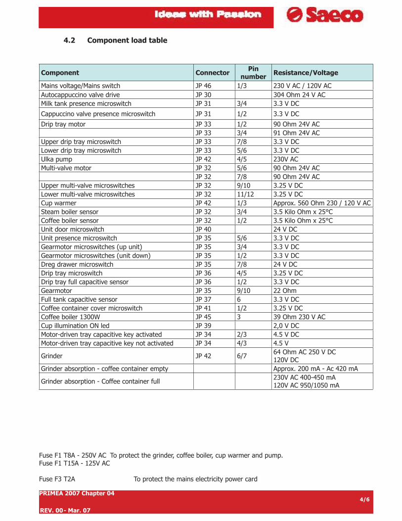
4.2 Component load table
Component Connector Pin number Resistance/Voltage
Mains voltage/Mains switch JP 46 1/3 230 V AC / 120V ACAutocappuccino valve drive JP 30 304 Ohm 24 V ACMilk tank presence microswitch JP 31 3/4 3.3 V DC
Cappuccino valve presence microswitch JP 31 1/2 3.3 V DC
Drip tray motor JP 33 1/2 90 Ohm 24V AC JP 33 3/4 91 Ohm 24V ACUpper drip tray microswitch JP 33 7/8 3.3 V DCLower drip tray microswitch JP 33 5/6 3.3 V DCUlka pump JP 42 4/5 230V ACMulti-valve motor JP 32 5/6 90 Ohm 24V AC JP 32 7/8 90 Ohm 24V ACUpper multi-valve microswitches JP 32 9/10 3.25 V DCLower multi-valve microswitches JP 32 11/12 3.25 V DCCup warmer JP 42 1/3 Approx. 560 Ohm 230 / 120 V ACSteam boiler sensor JP 32 3/4 3.5 Kilo Ohm x 25°CCoffee boiler sensor JP 32 1/2 3.5 Kilo Ohm x 25°CUnit door microswitch JP 40 24 V DCUnit presence microswitch JP 35 5/6 3.3 V DCGearmotor microswitches (up unit) JP 35 3/4 3.3 V DCGearmotor microswitches (unit down) JP 35 1/2 3.3 V DCDreg drawer microswitch JP 35 7/8 24 V DCDrip tray microswitch JP 36 4/5 3.25 V DCDrip tray full capacitive sensor JP 36 1/2 3.3 V DCGearmotor JP 35 9/10 22 OhmFull tank capacitive sensor JP 37 6 3.3 V DCCoffee container cover microswitch JP 41 1/2 3.25 V DCCoffee boiler 1300W JP 45 3 39 Ohm 230 V ACCup illumination ON led JP 39 2,0 V DCMotor-driven tray capacitive key activated JP 34 2/3 4.5 V DCMotor-driven tray capacitive key not activated JP 34 4/3 4.5 V
Grinder JP 42 6/7 64 Ohm AC 250 V DC 120V DC
Grinder absorption - coffee container empty Approx. 200 mA - Ac 420 mA
Grinder absorption - Coffee container full 230V AC 400-450 mA 120V AC 950/1050 mA
Fuse F1 T8A - 250V AC To protect the grinder, coffee boiler, cup warmer and pump.Fuse F1 T15A - 125V AC
Fuse F3 T2A To protect the mains electricity power card

REV. 00 - Mar. 07
4.3 Water circuit
5/6PRIMEA 2007 Chapter 04
Primea Touch Plus

REV. 00 - Mar. 07
Primea Touch /Ring
6/6PRIMEA Chapter 04

REV. 00 - Mar. 07
CHAPTER 5 TROUBLESHOOTING
REV.00 PRIMEA 2007 Chapter 05

REV. 00 - Mar. 07
4
2 3
1
5.1 Primea Touch Plus and Touch test functions
During the first 3 seconds after start-up of the appliance (or on exit from standby mode) the user can access test mode by pressing the keys in the sequence shown alongside.In test mode, the machine functions can be checked, and are divided into four macro-groups.
The display shows: - CPU card software version - Power card software version - Description of functions - Esc key to exit Test Mode - Version of boot loader on CPU
FUNCTION GROUP 2: - Multi-way valve (positioning) - Cappuccino valve (positioning) - Pump (ON/OFF)
FUNCTION GROUP 1: - Brew group (upwards/downwards) - Grinder (function) FUNCTION GROUP 3:
- Motor-driven tray (upwards/downwards) - Cup illumination (ON/OFF) - Cup warmer - Boilers (ON/OFF)
Shows soft-ware version
ESC
CPU print software version:V_00.00.00
power print software version:V_00.00.00
CPU print boot loader version:V_00.00.00
brew unitgrinder
Cup liftIllumination
heaters
Multi valveCapp.valve
Pump
SoftwareVersion
ESC
Brew groupGrinder
Cup liftIllumination
heaters
Multi valveCapp.valve
Pump
SoftwareVersion
ESC
1/20PRIMEA 2007 Chapter 05
The functions of the second water boiler do not apply to the Touch model.

REV. 00 - Mar. 07
5.1.1 Function group 1 - brew group, grinder, boiler power supply.
Function group 3 - drip tray, cup illumination, cup warmer, boiler supply
Function group 2 - multi-way valve, cappuccino maker valve, pump
Dispensing head home: brew group in home position Is home - rest position (Gearmotor micro.)Brew group work: brew group in brewing position. Is work - delivery position (gearmotor micro)Brew group: inserted - unit inserted (unit micro) Missing - unit missing (unit micro)Grinder go: grinder running.Grinder: Imp:000 - grinder pulses. Top open - coffee container cover open. Top closed- coffee container. cover closed. Impulses Grinder pulse control (min.60 - max. 200) in
steps of 05Med. aroma sets quantity of ground coffee
Multi valve left: Multi-way valve turns left Multi valve right: multi-way valve turns rightMultival:OK multi-way valve OK or faulty (ER)Pos1:Steam Steam setting (hot milk and froth)Pos2:St.Pre. Steam pressure before delivery of milk or frothPos3:Init Reset position - initialisationPos4:Coffee Coffee brew settingPos5:Hotwa. Hot water dispense settingPos6:Rinsing. Milk circuit autorinse positionCupp.valve next: Cappuccino valve commandpositionPos1:Init Reset position - initialisationPos2:Foam Milk frothing settingPos3:Milk Hot milk dispense settingpump: PumpTurbo:OK Pump OK or faulty (ER)Imp.:000 Turbine pulses (40 - 60 OK)Hz: 000Solenoid: Activation of electromagnet that closes the
milk door
Cuplift up: Tray up movementCuplift down: Tray downwards movementCuplift:Is bottom: Tray downwards (lower micro)Is Top tray up (upper micro)Key up: OFF ON/OFF-Up key pressedKey down: OFF ON/OFF-Down key pressed Illumination: cup illumination (press and hold)Cup warmer cup warmer plate (press and hold)Steam boiler: 1100W - powers steam boiler.Water boiler: 1300W - powers water boiler.Sensor:* Max 150
Key: In black: Keys In blue: Check status * See next page (sensors)
2/20PRIMEA 2007 Chapter 05
brew unitgrinder
cup liftillumination
heaters
multi valvecapp.valve
pump
softwareversion
ESC
inserted
Dregdraw:OKDoor:OKDripWater:OKTray miss:OK
ErrorsBrewunit
Grinder AImp:000
Top open
brew unithome
grindergo
ImpulsesMed. Aroma
75
brew unitwork
brew unitgrinder
cup liftillumination
heaters
multi valvecapp.valve
pump
softwareversion
ESC
Dregdraw:OKDoor:OKWaTank:OKWaLevel:OKDripWater:OKMilkTank:OKMilkDraw:OKTray miss:OK
Errors
Sensor
St:124:OKWa:100:OK
Multival:OKmultivalveleft
capp.valvenext
position
solenoid
multivalveright
pump
Pos3:InitMs: TopMs: BotCupp.ValvereachedPos1:Init
FlowmeterImp.:000Hz:000
brew unitgrinder
cup liftillumination
heaters
multi valvecapp.valve
pump
softwareversion
ESC
Dregdraw:OKDoor:OKWaTank:OKWaLevel:OKDripWater:OKMilkTank:OKMilkDraw:OKTray miss:OK
Errors
Sensor
St:103:OKWa:97:OK
Cupliftcuplift
up
cupliftdown
illuminationcup
heater
Is bottomKey up:OffKey down:Off
water heater(1300W)
steam heater
(1100W)

REV. 00 - Mar. 07
5.1.2 Microswitch and sensor check
Errors(Errors)Grounds drawer: Grounds drawer micro(Dregdraw:) OK Drawer present ER drawer missing
Service: Door microswitch(Door:) OK door closed ER door open
Water tank: Tank Micro (WaTank:) OK tank engaged ER tank empty or in reserve (see diagnostics)
Water level: Water level capacitive sensor(WaLevel) OK Water present ER Water low
Drip. tray: Drip tray capacitive sensor(DripWater:) OK drip tray empty ER drip tray full
milk tank: Milk tank door micro(MilkTank) OK milk tank door closed ER milk tank door open
Cappuccino valve: Milk tank + cappuccino valve micro(Milk Draw:) OK milk tank and cappuccino valve inserted ER milk tank and/or cappuccino valve not found
Drip. tray: Drip tray micro(no drip tray) OK tray present(Tray miss:) ER no tray
SensorsSt: steam Steam boiler temperature sensor (Touch Plus only) Number: current temperature OK Sensor connection ok ER sensor shorted or disconnected
Wa: water Water boiler temperature sensor Number: current temperature OK Sensor connection ok ER sensor shorted or disconnected
Dregdraw:OKDoor:OKWaTank:OKWaLevel:OKDripWater:OKMilkTank:OKMilk Draw:OKTray miss:OK
Errors
Sensor
St:100:OKWa:100:OK
3/20PRIMEA 2007 Chapter 05

REV. 00 - Mar. 07
5.2.1 Beverage counters
Total hot milk beverages• Total beverages not modifiable• Beverage dispense time (sec.) not modifiable
Total latte macchiato beverages• Total beverages not modifiable• Water used (ml.) not modifiable
Total cappuccino beverages• Total beverages not modifiable• Water used (ml.) not modifiable
Total espresso macchiato beverages• Total beverages not modifiable• Water used (ml.) not modifiable
Total hot water beverages• Total beverages not modifiable
Water used (ml.) not modifiableTotal caffelungo beverages
Total beverages not modifiableWater used (ml.) not modifiable
Total coffee beveragesTotal beverages not modifiableWater used (ml.) not modifiable
Total espresso beveragesTotal beverages not modifiableWater used (ml.) not modifiable
43
21
Water circuitemptying
System set-tings
Total counters
Exit diag-nostics menu
Diagnosticsmenu
Beverage-counters
auto testError
counters
Beverage settings
4/20PRIMEA Chapter 05
A window is displayed showing the following options:• Beverage counters• Total counters• Error counters• Beverage settings• System settings• Steamout (circuit emptying)• Auto test• Exit diagnostics menu
Description of options available
5.2 Touch Plus and Touch diagnosis function
Procedure for access to diagnostics mode.Turn the appliance off and then on again or exit standby mode to enter the diagnostics menu, according to
the sequence shown in the figure. When accessing the diagnostics menu, there is a timeout limit of 3 seconds between one selection and the next (1,2,3,4).
The functions of the second water boiler do not apply to the Touch model.

REV. 00 - Mar. 07
Total pre-ground coffee beveragesTotal beverages not modifiableWater used (ml.) not modifiable
Total all beveragesTotal beverages not modifiable
5.2.2 Total countersWater used since production (ml.) not modifiableWater used since last descaling (ml.) modifiableWater used since last descaling message (ml.) not modifiableWater used since last descaling (ml.) not modifiable
Water used counter (last) 0 ml. Water used counter (second last) 1 ml. Water used (third to last) 2 ml. not modifiable
Total descaler used not modifiableWater used by filter since last reset (ml.) modifiableWater used with water filter enabled since production (ml) not modifiableNumber of descalings (cycles) not modifiableNumber of dispensing head cleaning cycles not modifiableNumber of milk circuit rinse cycles not modifiableNumber of cappuccino valve cleaning cycles not modifiableWater filters used since production (cycles) not modifiableNumber of dispensing head removals (cycles) not modifiableBeverages up to descaling (cycles) modifiableMachine active time (sec.) not modifiableTemporary descaling counter not modifiableWater circuit emptying counter (cycles) not modifiable
5.2.3 Error counters (access submenu)The machine records the followingerrors (see also section 5.3)
01) Grinder 1 blocked02) Grinder 2 blocked03) Dispensing head blocked; up command04) Dispensing head blocked; down05) Pump flow rate error (fill circuit)07) Multivalve blocked08) Capp. valve. blocked09) Powercomm error (communication error with power card)10) Water boiler sensor disconnected11) Water boiler sensor short circuited12) Steam boiler sensor disconnected13) Steam boiler sensor short circuit14) Water boiler disconnected15) Steam boiler disconnected16) Both dispensing head microswitches active17) EEPROM read and write error18) Real time clock oscillator stopped19) No zero crossing in mains supply20) Cuplift both microswitches active
All these errors display the following submenuProduction errors not modifiableErrors since last service resettable – modifiableCurrent resettable – modifiable
Ringbuffer errors: the last 20 errors are saved. Error 1/20,2/20,3/20,4/20,5/20,6/20,7/20,8/20,9/20,10/20,11/20,12/20,13/20,14/20,15/20, 16/20,17/20,18/20,19/20,20.
5/20PRIMEA Chapter 05

REV. 00 - Mar. 07
5.2.4 Ring buffer repair code
Buffer history repair
This area records interventions of the Service Centres (up to a maximum of 10). The Service Centre enters the fault codes via PC as transmitted by Saeco I.G. (e.g: CLD01)
1. group errors 1. code errors 1. day errors 1. month errors 1. year errors
2................. 10. group errors 10. code errors 10. day errors 10. month errors 10. year errors
6/20PRIMEA Chapter 05
Machine status (all modifiable)
• 1 Prime circuit (yes/no)• 2 Water filter (not inserted/inserted)• 4 Unit full (yes/no)• 8 Display add coffee grinder 1 (yes/no)• 16 Display add coffee coffee grinder 2 (yes/no)• 32 Time format (am/pm)• 64 Standby (yes/no)• 128 Rinse (enable/disable)• 256 Cup illumination (enable/disable)• 512 Grinder 1 out of coffee (warning message management) sec.• 1024 Grinder 2 out of coffee (warning message management sec.• 2048 Milk circuit rinse required (yes/no)• 4096 Demo mode (disable/enable) command• 16384 Display icons (yes/no)• 32768 Warning tone ready (enable/disable)• 65536 Milk quality warning (enable/disable)• 131072 Key press tone (enable/disable)• Water filter activation suspended (yes/no)• Language selection on power-on (yes/no)• Milk circuit rinse

REV. 00 - Mar. 07
SYSTEM SETTINGSparameters
Unit of measurement Settings range
Default value
HOT MILKBeverage data modified by user yes/no NoMilk time seconds 0 ... 40 0Froth time seconds 0 ... 40 25LATTE MACCHIATOBeverage data modified by user yes /no NoTemperature low, high, medium mediumAroma medium, light, preground, strong mediumGrinding ratio percentage 0 ... 100 100Pre-brewing disabled, strong, normal normalWater turb. pulses. 50 ... 450 135Milk time seconds 0 ... 40 0Froth time seconds 0 ... 40 27CAPPUCCINOBeverage data modified by user yes /no NoTemperature low, high, medium mediumAroma medium, light, preground, strong mediumGrinding ratio percentage 0 ... 100 100Pre-brewing disabled, strong, normal normalWater turb. pulses. 50 ... 450 135Milk time seconds 0 ... 40 0Froth time seconds 0 ... 40 22ESPRESSO MACCHIATOBeverage data modified by user yes /no NoTemperature low, high, medium mediumAroma medium, light, preground, strong mediumGrinding ratio percentage 0 ... 100 100Pre-brewing disabled, strong, normal normalWater turb. pulses. 50 ... 450 135Milk time seconds 0 ... 40 0Froth time seconds 0 ... 40 5HOT WATERBeverage data modified by user yes /no NoWater turb. pulses. 50 ... 450 210CAFFE’ LUNGOBeverage data modified by user yes /no NoTemperature low, high, medium mediumAroma medium, light, preground, strong mediumGrinding ratio percentage 0 ... 100 100Pre-brewing disabled, strong, normal normalWater turb. pulses. 50 ... 450 440COFFEE’Beverage data modified by user yes /no NoTemperature low, high, medium medium
5.2.5 Beverage settings
PRIMEA Chapter 057/20

REV. 00 - Mar. 07
8/20
Aroma medium, light, preground, strong mediumGrinding ratio percentage 0 ... 100 100Pre-brewing disabled, strong, normal normalWater turb. pulses. 50 ... 450 280ESPRESSOBeverage data modified by user yes /no NoTemperature low, high, medium highAroma medium, light, preground, strong mediumGrinding ratio percentage 0 ... 100 100Pre-brewing disabled, strong, normal normalWater turb. pulses. 50 ... 450 165EXTRA MILKTime seconds 0 ... 40 5
PRIMEA Chapter 05

REV. 00 - Mar. 07
9/20PRIMEA Chapter 05
5.2.6 System settings
SYSTEM SETTINGS parameters
Unit of measurement Settings range Default value
SETTINGWater boiler temperature enabled °C 70 ... 150 130Water boiler temperature disabled °C 70 ... 150 115Steam boiler temperature enabled °C 70 ... 150 145Steam boiler temperature disabled °C 70 ... 150 130Average temperature in cup °C 70 ... 150 78Last use of dispensing head min/sec 0 - 59; 0 - 59 0Last use of dispensing head d/h 1-7; 0-23 0BEVERAGE PARAMETERSHot water flow rate (l/h) 5 ... 31 16touch : hot mik (pulse lenght) line-period 2 ... 30 5 (=100ms / 50Hz) touch : hot milk (pulse period) 20ms - steps 2 ... 126 60(=1200ms)plus + duo : hot milk (steam pressure time) seconds 0 ... 40 6plus + duo : hot milk (pulse lenght) line-period 2 ... 30 4(=80ms / 50Hz)plus + duo : hot milk (pulse period) 20ms - steps 2 ... 126 64(=1280ms)Milk level sensor delay times (do not modify) seconds 0 ... 20 4MILK CIRCUIT RINSEmilk circuit rinse new multiway valve (hot water) flow rate (l/h) 5 ... 31 16milk circuit rinse new multiway valve (pulse lenght) line-period 50 ... 450 150(=3000ms/50Hz)milk circuit rinse old multiway valve (dispense time) seconds 0 ... 40 10milk circuit rinse old multiway valve (steam pressure time) seconds 0 ... 40 6milk circuit rinse old multiway valve (pulse lenght) line-period 2 ... 30 2 (= 40ms / 50Hz)milk circuit rinse old multiway valve (pulse period) 20ms - steps 2 ... 126 32 (=640ms)MILK CIRCUIT CLEANINGMilk circuit (first use in day) day 1-31 1Milk circuit (first use in month) month 1-12 1Milk circuit (first use in year) year 2005-2099 2099Milk circuit cleaning (status) complete 0
Milk circuit cleaning (dispense time) 0 ... 45 45
Milk circuit cleaning (steam pressure time) 0 ... 40 6Milk circuit cleaning (pulse length) line-period 2 ... 30 2 (= 40ms / 50Hz)Milk circuit cleaning (pulse period) 20ms - steps 2 ... 126 32 (=640ms)Milk circuit cleaning (detergent wait time) minutes 0 ... 60 1DESCALING STATUSStatus complete, dec. rinse start, dec. finished, normal quantity, start. quantity DISPENSING HEAD CLEANINGStatus complete, finished dispensing, quantity 4-3-2-1 dispensed
Machine status * complete ---Language 0 ... 11 0Water hardness hardness setting 1 ... 4 3Display brightness (colour) brightness setting 50 ... 100 80Display brightness (black) brightness setting 2690 ... 2890 2740Cup warmer disabled, always on, off, in standby disabled

REV. 00 - Mar. 07
5.2.7 Emptying water circuit
This option must be run when the coffee maker is delivered by courier in periods subject to winter temperatures.This function prevents damage to the appliance caused by very low temperatures.The cycle empties the water circuit by means of the following sequence of operations performed automatically.
Selection of functions in diagnostics menu. 1. The multivalve must be in coffee position.2. Both boilers reach the temperature of 130°C3. The brew group stops in the brew position (UP) for 3 sec. 4. The unit returns to the home position (DOWN)5. The multivalve sets to the hot water position for 1 sec.6. The multivalve sets to the steam position for 1 sec.
10/20PRIMEA Chapter 05
* Enter machine status
** The day, hours and minutes of machine start-up and shutdown can be programmed in three time bands.
Grinder adjustment A (med. aroma) grinder pulses 60 ... 200 75Grinder adjustment B (med. aroma) grinder pulses 60 ... 200 60Off time hours and minutes 0-3; 0-59 3Calendar used** days, hours, seconds complete 0Production date dd/mm/yy not modifiable not modifiableService date dd/mm/yy complete 0Empty milk alert minutes 0 ... 60 20Milk rinse warning time minutes 5 ... 240 20Power board status complete 17Aqua Prima water filter dd/mm/yy complete 2006Aqua Prima water filter - last appliance start-up dd/mm/yy complete 2006 Stop coffee grounds no. grounds 0 ... 25 24Coffee grounds counter no. grounds 0 ... 25 24Water reserve limit turbine pulses 0 ... 2000 750Water reserve counter turbine pulses 0 ... 2000 0
Software versioncpu print v_--.--.--cpu bootloader print v_--.--.--power print v_--.--.--
Serial number complete

REV. 00 - Mar. 07
5.2.8 Auto test
On selection of this function, an automatic test is run on the machine functions, with results reported on the display. Before starting the test, all drawers and the tank must be inserted, all service doors closed and the relative recipients must be filledwith water and coffee.
Test type Description Message if function OK
Error message
2.7.1 External ram test
Check CPU ram successful ! failed !
2.7.2 flash test Check CPU flash memory successful ! failed !2.7.3 Eeprom test Check non volatile memory with machine settings successful ! failed !2.7.4 rtc test Check real time clock successful ! failed !2.7.5 Cup lift test upwards
The motor-driven tray moves up and engages the upper microswitch
successful ! failed !
2.7.6 cup lift test downwards
The motor-driven tray moves down and engages the lower microswitch
successful ! failed !
2.7.7 Capp valvetest
Check correct operation of the cappuccino valve and relative microswitch
successful ! failed !
2.7.9 multivalvetest
Check correct operation of multivalve and relative microswitches
successful ! failed !
2.7.10 pump test Check pump and turbine operation.WARNING: hot water delivered
successful ! failed !
2.7.11 Grinder test Check grinderand coffee presenceè, as well as hall sensor which counts pulses.
successful ! failed !
2.7.12 Brew group test upwards
Check of ascent of unit and activation of the upper limit microswitch
successful ! failed !
2.7.13 Brew group downwards
Check of descent of unit and activation of the lower limit microswitch.
successful ! failed !
2.7.14 Water heater test
Check and inspection of power to coffee/water boiler, if the sensor detects increase in temperature.
successful ! failed !
2.7.15 Steam heater test(Touch Plus only)
Check and inspection of power to steam boiler, if the sensor detects increase in temperature.
successful ! failed !
At the end of the automatic cycle, you can “repeat the automatic test” or “exit the test” as required.
Exit diagnostics
On selection of this option, the system exits the diagnostics menu and returns to the normal machine functions.
11/20PRIMEA Chapter 05

REV. 00 - Mar. 07
MENU
5.3 Ringtest function
Tmode L1Inputs 1245679ABCDEFGH
AROMA
ESCUP
DOWN
During the fi rst 3 seconds after start-up of the appliance (or on exit from standby mode) the user can access test mode by pressing the keys in the sequence shown alongside.Turn the touch-ring (P) (I-Pod) for access to each different level.
P
OK Keyboard
Key test MENU The display indicates no. 1 AROMA The display indicates no. 2 OK The display indicates no. 3 UP The display indicates no. 5 DOWN The display indicates no. 6 UPWARD The display indicates no. 9 (motor-driven tray capacitive key up). DOWNWARD The display indicates no. A (motor-driven tray capacitive key down)
Level 1 Microswitch and INPUT - OUTPUT sensor control
- BREWUNIT (unit located) The display indicates no. 1
- WATERLEVEL (water level detection) The display indicates no. 4
- BU_BOOR (close service door) The display indicates no. 5
- DREGDRAWER (dreg drawer located) The display indicates no. 6
- DRIPTRAY_PRES (drip tray located) The display indicates no. 7
- DRIPTRAY_LEVEL (drip tray level detected) The display indicates no. 8
- CUPLIFT_TOP (stroke end position motor-driven tray upper sensor). The display indicates C
- CUPLIFT_BOTTOM (stroke end position motor-driven tray lower micro) The display indicates D
12/20PRIMEA Chapter 05
4
32
1

REV. 00 - Mar. 07
- CAPP_DOOR_CLOSED (milk tank door closed). The display indicates E
- CAPP_DOOR_CLOSED+CAPP_PRES (door closed milk tank and cappuccino valve. The display indicates F
- COFFEE_BEANS_DOOR_CLOSED (coffee container lid closed). The display indicates G
- TANK_PRES (water tank) The display indicatesH
Level 2 Check gearmotor moving the unit
- PRESS UP (unit up) The display indicates no. 5 when the upper micro of the gearmotor is enabled.
- PRESS DOWN (unit down) The display indicates no. 6 when the lower micro of the gearmotor is enabled. Torque absorption is indicated during movement (max 350 mA)
No. 3Test grinder and pump
- PRESS ESC KEY (the pump starts). The display indicates turbine pulses
- PRESS OK KEY (excites milk tank solenoid valve). The display indicates SOLENOID ACTIVATED and no.3
- PRESS AROMA KEY (grinder starts)
- PRESS UP OR DOWN KEY (to vary the aroma)
Level 4Test water boiler and cup warmer
- PRESS THE UP KEY (water boiler is filled). The display shows the change to the temperature.
- PRESS THE ESC KEY (cup warmer comes on) You can feel the cup warmer heating up
Level 5Test multivalve
- PRESS THE UP KEY (position changed in clockwise direction)
- PRESS THE DOWN KEY (the position changes in anticlockwise direction)
- PRESS THE ESC KEY (returns to water position)
Level 6Test cappuccino maker
- PRESS THE UP KEY (moves to position 0)
- PRESS THE DOWN KEY (moves to position 1)
13/20PRIMEA Chapter 05

REV. 00 - Mar. 07
Level 7Motor-driven tray test
- PRESS THE UP KEY (lower capacitive key) KEY 9
- PRESS THE DOWN KEY (upper capacitive key) KEY A The display indicates D = lower stroke end position micro The display indicates C = upper stroke end position micro The display indicates A = upper capacitive key The display indicates 9 = lower capacitive key
Level 8Display contrast test
- PRESS THE UP KEY (increase contrast)
- PRESS THE DOWN KEY (reduce contrast)
Level 9Display backlighting test
- PRESS THE UP KEY (increase intensity)
- PRESS THE DOWN KEY (reduce intensity)
Level BThis procedure restores the default parameters of the appliance with the exception of:
- Coffees made since production counter- Errors since production counter- Descaler used- Water used since last descaling, from the last to the second last, from the second last to the third from last, from
the third from last to the fourth from last- Number of descalings performed- Number of clean cycles run on unit- Number of times unit has been removed- Seconds counter for total time machine switched on
Level CLanguage test
- PRESS THE UP OR DOWN KEY (select the sequence of messages in each language)
- PRESS OK KEY (select language)
LEVEL DTest steamout
-PRESS OK KEY (prepares appliance for packaging) Empties water circuit and raises motor-driven tray. LEVEL E- EXIT
A
9
14/20PRIMEA Chapter 05

REV. 00 - Mar. 07
PRIMEA Chapter 05
43
21
A window is displayed showing the following options:• Beverage counters• Total counters• Error counters• Beverage settings• System settings• Exit diagnostics menu
Description of options available
5.4 Ring diagnosis function
Procedure for access to diagnostics mode.Turn the appliance off and then on again or exit standby mode to enter the diagnostics menu, according to
the sequence shown in the fi gure.When accessing the diagnostics menu, there is a timeout limit of 3 seconds between one selection and the
5.4.1 Beverage counters
1.1 Total espresso beveragesTotal beverages not modifi ableWater used (ml.) not modifi able
1.2 Total coffee beveragesTotal beverages not modifi ableWater used (ml.) not modifi able
1.3 Total caffè lungo beveragesTotal beverages not modifi ableWater used (ml.) not modifi able
1.4 Total latte macchiato beverages1.4.1 Total beverages not modifi able1.4.2 Water used (ml.) not modifi able
1.5 Total cappuccino beverages1.5.1 Total beverages not modifi able1.5.2 Water used (ml.) not modifi able
1.6 Total espresso macchiato beverages1.6.1 Total beverages not modifi able1.6.2 Water used (ml.) not modifi able
1.7 Total hot milk beverages1.7.1 Total beverages not modifi able1.7.2 Dispense time (sec.) not modifi able
1.8 Total hot water beverages1.8.1 Total beverages not modifi able
Water used (ml.) not modifi able
MENU
2
4
1
3
15/20

REV. 00 - Mar. 07
PRIMEA 2007 Chapter 05
1.9 Total all beverages not modifiable1.10 Total descaler used (ml) not modifiable
5.4.2 Total counters
2.1 Water used since production (ml.) not modifiable2.2 Water used since last descaling (ml.) not modifiable2.3 Water used since second last descaling (ml.) not modifiable2.4 Water used since third from last descaling (ml.) not modifiable2.5 Number of descalings (cycles) not modifiable2.6 Number of dispensing head cleaning cycles not modifiable2.7 Number of cappuccino valve cleaning cycles not modifiable2.8 Number of dispensing head removals (cycles) not modifiable2.9 Machine active time (sec.) not modifiable
5.4.3 Error counters (access submenu)
The appliance records the following errors
3.1) Grinder 1 blocked3.3) Dispensing head blocked; up command (Work)3.4) Dispensing head blocked; down command (Home)3.5) Water circuit blocked3.6) Multivalve error3.8) Cappuccino valve blocked3.10) Boiler sensor disconnected3.11) Water boiler sensor shortcircuited3.14) Water boiler temperature error3.16) Both microswitches activated on dispensing head3.17) Memory error3.18) Clock error3.19) No zero crossing3.20) Cuplift error (motor-driven tray)
All these errors display the following submenuProduction errors not modifiableErrors since last service resettable – modifiable
3.21) Error history: the last 20 errors are savedand coded from 3.21.1 to 3.21.20
16/20

REV. 00 - Mar. 07
SYSTEM SETTINGSparameters
Unit of measurement Settings range Default value
4.1 ESPRESSSO4.1.1 Temperature low, high, medium medium
4.1.2 Aroma medium, light, preground, strong strong4.1.3 WATER turb. pulses. 70 ... 450 STD 165 IT 1104.2 COFFEE4.2.1 Temperature low, high, medium medium
4.2.2 Aroma medium, light, preground, strong medium4.2.3 WATER turb. pulses. 70 ... 450 STD 280 IT 2004.3 CAFFE LUNGO4.3.1 Temperature low, high, medium medium
4.3.2 Aroma medium, light, preground, strong medium4.3.3 WATER turb. pulses. 70 ... 450 STD 440 IT 3304.4 ESPRESSO MACCHIATO4.4.1 Temperature low, high, medium medium
4.4.2 Aroma medium, light, preground, strong medium4.4.3 WATER turb. pulses. 70 ... 450 STD 165 IT 1104.4.4 Milktime seconds 2 ... 50 STD 11 IT 64.5 LATTE MACCHIATO4.5.1 Temperature low, high, medium medium
4.5.2 Aroma medium, light, preground, strong medium4.5.3 WATER turb. pulses. 70 ... 450 STD 280 IT 2004.5.4 Milk time seconds 2 ... 50 204.6 CAPPUCCINO4.6.1 Temperature low, high, medium medium
4.6.2 Aroma medium, light, preground, strong medium4.6.3 WATER turb. pulses. 70 ... 450 STD 280 IT 2004.6.4 Milk time seconds 2 ... 50 184.7 HOT MILK4.7.1 Milk time seconds 2 ... 50 244.8 HOT WATER4.8.1 Water turb. pulses. 70 ... 450 330
5.4.4 Ring product settings
17/20PRIMEA Chapter 05

REV. 00 - Mar. 07
18/20PRIMEA Chapter 05
5.4.5 Ring system settingsSYSTEM SETTINGS
parametersUnit of
measure Settings range Default valueSETTINGWater boiler temperature enabled °C 70 ... 150 130Water boiler temperature disabled °C 70 ... 150 115Steam boiler temperature enabled °C 70 ... 150 150Steam boiler temperature disabled °C 70 ... 150 130Normal cup temperature °C 70 ... 150 78BEVERAGE PARAMETERSHot water flow rate (l/h) 5 ... 31 18Hot milk (pulse length) line-period 1 ... 9 5 (=100ms/50Hz)Hot milk (pulse period) 20ms - steps 5 ... 250 60(=1200ms)MILK CIRCUIT RINSE Dispense time seconds 0 ... 40 10Pulse lenght line-period 1 ... 3 1 (= 20ms / 50Hz)Pulse period 20ms - steps 5 ... 250 15 (=300ms)MILK CIRCUIT CLEANINGMilk circuit cleaning (dispense time) 0 ... 40 10
MILK CIRCUIT CLEANING MESSAGEScleaning time seconds 30
days before notification days 14
days till block days 21GRINDER SETTINGmedium aroma pulses 60 ... 200 100
Water reserve limit turbine pulses 0 ... 2000 750Stop coffee grounds nr. grounds 0 ... 25 24Coffee grounds counter nr. grounds 0 ... 25 24Descaling counter litres 0 300Serial number

REV. 00 - Mar. 07
19/20PRIMEA 2007 Chapter 05
5.5 Error messages for Service personnelC
ode
App
licab
le m
odel
s:P
rim
ea-O
dea-
Tale
aB
rief
des
crip
tion
Des
crip
tion
01Al
l mod
els
Grin
der
1 bl
ocke
dTh
e gr
inde
r is
blo
cked
(bu
rrs
jam
med
or
sens
or n
ot r
eadi
ng p
rope
rly).
02Pr
imea
Grin
der
2 bl
ocke
dTh
e gr
inde
r is
blo
cked
(bu
rrs
jam
med
or
sens
or n
ot r
eadi
ng p
rope
rly).
03Al
l mod
els
Dis
pens
ing
head
blo
cked
in w
ork
posi
tion
Mic
rosw
itch
not
rele
ased
in u
p po
sitio
n af
ter
3”, t
orqu
e er
ror
tryi
ng t
o m
ove
dow
n, d
esce
nt t
ime
out
exce
eded
04Al
l mod
els
Dis
pens
ing
head
blo
cked
in h
ome
posi
tion
Mic
rosw
itch
not
rele
ased
in d
own
posi
tion
afte
r 3”
, tor
que
erro
r tr
ying
to
mov
e up
, asc
ent
time
out
exce
eded
05Al
l mod
els
Wat
er c
ircui
t bl
ocke
dN
o w
ater
in t
urbi
ne06
Prim
eaM
ultiv
alve
err
orM
ultiv
alve
è b
lock
ed
08Pr
imea
Capp
ucci
no v
alve
blo
cked
The
capp
ucci
no v
alve
has
faile
d to
res
et b
ecau
seit
has
faile
d to
exc
ite t
he
mic
rosw
itch.
09Pr
imea
Com
mun
icat
ion
erro
r be
twee
n CP
U a
nd
POW
ERCo
mm
unic
atio
n in
terr
upte
d fo
r m
ore
than
2 s
econ
ds
10-1
1Al
l mod
els
Vario
us s
enso
r er
rors
Wat
er b
oile
r se
nsor
s sh
orte
d or
in o
pen
circ
uit
12-1
3Pr
imea
Vario
us s
enso
r er
rors
Stea
m b
oile
r se
nsor
s sh
orte
d or
in o
pen
circ
uit
14-1
5Al
l mod
els
Vario
us t
empe
ratu
re e
rror
sBo
iler
tem
pera
ture
s ou
t of
con
trol
16Al
l mod
els
Both
mic
rosw
itche
s ac
tivat
ed o
n di
spen
sing
he
adTh
e w
ork
and
hom
e m
icro
switc
hes
have
bot
h be
en a
ctiv
ated
17Al
l mod
els
Mem
ory
erro
rIm
poss
ible
to
read
or
writ
e to
e2p
rom
18Al
l mod
els
Cloc
k er
ror
Mem
ory
defe
ct o
r im
poss
ible
to
set
19Al
l mod
els
No
zero
cro
ssin
gN
o ze
ro c
ross
ing
on c
ard,
cou
ld b
e ca
used
by
pow
er c
ard
20Al
l mod
els
Cup
lift
erro
rTh
e tw
o st
roke
end
pos
ition
mic
rosw
itche
s ar
e ac
tivat
ed a
t th
e sa
me
time
On
mod
els
in t
he n
ew P
rimea
, Tal
ea a
nd O
dea
rang
es, e
rror
s re
cord
ed c
an b
e vi
ewed
on
the
disp
lay
(dur
ing
diag
nosi
s) o
r on
a P
C (w
ith p
rogr
amm
er).
The
fol-
low
ing
are
save
d:
A) T
he la
st 2
0 er
rors
to b
e re
cord
edB
) Tot
al n
umbe
r of e
rror
s (no
t all
mod
els)
• Si
nce
prod
uctio
n (to
tal)
• Si
nce
last
serv
ice
(par
tial)
• C
urre
nt

REV. 00 - Mar. 07
5.6 Problems, causes, remedies
HELP MESSAGES DISPLAYED HOW TO RESET MESSAGETurn the appliance off and on to solve the problem Switch off and after 30 sec. turn on the appliance to
restore normal operating conditions.
Call the Service Centre Problem requiring assistance of Service Centre
Insert drip tray Insert drip tray
Close coffee bean hopper lid Close the coffee bean hopper lid to enable delivery of any beverage.
Insert ground coffee This message guides the user when this type of cof-fee has been selected during personalised beverage programming.
Insert dispensing head Insert dispensing head in seat
Insert coffee grounds drawer Insert coffee grounds drawer
Empty coffee grounds drawer Remove coffee grounds drawer and empty.N.B: The coffee grounds drawer must only be emptied when the appliance is switched on. The drawer must be removed for at least 5 seconds. If the drawer is emptied when the appliance is switched off the mes-sage is not reset.
Close side door Close service door.
Fill water tank Fill tank
Empty drip tray below dispensing head Empty drip tray
Insert milk tank Insert container in milk compartment
Prime circuit Start filling water circuit automatically. The appliance will automatically try tofill the circuit 5 times; if it fails, contact the Service Centre.
The descaling cycle did not run correctly Repeat the operation as described in the relative chapter in the instruction booklet.
Replace Aqua Prima filter This message is only displayed if the filter control is enabled (see instruction booklet).Replace the filter if:1) 60 litres of water have been dispensed.2) 90 days have elapsed since installation.3) 20 days have elapsed since the coffee maker was
last used.
The cleaning cycle did not run correctly Repeat the operation as described in the relative chapter in the instruction booklet.
Insert cappuccino valve Insert cappuccino valve in milk compartment
Rinse milk tank Clean container after use
Descale appliance Run descaling cycle
Standby Press “ start”
20/20PRIMEA 2007 Chapter 05

REV. 00 - Mar. 07
CHAPTER 6OPERATING
LOGIC
REV.00 PRIMEA Chapter 05

REV. 00 - Mar. 07
6.1 Multi-way valve
1/9
Touch Plus multi-way valve opening operating diagram
Two
fact
ors
com
bine
to
give
the
five
pha
ses
of t
he m
ultiw
ay v
alve
:1)
Act
ivat
ion
(or
not)
of
two
mic
rosw
itche
s on
the
mul
tival
ve.
2) D
irect
ion
of r
otat
ion
of t
he m
ultiv
alve
.
PRIMEA Chapter 06
5
Hea
ter
1
Hea
ter
2
Mul
ti-w
ay
Auto
capp
uccin
o va
lve Ca
ppuc
cino
mak
er
Milk
con
tain
er
Hea
ter
pin
Pres
sblo
ck
4 3 2 1uvsg
2u
vsg
34 1
PH
ASE
-2
STEA
M
5
PH
ASE
-1
MIC
RO
1
PR
E-LO
AD
PH
ASE
0M
ICR
O 1
an
d 2
DR
AIN
UN
IT
PH
ASE
+2
MIC
RO
1
HO
T W
ATE
R
PH
ASE
+1
MIC
RO
2
CO
FFEE
2u
vsg
34 15
2u
vsg
34 15
2u
vsg
34 15
2u
vsg
34 15
MIC
RO
2
1=
hot
wat
er a
nd s
team
boi
ler
outle
t2
= h
ot w
ater
inle
t fr
om c
offe
e/w
ater
boi
ler
3=
hot
wat
er t
o br
ew u
nit
to m
ake
coff
ee4
= h
ot w
ater
to
disp
ense
pip
e5
= s
team
inle
t fr
om s
team
boi
ler
uv=
ste
am o
utle
t to
aut
ocap
pucc
ino
valv
esg
= u
nit
wat
er d
rain
PH
ASE
+3
MIC
RO
2
AU
TOR
INSE
2u
vsg
34 15
Pos
.1P
os.2
Pos
.3P
os.4
Pos
.5P
os.6
MIC
RO
1
MIC
RO
2
AU
TOR
INSE

REV. 00 - Mar. 07
Ring andTouch multi-way valve opening operating diagram
2/9PRIMEA 2007 Chapter 06
Two
fact
ors
com
bine
to
give
the
five
pha
ses
of t
he m
ultiw
ay v
alve
:1)
Act
ivat
ion
(or
not)
of
two
mic
rosw
itche
s on
the
mul
tival
ve.
2) D
irect
ion
of r
otat
ion
of t
he m
ultiv
alve
.
5
Hea
ter
Mul
ti-w
ay
Auto
capp
uccin
o va
lve Ca
ppuc
cino
mak
er
Milk
con
tain
er
Hea
ter
pin
Pres
sblo
ck
4 3 2 1uvsg
2u
vsg
34 1
PH
ASE
-2
STEA
M /
A
UTO
RIN
SE
5
PH
ASE
-1
MIC
RO
2
DR
AIN
PH
ASE
0M
ICR
O 1
an
d 2
DR
AIN
UN
IT
PH
ASE
+2
MIC
RO
1
HO
T W
ATE
R
PH
ASE
+1
MIC
RO
2
CO
FFEE
2u
vsg
34 15
2u
vsg
34 15
2u
vsg
34 15
2u
vsg
34 15
MIC
RO
1
1=
ste
am o
utle
t fo
r bo
iler
drai
nage
2
= h
ot w
ater
inle
t fr
om w
ater
boi
ler
3=
hot
wat
er t
o br
ew u
nit
to m
ake
coff
ee4
= h
ot w
ater
to
disp
ense
pip
e5
= s
team
out
uv=
outle
t cl
osed
sg=
uni
t w
ater
dra
in
Pos
.1P
os.2
Pos
.3P
os.4
Pos
.5
Dis
sipa
ter
Pres
sblo
ck
BO
ILER
DR
AIN
Af
ter
stea
m p
rodu
ctio
n (e
.g:
capp
ucci
no)
the
boile
r dr
ain
disc
harg
es s
team
into
the
drip
tra
y w
ith c
oolin
g vi
a th
e di
ssip
ater
.
The
boile
r is
re-
load
ed t
o en
able
del
iver
y of
cof
fee
or w
ater
.
MIC
RO
1
MIC
RO
2
AU
TOR
INSE

REV. 00 - Mar. 07
6.2 Autocappuccino
The autocappuccino system enables the automatic preparation of cappuccino, latte macchiato, caffè macchiato and hot milk.
The milk tank (A), with a capacity of approx. 0.4 l. is removable to enable storage of the contents in the fridge when not used.
At the time of cappuccino preparation, the milk is collected directly from the milk tank (A), whisked by the action of the steam and delivered to the relative dispensing head.
The holes that deliver the milk enable simultaneous preparation of two cappuccinos
Two microswitches, when activated, indicate:1. Closure of the milk tank2. Presence of milk tank and cappuccino valve
After delivery of a milk-based product, a circuit rinse is proposed(if it is not rinsed within 20 minutes, the appliance blocks all milk-based beverages).
If no milk-based beverages have been dispensed in the last 14 days, the appliance requests that the milk circuit is cleaned with a cleaning tablet / powder. (if this is not done, after 21 days all products are blocked).
3/9PRIMEA 2007 Chapter 06
A

REV. 00 - Mar. 07
The system consists of a motor-driven valve (B), which opens orifice (C) to allow air to enter and remove milk from inside the cappuccino maker. Motor (1) is a stepper motor which resets
the position after each beverage is dis-pensed.
Air/milk flow regulator which can be turned to clean the sur-face of the hole or removed for a more thorough clean.
4/9PRIMEA 2007 Chapter 06
Air flow/milk regulator
The seal between the body of the cappuccino valve and the dispensing head is guaranteed by an O-ring.
The Venturi effect is generated by a special thermoplastic component.
The post-chamber controls the flow of milk, eliminating any spray during milk delivery.
C
1
REV. 00 - Mar. 07
5/9PRIMEA 2007 Chapter 06
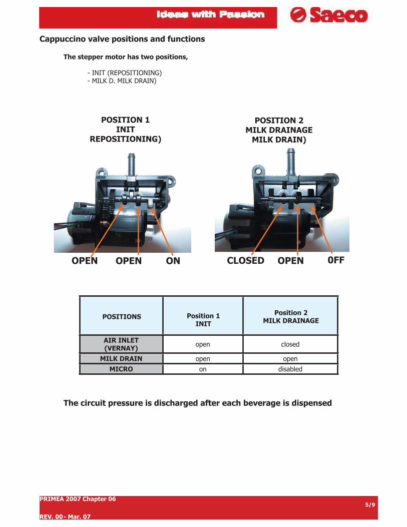
POSITIONS Position 1 INIT
Position 2MILK DRAINAGE
AIR INLET(VERNAY) open closed
MILK DRAIN open open
MICRO on disabled
Cappuccino valve positions and functions
POSITION 2MILK DRAINAGE
MILK DRAIN)
POSITION 1 INIT
REPOSITIONING)
The circuit pressure is discharged after each beverage is dispensed
The stepper motor has two positions, - INIT (REPOSITIONING) - MILK D. MILK DRAIN)
ON CLOSED OPEN 0FFOPENOPEN

REV. 00 - Mar. 07
6.3 Motor-driven tray
6/9
The movement of the motor-driven tray is mechanical by means of a stepper motor (1) in 24V DC, controlled by two capacitive touch sensors (2) located at the front of the tray.The two microswitches (3) are for the limit switch, and operation can be checked in test mode (see Section 5.1)
3
1
2
3
3
2
3
PRIMEA 2007 Chapter 06

REV. 00 - Mar. 07
7/9
Operating logic with “AQUA PRIMA” filter for Primea Ring
When use of the “aqua prima” filter is selected on the user menu or via the control panel, the system water count logic is as follows:If the “aqua prima” function has been enabled, the electronics perform a pulse count of the turbine, recording one pulse every 2 revolutions. If the “aqua prima” function has been disabled, the electronics perform a pulse count of the turbine, recording one pulse every revolution.The graph below illustrates this function:
6.4 Aqua Prima
PRIMEA 2007 Chapter 06
DESCALING
Hardness Water hardness Descaling frequency Descaling frequencywhen usingAqua Prima
1 Soft water (up to 7ºdH) Approx. every 3 months/ 120 l (31.6 Gal)
Approx. every 3 months/ 150 l (39.5 Gal)
2 Medium water (7º-14ºdH) Approx. every 2 months/ 90 l (23.75 Gal)
Approx. every 2 months/ 120 l (31.6 Gal)
3 Hard water (15º-21ºdH) Approx. every 6 weeks/ 60 l (15.8 Gal)
Approx. every 6 weeks/ 90 l (23.75 Gal)
4 Very hard water (over 21ºdH) Approx. every 4 weeks/ 30 l (7.9 Gal)
Approx. every 4 weeks/ 60 l (15.8 Gal)
When the “Aqua Prima” is enabled, an additional 30l of water can go through before descaling is required (see table)
Operating logic with “AQUA PRIMA” filter for Primea Ring Duo - Touch Plus and Touch
Descaling
Hardness Water hardness Descaling frequency Descaling frequencywhen usingAqua Prima
1 Soft water (up to 7ºdH) Approx. every 3 months/ 120 l (31.6 Gal)
Approx. every 3 months/ 240 l (63.2 Gal)
2 Medium water (7º-14ºdH) Approx. every 2 months/ 90 l (23.75 Gal)
Approx. every 2 months/ 180 l (47.4 Gal)
3 Hard water (15º-21ºdH) Approx. every 6 weeks/ 60 l (15.8 Gal)
Approx. every 6 weeks/ 120 l (31.6 Gal)
4 Very hard water (over 21ºdH) Approx. every 4 weeks/ 30 l (7.9 Gal)
Approx. every 4 weeks/ 60 l (15.8 Gal)

REV. 00 - Mar. 07
6.5 SBS valve
8/9PRIMEA 2007 Chapter 06
Beverage dispensingThe SBS brew unit valve (see fig. 2) can be used to vary (increasing or decreasing depending on the position of the knob) the amount of water passing through the brew unit. This adjusts coffee brewing time (extraction time) and consequently the intensity of taste, keeping the cream quality constant.
FunctionWith the SBS valve in the open position, coffee is accumulated in the membrane valve due to a low back-pressure of the SBS valve. Consequently the membrane valve needle remains in the maximum open position, due to resistance of the spring. Coffee comes out quickly (see Fig. 3).With the SBS valve in the closed position, coffee is accumulated on the membrane of the valve with a consequent increase in pressure in the valve. The spring yields to the back-pressure and the needle then reduces the coffee passage (see Fig. 4).
Fig.4
Fig.1 Fig.2
Fig.3

REV. 00 - Mar. 07
To ensure correct operation of the SBS valve a caffe lungo should be made. During preparation of the latter, check the difference in speed of delivery between the maximum and minimum positions.The difference in dispensing speed is approx. 2.5 times greater (and therefore VERY obvious!!)
9/9PRIMEA 2007 Chapter 06
Checking function of SBS valve

REV. 00 - Mar. 07
CHAPTER 7COMPONENT
ASSEMBLY AND DISASSEMBLY
REV.00 PRIMEA 2007 Chapter 07

REV. 00 - Mar. 07
7.1 Top cover
Open cover (A).Remove pre-ground shoot (B).Remove lid latch (C).Loosen the three fixing screws of the hopper, complete with cover.
Release the end section of the top cover by loosening the three screws (P).
A
BC
1/22PRIMEA 2007 Chapter 07

REV. 00 - Mar. 07
Move the drip tray to the lower limit position.Disassemble the start touch sensors (E).Remove the door (F) protecting the connec-tion socket of the setting device, by means of a #10 torx driver.Loosen the screws as indicated.
7.2 Right-side cover
Raise the rear section of the top cover slightly.
Push the upper section of the right side cover upwards to release from hooks (C) from slots (B).To facilitate release, push the front section of the cover downwards.
2/22PRIMEA 2007 Chapter 07

REV. 00 - Mar. 07
7.3 Left-side cover
Loosen the screws as indicated.
Raise the rear section of the top cover slightly.
Push the upper section of the left side cover up-wards to release from hooks (C) from slots (B).To facilitate release, push the front section of the cover downwards.
3/22PRIMEA 2007 Chapter 07
REV. 00 - Mar. 07
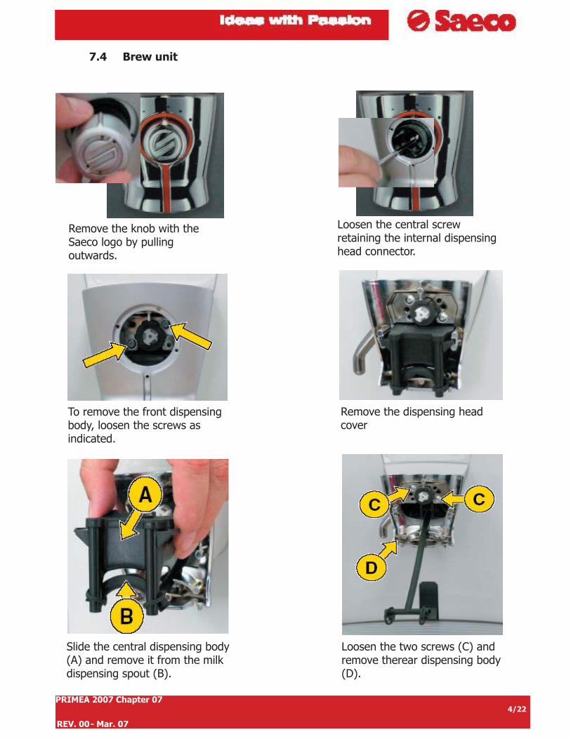
7.4 Brew unit
Slide the central dispensing body (A) and remove it from the milk dispensing spout (B).
Loosen the two screws (C) and remove therear dispensing body (D).
Remove the knob with the Saeco logo by pulling outwards.
Loosen the central screw retaining the internal dispensing head connector.
To remove the front dispensing body, loosen the screws as indicated.
Remove the dispensing head cover
4/22PRIMEA 2007 Chapter 07
REV. 00 - Mar. 07
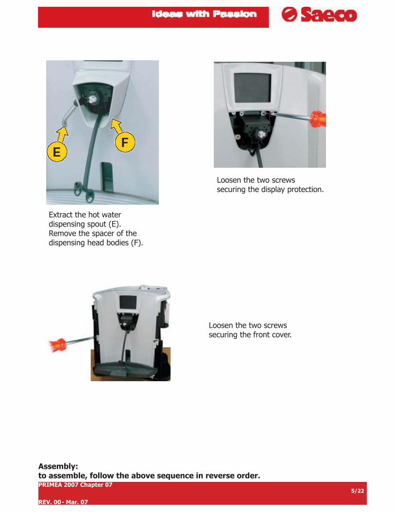
Extract the hot water dispensing spout (E).Remove the spacer of the dispensing head bodies (F).
Loosen the two screws securing the display protection.
Loosen the two screws securing the front cover.
5/22PRIMEA 2007 Chapter 07
Assembly:to assemble, follow the above sequence in reverse order.

REV. 00 - Mar. 07
7.5 Electronics
To access board (F) loosen the board protection screws (G).
6/22
Loosen the screws as indicated and remove all connectors.
PRIMEA 2007 Chapter 07

REV. 00 - Mar. 07
7.6 Gearmotor
Remove the casing (A) by loosening the three screws.
Loosen the two screws and remove the boiler valve (B).
To remove protection plate (C), remove the indicated screws.
The following are located inside the compartment protected by the guard: - Brew drive (A) with gears (B) and (C) for
transmission and timing of the dispensing head;
- grounds drawer present microswitch (D); - Dispensing head present microswitch (E); - Microswitch (F) - dispensing head in home
position; - Microswitch (G) - dispensing head in
dispensing position.Remove the gear (C) that meshes with the brew drive transmission shaft. Remove the large gear (B).Pull out the brew drive (A) complete with transmission shaft (H).
7/22PRIMEA 2007 Chapter 07

REV. 00 - Mar. 07
Install the brew drive and transmission shaft, inserting the guides (L) in the relative seat. Flat side of the guide face up.
Insert the gear (B), taking care that the arrow stamped on the element is within the opening that contains pin (P).
Insert the gear so that it meshes with the transmission shaft.
Refit the protection casing (C) and tighten the screws
8/22PRIMEA 2007 Chapter 07

REV. 00 - Mar. 07
When installing the boiler valve (B), verify both O-rings (G) are present on the spout that is inserted into the pipe opening (D).
Tighten the screws of the boiler valve.WARNING: ensure both screws are pushed fully down before tightening.
9/22PRIMEA 2007 Chapter 07

REV. 00 - Mar. 07
7.7 Pump
Remove the silicon tube that comes from the turbine.
Loosen the screw securing the pump carriage.
Move the pump carriage forward and extract the unit (carriage, pump and membrane).
Detach the electrical con-nections and silicon tube of the valve stem.
Assembly:to assemble, follow the above sequence in reverse order.
10/22PRIMEA 2007 Chapter 07

REV. 00 - Mar. 07
7.8 Boilerand multi-way valve assembly
Loosen the screw securing the protection casing (A) of the water tank, detach the base of the casing from the retainer by lifting it using a screwdriver and pulling it outwards.
11/22
Loosen the boiler valve screws.
Detach the milk connector (A), extract and pull steam connector (B) downwards.A
B
Detach the connectors as indicated.
PRIMEA 2007 Chapter 07

REV. 00 - Mar. 07
Remove the drain tube connector.
Remove the boiler assembly by sliding it along its guide (E).
12/22
Depending on the work required, access the boiler assembly or multi-way valve.
Remove the silicon tube that comes from the non-return valve.
PRIMEA 2007 Chapter 07

REV. 00 - Mar. 07
Remove the safety guard by loosening screw (F) and withdraw the boiler assembly from the casing.
To separate the boilers from the plastic support, loosen the internal screw (G) to release the coffee boiler. To remove the temperature sensor, remove the red indicated screw.
Loosen the external screw (H) to release the steam boiler.
13/22
7.9 Boiler
PRIMEA 2007 Chapter 07

REV. 00 - Mar. 07
7.10 Multiway valve
Remove the multi-way valve from the casing protecting the boilers, by loosening the screw as indicated.
Remove the cover of the microswitches and disconnect the wires from the latter.
Disconnect all water hoses from the opposite side of the multi-way valve. The multi-way valve is supplied complete with hoses.
PRIMEA 2007 Chapter 0714/22

REV. 00 - Mar. 07
Coffee
Dissipater
filter
steampump
dissipa-tor release
Boiler
multi-valve drain
closed
15/22
Touch and Ring Multi-Way Valve Assembly
The pressure must be released on single boiler models to reset the coffee or hot water functions.
The steam will be cooled in the dissipator and released into the drip tray below thebrew unit.
PRIMEA Chapter 07

REV. 00 - Mar. 07
7. 11 OETIKER clamp assembly and disassembly
Boiler clamps
Figure (1) shows the assembly position of the clamp on the boiler connector.
BOILER
Multi-way valve
Illustration (2) shows the assembly position of the clamp on the plastic connector of the multi-way valve.
Multi-way valve clamps
Use suitable pliers to tighten the clamp. Ensure correct tightening (A) and positioning as shown in illustrations (1) / (2).
1
2
A
To remove the clamp, use a pincer as shown in (B)
B
PRIMEA 2007 Chapter 0716/22

REV. 00 - Mar. 07
7.12 Coffee grinders
Detach the connectors from the board and remove the grinder by pulling it upwards to release slot (D) from pin (F).
Ensure that the spring indicated is aligned correctly in its seat.
17/22PRIMEA 2007 Chapter 07

REV. 00 - Mar. 07
7.13 Grinder adjustment/assembly and disassembly
Remove the coffee container and rubber seal.
18/22PRIMEA Chapter 07
To remove the upper burr support, loosen the three screws as indicated, then use a hex key, turning it clockwise to release the grinder support from the bayonet coupling.
On the lower burr, keep the incrementpin as indicated locked in position and proceed as shown in the figure above.
When refitting the upper burr support, take care to reposition the mark as shown in the photo.
To remove the upper burr, rotate anti-clockwise until it detaches from the bayonet coupling.

REV. 00 - Mar. 07
19/22
7.14 Grinding adjustment
Remove the screw from the door
+ -To adjust grinding, press on the element with a hex key. (+) = Coarse ground. (-) = Finely ground.
WARNING: - Grinder must be adjusted with the motor stationary. - Adjust the grinding level by one step at a time. - After completing settings, start the coffee cycle and run two grinding
cycles. - Repeat if further adjustment is required.
PRIMEA 2007 Chapter 07

REV. 00 - Mar. 07
7.15 Autocappuccino.
Withdraw the connector from the electronic board and loosen the three screws as shown.
20/22PRIMEA 2007 Chapter 07

REV. 00 - Mar. 07
7.16 Motor-driven drip tray.
Move the tray to the lower position. Loosen the screws as shown and lift the upper part off.Remove the motor-driven tray from its seat by pulling upwards.
For access to the sensors, loosen the two screws to remove the casing below the drip tray.
Remove electrical connections (G) as indicated.
21/22
Loosen the screws securing the horizontal plate, remove the connectors from the board and pull them out by gently lifting thehorizontal plate.
PRIMEA 2007 Chapter 07
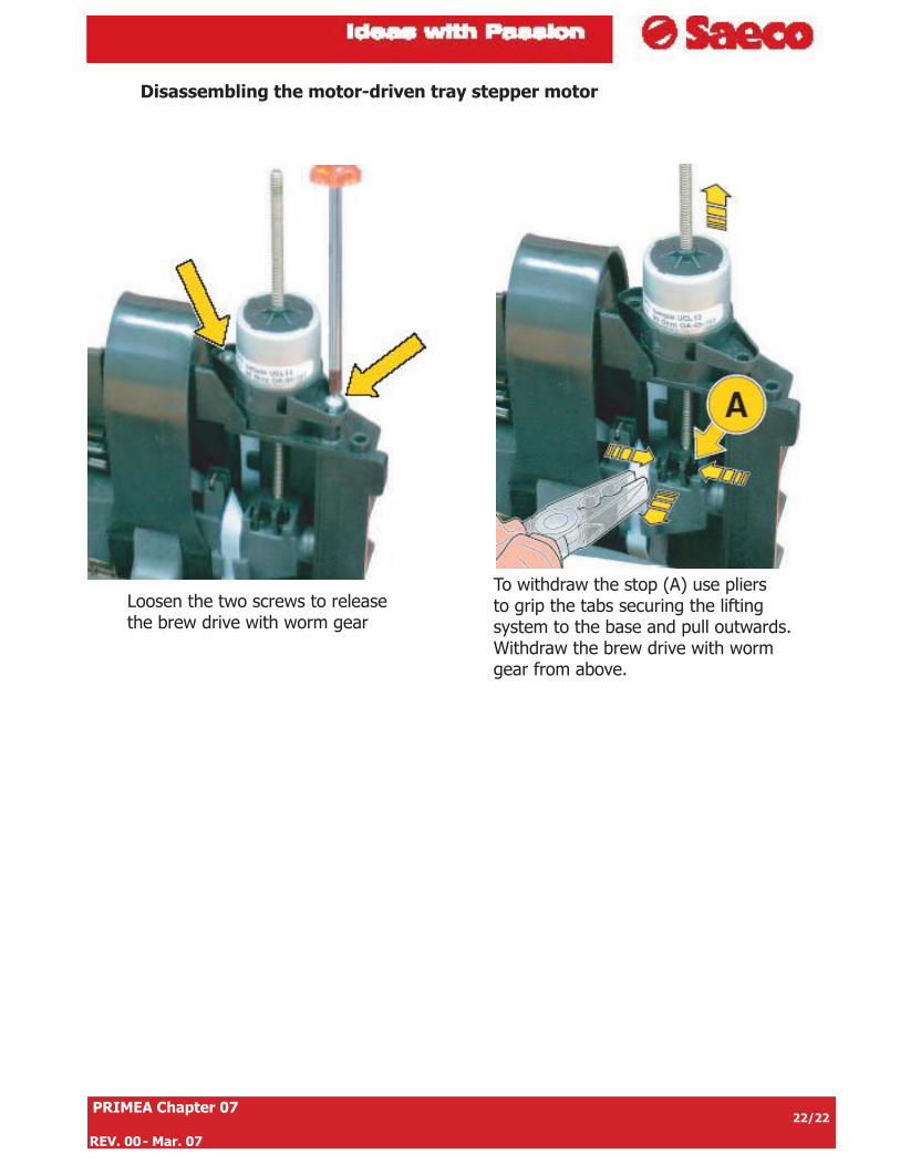
REV. 00 - Mar. 07
Loosen the two screws to release the brew drive with worm gear
To withdraw the stop (A) use pliers to grip the tabs securing the lifting system to the base and pull outwards. Withdraw the brew drive with worm gear from above.
22/22 PRIMEA Chapter 07
Disassembling the motor-driven tray stepper motor

REV. 00 - Mar. 07
CHAPTER 8SERVICE
SCHEDULE
REV.00 PRIMEA 2007 Chapter 08

REV. 00 - Mar. 07
S= ReplacementR= Service P= CleaningD= DescalingC= Inspection*= Number of beverages dispensed
Parts Task Reason Item
Mai
nte
nan
ce
5,0
00
*
10
,00
0*
Casing, tanks, containers, power cable C C C Dirty, damaged see documentation (exploded drawings)
Water coffee andmilk pipesGACO DIM 14 seals S S S WearWater filter S S S Dirty, hygieneSilicon tube C D D Dirty, scale, leaks see documentation (exploded drawings)Turbine C D D Dirty, scale, leaks see documentation (exploded drawings)Boiler C D D Dirty, scale, leaks see documentation (exploded drawings)Multi-valve C D D Dirty, scale, leaks see documentation (exploded drawings)
Boiler valve o-ring S S S Dirty, scale, leaks
Dispensing head P P P Dirty, hygiene see documentation (exploded drawings)Cappuccino valve P P P Dirty, hygiene see documentation (exploded drawings)Grinder BurrsCheck strength of ground coffee
PC
PC
PC
Dirty, hygiene Grain size and dose see documentation (exploded drawings)
Brew unitCleaning C R R Dirty, hygiene Lubrication C R R Dirty, hygiene O-ring C S S Wear see documentation (exploded drawings)Full service C C C Wear Other tasks
Descale C D D Then check condition of parts
Temperature check C C C Client information Explanation of fault C C C Client information Safety check C C C Always Packing C C S Check, always Use new packaging if necessary
8.1 Routine maintenance checklist
PRIMEA 2007 Chapter 081/1

REV. 00 - Mar. 07
CHAPTER 9
AMENDMENTS MADE TO TECHNICAL SERVICE
MANUAL
PRIMEA Chapter 09
REV.00

REV. 00 - Mar. 07
List
of
amen
dmen
ts m
ade
to m
anu
al R
EV.0
0 M
arch
07
DA
TER
EV.
CH
AP
TER
SEC
TIO
NSU
B-S
ECTI
ON
Des
crip
tion
28
/03
02
2.2
Ph
oto
show
ing
milk
tan
k co
mpa
rtm
ent
28
/03
05
5.1
vari
ous
28
/03
05
5.2
5.2
.22
8/0
30
55
.2.3
28
/03
05
5.2
.42
8/0
30
55
.2.5
28
/03
06
6.1
Tou
ch P
lus,
Tou
ch a
nd
Rin
g m
ult
iway
val
ve2
8/0
30
66
.2A
uto
capp
ucc
ino
PRIMEA Chapter 091/1
9.1 Latest amendments