Embed Size (px)
Citation preview

PRIMARY AND SECONDARY SUBSTATIONS PROTECTION AND CONTROL EQUIPMENT
PROT-03-019 Issue No. 15
© SP Power Systems Limited Page 1 of 30
1. SCOPE
This Specification details SP Energy Networks’ requirements for the protection and control equipment to be supplied with indoor 12kV Primary and Secondary switchgear. It also includes requirements for telecontrol and alarm functions.
2. ISSUE RECORD
This is a Reference document. The current version is held on the EN Document Library. It is your responsibility to ensure you work to the current version.
Issue Date Issue No. Author Amendment Details
May 2011 13 Darren Griffin Specifications Prot-03-024 & Prot-03-025 recombined into this specification. Removal of unused types and amalgamation where practicable of remaining types. General editorial changes.
February 2015 14 Darren Griffin/Allan Wales
Panel types reduced to five basic types for inclusion within INS.
February 2020 15 Darren Griffin Document review and minor updates.
3. ISSUE AUTHORITY
Author Owner Issue Authority
Name: Darren Griffin Title: Lead Engineer Engineering Design and Standards
Name: Fraser Shaw Title: Substations Manager Engineering Design and Standards
Name: Fraser Ainslie Title: Head of Engineering Design and Standards
4. REVIEW
This is a Reference document which has a 5 year retention period after which a reminder will be issued to review and extend retention or archive.
5. DISTRIBUTION
This document is not part of a Manual maintained by Document Control and does not have a maintained distribution list.

PRIMARY AND SECONDARY SUBSTATIONS PROTECTION AND CONTROL EQUIPMENT
PROT-03-019 Issue No. 15
© SP Power Systems Limited Page 2 of 30
6. CONTENTS
1. SCOPE ....................................................................................................................................... 1
2. ISSUE RECORD ........................................................................................................................ 1
3. ISSUE AUTHORITY .................................................................................................................. 1
4. REVIEW ..................................................................................................................................... 1
5. DISTRIBUTION .......................................................................................................................... 1
6. CONTENTS ............................................................................................................................... 2
7. REFERENCE AND RELATED DOCUMENTS .......................................................................... 4
8. INTRODUCTION ........................................................................................................................ 4
9. DEFINITIONS ............................................................................................................................ 4
10. GENERAL REQUIREMENTS ................................................................................................... 5
10.1 Equipment Standards................................................................................................... 5
10.2 Equipment Description ................................................................................................ 5
10.3 Performance Requirements ......................................................................................... 5
10.3.1 Reliability ....................................................................................................................... 5 10.3.2 Availability ..................................................................................................................... 5 10.3.3 Maintainability ............................................................................................................... 5 10.3.4 Departures from specification ....................................................................................... 6
11. EQUIPMENT AND SERVICES .................................................................................................. 6
11.1 Common Ratings .......................................................................................................... 6
11.2 Electromagnetic Compatibility .................................................................................... 6
11.3 Testing ........................................................................................................................... 6
11.4 Routine Tests ................................................................................................................ 6
11.5 Quality Requirements................................................................................................... 6
11.6 Quality Assurance ........................................................................................................ 6
11.7 Progress and Inspection Requirements ..................................................................... 6
11.8 Quality Plans/Inspection Checklists ........................................................................... 7
11.9 Inspection and Witnessing of Tests ........................................................................... 7
11.10 Retention of Quality Records ...................................................................................... 7
11.11 Certificate of Conformance ......................................................................................... 7
12. GENERAL .................................................................................................................................. 7
12.1 Equipment Practice ...................................................................................................... 7
12.2 Accommodation ............................................................................................................ 9
13. FUNCTIONAL REQUIREMENTS ............................................................................................ 10
13.1 Restricted Earth Fault ................................................................................................ 10
13.2 Overcurrent/Earth Fault ............................................................................................. 10
13.3 Directional Protection ................................................................................................ 10
13.4 Standby Earth Fault .................................................................................................... 10
13.5 Sensitive Earth Fault .................................................................................................. 10
13.6 Intertripping ................................................................................................................. 11
13.7 Pilot Wire Unit Protection .......................................................................................... 11
13.8 Unit Protection Ring Indication System (Type 1) Primary Substation .................. 11
PRIMARY AND SECONDARY SUBSTATIONS PROTECTION AND CONTROL EQUIPMENT
PROT-03-019 Issue No. 15
© SP Power Systems Limited Page 3 of 30
13.9 Unit Protection Ring Indication System (Type 2) Secondary Substation ............. 12
13.10 Delayed Auto Reclose (DAR) Primary Transformer ................................................ 12
13.11 Feeder Auto Reclose .................................................................................................. 12
13.12 Auto Reclose Protection ............................................................................................ 12
13.13 Two-Stage NVD Protection (33/11kV Primary Transformer Circuits SPD only) ... 14
13.14 Single-Stage NVD Protection .................................................................................... 14
13.15 Circuit Breaker Control .............................................................................................. 15
13.16 Trip Circuit Supervision ............................................................................................. 15
13.17 Voltage Transformers ................................................................................................. 15
13.18 Voltage Transformer Monitoring ............................................................................... 16
13.19 Transformer Auxiliary Tripping Functions .............................................................. 16
13.20 Transformer Auxiliary Alarm Functions ................................................................... 16
13.21 Automatic Load Transfer (Manual Reset) ................................................................ 16
13.22 Automatic Load Transfer (Automatic Reset) ........................................................... 17
13.23 Customer Emergency Trip ......................................................................................... 18
13.24 Customer Intertrip Receive ........................................................................................ 18
13.25 Additional Trip Output ................................................................................................ 18
13.26 Gas Trip ....................................................................................................................... 18
13.27 Gas Alarm .................................................................................................................... 18
13.28 Customer Connection Scheme ................................................................................. 18
13.29 Trip Relays .................................................................................................................. 19
13.30 Statistical Metering ..................................................................................................... 19
13.31 Earth Fault Alarm ........................................................................................................ 20
14. AUXILIARY CONTROL SWITCHES ....................................................................................... 20
15. CURRENT TRANSFORMERS ................................................................................................ 21
15.1 Protection Current Transformers .............................................................................. 21
15.2 Metering Current Transformers ................................................................................ 22
15.3 Control Current Transformers ................................................................................... 22
16. VOLTAGE TRANSFORMERS ................................................................................................ 22
16.1 Standard Voltage Transformer (VT1) ........................................................................ 22
16.2 Dual Primary Ratio Voltage Transformer (VT2) ....................................................... 22
17. SCHEDULE OF EQUIPMENT CONFIGURATIONS ............................................................... 23
17.1 GP111 11/6.6kV Bus Section ..................................................................................... 24
17.2 GP112 11/6.6kV Plain Feeder ..................................................................................... 25
17.3 GP113 11/6.6kV Unit Feeder ...................................................................................... 26
17.4 GP114 11/6.6kV Customer Feeder ............................................................................ 27
17.5 GP115 11/6.6kV Primary Transformer ...................................................................... 29

PRIMARY AND SECONDARY SUBSTATIONS PROTECTION AND CONTROL EQUIPMENT
PROT-03-019 Issue No. 15
© SP Power Systems Limited Page 4 of 30
7. REFERENCE AND RELATED DOCUMENTS
The following standards and other documents are referred to in this Specification in addition to those listed in ENA TS 41-36. The latest version of all documents shall be referenced. IEC 61869-2 Current transformers IEC 61869-3 Inductive voltage transformer IEC 60255-151 Measuring relays and protection equipment IEC 60947-3 Switches, disconnectors, switch disconnectors and fuse-combination units. IEC 61850 Communication networks and systems for power utility automation IEC 62271-100 High-voltage switchgear and control gear – Part 100 high-voltage alternating
current circuit breakers BS 6231 PVC insulated flexible cables for switchgear and control gear wiring ENA TS 48-3 Instantaneous high-impedance differential protection ENA TS 48-4 DC relays associated with a tripping function in protection systems ENA TS 48-5 Environmental test requirements for protection and control equipment and
systems ENA TS 50-18 Application of ancillary electrical equipment ENA TS 50-19 Standard numbering for small wiring (for switchgear and transformers
together with their associated relay panels) ALP 1/* Energy Networks Association conformity assessment list: Protection PROT-15-027 11kV and 6.6kV Protection and Control Settings Guidance INS 50.42.06 Metal enclosed switchgear up to 52kV
8. INTRODUCTION
This Specification details SP Energy Networks’ requirements for the protection and control equipment to be supplied with indoor 12kV Primary and Secondary switchgear. It also includes requirements for telecontrol and alarm functions.
9. DEFINITIONS
For the purpose of this specification, the following definitions shall apply: The Company Refers to SP Distribution plc, SP Transmission plc and SP Manweb plc.
SP Distribution plc. The Distribution Licence Holder for the distribution service area formerly
known as ScottishPower.
SP Transmission plc. The Transmission Licence Holder for the transmission service area formerly known as ScottishPower.
SP Manweb plc The Distribution Licence Holder for the distribution service area formerly known as Manweb.
SP Energy Networks The brand name of the division of ScottishPower Group of Companies that encompasses SP Distribution plc, SP Transmission plc, SP Manweb plc and SP Power Systems Ltd.
The Engineer SP Energy Networks nominated representative having authority over technical matters contained in this specification.
The Tenderer The supplier invited to tender in accordance with this specification.

PRIMARY AND SECONDARY SUBSTATIONS PROTECTION AND CONTROL EQUIPMENT
PROT-03-019 Issue No. 15
© SP Power Systems Limited Page 5 of 30
10. GENERAL REQUIREMENTS
10.1 Equipment Standards
This Specification details the requirements for protection and control equipment to be applied to the 11/6.6kV networks within the SP Distribution plc and SP Manweb plc licence areas. The schedules at the end of this document detail the individual requirements for the most commonly used circuit configurations. As an alternative to the detailed schedules, Tenderers may offer equipment that meets the required functionality and also provides a lower cost option. The Company welcomes innovation and alternatives to traditional designs that still meet the functional requirements of this Specification.
10.2 Equipment Description
This Specification shall be read in conjunction with the following SP Energy Networks and Iberdola INS specifications. PROT-15-027 11kV protection and control application guide INS 50.42.06 Metal enclosed switchgear up to 52kV The equipment shall be suitable for use with indoor switchgear connected to systems having a maximum voltage of 12kV, 3-phase, 50Hz, with the neutral point solidly earthed. The equipment shall be designed to ensure continuity of supply and safety in operation and shall be maintenance free as far as practicable. Particular attention is drawn to the need for adequate ventilation to avoid condensation and build-up of gases in all enclosures. The equipment shall be capable of communicating seamlessly with the Company SCADA system. The equipment shall meet the requirements of the Health and Safety at Work Act 1974, the Electricity at Work Regulations 1989 and the Provision and Use of Work Equipment Regulations 1998.
10.3 Performance Requirements
The equipment design shall be sufficient to meet the following requirements:
10.3.1 Reliability
Where practicable, failure of any component shall not result in an undetected loss of system functions. The Supplier shall protect against multiple and cascading component failures. The mean time between failures (MTBF) of any sub-system component shall be not less than 25,000 hours.
10.3.2 Availability
The Contractor shall include supervisory checks that are required to optimise system availability. Alarms shall be initiated whenever a failure has been detected. The overall substation availability shall be not less than 0.99997.
10.3.3 Maintainability
The contractor shall incorporate all test points, isolation facilities and labelling required to facilitate the maintainability of the system. Recommended maintenance intervals for all supplied equipment shall be stated in the Technical Schedules at the time of tender.

PRIMARY AND SECONDARY SUBSTATIONS PROTECTION AND CONTROL EQUIPMENT
PROT-03-019 Issue No. 15
© SP Power Systems Limited Page 6 of 30
10.3.4 Departures from specification
The Tenderer shall detail departures from the requirements of this Specification.
11. EQUIPMENT AND SERVICES
11.1 Common Ratings
All equipment shall operate satisfactorily within an ambient range of –10ºC to 55ºC. In addition, the equipment shall be able to withstand an ambient temperature range –25ºC to 70ºC during the period of storage and transportation. The equipment shall operate satisfactorily with a relative humidity level of up to 95% at 40ºC. For equipment housed within a substation housing or building, a degree of protection rating of IP50 is required.
11.2 Electromagnetic Compatibility
To ensure compliance with legislation, it is essential that all electrical equipment offered shall meet the current legislation requirements and is marked accordingly. Equipment suppliers shall state the means by which compliance is achieved and supply the associated conformity documentation. In addition, the Contractor shall ensure that electromagnetic compatibility is achieved within the substation, particularly with the increasing application of microprocessor-based equipment.
11.3 Testing
Evidence in the form of type test certificates of proof of performance that the equipment is in accordance with the Specification shall be submitted with the Tender. Energy Networks Association approval notices shall be supplied where applicable.
11.4 Routine Tests
The equipment specified shall be subjected to tests at the manufacturer's works and other tests as agreed. The Company shall specify the range of tests. The Engineer shall be informed at least 21 days before any proposed testing to allow arrangements to be made for factory or site test. Two copies of all test reports shall be supplied to SP Energy Networks.
11.5 Quality Requirements
The Company has a policy of zero defects with its customers and therefore expects support from its suppliers aimed at year on year quality improvement. Analysis of defective items on receipt and in use will be used to assist in subsequent tender analysis.
11.6 Quality Assurance
Manufacturers shall operate a fully documented quality assurance system and should indicate with their tenders the QA Approvals granted to the manufacturer.
11.7 Progress and Inspection Requirements
Access to the Contractor or Sub-Contractor's works shall be granted, at any reasonable time, to allow the Engineer to verify the progress of the work.

PRIMARY AND SECONDARY SUBSTATIONS PROTECTION AND CONTROL EQUIPMENT
PROT-03-019 Issue No. 15
© SP Power Systems Limited Page 7 of 30
11.8 Quality Plans/Inspection Checklists
Prior to the commencement of design/manufacture, the Contractor shall submit to the Company, quality plans/inspection checklists for "mark-up" of the Company's requirements with respect to document approval and quality control activities. Two copies of all approved documents shall be supplied to the Company.
11.9 Inspection and Witnessing of Tests
The Engineer shall carry out, where appropriate, inspections and witness routine tests in accordance with the "mark-up" on the approved quality plans/inspection checklists and agreed test programme. The Contractor shall give seven days’ notice of his intention to carry out any witness points referenced on the quality plans/inspection checklists.
11.10 Retention of Quality Records
The Contractor shall maintain the quality records in an area of safe deposit for a minimum period of 10 years and not dispose of these records without prior agreement of the Company. During the retention period, copies of the quality records shall be made available to the Company on request.
11.11 Certificate of Conformance
The Contractor shall provide a Certificate of Conformance for each item that requires a quality plan/inspection checklist. The Contractor’s nominated representative shall sign this certificate. This document shall reference the quality plan/inspection checklist, the quality records being retained, the Contractor’s unique identification and the Company's order number. One copy of the Certificate of Conformance and, where relevant, the statutory certification shall be despatched with the item and a second copy issued to the Company. A certificate of conformity shall be provided upon completion of each order placed with the successful Tenderer(s). These shall identify the appropriate technical specifications with which the items comply. The certificate shall be sent directly to the nominated Engineer in the enclosed Enquiry documents. The Tenderer shall submit the following documents with the tender:
• Overall quality policy statement
• Copies of any formal quality approvals
• Quality plans for each item offered (these shall identify the control stages during manufacture and test)
12. GENERAL
12.1 Equipment Practice
The equipment supplied shall meet the requirements of ENA TS 48-5, “Environmental test requirements for protection and control equipment and systems” and ENA TS 50-18, “Application of ancillary electrical equipment”. Enclosures shall be of metal construction or other approved material and the thickness of material shall ensure that relays or other equipment do not maloperate due to impact or vibration. The construction shall minimise the spread of fire from any enclosure to a neighbouring enclosure.

PRIMARY AND SECONDARY SUBSTATIONS PROTECTION AND CONTROL EQUIPMENT
PROT-03-019 Issue No. 15
© SP Power Systems Limited Page 8 of 30
Where equipment enclosures are deemed to require anti-condensation heaters and/or switched illumination circuits; then these shall be supplied from a source not exceeding 110V AC in line with ENA TS 50-18 section 3.4.1 to provide safe working conditions. All apparatus and terminals shall be easily accessible without the need to disturb other apparatus or wiring. Each enclosure shall be fitted with a circuit identification label on its front surface. Where rear access is possible, the rear of the enclosure shall also be labelled. If it is possible to remove the enclosure doors or covers, each door/cover shall be individually labelled. All equipment on the exterior of the enclosure shall be labelled to identify its function and, where deemed appropriate by The Engineer, shall be fitted with a warning notice. Labels and inscriptions shall not degrade under the prevailing ambient conditions. The wording and location of all equipment labelling shall be to the satisfaction of The Engineer. The method of attachment and materials used to prevent corrosion shall be to the satisfaction of The Engineer. Enclosures shall be prepared, primed and painted to the satisfaction of The Engineer. Indoor and outdoor enclosures shall be fitted with anti-vermin protection to the satisfaction of The Engineer. The Tenderer shall include details of crimps, crimping systems, wires, terminals and terminations, which they propose to use. Wire colours shall be to the satisfaction of The Engineer. Relay cases shall be earthed using insulated stranded copper cable to BS 6231 type B, with a minimum cross-sectional area of 2.5sq.mm. A maximum of two cables shall be terminated on any single connection. Earth wires shall be green or green/yellow and equipment shall be connected in a radial fashion. The removal of any component shall not affect the integrity of the earthing system. In existing substations, wires are numbered in accordance with BEBS S12 (re-issued as ENA TS 50-19). Where existing substations are to be modified, all new wiring shall also be in accordance with this standard. For new substations, the Tenderer shall provide details of the numbering system he proposes to use but preference shall be given to compliance with ENA TS 50-19. All protection equipment shall be selected from the current issue of the Energy Networks Association approval list - ALP 1/*. In order to comply with IEC 62271-100 for circuit breakers, the cumulative protection and trip relay operating times shall not be less than 10 milliseconds. Feeder fault clearance time, including circuit breaker operation, should not exceed 300ms under normal system operating conditions. The arrangement of equipment on panels shall be subject to approval by The Engineer. The output contacts of protection relays shall be rated to make and break the loads connected without deterioration. The Supplier shall be responsible for providing all auxiliary and tripping relays required to meet the Specification. Trip relays, where required, shall comply with ENA TS 48-4, defined as high or low burden, as required. Protection and ancillary functions may be combined into one or more protective devices to give the most cost-effective arrangement. This arrangement shall be subject to the approval of the Engineer. Time delayed protection shall provide a volt free output contact at an external connection to indicate pick-up of the starting element. Overcurrent and earth fault elements, where no clear indication of the operated element is apparent, shall have separate contacts.

PRIMARY AND SECONDARY SUBSTATIONS PROTECTION AND CONTROL EQUIPMENT
PROT-03-019 Issue No. 15
© SP Power Systems Limited Page 9 of 30
In accordance with ENA TS 41-36, section 2.5.8 the operation of the protection shall be so designed that if the closing and opening releases remain energised simultaneously, the circuit breaker shall not open and close continuously. All protection scheme and circuit breaker operation counters shall be visible when standing in front of the switchgear or associated enclosure. When incorporated into protection relays, they shall be easily accessed by simple navigation of a menu system. Protection Group setting selector switches shall be provided adjacent to the protection equipment, or alternatively this functionality may be provided via relay pushbuttons with suitable indication of status, to enable the protection to be switched from the normal service protection setting to an alternative setting group. The Supplier shall make economic and effective use of the IEC 61850 communication medium and minimise physical wiring between relays, switchgear and any SCADA outstation. Test facilities shall be provided for each protection system to allow independent injection testing of CTs and associated protection relay(s) for each HV circuit breaker. The facilities shall be clearly visible to an operator standing in front of the switchgear. Intertripping and unit protection systems shall be provided with facilities to allow communication and pilot cable isolation for end-to-end testing. The configuration of the test facilities shall be subject to the approval of the Engineer. AC & DC power supply circuits may be protected using miniature circuit breakers in accordance with clause 6.4 and 6.5 of ENA TS 50-18. The circuit-breakers shall be suitable for providing a Point of Isolation in accordance with IEC 60947-3. A lockable cover plate or enclosure shall be provided to prevent circuit-breakers from being closed after they have been opened and padlocked. Isolation links may be of the MC (multi-contact) type or similar.
12.2 Accommodation
Any apparatus, which may require access for testing, maintenance or operational reasons in-situ, shall be accessible from ground level. Protection equipment that can be interrogated using either a front panel display or communications interface shall be positioned at a minimum distance of 450mm to the centre of the equipment from floor. Equipment to which access is required for normal day to day operation, shall not be mounted more than 1.8 metres above any permanent access way. Relays associated with protection and tripping functions shall be visible from the front of the equipment and again, where practicable, be mounted no higher than 1.8 metres above any permanent access way. All indications associated with protection and control equipment shall be visible from the front of the cubicle. All protection and control equipment related to an individual feeder circuit shall, where practicable, be accommodated within the associated circuit breaker auxiliary & control equipment enclosure. Where practicable, this shall include the intertripping relay for that circuit, plus associated intertripping equipment if required. Setting resistors where required shall be accessible to allow adjustment without the need to de-mount. All protection and control equipment related to a transformer incomer circuit shall, where practicable, be accommodated within the associated circuit breaker auxiliary & control equipment enclosure. Automatic voltage control equipment for up to two transformers shall be mounted on a single common panel or wall mounted enclosure as required.

PRIMARY AND SECONDARY SUBSTATIONS PROTECTION AND CONTROL EQUIPMENT
PROT-03-019 Issue No. 15
© SP Power Systems Limited Page 10 of 30
13. FUNCTIONAL REQUIREMENTS
13.1 Restricted Earth Fault
High impedance restricted earth fault to ENA TS 48-3 having a setting range to include 25V - 175V with a maximum step-change of 25V for shunt connected stabilising resistor or 0.05A - 0.5A in 0.01A steps for series connected stabilising resistor. Overvoltage protection and setting resistors shall be provided if required.
13.2 Overcurrent/Earth Fault
Three-phase overcurrent and earth fault protection with IDMT, high set and definite time elements (normal inverse, very inverse and extremely inverse characteristic to IEC 60255-151). When applied to a transformer incomer circuit breaker, should the 11kV circuit breaker fail to trip on an IDMT operation, a Stage 2 overcurrent trip shall be sent to the remote 33kV end after a time delay, settable in the range 0 – 0.5 seconds in 10ms steps. The phase fault setting shall include the range 0.05In - 2.0In. Maximum step-change 0.05In. The earth fault setting shall include the range 0.01In - 1.0In. Maximum step-change 0.05In.
13.3 Directional Protection
Three-phase directional overcurrent with IDMT, and definite time elements (normal inverse, very inverse and extremely inverse characteristic to IEC 60255-151). The phase fault setting shall include the range 0.05In - 2.0In. Maximum step-change 0.05In. Directional earth fault with IDMT and definite time elements (normal inverse, very inverse and extremely inverse characteristic to IEC 60255-151). The earth fault setting shall include the range 0.01In - 1.0In. Maximum step-change 0.05In. To allow full transformer reverse power capability whilst maintaining sensitivity; a load blinding or interlocked directional overcurrent is required.
13.4 Standby Earth Fault
Two-stage standby earth fault with normal inverse, definite time and long-time inverse elements to IEC 60255-151. The current setting range shall include 0.01In - 1.0In. Maximum step-change 0.05In. The time multiplier range shall allow for a 5s and 8s clearance based upon 15% & 20% of the transformer LV current. Stage 1 shall trip the transformer CB. Stage 2 shall trip the transformer CB and initiate an intertrip.
13.5 Sensitive Earth Fault
Sensitive earth fault protection shall include a definite time characteristic. The current setting shall include the range 0.01In - 0.3In. Maximum step-change 0.05In. The time delay setting shall include the range 0 - 20s. Maximum step-change 0.5s.

PRIMARY AND SECONDARY SUBSTATIONS PROTECTION AND CONTROL EQUIPMENT
PROT-03-019 Issue No. 15
© SP Power Systems Limited Page 11 of 30
13.6 Intertripping
Option a: Metallic Pilot Wire Intertripping DC self-supervised intertripping operating over metallic pilot cable, complete with intertrip supply supervision, pilot wire supervision. Output contacts shall be self-reset. Option b: Digital intertripping Digital intertripping operating over C37.94 communication circuits, complete with supervision. Option c: None – hard wired Hard-wired intertripping may be employed where the local and remote ends of the circuit are situated within the same physically secure environment and where a full intertripping scheme is not considered necessary. e.g. Local transformer at a primary substation. Local/remote indication of operation should be included.
13.7 Pilot Wire Unit Protection
Unit protection designed for operation over metallic pilot wires complete with pilot wire supervision and transformer magnetising inrush current detector, capable of interfacing with existing unit and intertripping schemes. A separate instantaneous overcurrent element shall be incorporated to prevent operation other than for system faults. Pilot Wire Supervision - Send Equipment required to inject the unit protection metallic pilot wires with a signal or signals to allow continuous monitoring of the integrity of the pilot wires. The following conditions shall be continuously monitored: 1. Open circuit. 2. Loss of insulation. The pilot wire send end supervision equipment shall be compatible with the receive end equipment. Pilot supervision injection supply voltage shall not exceed 110VAC. Pilot Wire Supervision - Receive Equipment required to continuously monitor and measure a supervision signal or signals in a unit protection metallic pilot wire circuit and alarm for the following conditions: 1. Open circuit. 2. Loss of insulation. The receive equipment shall be compatible with the pilot wire send end supervision equipment.
13.8 Unit Protection Ring Indication System (Type 1) Primary Substation
Ring indication/test circuitry for unit-protected feeders shall incorporate “PILOT FAULTY” and “RING COMPLETE” indication circuits. Separate pilot injection resistors shall be provided. Each resistor shall have a fixed value of 48 Ohms +10%, be continuously rated at 5A and insulated for 230V ac. + 10%. The resistors shall be mounted in suitable fully closed enclosures with adequate ventilation to dissipate heat. The temperature at any point on the unit shall not exceed a value that may be a fire risk. The enclosure shall be provided with a terminal block suitable for making external connections. The unit shall be fitted with a label of
PRIMARY AND SECONDARY SUBSTATIONS PROTECTION AND CONTROL EQUIPMENT
PROT-03-019 Issue No. 15
© SP Power Systems Limited Page 12 of 30
adequate size and legibility with black letters on a red background stating "DANGER TERMINALS LIVE AT 230 VOLTS AC". Provision shall be made for preventing heat from the resistor unit that could cause any deterioration of the resistor, terminal block or internal/external wiring inside the unit. The terminal block for external wiring may be in a separate chamber of the unit and shall be of a size to give safe access for test purposes. Access to the terminal block shall be via a removable cover. Drilling for 2 off conduit entries shall be provided for conduit suitable for accommodating 4 x 2.5mm2 single cables.
13.9 Unit Protection Ring Indication System (Type 2) Secondary Substation
Ring indication/test circuitry for unit-protected feeders shall incorporate “RING COMPLETE” indication circuits.
13.10 Delayed Auto Reclose (DAR) Primary Transformer
The DAR shall: a) Be single shot to lockout.
b) Be initiated by intertrip receive protection operation only unless the intertripping medium is a fault thrower, in this case DAR will be initiated by directional overcurrent operation.
c) Locally detect circuit supply restoration.
d) Reclose the transformer CB after a time delay within the range 0 - 99s (maximum step-change 1.0s), but only if the source end has re-energised the circuit within this time delay.
e) Lockout if the source end is not energised within the reclose time delay.
f) Lockout when the transformer CB trips within the reclaim time following an intertrip receive or any protection trip. The reclaim time shall be settable within the range 0 - 99s (maximum step-change 1.0s). Lockout shall prevent the CB from closing locally via the DAR relay until the relay has been reset.
g) Have the lockout condition resettable on closure of circuit breaker.
h) Be inhibited for a time delay within the range 0 - 60s (maximum step-change 1.0s) after a manual or telecontrol close. The sequence shall then reset.
i) Be provided with an “IN SERVICE/OUT OF SERVICE” selector switch (Section 14).
j) Not inhibit normal circuit protection when the DAR protection is switched “OUT OF SERVICE”.
k) Have an indication “DAR OUT OF SERVICE” clearly visible to a local operator.
13.11 Feeder Auto Reclose
Feeder auto reclose shall include IDMT overcurrent and earth fault and sensitive earth fault protection facilities as previously defined in sections 13.2 and 13.5. In addition, the instantaneous overcurrent and earth fault protection shall have an operation time delay range that includes 0 - 5s. Maximum step-change 30ms.
13.12 Auto Reclose Protection
The scheme shall incorporate local and remote controls to provide DAR in/out and Live Line in/out switching. When switched into live line mode, auto reclose shall be inhibited and any IDMT or definite time protection shall operate instantaneous.
PRIMARY AND SECONDARY SUBSTATIONS PROTECTION AND CONTROL EQUIPMENT
PROT-03-019 Issue No. 15
© SP Power Systems Limited Page 13 of 30
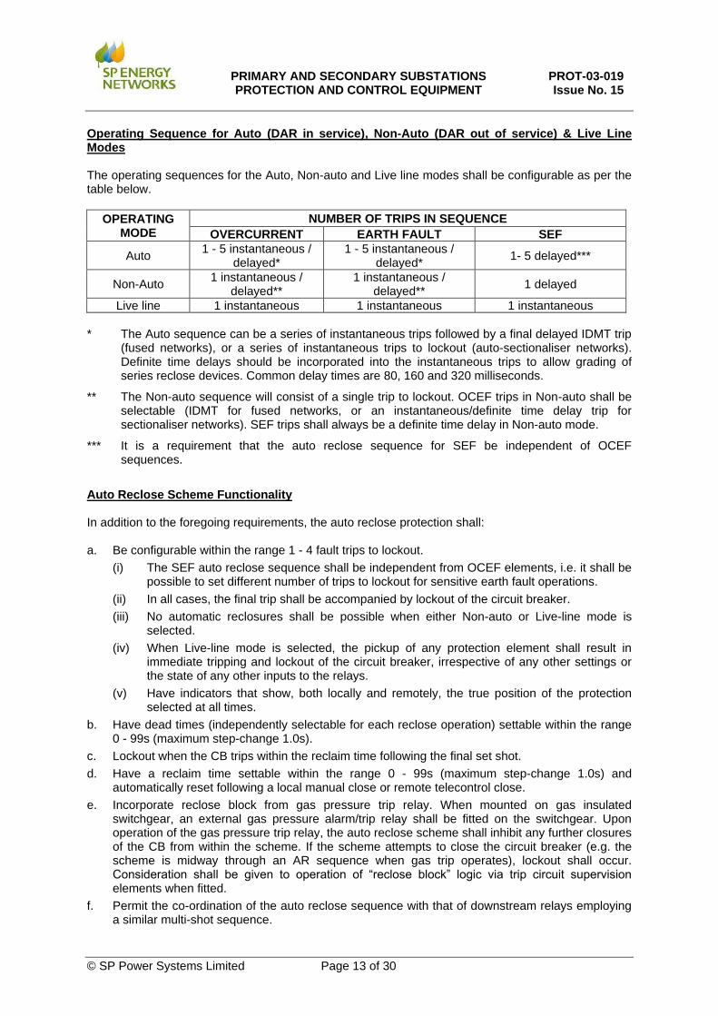
Operating Sequence for Auto (DAR in service), Non-Auto (DAR out of service) & Live Line Modes The operating sequences for the Auto, Non-auto and Live line modes shall be configurable as per the table below.
OPERATING MODE
NUMBER OF TRIPS IN SEQUENCE
OVERCURRENT EARTH FAULT SEF
Auto 1 - 5 instantaneous /
delayed* 1 - 5 instantaneous /
delayed* 1- 5 delayed***
Non-Auto 1 instantaneous /
delayed** 1 instantaneous /
delayed** 1 delayed
Live line 1 instantaneous 1 instantaneous 1 instantaneous
* The Auto sequence can be a series of instantaneous trips followed by a final delayed IDMT trip
(fused networks), or a series of instantaneous trips to lockout (auto-sectionaliser networks). Definite time delays should be incorporated into the instantaneous trips to allow grading of series reclose devices. Common delay times are 80, 160 and 320 milliseconds.
** The Non-auto sequence will consist of a single trip to lockout. OCEF trips in Non-auto shall be selectable (IDMT for fused networks, or an instantaneous/definite time delay trip for sectionaliser networks). SEF trips shall always be a definite time delay in Non-auto mode.
*** It is a requirement that the auto reclose sequence for SEF be independent of OCEF sequences.
Auto Reclose Scheme Functionality In addition to the foregoing requirements, the auto reclose protection shall: a. Be configurable within the range 1 - 4 fault trips to lockout.
(i) The SEF auto reclose sequence shall be independent from OCEF elements, i.e. it shall be possible to set different number of trips to lockout for sensitive earth fault operations.
(ii) In all cases, the final trip shall be accompanied by lockout of the circuit breaker.
(iii) No automatic reclosures shall be possible when either Non-auto or Live-line mode is selected.
(iv) When Live-line mode is selected, the pickup of any protection element shall result in immediate tripping and lockout of the circuit breaker, irrespective of any other settings or the state of any other inputs to the relays.
(v) Have indicators that show, both locally and remotely, the true position of the protection selected at all times.
b. Have dead times (independently selectable for each reclose operation) settable within the range 0 - 99s (maximum step-change 1.0s).
c. Lockout when the CB trips within the reclaim time following the final set shot.
d. Have a reclaim time settable within the range 0 - 99s (maximum step-change 1.0s) and automatically reset following a local manual close or remote telecontrol close.
e. Incorporate reclose block from gas pressure trip relay. When mounted on gas insulated switchgear, an external gas pressure alarm/trip relay shall be fitted on the switchgear. Upon operation of the gas pressure trip relay, the auto reclose scheme shall inhibit any further closures of the CB from within the scheme. If the scheme attempts to close the circuit breaker (e.g. the scheme is midway through an AR sequence when gas trip operates), lockout shall occur. Consideration shall be given to operation of “reclose block” logic via trip circuit supervision elements when fitted.
f. Permit the co-ordination of the auto reclose sequence with that of downstream relays employing a similar multi-shot sequence.
PRIMARY AND SECONDARY SUBSTATIONS PROTECTION AND CONTROL EQUIPMENT
PROT-03-019 Issue No. 15
© SP Power Systems Limited Page 14 of 30
(i) When operating in this mode, instantaneous trips shall be delayed by a selectable time delay and any incident which would have caused tripping but for this time delay shall advance the scheme sequence counter by one and initiate the reclaim timer.
g. The ability to select or deselect sequence co-ordination by SP Energy Networks staff.
h. A standard close pulse time of 0.5 seconds. However, it is preferable for this pulse to be truncated on confirmation of a successful closure of the circuit breaker.
i. Have all variables settable by SP Energy Networks staff.
13.13 Two-Stage NVD Protection (33/11kV Primary Transformer Circuits SPD only)
This protection shall have a minimum of two independent time-delayed stages. The protection shall be capable of operation by input from either capacitive or inductive voltage transformers (typical CVT value is between 25pF and 150pF). It shall have a maximum withstand voltage greater than three times the measuring voltage transformer HV winding phase/phase voltage. The NVD sensitivity shall be variable within the range 0 - 50% of the measuring voltage transformer HV winding phase/phase voltage. Stage 1: Shall trip the 11kV transformer CB after a time delay T1, settable within the range 0 - 10s.
Maximum step-change 0.5s. Stage 2: Shall intertrip to the transformer 33kV power source after a time delay T2, settable within
the range 0 - 20s. Maximum step-change 0.5s. T1 and T2 timing sequences shall run concurrently.
13.14 Single-Stage NVD Protection
SPD This protection shall have one linear time-delay stage. The protection shall be capable of operation by input from either capacitive or inductive voltage transformers (typical CVT value is between 25pF and 150pF). It shall have a maximum withstand voltage greater than three times the measuring voltage transformer HV winding phase/phase voltage. The NVD sensitivity shall be variable within the range 0 - 50% of the measuring voltage transformer HV winding phase/phase voltage. The protection shall trip the 11kV transformer CB after a time delay T1, settable within the range 0 - 10s. Maximum step-change 0.5s. SPM This protection shall have one inverse time delay stage. The protection shall be capable of operation by input from either capacitive or inductive voltage transformers. It shall have a maximum withstand voltage greater than three times the measuring voltage transformer HV winding phase/phase voltage. The NVD sensitivity shall be variable within the range 0 - 50% of the measuring voltage transformer HV winding phase/phase voltage. The protection shall trip the 11kV CB only after an inverse time delay calculated by the following formula. T = 40 Where T = time in seconds and V = Applied Input Voltage V-1 Relay Setting Voltage The relay shall have a time multiplier setting range including 0.125 - 1.0. Maximum step-change 0.125.

PRIMARY AND SECONDARY SUBSTATIONS PROTECTION AND CONTROL EQUIPMENT
PROT-03-019 Issue No. 15
© SP Power Systems Limited Page 15 of 30
13.15 Circuit Breaker Control
Local Closing CB control selector switch set to ‘Standby’ this selection shall disable remote control of the CB from OCC/NMC and enable local control via the circuit breaker control switch (Section 14) or via HMI on the CB. Local circuit breaker closing shall include a variable time delay in the range 0 - 30s, settable by SP Energy Networks staff. Maximum step-change 0.5s. There shall be audio and/or visual indication that the circuit breaker is in the process of closing. It shall be possible to close the circuit breaker to circuit earth after a pre-set time delay via the circuit breaker control switch (Section 14) or HMI. Local Tripping CB control selector switch set to ‘Standby’ this selection shall disable remote control of the CB from OCC/NMC and enable local control via the circuit breaker control switch (Section 14) or via HMI on the CB. Local circuit breaker opening shall include a variable time delay in the range 0 - 30s, settable by SP Energy Networks staff. Maximum step-change 0.5s. There shall be audio and/or visual indication that the circuit breaker is in the process of opening. When closed to circuit earth it shall not be possible to electrically open the circuit breaker. Removal of circuit earth shall be a manual operation. Remote Closing CB control selector switch set to ‘Main’ this selection shall disable local control of the CB from the circuit breaker control switch (Section 14) or HMI and enable control from OCC/NMC. Remote Tripping CB control selector switch set to ‘Main’ this selection shall disable local control of the CB from the circuit breaker control switch (Section 14) or HMI and enable control from OCC/NMC. Sending a telecontrol TRIP command shall not trip the circuit breaker when it is closed in the circuit earth position. Removal of circuit earth shall be a manual operation.
13.16 Trip Circuit Supervision
A scheme which complies with or equivalent to H7 of ER S15, is required. The supervision scheme shall be fail-safe and alarm for any defect in the circuit breaker tripping circuit when the circuit breaker is either open or closed. The alarm shall provide both a local and remote indication. Operation of the trip circuit supervision scheme shall disable circuit breaker closing whilst the circuit breaker is in the normal service position.
13.17 Voltage Transformers
Voltage transformers for protection and metering purposes shall comply with IEC 61869-3, Inductive Voltage Transformers. They shall be of the dry encapsulated type and may be fixed or withdrawable. They shall be in accordance with INS 50.42.06.

PRIMARY AND SECONDARY SUBSTATIONS PROTECTION AND CONTROL EQUIPMENT
PROT-03-019 Issue No. 15
© SP Power Systems Limited Page 16 of 30
They shall be suitable for use on 3-phase, 50Hz, systems having the neutral point solidly earthed and a nominal operating voltage of 11kV or 6.6kV. The equipment shall have a rated voltage of 12kV, a rated insulation level of 75kV and where required have the following configuration:
• Winding 1 shall be for metering
• Winding 2 shall be for protection and control functions
• Winding 3 shall be for auxiliary protection and connected in broken delta to produce a residual voltage
The VT required for each circuit type is listed in the relevant schedules. Metering and protection VT secondary windings (except auxiliary windings) shall be connected in Star configuration. Phase windings a, c and star-point connection shall be protected by fuses or circuit breakers. Phase winding b shall be brought out and terminated on a bolted link connected to earth. The fuses and links shall be mounted in the auxiliary and control equipment enclosure. The auxiliary protection windings shall be connected in broken delta to produce a residual voltage. The two ends of the connection shall be brought out and terminated on links mounted in the auxiliary and control equipment enclosure.
13.18 Voltage Transformer Monitoring
VT monitoring shall be provided to detect the loss of any one or all phases. After a time delay, the relay shall block the operation of any associated directional protection and provide local and remote alarm facility. The time delay shall be user settable within the range of 0 to 30 seconds in 0.5 second steps.
13.19 Transformer Auxiliary Tripping Functions
The following are the minimum externally sourced protections that shall trip the circuit breaker. Operation of these protections shall be individually indicated on site where practicable. a. Buchholz surge.
b. Tap change Buchholz surge.
c. Transformer winding temperature.
d. Transformer pressure relief valve.
13.20 Transformer Auxiliary Alarm Functions
The following are the minimum externally sourced protections shall produce alarms. Where practicable they shall be indicated both locally and remotely at OCC/NMC. a. Buchholz gas.
b. Transformer winding temperature.
c. Tap change alarm.
d. Transformer alarm.
13.21 Automatic Load Transfer (Manual Reset)
Preference shall be given to communication over GOOSE for IEC 61850 systems to reduce wiring and panel complexity. a. Circuit breakers shall be selectable to be either Master or Slave.

PRIMARY AND SECONDARY SUBSTATIONS PROTECTION AND CONTROL EQUIPMENT
PROT-03-019 Issue No. 15
© SP Power Systems Limited Page 17 of 30
b. Only one CB can be selected to be Master at any one time. The remaining CB shall be Slave.
c. The Master CB shall be normally CLOSED.
d. The Slave CB shall be normally OPEN.
e. The load transfer scheme shall normally be IN SERVICE.
f. A loss of supply to the Master CB shall initiate the load transfer operation.
g. The Master CB shall trip after a time delay within the range 0-30s (maximum step-change 0.5s), but only if volts have been confirmed as present on the Slave CB.
h. The Slave CB shall close only after the Master CB is confirmed OPEN.
i. The circuits shall be restored to normal operation by manual switching.
j. On feeder CBs, the load transfer operation shall be inhibited from operation when:
(i) The load transfer scheme is switched OUT OF SERVICE.
(ii) There is no incoming supply on the Slave CB. This check shall be performed PRIOR to opening the Master CB on detection of loss of incoming supply.
(iii) Selected Master CB protections have operated.
(iv) The customer’s emergency trip relay has operated.
(v) The customer’s statutory CB or CBs are open.
13.22 Automatic Load Transfer (Automatic Reset)
a) Circuit breakers shall be selectable to be either Master or Slave.
b) Only one CB can be selected to be Master at any one time. The remaining CB shall be the Slave.
c) The Master CB shall be normally CLOSED.
d) The Slave CB shall be normally OPEN.
e) The automatic load transfer scheme shall normally be IN SERVICE.
f) A loss of supply to the Master CB shall initiate the load transfer operation.
g) The Master CB shall trip after a time delay (T1) within the range 0-30s (maximum step-change 0.5s), but only if volts have been confirmed as present on the Slave CB.
h) The Slave CB shall close after the MASTER CB is confirmed OPEN.
i) The circuits shall be automatically restored to normal operation when the incoming supply is restored to the Master CB.
j) The supply must be continuously available for a period (T2) within the range of 0 - 99s (maximum step change 0.5s) before the Master CB is CLOSED.
k) The Slave CB shall open only after the MASTER CB is confirmed CLOSED.
l) The load transfer scheme shall then reset to automatic operation.
m) On feeder CBs, the automatic load transfer scheme shall be inhibited from operation when:
(i) The load transfer scheme is switched OUT OF SERVICE.
(ii) There is no incoming supply on the Slave CB. This check shall be performed PRIOR to opening the Master CB on detection of loss of incoming supply.
(iii) Selected Master CB protections have tripped the breaker.
(iv) The customer’s emergency trip relay has operated.
(v) The customer’s statutory CB or CBs are open.

PRIMARY AND SECONDARY SUBSTATIONS PROTECTION AND CONTROL EQUIPMENT
PROT-03-019 Issue No. 15
© SP Power Systems Limited Page 18 of 30
13.23 Customer Emergency Trip
Customer emergency trip protection may be provided by a trip relay which complies with ENA TS 48-4, defined as high/low burden as required or via suitable binary inputs on a protection device. The emergency trip shall have trip and alarm contacts, plus local indication. Where the emergency trip pushbutton is located outside of the confines of the SP Energy Networks substation (i.e. customer premises), then the trip voltage shall be supplied from the customer battery system. Indication shall be hand reset. Circuit breaker closing shall not be allowed until the emergency trip relay has been reset.
13.24 Customer Intertrip Receive
Customer intertrip receive protection shall have trip and alarm contacts plus local indication. Indication shall be hand reset. Circuit breaker closing shall not be allowed until the customer intertrip receive relay has been reset. This protection shall be supplied from the customer battery system and operate over pilot wires.
13.25 Additional Trip Output
A volt-free trip output contact (minimum rating 110Vdc 5Adc for 3s) operated by the overcurrent/earth fault relay and wired to a panel mounted terminal block shall be provided to provide an intertripping facility to the local transformer ACB.
13.26 Gas Trip
Circuit breakers with gas as a breaking medium shall incorporate a trip contact that will operate when the gas density drops below the stated circuit breaker safe service operating level. Operation of this contact shall trip the circuit breaker and, where intertrip protection is connected, intertrip the remote circuit ends. Circuit breaker closing shall be disabled until this contact can be reset.
13.27 Gas Alarm
Circuit breakers with gas as an insulating medium shall incorporate an alarm contact that will operate at a set pressure level between the minimum safe operating pressure and the normal filling pressure. Operation of this contact shall operate an alarm both locally and remotely.
13.28 Customer Connection Scheme
This connection type is intended primarily, but not exclusively, for 11kV generation connections. The protection requirements comprise unit protection (SP Energy Networks provide a set of class x CTs to allow the customer to provide a connections protection between the customer assets and the SP Energy Networks point of connection); backup protection (IDMT overcurrent and earth fault); G98/G99 protection (backup to that provided by the Customer and time-delayed by a further 0.5s). Further details of the G98/G99 and connections protections are given below. G98/G99 Protection Over/Under Voltage This shall measure the phase to star point voltage in all three phases and operate if the measured voltage in any one phase is outside the applied setting. A two-stage element shall be provided in each case, with a setting range of between 10% to 110% (under-voltage) and 60% to 150% (over-voltage) of nominal voltage, with a step size of 1%. It shall be possible to apply a definite time delay of 0 to 100 seconds to each element, with a step size of 0.5 seconds.

PRIMARY AND SECONDARY SUBSTATIONS PROTECTION AND CONTROL EQUIPMENT
PROT-03-019 Issue No. 15
© SP Power Systems Limited Page 19 of 30
It shall be possible to apply dead pole logic to the UV element. This may utilise under-voltage and current detectors to determine whether the circuit breaker has opened to isolate the voltage transformer. Operation of the dead pole logic shall block the UV element. Over/Under Frequency This shall measure the three-phase frequency and operate if the measured frequency is between 51Hz - 53Hz or 46Hz to 48Hz with a step size of 0.01Hz. It shall be possible to apply a definite time delay of 0 to 100 seconds to each element, with a step size of 0.5 seconds. Rate of Change of Frequency (ROCOF) This shall measure the frequency in all three phases and operate if the measured rate of change in all three phases is outside the applied setting. A single-stage element shall be provided in each case, with a setting range of between 0.1 to 10 Hz/second, with a step size of 0.01 Hz. It shall be possible to apply a definite time delay of 0 to 100 seconds to each element, with a step size of 0.5 seconds. (During any applied time delay, the element shall continue to measure the ROCOF to determine whether the applied setting has been exceeded). It shall be possible to apply dead pole logic to the ROCOF element. This may utilise under-voltage and current detectors to determine whether the circuit breaker has opened to isolate the voltage transformer. Operation of the dead pole logic shall block the ROCOF element. Connections Protection A high-impedance current differential protection shall be provided by the third-party at the interface between SP Energy Networks and any third-party connection. The protection shall meet the requirements of ENA TS 48-3 and shall utilise a differential algorithm based on current inputs from each end of the protected plant. The protection shall be capable of simultaneously detecting all phase to phase and phase to earth faults. Under credible system operating conditions, the operating time of the protection (excluding trip relays), shall not exceed 30ms at three times setting.
13.29 Trip Relays
Trip relays, where required, shall comply with ENA TS 48-4, defined as high/low burden as required. Where electrically reset relays are employed, a means shall be provided to prevent the energisation of the reset coil whilst the trip initiation is still standing.
13.30 Statistical Metering
The following values shall be displayed locally per circuit:
• MW • MVAr • Volts
• Amps • Hz
The following remote analogue values shall be made available to SCADA as required:
• MW • MVAr • Volts
• Amps
• Hz
• %Vnps • %Inps

PRIMARY AND SECONDARY SUBSTATIONS PROTECTION AND CONTROL EQUIPMENT
PROT-03-019 Issue No. 15
© SP Power Systems Limited Page 20 of 30
13.31 Earth Fault Alarm
A two-stage earth fault alarm element operated from a current transformer located in the 11kV neutral earth connection. The relay shall have a DTL characteristic in accordance with IEC 60255-151 with a setting range between 5% and 100%. The above relay shall have self-monitoring circuits, with a watchdog arranged to give an alarm on failure and may be capable of remote communication. Relays used shall provide comprehensive fault and event recording facilities.
14. AUXILIARY CONTROL SWITCHES
All switches shall preferably, with engineer’s approval, be included within appropriate protection devices. All switches accommodated in this manner shall have clear indications as to the state with select before operate checks against inadvertent operation. SW1 3-position labelled “Circuit Breaker Control” Position 1 “Trip” Biased OFF in central position Position 2 “Neutral” Padlockable in the biased OFF position Position 3 “Close” Pistol grip handle Interlocked to prevent inadvertent operation SW2 2-position labelled “Control Selector Switch” Position1 “Standby” Padlockable in both positions Position 2 “Main” Lozenge type handle SW3 2-position labelled “Protection Setting Group Selection” Position 1 “Setting Group 2” Padlockable in both positions Position 2 “Normal” Lozenge type handle SW4 2-position labelled “DAR” Position 1 “Out of Service” Position 2 “In Service” SW5 2-position labelled “Live Line” Position 1 “Live Line” Padlockable in all positions Position 2 “Normal” Lozenge type handle SW6 2-position labelled “Auto Load Transfer” Position 1 “Out of Service” Padlockable in both positions Position 2 “In Service” Lozenge type handle SW7 2-position labelled “Auto Load Transfer CB Selection” Position 1 “Slave” Padlockable in both positions Position 2 “Master” Lozenge type handle

PRIMARY AND SECONDARY SUBSTATIONS PROTECTION AND CONTROL EQUIPMENT
PROT-03-019 Issue No. 15
© SP Power Systems Limited Page 21 of 30
15. CURRENT TRANSFORMERS
15.1 Protection Current Transformers
Current transformers shall comply with IEC 61869-2
Function
Rated Continuous
Thermal Current A
Rated Secondary Current A
Turns Ratio CT Ratio
Minimum Knee Point
Voltage V
Max Secondary Resistance
Ohms
Max Excitation
Current A
Rating & Class
Icth Isn Ek Rct Ie
CT2.1 Main /
Backup 1250 1
1:600:1200 1200/1 20Rct + 300 15 0.03 X
1:600:1200 600/1 20Rct + 150 7.5 0.06 X
CT2.2 Unit 2000 2.89
1:415:692 2000/1200/2.89 19Rct + 75 1.5 0.06 X
1:415:692 2000/1200/2.89 32Rct + 75 1.0 0.06 X
CT2.3 Main /
Backup/ Unit
630 1
1:300:600 600/1 20Rct + 320 9.0 0.06 X
1:300:600 300/1 20Rct + 160 4.5 0.12 X
CT2.4 Unit 630 1 1:400 400/1 33Rct + 200 6.0 0.08 X
CT2.5 * REF 1250 1
1:600:1200 1200/1 20Rct + 300 15 0.03 X
1:600:1200 600/1 20Rct + 150 7.5 0.06 X
CT2.6 SBEF 2000 1 1:2000 2000/1 - - - 15VA, 5P10
CT2.7 SBEF 1250 1 1:300:600:
1200 1200/600/300/1 - - -
15VA, 5P10
CT2.8 * Main /
Backup/ REF
2000 1 1:2000 2000/1 12Rct + 240 20.0 0.03 X
Note 1 Rated primary current is defined as the rated current of the associated switchgear.
Note 2 The rated short time thermal current withstand rating of all protection CT’s is defined as the rated short time withstand current of the associated switchgear.
* Supplied as part of a set of 4 matched CTs when used for primary transformer REF protection
PRIMARY AND SECONDARY SUBSTATIONS PROTECTION AND CONTROL EQUIPMENT
PROT-03-019 Issue No. 15
© SP Power Systems Limited Page 22 of 30
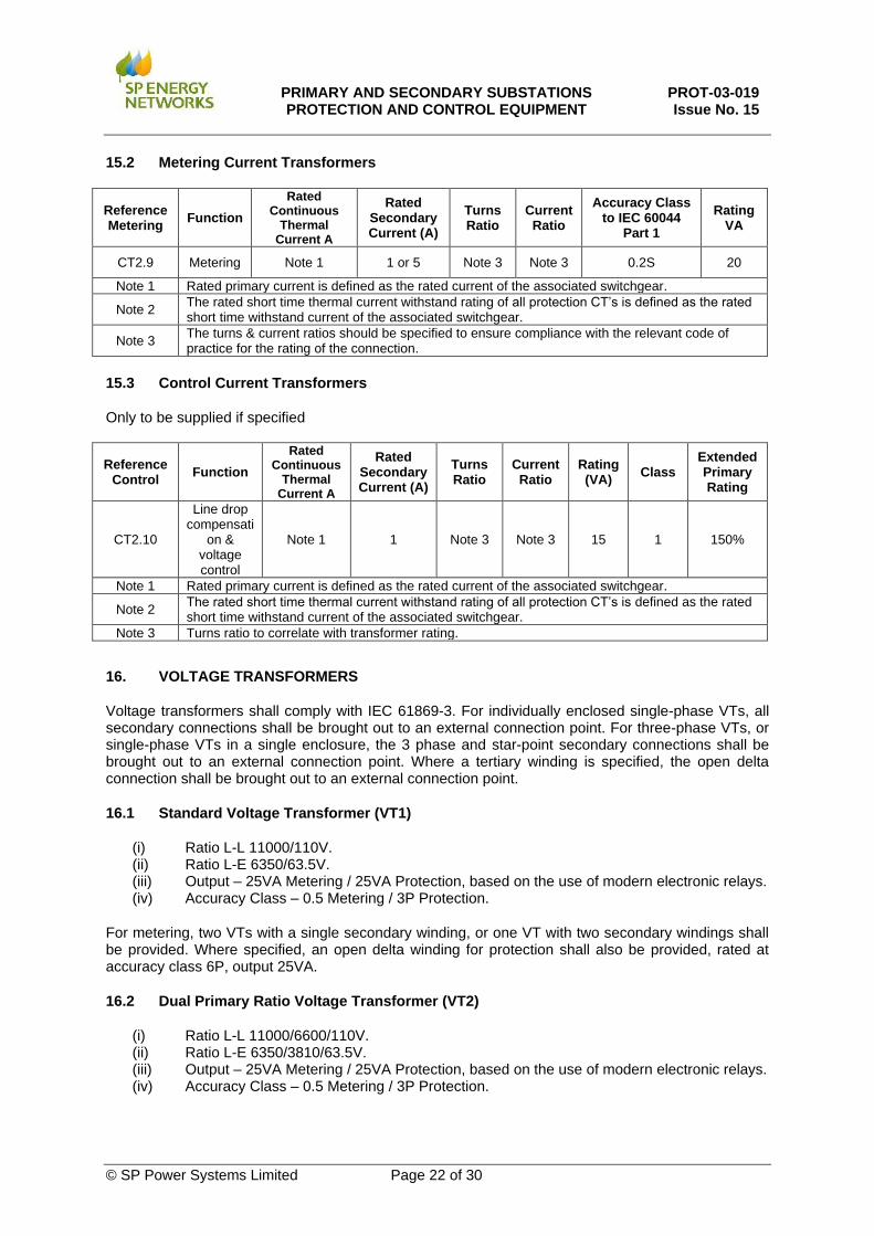
15.2 Metering Current Transformers
Reference Metering
Function
Rated Continuous
Thermal Current A
Rated Secondary Current (A)
Turns Ratio
Current Ratio
Accuracy Class to IEC 60044
Part 1
Rating VA
CT2.9 Metering Note 1 1 or 5 Note 3 Note 3 0.2S 20
Note 1 Rated primary current is defined as the rated current of the associated switchgear.
Note 2 The rated short time thermal current withstand rating of all protection CT’s is defined as the rated short time withstand current of the associated switchgear.
Note 3 The turns & current ratios should be specified to ensure compliance with the relevant code of practice for the rating of the connection.
15.3 Control Current Transformers
Only to be supplied if specified
Reference Control
Function
Rated Continuous
Thermal Current A
Rated Secondary Current (A)
Turns Ratio
Current Ratio
Rating (VA)
Class Extended Primary Rating
CT2.10
Line drop compensati
on & voltage control
Note 1 1 Note 3 Note 3 15 1 150%
Note 1 Rated primary current is defined as the rated current of the associated switchgear.
Note 2 The rated short time thermal current withstand rating of all protection CT’s is defined as the rated short time withstand current of the associated switchgear.
Note 3 Turns ratio to correlate with transformer rating.
16. VOLTAGE TRANSFORMERS
Voltage transformers shall comply with IEC 61869-3. For individually enclosed single-phase VTs, all secondary connections shall be brought out to an external connection point. For three-phase VTs, or single-phase VTs in a single enclosure, the 3 phase and star-point secondary connections shall be brought out to an external connection point. Where a tertiary winding is specified, the open delta connection shall be brought out to an external connection point.
16.1 Standard Voltage Transformer (VT1)
(i) Ratio L-L 11000/110V. (ii) Ratio L-E 6350/63.5V. (iii) Output – 25VA Metering / 25VA Protection, based on the use of modern electronic relays. (iv) Accuracy Class – 0.5 Metering / 3P Protection.
For metering, two VTs with a single secondary winding, or one VT with two secondary windings shall be provided. Where specified, an open delta winding for protection shall also be provided, rated at accuracy class 6P, output 25VA.
16.2 Dual Primary Ratio Voltage Transformer (VT2)
(i) Ratio L-L 11000/6600/110V. (ii) Ratio L-E 6350/3810/63.5V. (iii) Output – 25VA Metering / 25VA Protection, based on the use of modern electronic relays. (iv) Accuracy Class – 0.5 Metering / 3P Protection.
PRIMARY AND SECONDARY SUBSTATIONS PROTECTION AND CONTROL EQUIPMENT
PROT-03-019 Issue No. 15
© SP Power Systems Limited Page 23 of 30
If dual primary ratio VTs are not available, then 2 x single primary ratio VTs shall be supplied in readiness for voltage upgrade. For metering, two VTs with a single secondary winding, or one VT with two secondary windings shall be provided. Where specified, an open delta winding for protection shall also be provided, rated at accuracy class 6P, output 25VA.
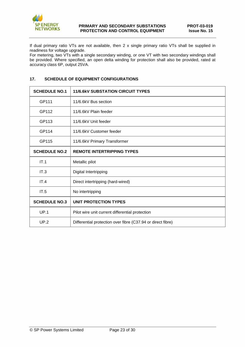
17. SCHEDULE OF EQUIPMENT CONFIGURATIONS
SCHEDULE NO.1 11/6.6kV SUBSTATION CIRCUIT TYPES
GP111 11/6.6kV Bus section
GP112 11/6.6kV Plain feeder
GP113 11/6.6kV Unit feeder
GP114 11/6.6kV Customer feeder
GP115 11/6.6kV Primary Transformer
SCHEDULE NO.2 REMOTE INTERTRIPPING TYPES
IT.1 Metallic pilot
IT.3 Digital Intertripping
IT.4 Direct intertripping (hard-wired)
IT.5 No intertripping
SCHEDULE NO.3 UNIT PROTECTION TYPES
UP.1 Pilot wire unit current differential protection
UP.2 Differential protection over fibre (C37.94 or direct fibre)
PRIMARY AND SECONDARY SUBSTATIONS PROTECTION AND CONTROL EQUIPMENT
PROT-03-019 Issue No. 15
© SP Power Systems Limited Page 24 of 30
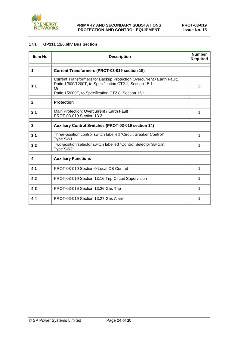
17.1 GP111 11/6.6kV Bus Section
Item No Description Number Required
1 Current Transformers (PROT-03-019 section 15)
1.1
Current Transformers for Backup Protection Overcurrent / Earth Fault, Ratio 1/600/1200T, to Specification CT2.1, Section 15.1. Or Ratio 1/2000T, to Specification CT2.8, Section 15.1.
3
2 Protection
2.1 Main Protection: Overcurrent / Earth Fault PROT-03-019 Section 13.2
1
3 Auxiliary Control Switches (PROT-03-019 section 14)
3.1 Three-position control switch labelled “Circuit Breaker Control” Type SW1
1
3.2 Two-position selector switch labelled "Control Selector Switch". Type SW2
1
4 Auxiliary Functions
4.1 PROT-03-019 Section 0 Local CB Control 1
4.2 PROT-03-019 Section 13.16 Trip Circuit Supervision 1
4.3 PROT-03-019 Section 13.26 Gas Trip 1
4.4 PROT-03-019 Section 13.27 Gas Alarm 1

PRIMARY AND SECONDARY SUBSTATIONS PROTECTION AND CONTROL EQUIPMENT
PROT-03-019 Issue No. 15
© SP Power Systems Limited Page 25 of 30
17.2 GP112 11/6.6kV Plain Feeder
Item No Description Number Required
1 Current Transformers (PROT-03-019 section 15)
1.1 Current Transformers for Main Protection: Overcurrent / Earth Fault, Ratio 1/300/600T, to Specification CT2.3, Section 15.1.
3
2 Protection
2.1 Main Protection: Overcurrent / Earth Fault PROT-03-019 Section 13.2
1
2.2 Sensitive Earth Fault Protection PROT-03-019 Section 13.5
1
2.3 Feeder Auto Reclose PROT-03-019 Section 13.11 & Section 13.12
1
3 Auxiliary Control Switches (PROT-03-019 section 14)
3.1 Three-position control switch labelled “Circuit Breaker Control” Type SW1
1
3.2 Two-position selector switch labelled "Control Selector Switch" Type SW2
1
3.3 Two-position selector switch labelled “Protection Setting Group Selection” Type SW3
1
3.4 Two-position selector labelled “DAR” Type SW4
1
3.5 Two-position selector labelled “Live Line” Type SW5
1
4 Auxiliary Functions
4.1 PROT-03-019 Section 0 Local CB Control 1
4.2 PROT-03-019 Section 13.16 Trip Circuit Supervision 1
4.3 PROT-03-019 Section 13.26 Gas Trip 1
4.4 PROT-03-019 Section 13.27 Gas Alarm 1
PRIMARY AND SECONDARY SUBSTATIONS PROTECTION AND CONTROL EQUIPMENT
PROT-03-019 Issue No. 15
© SP Power Systems Limited Page 26 of 30
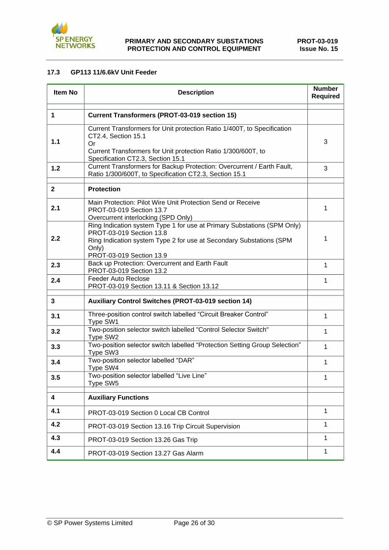
17.3 GP113 11/6.6kV Unit Feeder
Item No Description Number Required
1 Current Transformers (PROT-03-019 section 15)
1.1
Current Transformers for Unit protection Ratio 1/400T, to Specification CT2.4, Section 15.1 Or Current Transformers for Unit protection Ratio 1/300/600T, to Specification CT2.3, Section 15.1
3
1.2 Current Transformers for Backup Protection: Overcurrent / Earth Fault, Ratio 1/300/600T, to Specification CT2.3, Section 15.1
3
2 Protection
2.1 Main Protection: Pilot Wire Unit Protection Send or Receive PROT-03-019 Section 13.7 Overcurrent interlocking (SPD Only)
1
2.2
Ring Indication system Type 1 for use at Primary Substations (SPM Only) PROT-03-019 Section 13.8 Ring Indication system Type 2 for use at Secondary Substations (SPM Only) PROT-03-019 Section 13.9
1
2.3 Back up Protection: Overcurrent and Earth Fault PROT-03-019 Section 13.2
1
2.4 Feeder Auto Reclose PROT-03-019 Section 13.11 & Section 13.12
1
3 Auxiliary Control Switches (PROT-03-019 section 14)
3.1 Three-position control switch labelled “Circuit Breaker Control” Type SW1
1
3.2 Two-position selector switch labelled "Control Selector Switch" Type SW2
1
3.3 Two-position selector switch labelled “Protection Setting Group Selection” Type SW3
1
3.4 Two-position selector labelled “DAR” Type SW4
1
3.5 Two-position selector labelled “Live Line” Type SW5
1
4 Auxiliary Functions
4.1 PROT-03-019 Section 0 Local CB Control 1
4.2 PROT-03-019 Section 13.16 Trip Circuit Supervision 1
4.3 PROT-03-019 Section 13.26 Gas Trip 1
4.4 PROT-03-019 Section 13.27 Gas Alarm 1
PRIMARY AND SECONDARY SUBSTATIONS PROTECTION AND CONTROL EQUIPMENT
PROT-03-019 Issue No. 15
© SP Power Systems Limited Page 27 of 30
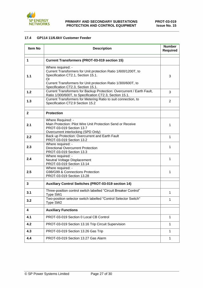
17.4 GP114 11/6.6kV Customer Feeder
Item No Description Number Required
1 Current Transformers (PROT-03-019 section 15)
1.1
Where required: - Current Transformers for Unit protection Ratio 1/600/1200T, to Specification CT2.1, Section 15.1. Or Current Transformers for Unit protection Ratio 1/300/600T, to Specification CT2.3, Section 15.1.
3
1.2 Current Transformers for Backup Protection: Overcurrent / Earth Fault, Ratio 1/300/600T, to Specification CT2.3, Section 15.1.
3
1.3 Current Transformers for Metering Ratio to suit connection, to Specification CT2.9 Section 15.2
2
2 Protection
2.1
Where Required: - Main Protection: Pilot Wire Unit Protection Send or Receive PROT-03-019 Section 13.7 Overcurrent interlocking (SPD Only)
1
2.2 Back up Protection: Overcurrent and Earth Fault PROT-03-019 Section 13.2
1
2.3 Where required: - Directional Overcurrent Protection PROT-03-019 Section 13.3
1
2.4 Where required: - Neutral Voltage Displacement PROT-03-019 Section 13.14
1
2.5 Where required: - G98/G99 & Connections Protection PROT-03-019 Section 13.28
1
3 Auxiliary Control Switches (PROT-03-019 section 14)
3.1 Three-position control switch labelled “Circuit Breaker Control” Type SW1
1
3.2 Two-position selector switch labelled "Control Selector Switch" Type SW2
1
4 Auxiliary Functions
4.1 PROT-03-019 Section 0 Local CB Control 1
4.2 PROT-03-019 Section 13.16 Trip Circuit Supervision 1
4.3 PROT-03-019 Section 13.26 Gas Trip 1
4.4 PROT-03-019 Section 13.27 Gas Alarm 1

PRIMARY AND SECONDARY SUBSTATIONS PROTECTION AND CONTROL EQUIPMENT
PROT-03-019 Issue No. 15
© SP Power Systems Limited Page 28 of 30
Item No Description Number Required
Auxiliary Functions continued
4.5 PROT-03-019 Section 13.23 Customer Emergency Trip 1
4.6 PROT-03-019 Section 13.24 Customer Intertrip Receive 1
4.7 PROT-03-019 Section 13.18 VT Monitoring 1
5 Voltage Transformer (PROT-03-019 section 16)
5.1 Single (VT1) or Dual primary (VT2) voltage ratio as required, with two secondary windings and one auxiliary winding.
3

PRIMARY AND SECONDARY SUBSTATIONS PROTECTION AND CONTROL EQUIPMENT
PROT-03-019 Issue No. 15
© SP Power Systems Limited Page 29 of 30
17.5 GP115 11/6.6kV Primary Transformer
Item No Description Number Required
1 Current Transformers (PROT-03-019 section 15)
1.1 Where required: - Current Transformers for 33kV Unit Protection, Ratio 2.89/1200/2000T (connected in Delta), to Specification CT2.2, Section 15.1.
3
1.2
Current Transformers for Restricted Earth Fault and Directional Overcurrent, Ratio 1/600/1200T, to Specification CT2.1, Section 15.1. Or Ratio 1/2000T, to Specification CT2.8, Section 15.1.
4
1.3 Where required: - Current Transformers for Line Drop Compensation to Specification CT2.10, Section 15.3.
1
1.4
Current Transformer for Standby Earth Fault, Ratio 1/2000T, 15VA, 5P10 to Specification CT2.6, Section 15.1. Or Ratio 1/300/600/1200T, 15 VA, 5P10 to Specification CT2.7, Section 15.1.
1
2 Protection
2.1 Main Protection: Restricted Earth Fault PROT-03-019 Section 13.1
1
2.2 Back up Protection: Overcurrent/Earth Fault PROT-03-019 Section 13.2
1
2.3 Directional Overcurrent PROT-03-019 Section 13.3
1
2.4
2 Stage Standby Earth Fault (SPD) PROT-03-019 Section 13.4 Single Stage Standby Earth Fault/Earth Fault Alarm PROT-03-019 Section 13.4 & 13.31
1
2.5 Intertripping PROT-03-019 Section 13.6 option a, b or c
1
2.6 Where required: - Delayed Auto Reclose: PROT-03-019 Section 13.10
1
2.7 2 stage Neutral Voltage Displacement (SPD only) PROT-03-019 Section 13.13
1
3 Auxiliary Control Switches (PROT-03-019 section 14)
3.1 Three-position control switch labelled “Circuit Breaker Control” Type SW1
1
3.2 Two-position selector switch labelled "Control Selector Switch" Type SW2
1
3.3 Where required: - Two-position selector switch labelled “DAR” Type SW4
1

PRIMARY AND SECONDARY SUBSTATIONS PROTECTION AND CONTROL EQUIPMENT
PROT-03-019 Issue No. 15
© SP Power Systems Limited Page 30 of 30
Item No Description Number Required
4 Auxiliary Functions
4.1 PROT-03-019 Section 0 Local CB Control 1
4.2 PROT-03-019 Section 13.16 Trip Circuit Supervision 1
4.3 PROT-03-019 Section 13.26 Gas Trip 1
4.4 PROT-03-019 Section 13.27 Gas Alarm 1
4.5 PROT-03-019 Section 13.18 VT Monitoring 1
4.6 PROT-03-019 Section 13.19 Transformer Auxiliary Tripping Functions 1
4.7 PROT-03-019 Section 13.20 Transformer Auxiliary Alarm Functions 1
4.8 PROT-03-019 Section 13.29 Mechanical Protection Trip Relay 1
4.9 PROT-03-019 Section 13.30 Statistical Metering 1
5 Voltage Transformer (PROT-03-019 section 16)
5.1 Single (VT1) or Dual (VT2) primary voltage ratio as required, with one secondary winding.
3