Embed Size (px)
Citation preview


We have presented how a wormhole attack can be done on BSR. In this paper we focus on the wormhole attacks on one of the geographic routing protocol named Boundary State Routing Protocol (BSR)[2]. In these attacks two malicious nodes tunnel traffic from one end of the network to the other end using an out-band link. Their main goal is to attract traffic to drop, alter or simply, look at the packets later on. Due to he characteristics of the wormhole attacks, cryptographic solutions are not sufficient. Numerous physical approaches have been proposed to secure the neighbor discovery process. We also presented a novel solution using two schemes: Reverse Routing Scheme (RRS) and Authentication of Nodes Scheme (ANS).
Also we have proposed two schemes for the detection and obviously prevention of the wormhole attack on BSR [1].
This paper is divided into total of six sections. Section 1 consists of introduction, Problem statement and problem definition. Section 2 describes the basics of Routing and vulnerability found in today’s Adhoc networks. Section 3 is the security issues in wireless Adhoc networks followed by previous work done on wormhole attack in next section. Section- 5 is about BSR and its working. Section 6 consists of approach and methodology for detecting and evading wormhole. and section 8 gives simulation results of our proposed system. Section 9 concludes with the conclusion and future work.
II. ROUTING A .Basics Of Routing: The wireless nature of communication and lack of any security infrastructure raises several security problems. Ad hoc network research has resulted in a number of routing protocols suitable for use in MANETs [15]. Most current research in MANET routing is focused on topology-based protocols. Topology based routing protocols use the information about links that exist in the network to perform packet forwarding and are generally classified as either table-driven or on-demand.Research has shown that position-based routing protocols or Geographic routing protocols or location aware networks are a good alternative to on-demand protocols in many cases [16, 17]. B.Geographic Routing Position-based routing protocols use node's geographical position to make routing decisions, resulting in improved efficiency and performance. These protocols require that a node be able to obtain its own geographical position and the geographical position of the destination. Generally, this information is obtained via Global Positioning System (GPS) and location services.GPS provides physical location information for routing. This information is then maintained within a centralized or distributed location database. Geographic routing protocols use this location information to progressively forward packets through the physical space toward the destination location, with intermediate next-hop routing decisions based on selecting the neighbor that has the closest distance, compass setting, or some other measure of forward progress toward the destination [7], [8], [9], [10], [11]. This approach to routing has the advantage of eliminating the need for nodes to maintain conventional routing information. Geographic forwarding offers a near-stateless, low-overhead, and low-latency solution to routing in ad hoc networks. A geographic routing protocol called Boundary State Routing (BSR). BSR relies upon an improved forwarding strategy called Greedy-Bounded- Compass forwarding. C.Boundary State Routing (BSR)
BSR is implemented using the combination of Greedy Bounded Compass forwarding and the Boundary Mapping. Greedy Bounded Compass Forwarding
In BSR protocol, Failure of geographic forwarding due to local minima only arises on void boundaries and the outer boundary. Previous research by Karp [3] investigated the probing of boundaries to accumulate the link state information in boundary nodes. Boundary State Routing (BSR) relies upon Greedy-Bounded-Compass forwarding [2]. Compass forwarding [11] selects the neighbor on the closest angle to the destination.
In Greedy-Bounded-Compass forwarding strategy, initially source sends a packet to the next node by using Greedy forwarding. On Greedy failure, the location is recorded as the closest ever location, and the packet switches to Bounded Compass mode. When the packet is routed through Bounded Compass mode, the packet can only revert to the Greedy mode if a next-hop location is available, which is closer to the destination than the closest ever location. If the next hop is farther from the destination, the algorithm checks for an alternate Boundary route. If successful, the Boundary route is used in preference to the Bounded Compass route, as the choice is informed by the optimal direction around the boundary.
E.Poornima et al. / International Journal on Computer Science and Engineering (IJCSE)
ISSN : 0975-3397 Vol. 3 No. 1 Jan 2011 360

Fig.1 Greedy-Bounded Compass Routing
III.WORMHOLE ATTACK ANALYSIS
A wormhole is an attack on the routing protocol of a Mobile Ad-hoc Network (MANET). Wormhole attack is also known as tunneling attack. A tunneling attack is where two or more nodes may collaborate to encapsulate and exchange messages between them along existing data routes. In a wormhole attack, an attacker receives packets at one point in the network, “tunnels” them to another point in the network, and then replays them into the network from that point. In general, wormhole attacks consists two malicious nodes tunneling traffic from one end of the network to the other For tunneled distances longer than the normal wireless transmission range of a single hop, it is simple for the attacker to make the tunneled packet arrive with better metric than a normal multihop route, for example through use of a single long-range directional wireless link [12] or through a direct wired link to a colluding attacker. It is also possible for the attacker to forward each bit over the wormhole directly, without waiting for an entire packet to be received before beginning to tunnel the bits of the packet, in order to minimize delay introduced by the wormhole. Due to the nature of wireless transmission, the attacker can create a wormhole even for packets not addressed to itself, since it can overhear them in wireless transmission and tunnel them to the colluding attacker at the opposite end of the wormhole. If the attacker performs this tunneling honestly and reliably, no harm is done; the attacker actually provides a useful service in connecting the network more efficiently. However, the wormhole puts the attacker in a very powerful position relative to other nodes in the network, and the attacker could exploit this position in a variety of ways. The attack can also still be performed even if the network communication provides confidentiality and authenticity, and even if the attacker has no cryptographic keys. Furthermore, the attacker is invisible at higher layers; unlike a malicious node in a routing protocol, which can often easily be named, the presence of the wormhole and the two colluding attackers at either endpoint of the wormhole are not visible in the route. The wormhole attack is particularly dangerous against many ad hoc network routing protocols in which the nodes that hear a packet transmission directly from some node consider themselves to be in range of (and thus a neighbor of) that node. A. Placement of wormhole colluder nodes: The placement of compromised nodes to launch a wormhole attack plays an important role in the effectiveness of a wormhole. Below we present some scenarios where a wormhole attack cannot be launched or cannot persist. We present scenarios where three colluder nodes launch a self-contained in-band wormhole attack. In this paper, we assume that the attacker has the ability to bypass the routing algorithm at all three attacking nodes. Consider the scenario where nodes ln1 and ln2 are the attacker nodes. Nodes ln1 and ln2 act as the wormhole tunnel endpoints. Nodes ln1 and ln2 attract network traffic by sending false advertisement of being neighbors and attempt to send the attracted traffic between one another. Nodes A, B, C, D, E, and F are uncompromised nodes and thus are mislead by the incorrect routing advertisement of the link between nodes ln1 and ln2. When node B receives a packet from node A to be destined for node F, node finds the shortest path to node F via the link between nodes ln1and ln2, and thus forwards the packet to ln1, making the wormhole attack fall victim to its own success.
An attacker can be placed in BSR in two ways. One of the possible ways is that one of the attackers is present in the route to the destination.
E.Poornima et al. / International Journal on Computer Science and Engineering (IJCSE)
ISSN : 0975-3397 Vol. 3 No. 1 Jan 2011 361

Fig 2. Wormhole attack by node in the route
As shown in Figure 2, the node that is present in the route that is established in accordance with BSR, can direct the packets to the other intruder that direct the data to the destination.
The other possibility is by the movement of the node to the route by overhearing the data packets and processing them for routing information.
Fig 3 Wormhole Attack by the movement of the node.
As shown in figure 3, the intruder node can move to a better position so that the packets can be routed through it as per BSR protocol.
IV. PROPOSED SOLUTION In [1], we proposed two methodologies to detect and prevent the attacks mentioned above. The first method is the Reverse Route Scheme (RRS). In RRS, the attack by an intermediate node is detected and avoided. The second one is the Authentication of Nodes Scheme (ANS). In ANS, the attack shown in figure 3 can be detected and avoided.
A. Reverse Route Scheme (RRS):
The first type of attack is detected using RRS scheme. In RRS we use two terminologies, Witness_value and Witness_threshold and Honest Node The ad-hoc network consists of honest and malicious nodes. These nodes may be placed at arbitrary geographical locations. Nodes become candidates for geographic routing depending on their geographic location. Routing paths consist of sequences of nodes. Each node on the routing path is responsible for forwarding the message towards the geographic destination. In RRS, the source routes the packet to the destination node, the destination node tries to reach the source node in the reverse path..The reverse path is the path through which the data is traversed from destination node to source node. Here the destination node sends a packet called data_acknowledegment packet, for the data it has received, to the source node. The data_acknowledgement packet is sent to the next node that is closer to the Source and it is forwarded to the next nodes in reverse greedy forwarding method. If greedy forwarding fails, then Bounded Compass method is used. After receiving the data_acknowledgement packet, the source node checks for the route in the packet. The source node estimates the route from it to the destination according to the locations of the nodes in the network. If the estimated route is in deviation with the route in the packet, the source node comes to know the intrusion action. Definition-1 (Witness_value) A Witness_value is defined as the number of nodes in the forward route matching with the nodes in the reverse route.
Definition-2(Witness_threshold) A Witness_threshold is defined as the minimum number of nodes in the forward route that should match with the nodes in the reverse route.
Definition-3 (Honest Node) An honest node knows its correct geographical location, follows the maximum range constraint and executes routing protocol correctly. Otherwise, the node is called malicious node or faulty node.
The format of data_acknowledgement packet in RRS method is as follows:
E.Poornima et al. / International Journal on Computer Science and Engineering (IJCSE)
ISSN : 0975-3397 Vol. 3 No. 1 Jan 2011 362

Data Source
Node-id
Destination
Node-id
Route from
Source to dest
Route from Dest toSource
Figure for Data Acknowlegement Packet in RRS method The first field specifies the data packet received from source, second field specifies node id of the source, next field specifies about destination node id,the next field describes the forward route from source to destination, And the Last field describes the Backward route form destination to source. Let us consider the Routing procedure in ‘Greedy Forwarding’.In the above figure 3, A is the source node and F is the destination node. In1 and In2 are the intruders performing ‘worm hole attack’.In ‘Greedy Forwarding’, source node A calculates the distance between its neighbor nodes and the destination node F. For example we take G, H,L are the other neighbor nodes than B to A. Then A calculates the distances BF, GF, HF, LF. It finds the minimum of these and sends data to the corresponding neighbor node. If BF is the smallest among BF, GF, HF and LF, A sends the data to B. In RRS, we introduce the concept of ‘Backward routing’. When the data from A reaches F, F also tries to reach A through a reverse route. For this, F generates a packet called ‘data_acknowledgement’ and sends it to A using Greedy Forwarding. Here the data_acknowledge packet contains the forward route through which the data has reached the destination. The source node upon receiving the data_acknowledge, compares the nodes in the forward route and the reverse route. The number of witnesses is taken and compared to the witness_threshold. If the witness_value is less than the witness_threshold, the source shifts to another route rather than the first forwarded route. B. Authentication of Nodes Scheme (ANS):
The second type of attack, shown in figure 3 is detected using this scheme. This type of attack cannot be detected by ordinary methods as the intruders move to the locations such that the traffic is automatically diverted towards them. To avoid this type of attack, verification of authentication details of the nodes in the route is done at the destination node. Here it is assumed that the nodes in the network share their certificates and digital signatures. In the data packet that is routed through the intermediate node, the node adds its digital signature. All the intermediate nodes must add their digital signatures in the data packet that travelled through it. The
E.Poornima et al. / International Journal on Computer Science and Engineering (IJCSE)
ISSN : 0975-3397 Vol. 3 No. 1 Jan 2011 363
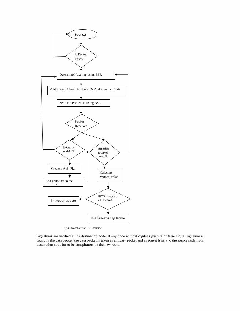
Fig.4 Flowchart for RRS scheme
Signatures are verified at the destination node. If any node without digital signature or false digital signature is found in the data packet, the data packet is taken as untrusty packet and a request is sent to the source node from destination node for to be conspirators, in the new route.
If(Packet
Ready
Source
Determine Next hop using BSR
Add Route Column to Header & Add id to the Route
Send the Packet ‘P’ using BSR
Packet Received
If(Currnt node!=Dn
If(packet received=Ack_Pkt
Create a Ack_Pkt
Add node-id’s in the te l
Calculate Witnes_value
If(Witness_value<Threhold Intruder action
Use Pre-existing Route
E.Poornima et al. / International Journal on Computer Science and Engineering (IJCSE)
ISSN : 0975-3397 Vol. 3 No. 1 Jan 2011 364

TABLE 1. ALGORITHM FOR ANS SCHEME
At Source ‘S’ If (any packet P to be sent) { Add ‘route’ column to hdr; Add ‘Signatures’ column to hdr; Add id to ‘route’; Add digital signature to ‘Signatures’; Send the packet P using BSR; } If ( received a packet ) { If ( received packet == data_acknowledge ){ Note the ‘Signatures’ in the hdr; Note the other route noted in the hdr; Verify the signatures; If ( verification successful) Discard the route noted; Else Drop the packet; Repeat the procedure for next packet; } } At intermediate node ‘I’ If ( received a packet P ) { If ( I am not the destination ) { Add id to ‘route’ in hdr; Add signature to ‘Signatures’ in hdr; Forward P using BSR; } } At destination ‘D’ If ( received a packet P ) { Note the route in hdr; Note the ‘Signatures’ in hdr; Verify the signatures; If ( verification successful ) noted route = null; Else noted route unchanged; Generate data acknowledge packet; Add the noted route in data_acknowledge; Add ‘route’ column to hdr; Add ‘Signatures’ column to hdr; Add id to ‘route’; Add signature to ‘Signatures’; Forward the data_acknowledge to source node ‘S’ using BSR; }
V ANALYSIS OF THE PROPOSED SCHEMES
The RRS scheme is discussed first and ANS later.
In RRS, let a source node S sent data packet using BSR to a destination D. Let the data packet has traversed through the route S-A-G-H-I-J-L-D. The destination node after receiving the data packet creates a data_acknowledgement packet and records the route in it. The destination sends the data_acknowledgement packet in reverse path to source S, using BSR again. The source node S upon receiving the data_acknowledgement, records the reverse route through which the data_acknowledgement has traversed. Let the reverse route be D-L-M-I-H-O-S. Here, the matching nodes are H, I and L. Hence the witness_value is 3. If the witness_threshold is less than 3, the forward route is accepted and data is sent through it. Else, the source node forwards the next data through other possible route.
E.Poornima et al. / International Journal on Computer Science and Engineering (IJCSE)
ISSN : 0975-3397 Vol. 3 No. 1 Jan 2011 365

Let us consider a malicious node in the forward route as in the first case shown in figure 2. The malicious node forwards the data to another malicious node in the network that is closer to the destination. Here, the forward route is varied from the original route. Hence there would be less witness_value. Since the witness_value is less, the source node shifts to another route avoiding the malicious node. Thus using RRS, we can achieve secured routing of the data packets.
Now consider the ANS scheme. In ANS scheme, we assume that the node’s certificate and the secret session keys are generated by strong cryptosystems. Each node that forwards the data signs the packet with its secret key or MAC (Message Authentication Code). Let an adverse node ‘M1’ that moved to a position such that the data from source ‘S’ to destination ‘D’, should be forwarded through it according to BSR protocol. If the node M1 accepts and drops the data packets, by RRS scheme, the source S comes to know about the attack. If the node M1 passes the data to another intruder in the network, RRS scheme detects it. The only possible attack is that M1 can modify the data in the packet and forward. Let the route through which the data is forwarded be S-A-B-M1-C-D. When the data is received by A, it adds its digital signature to the header of the packet. As shown in figure 4, the node B verifies the signature of the node A and adds its signature to the packet. The node M1 cannot add its signature to the packet and hence either repeats the signatures of other nodes or forwards as it is. The destination D verifies the signatures of the intermediate nodes in the packet it has received. If any fault in the signatures is found, the destination asks the source to repeat the packet through other possible route, using data_acknowledge packet.
data S D S-A-B-M1-C
h(A)h(B)h(R)h(C)
Fig 4. Packet format used by ANS scheme
The source node resends the untrusty packet through other possible route to the destination. By comparing the two data packets, the destination decides the untrusty route and sends the information about it to the source node through data_acknowledge. The source node discards the route and informs its neighbors about the malicious node M1. Thus, a malicious node can be avoided from routing in BSR, using ANS scheme.
VI MATHEMATICAL PROOF
Let G = (V, E) be graph containing a pair of V vertices and E edges respectively.According to BSR protocol, a source node ms that wants to send data to a destination node md, it adds a header as shown below:
data Source node Destination node
Next neighbor node
Mode of Forwarding
Last visited Concave node
Fig.5 for Header of a message packet
msg_pkt = {data, ms, md, mnx, forward_mode, mconcave }
The first field in the header is the message or data tobe sent,second field specifies the source node-,ms,the next field is the destination node- md, mnx is the node to which data packet is to be forwarded. mnx is decided by the mode of forwarding that is noted as forward_mode. Two modes of forwarding are allowed in BSR protocol.The packet is to be routed through any one of the Mode. The forwarding mode may be either GREEDY_FORWARDING or BOUNDED COMPASS_FORWARDING.Initally Mode of forwarding is set to GREEDY_FORWARDING,if it fails to route then it is set to BOUNDED COMPASS FORWARDING. mconcave is the last concave node that the packet has reached.
The GREEDY_FORWARDING follows a method as mnx = mj where mj satisfies = min ( ,
, … , )
= the distance between the nodes mj and md. and mj is
the neighbor node of the current node mc.
The BOUNDED COMPASS FORWARDING selects the neighbor to forward data as mnx = mj where mj satisfies
E.Poornima et al. / International Journal on Computer Science and Engineering (IJCSE)
ISSN : 0975-3397 Vol. 3 No. 1 Jan 2011 366

Ɵ(mjmcmd)=min(Ɵ(mj1mcmd), Ɵ(mj2mcmd), ..,Ɵ(mjimcmd) )
Ɵ(mjmcmd) is the angle made by the line mjmc with mcmd The attacker ma bluffs the mc so that either is
the minimum or Ɵ(mamcmd) as per the forwarding_mode. The attacker may forward the data to another node by altering mnx and mean while read or alter the data in the packet. The method of attack is mentioned in section III.
The RRS scheme modifies the header to
msg_pkt = { data, ms, md, mnx, [ms, m1, m2, …, mc], forward_mode, mconcave, rn }
data_acknowledge = { data_acknowledge, md, ms, mnx, [ms, m1, m2, …, md], [ md, mi1, mi2, … mc], forward_mode, mconcave , rn}
The data_acknowledge is sent back to the source node repeating the sequence number rn of the data packet in the data_acknowledge packet through the reverse route. The source node sends the following packets through other possible routes until an optimum route is formed between source node and destination node as stated in theory.
The chance of attack on both the forward route and reverse route is very less and hence and optimized route is less vulnerable to attacks. The method also helps for the two-way communication between the source node and destination node making some of the services easier.
The ANS scheme modifies the header as:
msg_pkt = {data, ms, md, mnx, [ms, m1, m2, …, mc], [Sms, Sm1, Sm2, …, Smc], forward_mode, mconcave, rn }
Both the destination node and the intermediate nodes verify the signatures in the packet. The signature generation and distribution is done by different methodologies [7]. If any fault in the signatures in the packet is considered as the malicious packet and asked for the repetition of the packet through another possible route.
The data_acknowledge can be sent as data_acknowledge = { data_acknowledge, md, ms, mnx, [ms, m1, m2, …, md], [Sms,
Sm1, Sm2, …, Smc], [ md, mi1, mi2, … mc], [Smd, Smi1, Smi2, …,
Smc], forward_mode, mconcave , rn }
VII.SIMULATION RESULTS A. Simulation Set-up
The simulation parameters are listed in Table 3. For our simulations, we use CBR (Constant Bit Rate) application, UDP/IP, IEEE 802.11b MAC and physical channel based on statistical propagation model. Random waypoint model [18] is used for scenarios with node mobility. The minimum speed for the simulations is 0 m/s while the maximum speed is 10 m/s. A traffic generator was developed to simulate constant bit rate source. Duration of the simulations is 900 seconds. The network efficiency is measured for the basic BSR routing protocol and BSR with theWAP method. To evaluate the schemes we have simulated the schemes in NS2. NS2 (Network Simulator) is an IEEE standardized simulator for simulating network functions.
Examined Protocol BSR Simulation Time 20ms Simulation Area 1500x1500 Number of nodes 14,25,50,100 Transmission range 250m Traffic type cbr Payload size 512 Malicious nodes 2,3 No of worm holes 2
E.Poornima et al. / International Journal on Computer Science and Engineering (IJCSE)
ISSN : 0975-3397 Vol. 3 No. 1 Jan 2011 367

B.PERFORMANCE METRICS
The number of attackers in the network is varied as 5% of the number of nodes in the network. The number of sources is varied as 10% of the number of nodes in the network. A total number of 1000 packets are transmitted into the network to analyze the performance. Here we are using two performance parameters to evaluate the schemes:
1. Detection Ratio 2. Misleaded packet
DETECTION RATIO:-Detection Ratio can be defined as the ratio of number of attackers detected by the scheme to the actual number of attackers in the network. For example for simulation purpose, if we have added four intruders into the network and executed the scheme, if it detects two intruders, the detection ratio will be 50%.
MISLEADED PACKETS:- For detecting the intruder, initial transmission of packets is mandatory. So the source node keeps on sending the packets to a particular link until it recognizes the intrusion. Here if some intrusion is detected in a particular route through which the source is already sending the data, the source node can change the route and send the remaining data. But the previously sent data is a mere wastage. These data packets are termed as misleaded packets.
We calculated the number of misleaded packets and Detection Ratio is presented in a graph.
C.SIMULATION RESULTS:
The result for the ‘Misleaded packets’
Fig.6 No of packets sent through Malicious Nodes
Here the graph is clearly showing that the number of misleaded packets in BSR is more because of no security feature implemented. As BSR_RRS and BSR_ANS detect the intruders, the intruders can be avoided and the data can be sent through a secured link. The graph also shows that BSR_ANS scheme achieves very less number of misleaded packets.
The result for the Detection Ratio
E.Poornima et al. / International Journal on Computer Science and Engineering (IJCSE)
ISSN : 0975-3397 Vol. 3 No. 1 Jan 2011 368

Fig 7. Ratio of No. of attackers detected vs No of attackers
Here intrusion detection cannot be done by BSR. So its detection ratio will be zero. Also in BSR-RRS scheme, we try to avoid the intrusion action but in fact intrusion detections will not be there. The performance of BSR-RRS avoiding the intrusions can be seen in figure 2, where BSR-RRS achieves lesser number of misleaded packets. BSR-ANS perfectly detects the intrusion and hence its detection ratio is at maximum level.
VIII CONCLUSION
The Geographic routing mechanism has been presented in this paper. The possible attacks on the BSR protocol have been discussed. The detection of such attacks is difficult and is of course very much important.
In this paper, two schemes have been presented to detect and avoid the types of attacks mentioned in section III. The proposed schemes achieve higher detection ratio and detection accuracy. The RRS method uses no other methodologies to detect the intrusion. The malfunctioning of the intermediate nodes can be easily detected by RRS. The ANS method uses the cryptographic principles for the security of the data packets.
The witness_threshold is one of the threshold values considered as a standard value here. But it should be decided and varied according to the density of the network. This we left as a future scope of this paper. In ANS, the distribution of certificates is assumed done before. It is also could be concentrated, to avoid attacks on the exchange of certificates.
REFERENCES
[1] E. Poornima, C. Shobha Bindu, S.K. Munwar,"Detection and Prevention of Layer-3 Wormhole Attacks on Boundary State Routing in Ad Hoc Networks," ace, pp.48-53, 2010 International Conference on Advances in Computer Engineering, 2010,Avaliable at ieeexplore.ieee.org/xpls/abs_all.jsp?arnumber=5532875
[2] Colin J. Lemmon and Phillip Musumeci, “Boundary Mapping and Boundary State Routing (BSR) in Ad Hoc Networks”, IEEE TRANSACTIONS ON MOBILE COMPUTING, VOL. 7, NO. 1, JANUARY 2008
[3] Luis Fernando Garcia and Jean-Marc Robert Preventing Layer-3 Wormhole Attacks in Ad-hoc Networks with Multipath DSR B. Karp, Geographic Routing for Wireless Networks. Harvard Univ., 2000.
[4] M. Heissenbüttel and T. Braun, “A Novel Position-Based and Beacon-Less Routing Algorithm for Mobile Ad-Hoc Networks,” Proc. Third IEEE Workshop Applications and Services in Wireless Networks (ASWN' 03), pp. 197-209, 2003.
[5] Shree Murthy , J. J. Garcia-Luna-Aceves, An efficient routing protocol for wireless networks, Mobile Networks and Applications, v.1 n.2, p.183-197, Oct. 1996
[6] T.-W. Chen and M. Gerla, “Global State Routing: A New Routing Scheme for Ad Hoc Wireless Networks,” Proc. IEEE Int'l Conf. Comm. (ICC '98), pp. 171-175,1998.
[7] J.C. Navas and T. Imielinski, “GeoCast—Geographic Addressing and Routing,” Proc. ACM MobiCom, pp. 66-76, 1997. [8] T. Imielinski and J.C. Navas, GPS-Based Addressing and Routing, IETF RFC 2009, Dept. of Computer Science, Rutgers Univ., 1996. [9] T. Camp, Location Information Services in Mobile Ad Hoc Networks.Colorado School of Mines, Oct. 2003. [10] R. Nelson and L. Kleinrock, “The Spatial Capacity of a Slotted ALOHA Multihop Packet Radio Network with Capture,” IEEE Trans.
Comm., vol. 3, pp. 684-694, June 1984. [11] H. Takagi and L. Kleinrock, “Optimal Transmission Ranges for Randomly Distributed Packet Radio Terminals,” IEEE Trans. Comm.,
vol. 32, pp. 246-257, Mar. 1984. [12] T.-C. Hou and V.O.K. Li, “Transmission Range Control in Multihop Packet Radio Networks,” IEEE Trans. Comm., vol. 34,pp. 38-44,
Jan. 1986. [13] G. Finn, “Routing and Addressing Problems in Large Metropolitan-Scale Internetworks,” Technical Report ISI/RR-87-180, ISI,1987. [14] E. Kranakis, H. Singh, and J. Urrutia, “Compass Routing on Geometric Networks,” Proc. 11th Canadian Conf. Computational
Geometry (CCCG ’99), 1999. [15] E. Royer and C-K. Toh, A Review of Current Routing Protocols for Ad-Hoc Mobile Wireless Networks. IEEE Personal
Communications Magazine, April 1999, 46-55. [16] Y. Ko, and N. Vaidya, Location Aided Routing in Mobile AdHoc Networks, Proceedings of the 4th International Conference on
Mobile Computing and Networking, Dallas, USA, 1998.
E.Poornima et al. / International Journal on Computer Science and Engineering (IJCSE)
ISSN : 0975-3397 Vol. 3 No. 1 Jan 2011 369

[17] R. Morris and D. De Couto, Location Proxies and Intermediate Node Forwarding for Practical Geographic Forwarding, Technical Report MIT-LCS-TR-824, MIT Laboratory for Computer Science, June 2001.
AUTHORS INFORMATION
E.Poornima received her B.Tech Degree in Computer Science and Engineering from Jawaharlal Lal Nehru Technological University, Hyderabad, India in 2004. She is currently pursuing her M.Tech in Computer Science at Jawaharlal Lal Nehru Technological University college of Engineering, Anantapur, A.P., India. Her Current Research Interest includes Network Security and Wireless CommunicationSystems
C. Shoba Bindu received her B.Tech Degree in Electronics & Comm. Engineering from Jawahar Lal Nehru Technological University college of Engineering, Anantapur, India, in 1997; M.Tech in Computer Science & Engineering from Jawahar Lal Nehru Technological University college of Engineering , Anantapur, India, in 2002. She is currently pursuing her Ph.D in Computer Science at Jawahar Lal Nehru Technological University college of Engineering, Anantapur, A.P., India. Her Current Research Interest includes Network Security and Wireless Communication System
E.Poornima et al. / International Journal on Computer Science and Engineering (IJCSE)
ISSN : 0975-3397 Vol. 3 No. 1 Jan 2011 370


![MLSR: a novel routing algorithm for multilayered satellite ... · a distributed routing protocol. The routing protocol presented in [11] uses a hybrid approach that uses geographic-based](https://img.dokumen.tips/doc/110x75/5f75ea15ac54b849b71c1cdc/mlsr-a-novel-routing-algorithm-for-multilayered-satellite-a-distributed-routing.jpg)