Embed Size (px)
Citation preview
Prevention of a Simulated Aerosol Can Explosion With a Mixture of Halon 1301 and Nitrogen November 2008 DOT/FAA/AR-TN08/49
This document is available to the U.S. public through the National Technical Information Service (NTIS), Springfield, Virginia 22161.
U.S. Department of Transportation Federal Aviation Administration
ote
tech
nica
l not
e te
chni
ca
NOTICE This document is disseminated under the sponsorship of the U.S. Department of Transportation in the interest of information exchange. The United States Government assumes no liability for the contents or use thereof. The United States Government does not endorse products or manufacturers. Trade or manufacturer's names appear herein solely because they are considered essential to the objective of this report. This document does not constitute FAA certification policy. Consult your local FAA aircraft certification office as to its use. This report is available at the Federal Aviation Administration William J. Hughes Technical Center’s Full-Text Technical Reports page: actlibrary.act.faa.gov in Adobe Acrobat portable document format (PDF).
Technical Report Documentation Page 1. Report No. DOT/FAA/AR-TN08/49
2. Government Accession No. 3. Recipient's Catalog No.
4. Title and Subtitle PREVENTION OF A SIMULATED AEROSOL CAN EXPLOSION WITH A MIXTURE OF HALON 1301 AND NITROGEN
5. Report Date November 2008
6. Performing Organization Code
7. Author(s) John W. Reinhardt and Robert Penman, III
8. Performing Organization Report No.
9. Performing Organization Name and Address Federal Aviation Administration
10. Work Unit No. (TRAIS)
William J. Hughes Technical Center Airport and Aircraft Safety Research and Development Division Fire Safety Branch Atlantic City International Airport, NJ 08405
11. Contract or Grant No.
12. Sponsoring Agency Name and Address U.S. Department of Transportation Federal Aviation Administration Air Traffic Organization Operations Planning Office of Aviation Research and Development Washington, DC 20591
13. Type of Report and Period Covered Technical Note
14. Sponsoring Agency Code ANM-110
15. Supplementary Notes 16. Abstract
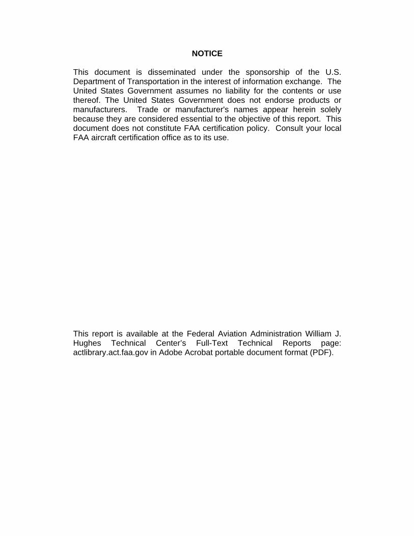
This research was conducted to determine if a combination of Halon 1301 and nitrogen gas would prevent an aerosol can explosion. The aerosol can explosion simulation tests were conducted in the Pressure Fire Modeling Facility, at the Federal Aviation Administration William J. Hughes Technical Center, Atlantic City International Airport, New Jersey. The aerosol can explosion simulator, used for the Aircraft Cargo Compartment Minimum Performance Standard, was mounted inside the instrumented pressure vessel that was located in this facility. The Halon 1301 and nitrogen were introduced to the pressure vessel using two different commercial off-the-shelf systems. The Halon 1301 gas was dispensed using a typical 20-pound fire bottle connected to a single nozzle via a 0.5-inch pipe. The nitrogen, used to reduce the oxygen volumetric concentration, was introduced to the pressure vessel via a hose connected to a ground-based inert gas generator. The aerosol can explosion simulator was activated once the desired concentrations of Halon 1301 and oxygen were reached, and it was pressurized at its designed (failure) value. The results showed that a clear benefit existed when Halon 1301 and nitrogen were combined below their inerting concentrations, thus preventing an aerosol can explosion. 17. Key Words Propane explosion, Aerosol simulation explosion, Halon 1301, Nitrogen
18. Distribution Statement This document is available to the U.S. public through the National Technical Information Service (NTIS), Springfield, Virginia 22161.
19. Security Classif. (of this report) Unclassified
20. Security Classif. (of this page) Unclassified
21. No. of Pages 24
22. Price
Form DOT F 1700.7 (8-72) Reproduction of completed page authorized

TABLE OF CONTENTS
Page EXECUTIVE SUMMARY vii INTRODUCTION 1
Purpose 1 Background 1
TECHNICAL APPROACH 3
Test Setup 3
Pressure Vessel 3 Aerosol Can Explosion Simulator 3 Instrumentation 6
Temperature Measurement 6 Gas Analyzers 6 Pressure Measurement 6 Video Camera 6 Data Acquisition System 7
Ignition Source 7 Halon 1301 Cylinder and Valve Assemblies 7 Nitrogen Generator 7
Test Procedure 8 Data Analysis Method 9
RESULTS 11 CONCLUSIONS 15 REFERENCES 16
iii
LIST OF FIGURES Figure Page 1 Pressure Vessel Setup 4 2 Schematic of an Aerosol Can Explosion Simulator 5 3 Plot of Halon 1301/Nitrogen Combination Test Results 10
iv

LIST OF TABLES Table Page 1 Results: No Explosion Data 11 2 Results: Flash Data (0<Pressure≤1 psig) 13 3 Results: Explosion Data (1<Pressure≤5 psig) 13 4 Results: Explosion Data (5<Pressure≤10 psig) 13 5 Results: Explosion Data (10<Pressure≤15 psig) 14 6 Results: Explosion Data (15<Pressure≤20 psig) 14 7 Results: Explosion Data (20<Pressure≤30 psig) 14
v

vi
LIST OF SYMBOLS AND ACRONYMS N2 Nitrogen FAA Federal Aviation Administration HFM Hollow-fiber membrane Hz Hertz kHz Kilohertz MPS Minimum Performance Standards NEA Nitrogen-enriched air NFPA National Fire Protection Association OBIGGS Onboard Inert Gas Generation System psig Pounds per square inch gauge VC Volumetric concentration
EXECUTIVE SUMMARY
The Federal Aviation Administration (FAA) Halon Replacement Program continues its investigative efforts to eliminate or reduce the amount of Halon 1301 used in aircraft cargo compartments. The objective of this research was to determine if a combination of Halon 1301 and nitrogen (oxygen depletion) below inerting concentrations provides protection against a simulated aerosol can explosion. The experiments were conducted in a 402.6-ft3 pressure vessel instrumented with thermocouples, pressure transducers, gas analyzers, and a video camera. The gas analyzers measured the volumetric concentrations of Halon 1301 and oxygen. Two data acquisition systems were used to monitor, control, and collect data. A 1-Hz data acquisition system was used to monitor the pressure vessel environment (temperature and agent concentrations) and to control the aerosol can explosion simulator (temperature, pressure, and activation). A 1-kHz data acquisition system was used to record the explosion overpressure. The FAA aerosol can explosion simulator was installed in the pressure vessel to conduct the explosive tests. It contained a mixture of propane, alcohol, and water to simulate the contents of a typical commercial aerosol can (i.e., hairspray). The Halon 1301 and nitrogen were introduced to the 402.6-ft3 pressure vessel using two different commercial off-the-shelf systems. The Halon 1301 gas was dispensed using a typical 20-pound fire bottle connected to a single nozzle via a 0.5-inch pipe. The nitrogen, used to reduce the oxygen volumetric concentration, was introduced to the pressure vessel via a hose connected to a ground-based inert gas generator. The aerosol can explosion simulator was activated once the desired concentrations of Halon 1301 and oxygen were reached, and it was pressurized at its designed (failure) value. It was shown that a benefit existed when Halon 1301 and nitrogen were used in combination to inert a cargo compartment against an aerosol can explosion. Explosions were prevented when these two gases were combined at concentrations that were below their individual inert concentrations. For example, an explosion was prevented when the volumetric concentration of Halon 1301 was 1% and the oxygen concentration was 17%. Individually, the required inert concentrations would be about 3% Halon 1301 and 12% oxygen. A synergistic effect may be evidenced since the two gases employ different protective mechanisms; i.e., the Halon 1301 chemically interrupts the combustion chain reaction, while the nitrogen reduces the oxygen volumetric concentration in the compartment. The findings indicate that in a typical aircraft cargo compartment fire protection system configuration, with a dual-stage discharge (high-rate/low-rate discharge), it may be more feasible to replace one of the two Halon 1301 fire bottles with a nitrogen generator system. This approach would be particularly attractive in an aircraft with an available onboard inert gas generation system to prevent fuel tank explosions. The system integration could reduce the amount of Halon 1301 from the aircraft cargo compartment fire suppression system by 50% or more.
vii/viii

INTRODUCTION
PURPOSE.
The purpose of this research was to determine the concentrations of Halon 1301 and nitrogen (oxygen depletion) required to prevent a propane and alcohol explosion, while varying the concentration of each gas from zero to its inerting concentration. The experiments are a part of the Halon 1301 Replacement Program, which consists of the investigation and evaluation of new Halon 1301 replacement agents/systems and techniques to reduce the use of this ozone-depleting agent. These tests were based on the Aircraft Cargo Compartment Minimum Performance Standards (MPS). BACKGROUND.
After March 19, 2001, all inaccessible cargo compartments in transport category airplanes, unless it is operated as an all-cargo operation, are required to have (1) a separate approved smoke detector or fire detector system, (2) an approved built-in fire-extinguishing or suppression system controlled from the cockpit, (3) the means to expel hazardous quantities of smoke, flames, and extinguishing agents from the cabin, and (4) the means to control ventilation and drafts within the compartment [1]. To comply with the Federal Aviation Administration (FAA) requirements, aircraft fire protection system manufacturers have supplied systems with Halon 1301 that are typically configured with either a single- or dual-stage discharge system to protect single- or multiple-aircraft cargo bays. For the single-stage discharge system, the initial discharge is a total flood discharge (i.e., the entire contents of the container are emptied during the high-rate discharge). For the dual-stage discharge system, the initial discharge is a total flood discharge and the second discharge is either a high-rate discharge (total flood) or a low-rate, metered discharge. The objective of the first discharge stage is to knockdown the flames of the burning combustibles. The objective of the second discharge stage is to maintain the suppression agent at a concentration that will prevent re-ignition of the smoldering fire. Since a deep-seated, smoldering fire is very difficult to extinguish, it must be completely extinguished after landing by the aircraft rescue and firefighting department. Currently, the preferred agent used in these fire protection systems is Halon 1301, an ozone-depleting agent banned internationally for other applications. A typical small transport airplane, such as the Boeing 737, uses 33 pounds of Halon 1301 in the single-stage discharge system [2] and 40 pounds in the dual-stage discharge system (20 pounds per stage) [3]. On larger transports, such as the B-777, 137 pounds of Halon 1301 is used for the first discharge stage, and 240 pounds for the second discharge stage [2]. With the advent of new technology and research conducted by the FAA and its International Aircraft Systems Fire Protection Working Group, an opportunity exists to reduce the use of Halon 1301 in the aircraft cargo compartment. For example, the FAA and its partners developed an onboard inert gas generation system (OBIGGS) to address the issue of aircraft fuel tank explosions. The FAA OBIGGS (a nitrogen generator), based on hollow-fiber membrane technology, was designed, fabricated, and installed on a B-747
1

aircraft to demonstrate its ability to protect the center wing tanks from any potential explosion. The OBIGGS system was successfully tested and, at the time of this writing, is currently being installed in the B-737, B-747, B-787, C-17, C-27J, F-22, and F-35 aircraft. Nitrogen (N2), as reported by the FAA [4], was found to be an effective fire-suppressing agent when tested in an aircraft cargo compartment application. A water mist and nitrogen-based fire suppression system was evaluated by the FAA using the MPS test procedures. The MPS cites four fire test scenarios that the fire suppression system is required to suppress or inert: two Class A fires (bulk-load and containerized fire tests), a Class B fire (surface burn test), and a hydrocarbon explosion test (aerosol can explosion simulation test) [5]. Nitrogen was used in the second discharge stage of the tested system (for more than 30 minutes), after applying a water mist for 5 minutes in the first discharge stage. This combination successfully passed all the acceptance criteria of the MPS. The water mist quickly extinguished the open flames in the cargo compartment, while the nitrogen reduced the oxygen concentration in the cargo compartment, preventing the fire from re-igniting and preventing the hydrocarbon gases from exploding. Currently, water mist combined with nitrogen has been the only fire-suppressing agent able to meet all the acceptance criteria of the MPS. In the past, the FAA has tested other agents, including plain water mist, HFC-125, HFC-227, 2-BTP, and FK5-1-12, but they all failed one or more acceptance criteria. Most importantly, the last four extinguishing agents created an enhanced explosion (greater overpressures than the baseline) when their concentrations were below inert concentrations and exposed to the aerosol can explosion simulation test [6]. The water mist and nitrogen combination, with Halon 1301, did not experience this phenomena in this application. Therefore, a high-capacity OBIGGS system could protect not only the aircraft fuel tank, but also the inaccessible cargo compartments. For example, in a current aircraft fire suppression system configuration, the Halon 1301 used in the second discharge stage could be replaced with nitrogen generated by the OBIGGS, which will significantly reduce (by 50% or more) the amount of Halon 1301 needed onboard the aircraft. To continue forward with introducing the OBIGGS as a fire suppression system in inaccessible aircraft cargo compartments, further study is needed not only on the OBIGGS itself, but also on the behavior of Halon 1301 and nitrogen when mixed at transitional concentrations (inert-zero to zero-inert). This data could assist OBIGGS designers to determine the required flow rate to properly feed nitrogen into the cargo compartment without sacrificing safety. In the MPS, the aerosol can explosion simulation test dictates the minimum concentration required for aircraft cargo compartment protection. This test uses propane and ethanol (denatured alcohol) as the fire threat. The National Fire Protection Association (NFPA) Fire Protection Handbook (18th edition) reports the volumetric concentrations of Halon 1301 and the minimum oxygen concentration to inert against a propane explosion was 6.7% [7] and 11.8% [8], respectively. For ethanol, the Halon 1301 minimum design concentration was 11.1% [7], and the minimum oxygen concentration was 8.6% [9] by volume. According to the NFPA, the fire-extinguishing mechanism for the Halon 1301 was a chemical reaction that interfered with the combustion processes. Nitrogen acts to extinguish and inert a fire primarily by diluting the concentration of oxygen. By diluting the oxygen to 11.8% or less, nitrogen prevents propane from burning and inerts the compartment against a propane explosion. At these inert concentrations, the mix should prevent an aerosol can explosion. However, no public data is available to determine what mixture concentrations of Halon 1301 and nitrogen would prevent an aerosol can explosion.
2

TECHNICAL APPROACH
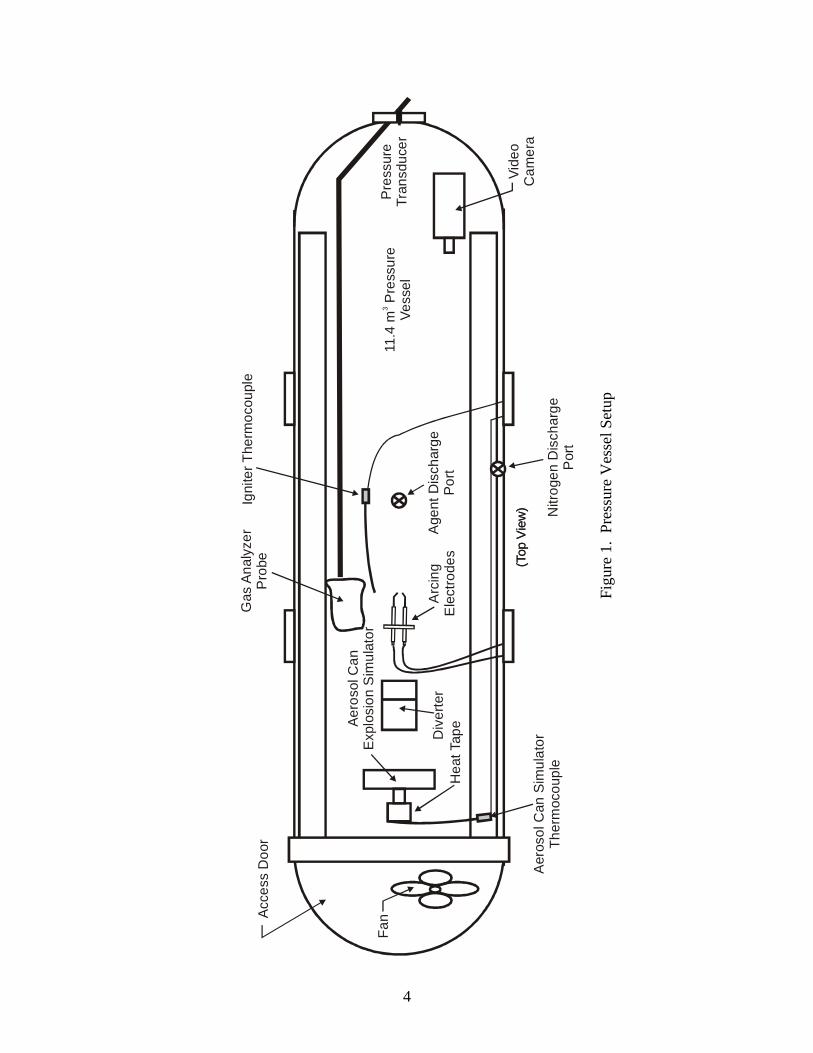
TEST SETUP. The aerosol can explosion simulation tests were conducted in Building 276, Pressure Fire Modeling Facility, at the FAA William J. Hughes Technical Center, Atlantic City International Airport, New Jersey. The aerosol can explosion simulator, used for the Aircraft Cargo Compartment MPS, was mounted inside the instrumented pressure vessel, as shown in figure 1. The following sections describe the facility, equipment, and systems used during the tests. PRESSURE VESSEL. The pressure vessel had a volume of 402.6 ft3
and a maximum working
pressure rating of 600 pounds per square inch gauge (psig) (see figure 1). The pressure vessel was instrumented with thermocouples, pressure transducers, gas analyzers, and a video camera. A TPI Industrial model F-18-TE fan was also placed in the pressure vessel to thoroughly mix the extinguishing agents before activating the aerosol can explosion simulator; the fan was set to low. Since the pressure vessel was air tight, the overpressure associated with the explosive reaction was captured and retained until the pressure vessel cooled. AEROSOL CAN EXPLOSION SIMULATOR. The aerosol can explosion simulator was developed by the FAA to simulate the worst-case effects of an exploding aerosol can in a repeatable manner. As shown in figure 1, the aerosol can explosion simulator was placed at the centerline of the pressure vessel near the access door. The aerosol can explosion simulator’s cylindrical steel body stored the base product explosive mixture (propane, alcohol, and water), was capable of withstanding 300 psi, and had a ball valve to rapidly discharge the base product explosive mixture. It was mounted vertically above the ball valve to allow complete expulsion of the base product explosive mixture (see figure 2). A discharge elbow was located vertically under the ball valve, which allowed the explosive contents to be ejected horizontally. The ball valve was capable of rotating from the fully closed position to the fully open position in less than 0.1 second to form a vapor cloud and was activated using a pneumatic actuator. The ignition source was located 3 feet from the simulator discharge port and 2 feet above the floor.
3
Pre
ssur
eTr
ansd
ucer
Vide
oC
amer
a(T
op V
iew
)(T
op V
iew
)
11.4
m P
ress
ure
Vess
el3
Fan
Aero
sol C
anE
xplo
sion
Sim
ulat
or
Arc
ing
Ele
ctro
des
Age
nt D
isch
arge
Port
Gas
Ana
lyze
rP
robe
Igni
ter T
herm
ocou
ple
Hea
t Tap
e
Aer
osol
Can
Sim
ulat
orTh
erm
ocou
ple
Div
erte
r
Nitr
ogen
Dis
char
geP
ort
Acce
ss D
oor
Figu
re 1
. Pr
essu
re V
esse
l Set
up
4
90-Degree Elbow
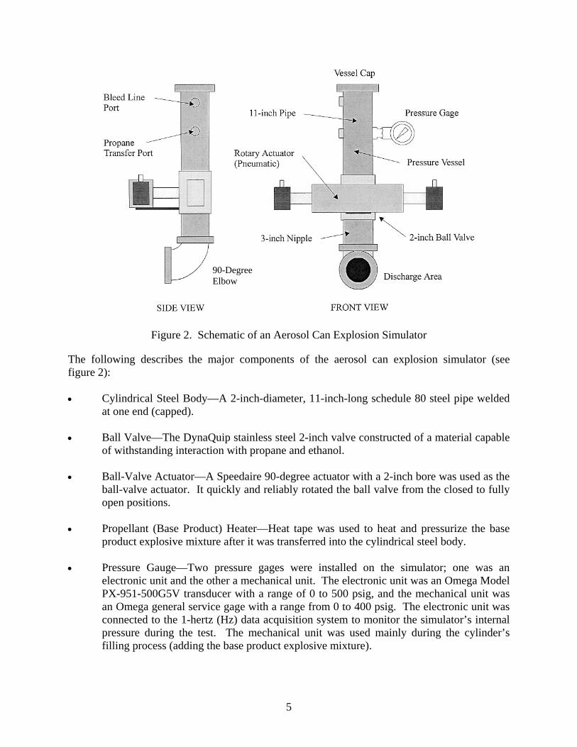
Figure 2. Schematic of an Aerosol Can Explosion Simulator
The following describes the major components of the aerosol can explosion simulator (see figure 2): • Cylindrical Steel Body—A 2-inch-diameter, 11-inch-long schedule 80 steel pipe welded
at one end (capped). • Ball Valve—The DynaQuip stainless steel 2-inch valve constructed of a material capable
of withstanding interaction with propane and ethanol. • Ball-Valve Actuator—A Speedaire 90-degree actuator with a 2-inch bore was used as the
ball-valve actuator. It quickly and reliably rotated the ball valve from the closed to fully open positions.
• Propellant (Base Product) Heater—Heat tape was used to heat and pressurize the base
product explosive mixture after it was transferred into the cylindrical steel body. • Pressure Gauge—Two pressure gages were installed on the simulator; one was an
electronic unit and the other a mechanical unit. The electronic unit was an Omega Model PX-951-500G5V transducer with a range of 0 to 500 psig, and the mechanical unit was an Omega general service gage with a range from 0 to 400 psig. The electronic unit was connected to the 1-hertz (Hz) data acquisition system to monitor the simulator’s internal pressure during the test. The mechanical unit was used mainly during the cylinder’s filling process (adding the base product explosive mixture).
5

• Propellant Mix—The base product (propellant) explosive mixture contained 3.2 ounces propane (20%), 9.6 ounces ethanol (denatured alcohol, 60%), and 3.2 ounces water (20%), for a total weight of 16 ounces [5].
INSTRUMENTATION. Multiple sensors were installed inside the pressure vessel during the evaluation, including thermocouples, gas analyzers, pressure transducers, and a video camera. The sensors were connected to either a 1-Hz or 1-kilohertz (kHz) data acquisition system.
Temperature Measurement. Two Type K chromel/alumel 22-gauge thermocouples measured the temperature near the arcing electrodes and the surface of the aerosol can explosion simulator. The thermocouple near the electrodes provided real-time readings of the pressure vessel’s internal temperature, and the thermocouple attached to the simulator was used to monitor the heat tape temperature to ensure it was functional during the pressurization of the simulator.
Gas Analyzers. Two gas analyzers, with a continuous real-time display, were used to measure the volumetric concentrations of Halon 1301 and oxygen. A single gas-sampling probe, connected to an external diaphragm-type pump via a bulkhead fitting, was installed inside the pressure vessel 24 inches laterally to the arcing electrode and 36 inches forward of the aerosol can explosion simulator. The extracted gas sample was regulated and metered to maintain a steady flow of 10 cubic centimeters to the gas analyzers. The volumetric concentration (VC) of Halon 1301 was measured with a Rosemount 880A (Nondispersive Infrared sensor) analyzer, and the oxygen volumetric concentration was measured with a Rosemount OM11EA gas analyzer. The extracted gas sample was returned to the pressure vessel after flowing through the analyzers. Using a two-way valve, the sampling probe was switched from collecting gas samples inside the pressure vessel to collecting air outside the pressure vessel, just before striking the arc, to protect the gas analyzers in the event of an overpressure.
The data-sampling rate for all the temperature measurements and the gas concentrations
was 1 Hz.
Pressure Measurement. Three pressure measurement devices were used to monitor the simulator and measure the overpressure during the explosion. As mentioned above, two pressure gages were installed on the simulator: an electronic unit connected to the 1-Hz data acquisition system and a mechanical unit. The electronic unit was an Omega Model PX-951-500G5V transducer with a range from 0 to 500 psig, and the mechanical unit was an Omega general service gage with a range from 0 to 400 psig. These units monitored the pressure inside the aerosol can explosion simulator during the filling process and the test. An Omega PX951-200G5V pressure transducer was mounted on the aft wall of the pressure vessel to record the overpressure pulses during the explosions. The pressure transducer’s frequency response was 3000 Hz, and it provided a pressure range from 0 to 200 psig. The pressure data of the electronic transducer connected to the aerosol can explosion simulator was collected with the 1-Hz data acquisition system, while the pressure data from the transducer attached to the pressure vessel wall was collected at a sampling rate of 1 kHz using the high-speed data acquisition system.
Video Camera. A CanonTM ZR500 digital video camera was used to monitor the pressure
vessel’s condition and record any explosive event. This camera included widescreen,
6

high-resolution recording, preprogrammed auto exposure settings, a Firewire/DV terminal, and an advanced image stabilization system.
Data Acquisition System. Two data acquisition systems were used to record the output
of the installed sensors: a 1-Hz system and a 1-kHz, high-speed system. The 1-Hz data acquisition system was a Computer Boards PCM-DAS16 system connected to a Gateway Solo laptop. Each channel was programmed to record data at 1 sample per second. The high-speed data acquisition system was a Keithley model DAS Scan Metrabyte connected to a Gateway model E-5200 personal computer. Each data channel was programmed to record 1 sample every 0.001 second. IGNITION SOURCE. A set of direct current spark igniters was used to ignite the base product explosive mixture discharged from the aerosol can explosion simulator. The igniters were connected to an ignition transformer capable of providing a 10,000-volt output and 0.023 amp (230W). These igniters were placed 36 inches from the point of discharge. The gap between the two spark igniters was set at 0.25 inch. The igniters were protected from the high-speed discharge by a diverter (sheet metal shield) that deflected the flow of the base product explosive mixture over the electrodes instead of going through them. HALON 1301 CYLINDER AND VALVE ASSEMBLIES. The Halon 1301 agent was stored in a 20-pound steel cylinder from Fenwal® (part number 44-100020-001). It was stored as a liquid and superpressurized with nitrogen to 360 psig at 70°F. The cylinder valve assembly was equipped with a pressure gauge and a safety burst disc in compliance with Department of Transportation requirements. The cylinder was designed for an operating temperature range of 0°F to 130°F. Its temperature-pressure relationship was based on a maximum fill density of 70 lb/ft3. The Halon 1301 cylinder was plumbed to the pressure vessel using 1-inch pipe. A nozzle, designed for this specific extinguishing agent, was connected at the end of the 1-inch pipe inside the pressure vessel at ceiling level. The agent was discharged electronically using an electronic control head that was connected to the cylinder’s actuation port. NITROGEN GENERATOR. The Air Liquide Floxal® nitrogen generator, which supplied the nitrogen gas for this research, was a general-purpose (off-the-shelf), hollow-fiber membrane (HFM) gas separation nitrogen-enriched air (NEA) generator. The unit contained one 6-inch-diameter gas separation module, allowing the unit to generate as much as 25 cubic feet per minute (CFM) of 95% NEA (5% oxygen by volume). The oxygen concentration was monitored with the OM11EA oxygen analyzer, which was calibrated with air and gave an output in percent by volume. The NEA was supplied through a flow meter mounted on the NEA generator. This equipment contained an air purification system consisting of a filter, several layers of water desiccation (drying), and a carbon activation tower. Shop compressor air purification was required to ensure the integrity and reliability of the HFM air separation modules. The NEA output port was connected to the pressure vessel via a 1.5-inch inner diameter hose. At the pressure vessel entry port, a two-way solenoid valve diverted the nitrogen from inside the pressure vessel to outside the building when the desired oxygen volumetric concentration was reached.
7

TEST PROCEDURE. The test procedure is outlined below: 1. The Halon 1301 and oxygen analyzers were turned on and given the proper amount of
warm-up time, as specified (4 hours minimum). They were calibrated with a certified mixture consisting of 6.38% Halon 1301 (balanced with nitrogen), 20.94% certified purity compressed oxygen, and zero product-grade compressed nitrogen.
2. The aerosol can explosion simulator was filled with 0.2 pound of water, 0.6 pound of
alcohol, and 0.2 pound of propane. Once filled, it was installed inside the pressure vessel.
3. The Halon 1301 fire bottle was filled with the proper amount of agent, superpressurized
to 360 psig, and its valves connected to the pressure vessel. 4. The nitrogen gas generator, connected to the pressure vessel via a 1.5-inch hose, was
turned on. 5. The pressure vessel door was hydraulically locked and its vent closed. But the main port
valve was left opened to allow air to leak out as the NEA was injected. (It was closed before the Halon 1301 was added.)
6. The 1-Hz data acquisition system and video recorder were started, and the aerosol can
explosion simulator heater was turned on. The simulator’s pressure was monitored and was kept as close to 240 psig as possible by cycling the heat tape on and off, as needed (with the computer).
7. The fan inside the pressure vessel was turned on to thoroughly mix the gases inside the
pressure vessel. 8. As needed, the nitrogen gas generator system’s valve was opened and nitrogen was
injected into the pressure vessel until the desired oxygen concentration was reached. The pressure vessel’s main port valves were closed after reaching steady state. After reaching the steady-state concentration, the Halon 1301 container was discharged.
9. The analyzers’ two-way valve was switched to collect air outside the pressure vessel to
prevent the analyzers from damage from the blast. 10. The igniter (arcing electrodes) was turned on, and the base product explosive mixture
inside the aerosol can explosion simulator was released. 11. The test concluded after the event or nonevent. With the exception of the analyzers, all
the systems were then deactivated or turned off, and the collected data was saved.
8

12. The pressure vessel was opened and ventilated for approximately 1 hour before running the next test.
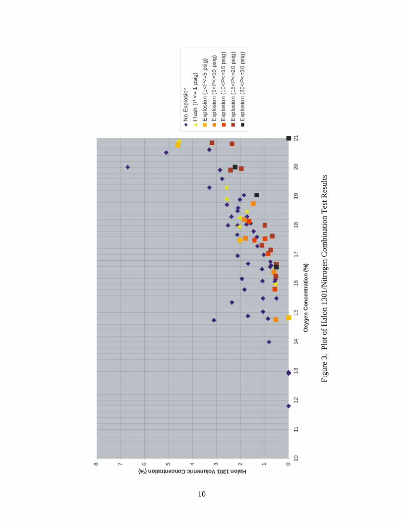
DATA ANALYSIS METHOD. A literature search was conducted to determine the minimum design concentrations (Halon 1301) and minimum oxygen concentrations (nitrogen) to protect against a propane and ethanol threat. This literature data and the collected experimental data were plotted in a Cartesian chart to determine if beneficial effects between these two fire-extinguishing gases existed. As previously stated, the published concentrations of Halon 1301 and oxygen concentration to inert a propane (stoichiometric) explosion were 6.7% and 11.8%, respectively. For ethanol, the Halon 1301 concentration was 11.1% and the oxygen concentration was 8.6% by volume. Although the literature data was based on a different test protocol, they provided some values as boundaries during the analysis of the experimental data. The data from the literature used standard test protocols at stoichiometric concentrations, while the tests conducted in this project, using the aerosol can explosion simulator, had explosive concentrations that varied between the lower and upper explosive limits. If a benefit existed by combining these two gases, it would be evidenced by the prevention of explosions at concentrations below their inerting values (see figure 3). Figure 3 shows a Cartesian chart illustrating the oxygen VC on the x axis and the Halon 1301 VC on the y axis. The data points were color-coded, depending on the resulting event after the simulator was activated: • Blue Diamond—for no explosion • Yellow Triangle—for a flash explosion with less or equal to 1 psig overpressure • Light Orange Square—for an explosion with an overpressure greater than 1 psig and less
or equal to 5 psig • Dark Orange Square—for an explosion with an overpressure greater than 5 psig and less
or equal to 10 psig • Red Square—for an explosion with an overpressure greater than 10 psig and less or equal
to 15 psig • Black and Red Square—for an explosion with an overpressure greater than 15 psig and
less or equal to 20 psig • Black Square—for an explosion with an overpressure greater than 20 psig and less or
equal to 30 psig
9
012345678
1011
1213
1415
1617
1819
2021
Oxy
gen
Con
cent
ratio
n (%
)
Halon1301VolumetricConcentration(%)
No
Expl
osio
nFl
ash
(P <
= 1
psig
)
Exp
losi
on (1
<P<=
5 ps
ig)
Exp
losi
on (5
<P<=
10 p
sig)
Exp
losi
on (1
0<P<
=15
psig
)
Exp
losi
on (1
5<P<
=20
psig
)E
xplo
sion
(20<
P<=3
0 ps
ig)
Figu
re 3
. Pl
ot o
f Hal
on 1
301/
Nitr
ogen
Com
bina
tion
Test
Res
ults
10

RESULTS
Tables 1 through 7 present data from the literature search and the results of the 70 tests conducted. The first column identifies the test name, the second and third columns show the oxygen and Halon 1301 VC, the fourth column presents the event reaction (resultant pressure), and the last column was reserved for comments. Figure 3 is a graphical representation of the same data, but in a Cartesian chart format with the event color-coded on the data points.
Table 1. Results: No Explosion Data
Test ID Oxygen
(%) Halon 1301
(%) Reaction Comments 11.80 0 No explosion Literature
071902T1 12.92 0 No explosion 051502T6 12.96 0 No explosion 052102T4 15.50 0.507 No explosion 070202T1 16.14 0.550 No explosion 071002T3 16.07 0.570 No explosion 071002T1 16.63 0.730 No explosion 070802T2 16.75 0.755 No explosion 071002T2 16.58 0.760 No explosion 032707T4 14.00 0.810 No explosion N2 introduced to 15%, but
added more to reach 14% after injecting Halon 1301. File name Explosion Test 032907T1b
033007T1 14.80 0.860 No explosion N2 introduced to 16%, but added more to reach 14.8% after injecting Halon 1301
070802T3 16.99 1.034 No explosion 051402T5 15.04 1.060 No explosion 072502T2 15.50 1.060 No explosion 051602T1 16.09 1.080 No explosion 062802T1 16.50 1.100 No explosion 071702T1 17.29 1.300 No explosion 051502T2 17.60 1.320 No explosion 070102T3 17.80 1.460 No explosion 062802T3 18.07 1.580 No explosion 062802T2 16.69 1.680 No explosion 051402T3 14.89 1.690 No explosion
11

Table 1. Results: No Explosion Data (Continued)
Test ID Oxygen
(%) Halon 1301
(%) Reaction Comments 032907T1 18.30 1.730 No explosion N2 introduced at 19%, but dropped
to 18.3% after injecting Halon 1301 070102T1 18.04 1.750 No explosion 033007T2 15.80 1.830 No explosion N2 introduced at 17%, but dropped
to 15.8% after injecting Halon 1301 051502T4 19.04 1.860 No explosion 032107T2 16.17 1.940 No explosion N2 introduced at 18.3%, but dropped
to 17.3% after injecting Halon 1301 052102T1 18.89 2.030 No explosion 032607T3 17.50 2.040 No explosion 082702T2 18.60 2.105 No explosion 032207T1 16.96 2.120 No explosion N2 introduced at 18%, but dropped
to 17% after injecting Halon 1301 032307T1 1800 2.120 No explosion N2 introduced at 19%, but dropped
to 18% after injecting Halon 1301 032307T5 18.50 2.120 No explosion N2 introduced at 19.5%, but dropped
to 18.5% after injecting Halon 1301 071702T3 17.68 2.130 No explosion 051402T2 15.36 2.360 No explosion 032707T5 18.30 2.380 No explosion 040307T1 1800 2.520 No explosion N2 introduced at 19%, but dropped
to 18% after injecting Halon 1301 032307T2 18.71 2.570 No explosion N2 introduced at 19.5%, but dropped
to 18.8% after injecting Halon 1301 032707T1 19.60 2.770 No explosion N2 introduced at 18.0%, but dropped
to 17.2% after injecting Halon 1301 052102t3 19.90 2.850 No explosion 032107t1 14.75 3.110 No explosion N2 introduced at 17%, but dropped
to 16% after injecting Halon 1301 040307T2 19.30 3.290 No explosion N2 introduced at 20.5%, but dropped
to 19.3% after injecting Halon 1301 051302T1 20.60 3.300 No explosion 071802T4 20.50 5.100 No explosion 2000 6.700 No explosion Literature
12
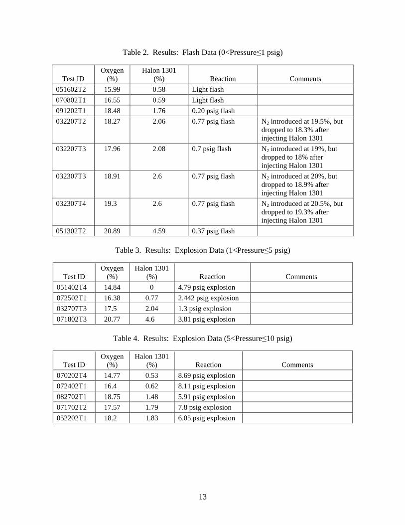
Table 2. Results: Flash Data (0<Pressure≤1 psig)
Test ID Oxygen
(%) Halon 1301
(%) Reaction Comments 051602T2 15.99 0.58 Light flash 070802T1 16.55 0.59 Light flash 091202T1 18.48 1.76 0.20 psig flash 032207T2 18.27 2.06 0.77 psig flash N2 introduced at 19.5%, but
dropped to 18.3% after injecting Halon 1301
032207T3 17.96 2.08 0.7 psig flash N2 introduced at 19%, but dropped to 18% after injecting Halon 1301
032307T3 18.91 2.60 0.77 psig flash N2 introduced at 20%, but dropped to 18.9% after injecting Halon 1301
032307T4 19.30 2.60 0.77 psig flash N2 introduced at 20.5%, but dropped to 19.3% after injecting Halon 1301
051302T2 20.89 4.59 0.37 psig flash
Table 3. Results: Explosion Data (1<Pressure≤5 psig)
Test ID Oxygen
(%) Halon 1301
(%) Reaction Comments 051402T4 14.84 0 4.79 psig explosion 072502T1 16.38 0.77 2.442 psig explosion 032707T3 17.50 2.04 1.3 psig explosion 071802T3 20.77 4.60 3.81 psig explosion
Table 4. Results: Explosion Data (5<Pressure≤10 psig)
Test ID Oxygen
(%) Halon 1301
(%) Reaction Comments 070202T4 14.77 0.53 8.69 psig explosion 072402T1 16.40 0.62 8.11 psig explosion 082702T1 18.75 1.48 5.91 psig explosion 071702T2 17.57 1.79 7.8 psig explosion 052202T1 18.20 1.83 6.05 psig explosion
13
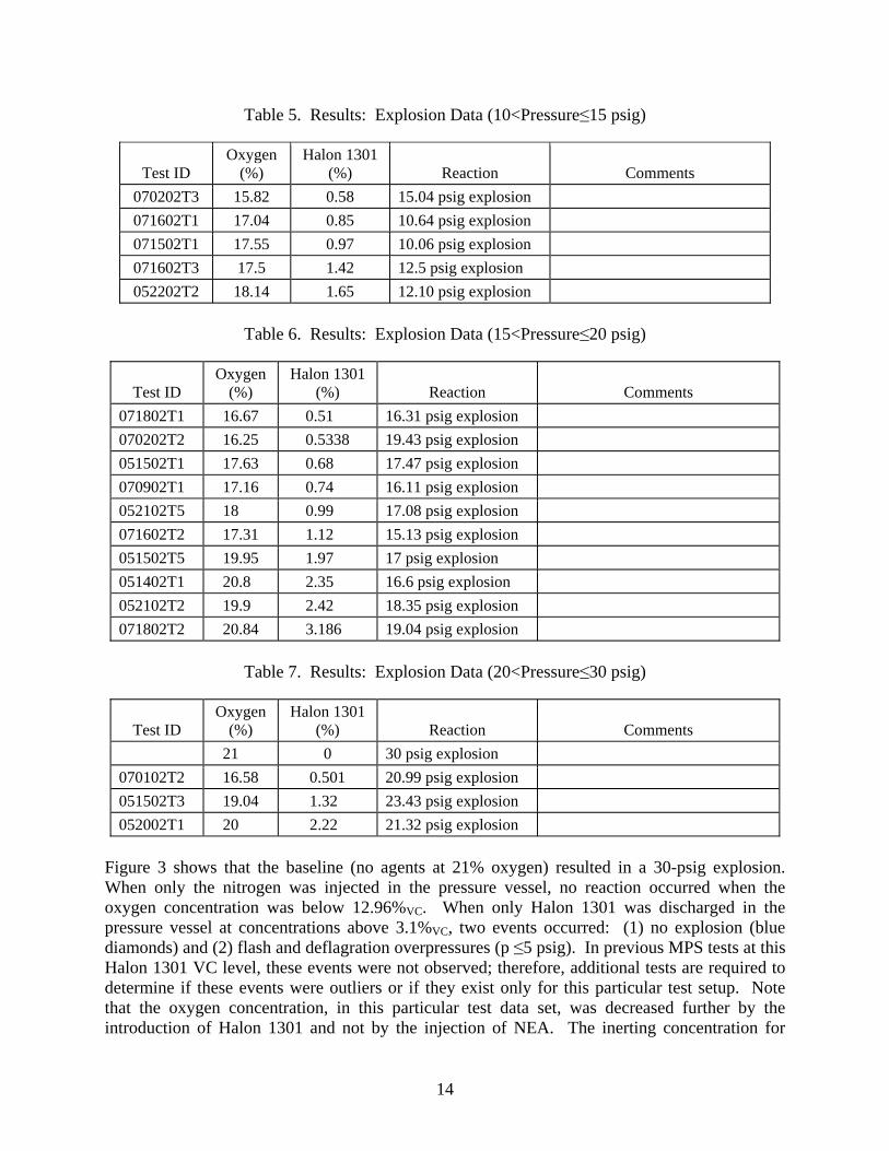
Table 5. Results: Explosion Data (10<Pressure≤15 psig)
Test ID Oxygen
(%) Halon 1301
(%) Reaction Comments 070202T3 15.82 0.58 15.04 psig explosion 071602T1 17.04 0.85 10.64 psig explosion 071502T1 17.55 0.97 10.06 psig explosion 071602T3 17.5 1.42 12.5 psig explosion 052202T2 18.14 1.65 12.10 psig explosion
Table 6. Results: Explosion Data (15<Pressure≤20 psig)
Test ID Oxygen
(%) Halon 1301
(%) Reaction Comments 071802T1 16.67 0.5100 16.31 psig explosion 070202T2 16.25 0.5338 19.43 psig explosion 051502T1 17.63 0.6800 17.47 psig explosion 070902T1 17.16 0.7400 16.11 psig explosion 052102T5 18.00 0.9900 17.08 psig explosion 071602T2 17.31 1.1200 15.13 psig explosion 051502T5 19.95 1.9700 17 psig explosion 051402T1 20.80 2.3500 16.6 psig explosion 052102T2 19.90 2.4200 18.35 psig explosion 071802T2 20.84 3.1860 19.04 psig explosion
Table 7. Results: Explosion Data (20<Pressure≤30 psig)
Test ID Oxygen
(%) Halon 1301
(%) Reaction Comments 21.00 0 30 psig explosion 070102T2 16.58 0.501 20.99 psig explosion 051502T3 19.04 1.320 23.43 psig explosion 052002T1 20.00 2.220 21.32 psig explosion
Figure 3 shows that the baseline (no agents at 21% oxygen) resulted in a 30-psig explosion. When only the nitrogen was injected in the pressure vessel, no reaction occurred when the oxygen concentration was below 12.96%VC. When only Halon 1301 was discharged in the pressure vessel at concentrations above 3.1%VC, two events occurred: (1) no explosion (blue diamonds) and (2) flash and deflagration overpressures (p ≤5 psig). In previous MPS tests at this Halon 1301 VC level, these events were not observed; therefore, additional tests are required to determine if these events were outliers or if they exist only for this particular test setup. Note that the oxygen concentration, in this particular test data set, was decreased further by the introduction of Halon 1301 and not by the injection of NEA. The inerting concentration for
14
oxygen was higher than the published values, 11.8%VC and 6.7%VC for propane and ethanol, respectively. This may have been caused by the way the base product explosive mixture was introduced during the ignition process. The base product explosive mixture could have been too rich or too lean while traveling horizontally towards the ignitors. Water was also mixed with the propane and alcohol, which could have influenced the values due to its high heat capacity (cooling effects). For this study, the literature VC values were considered the inert boundaries. For analysis purposes, any “No Explosion” blue diamond above 12.96%VC oxygen and below 3.1%VC Halon 1301 would be considered a benefit. In figure 3, a blue diamond was observed when the oxygen concentration was at 14%VC and the Halon 1301 was at 0.81%VC. Furthermore, blue diamonds were observed as the oxygen was increased from 14% to 17%VC with only 1%VC of Halon 1301. It seems that a transitional point occurred between 17%VC and 18%VC oxygen (and Halon 1301 VC > 1%), since no explosion events or explosion events occurred when Halon 1301 was at concentrations between 1%VC and 2.12%VC. Of course, at higher Halon 1301 concentrations, the explosive event was prevented. As the oxygen concentration was increased from 18% to 20%, more Halon 1301 was required to prevent an explosion, in an almost lineal fashion—from 2.5% VC to 2.9% VC. The data showed that a clear benefit existed when Halon 1301 and nitrogen were present at subinert concentrations. Explosions were prevented, particularly at lower oxygen concentrations with relatively small amounts of Halon 1301. At oxygen concentrations near or at 21%, the amount of Halon 1301 required is more significant, about 3%. The nitrogen and Halon 1301 were working together to combat the fire; i.e., Halon 1301 interrupted the combustion chain with less oxygen in the flammable mixture.
CONCLUSIONS
Beneficial effects resulted when Halon 1301 and nitrogen were combined to inert a closed pressure vessel (compartment) against an explosion from an aerosol can explosion simulator apparatus containing propane, alcohol, and water. Less Halon 1301 was needed to inert a compartment having an oxygen-depleted environment. This means that in a typical aircraft cargo compartment fire protection system configuration, with a dual-stage discharge (high-rate/low-rate discharge), it may be more feasible to replace one of the two Halon 1301 fire bottles with a nitrogen generator system. This approach would work well in an aircraft with an available onboard inert gas generation system to prevent fuel tank explosions. The system integration could reduce the amount of Halon 1301 from the aircraft cargo compartment fire suppression system by 50% or more.
15
16
REFERENCES
1. Department of Transportation, Federal Aviation Administration, FAR Final Rule, Revised Standards for Cargo or Baggage Compartments in Transport Category Airplanes, Federal Register: February 17, 1998 (Vol. 63, No. 31) pp. 8032.
2. Reynolds, T., Bailey, D., Lewinski, D., and Roseburg, C., “Onboard Inert Gas Generation
System/Onboard Oxygen Gas Generation System (OBIGGS/OBOGS) Study,” NASA Report NA S1-20341, July 2000, pp. 62.
3. Securaplane Technologies, Inc., “Pilot’s Guide Securaplane ST-3000 Fire Detection and
Suppression System,” July 2000, pp. 3.
4. Reinhardt, J., “The Evaluation of Water Mist With and Without Nitrogen as an Aircraft Cargo Compartment Fire Suppression System,” FAA report DOT/FAA/AR-01/121, February 2002, pp. 13.
5. Reinhardt, J., “Minimum Performance Standard for Aircraft Cargo Compartment Halon
Replacement Fire Suppression Systems (2nd
Update),” FAA report DOT/FAA/AR-TN05/20, June 2005, pp. 5-8.
6. Reinhardt, J., “Behavior of Bromotrifluoropropene and Pentafluoroethane When
Subjected to a Simulated Aerosol Can Explosion,” FAA report DOT/FAA/AR-TN04/4, May 2004.
7. National Fire Protection Association (NFPA), “Theory of Fire Extinguishment,” Fire
Protection Handbook, 18th Edition, Chapter 1, pp. 1997, 1-97-99.
8. National Fire Protection Association (NFPA), “NFPA 12A: Halon 1301 Fire Extinguishing Systems,” 1992, pp. 12A-11.
9. Möller, W., Molnarne, M., and Sturm, R., “Limiting Oxygen Concentration: Recent
Results and their Presentation in Chemsafe,” 9th International Symposium on Loss Prevention and Safety Promotion in the Process Industries, May 1998, Barcelona, Spain. http://www.ptb.de/de/org/3/34/341/moeller.htm.