Embed Size (px)
Citation preview
Preventative vs. Predictive Motor Maintenance
99 Ortona Ct, Concord, ON L4K 3M3, Canada / 877-742-3665
www.renown-electric.com / [email protected]
Table of Contents
Introduction .......................................................................................2
Vibration Analysis ............................................................................5
Vibration Due to Bearing Problems ................................ 6
Vibration Due to Stator Problems ................................... 8
Infrared Analysis ............................................................................. 9
Motor Drive Alignment ................................................................11
Winding Analysis ............................................................................ 12
Onsite Balancing ............................................................................ 13
Oil Analysis ....................................................................................... 14
Practical PM Procedures ............................................................. 15
Conclusion .........................................................................................18

99 Ortona Ct, Concord, ON L4K 3M3, Canada / 877-742-3665
www.renown-electric.com / [email protected]
Introduction
Electric motors are part of our everyday lives. From your washing machine, furnace and dishwasher to your workplace, electric motors play an important part in the residential, industrial and commercial environments with over 1.2 billion of all types of electric motors used throughout the United States. Electric Motors consume 78% of all electrical energy in industrial processes, 43% of electrical energy in commercial buildings and 37% of the electrical energy in residential environments. The vast majority of the electricity used by an electric motor drive system is consumed by the electric motor. Only a very small amount is used to power control functions or other ancillary circuits. Electric motors and the systems they drive are the single largest user of electricity, consuming more than twice as much as lighting. The largest proportion of motor electricity consumption is attributable to mid-size motors with output power of 0.75 kW to 375 kW.
Technically, an electric motor is an electric machine that converts electrical energy into mechanical energy. One type that is used in industry is an AC motor. This type of electric motor is driven by an alternating current (AC). It commonly consists of two basic parts, an outside stationary stator having coils supplied with alternating current to produce a rotating magnetic field, and an inside rotor attached to the output shaft that is given a torque by the rotating field.There are two main types of AC motors, depending on the type of rotor used. The first type is the induction motor or asynchronous motor. This type relies on a small difference in speed between the rotating magnetic field and the rotor to induce rotor current. The second type is the synchronous motor, which does not rely on induction and as a result can rotate exactly at the supply frequency or a sub-multiple of the supply frequency. The magnetic field on the rotor is either generated by current delivered through slip rings or by a permanent magnet. Electric motors are often allowed to run with minimal maintenance until output is down due to a burnout or catastrophic bearing failure.
As operating hours mount, reliability decreases and over time, will ultimately result in failure. Although some equipment faults are immediate, the majority of failures that influence production are the result of the poor execution or lack of a maintenance program. This type of failure is largely due to management not fully understanding that maintenance is an investment in the business and not just an expense of doing business. Proper implementation of a maintenance program has been shown to decrease energy consumption in plants by as much as 14%, while also reducing unplanned production downtime.
"Although some equipment faults are immediate, the majority of failures that influence production are the result of the poor execution or lack of a maintenance program."

99 Ortona Ct, Concord, ON L4K 3M3, Canada / 877-742-3665
www.renown-electric.com / [email protected]
Introduction (cont.)
There are several ways of carrying out maintenance on electric motors. The first is simply run until failure. Many plants still operate with a “run to failure” maintenance strategy. In this mode, no actions are taken until machinery fails. Maintenance costs and production losses can be quite high when dealing with large and expensive motors. This may be a solution where the equipment is less expensive such as small motors in easy access locations, robots, non-critical equipment such as fans or where redundant systems are used. Careful consideration of downtime costs and availability of spares needs to be paramount in the decision for this plan to be effective.
Preventative Motor Maintenance (PM) is a calendar or time-based planned or schedule-based maintenance program where actions are scheduled regardless of the actual condition of the equipment. This type of maintenance can be very effective if the ability to shut-down or do any kind of motor repair is exceptionally high while the equipment is set up or in production. A well-planned preventive maintenance program is the key to dependable, long-life operation of electric motors. In modern plant operations, unscheduled shutdowns in production or long repair shutdowns are very costly. The high cost of the ensuing downtime eats deeply into profits. Although management probably realizes the value of a good preventive maintenance (PM) program, they sometimes resist because the return on investment is not readily apparent.
Predictive or condition-based Motor Maintenance (PdM), is where machines are measured with objective machine monitored trending methods such as, vibration analysis and infrared thermal imaging. PdM is a valuable tool since it doesn’t require tearing a machine down to find out its condition. PdM defines methods to predict or diagnose problems in a piece of equipment based on trending of test results. These methods use non-intrusive testing techniques to measure and calculate performance trends for the equipment. Condition-based Maintenance (CBM) is a methodology that combines predictive and preventive maintenance with real-time monitoring. PdM uses Condition-based Maintenance systems to detect fault sources well in advance of failure, making maintenance a proactive process. CBM accurately detects the current state of mechanical systems and predicts the systems’ ability to perform without failure. It uses the potential failure levels created during the machinery design process, measures suitable parameters to quantify the existing failure levels, and adjusts the operating environment to make these levels compatible with economic production versus equipment lifetimes.
99 Ortona Ct, Concord, ON L4K 3M3, Canada / 877-742-3665
www.renown-electric.com / [email protected]
Vibration Analysis
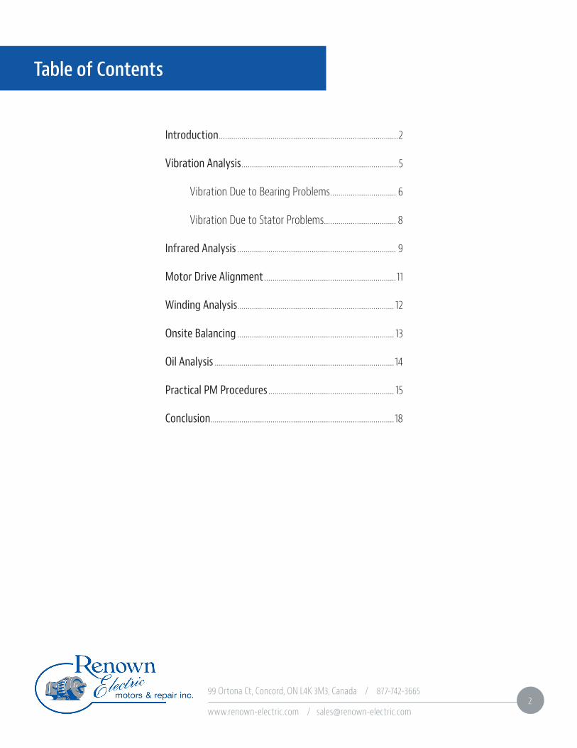
Vibration analysis is one of the most commonly used predictive maintenance technologies for rotating equipment in industry today. In the world of mechanical maintenance, vibration remains one of the earliest indicators of a machine’s health. Utilizing various types of instrumentation, equipment condition is monitored and internal component faults are identified, measured, and quantified. Through this process, critical failure of mechanical equipment can be avoided while extending the life cycle of monitored equipment. Vibration analysis for electric motors can cover a wide range of equipment in today’s modern industrial environment. Basically, if it “turns on a shaft,” equipment can effectively be monitored under a proactive vibration analysis program.
All rotating equipment generates a unique vibration signal or “signature.” These unique signals (also known as frequency) are usually captured in series, with the signal’s amplitude (y-axis) depicted over time (x-axis). This is called a time waveform. Individual vibration signals combine to form a complex time waveform showing overall vibration. Pattern recognition is a key part of vibration analysis…but significant training and experience are necessary to read the patterns. Four common results of excessive vibration are imbalance, misalignment, looseness, and bearing failure. It is very important to have a record of the machine vibration baseline history. For optimal results, baseline data is recorded during the first few hours of operation at initial startup. A subsequent reading immediately following the machine break-in period is very useful to establish the true baseline for a machine condition monitoring program to be the most effective. Even if you have equipment in place, vibration analysis can be carried out to determine if there are any issues, using this as a baseline.

99 Ortona Ct, Concord, ON L4K 3M3, Canada / 877-742-3665
www.renown-electric.com / [email protected]
Vibration Analysis (cont.)
The requirement for obtaining housing vibration data vs. shaft vibration data depends on the problem. It is often desirable to obtain both, especially on a machine with sleeve bearings. If the problem originates in the housing or motor frame (for example, twice line frequency vibration), it is important to gather housing vibration data with magnetically mounted accelerometers. If the problem originates in the rotor (unbalance or oil whirl, for instance), you should obtain shaft vibration data with either a shaft stick or a proximity probe.
Proximity probes yield vibration data of the shaft movement relative to the housing, whereas shaft stick measurements yield vibration data based on an absolute reference location. Obtain shaft stick measurements by placing a handheld accelerometer attached to a wood fishtail stick against a smooth rotating surface on the motor shaft. If the motor comes with proximity probes, use them. If it does not and relative shaft vibration is required, set up proximity probes with magnetic mounts. Always obtain housing vibration data with an absolute reference. Vibration Due to Bearing Problems Bearings are small compared to other major motor components, making them particularly vulnerable to damage and wear. It’s no surprise then, that studies blame more than half of all motor failures on bearing malfunction, most of which result from too little or too much lubrication. The key to avoiding these conditions is to establish a lubrication program using bearing and motor manufacturer guidelines to determine the frequency and amount of lubrication for the motor application, duty (continuous or intermittent), environmental conditions, and bearing size.
Bearing-related issues are among the most common causes of electric motor failures and often result in excessive vibration before a failure. Problems with bearings cause more than half of all motor failures, because of this, special attention must be paid to bearings, bearing housings, and shafts when carrying out inspections and maintenance of motors. Remember to rotate spare motors in storage on a quarterly basis, to avoid the weight of the rotor and shaft assembly causing a small dent in the bearings’ outer race. This small dent will immediately create noise once the motor is placed in service. The dent will also appear in the vibration signature at one times RPM.
"By solving bearing problems motor failures will almost certainly be reduced."
99 Ortona Ct, Concord, ON L4K 3M3, Canada / 877-742-3665
www.renown-electric.com / [email protected]
Vibration Analysis (cont.)
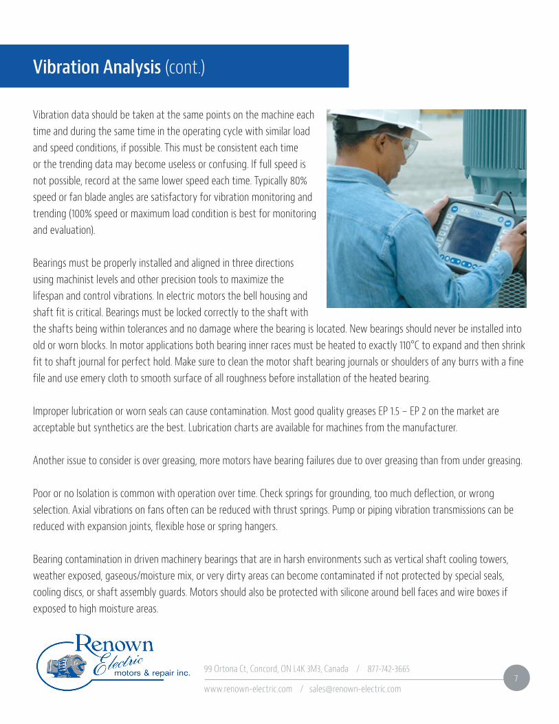
Vibration data should be taken at the same points on the machine each time and during the same time in the operating cycle with similar load and speed conditions, if possible. This must be consistent each time or the trending data may become useless or confusing. If full speed is not possible, record at the same lower speed each time. Typically 80% speed or fan blade angles are satisfactory for vibration monitoring and trending (100% speed or maximum load condition is best for monitoring and evaluation).
Bearings must be properly installed and aligned in three directions using machinist levels and other precision tools to maximize the lifespan and control vibrations. In electric motors the bell housing and shaft fit is critical. Bearings must be locked correctly to the shaft with the shafts being within tolerances and no damage where the bearing is located. New bearings should never be installed into old or worn blocks. In motor applications both bearing inner races must be heated to exactly 110°C to expand and then shrink fit to shaft journal for perfect hold. Make sure to clean the motor shaft bearing journals or shoulders of any burrs with a fine file and use emery cloth to smooth surface of all roughness before installation of the heated bearing.
Improper lubrication or worn seals can cause contamination. Most good quality greases EP 1.5 – EP 2 on the market are acceptable but synthetics are the best. Lubrication charts are available for machines from the manufacturer. Another issue to consider is over greasing, more motors have bearing failures due to over greasing than from under greasing. Poor or no Isolation is common with operation over time. Check springs for grounding, too much deflection, or wrong selection. Axial vibrations on fans often can be reduced with thrust springs. Pump or piping vibration transmissions can be reduced with expansion joints, flexible hose or spring hangers. Bearing contamination in driven machinery bearings that are in harsh environments such as vertical shaft cooling towers, weather exposed, gaseous/moisture mix, or very dirty areas can become contaminated if not protected by special seals, cooling discs, or shaft assembly guards. Motors should also be protected with silicone around bell faces and wire boxes if exposed to high moisture areas.

99 Ortona Ct, Concord, ON L4K 3M3, Canada / 877-742-3665
www.renown-electric.com / [email protected]
Motors that are operating with a variable frequency drive (VFD) can often develop a problem which is caused by voltage build up in the rotor and the milliamps discharge (micro-arcing) through the bearings back to the stator. The result is loud bearing noises from pitting, glazing, micro-cracks and craters of the rolling elements and raceways along with burned/contaminated grease. Vibration Due to Stator Problems Stator faults are often considered one of the most controversial fault zones due to the significant challenges in early fault detection and the prevention of motor failure surrounding the stator windings.
This challenge is further intensified in higher voltage machines, where the fault to failure time frame becomes much shorter. Stator faults are identified as the health and quality of the insulation between the turns and phases of the individual turns and coils inside the motor.
The stator coils can and do move during operation of the motor, especially when the motor is initially started. When the motor is started, the current in the coils is at its highest which resultsin a high magnetic force that causes the coils to vibrate at two times line frequency. This vibration causes the coils to move which can result in damage to the stator, rotor, and other motor components. Bearing failures and misalignment can cause the motor to strike the stator, which can result in grounded coils, excessive heat generation, or severe damage to both the rotor and stator. It is important to have your motors repaired by a qualified service facility and to ensure motors are wound (where applicable) using class H insulation and inverter duty wire to obtain optimal motor life. Initial quality of the new motor and, as importantly, the quality of the repair process including parts used in the repair will greatly impact problems in motor vibration.
Vibration Analysis (cont.)
"Bearing failures and misalignment can cause the motor to strike the stator, which can result in grounded coils, excessive heat generation, or severe damage to both the rotor and stator."
99 Ortona Ct, Concord, ON L4K 3M3, Canada / 877-742-3665
www.renown-electric.com / [email protected]
Infrared Analysis
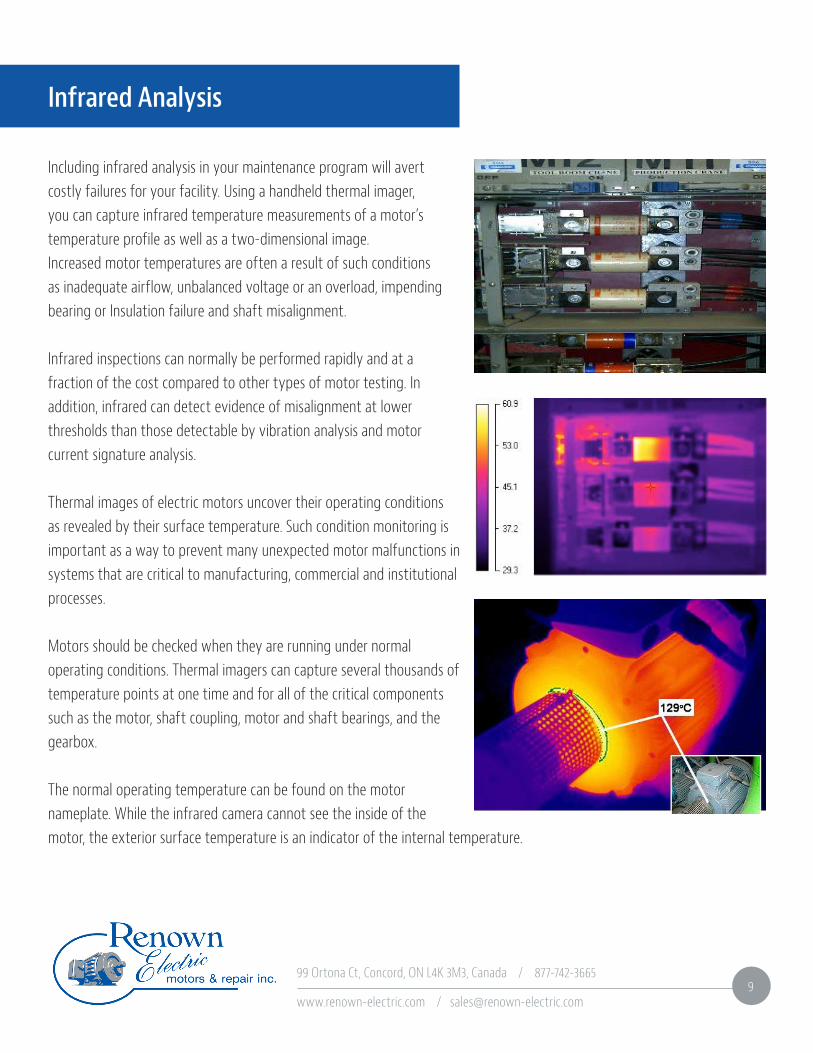
Including infrared analysis in your maintenance program will avert costly failures for your facility. Using a handheld thermal imager, you can capture infrared temperature measurements of a motor’s temperature profile as well as a two-dimensional image.Increased motor temperatures are often a result of such conditions as inadequate airflow, unbalanced voltage or an overload, impending bearing or Insulation failure and shaft misalignment.
Infrared inspections can normally be performed rapidly and at a fraction of the cost compared to other types of motor testing. In addition, infrared can detect evidence of misalignment at lower thresholds than those detectable by vibration analysis and motor current signature analysis.
Thermal images of electric motors uncover their operating conditions as revealed by their surface temperature. Such condition monitoring is important as a way to prevent many unexpected motor malfunctions in systems that are critical to manufacturing, commercial and institutional processes.
Motors should be checked when they are running under normal operating conditions. Thermal imagers can capture several thousands of temperature points at one time and for all of the critical components such as the motor, shaft coupling, motor and shaft bearings, and the gearbox. The normal operating temperature can be found on the motor nameplate. While the infrared camera cannot see the inside of the motor, the exterior surface temperature is an indicator of the internal temperature.
99 Ortona Ct, Concord, ON L4K 3M3, Canada / 877-742-3665
www.renown-electric.com / [email protected]
As added precautions, the following inspections can also be made. With the motor cover removed, inspect electrical connections at the motor junction box. This should be done in conjunction with the regularly scheduled inspection of the facility’s electrical system. Inspect motor casing for hot spots which may indicate short circuits within motor windings. Compare individual motors to similar motors under a similar load. When possible, compare inboard and outboard bearings for each motor. If a large difference is present, it may indicate misalignment or a rotor balance problem. If both bearings are hot, the bearings may be worn or improperly lubricated.Loose winding connections are another issue that can generate heat. Hot spots in the windings or connections can be investigated and repaired before there is a problem.
A stator-winding fault can cause significant rises in temperature and can be caused by a turn-to-turn, phase-to-phase, or turn-to-ground short. A turn-to-turn short is identified as a short circuit of one or more windings in a coil. This can develop into a very low impedance loop of wire, which acts as a shorted secondary of a current transformer. This results in excessive current flow through the shorted loop, creating intense heat and insulation damage.
When a motor is started with a broken or cracked rotor bar, excessive heat can be generated in the proximity of the broken bar. This can spread to other rotor bars and destroy the insulation around the nearby laminations. It can also affect other parts of the motor such as the stator. Stator insulation cannot hold up to the intense heat developed by the broken rotor bar and will eventually fail.
Infrared Analysis (cont.)
99 Ortona Ct, Concord, ON L4K 3M3, Canada / 877-742-3665
www.renown-electric.com / [email protected]
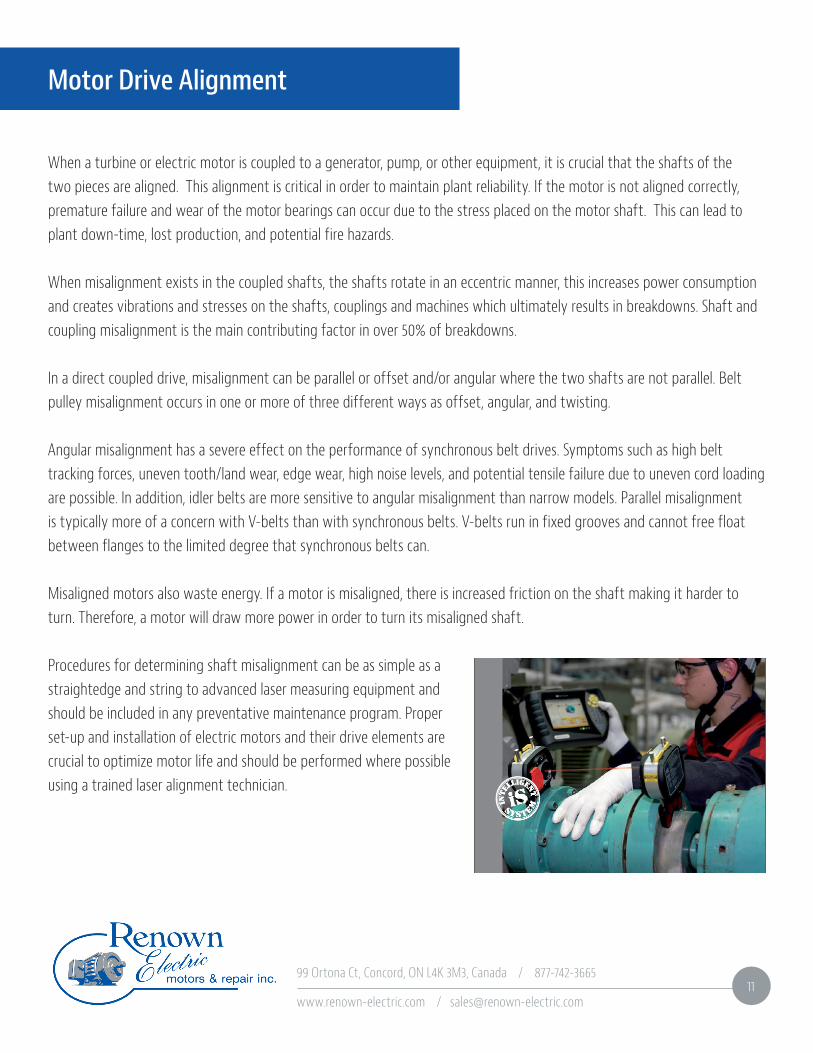
When a turbine or electric motor is coupled to a generator, pump, or other equipment, it is crucial that the shafts of the two pieces are aligned. This alignment is critical in order to maintain plant reliability. If the motor is not aligned correctly, premature failure and wear of the motor bearings can occur due to the stress placed on the motor shaft. This can lead to plant down-time, lost production, and potential fire hazards. When misalignment exists in the coupled shafts, the shafts rotate in an eccentric manner, this increases power consumption and creates vibrations and stresses on the shafts, couplings and machines which ultimately results in breakdowns. Shaft and coupling misalignment is the main contributing factor in over 50% of breakdowns. In a direct coupled drive, misalignment can be parallel or offset and/or angular where the two shafts are not parallel. Belt pulley misalignment occurs in one or more of three different ways as offset, angular, and twisting.
Angular misalignment has a severe effect on the performance of synchronous belt drives. Symptoms such as high belt tracking forces, uneven tooth/land wear, edge wear, high noise levels, and potential tensile failure due to uneven cord loading are possible. In addition, idler belts are more sensitive to angular misalignment than narrow models. Parallel misalignment is typically more of a concern with V-belts than with synchronous belts. V-belts run in fixed grooves and cannot free float between flanges to the limited degree that synchronous belts can.
Misaligned motors also waste energy. If a motor is misaligned, there is increased friction on the shaft making it harder to turn. Therefore, a motor will draw more power in order to turn its misaligned shaft.
Procedures for determining shaft misalignment can be as simple as a straightedge and string to advanced laser measuring equipment and should be included in any preventative maintenance program. Proper set-up and installation of electric motors and their drive elements are crucial to optimize motor life and should be performed where possible using a trained laser alignment technician.
Motor Drive Alignment

99 Ortona Ct, Concord, ON L4K 3M3, Canada / 877-742-3665
www.renown-electric.com / [email protected]
Winding Analysis
Electrical motor winding analysis (MWA) discovers early-stage problems in electrical equipment, allowing repairs during planned downtimes. This reduces costly unscheduled shutdowns and can reduce repair costs associated with catastrophic failures. This testing is nondestructive and can be used for motors, generators, transformers, and many other types of windings.
A breakdown of electric winding insulation is determined by motor current analysis, which helps the predictive maintenance professionals to know about the early failure of a potential problem. MWA helps you to reduce motor failures preventing lost production and increased maintenance costs. It is a good method for detecting problems with motor windings that can cause motor failure and a good tool for monitoring the dielectric strength of winding insulation. Therefore it is an essential component for the predictive maintenance of electric motors. Winding Analysis is a critical component for Predictive/Preventative Maintenance and motor programs.
Motor winding analyses (MWA) consists of three important tests of motor winding insulation. • Electrom TIG 12-D is a safe non-destructive test that uses DC voltage with any leakage viewed in micro-amps. • Off-line tests using a 1-Minute Megger Test, Hipot Test, and surge test are also part of this testing. • On-line tests that measure Voltage/Amps per phase and rotor bar tests.
Winding analysis can be performed in your facility when the equipment is not in operation. Motors can be tested at the motor control or motor connection box. This testing can be applied to AC or DC Motors and synchronous motors.
99 Ortona Ct, Concord, ON L4K 3M3, Canada / 877-742-3665
www.renown-electric.com / [email protected]
Onsite Balancing
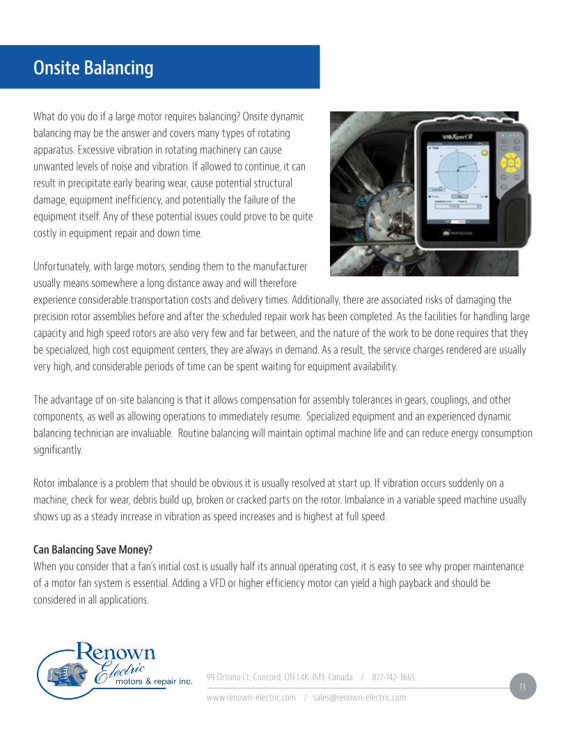
What do you do if a large motor requires balancing? Onsite dynamic balancing may be the answer and covers many types of rotating apparatus. Excessive vibration in rotating machinery can cause unwanted levels of noise and vibration. If allowed to continue, it can result in precipitate early bearing wear, cause potential structural damage, equipment inefficiency, and potentially the failure of the equipment itself. Any of these potential issues could prove to be quite costly in equipment repair and down time.
Unfortunately, with large motors, sending them to the manufacturer usually means somewhere a long distance away and will therefore experience considerable transportation costs and delivery times. Additionally, there are associated risks of damaging the precision rotor assemblies before and after the scheduled repair work has been completed. As the facilities for handling large capacity and high speed rotors are also very few and far between, and the nature of the work to be done requires that they be specialized, high cost equipment centers, they are always in demand. As a result, the service charges rendered are usually very high, and considerable periods of time can be spent waiting for equipment availability.
The advantage of on-site balancing is that it allows compensation for assembly tolerances in gears, couplings, and other components, as well as allowing operations to immediately resume. Specialized equipment and an experienced dynamic balancing technician are invaluable. Routine balancing will maintain optimal machine life and can reduce energy consumption significantly. Rotor imbalance is a problem that should be obvious it is usually resolved at start up. If vibration occurs suddenly on a machine, check for wear, debris build up, broken or cracked parts on the rotor. Imbalance in a variable speed machine usually shows up as a steady increase in vibration as speed increases and is highest at full speed.
Can Balancing Save Money?When you consider that a fan’s initial cost is usually half its annual operating cost, it is easy to see why proper maintenance of a motor fan system is essential. Adding a VFD or higher efficiency motor can yield a high payback and should be considered in all applications.

99 Ortona Ct, Concord, ON L4K 3M3, Canada / 877-742-3665
www.renown-electric.com / [email protected]
Oil Analysis
Oil analysis involves sampling and analyzing oil for various properties and materials that indicate wear and contamination in an electric motor or drive system. Taking samples and performing sample analysis on a regular basis creates a baseline of normal wear and can indicate when abnormal wear or contamination occurs.
Oil analysis is a story about how the equipment was used and its condition. Oil that has been inside any rotating machine for a period time gives an accurate condition of that motor. When moving parts are in contact, wear occurs and introduces microscopic metal particles to the oil. These particles are so small that they remain suspended in the oil. Many products of the facilities process are also trapped in the circulating oil as well as internal contamination. Classifying and measuring this contamination reveal the rate of wear and level of contamination. Therefore, the oil becomes a working history of the machine. A good oil analysis also proposes methods to reduce accelerated wear and contamination.
Oil samples should be taken on a regular basis as part of a preventative maintenance program and should only be taken after the lubricating system or component has been operated for a period long enough to attain operating temperature. This will make certain that the oil has been thoroughly circulated and will result in an oil sample that represents the oil in the system. The oil sample should always be taken from the same point.
A specific example would be checking for oxidation, which is a measure of gums, varnishes and oxidation products. High oxidation from oil that became too hot or were used too long can leave sludge and varnish deposits and thicken the oil. The easiest time to obtain a sample may be when the oil is being drained for an oil change. Sampling at this time usually involves letting some of the oil drain and then catching a sample in an appropriate container. Another test is viscosity. This is a measure of an oils resistance to flow. Oil may thin due to shear in multi-viscosity oils or may thicken from oxidation if it is run too long or too hot. Routine oil sampling is an easy and effective measure that can be used to monitor machine health with minimum cost and yield exceptional results.

99 Ortona Ct, Concord, ON L4K 3M3, Canada / 877-742-3665
www.renown-electric.com / [email protected]
Practical PM Procedures
Here are some guidelines that you can use to create a practical preventative program. • Lubricate regularly according to manufacturer’s instructions. On sleeve-bearing and other oil-lubricated machines, check oil reservoirs of fixed periodic intervals. In poor environments, change oil more frequently. Never over-lubricate; excess grease or oil can get into windings and deteriorate insulation. Be sure to use only the lubricant specified for the machine in question. However, you should also check into the possibility of using modern lubricants such as synthetics that have excellent life and lubricating qualities.
• Use graduated or calibrated grease guns during routine maintenance to ensure you know how much lubricants are being added or removed paying attention to the type and grade of lubricant for the application.
• Inspect bearings at predetermined intervals. Bearing failures are one of the most common causes of motor failures. Typical bearing problems include improper lubrication, misalignment of the motor with the load, replacement with the wrong type bearing, excessive loading, and harsh environments.
• On critical application motors or heavily used motors that have a frequent duty cycle, check bearings daily using a stethoscope or infrared scanner (or camera), if appropriate. Check bearing surface temperature with a thermometer, electronic temperature sensing devices, or stick-on temperature indicating labels. Compare temperature of hot bearings with the temperatures of normally operating bearings. Check oil rings and watch for excessive end play. • Check air gap between the rotor and stator with feeler gages at least annually. Measurements should be made at the top, bottom, and on both sides of the stator. Differences in readings obtained from year to year indicate bearing wear. • Check belt tension. Sheaves should be seated firmly with little or no play. Couplings should be tight, within tolerances, and should operate without excessive noise. An alignment check should be made on all motor-generator sets and on motor-load couplings when trouble is suspected.

99 Ortona Ct, Concord, ON L4K 3M3, Canada / 877-742-3665
www.renown-electric.com / [email protected]
• Inspect brushes and commutators of DC motors for excessive wear. Check brushes for proper type, hardness, conductivity, and fit in brush holders. Check holder spring pressure with a small scale. In most instances, pressure should be 2 to 2 1/2 lbs per sq in. of brush cross-sectional area depending on the application. If you do not know the proper spring pressure, contact your motor manufacturer or motor service repair center for actual pressure requirements for each motor. Call the manufacturer or servicing company to solve recurring problems of brush chatter, excessive brush wear, and sparking, streaking, or threading of commutator.
• Inspect motor mounts, mounting bolts, steel base plates for possible warping, and concrete base for cracking or other defects. • Perform vibration analysis tests. Excessive vibration may be hard to detect by hand, but it could be enough to shorten motor life significantly. It can cause bearing failure, metal fatigue of parts, or failure of windings. The cause of vibration is usually mechanical in nature, such as excessive belt tension, defective sleeve or ball bearings, misalignment, or improper balance. The most common cause is the unbalance of a rotating member (the motor rotor, rotating load, or other drive train component). Simple testing of the motor is done by uncoupling the load or removing the belts and then running the motor. Electrical problems also can cause vibration.
• Field vibration analysis can be accomplished by using a portable instrument that identifies vibrations and displays their amplitudes and frequencies.
• Restricted ventilation will cause a motor to operate at higher than preferred temperatures. Dirt, dust, and many other types of debris can clog ventilation passages of an open-frame motor.
• Open drip proof and completely enclosed motors are protected but must not be installed where air flow will be restricted or where there are excessive ambient temperatures. In high-temperature locations, consider the use of energy-efficient motors that operate at lower temperatures than standard motors. Extreme ambient temperatures will shorten motor life. • Perform insulation-resistance (IR) and other appropriate tests. Important motors should also receive a thorough visual inspection, as well as voltage and current checks. All values should be recorded and compared each year. The trend of the readings will indicate the condition of the motor and offer a guide to its reliability.
Practical PM Procedures (cont.)

99 Ortona Ct, Concord, ON L4K 3M3, Canada / 877-742-3665
www.renown-electric.com / [email protected]
• In dirty environments, blow out dirt and debris weekly and in normal environments a quarterly or semi-annual cleaning should be adequate. Ensure that dust or contamination is kept off high-voltage equipment. This is important as dust may contain conducting materials that could form unwanted circuit paths, resulting in current leakage or possible grounds or short circuits.
• Moving parts should operate easily without too much friction. Check operation of contactors and relays by hand, feeling for any binding or sticking. Look for loose pins, bolts, or bearings. If the control is dirty, it should be wiped or blown clean.
• Check contacts for pitting and signs of overheating, such as discoloration of metal, blackened insulation, or smell. Be sure that contact pressure is sufficient and the same on all poles and verify with manufacturer’s specification. Be on the lookout for frayed flexible leads.
• On essential controls, perform contact-resistance tests with a low-resistance ohmmeter on a regular basis. Proper contact resistance should be about 50 micro-ohms. Record the readings for future comparisons. This will indicate trends in the condition of contacts. • Overload relays should receive a thorough inspection and cleaning. You also should check for proper setting. In general, maintenance requirements for these relays include checking that the rating or trip setting takes into account ambient temperature as well as the higher inrush currents of modern, energy-efficient motors. You also should verify that contacts are clean and free from oxidation and that the relay will operate dependably when needed. Relays should be tested and calibrated every one to three years.
• Finally, keep accurate records. This is extremely important as the key concept of maintenance is to be able to predict a trend. Data from subsequent tests is compared against previous data and determinations can be made for planned maintenance.
Practical PM Procedures (cont.)
99 Ortona Ct, Concord, ON L4K 3M3, Canada / 877-742-3665
www.renown-electric.com / [email protected]
Conclusion
Electric motor maintenance is a complex subject but with a properly implemented program costs can be significantly reduced in both parts and downtime. In many systems it is not just the motor that causes a failure. Many of the tests can be performed onsite again reducing costs. It’s worth considering so talk to a professional servicing company in order to make an educated decision. Sources: http://www.alltestpro.com/fileadmin/user_upload/PDFs/Test_methods_for_determing_the_impact_of_motor_condition_on_motor_efficiency.pdf
http://www.reliableplant.com/Read/22766/test-methods-motor-reliability
http://en-us.fluke.com/community/fluke-news-plus/understanding-the-benefits-of-vibration-monitoring-and-analysis.html?fnpk=Predictive%20Maintenance#fbid=hMD4TB9ouUx
http://en-us.fluke.com/community/fluke-news-plus/moving-from-reactive-to-predictive-maintenance.html?fnpk=Predictive%20Maintenance#fbid=hMD4TB9ouUx
http://www.copper.org/environment/sustainable-energy/electric-motors/case-studies/a6150.html
http://www.pump-zone.com/topics/instrumentationcontrols/predictive-preventive-maintenance
http://www.reliableplant.com/Read/12495/preventive-predictive-maintenance
Infrared Inspection: http://www.midwestinfrared.com/benefit.htm
http://www.palmettoinfrared.com/benefits-of-infrared-inspection/
http://bradyinfrared.com/infrared-thermographys-economic-benefits/
http://www.goldeneagleenvironmental.com/resources/benefits-infrared.php
http://www.insightenergy.ca/infrared-thermal-imaging.html
Vibration Analysis: http://www.artecmachine.com/_images/documents/vibration_analysis_for_gears.pdf
http://en-us.fluke.com/community/fluke-news-plus/understanding-the-benefits-of-vibration-monitoring-andanalysis.html?fnpk=Predictive%20Maintenance#fbid=Jx1Lamk5p6U
http://mdiag.com/vibration-analysis.php
http://www.plant-maintenance.com/maintenance_articles_vibration.shtml
http://www.davis.com/Assets/MoreInfo/Fluke_Benefits_of_Vibration_Testing_Webinar%20.pdf
99 Ortona Ct, Concord, ON L4K 3M3, Canada / 877-742-3665
www.renown-electric.com / [email protected]
Conclusion (cont.)
Alignment: http://en.wikipedia.org/wiki/Shaft_alignment
http://www.techtransfer.com/resources/wiki/entry/2696/
http://www.pump-zone.com/topics/motors/pump-alignment-just-facts
http://www.pruftechnik.com/alignment-systems/machine-alignment/effects-of-misalignment.html?no_cache=1
http://www.pruftechnik.com/alignment-systems/machine-alignment/benefits.html?no_cache=1
Winding Analysis: http://ecmweb.com/content/true-benefits-motor-circuit-analysis
http://www.lselectric.com/electrical-winding-analysis/
http://www.lselectric.com/what-role-does-motor-winding-analysis-play-in-predictive-maintenance/
http://www.reliableplant.com/Read/10686/motor-circuit-analysis
http://www.alltestpro.com/technology-overview/
Onsite Balancing: http://www.lselectric.com/on-site-dynamic-balancing/
http://www.aemsltd.co.uk/balancing.html
http://www.irdbalancing.com/downloads/On%20Site%20Maintenance%20of%20Strategic%20Rotating%20Machines%20%20-%20May%202009.pdf
Oil Analysis: http://grounds-mag.com/mag/grounds_maintenance_benefits_oil_analysis/
http://www.machinerylubrication.com/Read/29004/oil-analysis-benefits
https://www.checkfluid.com/pages.php?CDpath=3_37
http://www.machinerylubrication.com/Read/30/oil-analysis-benefits
http://oil-analysis.testoil.com/?p=297


![ROSTA Anti-vibration Mounts - Transmissioner | Jens-S · ROSTA Anti- vibration Mounts ... Art. No. Type Natural frequency Gmni. – Gmax. [Hz] O P x max. Material structure (zinc-plated](https://img.dokumen.tips/doc/110x75/5c86c68009d3f29b298ce3e1/rosta-anti-vibration-mounts-transmissioner-jens-s-rosta-anti-vibration.jpg)