Embed Size (px)
Citation preview

1
PRESTRESSED CONCRETE STRUCTURES
Amlan K. Sengupta, PhD PE
Department of Civil Engineering
Indian Institute of Technology Madras
Module – 3: Analysis of Members
Lecture – 12: Analysis of Members under Flexure (Analysis at Service Loads)
Welcome back to prestressed concrete structures. This is the second lecture of module on
analysis of members.
(Refer Slide Time: 01:15)
Today, we are starting the analysis of members under flexure. We shall learn the analysis
at service loads based on three concepts. The first one is based on stress concept. Next,
based on force concept and finally we shall learn the analysis based on load balancing
concept.
Analysis of members under flexure:

2
(Refer Slide Time: 01:50)
Last time, we studied the analysis of members under axial load. Similar, to members
under axial load, the analysis of members under flexure refers to the evaluation of the
following. First is the permissible prestress based on allowable stresses at transfer;
second are the stresses under service loads. These are compared with allowable stresses
under service conditions.
(Refer Slide Time: 02:23)
3
Third is the ultimate strength. This is compared with the demand under factored loads;
and fourth is the entire load versus deformation behavior.
To summarise, what do we mean by analysis for prestressed concrete members? The first
one is the analysis at transfer. Based on the permissible stresses at transfer, we can
determine how much prestressing force we can apply, and what the maximum limit of the
prestressing force is. Next, is the analysis at the service load stage, where we find the
stresses due to the prestressing force and the service loads, and we need to make sure that
the stresses are within the allowable values for service conditions. Third, we find out the
ultimate strength and this is compared with the demand under factored loads. Finally, we
may study the load versus deformation behavior which is the entire curve. This behavior
gives an idea as to how a member deforms with the increasing load.
In this lecture, we shall cover the analysis under service loads and at transfer. Both these
are of similar type. These are based on elastic analysis. In our next few lectures, we shall
study the analysis at ultimate, and we shall briefly touch upon the load versus
deformation behaviour. The load versus deformation behaviour for a member under
flexure is determined based on the moment versus rotation curve. We shall not go into the
details of it. We shall discuss it to understand the behaviour of prestressed concrete
members. Thus, the analysis at transfer under service loads and factored loads will be
presented separately. The evaluation of the loads versus deformation behaviour will also
be covered in the next presentation.
4
(Refer Slide Time: 04:54)
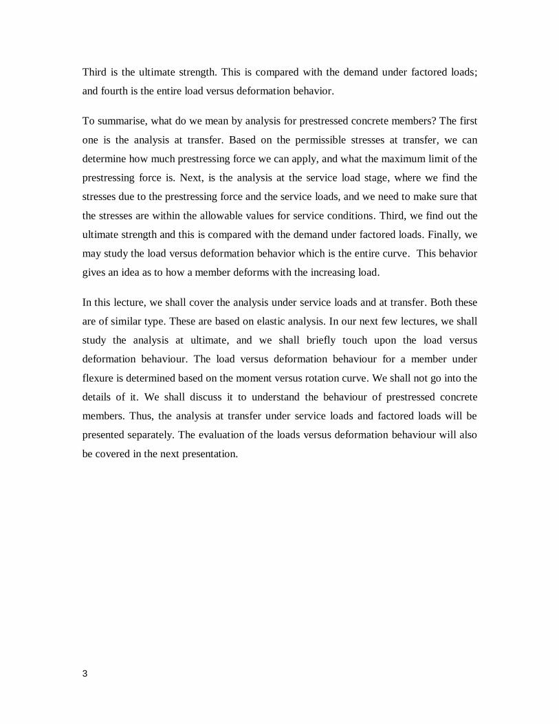
The assumptions of analysis of members under flexure, considers the following. First,
plane sections remain plane till failure. This is the basic assumption of beams under
flexure and this is known as the Bernoulli’s hypothesis. Based on this, we draw the strain
diagram, which is linear across the depth of a section at any instance of the complete load
versus deformation behaviour. That means, we consider that the assumption is valid till
the failure of the member.
The second assumption is, perfect bond between concrete and prestressing steel for
bonded tendons. For pre-tensioned members and for post-tensioned members which are
grouted, we assume a perfect bond between the concrete and the steel which means there
is strain compatibility between these two materials. The strain in the concrete at the level
of the steel is equal to the change in the strain in the prestressing tendons. Earlier, we had
seen that we can express this strain condition in terms of the strains in the two materials.

5
(Refer Slide Time: 06:32)
We also use the principles of mechanics. There are three principles of mechanics
involved in the analysis. First is the equilibrium of internal forces with the external loads.
The compression in concrete which will be represented as C, is equal to the tension in the
tendon which will be represented as T. The second is, the couple of C and T is equal to
the moment due to the external loads. This is the moment equilibrium equation.
(Refer Slide Time: 07:20)

6
The compatibility of the strains in concrete and in steel for bonded tendons is the second
principle that we use. The formulation also involves the first assumption of plane sections
remaining plane after bending. That means we are able to relate the strain in the
prestressing tendon with the strain in the extreme compressive fibre of the concrete. So,
there are two assumptions here. One is, plane sections remaining plane which gives us the
strain distribution across the depth and the second assumption is, the strain compatibility
between the concrete and the steel at the level of the steel. With these two assumptions,
we are able to relate the strain in the prestressing tendon with the strain in the concrete at
the extreme compression fibre, and this gives us the compatibility equation. For
unbonded tendons, the compatibility is in terms of the deformation. It is not in terms of
the strain at a particular point, but it is in terms of the deformation of the overall member.
The third principle is the constitutive relationships, which relate the stresses and strains in
the materials. Last time, we had seen the variations of the stresses and strains in concrete,
the prestressing steel and the non-prestressed reinforcement, if there is any. We can
express these variations in terms of equations. These equations are called the constitutive
relationships for the materials.
(Refer Slide Time: 09:21)

7
The one interesting feature of prestressed concrete which makes it different from
reinforced concrete is the variation of the internal forces. In reinforced concrete members
under flexure, the values of compression in concrete and tension in the steel increase with
increasing external load. The change in the lever arm which is represented as z is not
large. In reinforced concrete, when we increase the load, both the values of C and T
increase; whereas, the lever arm between C and T does not increase appreciably. It stays
more or less the same value.
(Refer Slide Time: 10:11)
In prestressed concrete members under flexure, at transfer of prestress, C is located close
to T. That means, after the prestress has been transferred, the compression and tension
are almost at the same location. The couple of C and T may balance only the self-weight.
There may be a slight lever arm between them, which is to balance the self-weight of the
member. But at service loads, as the load is increased from the self-weight, C shifts up
and the lever arm z gets large. The variation of C or T is not appreciable. Unlike
reinforced concrete, in prestressed concrete as the load increases, the values of C and T
do not change appreciably within the service load range. It is the lever arm z which
changes appreciably.

8
The following figure explains this difference schematically for a simply supported beam
under uniform load.
(Refer Slide Time: 11:27)
On the left side, we see a reinforced concrete beam with a small load say w1. C1 is equal
to T1 and the lever arm between them is z1. The lever arm multiplied by either C1 or T1
gives the moment at that particular section. Once the load is increased from w1 to w2, we
find that, z1 is almost close to z2 but, C2 has increased from C1. T2 has increased from T1.
That means, in reinforced concrete members, the forces increase, whereas, the lever arm
does not increase appreciably.
On the right hand side, for a prestressed member for a small load w1, there is a small
lever arm between the compression and the tension. As the load is increased to w2, the
lever arm has increased, whereas, the forces have not changed much. That means C2 is
almost equal to C1. Similarly, T2 is almost equal to T1 whereas z2 is appreciably larger
from z1. This is a unique difference between the reinforced concrete and the prestressed
concrete members.
To summarize, in a reinforced concrete member, the forces in the concrete and in the
steel increase with increasing load; the lever arm does not change appreciably. Whereas,

9
in prestressed concrete members, the forces C and T do not increase much up to the
service loads, whereas, the lever arm increases as the load is increased.
(Refer Slide Time: 13:38)
The analyses at transfer and under service loads are similar. The methods are explained
only for the service loads, because the only difference is, at transfer, the moment acting is
due to the self-weight; whereas, at service loads, the moment is due to the self- weight
plus the superimposed, dead load and live load. Otherwise, the analysis for both the
stages are similar, it is based on the elastic analysis. Hence, only the analysis for service
loads is being shown here. For the analysis for transfer, we just need to substitute the
moment due to self-weight in place of the moment due to service loads.
A prestressed member usually remains uncracked under service loads. This helps us in
our analysis. We take advantage of the full cross-section.
We assume, that the concrete and steel are treated as elastic materials. The principle of
superposition is applied, and the increase in stress in the tendon due to bending is
neglected. These assumptions are basic for a prestressed concrete member. We calculate
the sectional properties for full cross-section and we do not consider any increase of the
stress in the tendon due to the increase in the load within the service range.

10
Next, we will learn the approaches of analysis of members under flexure for service
loads.
(Refer Slide Time: 15:54)
We know that there are three approaches to analyse a prestressed concrete member at
service loads. First is based on the stress concept. Second is based on the force concept,
and third is based on the load balancing concept. The following material explains the
three concepts.
First, we are studying about the analysis based on the stress concept.

11
(Refer Slide Time: 16:30)
In this approach, the stresses at the edges of the section under the internal forces in
concrete, are calculated. The stress concept is used to compare the calculated stresses
with the allowable stresses. One of the primary purposes of analyses of members under
service loads is to find out the stresses in concrete in the extreme fibers. For this purpose,
we take an approach which is based on calculating the stresses in the concrete depending
on the compression that acts in the concrete. We directly calculate the stresses and we
compare the stresses in the extreme fibers with the allowable stresses under service
conditions. This approach is based on calculating the stresses directly.

12
(Refer Slide Time: 17:42)
The following figure shows the stresses in a simply supported beam under a uniformly
distributed load and prestressed with constant eccentricity along its length. We are
considering a beam, which is simply supported under a uniformly distributed load. For
simplicity, the centroid of the steel is considered to be at constant eccentricity throughout
the length of the member.
(Refer Slide Time: 18:12)

13
For this beam, the stress diagrams at a particular section are as follows. At any particular
section, we are identifying the internal forces that are acting in the concrete. First is the
prestressing force which is being transferred by the tendon to the concrete and it is
compressive. The second is the moment which is acting due to the weight of the beam.
Remember that at service loads, M includes the moment due to self-weight and that due
to the service loads.
Once, we have identified the internal forces acting in the concrete, next, we are finding
out the stresses due to these forces. The first one is a uniform compressive force that is
generated by the prestressing force. This is represented as ‒ P/A. That means the first
component is a uniform compressive force due to the prestressing force applied by the
tendon.
The second one is a varying stress due to the eccentricity of the prestressing force from
the centroid of the concrete section. This varying stress is given by the flexure equation
which is ± Pey/I. P.e is the moment of the prestressing force about the CGC, y is the
distance at any point in the section from the CGC, I is the moment of inertia of the cross-
section. Note, that the stress is compressive at the bottom when the CGS is below the
CGC and this stress is considered to be negative; whereas, the stress above the CGC is
tensile, which is denoted as positive. That means when the CGS is located below the
CGC, the stress due to the moment of the prestressing force is compressive at the bottom
and tensile at the top.
The third component is the stress due to the external moment M. Here also the stress is
given as moment times the distance from the CGC divided by the moment of inertia I.
For this moment, the stress at the bottom is tensile and the stress at the top is
compressive. Note the difference between the stresses created by the moment of the
prestressing force and the moment due to external loads. For the moment due to
prestressing force, the stress is tensile at the top and compressive at the bottom, whereas,
for the moment due to external loads, the stress is compressive at the top and tensile at
the bottom.
14
Once we have these three components of the stresses by the principle of superposition,
we can add them up and get the resultant stress profile about the section.
If a section is designed as a Type 1 member then there will be a resultant compression
throughout the depth of the section at any location of the beam, and the stress profile will
appear something like this on the right. There will be a higher compression at the top and
a lower compression at the bottom. If we design the section for a Type 2 member then,
there can be tensile stress under the characteristic service loads at the bottom and if we
design a member as a Type 3 member then, there will be tensile stress at the bottom as
well as cracking under the characteristic service loads.
(Refer Slide Time: 23:42)
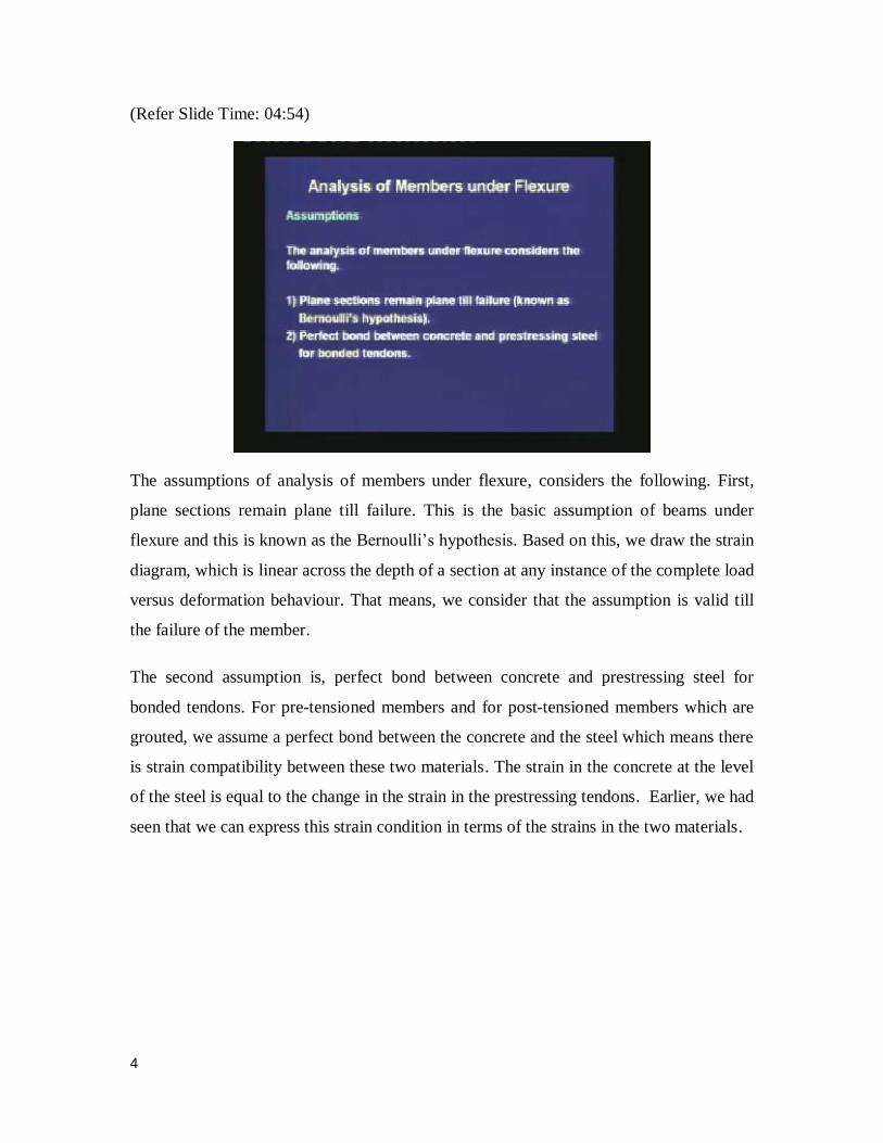
Once we have identified the stress components due to the forces in the concrete which are
P and M, we can write an expression of the stress in the concrete for any depth in the
section, and at any location in the beam. This expression is equal to ‒ P/A ± Pey/I ±
My/I. We shall use this expression frequently to check the stresses in concrete under
service loads.
The second concept is based on the force concept.

15
(Refer Slide Time: 24:54)
This approach is analogous to the study of reinforced concrete. The tension in
prestressing steel and the resultant compression in concrete are considered to balance the
external loads. In this concept, we are not calculating the stresses directly. We are more
interested in the forces that are generated in the concrete and in the prestressing tendon,
and we write the equilibrium equation in terms of the forces. The first equilibrium is, the
axial force equilibrium, C is equal to T. The second equilibrium is the moment
equilibrium equation, where C or T times the lever arm is equal to the moment due to the
external loads. The force concept is used to determine the dimensions of a section and to
check the service load capacity.

16
(Refer Slide Time: 26:27)
If we calculate the stresses based on this approach then they will come out to be same as
those calculated based on the stress concept. The final results of the stresses based on the
stress concept or based on the force concept, are the same. Both the concepts will give the
same values of the stresses in the concrete. The stresses at the extreme edges are
compared with the allowable stresses under service conditions.
(Refer Slide Time: 27:01)

17
This figure shows the internal forces in the section. Right at prestressing, the compression
coincides with the tension if we are neglecting the self-weight. If there is some self-
weight then the compression will be slightly above the tension. At service loads after
loading, compression and the tension remain same almost, but the compression shifts
above tension. The lever arm that is generated helps in balancing the moment due to the
external loads. We are designating the eccentricity of the tension, which is same as the
eccentricity of the prestressing tendon, by e. We are designating the eccentricity of the
compression from the CGC by the symbol ec. Here we are having two eccentricities: one
is the eccentricity of the tension which is represented as e, and the second is the
eccentricity of the compression which is represented as ec.
(Refer Slide Time: 28:21)
The equilibrium equations are: the first one is C = T, which is the force equilibrium
equation along the axis of the member. The second equilibrium equation is M = Cz, or it
can be written as Tz, and z is the sum of the eccentricities of the tension and the
compression. We can write M = C(ec + e). This is the equation which relates the moment
due to external loads with the moment that is generated by the internal forces.

18
(Refer Slide Time: 29:09)
The resultant stress at a point in concrete is given by the following equation. When we
are trying to find out the stress in the concrete, we are interested only in the compression
that acts in the concrete. Remember that, T acts in the tendon, whereas, C acts in the
concrete. We are calculating the position of C at service loads, which is given by the
eccentricity ec. Then the stress due to C in the concrete is given as ‒ C/A ± Cec y/I. Here,
under service loads since C is above the CGC, it creates compression at the top. For any
region above CGC, we shall take negative value in the expression and for any region
below the CGC we shall take a positive value, which means a tension due to the moment
of C above CGC. The expression that we had seen based on the stress concept and the
expression that we have seen based on the force concept, both give the same values of a
stress.
19
(Refer Slide Time: 30:47)
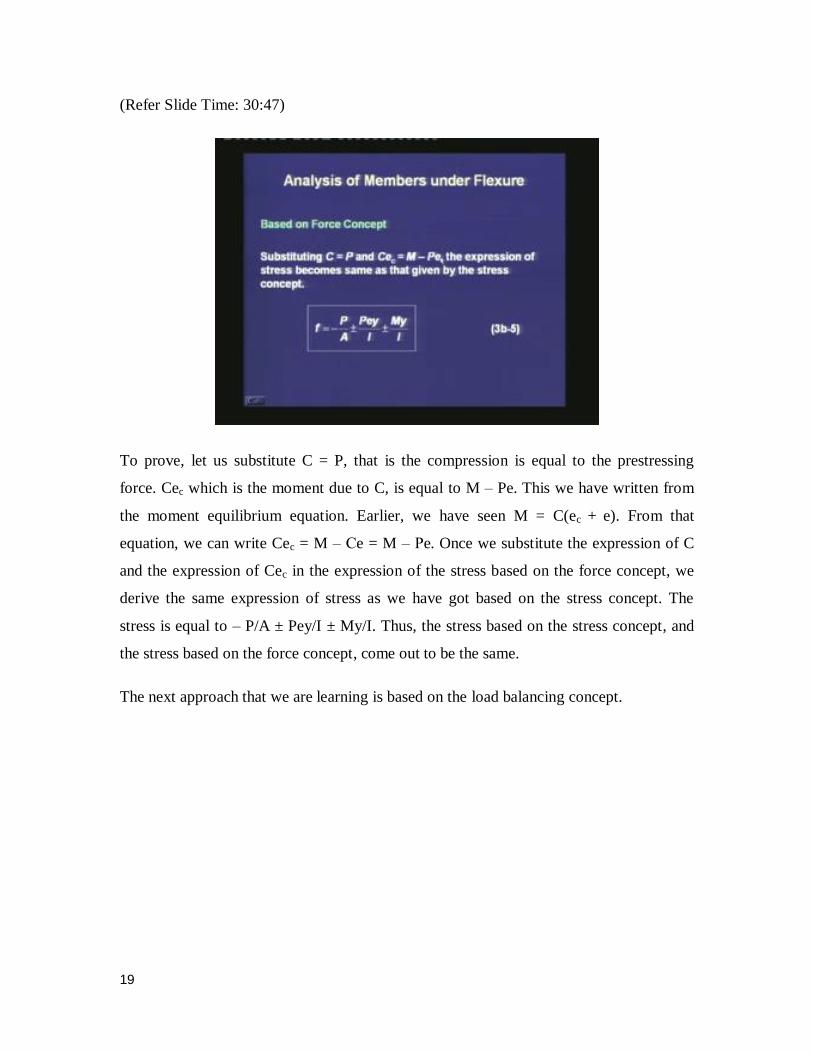
To prove, let us substitute C = P, that is the compression is equal to the prestressing
force. Cec which is the moment due to C, is equal to M ‒ Pe. This we have written from
the moment equilibrium equation. Earlier, we have seen M = C(ec + e). From that
equation, we can write Cec = M ‒ Ce = M ‒ Pe. Once we substitute the expression of C
and the expression of Cec in the expression of the stress based on the force concept, we
derive the same expression of stress as we have got based on the stress concept. The
stress is equal to ‒ P/A ± Pey/I ± My/I. Thus, the stress based on the stress concept, and
the stress based on the force concept, come out to be the same.
The next approach that we are learning is based on the load balancing concept.

20
(Refer Slide Time: 32:17)
This is a very unique concept for prestressed concrete members. This approach is used
for a member with curved or harped tendons, and in the analysis of indeterminate
continuous beams. The moment, upward thrust and upward deflection are calculated. The
upward thrust balances part of the superimposed load. This approach is thus termed as the
load balancing concept.
We calculate the moment that is generated by the prestressing force within the section.
We calculate the upward thrust that is generated in the section due to the curved profile of
the tendon. Also, we calculate the upward deflection which is the camber due to the
upward thrust. The expressions for three profiles of tendons in simply supported beams,
are shown.

21
(Refer Slide Time: 33:49)
For a parabolic tendon, we are drawing the free body diagram of concrete. The tendons
apply a prestressing force at an inclination at the ends, at the anchorage locations. Since
the tendon is curved, there is an upward reaction from the tendon on to the concrete. This
is called the upward thrust, and is represented as wup. This upward load wup is constant
for a parabolic tendon. If we are interested in the bending moment diagram due to this
upward thrust, then it is similar to a simply supported beam with a uniformly distributed
load. It is a parabolic moment diagram.

22
(Refer Slide Time: 35:01)
The moment at the centre due to the uniform upward thrust wup is given by the equation,
M = wup L2/8. This expression is same as what we have learnt in our structural analysis of
simply supported beams under uniformly distributed load. The only difference is that the
sign of the moment is different. Here, the moment is considered to be negative since the
beam is lifting up, whereas, for a conventional simply supported beam, the moment is
considered to be positive, since the beam sags down.
The moment at the centre from the prestressing force is given as M = Pe. We had seen
earlier, based on the forces in the section, that whenever the P is acting at an eccentricity
with the CGC, there is a moment due to P and this moment is given as Pe. The expression
of the moment that we have calculated based on the upward thrust, and the expression of
the moment that comes from the eccentricity of the prestressing force can be equated, and
we can find out the expression of the upward thrust. The expression of wup is calculated
by equating the two expressions of M. M = wup L2/8 = Pe. Therefore, wup = 8Pe/L
2.

23
(Refer Slide Time: 36:46)
The upward deflection Δ is calculated from wup based on elastic analysis. The expression
is Δ = 5wupL4/384EI. This we have got from the analysis of a beam under uniformly
distributed load. Here, the uniformly distributed load is upwards which is represented as
wup. Hence, the deflection is also upwards which is known as camber due to prestressing.
The camber is given as 5wupL4/384EI. Here, E is the modulus of concrete and I is the
moment of inertia.

24
(Refer Slide Time: 38:07)
Next, we are learning the load balancing concept for singly harped tendon. For a singly
harped tendon, there is one bend at the centre and at that bend, since the tendon wants to
straighten out, it applies a reaction in the concrete which is a single load acting upwards.
The moment diagram which we can draw from the free body diagram of the concrete is
triangular shaped. It is similar to the moment diagram of a simply supported beam under
a central point load. The only difference is, here the moment is hogging because the beam
tries to bend upwards.

25
(Refer Slide Time: 39:02)
There are two expressions of the moment: one based on the central point load where M =
Wup L/4 and the second is, M = Pe. Once we equate these two expressions of M, we get
an expression of Wup which is equal to 4Pe/L. We can calculate the upward deflection or
the camber from the structural analysis formula. Δ = WupL3/48EI where, E is the modulus
of concrete.
(Refer Slide Time: 40:00)

26
Next, is the load balancing concept for a doubly harped tendon. Here, there are two hold
down points which are symmetrically placed and the distance of one harping point is
represented as aL. Since the harping points are symmetric, the upward loads at these two
points are also same. The moment diagram has a linearly increasing part at the two ends
and a constant value in between the two harping points. This is similar to beams tested
under two point loading, where we have a constant moment region at the centre.
(Refer Slide Time: 40:54)
If we equate the two expressions of M, M = WupaL which is derived from the moment
diagram, and M = Pe. Then, we get an expression of Wup which is equal to Pe/aL. From
structural analysis, we can find out the upward deflection Δ = a(3 ‒ 4a2) Wup L
3 / 24EI.
Thus, we have seen the load balancing concept for three types of curved tendons. First,
we had seen that for a parabolic tendon, the upward thrust is a uniformly distributed load
acting upwards. For a singly harped section, the upward thrust is a single point load and
for a doubly harped section, the upward thrust is two point loads acting at the two harping
points. We have been able to calculate the expressions of the upward thrust, and the
deflections due to the upward thrust.

27
(Refer Slide Time: 42:35)
Next, we are solving a problem. A concrete beam prestressed with a parabolic tendon is
shown in the figure. The prestressing force applied is 1620 kN. The uniformly distributed
load of 45 kN/m includes the self-weight. Compute the extreme fibre stress at the mid-
span by applying the three concepts. Draw the stress distribution across the section at
mid-span.
Here, the beam is a simply supported beam with a parabolic tendon. If we see the
sections, at the end the CGS is located at the CGC. At the centre, the CGS is at an
eccentricity of 145 mm from the CGC. The span of the beam is 7.3 meters.
28
(Refer Slide Time: 43:53)
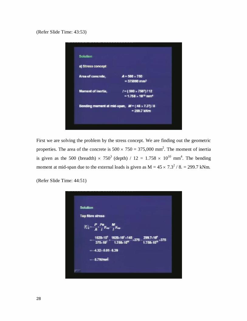
First we are solving the problem by the stress concept. We are finding out the geometric
properties. The area of the concrete is 500 750 = 375,000 mm2. The moment of inertia
is given as the 500 (breadth) 7503
(depth) / 12 = 1.758 1010
mm4. The bending
moment at mid-span due to the external loads is given as M = 45 7.32 / 8. = 299.7 kNm.
(Refer Slide Time: 44:51)

29
Based on the stress concept, the top fibre stress is given as (fc)t = ‒ P/A + Peytop/I
‒ Mytop/I. Remember that, the stress due to the eccentricity of the prestressing
force is positive at the top, whereas, the stress due to the external moment is
negative at the top, and accordingly we have selected the sign. Once we substitute
the values of the prestressing force, its eccentricity at the center and the values of
the moment, A, I and ytop, we get the stress at the top which is ‒ 5.7 N/mm2.
(Refer Slide Time: 46:04)
Second, we are calculating the bottom fibre stress with a similar expression, except
the sign for the moment due to the prestressing force is now negative because it
creates compression at the bottom, and the sign for the external moment is positive
because it creates tension at the bottom for the simply supported beam. Once, we
substitute the values of the variables, we get the stress at the bottom to be ‒ 2.9
N/mm2. Note, that the compressive stress at the bottom is numerically lower than the
compressive stress at the top.

30
(Refer Slide Time: 46:51)
The same calculations, we are doing based on the force concept. Here the applied
moment is equal to 299.7 kNm. Hence, the lever arm z is given by M / P which is 299.7
106 (in Nmm) / 1620 10
3 (in N) = 185 mm. At the center, the deviation of the
compression from the CGS is equal to 185 mm, and that is the lever arm generated when
the external load is applied on the member.
The eccentricity of the compression or the pressure line is given as ec = z ‒ e = 185 ‒ 145
= 40 mm. That is, the compression is acting at a distance of 40 mm above the CGC. The
eccentricity of the prestressing force is 145 mm below the CGC, whereas, the eccentricity
of the compressive force is 40 mm above the CGC.
31
(Refer Slide Time: 48:36)
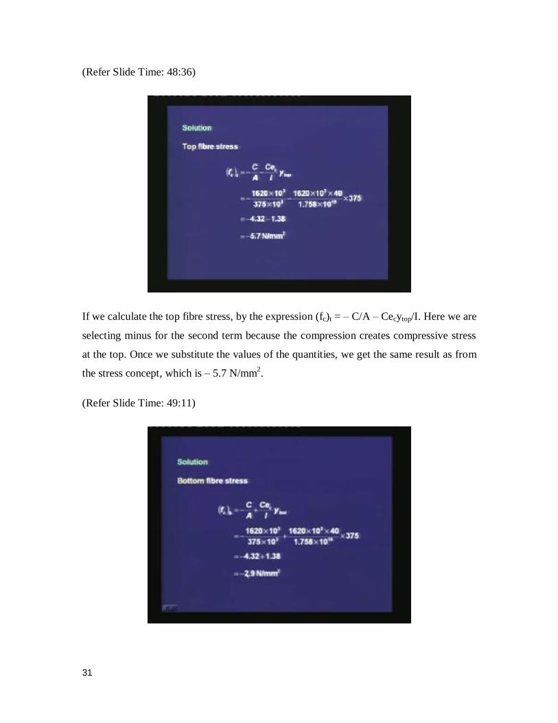
If we calculate the top fibre stress, by the expression (fc)t = ‒ C/A ‒ Cecytop/I. Here we are
selecting minus for the second term because the compression creates compressive stress
at the top. Once we substitute the values of the quantities, we get the same result as from
the stress concept, which is ‒ 5.7 N/mm2.
(Refer Slide Time: 49:11)

32
If we calculate the bottom fibre stress, we are selecting positive for the second term
because the stress generated in the concrete by the compressive force is tensile, and we
are using the value of ybot. Once we substitute the values of the variables, we get the same
value as from the stress concept, which is equal to ‒ 2.9 N/mm2.
(Refer Slide Time: 49:52)
Based on the load balancing concept, first we are calculating the upward thrust which
is wup = 8 Pe/L2. Once we substitute the values of P, e and L, we get the upward load
to be 35.3 kN/m. Remember that, we were having an external load of 45 kN/m. Due
to the parabolic tendon and a prestressing force of 1620 kN, we have an upward thrust
of 35.3 kN/m. The residual downward load wres = 45 ‒ 35.3 = 9.7 kN/m. Hence, we
can see that by the load balancing concept, we are able to calculate the residual load
acting on the beam, which is equal to the actual load minus the upward thrust.

33
(Refer Slide Time: 51:14)
The residual bending moment is equal to Mres = wres L2/8 = 64.6 kNm. The residual
bending stress, which is the stress due to the residual bending moment, is equal to My/I.
Here once we substitute the values of the variables, we get a value of 1.38 N/mm2.
Hence, this is the bending stress which is created by the residual bending moment.
(Refer Slide Time: 51:52)
34
The total bottom fibre stress (fc)b = ‒ P/A ‒ (fc)res (minus because in the bottom we have a
compressive stress), and once we substitute the values, we get the same value as that by
the stress concept, which is ‒ 5.7 N/mm2. The top fibre stress is given as ‒ P/A + (fc)res =
‒ 2.9 N/mm2.
(Refer Slide Time: 52:57)
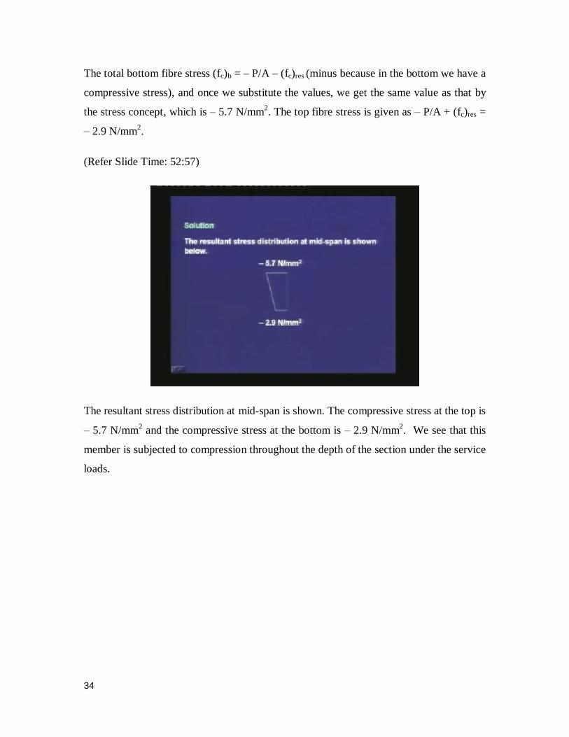
The resultant stress distribution at mid-span is shown. The compressive stress at the top is
‒ 5.7 N/mm2 and the compressive stress at the bottom is ‒ 2.9 N/mm
2. We see that this
member is subjected to compression throughout the depth of the section under the service
loads.

35
(Refer Slide Time: 53:32)
Thus, today we have studied the analysis of members under flexure. We first learnt that
we do analysis for several load stages. First, we do an analysis for transfer, for which we
calculate the stresses at the extreme fiber. Based on the allowable values, we can fix how
much prestress we can apply. Next, we do an analysis for the service loads where we
calculate the stresses under service loads, and made sure that the stresses are within the
allowable values for the service conditions. Subsequently, we do an analysis for the
ultimate strength, and a section should be adequate to sustain the maximum factored
loads in case of an extreme event. We may also do an analysis for the entire load versus
deflection behavior to understand the deformation of the member with increasing load.
In today’s lecture, we studied only the analysis at transfer and service loads. Both these
analyses are similar. They are elastic analyses. The only difference is that, at transfer the
moment is due to self-weight alone, whereas at service loads, the moment is due to the
self-weight plus the external load. Otherwise, the expression of the stresses is same for
the two cases. Hence, we had just studied the analysis for service loads knowing that the
analysis for transfer is similar.
The analysis for service loads can be done in three ways.
36
The first one is based on stress concept. We use this approach, when we are interested to
find out the stresses in the external fibers in the concrete.
The second approach is based on the force concept which is similar to the analysis of
reinforced concrete members, where we are interested to know the forces in the section
and the moment. For the force concept, we can write the equilibrium equation for the
axial forces, C = T and the equilibrium equation for the moment where M = either of C or
T times the lever arm. We can use the force concept to select the dimensions of the
members when we are designing a member. We can also find out what are the service
loads that can be applied on a prestressed member.
The third concept we studied was the load balancing concept, and this is applicable for a
curved tendon. When the prestressing force is applied in a curved tendon, the tendon
applies an upward thrust to the concrete member. This upward thrust balances part of the
externally applied load and hence, this method is called the load balancing concept. This
concept is mostly used in the study of continuous indeterminate beams, which we shall
see later.
Although, the approaches are different, the final results of the stresses will be the same.
First, we have seen this by deriving an analytical expression of the stress based on the
force concept, and we have seen that this expression is the same as that based on the
stress concept. We solved a problem of a simply supported beam with a parabolic tendon
subjected to a uniformly distributed load,where we calculated the stresses at the extreme
fibres at mid-span by the three concepts. We found that the values of the stresses are
same based on the three concepts. We have also observed that for a Type 1 member,
when there is compression throughout the section under service loads, the stress profile
will be such that there will be higher compression at the top and lower compression at the
bottom.
Thus, today we studied the analysis of members at service loads. In our next class, we
shall study some particular definitions for the analysis under service loads, and then we
shall move on to the analysis for ultimate strength. Thank you.

37


![lec12 [호환 모드] - Sangji Universitycompiler.sangji.ac.kr/lecture/java/2008_1/lec12.pdf · 2019. 2. 14. · Microsoft PowerPoint - lec12 [호환 모드] Author: Main Created](https://img.dokumen.tips/doc/110x75/60bbcfc76d94d3477c546d23/lec12-eeoe-sangji-2019-2-14-microsoft-powerpoint-lec12-.jpg)