Embed Size (px)
Citation preview

PRESTRESSED CONCRETE STRUCTURES
Amlan K. Sengupta, PhD PE
Department of Civil Engineering,
Indian Institute of Technology Madras
Module – 9: Special Topics
Lecture – 37: Two-way Slabs (Part 1)
Welcome back to prestressed concrete structures. This is the third lecture of Module 9 on
special topics. In this lecture, we shall study two-way slabs.
(Refer Slide Time: 01:37)
First, we shall introduce the different types of two-way slabs; next, we shall learn about
the analysis of two-way slabs. Then, we shall move on to the features in modelling and
analysis; what are the different aspects in the two-way slabs which are different from that
of one-way slabs and then, we shall move on to the distribution of moments to the strips
in the two-way slabs.

(Refer Slide Time: 02:00)
When a rectangular slab is supported on all the sides and the length-to-breadth ratio is
less than 2, it is considered to be a two-way slab. The slab spans in both the orthogonal
directions. For a one-way slab, we design the slab for only one direction and in the
transverse direction, we provide nominal reinforcement. But for a two-way slab, it has to
be designed for both the directions.
A circular slab or other types of rectangular slabs with different types of support
condition which do not fall in the category of one-way slab, are considered as two-way
slabs. Thus, a rectangular slab which is supported on three sides or two adjacent sides, are
also categorized under two-way slabs.

(Refer Slide Time: 03:11)
Rectangular two-way slabs can be divided into the following types.
1) Flat plates: These slabs do not have beams between the columns, drop panels or
column capitals. There may be spandrel beams at the edges. Let us first know these
terms. If a column has a flared portion at its top, that is called a column capital. If the slab
is thickened around the column, it is called a drop panel. In a flat plate, there are no
beams, no drop panels or column capitals. There may be some beams at the edges at the
exterior of the building, and these beams are called spandrel beams. These are called by a
special name because they need to be designed for torsion.
2) Flat slabs: These slabs do not have beams but they have drop panels or column
capitals. Thus, the difference between a flat plate and a flat slab is that, a flat plate does
not have column capitals or drop panels, but a flat slab has any one of them.
3) Two-way slabs with beams: In these slabs, there are beams between the columns. If
the beams are wide and shallow, they are called band beams.

(Refer Slide Time: 05:00)
For long span construction, there are ribs in both the directions of the slab. This type of
slabs is called waffle slabs. The slabs can be cast-in-situ, which is also called cast-in-
place. Else, the slabs can be precast at ground level and lifted to the final height. These
types of slabs are called lift slabs. This is a modern construction method, where to reduce
the amount of formwork and props, the slabs are cast at the ground level and then they
are jacked up to their final height.
A slab in a framed building can be a two-way slab depending upon its length-to-breadth
ratio. From a building plan, as a designer, we have to identify which slabs are one-way
slabs and which slabs are two-way slabs. If the slabs are supported on all the four sides,
then the decision is based on the length-to-breadth ratio.
Two-way slabs are also present as mat or raft foundation. However in this lecture, the
content is based on the floor and roof slabs.

(Refer Slide Time: 07:00)
In this figure, you can see the plans of different types of rectangular two-way slabs. In the
first figure, it is a flat plate where there are no column capitals or drop panels. The slab is
supported only on the columns at the four corners. The second type is the flat slab where
there are drop panels or column capitals. The third type is a two-way slab with beams,
where the beams are shown by the dashed lines. For each slab, the arrows are spanning in
both the directions to represent that it is a two-way slab, and hence they are to be
designed for both the directions. L represents the length, which is the larger horizontal
dimension and B represents the breadth, which is the shorter horizontal dimension.

(Refer Slide Time: 08:03)
The absence of beams in flat slabs and flat plates leads to the following advantages. First,
the formwork is simpler. Second is reduced obstruction to service conduits. In present
day buildings, there are air-conditioning ducts below the slabs. To avoid any obstruction
for the ducts, flat slab or flat plate construction is adopted. The third advantage is more
flexibility in interior layout and future refurbishment. That means, once the building has
been made, the client has his/her choice to layout the interior of the space. Aesthetically,
this is more convenient if the building is made up of flat slabs or flat plates.

(Refer Slide Time: 09:14)
Two-way slabs can be post-tensioned. The main advantage of prestressing a slab is the
increased span-to-depth ratio. As per ACI 318-02 (which is the Building Code
Requirements for Structural Concrete published by the American Concrete Institute), the
limits of span-to-depth ratios are as follows. For floors, it is 42 and for roofs, it is 48. The
values can be increased to 48 and 52, respectively, if the deflection, camber and vibration
are not objectionable. Thus, we see that the main advantage of prestressing a two-way
slab is to increase span-to-depth ratio. The span-to-depth ratio of a prestressed slab is
much higher compared to a conventional two-way slab.

(Refer Slide Time: 10:15)
The following photographs show some typical types and the construction of prestressed
two-way slabs.
(Refer Slide Time 10:29)
In this photograph, we can see a post-tensioned flat plate after construction. We can
notice that there are no column capitals or drop panels. The bottom of the slab is

completely flat. That means, this type of construction does not create any obstruction for
the service conduits.
(Refer Slide Time: 11:00)
In this figure, we can see a post-tensioned flat slab where there are drop panels. You can
see that the slab has been thickened around the columns. Here also for most of the areas,
the bottom surface of the slab is flat.
(Refer Slide Time: 11:33)

This is the construction of a prestressed flat plate. We can notice the ducts for the
prestressing tendons. They have been given appropriate profiles for placing of the
tendons, which is based on the design of the flat slab. Also, notice that non-prestressed
reinforcement is provided in both the directions for the temperature and shrinkage effects.
Around the columns, there are additional reinforcements to transfer the shear and also to
transfer the moment from the slab to the columns. Thus, two-way slab design needs
special attention and it stands out as compared to that for a one-way slab.
(Refer Slide Time: 12:38)
This is a closer view of the reinforcement around the slab-to-column junction. You can
see that ducts have been spaced closely around the column. Also the reinforcement is
much higher around the slab-to-column junction which helps to transfer the shear that
generates in this junction.

(Refer Slide Time: 13:09)
This photograph shows the end-zone reinforcement at the stretching end of the
prestressing tendons. Bursting links are provided to resist the stress concentration that is
generated after the prestressing operation. Also note the spandrel beam which runs along
the edge of the slab, and this spandrel beam is designed for torsion. Hence, the links or
the stirrups that are provided in the spandrel beam are closed. This is to resist circulatory
shear due to torsion in the spandrel beams.
(Refer Slide Time: 13:56)

This is the detailing of the other end, which is the dead end, and see how the tendons
have been enlarged to create the anchorage. Here also you can notice the spandrel beam
with closed stirrups and the end-zone reinforcement (bursting links) to check the bursting
due to the concentration of stresses.
(Refer Slide Time: 14:28)
Once the concrete is cast and it attains the desired strength, then the slab is post-tensioned
by hydraulic jacks. In this photograph, you can see that the hydraulic jack has been
placed at the side of the slab and the tendons are being stretched by this jack to the
required amount of prestressing force.

(Refer Slide Time: 15:02)
After the stretching, you can notice that the tendons have been anchored in the anchorage
block. You can see the wedges that are holding the tendons in place. This anchorage
block is transferring the prestress from the tendons to the concrete.
(Refer Slide Time: 15:33)
Next we are moving on to the analysis of two-way slabs. The analysis of two-way slabs is
given in Section 31, IS: 456-200, under “Flat Slabs”. The analysis is applicable to flat

plates, flat slabs and two-way slabs with deflecting beams. If the beams are sufficiently
stiff, then the method which is based on moment coefficients given in Annex D of IS:
456-2000, is applicable for two-way slabs with beams.
In this lecture, we shall cover the method for flat slabs, flat plates and two-way slabs with
deflecting beams, which is given in Section 31 of IS: 456-2000.
(Refer Slide Time: 17:08)
For prestressed two-way slabs, the equivalent frame method is recommended by ACI
318-02. It is given in Section 31.5 of IS: 456-2000. This method is briefly covered in this
module for flat plates and flat slabs. The direct design method of analyzing a two-way
slab is not recommended for prestressed slabs.
In Section 31 of IS: 456-2000, there are two methods. One is the direct design method,
which is the simpler method, and it is applicable for reinforced two-way slabs if certain
conditions are satisfied. For prestressed two-way slabs, the second method which is
called the equivalent frame method is recommended. This recommendation comes from
the building code requirement published by the American Concrete Institute, and it is
denoted as ACI 318-02.

(Refer Slide Time: 18:26)
The slab system is represented by a series of two dimensional equivalent frames for each
spanning direction. An equivalent frame along a column line is a slice of the building
bound by the centre lines of the bays adjacent to the column line. As the name suggests,
the equivalent frame method is based on defining equivalent frame in each orthogonal
direction. Depending upon the number of types of frame in each direction, the building is
analyzed for each frame, and then the reinforcement is decided based on the analysis of
each frame.

(Refer Slide Time: 19:20)
The width of the equivalent frame is divided into column strip and two middle strips. The
column strip, which we denote as CS, is the central half of the equivalent frame. Each
middle strip, which we shall denote as MS, consists of the remaining portions of two
adjacent equivalent frames. In the following figure, we shall use l1 as the span of the
equivalent frame in a bay, and l2 as the width of the equivalent frame. This is the tributary
width for calculating the loads.
(Refer Slide Time: 20:00)

Let us try to understand the concept of equivalent frame by the sketch. As I have told
before, the equivalent frame is defined in each orthogonal direction. That means, once we
see the floor plan we identify a column line; say, in this case we have identified Column
Line 2. For this column line, we are defining an equivalent frame which is spanning in
the direction of the column line. The span in a certain bay is denoted as l1 and the width
of the equivalent frame is denoted as l2. The width runs from the central line of one bay
to the central line of another bay. The shaded part is the equivalent frame along Column
Line 2. The equivalent frame is further divided into a column strip, which is the central
half of the equivalent frame around the column line, and the two portions which lie
outside the column strip are referred to as middle strips.
Note that each middle strip consists of two portions from two adjacent frames, that is, the
middle strip on the left has one part from the equivalent frame along Column Line 1 and
it has another part from the equivalent frame along Column Line 2.
(Refer Slide Time: 21:48)
Once we have defined the equivalent frame in the plan, we see the equivalent frame in
the elevation. The elevation depends on the number of storeys. Now, given this
equivalent frame, we start the analysis.
(Refer Slide Time: 22:16)

The analysis is done for each typical equivalent frame. An equivalent frame is modelled
by slab-beam members and equivalent columns. The equivalent frame is analyzed for
gravity load and lateral load, if required, by computer or simplified hand calculations.
Next, the negative and positive moments at the critical sections of the slab-beam
members are distributed along the transverse direction. This provides the design moments
per unit width of the slab.
The procedure is, once we have defined the equivalent frame, we analyze the equivalent
frame for the gravity load which includes dead load, live load, and if there is snow load
on the roof; we may also analyze for lateral loads like wind or earthquake. After the
analysis is done we find out the moments in the critical sections, in the mid-spans and
adjacent to the supports. Once we find out the moments, we distribute a moment
throughout the width of the equivalent frame, from which we calculate the moment per
unit width of the slab.
While building the equivalent frame, we need to define the slab-beam members which are
the horizontal members and the equivalent columns which are the vertical members. If
the analysis is restricted to gravity loads only, then a simplified method of analysis can be
followed.

(Refer Slide Time: 24:13)
In this sketch, we find that the columns are assumed to be fixed at their remote ends. A
particular floor level can be analyzed by itself. The columns are fixed at the ends far from
that floor; that means we are not considering any influence from the loads on other floors,
on the moments of this floor. Once we analyze a typical floor like this, it gives the results
for most of the other floors because usually the loading is similar for many floors. Hence,
the calculation gets much simpler as compared to analyzing the complete frame.
(Refer Slide Time: 25:02)
The steps for analysis of a two slabs are as follows.
1) Under the loads, determine the factored negative and positive moment demands at the
critical sections in a slab-beam member from the analysis of an equivalent frame. The
negative moment will be denoted as Mu‒ and the positive moment denoted as Mu
+. Thus,
once we have analyzed an equivalent frame, we get these two moments.
2) Distribute Mu‒ to the column strip and the middle strips. The column strip moment will
be denoted as Mu,‒
CS and each middle strip moment will be denoted as Mu,‒
MS. Distribute
Mu+ to the column strip and the middle strips, and the components are denoted as Mu,
+CS
and Mu,+
MS, respectively.
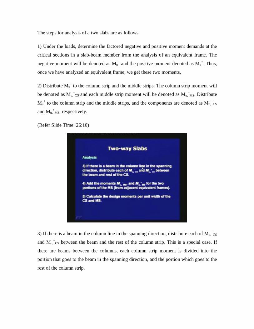
(Refer Slide Time: 26:10)
3) If there is a beam in the column line in the spanning direction, distribute each of Mu,‒
CS
and Mu,+
CS between the beam and the rest of the column strip. This is a special case. If
there are beams between the columns, each column strip moment is divided into the
portion that goes to the beam in the spanning direction, and the portion which goes to the
rest of the column strip.

4) Add the moments Mu,‒
MS and Mu,+
MS for the two portions of the middle strip which are
from adjacent equivalent frames. We have now calculated the middle strip moments for
one equivalent frame.
5) Calculate the design moments per unit width of the column strip and middle strip.
Thus, once we get the total moments acting in a column-strip and the middle-strip, and
given their widths, we can find out the moment per unit width for the column strip and
the middle strip. Based on the moment per unit width, we can design the reinforcement.
(Refer Slide Time: 27:49)
Once the design moments per unit width of the column strip and middle strip are known,
the steps of design for prestressing steel are same as that for one-way slab. The profile of
the tendons is selected similar to that for continuous beams.
The flexural capacity of prestressed slab is controlled by total amount of prestressing
steel and prestress rather than by tendon distribution. Still some guidelines are given on
the tendon distribution. It has been found that the flexural capacity of a slab is
independent of the distribution of the tendons. Hence, there is flexibility in placing the
tendons.

(Refer Slide Time: 29:23)
The maximum spacing of tendons or groups of tendons should be limited to 8h or 1.5 m,
whichever is less. Here, h is the thickness of the slab. A minimum of 2 tendons shall be
provided in each direction, through the critical section for punching shear around a
column. The critical section shall be described in the next module.
We had seen earlier that around a column, the slab needs higher reinforcement. It is
recommended that at least two tendons should pass through the critical section around the
slab-to-column junction. Grouping of tendons is permitted in band beams; that is the
purpose of having a wide beam is to accommodate the tendons in its width.

(Refer Slide Time: 30:47)
A minimum amount of non-prestressed reinforcement is provided in each direction based
on temperature and shrinkage requirement. As per IS:456-2000, Clause 26.5.2.1, the
minimum amount of reinforcement (denoted as Ast,min and in mm2) for unit width of slab
is given as follows.
Ast,min = 0.15% 1000h, for Fe 250 grade of steel
Ast,min = 0.12% 1000h, for Fe 415 grade of steel.
Here, we are considering a unit width of the slab in each direction, and hence the breadth
is equal to 1000 mm. The reinforcement is based on the cross-section of unit width of
slab.
Next, we are describing features in modelling and analysis of an equivalent frame.

(Refer Slide Time: 32:02)
1) Gross section versus cracked section.
The difficulty in analyzing a reinforced concrete structure is that the members may crack
under service loads. The chances of cracking of the slabs are reduced when they are
prestressed. For determining the stiffness of the members, gross section can be
considered in place of cracked section.
When we are developing a computational model, we have to assign the stiffness of the
slab-beam members and the column members. We can assign them based on gross
sections. If we are consistent throughout the building, then the forces will not be much
different from those based on cracked section stiffness. Since the gross section properties
are easier to calculate, the code allows us to use them.

(Refer Slide Time: 33:26)
2) Equivalent column.
The actual column needs to be replaced by an equivalent column to consider the
flexibility of the transverse beam in the rotation of the slab. The portions of the slab in the
middle strip rotate more than the portions in the column strip because of the torsional
deformation of the transverse beam.

(Refer Slide Time: 33:55)
Let us understand this by a sketch of a slab-to-column junction. The slab is split to show
the behaviour across the width of the equivalent frame. The arrows represent the rotation
in the slab. For portions closer to the column, the rotation is less. As we move out from
the column, the rotation increases. Thus, the flexibility in the slab is more away from the
columns than closer to them.
(Refer Slide Time: 35:07)

To account for this increased flexibility, an equivalent column is defined in place of the
actual column. The transverse beam need not be a visible beam, but a part of the slab in
the transverse direction bounded by the edges of the column or column capital. In
presence of beam or drop panel or column capital, the cross-section of the modelled
transverse beam is taken as follows.
(Refer Slide Time: 35:10)
In this sketch, we are seeing the cross-section of the transverse beam that is considered.
As I said, the transverse beam need not be a visible beam. It can be a part of the slab
which is bound by the column. In the figure on the right side there is no visible beam, but
the modelled transverse beam is the part of the slab which is bound between the column
faces. In the middle figure, there is a column capital and a drop panel and we see that the
part of the drop panel which is bound within the column capital is selected as the
transverse beam. In the left figure, there is a visible transverse beam. In presence of the
transverse beam, we consider a part of the slab to be a part of the transverse beam. This
part of the slab is determined by a 45 projection of the part of the transverse beam
extending below the slab. Thus, once we are able to identify the transverse beam, we can
find out the properties of the equivalent column.

(Refer Slide Time: 36:43)
The flexibility of the equivalent column is equal to the sum of the flexibilities of the
actual column and the transverse beam. This is the basic idea of defining the equivalent
column.
1/Kec = 1/Kc + 1/Kt
Here, we are adding the flexibilities to consider the increased rotation of the slab as we
move away from the column. Kec is equal to the flexural stiffness of the equivalent
column. Kc = Kc,upper + Kc,lower, where Kc,upper is the flexural stiffness of the upper
column, Kc,lower is the flexural stiffness of the lower column, and Kt is the torsional
stiffness of the transverse beam. Thus, this expression is the adding up of flexibilities,
where a flexibility is the inverse of stiffness. When we add the flexibilities, we get the
flexibility of the equivalent column from which we calculate the stiffness of the
equivalent column.

(Refer Slide Time: 38:26)
An approximate expression for the flexural stiffness of a column (Kc) is given as follows.
Kc = 4EcIc/(L ‒ 2h)
This is very close to the expression that we learn from the slope deflection method in
basic structure analysis. Ec is the modulus of the concrete, L is the length of the column,
h is the thickness of the slab and Ic is the moment of the inertia of the column. Thus, this
expression of flexural stiffness can be applied to the upper and lower columns at a joint.

(Refer Slide Time: 39:08)
An approximate expression for the torsional stiffness of the transverse beam (Kt) is given
below.
Kt = 9EcC/I2 (1 ‒ c2/l2)
Here, C is the equivalent polar moment of inertia of transverse beam, c2 is the dimension
of the column in the transverse direction, l2 is the width of the equivalent frame.
(Refer Slide Time: 39:52)

For a rectangular section, the expression of C is given below. Note that C is analogous to
the polar moment of inertia for a circular section. For a rectangular section, it is difficult
to define C exactly and an approximate expression is given as follows.
C = (1 ‒ 0.63 x/y) x3y/3
The summation is taken over the component rectangles of a compound section which we
shall come to later. Let us first understand what is x and y for a rectangular section. Here,
x and y are the smaller and larger dimensions of the transverse beam. The expression of
C is a lower bound estimate, that is, the calculated value is always lower than the actual
moment of inertia of the transverse beam.
(Refer Slide Time: 41:28)
When we have a compound section, we make a summation over the individual rectangles
to find out the value of C. The splitting of the compound section into component
rectangles should be such so as to maximize the value of C. For the following two cases
of splitting, select the larger value of C.
Since C is a lower bound value, the actual value will be higher than the value calculated
based on the individual rectangles. Hence, we can divide a compound section in such a
way that we can get the maximum value of C, which anyhow will be lower than the true

value. Thus, if we have an inverted L-shaped transverse beam, then we can either split it
into two rectangles as shown on the left or we can split into two rectangles which is on
the right. Now for each rectangle, we have to identify x and y which are the smaller and
larger dimensions, respectively. Place those values in the expression, take the summation
and calculate the value of C. Once we have got the value of C for both the schemes of
splitting, we pick up the value which is higher. Thus, once we calculate C and the other
geometric properties, we can find out the torsional stiffness of the transverse beam, which
is denoted as Kt.
(Refer Slide Time: 43:15)
If there is a beam in the column strip in the spanning direction, then Kt is replaced by
Kt(Isb/Is). Here, Is is the moment of inertia of slab without the projecting portion of the
beam as shown in the shaded area in Figure a. Isb is the moment of inertia of slab
considering it as a T-section, as shown in the shaded area in Figure b. Thus, if there are
beams in between the column lines, in that case Kt is increased.

(Refer Slide Time: 44:33)
3) Slab-beam members.
The variation of the flexural moment of inertia of a slab-beam member is considered as
follows. The value of the moment of inertia is constant (say equal to I1) in the prismatic
portion; that is, in between the faces of the columns or column capitals or drop panels. It
is also constant, with a different value (say equal to I2) in the region of a drop panel.
(Refer Slide Time: 45:22)

Since the moment of inertia varies in the region from the face of the column or column
capital to the center line of the column, it is approximated to a constant value equal to the
following.
I2/(1 ‒ (c2/ l2)2
Here, I2 is the value at the face of the column or column capital.
(Refer Slide Time: 45:55)
Let us understand the recommendation by the help of a sketch. The top figure is the
elevation of an equivalent frame at a particular floor level within a bay. The flexural
moment of inertia is varying along the span of the slab-beam member. In the middle
region, it is constant equal to a value of I1; at the drop panels it has a value of I2 and from
the face of the column capital to the center line of the column it varies. The code says that
in this region from the face of the column capital to the center of the column, we can
consider a constant flexural moment of inertia. Thus, for this particular case, we have 3
values of the moment of inertia for the slab-beam member: I1, I2 and finally, a value
which is from the face of the column capital to the center line of the column.

(Refer Slide Time: 47:19)
4) Arrangement of live load.
Since the factored live load (wu,LL) may not occur uniformly in all the spans in a floor, a
distribution is considered to generate the maximum values of the negative and positive
moments at the critical section.
When we are applying the gravity load, we have to be careful that if the live load should
be placed uniformly or not. The dead load can be placed as is given for the member
section, but the live load may not be uniform throughout a span and for the different
spans in the equivalent frame.

(Refer Slide Time: 48:05)
The coded recommendation is, if the distribution of wu,LL is known, then the load is
applied accordingly. If the distribution is not known, then a pattern loading is considered
based on the value of wu,LL with respect to that of the factored dead load wu,DL. Of course,
the load case with wu,LL on all the spans should be also analyzed. Let us understand this
with the help of a sketch.
(Refer Slide Time: 48:37)

a) For the live load to be less than three quarters of the dead load (wu,LL ≤ ¾ wu,DL), which
is the case for most of the buildings, the possible variation in wu,LL in the different spans
is neglected. Thus, the live load can be applied uniformly. In this sketch, you see that the
live load has been applied uniformly in all the spans, and we are analyzing the member
with that loading scheme.
(Refer Slide Time: 49:18)
b) If the live load exceeds three quarters of the dead load (wu,LL > ¾ wu,DL), that means
the live load is substantially high, then for maximum moment of Mu+ in a span, ¾ wu,LL is
applied on the span and alternate spans. For example, if the maximum value of Mu+ in
span BC of the frame is to be determined, then ¾ wu,LL is placed in spans BC and DE.
That means, if we are looking for the mid-span moment of BC, we shall place the live
load in BC and alternate span like DE. The value of the live load is three fourth of the
live load coming in the tributary width, which is ¾ wu,LL l2.
For maximum value of Mu‒ near a support, ¾ wu,LL is applied on the adjacent spans of the
support only. For example, if the maximum value of Mu‒ near support B is to be
determined, then ¾ wu,LL l2 is placed in spans AB and BC.
We also have to analyze the case where the live load is uniformly placed in all the spans.
Thus, from these load conditions we find out the maximum values of the positive

moments in the spans and the negative moments near the supports. These maximum
values are called envelope values from which we design the slab.
(Refer Slide Time: 51:30)
5) Critical section near a support.
The critical section is determined as follows.
a) At an interior support, it is the face of support (which is the column or column capital
if any), but not further than 0.175l1 from the center line of the column.
b) For an exterior support, it is at a distance from the face of column not greater than half
the projection of the column capital (if any).

(Refer Slide Time: 52:34)
Next, we understand the distribution of moments in the two strips, column strip and
middle strips. In absence of rigorous analysis, say finite element analysis, the procedure
for reinforced concrete slabs may be used to distribute the moments Mu+ and Mu
‒ to the
column strip and middle strip. ACI 318-02 does not recommend the procedure to be used
for prestressed slabs.
Thus, we can use this procedure of distributing the moments with caution. It is preferred
that we do a more rigorous analysis to find out the moments in the column strip and the
middle strips.

(Refer Slide Time: 52:55)
1) The distribution of Mu‒ at an interior support is as follows. The column strip gets 75%
and the middle strips get 25% of the negative moment.
Mu,‒
CS = 0.75 Mu‒
Mu,‒
MS = 0.25 Mu‒
Here, Mu,‒
CS is the negative moment in the column strip. Mu,‒
MS is the total negative
moment in the two middle strips at the two sides.

(Refer Slide Time: 53:54)
2) The distribution of Mu‒ at an exterior support is as follows.
If the width of the column or wall support is less than ¾l2, the column strip gets the full
negative moment.
Mu,‒
CS = Mu‒
Mu,‒
MS = 0.
If the width of the column or wall support is greater than ¾l2, then Mu‒ is uniformly
distributed along the width l2. Thus, depending on the width of the column with respect to
the width of the equivalent frame, we decide upon whether the full negative moment
should come to the exterior column or not.

(Refer Slide Time: 54:08)
3) Distribution of Mu+ at mid-span. The column strip gets 60% and the middle strip gets
40% of the positive moment.
Mu,+
CS = 0.60 Mu+
Mu,+
MS = 0.40 Mu+
Again, note that for the middle strips, Mu,+
MS represents the total positive moment in the
two middle strip at the two sides.

(Refer Slide Time: 54:33)
The total moments in middle strip (which are Mu,‒
MS and Mu,+
MS) are distributed to the
parts of the two middle strips at the two sides of the equivalent frame, proportional to
their widths. The combined middle strips from two adjacent equivalent frames, is
designed for the sum of the moments assigned to its parts.
That means, for a particular equivalent frame the value that we get for the middle strip,
we distribute that in the two portions of the middle strips at the two sides. Once we have
distributed for each middle strip, we combine the two values from one equivalent frame
and the adjacent equivalent frame, to get the total moment in that particular middle strip.

(Refer Slide Time: 55:21)
Thus, in today’s lecture, we have introduced the two-way slabs. We said that a non-
rectangular slab is always designed as a two-way slab. A rectangular slab, if it is
supported on all the four sides then it is designed as a two-way slab depending on the
length-to-breadth ratio. If the length-to-breadth ratio is less than 2, then we design a
rectangular slab as a two-way slab which spans in both the directions.
There can be different types of two-way slabs. The first is the flat plate, which does not
have any beams or drop panels or column capitals. The second type is the flat slabs which
do not have any beam, but it can have drop panel or column capital. The third type is the
two-way slab with beams, where beams are running in between the column lines. The flat
plates or flat slabs can have beams at the edges, which are called spandrel beams.
The design of two-way slabs can be done by two methods. For flat slabs and flat plates,
the method is given in Section 31 of IS: 456-2000. This method is also applicable for two
way slabs with beams that can deflect. There is a second method for the two-way slabs
whose beams are stiff enough and their deflection can be neglected. The second method
is given in Annex D of IS: 456-2000.

In this module, we discussed the method in Section 31 of IS: 456 which is used for flat
plates and flat slabs. Now, again in that section there are two methods given. One is the
simplified method which is called the direct design method. This is not suitable for
prestressed slabs. The second method, which is the equivalent frame method and is based
on computer analysis, is recommended for two-way prestressed slabs.
In the equivalent frame method, first we define the equivalent frames in each orthogonal
direction. An equivalent frame is a slice of a building along a column line whose width
spans between the central lines of the two adjacent bases. Within an equivalent frame, we
define a column strip and two middle strips at the sides. Once an equivalent frame is
defined, we analyze the frame for gravity loads and lateral loads if any, and find out the
moments in the critical sections, the positive moments in the spans and the negative
moments near the supports.
Once these critical moments are known, we distribute each moment along the width of
the equivalent frame, from which we calculate the moment per unit width of the slab.
Once we know this value, we can design the prestressing tendon just the way we have
done for one-way slab. In our next lecture, we shall move on to the design for shear of
two-way slabs.
Thank you.