Embed Size (px)
Citation preview

CAMCORP, Inc.Phone: 913-831-0740 ~ Fax: 913-831-9271
www.camcorpinc.com
PRESSURE / VACUUM BLOWER PACKAGE
INSTRUCTION, OPERATIONS & MAINTENANCE MANUAL
CAMCORP, Inc.Phone: 913-831-0740 ~ Fax: 913-831-9271
www.camcorpinc.com
TABLE OF CONTENTS
General Information -------------------------------------------------2
Principle of Operation -----------------------------------------------3
Installation ------------------------------------------------------------4
Start-Up------------------------------------------------------------- 5-6
Maintenance ----------------------------------------------------------7
Troubleshooting ------------------------------------------------------8
NOTE:
It is the owner’s responsibility to maintain the safety features included with this equipment. The safety features may include, but not necessarily be limited to: guards, access doors and covers, explosion vents, warning decals, caution decals, and advisory decals. Replacement features are available from CAMCORP.
1

2
CAMCORP, Inc.
Phone: 913-831-0740 ~ Fax: 913-831-9271
www.camcorpinc.com
GENERAL COMMENTS:
CAMCORP supplies air pump packages comprised of positive displacement blowers manufactured by various companies. A Service Manual for your specific blower is included as an inset in this manual. For specific maintenance and lubrication information, please refer to this insert.
-READ & UNDERSTAND SAFETY DECALS-
Installation and Operation Cautions:
Be sure that the motor is wired for correct rotation; some models of blower are unidirectional and damage could occur if rotation is reversed. Refer to certified drawing or consult CAMCORP representative for rotation.
Blowers are shipped without lubrication oil, do not operate before lubrication.
All system piping must be clean internally before connecting to blower.
Check lubrication level only when blower is stopped.
Keep inlet and inline filters clean.
Keep belts properly tensioned and aligned.
Use of a check valve on pressure and combination packages will prevent reversing of blower on shutdown.
Keep pressure and/or vacuum relief valves in good condition so that maximum pressure or vacuum is not exceeded.
Never attempt to regulate airflow by restricting intake or exhaust of a positive displacement blower.

3
CAMCORP, Inc.
Phone: 913-831-0740 ~ Fax: 913-831-9271
www.camcorpinc.com
PRINCIPLE OF OPERATION
CAMCORP blower packages are set up to provide air to a pressure conveying system or vacuum required for a negative pressure system. Typically the positive displacement blower used on such a package is not capable of supplying air to a pressure higher then 15 psig or vacuum greater then 14” Hg. Depending on the specific blower, it may have a maximum pressure or vacuum capability of somewhat less than that. Because of limitations involved, the blower, motor and line size of the system must be designed specifically to meet the requirements of the system.
Because of the tight clearances used in the design and manufacture of the PD blowers, they require filtered intake air. Proper maintenance of the intake filter will help insure a long service life for your blower.
We recommend you give consideration to building certain precautions into your system. Due to unforeseen circumstances your system may at some point experience an upset condition. By allowing for this when setting up your system, you may minimize the affect of such an occurrence. Three major areas should be considered: the positive displacement blower, the motor and the integrity of the system controls.
Provided, as standard equipment on all of our blower packages is a mechanical relief valve, which is factory set at or below the pressure or vacuum limit of the specific blower. This protects the blower from overheating because flow is decreasing if a line plugs or valve closes at the wrong time. This type of blower is not designed to run at zero airflow.
A properly sized and installed motor starter provides protection for your motor. Hire a qualified electrician to design and install the electrical service to your system.
The integrity of the controls for your system can usually best be maintained during an upset condition by proper use of a pressure or vacuum switch. A pressure/vacuum switch set two to three PSI/Hg. above the expected operating pressure of your system will allow a high pressure or vacuum signal to initiate a preventative action. Check with CAMCORP for expected operating pressure. This may involve stopping the infeed or material to the system to allow it a certain time to clear itself or it may be as simple as triggering an alarm to alert an operation to the condition.
Caution must be taken to be sure that any steps initiated by such an upset condition does not create a problem or even a hazard elsewhere in your process. For example, your upstream equipment may need to be shut down in a very specific sequence. In any case, you need to analyze the affect on your complete process before establishing the actions initiated by an upset condition.

4
CAMCORP, Inc.
Phone: 913-831-0740 ~ Fax: 913-831-9271
www.camcorpinc.com
INSTALLATION
CAMCORP’s positive displacement blower package consists of a positive displacement blower, a vertical or horizontal frame assembly, a motor, take-up table, or motor slide rails, V-belt drive and belt guard, an air intake or inline filter, intake and discharge silencer, a pressure or vacuum relief valve preset at the maximum pressure or vacuum rating of the blower, flexible connections, a check valve (pressure blower assemblies only), pressure/vacuum gauge and pressure or vacuum switch. (Vacuum blower package does not include an inlet silencer as a standard offering)
Assembly may be accomplished through the following:
1. Locate and anchor the blower base assembly in its permanent location.
2. Check all bolted connections for tightness.
3. Check belts for proper tightness.
4. Zero out pressure or vacuum gauge.
5. Set pressure on pressure/vacuum switch to correct setting.
Lubrication:
CAMCORP uses positive displacement blowers from several manufacturers. General lubrication information is given in the Maintenance Section; for specific information on your positive displacement blower, see the manufacturers manual included with this manual.
CAUTION: All blowers are shipped dry from the factory. Do not attempt to run the blower before following proper lubrication instructions as permanent damage to the gears, bearings and seals will occur.
CAMCORP, Inc. Phone: 913-831-0740 ~ Fax: 913-831-9271
www.camcorpinc.com
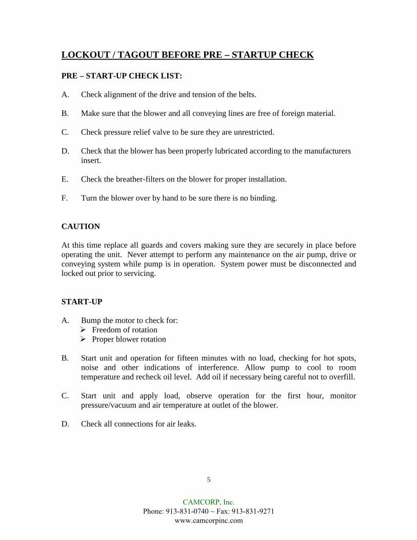
LOCKOUT / TAGOUT BEFORE PRE – STARTUP CHECK
PRE – START-UP CHECK LIST:
A. Check alignment of the drive and tension of the belts.
B. Make sure that the blower and all conveying lines are free of foreign material.
C. Check pressure relief valve to be sure they are unrestricted.
D. Check that the blower has been properly lubricated according to the manufacturers insert.
E. Check the breather-filters on the blower for proper installation.
F. Turn the blower over by hand to be sure there is no binding.
CAUTION
At this time replace all guards and covers making sure they are securely in place before operating the unit. Never attempt to perform any maintenance on the air pump, drive or conveying system while pump is in operation. System power must be disconnected and locked out prior to servicing.
START-UP
A. Bump the motor to check for: ! Freedom of rotation ! Proper blower rotation
B. Start unit and operation for fifteen minutes with no load, checking for hot spots, noise and other indications of interference. Allow pump to cool to room temperature and recheck oil level. Add oil if necessary being careful not to overfill.
C. Start unit and apply load, observe operation for the first hour, monitor pressure/vacuum and air temperature at outlet of the blower.
D. Check all connections for air leaks.
5

6
CAMCORP, Inc.
Phone: 913-831-0740 ~ Fax: 913-831-9271
www.camcorpinc.com
E. Check the amp draw of the motor to be sure that the full load amp rating is not exceeded. See motor nameplate.
! Do not operate blower beyond manufacturers recommended limits.
! Be aware that there are also minimum recommended RPM limitations below which adequate lubrication will not be maintained.
! Consult the manufacturers insert or factory for the specific limits for this blower.

7
CAMCORP, Inc.
Phone: 913-831-0740 ~ Fax: 913-831-9271
www.camcorpinc.com
MAINTENANCE
A. Check oil level daily
B. Refer to the general lubrication guidelines in this manual for recommended frequency of oil change and type of oil. For more specific information on blower maintenance and lubrication see the manufacturer’s insert (manual) accompanying this manual.
C. Clean the intake or inline filter every 40 hours or more often if dust conditions are severe. The filter element is washable using luke warm water with mild detergent.
D. Check the drive belts for tension after the first 24 hours of operations and every 100 hours thereafter. Sheaves and belts should be inspected every 200 hours.
E. Silencers should be inspected periodically for: 1) being plugged, 2) corrosion, 3) oil coating (discharge silencers) and for any deterioration.

CAMCORP, Inc. Phone: 913-831-0740 ~ Fax: 913-831-9271
www.camcorpinc.com
TROUBLESHOOTING POSITIVE DISPLACEMENT ROTARY BLOWERS
Symptom
Noisiness
Possible Causes
Rotor-to Rotor Contact
Failing Bearing (s)
Failing Gears
Failing Lubricated Coupling or Joint
Loose Attached Hardware
Air Leakage
8
Possible Sources
Rust Build up or Rotors Rotors Our of Time Excessive Pressure Ratio Failed Bearings (s) Failed Gears
Faulty Installation Non-spec Oil Contaminated Oil Insufficient Oil Improperly Mounted Sheave Over-tightened Belts
Insufficient Backlash Non-spec Oil Contaminated Oil Insufficient Oil Sever Torsional Vibration
Non-spec Grease Contaminated Grease Insufficient Grease
Belt Guard Pump Mounting Bracket Frame Members In/Out Piping Supports
Improper Relief Valve Setting Blown Gaskets Loose Piping Joints

CAMCORP, Inc. Phone: 913-831-0740 ~ Fax: 913-831-9271
www.camcorpinc.com
Symptom
Poor Performance
Possible Causes
Belt Flutter
Restricted Inlet
Down Stream Restriction
Erroneous Pressure or Vacuum Indication
Air Leakage
Insufficient Rotor Speed
Excessive Rotor Clearances
Change in Conveyed Material
9
Possible Sources
Insufficient Static Tension Sheave Misalignment Sever Torsional Vibration
Clogged Filter Element Collapsed Inlet Hose
Clogged Dust Filter Undersized Dust Filter Faulty Check Plate Improperly Installed Check Plate
Loose Gauge Connection Gauge Movement Damaged Gauge Inaccurately Calibrated
Improper Relief Valve Setting Blown Gaskets Loose Piping Joints
Wrong Sheave Set Wrong Motor Speed Slipping Belts
Abrasive Wear of Rotor Surfaces Rotor “Lag” Timed
Material More Difficult to Fluidize Material of Higher Density Moisture Content of Material Too High

CAMCORP, Inc. Phone: 913-831-0740 ~ Fax: 913-831-9271
www.camcorpinc.com
Symptom
Leaking Oil
Chronic Fuse Blowing or Circuit Breaking
Overheating
Possible Causes
Failed Oil Seals
End Cover Seams Not Tight
Oil Foaming
Excessive Motor Amperage
Underrated Fuses
Premature Heater Strip Actuation
Excessive Pressure Ratio
Insufficient Rotor Speed
10
Possible Sources
Foreign Material in Seal Bores Faulty Installation Non-spec Oil Contaminated Oil Overheated Rotor Shafts
Bolts Loose Gaskets Torn
Non-spec Oil Oil Cavities Overfilled
Excessive Pressure Ratio Excessive Pump Speed Line Voltage Drop Air Density Increase Loose Electrical Connections Foreign Material in Air Box
Unusually High Ambient Temperature Underrated Heater Strips
Clogged Filter Element Collapsed Inlet Hose Clogged Dust Vent Filter Undersized Dust Vent Filter Clogged Diffusion Pads Faulty Check Plate Improperly Installed Check Plate
Wrong Sheave Set Wrong Motor Speed Slipping Belts

CAMCORP, Inc. Phone: 913-831-0740 ~ Fax: 913-831-9271
www.camcorpinc.com
Pressure and vacuum switches contain one or two single pole, double throw switches rated (continuous inductive) for 10 amps at 125 or 250 volts or 3 amps at 480 volts.
The installation and use of this electrical apparatus must be in accordance with the national electrical code and any other applicable local codes and ordinances.
Standard motors supplied by CAMCORP will be 230/460 volt, 3 phase, 60 cycle and control circuits will be 110 volt, single phase, 60 cycle.
Pressure or Vacuum Switch Adjustments: Turn adjustment screw clockwise to lower actuation point.
11

M-D Pneumatics™
Rotary Positive Displacement Air Blower
EQUALIZER DF™ 4504 4506 4509 4512
4604 4606 4609 4612
6012 6016 6024
EQUALIZER RM™
Models
03/2004
LEADING THE SEARCH FOR INNOVATIVE SOLUTIONS
4840 West Kearney Street Springfield, Missouri USA 65803-8702 Tel 417 865-8715 800 825-6937 Fax 417 865-2950 E-mail: [email protected]
http://pneumatics.tuthill.com
INSTALLATION OPERATION MAINTENANCE REPAIR
MANUAL WARNING
DO NOT OPERATE BEFORE READING MANUAL.
Model 4500 Equalizer DF
Model 4600 Equalizer RM
Model 6000 Equalizer RM

SAFETY INSTRUCTIONS
1. Do not operate before readingthe enclosed instructionmanual.
2. Use adequate protection,warning and safety equipmentnecessary to protect againsthazards involved in installation
Do not operate without guards in place
Do not touch hot surfaces
SAFETY WARNING • Keep hands and clothing away from rotating machinery, inlet and discharge openings.• Blower and drive mounting bolts must be secured.• Drive belts and coupling guards must be in place.• Noise level may require ear protection.• Blower heat can cause burns if touched.
TUTHILL VACUUM & BLOWER SYSTEMS Springfield, MO USA
NOTICE
The above safety instruction tags were attached to your unit prior to shipment. Do not remove, paint over or obscure in any manner.
Failure to heed these warnings could result in serious bodily injury to the personnel operating and maintaining this equipment.
Keep body and clothing away from machine openings
Hearing Protection Required
! WARNING ! WARNING ! WARNING
! CAUTION
2

TABLE OF CONTENTS
SAFETY INSTRUCTIONS & WARNING TAGS 2
SAFETY PRECAUTIONS 3
INTRODUCTION 4
OPERATING DATA 4
INSTALLATION 5
LUBRICATION & OIL RESERVOIR CAPACITIES 6
FLOW CONFIGURATION 6
TROUBLESHOOTING 8
RECOMMENDED SHUTDOWN PROCEDURE / FLOW DIRECTION BY ROTATION 9
DISASSEMBLY & INSPECTION 10
ASSEMBLY 11
SPECIAL TOOL DRAWINGS - MODELS 4500 / 4600 13
SPECIAL TOOL DRAWINGS - MODEL 6000 14
MAINTENANCE & SERVICE SPECIFICATIONS SHEET 15
MAXIMUM OPERATING LIMITS 15
CUTAWAY VIEW AND PARTS LIST - MODELS 4504, 4506, 4509, 4512 16-17
CUTAWAY VIEW AND PARTS LIST - MODELS 4604, 4606, 4609, 4612 18-19
CUTAWAY VIEW AND PARTS LIST - MODELS 6012, 6016, 6024 20-21
WARRANTY STATEMENT 22
SECTION PAGE
PREVENTATIVE MAINTENANCE / STARTUP CHECKLIST 7
SAFETY PRECAUTIONSFor equipment covered specifically or indirectly in this instruction book, it is important that all personnel observe safety
precautions to minimize the chances of injury. Among many considerations, the following should particularly be noted:
• Blower casing and associated piping or accessories may become hot enough to cause major skin burns on contact.• Internal and external rotating parts of the blower and driving equipment can produce serious physical injuries. Do not
reach into any opening in the blower while it is operating, or while subject to accidental starting. Cover external movingparts with adequate guards.
• Disconnect power before doing any work, and avoid bypassing or rendering inoperative any safety or protectivedevices.
• If blower is operated with piping disconnected, place a strong, coarse screen over the inlet and avoid standing indischarge air stream.
• Avoid extended exposure in close proximity to machinery with high intensity noise levels.• Use proper care and good procedures in handling, lifting, installing, operating, and maintaining the equipment.• Other potential hazards to safety may also be associated with operation of this equipment. All personnel working in or
passing through the area should be warned by signs and trained to exercise adequate general safety precautions.• Hearing protection may be required depending on silencing capabilities.
IMPORTANT
In order to assure you of the full benefits of our product warranty, please complete, tear out and return the warranty registration card located on the back cover of this manual, or you can visit our product registration web page at http://pneumatics.tuthill.com/product_registration
3

INTRODUCTION
CONGRATULATIONS on your purchase of a new EQUALIZER® Rotary Positive Displacement Air Blower from Tuthill
Vacuum & Blower Systems. Please examine the blower for shipping damage, and if any damage is found, report it immediately to the carrier. If the blower is to be installed at a later date make sure it is stored in a clean, dry location and rotated regularly. Make sure covers are kept on all openings. If blower is stored outdoors be sure to protect it from weather and corrosion.
EQUALIZER blowers are built to exacting standards and if properly installed and maintained will provide many years of reliable service. We urge you to take time to read and follow every step of these instructions when installing and maintaining your blower. We have tried to make these instructions as straightforward as possible. We realize getting any new piece of equipment up and running in as little time as possible is imperative to production.
WARNING: Serious injury can result from operating or repairing this machine without first reading the service manual and taking adequate safety precautions.
IMPORTANT: Record the blower model and serial numbers of your machine in the OPERATING DATA form below. You will save time and expense by including this reference identification on any replacement part orders, or if you require service or application assistance.
OPERATING DATA It will be to the user’s advantage to have the requested data filled in and available in the event a problem should develop in the blower or the system. This information is also helpful when ordering spare parts.
Model No. __________________________________ V-Belt Size ______________ Length _____________
Serial No. __________________________________ Type of Lubrication: (Recorded from nameplate on unit) _____________________________
Startup Date ________________________________ ________________________
Blower RPM ________________________________ Pressure ___________________________________
Blower Sheave Diameter ______________________ Vacuum ___________________________________
Motor Sheave Diameter _______________________ Any other special accessories with this unit
Motor RPM _______________ HP ______________ ___________________________________________
NOTES:
4

INSTALLATION
WARNING: Customers are cautioned to provide adequate protection, warning and safety equipment necessary to protect personnel against hazards involved in the installation and operation of this equipment in the system or facility. Do not use air blowers on explosive or hazardous gases. Each size blower has limits on pressure differential, running speed, and discharge temperature, which must not be exceeded. These limits are shown on the table "Maximum Operating Limits” on page 15.
LOCATION Install the blower in a clean, dry, and well lighted area if possible. Leave plenty of room around the blower for inspection and maintenance.
FOUNDATION We recommend a solid foundation be provided for permanent installation. It is necessary that a suitable base be used, such as a steel combination base under blower and motor, or a separate sole plate under each. Before tightening the bolts, check to see that both mounting feet are resting evenly on the foundation, shim as necessary to eliminate stress on the base when the bolts are tightened. Where a solid foundation is not feasible, care must be taken to insure that equipment is firmly anchored to adequate structural members.
DRIVE When the blower is V-belt driven the sheaves must be positioned so that the hub face of the blower sheave is not more than 1/4" (6.5 mm) from the blower drive end plate and the driver sheave is as close to the driver bearing as possible. Care should be taken when installing sheave onto shaft. The faces of the sheaves should be accurately in line to minimize belt wear. Adjust the belt tension to the belt manufacturer’s specifications. For installations where the blower is to be operated by direct drive, selection of the driver should be such as not to exceed the maximum speed ratings of the blower. (See table "Maximum Operating Limits” on page 15.) A flexible type coupling should be used to connect driver and blower shafts. The two shafts must be aligned within .005" (.13 mm) T.I.R. (Total Indicated Runout) .002 (.07mm) T I R face run out on coupling.
PROTECTIVE MATERIALS Remove protective materials from the shaft. Remove the protective covers from the inlet and outlet ports and inspect the interior for dirt and foreign material.
WARNING: Keep hands, feet, foreign objects and loose clothes from inlet and outlet openings to avoid injury or damage if lobes are to be rotated at this point.
LUBRICATION Do not start up the blower until you are positive that it has been properly and fully lubricated. (See Lubrication Section on page 6.)
PIPING Inlet and outlet connections on all blowers are large enough to handle maximum volume with minimum friction loss. Maintain same diameter piping. Silencers must not be supported by the blower. Stress loads and bending moments must be avoided. Be certain all piping is clean internally before connecting to the blower. We recommend placing a 16-mesh wire screen backed with hardware cloth at or near the inlet connections for the first 50 hours of use until the system is clean. Make provisions to clean the screen after a few hours of operation and completely discard it once the system is clean, as it will eventually deteriorate and small pieces going into the blower can cause serious damage. A horizontal or vertical air flow piping configuration is easily achieved by rearranging the mounting feet position.
WARNING: Do not operate equipment without adequate silencing devices since high noise level may cause hearing damage. (Reference OSHA Standards.)
RELIEF VALVES We recommend the use of relief valves to protect against excessive pressure or vacuum conditions. These valves should be tested at initial start-up to be sure they are properly adjusted to relieve at or below the maximum pressure differential rating of the blower.
CAUTION: Upon completion of the installation, and before applying power, rotate the drive shaft by hand. It must move freely. If it does not, look for uneven mounting, piping strain, excessive belt tension or coupling misalignment or any other cause for binding. If blower is removed and still does not rotate freely, check inside the blower housing for foreign material.
5
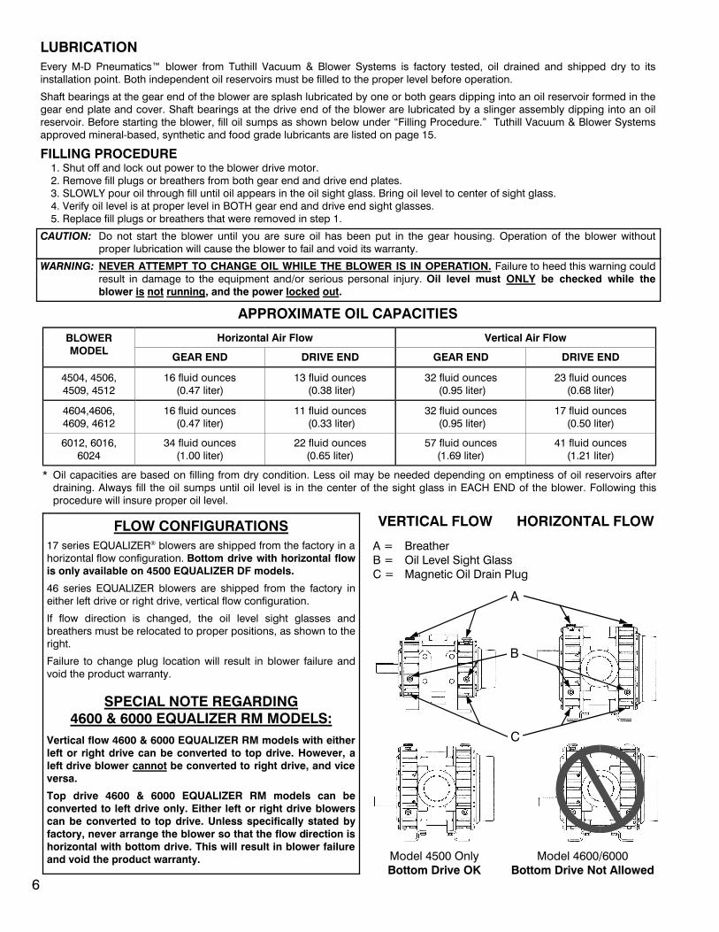
LUBRICATION
Every M-D Pneumatics™ blower from Tuthill Vacuum & Blower Systems is factory tested, oil drained and shipped dry to its installation point. Both independent oil reservoirs must be filled to the proper level before operation.
Shaft bearings at the gear end of the blower are splash lubricated by one or both gears dipping into an oil reservoir formed in the gear end plate and cover. Shaft bearings at the drive end of the blower are lubricated by a slinger assembly dipping into an oil reservoir. Before starting the blower, fill oil sumps as shown below under “Filling Procedure.” Tuthill Vacuum & Blower Systems approved mineral-based, synthetic and food grade lubricants are listed on page 15.
FILLING PROCEDURE 1. Shut off and lock out power to the blower drive motor.2. Remove fill plugs or breathers from both gear end and drive end plates.3. SLOWLY pour oil through fill until oil appears in the oil sight glass. Bring oil level to center of sight glass.4. Verify oil level is at proper level in BOTH gear end and drive end sight glasses.5. Replace fill plugs or breathers that were removed in step 1.
CAUTION: Do not start the blower until you are sure oil has been put in the gear housing. Operation of the blower without proper lubrication will cause the blower to fail and void its warranty.
WARNING: NEVER ATTEMPT TO CHANGE OIL WHILE THE BLOWER IS IN OPERATION. Failure to heed this warning could result in damage to the equipment and/or serious personal injury. Oil level must ONLY be checked while the blower is not running, and the power locked out.
APPROXIMATE OIL CAPACITIES
Horizontal Air Flow Vertical Air Flow
GEAR END DRIVE END GEAR END DRIVE END
4604,4606, 4609, 4612
16 fluid ounces (0.47 liter)
11 fluid ounces (0.33 liter)
32 fluid ounces (0.95 liter)
17 fluid ounces (0.50 liter)
6012, 6016, 6024
34 fluid ounces (1.00 liter)
22 fluid ounces (0.65 liter)
57 fluid ounces (1.69 liter)
41 fluid ounces (1.21 liter)
BLOWER MODEL
4504, 4506, 4509, 4512
16 fluid ounces (0.47 liter)
13 fluid ounces (0.38 liter)
32 fluid ounces (0.95 liter)
23 fluid ounces (0.68 liter)
FLOW CONFIGURATIONS 17 series EQUALIZER® blowers are shipped from the factory in a horizontal flow configuration. Bottom drive with horizontal flow is only available on 4500 EQUALIZER DF models.
46 series EQUALIZER blowers are shipped from the factory in either left drive or right drive, vertical flow configuration.
If flow direction is changed, the oil level sight glasses and breathers must be relocated to proper positions, as shown to the right.
Failure to change plug location will result in blower failure and void the product warranty.
SPECIAL NOTE REGARDING 4600 & 6000 EQUALIZER RM MODELS:
Vertical flow 4600 & 6000 EQUALIZER RM models with either left or right drive can be converted to top drive. However, a left drive blower cannot be converted to right drive, and vice versa.
Top drive 4600 & 6000 EQUALIZER RM models can be converted to left drive only. Either left or right drive blowers can be converted to top drive. Unless specifically stated by factory, never arrange the blower so that the flow direction is horizontal with bottom drive. This will result in blower failure and void the product warranty.
A = Breather B = Oil Level Sight Glass C = Magnetic Oil Drain Plug
VERTICAL FLOW HORIZONTAL FLOW
A
B
C
Model 4500 Only Bottom Drive OK
Model 4600/6000 Bottom Drive Not Allowed
6
* Oil capacities are based on filling from dry condition. Less oil may be needed depending on emptiness of oil reservoirs afterdraining. Always fill the oil sumps until oil level is in the center of the sight glass in EACH END of the blower. Following thisprocedure will insure proper oil level.

PREVENTATIVE MAINTENANCE
A good maintenance program will add years of service to your blower.
A newly installed blower should be checked frequently during the first month of operation, especially lubrication. Check oil level in both the drive end and gear end of the blower and add oil as needed. Complete oil changes are recommended every 1000 operating hours, or more frequently depending on the type of oil and oil operating temperature.
The following is recommended as a minimum maintenance program.
DAILY MAINTENANCE WEEKLY MAINTENANCE MONTHLY MAINTENANCE
1. Check and maintain oil level, and addoil as necessary.
2. Check for unusual noise or vibration(See Troubleshooting on page 8)
1. Clean all air filters. A clogged air filtercan seriously affect the efficiency of the blower and cause overheating and oil usage.
2. Check relief valve to assure it isoperating properly
1. Inspect the entire system for leaks.
2. Inspect condition of oil and change ifnecessary (see page 6)
3 Check drive belt tension and tighten if necessary.
START-UP CHECKLIST We recommend that these startup procedures be followed in sequence and checked (v ) off in the boxes provided in any of the following cases:
• During initial installation
• After any shutdown period
• After maintenance work has been performed
• After blower has been moved to a new location
Date Checked
1. Check the unit for proper lubrication. Proper oil level cannot be over-emphasized. Refer toLubrication Section.
2. Check Alignment.
For Direct Drive: Check coupling and shaft alignment.For Belt Drive: Check for proper belt alignment and tension.
3. Turn the rotors by hand to be certain they do not bind.
WARNING: Disconnect power. Make certain power is off and locked out before touching any rotating element of the blower, motor or drive components.
4. "Bump" the unit with the motor a few times to check rotation and to be certain it turns freelyand smoothly.
5. Start the unit and operate it for 30 minutes at no load. During this time. feel the cylinder forhot spots. If minor hot spots occur, refer to the Troubleshooting Section (page 8).
6. Apply the load and observe the operation of the unit for one hour. Check the unit frequentlyduring the first day of operation.
7. If minor malfunctions occur, discontinue operation and refer to the Troubleshooting Section(page 8).
7

TROUBLESHOOTING
Although EQUALIZER® blowers are well designed and manufactured, problems may occur due to normal wear and the need for readjustment. The chart below lists symptoms that may occur along with probable causes and remedies.
SYMPTOM PROBABLE CAUSE REMEDIES Loss of oil. Gear housing not tightened properly.
Lip seal failure.
Insufficient sealant.
Loose drain plug.
Tighten gear housing bolts.
Disassemble and replace lip seal.
Remove gear housing and replace sealant. (See Disassembly and Inspection section on page 10)
Tighten drain plug.
Excessive bearing or gear wear.
Improper lubrication.
Excessive belt tension.
Coupling misalignment.
Correct oil level. Replace dirty oil. (See Lubrication section on page 6) Check belt manufacturer’s specifications for tension and adjust accordingly. Check carefully, realign if necessary.
Lack of volume.
Slipping belts.
Worn lobe clearances.
Speed too low. Obstruction in piping.
Check belt manufacturer’s specifications for tension and adjust accordingly. Check for proper clearances (See Assembly Clearances on page 17, 19 or 21 as applicable to the blower model) Increase blower speed within limits. Check system to assure an open flow path.
Knocking. Unit out of time. Distortion due to improper mounting or pipe strains. Excessive pressure differential.
Worn gears.
Re-time. Check mounting alignment and relieve pipe strains.
Reduce to manufacturer’s recommended pressure. Examine relief valve and reset if necessary. Replace timing gears (See Disassembly and Inspection section on page 10)
Excessive blower temperature.
Too much or too little oil in gear reservoir. Too low operating speed. Clogged filter or silencer. Excessive pressure differential. Elevated inlet temperature. Worn lobe clearances.
Check oil level. (See Lubrication section on page 6)
Increase blower speed within limits. Remove cause of obstruction. Reduce pressure differential across the blower. Reduce inlet temperature. Check for proper clearances (See Assembly Clearances on page 17, 19 or 21 as applicable to the blower model)
Rotor end or tip drag.
Insufficient assembled clearances.
Case or frame distortion. Excessive operating pressure. Excessive operating temperature.
Correct clearances (See Assembly Clearances on page 17, 19 or 21 as applicable to the blower model) Check mounting and pipe strain. Reduce pressure differential. Reduce pressure differential or reduce inlet temperature.
Vibration. Belt or coupling misalignment. Lobes rubbing.
Worn bearings or gears.
Unbalanced or rubbing lobes.
Driver or blower loose. Piping resonance.
Check carefully, realign if necessary. Check cylinder for hot spots, then check for lobe contact at these points. Correct clearances (See Assembly Clearances on page 17, 19 or 21 as applicable to the blower model) Check condition of gears and bearings; replace if necessary. Possible buildup on casing or lobes, or inside lobes. Remove buildup and restore clearances. Check mounting and tighten if necessary. Check pipe supports, check resonance of nearby equipment, check foundation.
8

RECOMMENDED SHUTDOWN PROCEDURE TO MINIMIZE RISK OF FREEZING OR CORROSION When high humidity or moisture is present in an air piping system, condensation of water can occur after the blower is shut down and the blower begins to cool. This creates an environment favorable to corrosion of the iron internal surfaces, or in cold weather, the formation of ice. Either of these conditions can close the operating clearances, causing the blower to fail upon future start-up.
The following shutdown procedure outlined below minimizes the risk of moisture condensation, corrosion and freezing. Care must be taken so as not to overload or overheat the blower during this procedure.
1. Isolate the blower from the moist system piping, allowing the blower to intake atmospheric air. Operate the blower under aslight load allowing the blower to heat within safe limits. The heat generated by the blower will quickly evaporate residualmoisture.
2. For carpet cleaning applications, after the work is completed, simply allow the blower to run a few (3-5) minutes with thesuction hose and wand attached. The suction hose and wand will provide enough load to the blower to evaporate themoisture quickly.
3. For extended shutdown, inject a small amount of a light lubricating oil such as 3-in-One® or a spray lubricant such as WD-40® into the inlet of the blower just prior to shutdown. The lubricant will provide an excellent protective coating on theinternal surfaces. If using a spray lubricant, exercise care to prevent the applicator tube from getting sucked into the blower.The applicator tube will damage the blower, most likely to the point that repair would be required.
January, 2001
3-in-One and WD-40 are registered trademarks of WD-40 Company.
FLOW DIRECTION BY ROTATION Refer to the illustrations below before installing inlet and discharge piping.
VERTICAL FLOW HORIZONTAL FLOW
9

Disassembly of Blower 1. Remove unit from installation and drain lubricant from both ends by
removing magnetic drain plugs [31]. Mark end plates, covers and housing so they can be reassembled in their original position.
2. Remove cap screws [26] from drive end cover [6]. Using a beveledchisel and hammer, remove cover,
3. Remove cap screw [307 or 29], washer [27] and oil slinger [20]
4. Remove cap screw [62] and bearing retainer plates [14]. Note locationand sequence of wave springs [282] and spacers [281] as they areremoved.
5. Attach bar pullers as shown in Figure 5 to each bearing bore and pullend plate [4].
6. Remove cap screws [26] and gear end cover [7].
7. Remove gear lock bolts [29], and washers [25].
8. Align timing marks on gears (Figure 6A) Rotate drive gear clockwiseapproximately three teeth and mark a matching reference line on eachgear as shown in Figure 6B. This gear position is necessary so rotorswill clear and not jam. Do not allow the gears to move from thematched reference line while pulling. Use a light rocking motion to in-sure that the lobes have not jammed. Remove driven gear first, andthen drive gear.
CAUTION: Failure to properly pull this gear could result in damage to rotor keyway or a bent rotor shaft. Never use excessive force.
9. Remove cap screws [62] and bearing retainer plates [14].
10. Using bar puller attached to bearing bore, push one rotor [1 & 2] at atime from end plate. Keep rotor lobes in vertical position while remov-ing.
11. Using a mallet, tap end plate from housing.
12. Tap out bearings [9 & 10] or [50], and seals [12 & 13].
13. Remove seal rings [58] from rotor shaft sleeves [239].
14. Inspect all parts for wear.
DISASSEMBLY & INSPECTION With proper maintenance and lubrication, normal life expectancy for gears, bearings, and seals can be achieved. However, over a period of time these parts must be repaired or replaced to maintain the efficiency of your blower. This section is written in a way that will allow you to completely disassemble your blower. The inspection of certain repairable or replaceable parts is referred to at the point of disassembly where these parts are exposed. If at any point of inspection, repair or replacement is deemed necessary, appropriate instruction will be given to achieve these repair or replacement is deemed necessary, appropriate instruction will be given to achieve these repairs or replacements.
Remove the oil drain plugs [18] in the bottom of the end covers [Items 5 & 10] and drain the oil. Take out eight cap screws [16] and remove the gear cover. It may be necessary to tap the sides with a mallet or wooden block to break the seal joint.
Gears are not exposed for visual inspection. Items in brackets [ ] are referenced to item numbers on page 16, 18 or 20 as applicable to the blower model.
Inspect the gears for the following:
• Broken Teeth• Chipped Teeth• Uneven Wear• Excessive Wear• Any Other Abnormalities
WARNING: Before performing any repair or replacement, disconnect and lock out power.
10
Figure 5.
Figure 6A.
Figure 6B.

11
Assembly of Blower The assembly procedure is generally the same for all series, but where there are differences, notations are made.
Dowel pins are used to locate end plates, housing and end covers in their proper location relative to each other. Be sure they are in place.
It is recommended that the gear end rotor shaft bearings be purchased from Tuthill Vacuum & Blower Systems, as they are specially ground to locate the rotors with correct end clearance relative to the gear end plate.
Make sure all parts are clean and free of any nicks or burrs caused by disassembly. Refer to page 13-14 for seal pressing tools as well as other assembly tools required.
It is suggested that long feeler gauges (12" [250 mm]) be used to check the interlobe timing, preferably (2) .006” (.15 mm), (1) .005” (.13 mm), (1) .004” (.10 mm), and (1) .003” (.08 mm). This will give you all the combinations from .003” (.08 mm) to .021” (.53 mm) and also .024” (.61 mm), which is the total.
CAUTION: All cap screws used on EQUALIZER™ models are metric. The use of anything other than metric cap screws will result in thread damage. All pipe plug and oil breather holes are National Pipe Thread (NPT).
Preparation of End Plates and Rotors for Assembly 1. Apply a thin coat of sealer to O.D. of lip seal [12] and press into seal bores of both end plates [4]. Make sure seals
are fully seated without deforming. Seal lip should face up towards the bearing. Lubricate lip with grease.
All models except 6000: If the rotor shaft sleeves [239] are being replaced, lubricate shaft and press on new sleeves with inside chamfer facing lobes (O.D. chamfer faces outward). Install seal rings [58] into grooves of rotor shaft sleeves on gear end only and lock in place by compressing ring. Center rings on sleeves. Seal rings for drive end of shafts will be installed later in the assembly.
Model 6000: Sleeves are installed in the same manner as above except a silicone sealer must be applied to the two milled indentations in the shafts on the gear side of each rotor. After the sleeve is pressed on, remove any excess sealer that has squeezed out between sleeve and lobe. It is not necessary to seal the shafts on the other end.
ATTENTION: All rotor sleeves or seal journals MUST be polished to remove any scratches or nicks. Failure to polish seal journals could result in seal leakage.
Gear End Assembly 2. Stand rotors on press with drive rotor [1] on the left, making sure
keyways are properly positioned as shown in Figure 7. You may use the drive end plate as a temporary fixture to support the rotor lobes while pressing on the bearings and gears.
3. Install gear end plate [4] over the rotor shafts making sure the oilfeed holes for the bearing bores are properly located in relationto the drive rotor.
Note: Two oil feed holes for each bearing bore must always be at the top when the assembled unit is standing on its feet. Units can only be assembled for top drive, left drive, or right drive.
The seal rings should glide into their respective bores with ease.
4. Lubricate shafts and press double row ball bearings [9] ontoshafts and into end plate bores. Use bearing pressing toolshown on page 13-14.
CAUTION: These bearings have flush ground faces and should be installed with manufacturer numbers up (toward gear). If no numbers appear on either side, look for a black dot (acid mark) on the inner race. Install with dot up. Do not use bearings that have not been flush ground within .001” tolerance.
5. Install bearing retainer rings [14] and secure with cap screws [62]. At this time, using feeler gauges, check theclearance between the face of the end plate and rotor lobes. Refer to assembly drawings for gear end clearance. Ifclearances are not within specifications, recheck parts to find cause of incorrect clearances before proceeding.
Figure 7.

12
6. Install keys [24] in rotor shaft keyways. Tight fits are required.
7. Lubricate shafts and keys and press drive gear (right hand helix) on drive rotor. To install driven gear, alignreference marks as shown in Fig. 6B. Tap gear with mallet to start then press the gear until seated. NOTE: Alltiming gears must be used in sets as they are matched and serially numbered.
8. Install gear washers [25] and secure with cap screws [29] using a few drops of Loctite® #242 (Removable ThreadLocker) on each screw.
9. Remove assembly from press and stand on workbench with gears down. Place blocks under end plate to preventassembly from falling over. Drive gear should remain on left side.
10. Install rotor housing [3] and secure temporarily with two cap screws evenly spaced.
11. Check clearances between end of lobes and housing using a flat bar and feeler gauges or a depth micrometer.Refer to assembly drawings for drive end clearances.
Drive End Assembly 12. Repeat instructions given in steps 3 and 4 to assemble drive end plate and temporarily secure with two cap
screws evenly spaced.
NOTE: 4500 Models Install Free End Spacers on Shaft (Item 123)
13. Lubricate shafts and install roller bearings [10] on 4600 models.On 6000 models the drive rotor bearing [50] is a larger bearingthan the driven rotor bearing [10].
NOTE: The inner races of all roller bearings have a flange on one side only. This flange must face inward, See Fig. 8.
NOTE: For 4500 Models the inner race flange must face outward.
14. 4600 ModelsInstall one wave spring [282] on drive rotor and two wavesprings with spacer [281] between on the driven rotor.
NOTE: 4500 Models have no wave springs to install.
Model 6000: Install two wave springs [282] with spacer [281] between on both rotors.
Secure with retainer plate [14] and cap screws [62].
15. Install spring pin [68] in driven rotor, oil slinger [20] washer [27]and secure with cap screw [29] or [307].
16. Apply thin coat of sealer to O.D. of drive shaft seal [13] and press into end cover [6] bore. Lip must face inward.
17. Remove temporary screws, then place a bead of silicone sealer around the perimeter of the end plate. Carefullyslide cover over drive shaft. Make sure dowels [126] are in place. Secure with cap screws [26]. Lay assemblydown with drive gear on the left for timing.
Adjusting Rotor Interlobe Clearance 18. The driven gear is made of two pieces. The outer gear shell is fastened to the inner hub with four cap screws and
located with two dowel pins. A laminated shim, made up of .003” (.076 mm) laminations, separates the hub and the shell. Removing or adding shim laminations moves the gear shell moved axially relative to the inner hub. Being a helical gear, it rotates as it is moved in or out and the driven rotor turns with it, thus changing the clearance between rotor lobes. Changing the shim thickness .014” (.36 mm) on a 6000 model will change the interlobe clearance approximately .005” (.13 mm). On a 4600 model it would take approximately .012” (.30 mm) shims to effect the same change.
EXAMPLE: Referring to Figure 9 on page 13, check the clearance on a 6000 model at AA (right-hand reading) and BB (left-hand reading). If AA reading is .017” (.43 mm) and BB reading is .004” (.10 mm), by removing .018” (.46 mm) of shims, the readings should then read: AA .011” (.28 mm) and BB .010” (.25 mm).
To determine the amount of shim to add or remove, subtract the smaller reading from the larger and multiply the result by:
1.2 for Model 4600: .017”-.004 = .013” (.33 mm) x 1.2 = .0156” (.396 mm) or .015” (.38 mm) 1.4 for Model 6000: .017”-.004 = .013” (.33 mm) x 1.4 = .0182” (.462 mm) or .018” (.46 mm)
Round off the amount the closest increment of shims available .006”, .009”, .012”, etc. To determine whether to add or remove shim: If the right side reading is higher than the left side, remove this amount. If the right side reading is lower, then add this amount.
Figure 8. Model 4600 Shown.
For Model 4500, Install bearing such that flange side of inner race faces
outward.

13
When removing gear shell from driven gear, it is not necessary to remove gear lock bolt.
After completing the timing of the lobes bend over lock tabs on the four gear cap screws.
19. Install gear cover [7] using same method as was used to in-stall drive cover. (Step 18).
20. Install mounting feet [304] and secure with cap screws andwashers [307 & 80].
21. Prior to putting blower into operation, follow Installation andOperation instructions. Observe the oil level frequently, dur-ing the initial hours of operation. A badly installed or dam-aged oil seal will result in oil loss. Figure 9.
SPECIAL TOOL DRAWINGS - MODEL 4500/4600 All dimensions shown are in inches.
MODEL 4500/4600 LIP SEAL PRESSING TOOL
MODEL 4500/4600 BEARING INSTALLATION TOOL

SP
EC
IAL
TOO
L D
RA
WIN
GS
- M
OD
EL
6000
A
ll di
men
sion
s sh
own
are
in in
ches
.
14

MAINTENANCE AND SERVICE SPECIFICATIONS SHEET RECOMMENDED LUBRICANTS AND CAPACITIES
15
MODEL RPM PRESSURE PSI (mbar)
VACUUM in. Hg (mbar)
TEMPERATURE RISE F° (C°)
4504 4000 18 (1240) 16 (540) 290 (161) 4506 4000 18 (1240) 16 (540) 265 (147) 4509 4000 18 (1240) 16 (540) 260 (144) 4512 4000 15 (1035) 16 (540) 255 (141) 4604 4000 18 (1240) 16 (540) 290 (161) 4606 4000 18 (1240) 16 (540) 265 (147) 4609 4000 18 (1240) 16 (540) 260 (144) 4612 4000 15 (1035) 16 (540) 255 (141) 6012 3000 15 (1035) 16 (540) 280 (155) 6016 3000 15 (1035) 16 (540) 280 (155) 6024 3000 10 (690) 16 (540) 230 (127)
MAXIMUM OPERATING LIMITS
RECOMMENDED MINERAL BASED LUBRICANTS
RECOMMENDED SYNTHETIC BASED LUBRICANTS
AMBIENT TEMPERATURE
TUTHILL EXXONMOBIL SHELL
0o F (-18o C) to 32o F (0o C)
SHC 626 (ISO 68)
MADRELA® AS 68 (ISO 68)
32o F (0o C) to 90o F (32o C)
PneuLube (ISO 100)
SHC 627 (ISO 100)
MADRELA® P 100 (ISO 100)
90o F (32o C) to 120o F (50o C)
SHC 629 (ISO 150)
MADRELA® P 150 (ISO 150)
NOTE: Tuthill Vacuum & Blower Systems cannot accept responsibility for damage to seals, O-rings and gaskets caused by use of synthetic lubricants that are not recommended by Tuthill Vacuum & Blower Systems.
For best results, use PneuLube™ synthetic oil, available from your Tuthill Vacuum & Blower Systems Sales Professional.
RECOMMENDED MINERAL BASED, FOOD GRADE LUBRICANTS
AMBIENT TEMPERATURE
Lubricant meeting U.S. FDA regulations 21 CFR 172.878 and 178.3620(a) for direct and indirect food contact
Lubricant meeting U. S. FDA regulation 21 CFR 178.3570 governing petroleum products which may have incidental contact with food, (formerly USDA H1)
0o F (-18o C) to 32o F (0o C)
CITGO CLARION® 350 FOOD GRADE (ISO 68)
CITGO CLARION® A/W 68 (ISO 68)
32o F (0o C) to 90o F (32o C)
CONSULT FACTORY CITGO CLARION® A/W 100 (ISO 100)
90o F (32o C) to 120o F (50o C)
CONSULT FACTORY CONSULT FACTORY
AMBIENT TEMPERATURE
SHELL CITGO CHEVRON TEXACO EXXONMOBIL
0o F (-18o C) to 32o F (0o C)
TELLUS® PLUS 68 (ISO 68)
A/W 68 (ISO 68)
RANDO HD 68 (ISO 68)
DTE HEAVY MEDIUM (ISO 68)
32o F (0o C) to 90o F (32o C)
TELLUS® PLUS 100 (ISO 100)
A/W 100 (ISO 100)
RANDO HD 100 (ISO 100)
DTE HEAVY (ISO 100)
90o F (32o C) to 120o F (50o C)
TELLUS® PLUS 150 (ISO 150)
A/W 150 (ISO 150)
RANDO HD 150 (ISO 150)
DTE EXTRA HEAVY (ISO 150)

16
CUTAWAY VIEW - MODELS 4504, 4506, 4509, 4512 When ordering parts, use the item number shown, plus your model and serial number.
ITEM PART lbf-ft (N-m)
26 Cap Screw M10 x 1.5 20-29 (27-39)
29 Cap Screw M14 x 2 57-85 (77-115)
62 Cap Screw M8 x 1.25 9-14 (12-19)
307 Cap Screw M12 x 1.75 35-53 (47-72)
TORQUE CHART

17
ITEM DESCRIPTION QTY ITEM DESCRIPTION QTY
1 Rotor, Drive 1 26 Cap Screw 28
2 Rotor, Driven 1 27 Washer 1
3 Housing 1 29 Cap Screw 2
4 End Plate 2 31 Drain Plug, Magnetic 2
6 End Cover, Drive End 1 37 Breather 2
7 End Cover, Gear End 1 39 Gasket, Port 2
8 Timing Gear Set 1 58 Seal Ring 4
9 Bearing, Double Row Ball 2 62 Cap Screw 16
10 Bearing, Cylindrical Roller 1 68 Spring Pin 1
12 Lip Seal, Rotor Shaft 4 70 Oil Sight Gauge 2
13 Lip Seal, Drive Shaft 1 80 Lockwasher AR
14 Retainer Plate 4 123 Shim Seal 2
20 Oil Slinger 1 126 Spring Pin 4
22 Dowel Pin 4 174 Pipe Plug 2
23 Key, Drive Shaft 1 239 Sleeve 4
24 Key, Gear 2 304 Mounting Foot 2
25 Washer 2 307 Cap Screw AR
PARTS LIST - MODELS 4504, 4506, 4509, 4512 When ordering parts, use the item number shown, plus your model and serial number.
MODEL LOBE TO END PLATES INTERLOBE
GEAR END DRIVE END TIP-DOWEL TIP-PORT MININUM
4504 .004” - .008” (.10 - .20)
.005” - .009” (.13 - 23)
.007” - .011” (.18 - .28)
.009” - .013” (.23 - .33)
.008” - .012 (.20 - .30)
4506 .004” - .008” (.10 - .20)
.006” - .010” (.10 - 25)
.007” - .011” (.18 - .28)
.009” - .013” (.23 - .33)
.008” - .012 (.20 - .30)
4509 .004” - .008” (.10 - .20)
.009”- .013” (.23 - .33)
.007” - .011” (.18 - .28)
.009” - .013” (.23 - .33)
.008” - .012 (.20 - .30)
4512 .004” - .008” (.10 - .20)
.012” - .016” (.30 - .41)
.007” - .011” (.18 - .28)
.009” - .013” (.23 - .33)
.008” - .012 (.20 - .30)
LOBE TO CASING
ASSEMBLY CLEARANCES Metric values (mm) are shown in parentheses ( )
All other values are in inches
Port connectors and associated mounting hardware for Model 4500 Equalizer DF blowers are sold separately.

18
CUTAWAY VIEW - MODELS 4604, 4606, 4609, 4612 When ordering parts, use the item number shown, plus your model and serial number.
ITEM PART lbf-ft (N-m)
26 Cap Screw M10 x 1.5 20-29 (27-39)
29 Cap Screw M14 x 2 57-85 (77-115)
40 Cap Screw 5/8”-11 UNC 90-120 (122-163)
62 Cap Screw M8 x 1.25 9-14 (12-19)
307 Cap Screw M12 x 1.75 35-53 (47-72)
TORQUE CHART
MODEL 4600
MODEL 4600D

19
PARTS LIST - MODELS 4604, 4606, 4609, 4612 When ordering parts, use the item number shown, plus your model and serial number.
MODEL LOBE TO END PLATES INTERLOBE
GEAR END DRIVE END TIP-DOWEL TIP-PORT MININUM
4604 .004” - .008” (.10 - .20)
.005” - .009” (.13 - 23)
.007” - .011” (.18 - .28)
.009” - .013” (.23 - .33)
.008” - .012 (.20 - .30)
4606 .004” - .008” (.10 - .20)
.006” - .010” (.10 - 25)
.007” - .011” (.18 - .28)
.009” - .013” (.23 - .33)
.008” - .012 (.20 - .30)
4609 .004” - .008” (.10 - .20)
.009”- .013” (.23 - .33)
.007” - .011” (.18 - .28)
.009” - .013” (.23 - .33)
.008” - .012 (.20 - .30)
4612 .004” - .008” (.10 - .20)
.012” - .016” (.30 - .41)
.007” - .011” (.18 - .28)
.009” - .013” (.23 - .33)
.008” - .012 (.20 - .30)
LOBE TO CASING
ASSEMBLY CLEARANCES Metric values (mm) are shown in parentheses ( )
All other values are in inches
ITEM DESCRIPTION QTY ITEM DESCRIPTION QTY
1 Rotor, Drive 1 31 Drain Plug, Magnetic 2
2 Rotor, Driven 1 37 Breather 2
3 Housing 1 38 Port Flange (“D” suffix units only) 2
4 End Plate 2 39 Gasket (“D” suffix units only) 2
6 End Cover, Drive End 1 40 * Cap Screw (“D” suffix units only) AR
7 End Cover, Gear End 1 41 Lockwasher (“D” suffix units only) 8
8 Timing Gear Set 1 50 Bearing, Cylindrical Roller 1
9 Bearing, Double Row Ball 2 58 Seal Ring 4
10 Bearing, Cylindrical Roller 1 62 Cap Screw 16
12 Lip Seal, Rotor Shaft 4 68 Spring Pin 1
13 Lip Seal, Drive Shaft 1 70 Oil Sight Gauge 2
14 Retainer Plate 4 80 Lockwasher 4
20 Oil Slinger 1 123 Wave Spring 2
22 Dowel Pin 4 126 Spring Pin 4
23 Key, Drive Shaft 1 174 Pipe Plug 2
24 Key, Gear 2 239 Sleeve 4
25 Washer 2 281 Spacer 1
26 Cap Screw 28 282 Wave Spring 3
27 Washer 1 304 Mounting Foot AR
29 Cap Screw 2 307 Cap Screw 5
* Item 40 not used on model 4606D.

CUTAWAY VIEW - MODELS 6012, 6016, 6024 When ordering parts, use the item number shown, plus your model and serial number.
ITEM PART lbf-ft (N-m)
26 Cap Screw M10 x 1.5 20-29 (27-39)
29 Cap Screw M14 x 2 57-85 (77-115)
62 Cap Screw M8 x 1.25 9-14 (12-19)
307 Cap Screw M12 x 1.75 35-53 (47-72)
TORQUE CHART
20

PARTS LIST - MODELS 6012, 6016, 6024 When ordering parts, use the item number shown, plus your model and serial number.
ITEM DESCRIPTION QTY ITEM DESCRIPTION QTY
1 Rotor, Drive 1 27 Washer 1
2 Rotor, Driven 1 29 Cap Screw 3
3 Housing 1 31 Drain Plug, Magnetic 2
4 End Plate 2 37 Breather 2
6 End Cover, Drive End 1 58 Seal Ring 4
7 End Cover, Gear End 1 62 Cap Screw 16
8 Timing Gear Set 1 68 Spring Pin 1
9 Bearing, Double Row Ball 2 70 Oil Sight Gauge 2
10 Bearing, Cylindrical Roller 2 80 Lockwasher 10
12 Lip Seal, Rotor Shaft 4 126 Spring Pin 4
13 Lip Seal, Drive Shaft 1 174 Pipe Plug 2
14 Retainer Plate 4 195 Lifting Lug 2
20 Oil Slinger 1 239 Sleeve 4
22 Dowel Pin 4 281 Spacer 2
23 Key, Drive Shaft 1 282 Wave Spring 4
24 Key, Gear 2 304 Mounting Foot 4 *
25 Washer 2 307 Cap Screw 10
26 Cap Screw 32
MODEL LOBE TO END PLATES INTERLOBE
GEAR END DRIVE END TIP-DOWEL TIP-PORT MININUM
6012 .005” - .009” (.13 - 23)
.014” - .020” (.36 - .51)
.008” - .013” (.20 - .33)
.011” - .016” (.28 - .41)
.012” - .016” (.30 - .41)
6016 .005” - .009” (.13 - 23)
.018” - .024” (.46 - .61)
.008” - .013” (.20 - .33)
.011” - .016” (.28 - .41)
.012” - .016” (.30 - .41)
6024 .005” - .009” (.13 - 23)
.018” - .024” (.46 - .61)
.011” - .016” (.28 - .41)
.014” - .019” (.36 - .48)
.012” - .016” (.30 - .41)
LOBE TO CASING
ASSEMBLY CLEARANCES Metric values (mm) are shown in parentheses ( )
All other values are in inches
21

22
WARRANTY
Subject to the terms and conditions hereinafter set forth and set forth in General Terms of Sale, Tuthill Vacuum & Blower Systems (the seller) warrants products and parts of its manufacture, when shipped, and its work (including installation and start-up) when performed, will be of good quality and will be free from defects in material and workmanship. This warranty applies only to Seller's equipment, under use and service in accordance with seller's written instructions, recommendations and ratings for installation, operating, maintenance and service of products, for a period as stated in the table below. Because of varying conditions of installation and operation, all guarantees of performance are subject to plus or minus 5% variation. (Non-standard materials are subject to a plus or minus 10% variation)
THIS WARRANTY EXTENDS ONLY TO BUYER AND/OR ORIGINAL END USER, AND IN NO EVENT SHALL THE SELLER BE LIABLE FOR PROPERTY DAMAGE SUSTAINED BY A PERSON DESIGNATED BY THE LAW OF ANY JURISDICTION AS A THIRD PARTY BENEFICIARY OF THIS WARRANTY OR ANY OTHER WARRANTY HELD TO SURVIVE SELLER'S DISCLAIMER.
All accessories furnished by Seller but manufactured by others bear only that manufacturer's standard warranty.
All claims for defective products, parts, or work under this warranty must be made in writing immediately upon discovery and, in any event within one (1) year from date of shipment of the applicable item and all claims for defective work must be made in writing immediately upon discovery and in any event within one (1) year from date of completion thereof by Seller. Unless done with prior written consent of Seller, any repairs, alterations or disassembly of Seller's equipment shall void warranty. Installation and transportation costs are not included and defective items must be held for Seller's inspection and returned to Seller's Ex-works point upon request.
THERE ARE NO WARRANTIES, EXPRESSED, IMPLIED OR STATUTORY WHICH EXTEND BEYOND THE DESCRIPTION ON THE FACE HEREOF, INCLUDING WITHOUT LIMITATION, THE IMPLIED WARRANTIES OF MERCHANTABILITY AND FITNESS OF PURPOSE.
After Buyer's submission of a claim as provided above and its approval, Seller shall at its option either repair or replace its product, part, or work at the original Ex-works point of shipment, or refund an equitable portion of the purchase price.
The products and parts sold hereunder are not warranted for operation with erosive or corrosive material or those which may lead to build up of material within the product supplied, nor those which are incompatible with the materials of construction. The Buyer shall have no claim whatsoever and no product or part shall be deemed to be defective by reason of failure to resist erosive or corrosive action nor for problems resulting from build-up of material within the unit nor for problems due to incompatibility with the materials of construction.
Any improper use, operation beyond capacity, substitution of parts not approved by Seller, or any alteration or repair by others in such manner as in Seller's judgment affects the product materially and adversely shall void this warranty.
No employee or representative of Seller other than an Officer of the Company is authorized to change this warranty in any way or grant any other warranty. Any such change by an Officer of the Company must be in writing.
The foregoing is Seller's only obligation and Buyer's only remedy for breach of warranty, and except for gross negligence, willful misconduct and remedies permitted under the General Terms of Sale in the sections on CONTRACT PERFORMANCE, INSPECTION AND ACCEPTANCE and the PATENTS Clause hereof, the foregoing is BUYER'S ONLY REMEDY HEREUNDER BY WAY OF BREACH OF CONTRACT, TORT OR OTHERWISE, WITHOUT REGARD TO WHETHER ANY DEFECT WAS DISCOVERED OR LATENT AT THE TIME OF DELIVERY OF THE PRODUCT OR WORK. In no event shall Buyer be entitled to incidental or consequential damages. Any action for breach of this agreement must commence within one (1) year after the cause of action has occurred.
July, 2002
Type of Application
Atmospheric Air or Process Air Without Liquids Present
Process Gases Other Than Air, or Any Liquid Injected Application
New 24 months from date of shipment, or 18 months after initial startup date, whichever occurs first
18 months from date of shipment, or 12 months after initial startup date, whichever occurs first
Repair 12 months from date of shipment, or remaining warranty period, whichever is greater
12 months from date of shipment, or remaining warranty period, whichever is greater
Product Type
22
NOTES
IMPORTANT
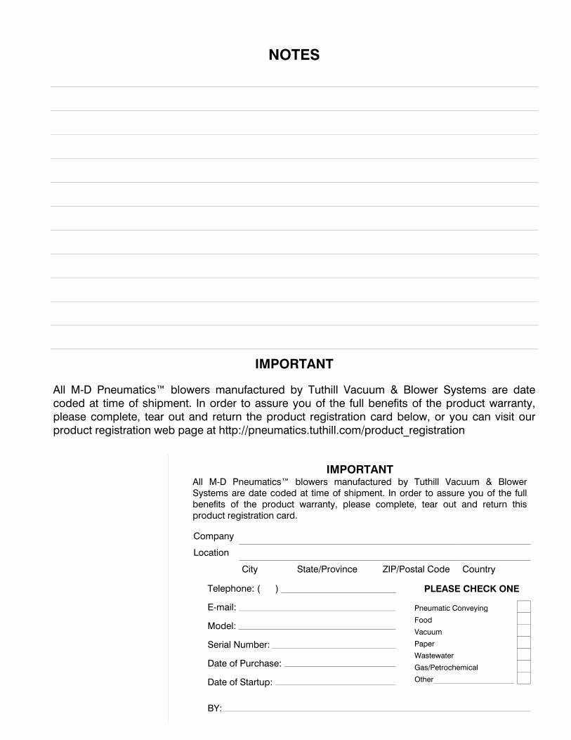
All M-D Pneumatics™ blowers manufactured by Tuthill Vacuum & Blower Systems are date coded at time of shipment. In order to assure you of the full benefits of the product warranty, please complete, tear out and return the product registration card below, or you can visit our product registration web page at http://pneumatics.tuthill.com/product_registration
IMPORTANT All M-D Pneumatics™ blowers manufactured by Tuthill Vacuum & Blower Systems are date coded at time of shipment. In order to assure you of the full benefits of the product warranty, please complete, tear out and return this product registration card.
Company
Location
City State/Province ZIP/Postal Code Country
Pneumatic Conveying
Food
Vacuum
Paper
Wastewater
Gas/Petrochemical
Other
PLEASE CHECK ONE Telephone: ( )
E-mail:
Model:
Serial Number:
Date of Purchase:
Date of Startup:
BY:

NO POSTAGE NECESSARY IF MAILED
IN THE UNITED STATES
BUSINESS REPLY MAIL FIRST-CLASS MAIL PERMIT NO. 2912 SPRINGFIELD MO
POSTAGE WILL BE PAID BY ADDRESSEE
ATTN CUSTOMER SERVICE TUTHILL VACUUM & BLOWER SYSTEMS PO BOX 2877 SPRINGFIELD MO 65890-2150