Embed Size (px)
Citation preview
© Oxford University Press 2013. All rights reserved.
Chapter 13
Pressure Measurements

© Oxford University Press 2013. All rights reserved.
Temperature can be defined as a condition of a body by virtue of which heat istransferred from one system to another.
A comparison between Kelvin, Celsius, and Fahrenheit scales with respect toabsolute zero, and boiling and freezing points of water is shown in Table 15.1.
The scales used to measure temperature can be divided into relative scales[Fahrenheit (°F) and Celsius (°C)] and absolute scales [Rankine (°R) and Kelvin(K)].
The various temperature scales are related as follows:F = 1.8C + 32C = (F − 32)/1.8R = F + 460K = C + 273
Introduction

© Oxford University Press 2013. All rights reserved.
Pressure is the force exerted by a medium, usually a fluid, on a unit area. Measuring devices usually register a differential pressure—gauge pressure.
Pressure is also defined as the force exerted over a unit area. Force may be exerted by liquids, gases, and solids.
Pressure (P) = Force (F)Area (A)
Measurement of pressure becomes an important aspect due to the following reasons:
1. It is a quantity that describes a system.
2. It is invariably a significant process parameter.
3. Many a time, pressure difference is used as a means of measuring the flow rate of a fluid.
4. From the lowest to the highest pressures usually encountered in practice, the level of pressure has a range of nearly 18 orders of magnitude.
Introduction

© Oxford University Press 2013. All rights reserved.
The following are the units and conversion actors that are normally used:
1. 1 Pa = 1 N/m22. 1 atm = 760 mmHg = 1.013 × 10⁵ Pa3. 1 mmHg = 1 Torr4. 1 Torr = 1.316 × 10⁻³ atm = 133.3 Pa5. 1 bar = 105 Pa
Pressure Measurement Scales

© Oxford University Press 2013. All rights reserved.
Methods of Pressure MeasurementPressure measurements can be grouped into two main categories: Static and Dynamic pressures.
Static pressure, as the name implies, is the pressure exerted by a fluid when it is in equilibrium or still or static; pressures acting at a point are the same in all directions and do not depend on the direction.
For measuring pressures that vary rapidly, the methods that are employed for the measurement of static pressure are not suitable (e.g., pressure in the cylinder of an internal combustion engine).
In such cases, pressure transducers are used to convert pressure into signals that are recordable.

© Oxford University Press 2013. All rights reserved.
Static Pressure Measurement The static pressure at any point in the fluid is the pressure exerted by
the height of the fluid above that point, when the fluid is in staticcondition.
If any attempt is made to restore equilibrium due to the existence ofpressure components within a continuous body, the fluid flows fromregions of high pressure to those of lower pressure. In such cases, totalpressures are direction dependent.
Figure 16.2 shows the arrangement of pressure probes at two differentorientations.
These two pressure probes P1 and P2 are placed such that their openingsreceive the impact of the flow.
Methods of Pressure Measurement

© Oxford University Press 2013. All rights reserved.
The results of measurements differ from each other. The pressure probe P1measures static component of the pressure, whereas the pressure probe P2gives stagnation pressure.
It can be mentioned here that the static pressure is the pressure sensed while moving along with the stream, and the pressure obtained if the stream is brought to rest entropically may be referred to as the total pressure.
The difference between the stagnation pressure and the static pressure is known as the dynamic or velocity pressure.
Methods of Pressure Measurement

© Oxford University Press 2013. All rights reserved.
Pressure is usually measured by transducing its effects into deflection using the following types of transducers:
1. Gravitational type: (a) Liquid columns (b) Pistons or loose diaphragms and weights
2. Direct acting elastic type: (a) Unsymmetrical loaded tubes (b) Symmetrically loaded tubes (c) Elastic diaphragms (d) Bellows (e) Bulk compression (f) Indirect acting elastic types:
3. Piston with elastic restraining member
Methods of Pressure Measurement

© Oxford University Press 2013. All rights reserved.
Classification of Pressure Measuring Devices
The different instruments/devices used for the measurement of pressure can be classified as follows:
1. Gravitation‐type manometers2. Mechanical displacement‐type manometers:
(a) Ring balance (b) Bell type
3. Elastic pressure transducers:(a) Bourdon tube pressure gauges (b) Diaphragm‐type gauges(c) Bellow gauges
4. Electrical pressure transducers:(a) Resistance‐type pressure transducer (b) Potentiometer devices(c) Inductive‐type transducer (d) Capacitive‐type transducer(e) Piezoelectric pressure transducer (f) Bridgman gauges
5. Low‐pressure measurement gauges:(a) McLeod gauges (b) Pirani or thermal conductivity gauges(c) Ionization gauges
6. Engine indicator (for varying pressure measurements)
© Oxford University Press 2013. All rights reserved.
Manometers for Pressure Measurement
Manometers have been extensively employed for the measurement of differential pressure.
These are sometimes used as primary standards for pressure measurement.
It is essential to compensate for the deviations due to gravity by location, compressibility of fluid, and capillary effects to attain the precision required for primary standards.
The expansion of the fluid filled in a manometer (due to variation in temperatures) affects their density and, in turn, also the thermal expansion of the read‐out scale, affecting the precision of measurement
Methods of Pressure Measurement

© Oxford University Press 2013. All rights reserved.
Methods of Pressure Measurement
Although manometers have several limitations, they are simple and less expensive, which make them popular.
One of the major disadvantages of manometers is that the filling fluids may vaporize at high vacuum or temperatures.
Other limitations include toxicity of mercury, thermal expansion of fluids and read‐out scales affecting accuracy of measurement, variations of density, corrosion problems, and evaporation of fluids at low‐pressure and high‐temperature conditions

© Oxford University Press 2013. All rights reserved.
Industrial U Tube Manometer An improved U tube manometer is used for the measurement of
high pressures for industrial purposes, which is given in Fig. 16.3.
This type of manometer consists of two limbs, often made of steel, where one limb is of a much larger diameter than the other.
A higher pressure of P1 to the narrow limb having a cross section of A1 and a lower pressure of P2 to the wide limb having a cross section of A2 are applied.
Thus, there exists a differential pressure. It can be observed that the liquid in the wider limb rises and that in the narrow limb falls.
Methods of Pressure Measurement

© Oxford University Press 2013. All rights reserved.
Methods of Pressure Measurement
Thus, it can be seen from above Eq. that the rise of the liquid in the wide limb is proportional to the differential pressure (P1 − P2).

© Oxford University Press 2013. All rights reserved.
Methods of Pressure Measurement
In these types of manometers, a narrow tube is directly inserted into the wide limb. A differential pressure is applied, as shown in Fig. 16.4.
Then P1 − P2 = ρg(h + d)
We know that A1d = A2h and therefore
Cistern Manometer

© Oxford University Press 2013. All rights reserved.
Inclined Tube Manometer An inclined tube manometer comprises two limbs. One of the limbs is a narrow
glass tube that is inclined at an angle q to the horizontal.
The other limb is a cistern, which is of a wider cross section. Assume that the narrow and wider limbs have cross sectional areas of A1 and A2 respectively.
A scale is attached to the sloping limbP1 – P2 = ρgx sinθ.
The inclined tube manometer is an improvement of the conventional U tube manometer.
Methods of Pressure Measurement

© Oxford University Press 2013. All rights reserved.
Methods of Pressure Measurement
We have x sinθ = h from Fig. 16.5. If the tube is inclined at an angle of 30° to the horizontal, then sinθ = sin 30° = ½.
Therefore, x = 2h, which means that a scale length of twice the normal value is obtained by inclining the tube at an angle of 30° to the horizontal.
Hence, it can be seen that an inclined manometer has the advantage of an increased length of scale

© Oxford University Press 2013. All rights reserved.
Ring Balance
The ring balance belongs to mechanical displacement‐type pressure measuring devices.
It is composed of an annular ring, which is separated into two parts by a partition. The lower section of the annular ring is also filled with a sealing fluid (either water or mercury).
The ring is balanced on a knife edge at its centre so that it is free to rotate. A mass to compensate the difference in pressure is attached to the lower part of the ring.
In the ring balance illustrated in Fig. 16.6, P1 and P2 represent high and low pressures, respectively.
Methods of Pressure Measurement

© Oxford University Press 2013. All rights reserved.
Methods of Pressure Measurement
© Oxford University Press 2013. All rights reserved.
Inverted Bell Manometer
An inverted bell manometer is another pressure measuring device that is of the mechanical displacement type.
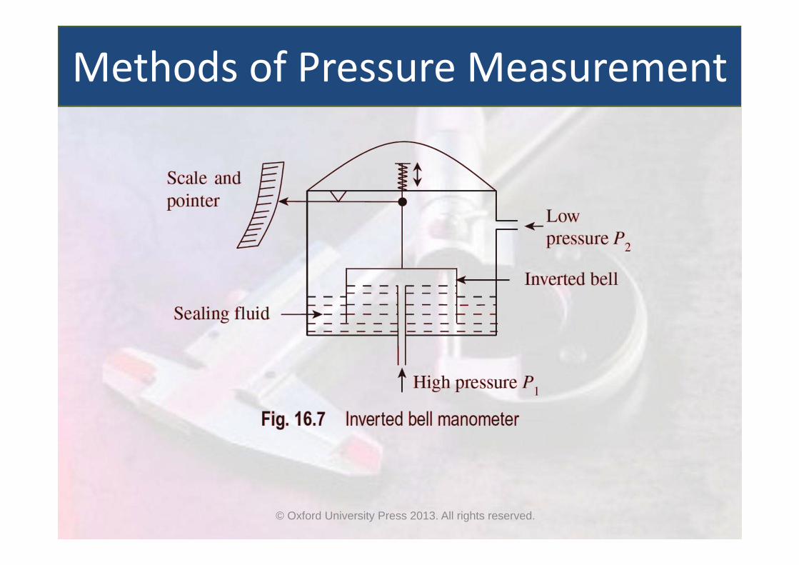
Figure 16.7 shows the working principle of an inverted bell manometer. In this, as the name suggests, the bell is immersed in the sealing fluid in an upside‐down position.
The inverted bell moves in the vertical direction due to the differential pressure arising out of the pressure difference between the interior and exterior surfaces of the bell.
A spring provided on top of the inverted bell balances the vertical motion of the bell due to a pressure difference or by the weight of the bell.
Methods of Pressure Measurement
© Oxford University Press 2013. All rights reserved.
Methods of Pressure Measurement

© Oxford University Press 2013. All rights reserved.
The vertical movement of the bell can be translated into a pointer movement with the help of a linkage system.
A variable reluctance pickup can be employed, which converts the vertical motion of the bell to an electrical signal instead of a spring.
The inverted bell manometer will measure the absolute pressure if the lower‐pressure side is connected to a vacuum line with an appropriate sealing fluid.
The displacement of the bell is a linear function of differential pressure.
Methods of Pressure Measurement
© Oxford University Press 2013. All rights reserved.
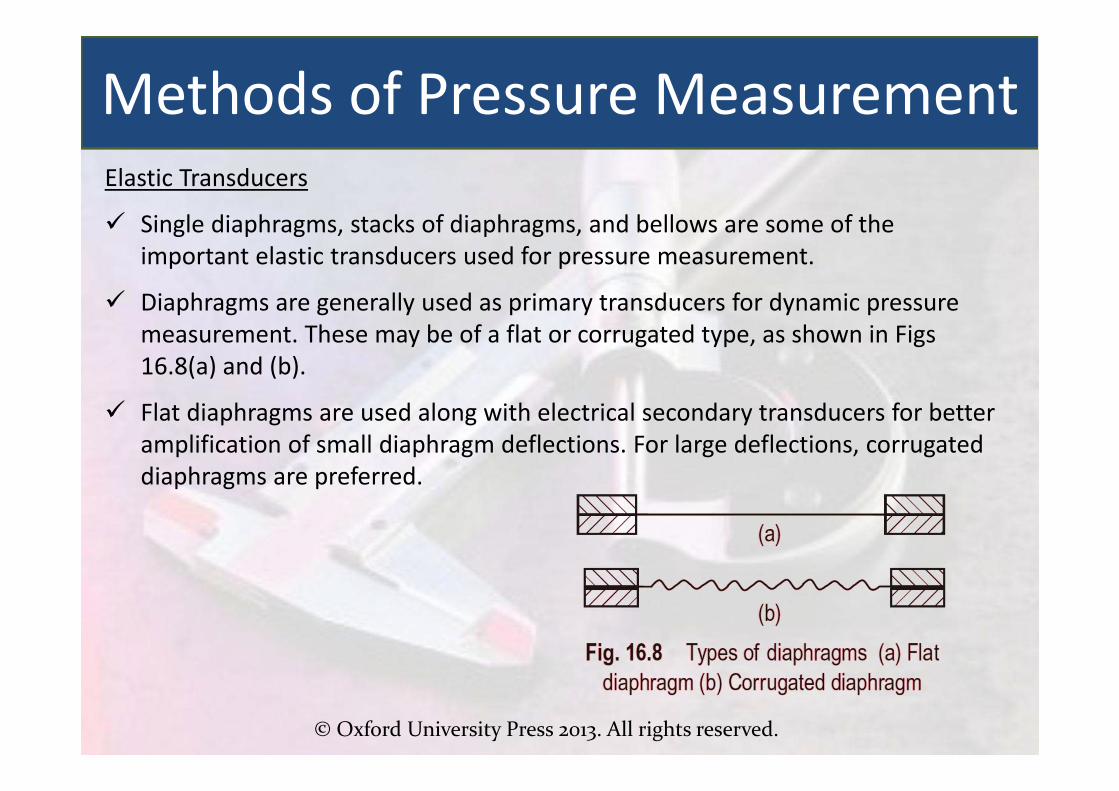
Elastic Transducers
Single diaphragms, stacks of diaphragms, and bellows are some of the important elastic transducers used for pressure measurement.
Diaphragms are generally used as primary transducers for dynamic pressure measurement. These may be of a flat or corrugated type, as shown in Figs 16.8(a) and (b).
Flat diaphragms are used along with electrical secondary transducers for better amplification of small diaphragm deflections. For large deflections, corrugated diaphragms are preferred.
Methods of Pressure Measurement

© Oxford University Press 2013. All rights reserved.
Methods of Pressure Measurement
A single diaphragm in its simplest form is shown in Fig. 16.9.
It is a thin, flat, circular plate fixed at the two ends; upon application of pressure, it will deflect as shown in Fig. 16.9, and the resulting differential pressure is given by P1 − P2.

© Oxford University Press 2013. All rights reserved.
Sometimes, a mechanical linkage system or an electrical secondary transducer needs to be connected to the diaphragm at its centre.
To enable this, a metal disc or any other rigid material is provided at the centre with diaphragms on either side.
This type of transducer, which is used for pressure measurement, is known as the slack diaphragm or fabric diaphragm differential pressure gauge. Construction of a fabric diaphragm is shown in Fig. 16.10.
It comprises a rigid centre piece, which is held on either side by diaphragms made of fabric.
A secondary transducer, which may be an electrical or a mechanical linkage system, or a recording pen, is connected at the centre (as shown in Fig. 16.10). The slack diaphragm is used to measure low pressures.
Since the centre piece is rigid, there may be a reduction in flexibility of the diaphragm.

© Oxford University Press 2013. All rights reserved.
A pressure capsule or a metal capsule can be formed by joining two or more diaphragms, as shown in Fig. 16.11.
Use of corrugated diaphragms increases linear deflections and reduces stresses. It can be seen from Fig. 16.11 that differential pressure can be created by applying one pressure from inside the capsule and another from the outside.
In a metallic capsule, the relationship between deflection and pressure remains linear as long as the movement is not excessive.
Metallic bellows can be employed as pressure‐sensing elements. A thin‐walled tube is converted into a corrugated diaphragm by using a hydraulic press and is stacked as shown in Fig. 16.12. Due to the differential pressure, there will be a deflection, y0.
Metallic bellows are often associated with zero shift and hysteresis problems.

© Oxford University Press 2013. All rights reserved.
Modification of a metallic bellow for differential pressure measurement is shown in Fig. 16.13.
An industrial gauge, called an industrial bellows gauge, has a double‐bellow arrangement.
One end of the double bellow is connected to a pointer or a recorder pen.
A high pressure of P2 and a low pressure of P1 are applied to create a differential pressure as shown in Fig. 16.13.

© Oxford University Press 2013. All rights reserved.
The most widely used gauge for pressure measurement is the Bourdon tube. This tube is composed of a C‐shaped hollow metal tube having an elliptical cross section.
One end of the Bourdon tube is fixed and can be used as the pressure inlet, as shown in Fig. 16.14.
The other end is free and closed. Due to the applied pressure, the tube straightens out and tends to acquire a circular cross section.
Thus, pressure causes the free end to move. This movement is proportional to the difference between inside and outside pressures.
To measure pressure, movement of the free end is often magnified and transmitted to a pointer that moves over the scale through a linkage and gearing mechanism.
The pointer indicates gauge pressure, since the reference pressure is atmospheric.

© Oxford University Press 2013. All rights reserved.
In case higher sensitivity is required, the Bourdon tube may be formed into a helix containing several turns.
Bourdon tubes are usually made of phosphor bronze, brass, and beryllium copper.
Bourdon gauges are employed to measure pressures of up to 500 MPa.

© Oxford University Press 2013. All rights reserved.
Electrical Pressure Transducers
Electrical pressure transducers translate mechanical output into electrical signals in conjunction with elastic elements such as bellows, diaphragms, and Bourdon tubes.
The mechanical displacement is first converted into a change in electrical resistance, which is then converted into an electrical signal, that is, change in either current or voltage.
Electric pressure transducers are preferred over mechanical devices because of their quick response, low hysteresis, better linearity properties, and high accuracy in digital measurement systems.
Electrical pressure transducers are classified as follows: 1. Resistance‐type transducer2. Potentiometer devices3. Inductive‐type transducer4. Capacitive‐type transducer5. Piezoelectric pressure transducer
Electrical Transducers
© Oxford University Press 2013. All rights reserved.
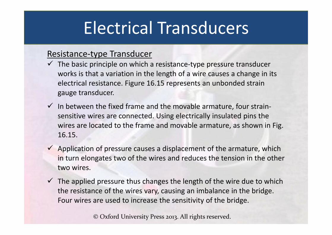
Resistance‐type Transducer The basic principle on which a resistance‐type pressure transducer
works is that a variation in the length of a wire causes a change in its electrical resistance. Figure 16.15 represents an unbonded strain gauge transducer.
In between the fixed frame and the movable armature, four strain‐sensitive wires are connected. Using electrically insulated pins the wires are located to the frame and movable armature, as shown in Fig. 16.15.
Application of pressure causes a displacement of the armature, which in turn elongates two of the wires and reduces the tension in the other two wires.
The applied pressure thus changes the length of the wire due to which the resistance of the wires vary, causing an imbalance in the bridge. Four wires are used to increase the sensitivity of the bridge.
Electrical Transducers

© Oxford University Press 2013. All rights reserved.
Electrical Transducers
© Oxford University Press 2013. All rights reserved.
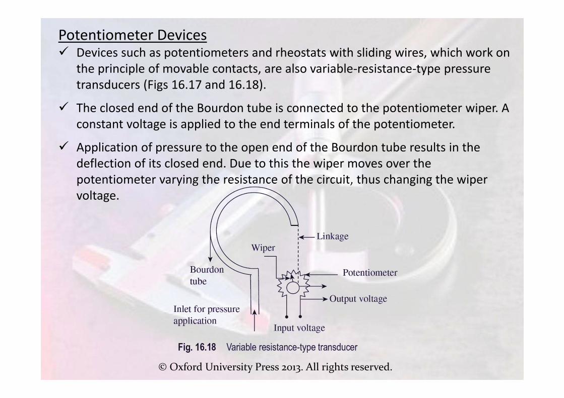
Potentiometer Devices Devices such as potentiometers and rheostats with sliding wires, which work on
the principle of movable contacts, are also variable‐resistance‐type pressure transducers (Figs 16.17 and 16.18).
The closed end of the Bourdon tube is connected to the potentiometer wiper. A constant voltage is applied to the end terminals of the potentiometer.
Application of pressure to the open end of the Bourdon tube results in the deflection of its closed end. Due to this the wiper moves over the potentiometer varying the resistance of the circuit, thus changing the wiper voltage.

© Oxford University Press 2013. All rights reserved.
Inductive‐type Transducer The linear variable differential transformer (LVDT) is an inductive type of
pressure transducer that works on the mutual inductance principle.
It transforms a mechanical displacement into an electrical signal. The magnetic core is connected to an elastic pressure transducer like a Bourdon tube.
The Bourdon tube senses the applied pressure and converts it into displacement, which in turn moves the core of the LVDT.
An LVDT comprises one primary and two secondary windings (coils), which are mounted on a common frame, as shown in Fig. 16.19. The three coils are carefully wound on an insulated bobbin.
On either side of the primary coil, which is centrally placed, two secondary windings are symmetrically placed.
A non‐contacting magnetic core moves in the centre of these coils, which are wound on the insulating bobbin.
The core, which is made from a uniformly dense cylinder of a nickel–iron alloy, is carefully annealed to enhance and homogenize its magnetic permeability.
It is centrally positioned between the secondary windings.

© Oxford University Press 2013. All rights reserved.
When the core is in this position, the induced voltages in the two secondary windings are equal and 180° out of phase, which is taken as the zero position as illustrated in Fig. 16.20.
The displacement of core from the zero position due to the applied pressure increases the induced voltage in one of the secondary windings while the voltage in the other decreases.
Due to this, the differential voltage, which appears across the two secondary windings, is approximately linear for small core displacements and is hence a measure of applied pressure.
© Oxford University Press 2013. All rights reserved.
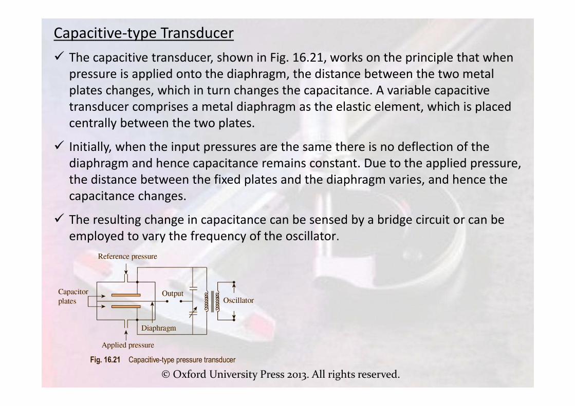
Capacitive‐type Transducer The capacitive transducer, shown in Fig. 16.21, works on the principle that when
pressure is applied onto the diaphragm, the distance between the two metal plates changes, which in turn changes the capacitance. A variable capacitive transducer comprises a metal diaphragm as the elastic element, which is placed centrally between the two plates.
Initially, when the input pressures are the same there is no deflection of the diaphragm and hence capacitance remains constant. Due to the applied pressure, the distance between the fixed plates and the diaphragm varies, and hence the capacitance changes.
The resulting change in capacitance can be sensed by a bridge circuit or can be employed to vary the frequency of the oscillator.

© Oxford University Press 2013. All rights reserved.
Piezoelectric‐type Transducer A piezoelectric pressure transducer is an active type
of pressure transducer, which works on the principlethat when pressure is applied on piezoelectriccrystals an electric charge is produced.
A piezoelectric pressure transducer (as shown in Fig.16.22) comprises a corrugated metal diaphragm onwhich pressure is applied. Deflection of thediaphragm is transmitted to the piezoelectric crystalthrough a mechanical link. The piezoelectric crystalis capable of producing the maximum piezoelectricresponse in one direction and minimum responsesin other directions.
Thus, the piezoelectric crystal senses the appliedpressure and generates a voltage proportional tothe applied pressure. The generated voltage can bemeasured using a calibrated output voltage‐measuring instrument, which gives a measure of theapplied pressure.

© Oxford University Press 2013. All rights reserved.
Varying Pressure Measurement Measurement of variation of pressure is normally simple, especially when the
pressure changes slowly. The variation in pressure can be monitored by taking readings periodically.
When variation in pressure occurs rapidly, complexity in measurement also increases and static pressure measuring devices will no longer be useful. In fact, when the rate of pressure change increases, it becomes increasingly difficult to take readings, necessitating the use of high‐speed recording devices.
Engine Indicator In order to measure the cylinder pressure in a reciprocating machine, such as an
internal combustion engine or an air compressor, it is essential to plot a graph of cylinder pressure versus cylinder volume or time.
An engine indicator illustrated in Fig. 16.23(a) is composed of a small cylinder whose size is known and operates against a spring through which the operating range can be set.
An engine indicator records the cylinder pressure corresponding to the piston movement. The drum contains a piece of paper or card on its outer surface on which the simultaneous variation of pressure and cylinder volume is recorded.

© Oxford University Press 2013. All rights reserved.
The rotating drum is designed to provide a reciprocating movement proportional to the engine piston movement in the cylinder.
The stylus moves up and down, the movement being proportional to the pressure in the small cylinder located at the base of the indicator, which is connected to the engine cylinder.
The movement of the piston is transferred to a rotating drum through a magnetic lever and an indicator diagram can be obtained (Fig. 16.23 b).

© Oxford University Press 2013. All rights reserved.
Dead-weight Pressure GaugeA dead-weight pressure gauge or piston gauge is a very popular device formeasuring static pressure. It works on Archimedes’ principle.
The air or fluid displaced by the applied weights and the piston exerts a buoyantforce, which causes the gauge to indicate the pressure.
Dead-weight pressure gauges are normally used to calibrate other pressuremeasuring devices. A dead-weight tester, shown in Fig. 16.24, is a device used forbalancing a fluid pressure with a known weight.
where Fe is the equivalent force ofthe piston and weight combination,Ae the equivalent area of thepiston and cylinder combination,and Pdw the dead-weight pressure.
Pdw =

© Oxford University Press 2013. All rights reserved.
Pressures below atmosphere are generally termed as low pressures or vacuum pressures. When the term vacuum is mentioned it means that the gauge pressure is negative.
However, atmospheric pressure serves as a reference and absolute pressure is positive. Low pressures are more difficult to measure than medium pressures.
For measuring pressures below 1 Torr, indirect or inferential methods are often employed. In these methods, pressure is determined by drawing indirect references to pressure‐controlling properties such as volume, thermal conductivity, and ionization of gas.
Some of the devices that fall under this category include McLeod gauge, Pirani gauge, and ionization gauge.
Measurement of Vacuum

© Oxford University Press 2013. All rights reserved.
McLeod Gauge
McLeod gauge, is perhaps the most widely used. It is employed as an absolute standard of vacuum measurement for pressures ranging from 10 to 10−4 Torr.
A McLeod gauge, which is also known as a compression gauge, is used for vacuum measurement by compressing the low‐pressure gas whose pressure is to be measured.
The trapped gas gets compressed in a capillary tube. Vacuum is measured by measuring the height of a column of mercury.
Measurement of Vacuum

© Oxford University Press 2013. All rights reserved.
Measurement of Vacuum McLeod gauge works on Boyle’s law, which states that by compressing a
known volume of the low‐pressure gas to a higher pressure, initial pressure can be calculated by measuring the resulting volume and pressure.
The following fundamental relation represents Boyle’s law:
where P1 and P2 are the initial and final pressures, respectively, and V1 and V2 are the corresponding volumes.
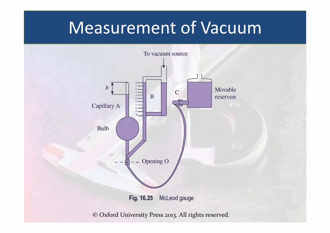
A McLeod gauge is composed of a capillary tube A, which is sealed at the top, and two limbs B and C, which are connected to the vacuum system. Both limbs A and B are capillary tubes and their diameters are the same.

© Oxford University Press 2013. All rights reserved.
The diameter of limb C is wider and hence reduces capillary errors. The McLeod gauge is schematically represented in Fig. 16.25.
Let V1 be the volume of the bulb in capillary A above the level O, P1 the unknown pressure of the gas in the system connected to B and C, P2 the pressure of the gas in the limb after compression, and V2 the volume of the gas in the sealed limb after compression. Then,
In order to measure low pressures, the value of V1 is made large compared to that of a. The ratio of V1 to a is called the compression ratio.
If a is made too small, the mercury tends to stick inside the capillary tube; this imposes a restriction on the upper limit of the compression ratio. The compression ratio gets limited due to the excessive weight of mercury if V1 is very large.
McLeod gauges are regularly employed to calibrate other high‐vacuum measuring devices.The presence of condensable vapours in the gas whose pressure is to be measured poses a serious limitation as Boyle’s law is not followed, which may induce errors.
© Oxford University Press 2013. All rights reserved.
Measurement of Vacuum
© Oxford University Press 2013. All rights reserved.
Pirani Gauge The principle on which a Pirani gauge (shown in Fig. 16.26) works is thus: when a
heated wire is placed in a chamber of gas, thermal conductivity of the gas depends on its pressure. Hence, it follows that energy transfer from the wire to the gas is proportional to the gas pressure.
The temperature of the wire can be altered by keeping the heating energy supplied to the wire constant and varying the pressure of the gas, thus providing a method for pressure measurement.
On the other hand, a change in the temperature of the wire causes a change in the resistance, providing a second method for the measurement of pressure.
A resistance bridge is employed when the resistance of the wire filament is measured. The bridge is balanced at some reference pressure and the out‐of‐balance currents are used at all other pressures as a measure of the relative pressures.
Measurement of Vacuum

© Oxford University Press 2013. All rights reserved.
Heat loss from the filament due to the variations in ambient temperatures can be compensated. This can be accomplished by connecting the two gauges in series in one arm of the bridge, as depicted in Fig. 16.27.
One of the gauges whose pressure is to be measured is connected to a vacuum source and the other is evacuated and sealed.
Since both are exposed to the same ambient conditions, the measurement gauge will respond only to variations in the vacuum pressure. By adjusting R2, the bridge circuit can be balanced to give a null reading.
Measurement of Vacuum

© Oxford University Press 2013. All rights reserved.
Ionization Gauge Ionization gauges are employed for medium‐ and high‐vacuum measurements.
These gauges convert neutral gas molecules into positively charged or ionized gas molecules.
This gauge is also known as thermionic gauge as electrons are emitted from a heated filament or substance. These emitted electrons are called thermions. The principle of thermionic emission is employed in electron vacuum tubes.
When the tungsten filament is heated to a high temperature, electrons acquire sufficient energy and move into the space.
In a hot cathode ionization gauge, electrons emitted from the thermionic cathode can be accelerated in an electric field. These electrons collide with gas molecules and ionize them.
The thermionic triode arrangement in an ionization gauge comprises an anode and a cathode encompassed in a glass envelope, which may be connected to the source whose pressure is required to be measured.
Measurement of Vacuum

© Oxford University Press 2013. All rights reserved.
The anode and grid are at negative and positive potentials respectively, with reference to the filament. Gas molecules collide with the electrons emitted from the heated filament (cathode) and become ionized. Positive ions then move towards the negatively charged anode.
Thus, an ionization current flows through the circuit, which is a measure of the absolute gas pressure in the gauge. Eventually, the electrons will move towards the positively biased grid, forming an electron current around the grid circuit.
Measurement of Vacuum

© Oxford University Press 2013. All rights reserved.
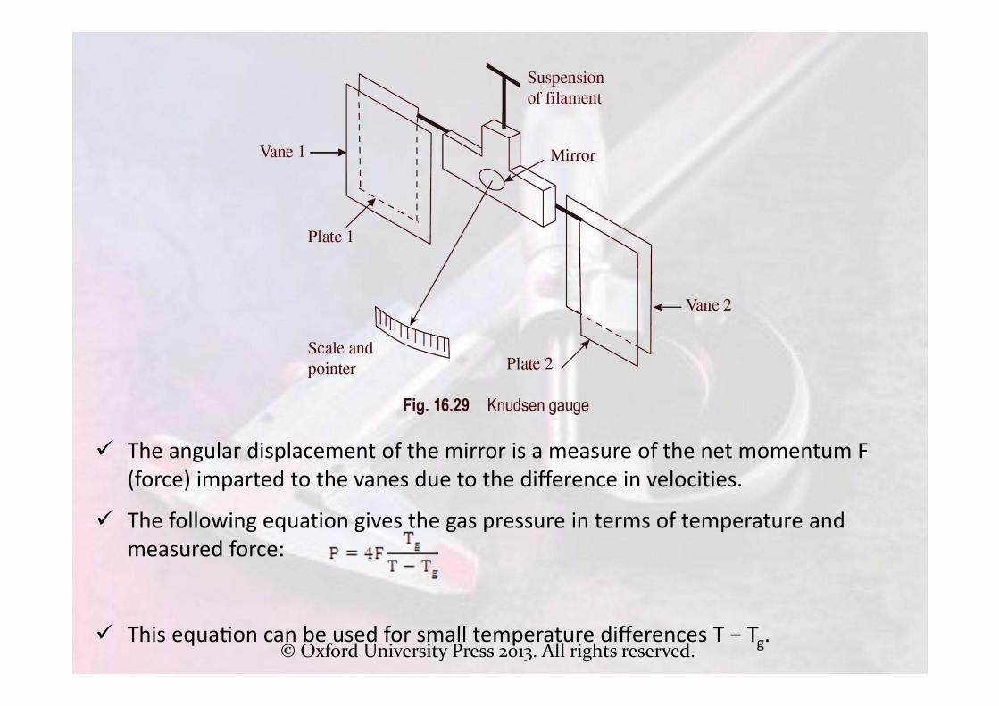
Knudsen Gauge
Knudsen gauge, shown in Fig. 16.29, is a device employed to measure very low pressures. Pressure is measured as a function of the net rate of exchange of momentum of molecular density between vanes and hot plates, which are at different temperatures.
This in turn can be correlated to the pressure and temperature of the gas. Knudsen gauges are suitable for pressures ranging between 1 and 10−6 Pa.
A Knudsen gauge is composed of two vanes V1 and V2 and a mirror, which are mounted on a thin filament suspension.
Measurement of Vacuum

© Oxford University Press 2013. All rights reserved.
Measurement of Vacuum Two heated plates P1 and P2, which are maintained at a
temperature T, are placed near the vanes.
The vanes and plates are so placed that the distance between them is less than the mean free path of the surrounding gas whose pressure is to be measured.
The plates are maintained at a temperature higher than that of the surrounding gas by installing heaters. Let the temperature of the vanes be Tg.
Due to the difference in temperature, the gas molecules strike the cooler vanes. These molecules have a higher velocity than those leaving the vanes, as per the kinetic theory of gases.
© Oxford University Press 2013. All rights reserved.
The angular displacement of the mirror is a measure of the net momentum F (force) imparted to the vanes due to the difference in velocities.
The following equation gives the gas pressure in terms of temperature and measured force:
This equa on can be used for small temperature differences T − Tg.

© Oxford University Press 2013. All rights reserved.
High‐pressure Measurement High‐pressure measurement necessitates the use of special devices. The
most popular device used is the Bridgman gauge, which is capable ofmeasuring high pressures of around 100,000 atm.
Bridgman gauge works on the principle that the resistance of a fine wirelinearly varies with pressure. The applied pressure is sensed using a finewire of Manganin (84% Cu, 12% Mn, and 4% Ni) having a total resistance of100 Ω, loosely wound on a coil, and enclosed in a container havingappropriate pressure.
Conventional bridge circuits are employed for measuring the change inresistance, which is calibrated in terms of the applied pressure and is givenby the following equation:
R = R1 (1 + PrΔP)
High Pressure Measurement
© Oxford University Press 2013. All rights reserved.
where R1 is the resistance at 1 atm, Pr the pressure coefficient of resistance, and ΔP the gauge pressure.
A Bridgman gauge requires frequent calibration, as ageing is a problem. A properly calibrated gauge can be used to measure high pressures with an accuracy of 0.1%.
Since the Bridgman gauge has a very good transient response, changes with application of pressure are sensed almost instantaneously.
High Pressure Measurement


![Civil Engineering Department - ack.edu.kw · 10. 15FCVE124 – Fluid Mechanics [ 3CH, 3 Lec, 2 Lab ] Fluid mechanics covers properties of fluids, manometers and pressure measurement,](https://img.dokumen.tips/doc/110x75/5e15c5b87883c13f891096fb/civil-engineering-department-ackedukw-10-15fcve124-a-fluid-mechanics-3ch.jpg)


![Engineering Metrology - Islamic University of Gazasite.iugaza.edu.ps/aabuzarifa/files/MET20172_CH0.pdf · Microsoft PowerPoint - MET20172_CH0.ppt [Compatibility Mode] Author: aabuzarifa](https://img.dokumen.tips/doc/110x75/5fcf3dc46f06fe47c633a68b/engineering-metrology-islamic-university-of-microsoft-powerpoint-met20172ch0ppt.jpg)