Embed Size (px)
Citation preview

Venous Access | Critical Care
Pressure Injectable PICC Product
A06041102D0.indd iA06041102D0.indd i 6/4/2008 11:18:50 AM6/4/2008 11:18:50 AM

Arrow International, Inc.© 2008 Arrow International, Inc. All rights reserved. Printed in the USA. An issued or revision date for these instructions is included for user information. In the event two years have elasped between this date and product use, the user should contact Arrow International, Inc. to see if additional product information is available.Revised Date: June 2008Rx only.
A06041102D0.indd iiA06041102D0.indd ii 6/4/2008 11:19:22 AM6/4/2008 11:19:22 AM

PI PICC | iii
Table of Contents
Product Description 1
Indications / Contraindications . . . . . . . . . . . . . . . . . . . . . . . . 1
Pressure Injection 1
Warnings and Precautions . . . . . . . . . . . . . . . . . . . . . . . . . . 1
Pressure Injection Procedure . . . . . . . . . . . . . . . . . . . . . . . . . 1
Peripherally Inserted Central Catheter Warnings and Precautions 2
General . . . . . . . . . . . . . . . . . . . . . . . . . . . . . . . . . . 2
Catheter . . . . . . . . . . . . . . . . . . . . . . . . . . . . . . . . . . 3
Placement Wire & Guidewire . . . . . . . . . . . . . . . . . . . . . . . . . 4
Tissue Dilator . . . . . . . . . . . . . . . . . . . . . . . . . . . . . . . . 4
Peel-Away Sheath over Tissue Dilator . . . . . . . . . . . . . . . . . . . . . 4
Possible Complications . . . . . . . . . . . . . . . . . . . . . . . . . . . 4
Accessory Component Instructions 4
Catheter Stabilization Device . . . . . . . . . . . . . . . . . . . . . . . . . 4
Catheter Trimmer . . . . . . . . . . . . . . . . . . . . . . . . . . . . . . 5
Dressing . . . . . . . . . . . . . . . . . . . . . . . . . . . . . . . . . . 6
Echogenic Needle . . . . . . . . . . . . . . . . . . . . . . . . . . . . . . 6
Filter Straw . . . . . . . . . . . . . . . . . . . . . . . . . . . . . . . . . 7
Guidewire / SWG Insertion Techniques . . . . . . . . . . . . . . . . . . . . 7
80 cm . . . . . . . . . . . . . . . . . . . . . . . . . . . . . . . . . 7
130 cm . . . . . . . . . . . . . . . . . . . . . . . . . . . . . . . . . 7
Maximal Barrier Drape . . . . . . . . . . . . . . . . . . . . . . . . . . . . 7
Positive Displacement Valve . . . . . . . . . . . . . . . . . . . . . . . . . 8
Protected Needle . . . . . . . . . . . . . . . . . . . . . . . . . . . . . . 9
SharpsAway II™ Locking Disposal Cup . . . . . . . . . . . . . . . . . . . . . 9
Pre-PICC Insertion & Patient Assessment Activities 10
Procedural Pause . . . . . . . . . . . . . . . . . . . . . . . . . . . . . . 10
Preparing for PICC Insertion . . . . . . . . . . . . . . . . . . . . . . . . . 10
For reference literature concerning patient assess-ment, clinician education, insertion techniques and potential complications associated with central venous access refer to Arrow International, Inc. website: www.arrowintl.com
For convenience, procedural and general Warnings and Precautions are listed at the beginning of the instructions. Please review all content before performing the procedure.
A06041102D0.indd iiiA06041102D0.indd iii 6/4/2008 11:19:22 AM6/4/2008 11:19:22 AM

iv | PI PICC
Prep Puncture Site . . . . . . . . . . . . . . . . . . . . . . . . . . . . 10
Prepare All Equipment . . . . . . . . . . . . . . . . . . . . . . . . . . 10
Trim Catheter . . . . . . . . . . . . . . . . . . . . . . . . . . . . . . 11
Flush Catheter . . . . . . . . . . . . . . . . . . . . . . . . . . . . . . 11
Catheter Insertion Instructions 11
Gain Initial Venous Access . . . . . . . . . . . . . . . . . . . . . . . . . . 11
Sheath Placement . . . . . . . . . . . . . . . . . . . . . . . . . . . . . . 12
Catheter Advancement . . . . . . . . . . . . . . . . . . . . . . . . . . . 12
Placement Wire . . . . . . . . . . . . . . . . . . . . . . . . . . . . . . . 12
Verify Catheter Tip Placement . . . . . . . . . . . . . . . . . . . . . . . . 12
Complete Catheter Insertion . . . . . . . . . . . . . . . . . . . . . . . . . 12
Documentation 13
Care and Maintenance 13
Dressing . . . . . . . . . . . . . . . . . . . . . . . . . . . . . . . . . . 13
Maintain Catheter Patency . . . . . . . . . . . . . . . . . . . . . . . . . . 13
Catheter Removal 14
A06041102D0.indd ivA06041102D0.indd iv 6/4/2008 11:19:22 AM6/4/2008 11:19:22 AM

| 1
Pressure Injectable Peripherally Inserted Central Catheter (PICC) ProductProduct DescriptionTh e Arrow® Pressure Injectable PICC is a peripherally inserted central venous catheter (PICC) manufactured with medical grade, fl exible polyurethane. Th e Arrow® PICC has a non-tapered catheter body with either a blunt tip or a Blue FlexTip® that is softer than a cut tip with a contour design to enhance maneuverability. Th e Blue FlexTip® also provides visual confi rmation of an intact catheter upon removal. Th e kit components assist the clinician in maintaining maximal sterile barrier precautions.
Indications:Th e Pressure Injectable PICC is indicated for short or long term peripheral access to the central venous system for intravenous therapy, blood sampling, infusion, and power injection of contrast media. Th e maximum pressure of power injector equipment used with the pressure injectable PICC may not exceed 300 psi.
Contraindications:Th is device is contraindicated wherever there is presence of device related infections, previous or current thrombosis. Clinical assessment of patient must be completed to ensure no contraindications exists.
Pressure Injection Warnings and Precautions:Warnings:
Assess each patient for appropriateness of a power
injection procedure.
Power injection procedures must be performed by trained
personnel well versed in safe technique and potential
complications.
Use an appropriate method to confi rm catheter tip
position prior to each pressure injection per institutional
policy.
Ensure patency of catheter prior to power injection
to minimize the risk of catheter failure and/or patient
complications.
Discontinue power injections at fi rst sign of infi ltration /
extravasation. Follow hospital protocol for appropriate
medical intervention.
Cautions: Do not exceed the maximum pressure of 300 psi on power
injector equipment to minimize the risk of catheter failure
and/or tip displacement.
Do not exceed the catheter’s maximum recommended
fl ow rate located on product labeling to minimize the risk
of catheter failure and/or tip displacement.
1.
2.
3.
4.
5.
1.
2.
Warm contrast media to body temperature prior to power
injection to minimize the risk of catheter failure.
Pressure limit settings on power injector equipment may
not prevent over pressurization of an occluded catheter.
Use an appropriately rated 60 inch pressure tubing
between catheter and power injector equipment to
minimize the risk of catheter failure.
Follow the specifi ed contrast media manufacturer’s
instructions for use, warnings, precautions, and
contraindications.
Pressure Injection Procedure:NOTE: Clinicians should use sterile technique when fl ushing, disconnecting, connecting, and replacing injection/needless caps.
1. Use an appropriate method to confi rm each tip placement prior to each pressure injection per institutional policy.
2. Remove injection cap from the lumen of catheter to be injected.3. Check for catheter patency:
Attach 10 mL syringe, or larger, fi lled with sterile normal saline.Aspirate catheter until approximately 3 mL of blood enters syringe freely.Vigorously fl ush catheter.
Warning: Ensure catheter patency prior to pressure injection to minimize the risk of catheter failure and/or patient complications.
4. Detach syringe.5. Attach power injection equipment and extension tubing to lumen
of catheter according to manufacturer’s recommendations.Caution: To minimize risk of catheter failure and/or
tip displacement: • Do not exceed the maximum pressure of 300 psi
on power injector equipment. • Do not exceed the catheter’s maximum recommended
fl ow rate located on product labeling.
6. Inject contrast media in accordance with hospital protocol.Caution: Warm contrast media to body temperature prior to power
injection to minimize the risk of catheter failure.
7. Disconnect catheter from power injector equipment.8. Flush catheter with a 10 mL syringe, or larger, fi lled with sterile
normal saline.9. Replace sterile injection cap on catheter.NOTE: Catheter testing included 10 pressure injection cycles.
3.
4.
5.
6.
•
•
•
A06041102D0.indd Sec1:1A06041102D0.indd Sec1:1 6/4/2008 11:19:22 AM6/4/2008 11:19:22 AM

2 |
Peripherally Inserted Central Catheter Warnings and Precautions:Do not place the catheter into or allow it to remain in the right
atrium or right ventricle (refer to Figure 1).
Figure 1
General Warnings and PrecautionsWarnings:
Prior to use read all package insert warnings, precautions,
and instructions. Failure to do so may result in severe
patient injury or death.
Practitioners must be aware of complications associated
with central vein catheters including but not limited to:
cardiac tamponade secondary to vessel wall, atrial or
ventricular perforation, pleural and mediastinal injuries,
air embolism, catheter embolism, catheter occlusion,
thoracic duct laceration, bacteremia, septicemia,
thrombosis, inadvertent arterial puncture, nerve damage,
hematoma, hemorrhage, and dysrhythmias.
Practitioners must be aware of clinical conditions that may
limit use of PICCs including but not limited to: dermatitis,
cellulitis, and burns at or about the insertion site, previous
ipsilateral venous thrombosis, radiation therapy at or
about insertion site, contractures, mastectomy, and
potential use for AV fi stula.
Do not place central venous catheter (CVC) or peripherally
inserted central catheter (PICC) into or allow them to
remain in the right atrium or right ventricle. X-ray exam or
other method in compliance with hospital protocol must
show catheter tip located in right side of mediastinum
in the SVC (superior vena cava) above its junction with
right atrium and parallel to vessel wall and its distal tip
positioned at a level above either azygos vein or carina
of the trachea, whichever is better visualized. Although
cardiac tamponade secondary to pericardial eff usion is
uncommon, there is a high mortality rate associated with
it. Improper advancement of guidewire into the heart has
also been implicated in causing cardiac perforation and
tamponade.
1.
2.
3.
4.
Ensure catheter tip has not entered the heart or no longer
lies parallel to vessel wall by performing an x-ray exam
or other method in compliance with hospital protocol. If
catheter position has changed, immediately re-evaluate.
Practitioners must be aware of the potential for
entrapment of guidewire by any implanted device in
circulatory system (i.e., vena cava fi lters, stents). Review
patient’s history before catheterization procedure to
assess for possible implants. Care should be taken
regarding length of guidewire inserted. It is recommended
that if patient has a circulatory system implant, catheter
procedure be done under direct visualization to minimize
the risk of guidewire entrapment.
Catheter tip must be located in central circulation when
administering > 10% glucose solution, total parenteral
nutrition, continuous vesicant therapy, infusates with
pH less than 5 or greater than 9, and infusates with an
osmolality above 600 mOsm/L, or any medication known
to be irritating to vessels proximal to the vena cava.
Infusion of incompatible drugs through a non “staggered
port” may cause precipitation.
Be aware of the risk of chemically induced thrombo-
phlebitis when catheter is placed with distal end located
in a vessel proximal to the SVC.
Do not leave open needles or uncapped, unclamped
catheters in central venous puncture site. Air embolism
can occur with these practices.
Use only securely tightened Luer-Lock connections
with any Central Venous Access Device (CVAD) to guard
against inadvertent disconnect.
Use Luer-Lock connectors to help guard against air
embolism and blood loss.
Cautions: The product is designed for single use only.
Do not resterilize or reuse.
Do not use if package has been previously opened or
damaged.
Do not alter the catheter, guidewire, or any other kit/set
component during insertion, use, or removal (except as
instructed).
Procedure must be performed by trained personnel well
versed in anatomical landmarks, safe technique, and
potential complications.
Assess patient for heparin sensitivity. Heparin-induced
thrombocytopenia (HIT) has been reported with the use
of heparin fl ush solutions.
Do not routinely apply prophylactic topical antimicrobial
or antiseptic ointment or cream to the insertion site of
peripheral venous catheters because of the potential
5.
6.
7.
8.
9.
10.
11.
12.
1.
2.
3.
4.
5.
6.
7.
A06041102D0.indd Sec1:2A06041102D0.indd Sec1:2 6/4/2008 11:19:22 AM6/4/2008 11:19:22 AM
PI PICC | 3
risk to promote fungal infections and antimicrobial
resistance.
Temporarily shut off remaining port(s) through which
solutions are being infused before blood sampling.
Blood aspirate color is not always a reliable indicator of
venous access.
Do not reinsert needle into introducer catheter to
minimize the risk of catheter embolism.
Retract scalpel to protected position when not in use to
minimize the risk of sharps injury.
Perform hand hygiene before and immediately after all
clinical procedures and before and after donning and
removal of gloves.
Properly dispose of sharps in sharps container in
accordance with US OSHA or other governmental
standards for blood borne pathogens and/or institutional
policy.
Hands must remain behind the needle at all times during
use and disposal.
Use universal blood and body-fl uid precautions in the
care of all patients due to the risk of exposure to HIV
(Human Immunodefi ciency Virus) or other blood borne
pathogens.
Catheter Warnings and PrecautionsWarnings:
For high pressure injection applications, only utilize
catheters indicated for such applications. Catheters not
indicated for high pressure applications can result in inter-
lumen crossover or rupture with potential for injury.
Do not apply excessive force in placing or removing
catheter. Failure to do so can result in catheter breakage. If
placement or withdrawal cannot be easily accomplished,
an x-ray should be obtained and further consultation
requested.
Do not secure, staple, and/or suture directly to outside
diameter of catheter body or extension lines to minimize
the risk of cutting or damaging the catheter or impeding
catheter fl ow. Secure only at indicated stabilization
locations.
Do not cut catheter to alter catheter length unless
procedure requires it.
Catheter clamp and fastener (where provided) must not be
attached to catheter until either guidewire or placement
wire is removed.
Do not use scissors to remove dressing to minimize the
risk of cutting catheter.
Catheter clamp must be opened prior to infusion to
minimize risk of damage to extension line(s) from
excessive pressure.
8.
9.
10.
11.
12.
13.
14.
15.
1.
2.
3.
4.
5.
6.
7.
Do not attempt to advance or reinsert placement wire
(where provided) into catheter, through the septum,
if placement wire has been removed prior to catheter
insertion. Attempting placement wire advancement or
reinsertion increases the risk of damaging catheter or
wire.
Do not clamp extension line(s) when placement wire is in
catheter to minimize the risk of placement wire kinking.
Slide clamp(s), where provided, may be inadvertently
removed and aspirated by children or confused adults. In
such situations, practitioners should remove slide clamp(s)
when not in use.
Cautions: 1. Check ingredients of prep sprays and swabs before using.
Some disinfectants used at catheter insertion site contain
solvents which can attack the catheter material. Alcohol
and acetone can weaken the structure of polyurethane
materials. These agents may also weaken the adhesive
bond between catheter stabilization device and skin.
Acetone: Do not use acetone on catheter surface.
Alcohol: Do not use alcohol to soak catheter surface or
to restore catheter patency.
Take care when instilling drugs containing high
concentration of alcohol. Allow insertion site to dry
completely prior to applying dressing.
2. Do not use syringes smaller than 10 mL (a fl uid fi lled
1 mL syringe can exceed 300 psi), to minimize the risk of
pressure induced damage to catheter.
3. Prior to attempting a catheter exchange procedure,
remove catheter clamp and fastener (where provided).
4. Do not exert excessive force while removing the catheter,
to minimize the risk of catheter breakage.
5. Continuously monitor indwelling catheters for:
desired fl ow rate
security of dressing
adherence of stabilization device to skin and
connection to catheter
correct catheter position; use centimeter markings to
identify if catheter position has changed
secure Luer-Lock connection
6. Minimize catheter manipulation throughout procedure to
maintain proper catheter tip position.
7. Provide strain relief of catheter under dressing to decrease
catheter movement and assist in maintaining proper
catheter tip position.
8. Inject a small amount of radiopaque dye to locate
catheter tip if diffi culty is encountered in visualizing the
catheter tip.
8.
9.
10.
•
•
•
•
•
•
•
A06041102D0.indd Sec1:3A06041102D0.indd Sec1:3 6/4/2008 11:19:22 AM6/4/2008 11:19:22 AM

4 |
Placement Wire & Guidewire / SWGWarnings and PrecautionsWarnings:
Do not insert stiff end of guidewire into vessel as this may
result in vessel damage.
Do not cut guidewire to alter length.
Do not withdraw guidewire against needle bevel to
minimize the risk of possible severing or damaging of
guidewire.
Do not use excessive force when introducing guidewire
or tissue dilator as this can lead to vessel perforation and
bleeding.
Passage of guidewire into the right heart can cause
dysrhythmias, right bundle branch block, and a perforation
of vessel wall, atrial, or ventricular.
Do not apply undue force on guidewire to minimize the
risk of possible breakage.
Do not apply excessive force in removing guidewire or
catheter. If withdrawal cannot be easily accomplished, a
visual image should be obtained and further consultation
requested.
Do not cut guidewire with scalpel.
Position cutting edge of scalpel away from guidewire.
Retract blade of safety scalpel to protected position
once cutaneous puncture site is enlarged, to minimize
the risk of cutting the guidewire.
Remove placement wire and Luer-Lock sidearm assembly
as a unit. Failure to do so may result in wire breakage.
Caution: Maintain a fi rm grip on guidewire at all times. Keep
suffi cient guidewire length exposed at hub for handling
purposes. A non-controlled guidewire can lead to wire
embolism.
Tissue Dilator WarningsWarnings:
Do not leave tissue dilator in place as an indwelling
catheter. Leaving tissue dilator in place puts patient at risk
for possible vessel wall perforation.
Do not use excessive force when introducing guidewire
or tissue dilator as this can lead to vessel perforation and
bleeding.
1.
2.
3.
4.
5.
6.
7.
8.
•
•
9.
1.
1.
2.
Peel-Away Sheath over Tissue Dilator PrecautionCaution:
Do not withdraw dilator until sheath is within vessel to
minimize the risk of damage to sheath tip.
Possible Complications:cardiac tamponade secondary to vessel wall, atrial or
ventricular perforation
pleural injury ♦ mediastinal injury
air embolism ♦ nerve injury
catheter embolism ♦ thoracic duct laceration
bleeding / hemorrhage ♦ occlusion
bacteremia ♦ septicemia
thrombosis ♦ inadvertent arterial puncture
hematoma ♦ dysrhythmias
brachial plexus injury ♦ exit site infection
fi brin sheath formation ♦ phlebitis
vessel erosion ♦ catheter tip malposition
Accessory Component Instructions
Review the list of components that will be utilized before
beginning the Arrow® Pressure Injectable PICC insertion
procedure. Kits / Sets may not contain all accessory
components detailed in this section. Become familiar
with instructions for each individual component(s) before
beginning the actual PICC insertion procedure.
The following components are listed alphabetically.
Catheter Stabilization Device:STATLOCK® Catheter Stabilization Device should be used in accordance with manufacturer’s instructions for use.
Cleanse and prep anticipated dressing site per hospital/agency protocol. Skin prep should be applied to coat skin and maximize STATLOCK® adherence. Allow to dry thoroughly. Th e anchor pad will be placed so center of pad is within 1 to 1-1/2 inches (2.5 to 3.8 cm) of catheter insertion site.
Th e catheter can be secured to STATLOCK® by using the primary suture hub.
Caution: Minimize catheter manipulation throughout procedure to maintain proper catheter tip position.
1.
♦
♦
♦
♦
♦
♦
♦
♦
♦
♦
♦
•
•
A06041102D0.indd Sec1:4A06041102D0.indd Sec1:4 6/4/2008 11:19:22 AM6/4/2008 11:19:22 AM

PI PICC | 5
Catheter Trimmer:NOTE: There should be very limited resistance when cutting catheter with supplied trimmer. Any greater resistance is likely to be caused by the placement wire – which has not been suffi ciently retracted. If so, do not use catheter.
Catheter Trimmer is a one time use trimming device.
To trim catheter with Catheter Trimmer, retract placement wire 1-1/2 inches minimum (4 cm) behind where catheter is to be cut. Th e placement wire is to be withdrawn through septum (see Figure 4).
Length of catheterto be trimmed
Tip of wire
Wire retracted4 cm (min)
Figure 4
Kink proximal end of placement wire at connector with side-port (see Figure 5). Th is minimizes the risk of placement wire extending beyond distal tip of catheter during insertion. (Do not attempt to advance placement wire through septum.)
Figure 5
Peel back contamination guard exposing catheter portion to be trimmed. Using trimming device, cut catheter straight across (90° to catheter cross-section) to maintain a blunt tip.
Warning: Do not cut placement wire when trimming catheter to minimize the risk of foreign embolism.
Caution: Check that there is no wire in cut catheter segment, after trimming catheter. If there is any evidence that placement wire has been cut or damaged, catheter should not be used.
•
•
•
Place suture hub wings over STATLOCK® posts and press down (refer to Figure 2). Snap STATLOCK® retainer wings to closed position to secure suture hub (refer to Figure 3).
Figure 2
Figure 3
Remove paper backing from one half of STATLOCK® Catheter Stabilization Device pad and press onto dry, prepared skin. Repeat process for other half of STATLOCK®.
Complete sterile insertion site dressing according to established hospital/agency protocol.
Document STATLOCK®/dressing application on patient’s chart.
Replace STATLOCK®/dressing per hospital/agency protocol. STATLOCK® Catheter Stabilization Device should be replaced at least every 7 days to ensure maximum adherence.
•
•
•
•
•
A06041102D0.indd Sec1:5A06041102D0.indd Sec1:5 6/4/2008 11:19:22 AM6/4/2008 11:19:22 AM

6 |
Dressing:Tegaderm™ IV Transparent Dressing:
Prepare site. Allow all preps to dry completely.
Peel liner from dressing to expose adhesive.
Adhere center of transparent window over insertion site, while holding notched portion off the skin (refer to Figure 6).
Figure 6
Overlap softcloth tabs under catheter to form a tight seal around catheter hub and lumens (refer to Figure 7).
Figure 7
Press dressing into place.
Slowly remove frame while smoothing down dressing edges. Smooth dressing from center toward edges, use fi rm pressure to enhance adhesion (refer to Figure 8).
•
•
•
•
•
•
Figure 8
Use sterile tape strips to secure hub, lumens, and/or tubing (refer to Figure 9).
Figure 9
Label dressing according to protocol.
Refer to individual manufacturer’s instructions for more information and specifi c detailed instructions for dressing removal.
Echogenic Needle:An echogenic needle is used to provide greater needle visibility under ultrasound. The needle tip is enhanced for approximately 1 cm for clinician to identify exact needle tip location when puncturing the vessel under ultrasound.
•
•
A06041102D0.indd Sec1:6A06041102D0.indd Sec1:6 6/4/2008 11:19:23 AM6/4/2008 11:19:23 AM

PI PICC | 7
Filter Straw:A fi lter straw is utilized to aspirate solution from glass ampule (5 micron) and minimize the risk of glass particulate from entering the solution.
Open glass ampule using appropriate sterile and sharps protection technique.Attach fi lter straw to syringe.Insert fi lter straw into ampule.Aspirate contents from ampule.Remove and discard fi lter straw.Attach appropriate needleless connector or cannula to syringe.Purge air from syringe.Label syringe appropriately.
Guidewire / SWG Insertion Techniques:Kits/Sets are available with a variety of Guidewires/SWGs.
Guidewires are provided in diff erent diameters, lengths, and
tip confi gurations for specifi c insertion techniques. Become
familiar with the guidewire(s) to be used with the specifi c
technique chosen, before beginning the actual PICC insertion
procedure.
Image guidance may be used to gain initial venous access.
Catheter Insertion with an 80 cm Guidewire:Use single 45 cm guidewire for venous access and 80 cm soft tip guidewire for catheter placement. Image guidance or fl uoroscopy is used to gain initial venous access; catheter placement with 80 cm guidewire is done under fl uoroscopy.
Gain venous access with 45 cm guidewire and peel-away sheath.Load PICC onto 80 cm guidewire until soft tip of wire extends beyond tip of catheter.While maintaining control of distal end of guidewire, advance soft tip/catheter tip as a unit through peel-away sheath to desired depth.Once catheter is in desired location, remove guidewire.
Catheter Insertion with an 130 cm Guidewire:Use single 45 cm guidewire for venous access and 130 cm soft tip guidewire for catheter placement. Image guidance or fl uoroscopy is used to gain initial venous access; catheter placement with 130 cm guidewire is done under fl uoroscopy.
Gain venous access with 45 cm guidewire.Insert soft end of 130 cm guidewire through peel-away sheath to desired depth.Th read catheter over guidewire and advance catheter over guidewire through sheath into vessel into correct position.Once catheter is in desired location, remove guidewire.
NOTE: Some clinicians will gain access with 130 cm guidewire and thread catheter over guidewire once wire has been correctly positioned in the SVC. This technique is done under fl uoroscopy.
•
•
•
•
•
•
•
•
•
•
•
•
•
•
•
•
Maximal Barrier Drape: Drape(s) provide a maximal sterile barrier. Follow CDC Category 1A Recommendation.
Drape provided is either:Single extra-large drape with fenestration.Two-piece drape consisting of an arm drape with fenestration and a body drape. Th e body drape is used to appropriately drape torso and upper-lower extremities.
Unfold the Maximal Barrier Drape:Peel off fenestration backing (refer to Figure 10).
Figure 10Position fenestration over intended insertion site (refer to Figure 11).
Figure 11Unfold width (refer to Figure 12).
ba
Figure 12
••
•
••
•
•
A06041102D0.indd Sec1:7A06041102D0.indd Sec1:7 6/4/2008 11:19:23 AM6/4/2008 11:19:23 AM

8 |
Unfold towards head (refer to Figure 13).
Figure 13
Unfold towards hand (refer to Figure 14).
Figure 14
Perform sterile procedure (refer to Figure 15).
Figure 15
•
•
•
Removal procedure: Tear along seam (refer to Figure 16).
TO R
EMO
VE DRA
PE
TEAR A
LON
G SEA
M
Figure 16
Positive Displacement Valve:Positive displacement valves are needle-free injection ports utilized to minimize the risk of refl ux of blood back into the catheter. Upon disconnection of syringe, a positive displacement of fl uid will occur.
Cleanse connector utilizing an appropriate antiseptic and friction prior to each use.
Flushing should be done with an appropriately sized syringe.
Refer to individual manufacturer’s instructions for specifi c details for priming volumes, dead space and fl ow rates.
CLC2000® Connector:
Male Rotating Luer
Female Luer
Figure 17
Using aseptic technique remove CLC2000 from the package. Remove protective cap. Do not contaminate.
Attach a syringe or administration set to female luer and prime CLC2000 in accordance with facility protocol. Invert device to expel air.
Attach male rotating luer of CLC2000 to desired extension set or venous access device. Push and twist male rotating luer of CLC2000 into device until tight. Once the CLC2000 is secure, it may be rotated to achieve the most comfortable position on the patient’s skin.
•
•
•
•
•
•
A06041102D0.indd Sec1:8A06041102D0.indd Sec1:8 6/4/2008 11:19:24 AM6/4/2008 11:19:24 AM
PI PICC | 9
To access CLC2000 swab female luer with desired disinfectant in accordance with facility protocol.
Attach a fully primed syringe or administration set to CLC2000. Push and twist male luer of device into CLC2000 until tight. If using a rotating luer device, fi rst push and twist Luer-Slip into CLC2000 until tight, then lock down the spin collar. Th is will ensure a secure connection and optimal fl ow rates.
To disconnect from CLC2000, grasp CLC2000 and twist syringe or administration set away from CLC2000 until loose. DO NOT CLAMP catheter or extension set while disconnecting syringe or administration set from CLC2000, as it will interrupt the positive displacement.
Flush the CLC2000 after each use with normal saline or in accordance with facility protocol.
For subsequent connections repeat from step four.
Caution: DO NOT USE NEEDLES in the CLC2000.
Caution: DO NOT CAP CLC2000, device is closed.
Caution: DO NOT CLAMP the catheter prior to disconnectinga syringe from the CLC2000 as this will interrupt the positive displacement.
CLC2000 is exclusively manufactured by ICU Medical, Inc., San Clement, CA 800-824-7890
949-366-2183 | www.icumed.com
Protected Needle:See individual manufacturer’s instructions for product use, when used as a single product and not as a kit component.
Warning: Hands must remain behind needle at all times during use and disposal.
Caution: Make sure all needles are used in accordance with OSHA and hospital safety protocols.
Caution: Do not attempt to override or defeat the safety locking mechanism of a protected needle.
Caution: Discard in an approved sharps collector in accordance with applicable regulations and institutional policy.
SafetyGlide® Protected Needle:Aspirate medication into syringe using aseptic technique.
If necessary to transport fi lled syringe to point of administration, use safe, passive recapping technique to cover needle before transport to point of use. In accordance with OSHA standards, such recapping must be accomplished by a one-handed technique, i.e., do not hold needle shield during recapping process.
Administer injection following established technique.
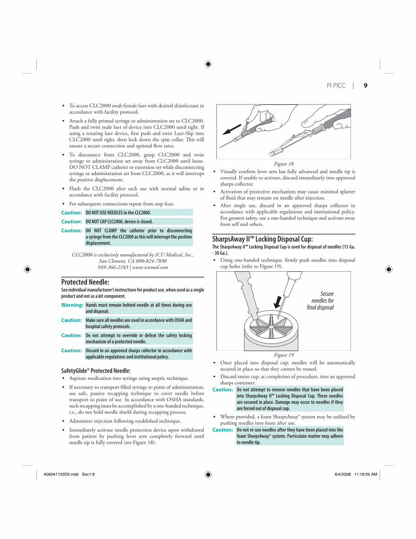
Immediately activate needle protection device upon withdrawal from patient by pushing lever arm completely forward until needle tip is fully covered (see Figure 18).
•
•
•
•
•
•
•
•
•
Figure 18Visually confi rm lever arm has fully advanced and needle tip is covered. If unable to activate, discard immediately into approved sharps collector.Activation of protective mechanism may cause minimal splatter of fl uid that may remain on needle after injection.After single use, discard in an approved sharps collector in accordance with applicable regulations and institutional policy. For greatest safety, use a one-handed technique and activate away from self and others.
SharpsAway II™ Locking Disposal Cup:The SharpsAway II™ Locking Disposal Cup is used for disposal of needles (15 Ga. - 30 Ga.).
Using one-handed technique, fi rmly push needles into disposal cup holes (refer to Figure 19).
Secureneedles for
final disposal
Figure 19Once placed into disposal cup, needles will be automatically secured in place so that they cannot be reused. Discard entire cup, at completion of procedure, into an approved sharps container.
Caution: Do not attempt to remove needles that have been placed into SharpsAway II™ Locking Disposal Cup. These needles are secured in place. Damage may occur to needles if they are forced out of disposal cup.
Where provided, a foam SharpsAway® system may be utilized by pushing needles into foam after use.
Caution: Do not re-use needles after they have been placed into the foam SharpsAway® system. Particulate matter may adhere to needle tip.
•
•
•
•
•
•
•
A06041102D0.indd Sec1:9A06041102D0.indd Sec1:9 6/4/2008 11:19:25 AM6/4/2008 11:19:25 AM

10 |
Pre-PICC Insertion & Patient Assessment ActivitiesPerform hand hygiene as required.
A procedural checklist is included on back of product label.
Procedural Pause:
1. Verify physician order: Confi rm correct patient.Confi rm correct diagnosis.Confi rm correct procedure.
Physician order must include post placement assessment of catheter tip placement (x-ray exam or other method in compliance with hospital protocol).
2. Patient education: Explain procedure to patient. Make sure information is presented with respect to patient’s level of understanding, culture, and language.
3. Have informed consent signed, if required.
4. Identify insertion vein: Apply tourniquet above anticipated insertion vein. Identify appropriate vein for insertion. Use direct visualization technologies, if available, and assess vein health.
NOTE: PICCs are typically inserted into basilic, brachial, or cephalic veins (refer to Figure 20).
Basilic Vein
Brachial Vein
Cephalic Vein
Cephalic Vein
Figure 20
•
•
•
•
•
5. Release tourniquet and leave in place beneath the arm.
6. Measure patient to assure placement of catheter in the SVC:Extend arm laterally 45 to 90 degrees from trunk. Measure distance from insertion site along presumed anatomical course of vessel to be catheterized. Catheter tip should lie in distal one-third of SVC above right atrium and parallel to SVC wall.
If a catheter stabilization device will be used, add ½ to 1 inch (1.2 to 2.5 cm) to catheter measurement (STATLOCK®); if another device is used, check manufacturer recommendations.If using upper arm circumference assessment; for consistency in measurement, measure from an anatomical point and record.
7. Position patient as appropriate for insertion site: Extend arm laterally 45 to 90 degrees from trunk.
8. Prepare work area.
Preparing for PICC Insertion:Perform hand hygiene as required:
before and immediately after all clinical proceduresbefore and after donning and removal of gloves
Use universal blood and body-fl uid precautions in the care of all patients due to the risk of exposure to HIV (Human Immunodefi ciency Virus) or other blood borne pathogens.
Handle and dispose of sharps appropriately in accordance with state/federal OSHA standards for blood borne pathogens and/or institutional policy.
Clinicians should use sterile technique, maximal sterile barrier precautions throughout the procedure, and dress in protective clothing:
mask • eye protectionsterile gown • sterile gloveshair cover
Prep Puncture Site: 1. Prep and drape peripheral puncture site.
2. Perform skin wheal with a local anesthetic as needed.
3. In kits where provided, the SharpsAway II™ Locking Disposal Cup is used for disposal of needles (15 Ga. - 30 Ga.).
Caution: Do not attempt to remove needles that have been placed into SharpsAway II™ Locking Disposal Cup. These needles are secured in place. Damage may occur to needles if they are forced out of disposal cup.
Prepare All Equipment: Prepare Catheter with Placement Wire for Insertion (where provided)(refer to Figure 21).
•
•
•
◊
◊
•
••
•
•
•
•
•
•
•
A06041102D0.indd Sec1:10A06041102D0.indd Sec1:10 6/4/2008 11:19:25 AM6/4/2008 11:19:25 AM

PI PICC | 11
Figure 21
Remove catheter tip protector.
Trim Catheter:If necessary, review detailed instructions for Catheter Trimmer device under Accessory Component Instructions section.1. Identify catheter type:
BFT (Blue FlexTip®)Non-BFT
2. Peel back contamination guard exposing catheter portion to be trimmed.
3. Review catheter marking pattern below. Th e catheter is marked so clinician can easily identify desired amount of catheter to be trimmed; length of catheter that remains or as with BFT catheter – both.
BFT double numbering pattern:
BFT Hub
5/50 50/550l55l50
Figure 22First number designates centimeters from tip of catheter.Second number designates centimeters from hub of catheter.Th is double numbering pattern permits clinician to easily identify centimeters of catheter to be trimmed and also identifi es centimeters of catheter remaining.Record both numbers.
Non-BFT numbering pattern:
Tip Hub
50 5550
Figure 23Number designates centimeters of catheter to be trimmed and also gives amount of catheter remaining.
•
•
•
•
◊
◊
◊
◊
•
◊
4. Using the trimming device, cut catheter straight across (90° to catheter cross-section) to maintain a blunt tip. NOTE: There should be very limited resistance when cutting catheter with supplied trimming device. If using a catheter with a placement wire, any greater resistance is likely to be caused by the placement wire which has not been suffi ciently retracted. If so, do not use catheter.
5. Inspect cut surface for clean cut and no loose material. Warning: Do not cut placement wire when trimming catheter to
minimize the risk of foreign embolism.
Caution: Check that there is no wire in cut catheter segment, after trimming catheter. If there is any evidence that placement wire has been cut or damaged, catheter should not be used.
Flush Catheter:1. Use fi lter straw to withdraw solution from glass ampules. 2. Attach syringe to sidearm and fl ush distal lumen with sterile
saline solution. Leave syringe in place. 3. Flush remaining lumen(s) with sterile saline. Clamp or attach
injection site cap(s) to extension line(s) to contain saline within lumen.
Catheter Insertion Instructions1. Reapply tourniquet and replace sterile gloves.2. Locate vein for insertion:
Use image guidance, if available. An echogenic needle is included for access.3. Insert introducer needle into vein. Check for pulsatile fl ow. Pulsatile fl ow is usually an indicator of
inadvertent arterial puncture.Caution: The color of blood observed is not always a reliable indicator
of venous access.
Gain Initial Venous Access:See specifi c guidewire instructions, Guidewire Insertion Techniques (page 7) under Accessory Component Instructions section.
1. Insert soft tip of guidewire through introducer needle into vein. Advance guidewire to desired depth.
Warning: Do not insert stiff end of soft tip guidewire into vessel as this may result in vessel damage.
Warning: Do not cut guidewire to alter length. Warning: Do not withdraw guidewire against needle bevel to minimize
the risk of possible severing or damaging of guidewire.
2. Remove needle: Hold guidewire in place while removing introducer needle. Caution: Maintain fi rm grip on guidewire at all times.
3. Enlarge puncture site, if necessary: Use scalpel positioned away from the guidewire to enlarge
cutaneous puncture site. Do not cut guidewire. Retract scalpel to the protected position.
•
A06041102D0.indd Sec1:11A06041102D0.indd Sec1:11 6/4/2008 11:19:26 AM6/4/2008 11:19:26 AM

12 |
Sheath Placement:1. Th read tapered tip of peel-away sheath/dilator assembly over
guidewire. Grasping near skin advance assembly with slight twisting motion to a depth suffi cient to enter vessel. Dilator may be partially withdrawn to further facilitate advancement of sheath into the vessel. A slight twisting motion of the peel-away might help sheath advancement.
Caution: Do not withdraw tissue dilator until the sheath is well within the vessel to minimize the risk of damage to sheath tip. Suffi cient guidewire length must remain exposed at hub end of sheath to maintain a fi rm grip on guidewire.
2. Check sheath placement by holding sheath in place, withdraw guidewire and dilator suffi ciently to allow venous blood fl ow. Holding sheath in place, remove guidewire and dilator as a unit.
Warning: Do not leave the dilator in place as an indwelling catheter to minimize the risk of possible vessel wall perforation.
Warning: Do not apply undue force on guidewire to minimize the risk of possible breakage.
Catheter Advancement: Advance catheter according to the guidewire used. Review detailed instructions for 80 cm and 130 cm guidewire usage (page 7) under Accessory Component Instructions section.Warning: Do not apply excessive force in placing or removing
catheter. Failure to do so can result in catheter breakage. If placement or withdrawal cannot be easily accomplished, an x-ray should be obtained and further consultation requested.
1. Retract catheter guard.2. Insert catheter through peel-away sheath.
If resistance is met while advancing catheter, retract and/or gently fl ush while advancing.
3. Stop advancing catheter 5 inches (13 cm) before reaching pre-established insertion length.
4. Withdraw peel-away sheath over catheter until free from venipuncture site.
5. Grasp tabs of peel-away sheath and pull apart, away from catheter, until sheath splits down entire length.
6. Advance catheter to fi nal indwelling position.
Placement Wire (where provided):Caution: To minimize the risk of placement wire kinking, do not
clamp extension line(s) when placement wire is in catheter.
1. Complete catheter insertion.2. Remove placement wire.
Warning: Remove placement wire and Luer-Lock sidearm assembly as a unit (see Figure 24). Failure to do so may result in wire breakage.
•
Figure 24
Caution: Catheter clamp and fastener (if provided and used) must not be attached to catheter until either guidewire or placement wire is removed.
Verify Catheter Tip Placement:1. Examine tip of placement wire after removal to ensure wire has
not been altered (see Figure 25).
Figure 25
2. If there is any indication placement wire is damaged, catheter and placement wire should be removed together.
3. Check catheter placement with syringe by aspirating through distal lumen until free fl ow of venous blood is observed.
Caution: The color of blood is not always a reliable indicator of venous access.
Complete Catheter Insertion:1. Flush lumen(s) to completely clear blood from catheter.
2. Connect extension line(s) to appropriate Luer-Lock line. Alternately, port(s) may be “locked” through injection cap(s) using standard hospital/agency protocol. Slide clamp(s) is provided on extension line to occlude fl ow through lumen during line and injection cap changes.
Warning: Slide clamp(s), where provided, may be inadvertently removed and aspirated by children or confused adults. In such situations, practitioners should remove slide clamp(s) when not in use.
A06041102D0.indd Sec1:12A06041102D0.indd Sec1:12 6/4/2008 11:19:26 AM6/4/2008 11:19:26 AM

PI PICC | 13
3. Cleanse insertion site per hospital/agency protocol.Caution: Do not routinely apply prophylactic topical antimicrobial
or antiseptic ointment or cream to the insertion site of peripheral venous catheters because of the potential risk to promote fungal infections and antimicrobial resistance.
4. Ensure insertion site is dry before applying dressing. Apply skin protectant as needed.
5. Secure catheter. Where provided, a catheter clamp, fastener, catheter stabilization device or Steri-Strip® may be used.
6. Assess placement of catheter tip in compliance with hospital protocol.
Documentation Institutions must establish a permanent medical record that
documents the entire procedure, based upon their policy,
procedures, and Best Practices. The actual format can diff er
from institution to institution. Report any product defects/
failures to organization risk management, manufacturers,
and appropriate regulatory agencies.
Documentation generally includes (but is not limited to) the following information:1. Device specifi cs:
type, brand and lot numberlength and size of Vascular Access Device (VAD)internal/external catheter lengthwhether catheter is trimmed
2. Procedure specifi cs:time out or procedural pauseinformed consent, as requireddate, time of insertion, insertion site, number and site attempts, inserter’s identifi cationuse of visualization and guidance technologiessite preparation and technique
3. Patient assessment and response:pertinent dx, assessment, vital signsunderstanding of procedure, patient’s response to procedurecomplications and barriers to care
4. Th erapy specifi cs:type of therapy, drug dose, rate, timeroute and method of administrationlaboratory specimen collected
5. Visual confi rmation: verifi cation of appropriate tip location prior to initial use
6. Monitor patient for post catheter insertion complications.
•
•
•
•
•
•
•
•
•
•
•
•
•
•
•
•
Care and Maintenance
Dressing:Replace dressing according to organizational policies, procedures, and practice guidelines. Change immediately if the integrity becomes compromised e.g. dressing becomes damp, soiled, loosened, or no longer occlusive.
Consult manufacturer’s recommendations for dressing specifi cs.
Transparent semipermeable membrane dressing should be changed every 7 days.
Gauze and tape should be changed every 48 hours.
Label dressing with type, size, and length of catheter; date and time; and initials of the clinician performing dressing change.
Maintain Catheter Patency:Maintaining central venous catheter patency shall be done in accordance with organizational policies, procedures, and practice guidelines. All personnel who care for patients with central venous catheters must be knowledgeable about eff ective management to prolong catheter’s dwell time and prevent injury.
Perform hand hygiene as required.
1. Solution and frequency of fl ushing a venous access catheter should be established in hospital/agency policy.
2. Catheter patency is established and maintained by:fl ushing intermittently via syringe with heparinized saline or preservative-free 0.9% sodium chloride (USP)continuous drippositive pressure device
3. Th e amount of heparin:depends on physician preference,hospital/agency protocol,patient condition
Caution: Assess patient for heparin sensitivity. Heparin-induced thrombocytopenia (HIT) has been reported with the use of heparin fl ush solutions.
4. Th e volume of fl ush solution should be:equal to at least twice the priming volume of the catheter and any add-on devices
Catheter priming volume is printed on product packaging.
5. When using any central venous catheter for intermittent infusion therapy, proper fl ushing (heparinization) using a positive-pressure fl ushing technique will help prevent occlusion. Neutral as well as positive displacement valve systems have also been shown to help prevent occlusion.
6. All valves need to be properly cleansed with an appropriate antiseptic before being accessed.
7. Th e SASH or SAS method of fl ushing will help eliminate occlusions due to incompatible solutions:
• Saline • Administer drug • Saline • Heparin (if used)
•
•
•
•
•
•
•
•
•
•
•
A06041102D0.indd Sec1:13A06041102D0.indd Sec1:13 6/4/2008 11:19:26 AM6/4/2008 11:19:26 AM

14 |
Catheter Removal Procedure1. PICC removal shall be performed:
following order of authorized prescriber in accordance with organizational policies, procedures, and practice guidelines
2. A PICC shall be removed immediately upon patient assessment for:
suspected contaminationunresolved complicationdiscontinuation of therapy
3. As indicated, place patient in supine position to minimize the risk of potential air embolism.
4. Remove dressing. Warning: Do not use scissors to remove dressing, to minimize the risk
of cutting catheter.
5. Open catheter stabilization device retainer wings and remove catheter from catheter stabilization device posts.
6. Remove catheter by slowly pulling it parallel to skin. If resistance is met when removing the catheter, catheter should not be forcibly removed and the physician should be notifi ed.
Caution: Do not exert excessive force while removing the catheter; to minimize the risk of catheter breakage.
•
•
•
•
•
7. Upon removal of catheter:measure and inspect ensure entire catheter length has been removed
8. Direct pressure should be applied at site until hemostasis is achieved.
9. Apply alcohol swab to catheter stabilization device adhesive and gently lift pad off of skin (if applicable).
10. Dress insertion site. Sterile occlusive dressing should be applied and site assessed every 24 hours until site is epithelialized. Residual catheter track may remain an air entry point until completely sealed (usually 24 to 72 hrs); dependent upon amount of time catheter was indwelling.
11. Document catheter removal procedure on patient’s chart per hospital/agency protocol.
Include:catheter conditionlength of catheter removedpatient’s tolerance of the procedureany nursing interventions needed for removal
For reference literature concerning patient assessment,
clinician education, insertion techniques and potential
complications associated with central venous access refer to
Arrow International, Inc. website: www.arrowintl.com
•
•
•
•
•
•
A06041102D0.indd Sec1:14A06041102D0.indd Sec1:14 6/4/2008 11:19:26 AM6/4/2008 11:19:26 AM

PI PICC | 15
A06041102D0.indd Sec1:15A06041102D0.indd Sec1:15 6/4/2008 11:19:27 AM6/4/2008 11:19:27 AM

2400 Bernville Road, Reading, PA 19605 USA | 1-800-523-8446 1-610-378-0131 | 8 a.m. - 8 p.m. EST | www.arrowintl.com
A-06041-102D (6/08)
A06041102D0.indd Sec1:16A06041102D0.indd Sec1:16 6/4/2008 11:19:27 AM6/4/2008 11:19:27 AM