Embed Size (px)
Citation preview

Chemical Engineering Journal 417 (2021) 128080
A1
PaFa
b
c
A
KSHPPS
1
fhpTTgwptmit
id
hR
Contents lists available at ScienceDirect
Chemical Engineering Journal
journal homepage: www.elsevier.com/locate/cej
ressure drop and heat transfer of ZoneFlowTM structured catalytic reactorsnd reference pellets for Steam Methane Reforminglorent Minette a,b, Luis Calamote de Almeida a,b,c, Sanjiv Ratan c, Juray De Wilde a,b,∗
Université Catholique de Louvain, Materials & Process Engineering ( imap), Place Sainte Barbe 2, B-1348 Louvain-la-Neuve, BelgiumUCLouvain, Research and Innovation Centre for Process Engineering (ReCIPE), Place Sainte Barbe 2, B-1348 Louvain-la-Neuve, BelgiumZoneFlow Reactor Technologies, LLC, 41 Mechanic Street, P.O. Box 278, Windsor, CT 06095, USA
R T I C L E I N F O
eywords:tructured catalytic reactorseat transferressure droprocess intensificationteam Methane Reforming
A B S T R A C T
Structured catalytic reactors have the potential to combine reduced pressure drop and improved heat transfercompared to conventional pellets. In the present study, the pressure drop and heat transfer coefficient betweenthe tube wall and the process gas were measured experimentally for annular structured ZoneFlowTM reactorsof different design and for two commercial reference pellets. The ZoneFlowTM reactors differ by the design ofthe central rod that supports the near-wall annular casing. The experiments were carried out in a 1 m longreactor, at atmospheric pressure and with air flow rates from 70 to 330 Nm3/h. To measure the heat transfercoefficient, the furnace was set at a constant temperature that was varied in the range 100–500 ◦C and theaxial profiles of the tube wall and gas temperatures were measured. Using the experimental data, correlationsfor the friction factor and the Nusselt number were derived and the introduced parameters estimated usingnon-linear regression. A correlation for the static contribution to heat transfer for the structured reactors wasderived from 3D numerical simulations. The correlations were then used to evaluate the pressure drop–heattransfer advantage of the structured reactors compared to the reference pellets at typical industrial steammethane reforming conditions. The data show that ZoneFlowTM reactors can provide a roughly doubled heattransfer coefficient at comparable pressure drop than the tested reference pellets. Furthermore, modificationof the central rod support structure was found an efficient way to balance the pressure drop–heat transferadvantage of ZoneFlowTM reactors using an identical design casing.
. Introduction
Steam reforming of natural gas is the most widely practiced processor the large-scale production of hydrogen and syngas, a mixture ofydrogen and carbon monoxide. Downstream applications include theroduction of ammonia, methanol, synthetic fuels via the Fischer–ropsch synthesis and hydrotreatment processes, among others [1,2].he conversion of natural gas to higher value products has recentlyained interest, driven by the increased availability of natural gas,ith impactful effects in terms of supply and price [3–8]. The ex-anding fertilizer market and related ammonia production is expectedo increase hydrogen demand, as well as the increasing interest inethanol as flexible and transport efficient chemical intermediate. An
ncrease in capacity and efficiency of steam methane reformers faceshe limitations of the currently used reactor technology.
The reforming reactions are strongly endothermic and carried outn a multi-tubular fixed bed reactor, with hundreds of relatively smalliameter tubes suspended in a furnace [9]. The throughput is limited
∗ Corresponding author at: Université Catholique de Louvain, Materials & Process Engineering (imap), Place Sainte Barbe 2, B-1348 Louvain-la-Neuve, Belgium.
by poor heat transfer between the tube inner wall and the process gas.Sufficient heat needs to be supplied without exceeding the maximumtube skin temperature. Around 50% of the total heat input to thereformer is effectively transferred to the process gas [10]. To preventradial temperature differences and poor use of the catalyst in thecenter of a reformer tube, 10 cm diameter tubes are used [11–13]. Todeal with as well constraints on pressure drop, interfacial transfer andintra-particle diffusion, complexly shaped and perforated pellets areused with an equivalent diameter of roughly 5–10 mm. Nevertheless,catalyst effectiveness factors lower than 5% are typically reported [14].Pellets size and design can be optimized [15,16], but whatever theirshape, there is a relatively well defined relation between heat transferperformance and pressure drop.
Structured catalytic reactors have been developed to deal with thelimitations mentioned above and are of particular interest for highlyexo- and endothermic reactions. An engineered packing is designed tooptimize the flow pattern, in order to combine improved heat transfer
vailable online 13 December 2020385-8947/© 2020 Elsevier B.V. All rights reserved.
E-mail address: [email protected] (J. De Wilde).
ttps://doi.org/10.1016/j.cej.2020.128080eceived 5 October 2020; Received in revised form 30 November 2020; Accepted 5
December 2020
Chemical Engineering Journal 417 (2021) 128080F. Minette et al.
otbppoAdt(afsrialtslr
sgfspdwgrnTonttahos
Nomenclature
Cross-sectional area (m2)𝐴 Heat exchanging surface (m2)𝑎𝑣 Casing surface area per volume reactor
(m2/m3r)
𝐶𝐴 Species molar concentration (molA/m3g)
𝑐𝑝 Heat capacity at constant pressure (J/kg K)𝑑𝑐𝑎𝑡 Catalyst coating thickness (m)𝑒𝐴 Effective diffusivity of species A in the
catalyst coating (m3g/mcat.s)
𝑑ℎ ZoneFlowtm hydraulic diameter (m)𝑑𝑝 Pellet diameter (m)𝑑𝑡 Tube diameter (m)𝑓 Friction factor𝐺 Gas mass flux (kgg/m2
r.s)ℎ ZoneFlowtm casing material thickness (m)𝛥𝐻 Heat of reaction (kJ/mol)ℎ𝑓 Heat transfer coefficient from gas to solid
interface (J/m2i K s)
𝑘𝑔 Mass transfer coefficient from gas to solidinterface (m3
g/m2i.s)
𝐿 ZoneFlowtm casing channel height (m)𝑁𝑢 Nusselt number𝑝 Total pressure (bar)𝑃𝑟 Prandtl number𝑞 Heat flux (W/m2)𝑟𝑐 ZoneFlowtm reactor annulus width (m)𝑟𝑗 Rate of reaction 𝑗 (mol/kgcat.s)𝑅𝑒 Reynolds number𝑇 Temperature (K)𝑢𝑠 Gas superficial velocity (m3
g/m2r.s)
𝑤 ZoneFlowtm casing channel width (m)𝑧z Axial coordinate in the reactor (m)
Greek letters
𝛼𝐴,𝑗 Stoechiometric coefficient of species A inreaction j
𝛼𝑖 Convective heat transfer coefficient, bedside (W/m2 K)
𝛼0 Static contribution to heat transfer (W/m2
K)𝜀 Reactor void fraction (m3
g/m3r)
𝜂𝑗 Effectiveness factor of reaction j𝜆 Thermal conductivity (W/m K)𝜆0er Effective thermal conductivity in the radial
direction (W/m K)𝜇 Gas viscosity (Pa s)𝜉 Non-dimensional intra-catalyst coordinate𝜌𝑠 Catalyst density (kgcat/m3
cat)
and reduced pressure drop compared to pellets. The use of a thincatalyst coating on the reactor internals ensures improved catalysteffectiveness. 3D printing technology has opened perspectives to newgeometries, difficult to manufacture otherwise, but is still relativelyexpensive. Cost and ease of installation and replacement are importantfactors to account for when developing a structured reactor solution.Pangarkar et al. (2009) experimentally studied various structured pack-ings, including open-cell foams, open cross flow (OCFS) and close crossflow (CCFS) structures, for the Fischer–Tropsch synthesis [17]. The
2
a
Subscripts
𝑑ℎ ZoneFlowtm hydraulic diameter based𝑑𝑝 Particle diameter based𝑔 Gas phaseP Reference pellets𝑠 Solid phase𝑡 Tube𝑤 Tube wallZF ZoneFlowtm reactor
combination of experimental measurements and fundamental modelingdemonstrated better radial heat transport properties for these variousstructures compared to randomly packed beds, e.g. opening the wayto operation with larger reactor diameters. Fratalocchi et al. (2018)carried out Fischer–Tropsch synthesis tests using an aluminum foamloaded with active Co/Pt/Al2O3 catalyst spheres of 300 μm diame-ter, under commercially representative operating conditions [18]. Theconcept of a packed foam was introduced to overcome the catalyst in-ventory issue [19,20]. A comparison was made with a randomly packedbed of identical catalyst spheres diluted with inert 𝛼-Al2O3 particlesf identical size. The packed foam was shown to be stable duringemperature ramping while runaway was observed with the packeded of spheres, demonstrating highly improved radial heat transportroperties by the presence of the metallic foam. Sanz et al. (2016)erformed methanol steam reforming experiments on several typesf metal monoliths of various cell density and catalyst content [21].ccurate radial temperature profile measurements showed steeper gra-ients with decreasing cell density, resulting from a lower effectivehermal conductivity of the structure. Computational Fluid DynamicsCFD) simulations confirmed this observation. Specific structures suchs the ZoneFlowtm and the CatacelTM reactors have been designedor steam methane reforming and tested at the pilot and commercialcales. The latter uses stacked fans made of triangular ducts, guidingadially the gas toward and away from the tube wall [22,23]. The gasmpinging the heated wall allows improving heat transfer performancend pressure drop is reduced by 10%–20% compared to pellets. Theong-term performance of the CatacelTM reactor was evaluated underypical commercial steam reforming operating conditions [24] and thetructure was demonstrated to increase the tube lifetime, allowingower maximum tube skin temperature than with pellets, for a giveneactor operating temperature.
The present study focuses on the annular ZoneFlowtm reactor [25],hown in Fig. 1. The annular casing is made of sectors with bladesuiding the flow either towards or away from the tube wall. Radialins separate partially the sectors, except in the near-wall region wheremall openings allow flow in between adjacent sectors. The flow im-inging the tube wall is accompanied by a local increase of turbulenceue to rapid changes in velocity magnitude and direction in the near-all region. This results in improved heat transfer between the processas and the tube wall. De Wilde and Froment (2012) evaluated theesulting performance in SMR by means of Computational Fluid Dy-amics (CFD) simulations on a 1 meter long ZoneFlowtm reactor [26].he reactor comprised the annular casing and a central core composedf stacked, perforated and corrugated cones. Using detailed intrinsic ki-etics [27], they showed that higher methane conversion or throughputhan with a conventional packed bed could be achieved, taking advan-age of intensified heat transfer and high catalyst effectiveness factors,nd despite the lower catalyst inventory. They also showed improvedeat transfer reduces risk of coke formation, opening perspectives forperation at lower steam-to-carbon ratio. In follow-up CFD work, it washown that most of the flow and conversion took place in the near-wallnnulus, allowing simplification of the central core design [28]. As will

Chemical Engineering Journal 417 (2021) 128080F. Minette et al.
Fig. 1. The near-wall annular ZoneFlowtm casing structure. (a) A single casing element consisting of six rows of blades and (b) five stacked casing elements.
be discussed in more detail later, the central core evolved to essentiallya blocked tube equipped with collars or disks on which the annularcasing is suspended. This suspension system is essential as it ensuresclose contact between the casing and the tube wall, the casing beingpushed outward by its weight and the action of the flow. AdditionalCFD simulations were performed by De Wilde (2014) to study the effectof various design aspects of the casing, such as the blade angle of attackand the annulus width [29]. The annular ZoneFlowtm reactor can alsobe easily used with an open central tube (bayonet configuration) toallow counter-current heat recovery from the produced syngas that isdirectly used for the reforming, and reduce the excess steam produceddownstream of the reformer - an aspect not studied further here.
In the present paper, the pressure drop and the heat transfer be-tween the inner tube wall and the process gas are experimentallymeasured in a wide range of air flow rates, for various ZoneFlowtm
reactors and for standard and low-pressure drop reference pellets.The influence of the annulus width and of the design of the casing-supporting central rod are studied and correlations for the frictionfactor and the Nusselt number are derived. Finally, using the de-rived correlations, a comparison of the heat transfer–pressure dropperformance of the different reactors under typical commercial SMRconditions is made.
2. Experimental set-up
2.1. The ZoneFlowTM reactors and reference pellets
The annular ZoneFlowtm casing is shown in Fig. 1(a). A casingelement consists of 6 rows of blades and is 10 cm in length [25]. Theannular casing is 11.5 mm wide (radially) and divided in 50 sectors(tangentially). The blades in the sectors make a 45◦ angle with the cen-tral axis and form channels that guide the flow either towards or awayfrom the wall. Radial fins separate partially the sectors except in thenear-wall region where flow between sectors is allowed through smallopenings. The channel height, 𝐿, the axial distance between two blades,is 17 mm. The average channel width, 𝑤, is the length of the circular arcbetween two adjacent radial fins midway (5.75 mm) from the wall andis 5.9 mm. The average hydraulic diameter of a ZoneFlowtm channel,or characteristic channel size, is then 𝑑ℎ = 4×(𝐿×𝑤)∕(2×(𝐿+𝑤)) = 8.8mm. The casing is made of 100 μm thick stainless steel foil that is coated
3
with catalyst. A 1 m long reactor containing 10 stacked casing elementsis used. Fig. 1(b) shows 5 stacked casing elements mounted on thecentral rod prior to insertion in the tube. The reactor tube internaldiameter is 10 cm, typical for conventional SMR. By the action ofthe flow, gravity and interaction with the collars or disks mounted onthe central rod, the casing is pushed outward, ensuring good contactbetween the blades and the tube wall. Various designs of the centralrod are considered in this study, as illustrated in Fig. 2. The ZF12-2C, ZF12-2D and ZF12-6D use a 7.6 cm diameter central rod, withcorresponding annulus width 𝑟𝑐 of 12 mm. The ZF12-2C design usestwo conical collars per casing element (Fig. 2(a-b)). The ZF12-2D andZF12-6D use respectively two and six disks per casing element (Fig. 2(c-f)). The collars and disks have an 86 mm external diameter. Comparedto collars, disks are easier and less costly to manufacture. For theZF12-2C and ZF12-2D designs, a gap in the near-central rod regionexists in rows without collar or disk, allowing a certain gas by-pass.A lower pressure drop and, correspondingly, heat transfer coefficientis expected for such designs. The ZF14-2D86 and ZF14-2D84 designsuse a 7.2 cm diameter central rod, providing a 14 mm annulus width.By adapting the outer diameter of the disks, an identical casing canbe used in the 12 and 14 mm ZoneFlowtm reactors. Increasing theannulus width allows reducing the gas superficial velocity for a givenflow rate, leading to reduced pressure drop. All ZF14 designs use twodisks per casing element (Fig. 2(c-d)), but the disk size was varied withrespectively an 86 and 84 mm external diameter. All the dimensionsand design parameters are summarized in Table 1.
Identical pressure drop and heat transfer testing is carried out usingstandard and low-pressure drop reference pellets. The standard pelletsare quadralobe with 4 holes and a 5.9 mm equivalent diameter, definedas the diameter of the sphere with the same surface area per unitvolume. The low-pressure drop reference pellets are cylinders with 7holes and an 8.6 mm equivalent diameter. The pellets dimensions,densities and measured bed void fractions are summarized in Table 2.
2.2. Operating conditions and instrumentation
The pressure drop and heat transfer coefficient between the tubewall and the process gas are experimentally measured in the setupshown in Fig. 3(a). A schematic representation is given in Fig. 3(b). Air
3
is fed at different flow rates between 60 and 330 Nm /h, covering mass
Chemical Engineering Journal 417 (2021) 128080F. Minette et al.
Fig. 2. Schematic representation and picture of the ZoneFlowtm structure with a central rod comprising (a)–(b) 2 conical collars per casing elements (ZFxx-2C), (c)–(d) 2 disks percasing element (ZFxx-2D) and (e)–(f) 6 disks per casing element (ZFxx-6D).
Table 1The various ZoneFlowtm reactors considered in this study.
ZF12-2C ZF12-2D ZF12-6D ZF14-2D86 ZF14-2D84
Annulus width, 𝑟𝑐 (mm) 12 12 12 14 14Central rod diameter (mm) 76 76 76 72 72Central rod configuration (per casing element) 2 collars 2 disks 6 disks 2 disks 2 disksDisk/collar diameter (mm) 86 86 86 86 84Casing specific surface area 𝑎𝑣 (𝑚2∕𝑚3
𝑟 ) 397 397 397 340 340Void fraction, 𝜀 (𝑚3
𝑔∕𝑚3𝑟 ) 0.98015 0.98015 0.98015 0.983 0.983
4
Chemical Engineering Journal 417 (2021) 128080F. Minette et al.
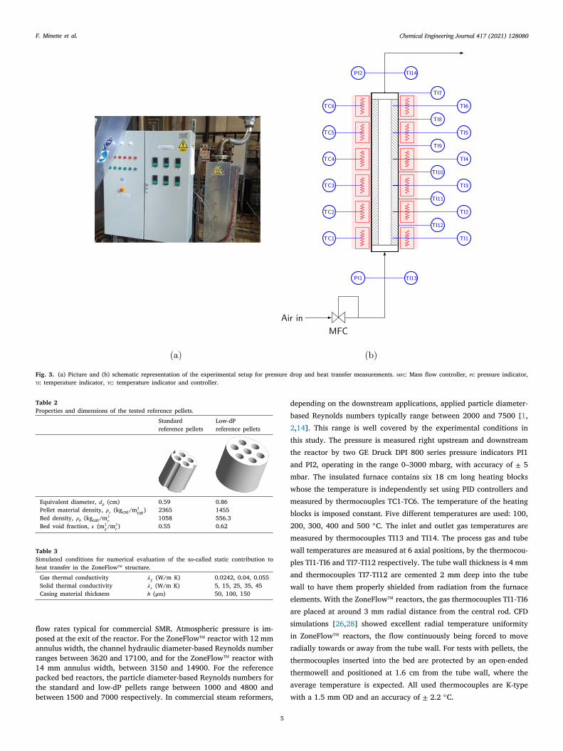
Fig. 3. (a) Picture and (b) schematic representation of the experimental setup for pressure drop and heat transfer measurements. mfc: Mass flow controller, pi: pressure indicator,ti: temperature indicator, tc: temperature indicator and controller.
Table 2Properties and dimensions of the tested reference pellets.
Standard Low-dPreference pellets reference pellets
Equivalent diameter, 𝑑𝑝 (cm) 0.59 0.86Pellet material density, 𝜌𝑠 (kgcat/m3
cat) 2365 1455Bed density, 𝜌𝑏 (kgcat/m3
𝑟 1058 556.3Bed void fraction, 𝜀 (m3
𝑔/m3𝑟 ) 0.55 0.62
Table 3Simulated conditions for numerical evaluation of the so-called static contribution toheat transfer in the ZoneFlowtm structure.
Gas thermal conductivity 𝜆𝑔 (W/m K) 0.0242, 0.04, 0.055Solid thermal conductivity 𝜆𝑠 (W/m K) 5, 15, 25, 35, 45Casing material thickness ℎ (μm) 50, 100, 150
flow rates typical for commercial SMR. Atmospheric pressure is im-posed at the exit of the reactor. For the ZoneFlowtm reactor with 12 mmannulus width, the channel hydraulic diameter-based Reynolds numberranges between 3620 and 17100, and for the ZoneFlowtm reactor with14 mm annulus width, between 3150 and 14900. For the referencepacked bed reactors, the particle diameter-based Reynolds numbers forthe standard and low-dP pellets range between 1000 and 4800 andbetween 1500 and 7000 respectively. In commercial steam reformers,
5
depending on the downstream applications, applied particle diameter-based Reynolds numbers typically range between 2000 and 7500 [1,2,14]. This range is well covered by the experimental conditions inthis study. The pressure is measured right upstream and downstreamthe reactor by two GE Druck DPI 800 series pressure indicators PI1and PI2, operating in the range 0–3000 mbarg, with accuracy of ± 5mbar. The insulated furnace contains six 18 cm long heating blockswhose the temperature is independently set using PID controllers andmeasured by thermocouples TC1-TC6. The temperature of the heatingblocks is imposed constant. Five different temperatures are used: 100,200, 300, 400 and 500 ◦C. The inlet and outlet gas temperatures aremeasured by thermocouples TI13 and TI14. The process gas and tubewall temperatures are measured at 6 axial positions, by the thermocou-ples TI1-TI6 and TI7-TI12 respectively. The tube wall thickness is 4 mmand thermocouples TI7-TI12 are cemented 2 mm deep into the tubewall to have them properly shielded from radiation from the furnaceelements. With the ZoneFlowtm reactors, the gas thermocouples TI1-TI6are placed at around 3 mm radial distance from the central rod. CFDsimulations [26,28] showed excellent radial temperature uniformityin ZoneFlowtm reactors, the flow continuously being forced to moveradially towards or away from the tube wall. For tests with pellets, thethermocouples inserted into the bed are protected by an open-endedthermowell and positioned at 1.6 cm from the tube wall, where theaverage temperature is expected. All used thermocouples are K-typewith a 1.5 mm OD and an accuracy of ± 2.2 ◦C.

Chemical Engineering Journal 417 (2021) 128080F. Minette et al.
r
m
wedsiTr
H
Table 4Correlations for the friction factors and the Nusselt numbers for the two reference pellets and the 5 tested ZoneFlowtm configurations.
Friction factor for pressure drop Nusselt number for heat transfer
Reference pelletsStandard pellets 𝑓 = 10.5 (1−𝜀)1.2
𝜀3𝑅𝑒−0.3𝑑𝑝
𝑅2𝑎𝑑𝑗 = 0.967 𝑁𝑢𝑑𝑝 =
𝛼0𝑃 𝑑𝑝𝜆𝑔
+ 0.25𝑅𝑒0.72𝑑𝑝𝑃𝑟1∕3 𝑅2
𝑎𝑑𝑗 = 0.963
Low-dP pellets 𝑓 = 4.63 (1−𝜀)1.2
𝜀3𝑅𝑒−0.16𝑑𝑝
𝑅2𝑎𝑑𝑗 = 0.985 𝑁𝑢𝑑𝑝 =
𝛼0𝑃 𝑑𝑝𝜆𝑔
+ 0.15𝑅𝑒0.76𝑑𝑝𝑃𝑟1∕3 𝑅2
𝑎𝑑𝑗 = 0.968
ZoneFlow𝑇𝑀 structure
ZF12-2C 𝑓 = 16𝑅𝑒𝑑ℎ
+ 0.272𝑅𝑒−0.05𝑑ℎ𝑅2
𝑎𝑑𝑗 = 0.988 𝑁𝑢𝑑ℎ = 𝛼0𝑍𝐹 𝑑ℎ𝜆𝑔
+ 8.34𝑅𝑒0.36𝑑ℎ𝑃𝑟1∕3 𝑅2
𝑎𝑑𝑗 = 0.979
ZF12-2D 𝑓 = 16𝑅𝑒𝑑ℎ
+ 0.331𝑅𝑒−0.06𝑑ℎ𝑅2
𝑎𝑑𝑗 = 0.989 𝑁𝑢𝑑ℎ =𝛼0ZF𝑑ℎ
𝜆𝑔+ 4.27𝑅𝑒0.43𝑑ℎ
𝑃𝑟1∕3 𝑅2𝑎𝑑𝑗 = 0.979
ZF12-6D 𝑓 = 16𝑅𝑒𝑑ℎ
+ 0.569𝑅𝑒−0.06𝑑ℎ𝑅2
𝑎𝑑𝑗 = 0.989 𝑁𝑢𝑑ℎ =𝛼0ZF𝑑ℎ
𝜆𝑔+ 4.85𝑅𝑒0.43𝑑ℎ
𝑃𝑟1∕3 𝑅2𝑎𝑑𝑗 = 0.977
ZF14-2D86 𝑓 = 16𝑅𝑒𝑑ℎ
+ 0.468𝑅𝑒−0.07𝑑ℎ𝑅2
𝑎𝑑𝑗 = 0.995 𝑁𝑢𝑑ℎ =𝛼0ZF𝑑ℎ
𝜆𝑔+ 5.75𝑅𝑒0.41𝑑ℎ
𝑃𝑟1∕3 𝑅2𝑎𝑑𝑗 = 0.954
ZF14-2D84 𝑓 = 16𝑅𝑒𝑑ℎ
+ 0.401𝑅𝑒−0.07𝑑ℎ𝑅2
𝑎𝑑𝑗 = 0.98 𝑁𝑢𝑑ℎ =𝛼0ZF𝑑ℎ
𝜆𝑔+ 5.38𝑅𝑒0.41𝑑ℎ
𝑃𝑟1∕3 𝑅2𝑎𝑑𝑗 = 0.969
𝜀𝑅𝑅(ratavitdTr
S
mw
3
N
𝑁
Table 5Considered air and SMR mixture properties and operating conditions for evaluationand comparison of the heat transfer coefficient for the ZoneFlowtm reactors and theeference pellets (see Figs. 10 and 11).
Air Typical SMR mixtureFig. 10(a) Fig. 10(b)
T 300 ◦C T 700 ◦Cp 1 bar p 30 bar𝜇 3.0 × 10⁻⁵ Pa s 𝜇 3.0 × 10⁻⁵ Pa s𝑐𝑝 1027 J/kg K 𝑐𝑝 2450 J/kg K𝜆𝑔 0.044 W/m K 𝜆𝑔 0.0735 W/m KPr 0.7 Pr 1
Composition (mol.%) Composition (mol.%)O2 21 CH4 20N2 79 H2O 60
H2 10CO2 5CO 2.5N2 2.5
3. Modeling and parameter estimation
3.1. Pressure drop
The pressure drop in the ZoneFlowtm reactor can be calculated byeans of a Fanning-type equation:
𝑑𝑝𝑑𝑧
= −2𝑓𝜌𝑔𝑢2𝑠𝑑ℎ
(1)
Based on an analogy with a bundle of empty channels with hydraulicdiameter 𝑑ℎ, the friction factor, 𝑓 , is modeled by:
𝑓 = 16𝑅𝑒𝑑ℎ
+ 𝑎1𝑅𝑒−𝑎2𝑑ℎ
(2)
ith the first term the well-known friction factor for laminar flow inmpty tubes, but using the Reynolds number based on the hydrauliciameter of a single ZoneFlowtm channel, 𝑅𝑒𝑑ℎ = 𝐺𝑑ℎ∕𝜇, and theecond term of a similar functional form as reported for turbulent flown empty tubes with 5000 < Re < 200000 (𝑓 = 0.046𝑅𝑒−0.2𝐷 ) [30].he empirical parameters 𝑎1 and 𝑎2 in Eq. (2) are to be estimated byegression for each tested configuration.
For the pellets, the pressure drop can be calculated as:
𝑑𝑝𝑑𝑧
= −𝑓𝜌𝑔𝑢2𝑠𝑑𝑝
(3)
The friction factor 𝑓 is modeled using the relation introduced by Hicks(1970) [31]:
𝑓 = 𝑎3(1 − 𝜀)1.2
𝜀3𝑅𝑒−𝑎4𝑑𝑝
(4)
with the equivalent diameter-based Reynolds number 𝑅𝑒𝑑𝑝 = 𝐺𝑑𝑝∕𝜇.
6
icks (1970) [31] determined for randomly packed spherical particles
that 𝑎3 = 6.8 and 𝑎4 = -0.2, but the parameters 𝑎3 and 𝑎4 were re-estimated for the complexly shaped reference pellets that were tested.Note that the classical Ergun equation [32] is only valid when 𝑅𝑒𝑑𝑝∕(1−) < 500, whereas the Handley and Hegg’s equation is valid for 1000 <𝑒𝑑𝑝∕(1 − 𝜀) < 5000. The present study covers the range 2200 <𝑒𝑑𝑝∕(1 − 𝜀) < 18400. Hicks (1970) proposed Eq. (4) that fits Ergun’s
1952) [32] and Handley and Hegg’s (1968) [33] data, as well as theesults of Wentz and Thodos at very high Reynolds number [30,34]nd is therefore adopted here. The pressure drop Eqs. (1) and (3), forhe ZoneFlowtm and pellets reactors respectively, were integrated using
4th order Runge–Kutta method. The variations of air density andiscosity with pressure and temperature were accounted for using thedeal gas law and Sutherland’s relation. During the pressure drop tests,he measured temperature difference between the inlet and outlet airid not exceed 10 ◦C and a mean constant temperature was considered.he parameters 𝑎1-𝑎4 were estimated using non-linear least squaresegression. The objective function to be minimized is given by:
SQ =𝑛∑
𝑖=1
(
𝛥𝑃𝑖 − 𝛥𝑃 𝑖
)2 𝒂←←←←←←→ min (5)
where 𝛥𝑃𝑖 and 𝛥𝑃 𝑖 are the measured and predicted pressure dropeasured for the 𝑖th experiment. The software Athena Visual Studioas used for the parameter estimation.
.2. Heat transfer modeling
A standard correlation for the ZoneFlowtm hydraulic diameter basedusselt number is proposed for the ZoneFlowtm reactors:
𝑢𝑑ℎ =𝛼𝑖𝑑ℎ𝜆𝑔
=𝛼0ZF𝑑ℎ𝜆𝑔
+ 𝑏1𝑅𝑒𝑏2𝑑ℎ𝑃𝑟1∕3 (6)
with 𝑏1 and 𝑏2 empirical parameters to be estimated from experimentaldata for each tested configuration. 𝛼𝑖 is the heat transfer coefficientfor convective heat transfer between the tube wall and the processgas, as introduced in 1D reactor models [30]. Note that the use ofa 1D reactor model is particularly justified for ZoneFlowtm reactorswith the process gas forced to continuously flow towards and awayfrom the wall. This leads to excellent radial temperature uniformityas it was illustrated by CFD simulations [26,28]. A similar approachbased on 1D reactor modeling was adopted by Giani et al. (2005) toderive a correlation for the Nusselt number to describe the gas–solidheat transfer in open-celled metallic foams [35]. The calculation ofthe so-called static contribution in the ZoneFlowtm structure 𝛼0ZF isaddressed numerically, as explained below. Because of the very highvoid fraction of ZoneFlowtm reactors (> 0.98), a comparison with theheat transfer coefficient of empty tubes is worth making. In the classicalDittus–Boelter equation, 𝑏1 = 0.023 and 𝑏2 = 0.8, the so-called staticcontribution being negligible.

Chemical Engineering Journal 417 (2021) 128080F. Minette et al.
For the pellets, a similar correlation for the Nusselt number basedon the equivalent diameter is adopted:
𝑁𝑢𝑑𝑝 =𝛼𝑖𝑑𝑝𝜆𝑔
=𝛼0P𝑑𝑝𝜆𝑔
+ 𝑏3𝑅𝑒𝑏4𝑑𝑝𝑃𝑟1∕3 (7)
The so-called static contribution 𝛼0P is given by [36,37]:
𝛼0P =10.21𝜆0𝑒𝑟,𝑝
𝑑4∕3𝑡
(8)
The effective radial thermal conductivity 𝜆0𝑒𝑟,𝑝 is calculated using therelation introduced by Kunii and Smith (1960) [38]. Some authors alsoinvestigated heat transfer parameters in fixed bed reactors theoreticallyand using CFD simulations [39,40].
To estimate parameters 𝑏1-𝑏4, non-linear regression is performedbetween measured and calculated gas temperatures at different axialpositions. The objective function to be minimized is given by:
SSQ =𝑛∑
𝑖=1
6∑
𝑘=1𝑤𝑖𝑘
(
𝑇𝑔,𝑖𝑘 − 𝑇𝑔,𝑖𝑘)2 𝒃
←←←←←←→ min (9)
with 𝑇𝑔,𝑖𝑘 and 𝑇𝑔,𝑖𝑘 the measured and predicted temperatures for the 𝑖th
experiment at the axial position corresponding to the 𝑘th thermocouple(TI1-TI6). Weighted regression was applied with 𝑤𝑖𝑘 the weight givento a certain data point. The gas temperatures at a given axial positionis calculated by integrating the following continuity equation:
𝑢𝑠𝜌𝑔𝑐𝑝𝑑𝑇𝑔𝑑𝑧
= 𝐴𝑏
(
1𝛼𝑖
+ 𝑒𝜆𝑤
𝐴𝑏𝐴𝑚
)−1(
𝑇𝑤 − 𝑇𝑔)
(10)
where 𝑇𝑔 is the calculated axial profile of the process gas temperatureand 𝑇𝑤 is the measured axial profile of the tube wall temperature,imposed during the regression. Thermal conduction in the tube wallis accounted for, with 𝑒 the tube thickness and 𝜆𝑤 the thermal conduc-tivity of the tube material, i.e. stainless steel. Note that since the tubethermocouples TI7-TI12 are cemented 2 mm deep in the 4 mm thicktube wall, 𝑒 is taken to be 2 mm. 𝐴𝑏 is the heat exchanging surfacebetween the gas and the tube wall on the inner tube side. 𝐴𝑚 is the logmean of 𝐴𝑏 and 𝐴𝑡, with 𝐴𝑡 the heat exchanging surface at the radialposition of the wall thermocouples TI7-TI12. The contribution of radia-tive heat transfer between the tube wall and the reactor internals wasfound negligible in the range of temperatures experimentally tested andabsorption of radiation by air can be neglected. In certain experimentswith pellets, some thermocouples were displaced when loading the bedand were contacting the tube wall, which was confirmed by means ofadditional and repetitive experiments. Gas temperature measurementswere then falsified at these axial positions and the corresponding datawere given zero weight. The parameter estimation was performed usingthe software Athena Visual Studio.
The so-called static, or conductive, contribution was found to bevery small compared to the dynamic or convective contribution inthe window of flow rates tested. A statistically significant estimationof parameter 𝛼0ZF from experimental data is then not feasible, butimportant in order to be able to determine the parameters of thedynamic contribution with sufficient precision. This static contributionwas therefore estimated numerically using finite volume simulations.The steady-state Laplacian equation, Eq. (11), was solved in a virtuallyreconstructed ZoneFlowtm structure containing 3 rows of blades and 4sectors, as shown in Fig. 4:
∇(
𝜆0𝑒𝑟,𝑍𝐹∇𝑇)
= 0 (11)
A temperature difference 𝛥𝑇 of 25 K was imposed between the twoboundaries of the domain in the radial direction and adiabatic condi-tions were imposed at all other surfaces. The static effective radial ther-mal conductivity in the ZoneFlowtm structure 𝜆0𝑒𝑟,𝑍𝐹 is then evaluatedvia:
𝜆0 =𝑟𝑐 ∫ 𝑞 𝑑
(12)
7
𝑒𝑟,𝑍𝐹 𝛥𝑇
Fig. 4. Computational domain for the numerical evaluation of the so-called staticcontribution in the ZoneFlowtm structure and contour plot of temperature for 𝜆𝑔 =0.0242 W/m K, 𝜆𝑠 = 25 W/m K and a casing material thickness of 100 μm.
with 𝑞 the calculated heat flux, the cross-sectional area in the radialdirection and 𝑟𝑐 the width of the computational domain. The so-calledstatic contribution for the ZoneFlowtm structure to the heat transfercoefficient then follows from:
𝛼0ZF =𝜆0𝑒𝑟,𝑍𝐹
𝑟𝑐(13)
To derive a correlation for 𝛼0ZF as a function of the gas and casingproperties, the thermal conductivity of the gas and of the casing ma-terial were varied and simulations were repeated for different casingthickness. The simulated conditions are summarized in Table 3. Thefinite volume solver Fluent 18.1 (Ansys) was used with a second orderupwind discretization scheme for the Laplacian operator. Convergencewas supposed to be achieved for residuals below 10−16. The approachis similar to that adopted by Bracconi et al. (2018) to study the influ-ence of geometrical properties on the effective thermal conductivity ofopen-cell foams [41].
4. Results and discussion
4.1. Friction factors and pressure drop
The correlations for the friction factors with optimal estimates of theempirical parameters are given in Table 4, for both reference pelletsand the various ZoneFlowtm reactors. The fit between experimentaldata and correlations is evaluated via the adjusted R-squared value.Fig. 5 illustrates the good fit between the measured and predictedpressure gradient as a function of the air flow rate, for all testedconfigurations. The standard reference pellets exhibit a 70% higherpressure drop than the low-dP pellets. ZoneFlowtm reactors with disksor collars (ZF12-2D and ZF12-2C) offer a relatively similar pressuredrop, with a slightly lower pressure drop with the profiled collars. AllZoneFlowtm reactors except the ZF12-6D offer lower pressure drop than

Chemical Engineering Journal 417 (2021) 128080F. Minette et al.
sm
tf2pTsc
ocse
Fig. 5. Pressure drop versus air flow rate for the ZoneFlowtm reactors and referencepellets. Points: experimental data, lines: predicted by model.
the standard reference pellets. The ZF14-2D86 exhibits a very similarpressure drop than the ZF12-2D while the ZF14-2D84 exhibits a similarpressure drop than the ZF12-2C. At same flow rate, a comparable butslightly higher pressure drop than with the low-dP pellets is achievedwith the ZF12-2C and ZF14-2D84.
The values of the parameters 𝑎1 and 𝑎2 (Table 4) in the correlationfor the turbulent contribution to the friction factor in ZoneFlowtm
reactors, Eq. (2), and comparison with the values for an empty tubeshow that 𝑎1 is significantly higher than in an empty tube, whereasexponent 𝑎2 is clearly smaller. The forced radial motion of the flowin the ZoneFlowtm casing channels and in sectors, guiding the flowtowards and away from the tube wall, and the motion in betweensectors via relatively narrow gaps results in clearly different pressuredrop behavior compared to empty tubes. Comparing the values of theparameters 𝑎3 and 𝑎4 in the correlation for the friction factor of thereference pellets, Eq. (4), with the values for spherical particles ob-tained by Hicks (1970) [31], it is clear that with the standard referencepellets – which aim at high heat transfer – both 𝑎3 and exponent 𝑎4 aresomewhat higher, whereas with the low pressure drop reference pellets,both 𝑎3 and 𝑎4 are somewhat lower.
4.2. Static contribution to heat transfer
For the static contribution to heat transfer in the ZoneFlowtm re-actors, the effective radial thermal conductivity is described using athermal resistances model. In absence of flow and if radiation is not ac-counted for, the mechanisms contributing to static effective conductionare the following:
(a) Conduction in the gas phase(b) Conduction in the stagnant film in the vicinity of the contact
surface between the ZoneFlowtm casing and the tube wall(c) Conduction in the solid phase
The combination of the different contributions, depending onwhether they operate in series or parallel (see Fig. 6(a)), leads to thefollowing equation for the static effective thermal conductivity:
𝜆0𝑒𝑟,𝑍𝐹
𝜆𝑔= 𝜀 +
(1 − 𝜀)
𝛽 + 𝛾𝜆𝑔𝜆𝑠
(14)
with 𝛽 and 𝛾 parameters to be estimated by regression using thenumerically generated data. Eq. (14) is similar to the model proposed
8
by Kunii and Smith (1960) [38] for a fixed bed reactor. Note that
Fig. 6. (a) Resistances model for the static effective radial thermal conductivity in theZoneFlowtm reactor. (b) Static effective radial thermal conductivity in the ZoneFlowtm
tructure: comparison between the numerically generated data and the resistancesodel (Eq. (15)). Symbols: generated data, lines: model.
he void fraction 𝜀 is very high in ZoneFlowtm reactors (𝜀 = 0.98015or the ZF12-2C, ZF12-2D and ZF12-6D and 𝜀 = 0.983 for the ZF14-D86 and ZF12-2D84) and is given by 1 − 𝑎𝑣∕2 × ℎ. 𝛽 was found to beroportional to the casing material thickness and is given by 𝛽 = 212×ℎ.he parameter 𝛾 was found to be constant with value of 2.82. Thetatic effective radial conductivity in the ZoneFlowtm structure can thenalculated according to:
𝜆0𝑒𝑟,𝑍𝐹
𝜆𝑔= 𝜀 +
(1 − 𝜀)
212ℎ + 2.82 𝜆𝑔𝜆𝑠
(15)
The fit between the numerically generated data and Eq. (15) is shown inFig. 6(b). Thermal conduction in the solid phase does not contribute sig-nificantly as the void fraction is high (> 0.98) and thermal conductionis strongly limited by gas phase conduction. Consequently, selectinga highly conductive casing material will hardly increase the value of𝜆0𝑒𝑟,𝑍𝐹 . Compared to open-cells foams for example, the static effectiveradial thermal conductivity in the ZoneFlowtm structure is aroundne order of magnitude smaller, when a solid material with identi-al thermal conductivity is used. Indeed, Bracconi et al. (2018) [41]howed that for a typical open-cell foam with porosity of 0.9, the staticffective radial thermal conductivity is around 0.04 × 𝜆𝑠. Note that
the ZoneFlowtm structure is typically made of stainless steel, with athermal conductivity of around 25 W/m K. Open-cells foams are usuallymade of aluminum, with thermal conductivity around one order ofmagnitude higher. The static effective radial thermal conductivity ofsuch open-cells foams will then be two orders of magnitude higher thanthat of ZoneFlowtm reactors. This confirms that thermal conduction inthe internals of a ZoneFlowtm reactor has a minor contribution to the
overall heat transfer, as assumed in the CFD simulations by De Wilde
Chemical Engineering Journal 417 (2021) 128080F. Minette et al.
p
Fig. 7. Measured and predicted axial air temperature profiles for the standard and low-dP reference pellets, for three applied flow rates and two furnace temperatures. Symbols:experimental gas temperature, solid lines: predicted by model, dashed lines: experimental tube wall temperature.
htiesftZ𝑏mrr𝑁twhNd
wttcpppf
and Froment [26,28]. This is not surprising for a high void fraction(> 0.98) structured packing in stainless steel. Whether this could be alimitation for application with e.g. highly exothermic reactions is to befurther studied, but the dynamic contribution makes the overall heattransfer highly efficient as discussed hereafter.
4.3. Dynamic contribution to heat transfer
Table 4 summarizes the Nusselt number correlations for the refer-ence pellets and the ZoneFlowtm reactors with optimal estimates for thearameters 𝑏1-𝑏4. The static contributions 𝛼0P and 𝛼0ZF were calculated
using Eqs. (8), (13) and (15). The quality of the fit is reflected in theadjusted R-squared values. Figs. 7–9 compare the measured and pre-dicted air temperature profiles, for the different pellets and ZoneFlowtm
reactors tested. The measured tube wall temperature profiles, imposedfor the regression are also shown. The profiles are shown for threeof the applied air flow rates (88, 175 and 270 Nm3/h) and two ofthe imposed furnace temperatures (573 and 773 K). For the standardreference the pellets, the temperature value measured by the secondthermocouple (TI2) is not shown, as the latter was detected to touchthe tube wall and was not accounted for in the regression. Note thatthe air inlet temperature is not identical in all tests. The improvedheat transfer of the ZoneFlowtm reactors compared to the pellets canbe visually observed in Figs. 7–9 from the more rapid increase of theair temperature and the more pronounced difference in air temperaturebetween the air inlet and outlet, on the one hand, and the smallertemperature differences between the tube wall and the air, the driving
9
force for the heat transfer, on the other hand. 2
Comparing the values of the parameters 𝑏1 and 𝑏2 (Table 4) in theeat transfer correlations for the ZoneFlowtm reactors, Eq. (6), withhe values for an empty tube (Dittus–Boelter equation) shows that 𝑏1s significantly higher (more than two orders of magnitude), whilexponent 𝑏2 is about half of the value for an empty tube. This isimilar to what was observed for the parameter values of the frictionactor, see Section 4.1, and indicates that a clearly different heatransfer performance compared to an empty tube is introduced by theoneFlowtm flow pattern. For the pellets, the parameter values 𝑏3 and4 obtained with both reference pellets indicate that heat transfer isostly limited by wall heat transfer, and to less extent by effective
adial conduction in the bed. Aerov and Umnik (1951), for example,eported 𝑁𝑢𝑤 = 0.155𝑅𝑒0.75𝑃𝑟1∕3, Li and Finlayson (1977) reported𝑢𝑤 = 0.17𝑅𝑒0.79 for 20 < 𝑅𝑒𝑝 < 7600, with values of 𝑏3 and 𝑏4 close to
hose derived in this work [42,43]. Note that all experiments were doneith air, so 𝑃𝑟1∕3 ≃ 0.89. In case radial effective conductivity also limitseat transfer, values of exponent 𝑏4 in the correlation for the overallusselt number are typically higher — de Wasch and Froment (1972)erived 𝑏4 = 1, Li and Finlayson (1977) report 𝑏4 = 0.95 [37,43].
Fig. 10(a) shows the heat transfer coefficient 𝛼𝑖 between the tubeall and the gas as a function of the flow rate (in Nm3/h), using
he correlations shown in Table 4, for the two reference pellets andhe different ZoneFlowtm reactors and for typically tested operatingonditions, i.e. air at atmospheric pressure and 300 ◦C. The consideredhysico-chemical properties of air are summarized in Table 5. For theellets, 𝛼0P = 70 and 75 W/m2 K for the standard and low-dP referenceellets respectively. For the ZoneFlowtm reactors, 𝛼0ZF = 6.4 W/m2 Kor the ZF12-2C, ZF12-2D and ZF12-6D and 5.1 W/m2 K for the ZF14-
D86 and ZF14-2D84, confirming that static effective radial thermal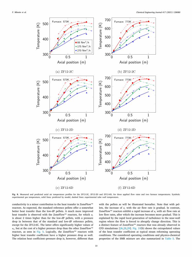
Chemical Engineering Journal 417 (2021) 128080F. Minette et al.
ide𝛼rhT
Fig. 8. Measured and predicted axial air temperature profiles for the ZF12-2C, ZF12-2D and ZF12-6D, for three applied flow rates and two furnace temperatures. Symbols:experimental gas temperature, solid lines: predicted by model, dashed lines: experimental tube wall temperature.
wlZ
conductivity is a minor contribution to the heat transfer in ZoneFlowtm
reactors. As expected, the standard reference pellets offer a somewhatbetter heat transfer than the low-dP pellets. A much more improvedheat transfer is observed with the ZoneFlowtm reactors, for which 𝛼𝑖s about 2 times higher than for the low-dP pellets, with a pressurerop in between that of the standard and low-dP reference pellets,xcept for the ZF12-6C. The latter offers significantly higher values of𝑖, but at the cost of a higher pressure drop than the other ZoneFlowtm
eactors, as seen in Fig. 5. Logically, the ZoneFlowtm reactors withigher heat transfer coefficient have a higher pressure drop as well.he relation heat coefficient–pressure drop is, however, different than
10
ith the pellets as will be illustrated hereafter. Note that with pel-ets, the increase of 𝛼𝑖 with the air flow rate is gradual. In contrast,oneFlowtm reactors exhibit a rapid increase of 𝛼𝑖 with air flow rate at
low flow rates, after which the increase becomes more gradual. This isexplained by the rapid local generation of turbulence in the near-wallregion where the flow is forced to abruptly change direction. This isa distinct feature of ZoneFlowtm reactors that was already observed inCFD simulations [26,28,29]. Fig. 10(b) shows the extrapolated valuesof the heat transfer coefficient at typical steam reforming operatingconditions. The considered operating conditions and physico-chemicalproperties of the SMR mixture are also summarized in Table 5. The

Chemical Engineering Journal 417 (2021) 128080F. Minette et al.
Fig. 9. Measured and predicted axial air temperature profiles for the ZF14-2D86, ZF14-2D84, for three applied flow rates and two furnace temperatures. Symbols: experimentalgas temperature, solid lines: predicted by model, dashed lines: experimental tube wall temperature.
exact same trends are observed. Under these conditions, radiation isalso expected to play a significant role in ZoneFlowtm reactors [26,28]ensuring even better heat transfer performance compared to pellets.
The diagram in Fig. 11 illustrates the relative heat transfer coeffi-cient versus the relative pressure drop for the standard pellets and theZoneFlowtm reactors. Performance is compared to the reference low-dP pellets. The open symbols are for typically tested conditions, withan air flow rate of 175 Nm3/h (see Fig. 10(a)). The filled symbolsare for typical steam reforming operating conditions with a flow rateof 500 Nm3/h (see Fig. 10(b)). The physico-chemical properties areidentical to those used in Fig. 10 and reported in Table 5. The stan-dard reference pellets provide a heat transfer coefficient approximately25%–30% higher than that of low-dP pellets, but with a pressure dropthat is approximately 90% higher. The ZF12-2C and ZF12-2D havesimilar but slightly higher pressure drop, respectively 10 and 25%,than the low-dP reference pellets, but the heat transfer coefficient isslightly more than doubled compared to the latter. The ZF14-2D84 andZF14-2D86 provide very similar pressure drop than the ZF12-2C andZF12-2D respectively, with the heat transfer coefficient also slightlymore than doubled compared to the low-dP reference pellets. The ZF12-6D provides even better heat transfer, but the pressure drop is around 2times higher than that of the low-dP pellets and around 1.1 times highercompared to the standard reference pellets. This does not necessarilymean that the integral or overall pressure drop over a ZF12-6D reactorwill be higher than that with pellets. This depends on the length ofthe reactor and, for given throughput, improved heat transfer allowsto shorten the reactor provided a sufficiently active catalyst is used.
11
Fig. 12 illustrates again the different relation between heat transfer
and pressure drop for the ZoneFlowtm reactors than for pellets. Thegraph clearly shows that at equivalent pressure drop, heat transfer twoto three times more efficient can be achieved with the ZoneFlowtm
reactors compared to the reference pellets.
5. Conclusions
The pressure drop and heat transfer performance of annularZoneFlowtm reactors of different designs and of standard and low-pressure drop reference pellets was experimentally studied and cor-relations for the friction factor, the heat transfer coefficient and theirparameters derived from experimental data. The ZoneFlowtm reactordesigns vary by the annulus width and the number of collars or disksthat are mounted on the central rod to suspend the annular structuredcasing. Measurements were carried out with air at atmospheric pressureand in a wide air flow rate range. The pressure drop in the ZoneFlowtm
reactor is well described by the Fanning-type equation. With thereference pellets, the relation of Hicks (1970) gave a good fit withre-estimated parameters. Heat transfer measurements were performedusing a constant furnace temperature which was varied between 100and 500 ◦C. The process gas and tube wall temperature were measuredat six axial positions. The latter were imposed in the regression.Standard correlations for the Nusselt number with optimized parametervalues were capable of reproducing the measured axial air temperatureprofiles. For the ZoneFlowtm reactors, a resistance-type model for thestatic contribution to heat transfer had to be first derived from 3Dnumerical simulations. These confirm that thermal conduction in thesolid internals has a minor contribution to the overall heat transfer in
tm
ZoneFlow reactors, which by design have a very high void fraction.
Chemical Engineering Journal 417 (2021) 128080
12
F. Minette et al.
Fig. 10. Comparison of the predicted heat transfer coefficients 𝛼𝑖 versus flow rate for the reference pellets and the ZoneFlowtm reactors using the derived correlations, for (a)typically tested operating conditions (flow of air at 300 ◦C and atmospheric pressure) and typically commercially applied SMR operating conditions (30 bar and 700 ◦C). SeeTable 5 for the considered physico-chemical properties.
Fig. 11. Relative heat transfer coefficient versus relative pressure drop of the ZoneFlowtm reactors and the standard pellets compared to the low-dP pellets. Open symbols: typicalexperimentally tested conditions (air at atmospheric pressure and 300 ◦C) at a flow rate of 175 Nm3/h, filled symbols: typical commercially applied SMR conditions (SMR mixtureat 30 bar and 700 ◦C) at a flow rate of 500 Nm3/h. See Table 5 for the physico-chemical properties.

Chemical Engineering Journal 417 (2021) 128080F. Minette et al.
3
arondat1ttl1itb
D
peecttt
A
Fig. 12. Predicted relationship pressure drop versus heat transfer for the reference pellets and the ZoneFlowtm reactors, for typically tested operating conditions: flow of air at00 ◦C and atmospheric pressure and flow rate between 5 and 340 Nm3/h. See Table 5 for the considered physico-chemical properties.
The data and analysis have shown that ZoneFlowtm reactors offerdistinct advantage when comparing the heat transfer–pressure drop
elation to that of conventional pellets and that modifying the numberf collars or disks that suspend the annular structured casing, or the an-ulus width, are efficient ways to vary the heat transfer versus pressurerop advantage. Conical collars or easier to manufacture disks providevery similar effect on heat transfer and pressure drop. By adapting
heir outer diameter, an identical casing can be used in the 12 mm and4 mm-annulus width ZoneFlowtm reactors. Most ZoneFlowtm reactorsested offer a circa 100% increased heat transfer coefficient comparedo the low-dP reference pellets, with a pressure drop between that ofow-dP and standard reference pellets. The ZoneFlowtm design with the2 mm annulus and 6 disks per casing element offers an even higherncrease of the heat transfer coefficient, at the cost of a pressure drophat is about 100% higher than that of the standard reference pellets,ut shortening the reactor could be considered.
eclaration of competing interest
One or more of the authors of this paper have disclosed potential orertinent conflicts of interest, which may include receipt of payment,ither direct or indirect, institutional support, or association with anntity in the biomedical field which may be perceived to have potentialonflict of interest with this work. For full disclosure statements refero https://doi.org/10.1016/j.cej.2020.128080.The authors would likeo thank ZoneFlow Reactor Technologies for the financial support ofhe research project.
cknowledgments
This research was financed by ZoneFlowtm Reactor Technologies,LLC. Computational resources have been provided by the Consortiumdes Équipements de Calcul Intensif (CECI), funded by the Fonds de laRecherche Scientifique de Belgique (F.R.S-FNRS), Belgium under GrantNo. 2.5020.11 and by the Walloon Region, Belgium.
References
[1] J.A. Moulijn, M. Makkee, A. Van Diepen, Chemical Process Technology, JohnWiley & Sons Ltd, Chichester, 2001.
[2] C.H. Bartholomew, R.J. Farrauto, Fundamentals of Industrial Catalytic Processes,second ed., John Wiley & Sons, INC., Hoboken, New Jersey, 2006.
[3] W.E. Liss, Impacts of shale gas advancements on natural gas utilisation in theUnited States, Energy Tehcnol. 2 (2014) 953–967.
[4] W. Liss, Demand Outlook: a golden age of natural gas, Chem. Eng. Prog. 108(2012) 35–40.
13
[5] E. McFarland, Unconventional chemistry for unconventional natural gas, Science338 (2012) 341–342.
[6] R.S. Middleton, R. Gupta, J.D. Hyman, H.S. Viswanathan, The shale gas rev-olution: Barriers, sustainability, and emerging opportunities, Appl. Energy 199(2017) 88–95.
[7] V. Arora, Y. Cai, U.S. natural gas exports and their global impacts, Appl. Energy120 (2014) 95–103.
[8] M. Melikoglu, Shale gas: Analysis of its role in the global energy market, Renew.Sust. Energ. Rev. 37 (2014) 460–468.
[9] I. Dybkjaer, K. Aasberg-Petersen, Synthesis gas technology: Large-scaleapplications, Can. J. Chem. Eng. 94 (2016) 607–612.
[10] J.R. Rostrup-Nielsen, J. Sehested, Steam reforming for hydrogen the process andthe mechanism, Fuel Chem. Div. Prepr. 48 (2003) 218–219.
[11] M.N. Perdernera, J. Pina, D.O. Borio, V. Bucala, Use of a heterogeneous two-dimensional model to improve the primary steam reformer performance, Chem.Eng. J. 94 (2003) 29–40.
[12] A.G. Dixon, Local transport and reaction rates in a fixed bed reactor tube:Endothermic steam methane reforming, Chem. Eng. Sci. 168 (2017) 156–177.
[13] A.G. Dixon, Fixed bed catalytic reactor modelling: the radial heat transferproblem, Can. J. Chem. Eng. 90 (2012) 507–527.
[14] Xu, G.F. Froment, Methane steam limitations and reforming: II. Diffusionalreactor simulation, AIChE J. 35 (1989) 97–103.
[15] J.R.H. Ross, Large-scale catalytic reactors, in: Heterogeneous Catalysis, 2012, pp.143–169.
[16] A.G. Dixon, M.E. Taskin, M. Nijemeisland, E.H. Stitt, Wall-to-particle heattransfer in steam reformer tubes: CFD comparison of catalyst particles, Chem.Eng. Sci. 63 (2008) 2219–2224.
[17] K. Pangarkar, T.J. Schildhauer, J.R. van Ommen, J. Nijenhuis, J.A. Moulijn, F.Kapteijn, Experimental and numerical comparison of structured packings with arandomly packed bed reactor for Fischer–Tropsch synthesis, Catal. Today 147S(2009) S2–S9.
[18] L. Fratalocchi, C.G. Visconti, G. Groppi, L. Lietti, E. Tronconi, Intensifying heattransfer in Fischer–Tropsch tubular reactors through the adoption of conductivepacked foams, Chem. Eng. J. 349 (2018) 829–837.
[19] D. Vervloet, F. Kapteijn, J. Nijenhuis, J.R. van Ommen, Process intensificationof tubular reactors: Considerations on catalyst hold-up of structured packings,Catal. Today 216 (2013) 111–116.
[20] C.G. Visconti, G. Groppi, E. Tronconi, Highly conductive packed foams: Anew concept for the intensification of strongly endo- and exo-thermic catalyticprocesses in compact tubular reactors, Catal. Today 273 (2016) 178–186.
[21] O. Sanz, I. Velasco, I. Reyero, I. Legorburu, G. Arzamendi, L.M. Gandia, M.Montes, Effect of the thermal conductivity of metallic monoliths on methanolsteam reforming, Catal. Today 273 (2016) 131–139.
[22] Johnson Matthey buys Catacel, to grow steam methane reforming, Fuel CellsBull. (Issue 10) (2014) 9–10.
[23] M. Basin, D. Gary, W. Whittenberger, J. Shah, Increased steam methane reformerthroughput: Switching to a foil based catalyst technology raised throughputsubstantially for a hydrogen producer, 2017, https://www.catacel.com.
[24] W. Whittenberger, Permanent, high performance, drop-in replacement catalystfor steam reforming hydrogen plants, 2010, https://www.catacel.com.
[25] ZoneFlowTM Reactor Technologies, LLC - catalyst for steam methane reforming,2007, https://www.zoneflowtech.com.

Chemical Engineering Journal 417 (2021) 128080F. Minette et al.
[26] J. De Wilde, G.F. Froment, Computational fluid dynamics in chemical reactoranalysis and design: Application to the ZoneFlowTM reactor for methane steamreforming, Fuel 100 (2012) 48–56.
[27] J. Xu, G.F. Froment, Methane steam reforming methanation and water-gas shift:I. Intrinsic kinetics, AIChE J. 35 (1989) 88–96.
[28] J. De Wilde, G.F. Froment, Modeling of dual-zone structured reactors for naturalgas steam reforming, Ind. Eng. Chem. Res. 52 (2013) 14055–14065.
[29] J. De Wilde, High heat transfer low pressure drop structured catalytic reactorsfor steam methane reforming, in: 14th AIChE Annual Meeting, Atlanta, GA, USA,November 2014, pp. 16-21.
[30] G.F. Froment, K.B. Bischoff, J. De Wilde, Chemical Reactor Analysis and Design,third ed., Wiley, 2010.
[31] R.E. Hicks, Pressure drop in packed beds of spheres, Ind. Eng. Chem. Fundam.9 (1970) 500–502.
[32] S. Ergun, Fluid flow through packed columns, Chem. Eng. Prog. 48 (1952) 89–94.[33] D. Handley, P.J. Heggs, Momentum and heat transfer mechanisms in regular
shaped packings, Trans. Inst. Chem. Eng. (1968) T251.[34] C.A. Wentz Jr, G. Thodos, Pressure drops in the flow of gases through packed
and distended beds of spherical particles, AIChE J. 9 (1963) 81–84.
14
[35] L. Giani, G. Groppi, E. Tronconi, Heat transfer characterization of metallic foams,Ind. Eng. Chem. Res. 44 (2005) 9078–9085.
[36] A.P. de Wasch, G.F. Froment, A two dimensional heterogeneous model for fixedbed catalytic reactors, Chem. Eng. Sci. 26 (1971) 629–634.
[37] A.P. de Wasch, G.F. Froment, Heat transfer in packed beds, Chem. Eng. Sci. 27(1972) 567–576.
[38] D. Kunii, J.M. Smith, Heat transfer characteristics of porous rocks, AIChE J. 6(1960) 71–78.
[39] A.G. Dixon, D.L. Cresswell, Theoretical prediction of effective heat transferparameters in packed beds, AIChE J. 25 (1979) 663–676.
[40] A.G. Dixon, M. Nijemeisland, CFD as a design tool for fixed-bed reactors, Ind.Eng. Chem. Res. 40 (2001) 5246–5254.
[41] M. Bracconi, M. Ambrosetti, M. Maestri, G. Groppi, E. Tronconi, A fundamentalanalysis of the influence of the geometrical properties on the effective thermalconductivity of open-cell foams, Chem. Eng. Process. 129 (2018) 181–189.
[42] M.E. Aerov, N.N. Umnik, Heat transfer from the tubes with packed beds, ZhurnalTech. Phiziki 21 (1951) 1364–1371.
[43] C.-H. Li, B.A. Finlayson, Heat transfer in packed beds - a reevaluation, Chem.Eng. Sci. 32 (1977) 1055–1066.