Embed Size (px)
Citation preview

1
Specifications are subject to change without notice. “This product is designed for general industrial use.”
No. SS2-ACP110-0100
Model ACP_ _ _
Pressure-Balanced Cage type Control Valve
11th edition
OVERVIEWThe model ACP pressure-balanced cage type control valves are designed for heavy duty service.The valve plug employs a pressure balance function to con-trol high differential pressure fluid with small actuator force.The ACP_ _ _ realizes seat leakage performance as single seat valve by seal-ring structure.In addition, the ACP_ _ _ is equipped the cage plug with a scraper ring to prevent a malfunction caused by foreign object enter between the cage plug and the cage.The actuator is adopted a compact and powerful diaphragm motor.The ACP_ _ _ is widely applicable for reliable control of high or low temperature, high differential pressure process lines where dynamic stability, dynamic stability, low noise, anti-cavitation/flashing are required.Model ACP is compliant to Functional Safety Standard (IEC61508).
SPECIFICATIONSBody
TypeStraight-through, cast globe valve
Nominal size1-1/2, 2, 2-1/2, 3, 4, 5, 6, 8, 10, 12 inches
Pressure rating and End connection
Connection type Pressure ratingApplicable standard
8 inches or less 10, 12 inches
FFJIS10K JIS B2210-1984 JIS B2212-1972ANSI Class 125 ANSI B16.5-1981 ANSI B16.5-1968JPI Class125 JPI-7S-15-1993 —
RF
JIS10KJIS B2210-1984
JIS B2212-1972JIS20K JIS B2214-1967JIS30K JIS B2215-1967ANSI Class 150, 300, 600 ANSI B16.5-1981 ANSI B16.5-1968
JPI Class 150, 300, 600 JPI-7S-15-1993 JPI-7S-15-1993
RJ, LGANSI Class 150, 300, 600 ANSI B16.5-1981 ANSI B16.5-1968
JPI Class 150, 300, 600 JPI-7S-15-1993 JPI-7S-15-1993
Tongue and groove (groove)
Male and female (female)
JIS16K, 20K, 30K, 40K JIS B2202-1984 —
• Welded end; SW (1-1/2, 2 inches), BW (2-1/2 to 8 inches)
MaterialFor body/trim material combinations and operating tem-perature ranges, refer to Table 1, Table 5, Table 6, Table 7 and Table 8.
BonnetPlain bonnet −17 to +230 °C —
Extension bonnet Type 1 −45 to −17 °C
+230 to +400 °C —
Extension bonnet Type 2*−100 to −45 °C Integral cast type
−196 to −100 °C Welded type
Bellows type −50 to +350 °CFormed or welded bellows Detail is showing in Fig. 3
Note: 1. Take care not to exceed the operating temperature ranges specified for respective materials.
2. * Nominal size 10 and 12 inches are optional specification.
Gland typeBolted gland
Grease• Grease not provided
V shaped PTFE* packing or PTFE* yarn packing
• Grease provided Graphite packing
* PTFE: Polytetrafluoroethylene

Azbil CorporationNo. SS2-ACP110-0100
2
Gasket
General/Low temp. High temperature Oil free treatment
Between body and
bonnet
Serrated gasketV543
Serrated gasketV543
Serrated gasket (PTFE coating)V543 (PTFE)
For upper cage
Serrated gasketV543
Serrated gasketV543
Serrated gasket (PTFE coating)V543 (PTFE)
For bottom cage
Spiral wound gasketV8590F Not necessary Spiral wound gasket
V7590
TrimValve plugSingle seated pressure balanced type
Cage• High-flow characteristics
• Metal seat (For flow characteristics, refer to Figure 1.)
• Equal percentage (%V)
• Linear (LV)
MaterialFor body/trim material combinations and operating tem-perature ranges, refer to Table 1, Table 5, Table 6, Table 7 and Table 8.Note: For fluid conditions that require CoCr-A, refer to Figure 2.
ActuatorModel
Single acting diaphragm actuator HA_ _, VA5_Spring type piston actuator PSA6R / PSA7RDouble acting piston actuator DAP560
ActionDirect or reverse action
Diaphragm
Actuator Model Material
HA_ _ Cloth embedded ethylene propylene rubberVA5_ Cloth embedded chloroprene rubber
Spring range
Actuator Model Spring range
HA_ _ 20 to 98 kPa {0.2 to 1.0 kgf/cm2} 80 to 240 kPa {0.8to 2.4 kgf/cm²}
VA5_ 40 to 200 kPa {0.4 to 2.0 kgf/cm2} 80 to 240 kPa {0.8 to 2.4 kgf/cm2}
PSA6R 200 to 340 kPa {2.0 to 3.5 kgf/cm2} 200 to 390 kPa {2.0 to 3.9 kgf/cm2}
PSA7R 200 to 340 kPa {2.0 to 3.5 kgf/cm2}
Supply pressureActuator Model Supply pressure
HA_ _ 140 to 390 kPa {1.4 to 4.0 kgf/cm2}
VA5_ 270 kPa {2.8 kgf/cm2}
PSA6R 400, 500 kPa {4, 5 kgf/cm2}PSA7R 400, 500 kPa {4, 5 kgf/cm2}
DAP560 500 kPa {5 kgf/cm2}
Note: Allowable differential pressure varies depending on spring range and air supply pressure.
Air connectionActuator Model Connection
HA_ _ Rc1/4 or 1/4NPT internal thread
PSA6R PSA7R VA5_
DAP560
Standard : Rc1/4 or 1/4NPT internal thread Rc1/4 or 1/4NPT is adapter use on Rc1/2 in 1/2NPT internal thread. Option : Rc3/8 or 3/8NPT adapter is possible R1/2 or 1/2NPT is possible without adapter.
Ambient temperature−30 to +70 °C
Valve actionAir-to-close (Direct action actuator is combined.) Air-to-open (Reverse action actuator is combined.)
Functional Safety Standard (IEC61508) conformity:SIL3 capable - certified by exida Consulting LLC
Optional accessoriesPositioner*, pressure regulator with filter, hand wheel*, limit switch, solenoid valve, motion transmitter, booster relay, lock-up valve, and others.Note: 1. For optional items, refer to the specification sheets and
installation drawings of the respective accessories.
2. Accessories with the asterisk mark (*) are selected from among the following types depending on the actuators to be combined.
Actuator Model
Positioner Hand wheel
P/P I/P Top Side
HA2 to 4HTP-_ _
AVP7_ _AVP3_ _ AVP2_ _
MountedMountedVA5
PSA6R HTP-_ _ VPP0_ - _
—PSA7RVPP0_ - _ Mounted
(Hydraulic)DAP560

No. SS2-ACP110-0100Azbil Corporation
3
Additional specifications (by special order)• Special inspection
Flow characteristics inspection, material inspection (Material certificate), non-destructive inspection, steam inspection, low-temperature inspection
• With drain plug• Double gland• Oil/water free treatment• Copper free treatment• Stainless steel (SUS304) atmospheric-exposed nuts and
bolts• Yoke material SCPH2• Special air piping and joint• Sand-/dust preventive measure• Saline damage countermeasure• Cold-area use specification• Tropical-area use specification• Vacuum service
PerformanceRated Cv valueRefer to Table 2 and Table 3.
Flow characteristicsRefer to Figure 1.
Inherent range ability• 50 : 1 • Optional 75 : 1 for full port size
Allowable differential pressureTemperature range Refer to Table
−196 to +230 °C Table 9 and Table 10
+230 to +400 °C Table 11 and Table 12
Leakage specification
IEC 60534-4:2006 or JIS B 2005-4:2008
Class IV: Leakage less than 0.01 % of maximum valve capacity.
0.05 % of maximum valve capacity.
Refer to following table about combination of port size and seat leakage specification.
Operating temperature
Nominal size
(inch)
Port size Seat leakage
−196 to +230 °C 1-1/2 to 12
FullClass IV: 0.01 % of Cv value
Reduced
+230 to +400 °C
1-1/2 , 2Full 0.05 % of Cv value
Reduced —
2-1/2, 3Full Class IV: 0.01 % of Cv value
Reduced —
4 to 12Full
Class IV: 0.01 % of Cv valueReduced
Hysteresis error
Actuator Model HA_ _, VA5_, DAP560 PSA6R/7R
Without positioner ± 3 %F.S. ± 9 %F.S.
With positioner ± 1 %F.S. ± 2 %F.S.
Linearity
Actuator Model HA_ _, VA5_, DAP560 PSA6R/7R
Without positioner ± 5 %F.S. ± 9 %F.S.
With positioner ± 1 %F.S. ± 2 %F.S.
Note 1. When positioner is not provided, operating performance may vary depending on type of packing used.
DimensionsRefer to Figure 6, Table 13 and Table 14.
WeightRefer to Table 15.
Actuator orientationRefer to Figure 7.
FinishBlue (Munsell 10B5/10) or silver, or their specified colors.
Table 1. Body/trim material combinations and operating temperature ranges (°C) Body material
Trim material
JIS SCPH2 SCPH21 SCS61 SCPL1 SCS13A SCS14A
ASTM A216WCB A217WC6 A217C5 A352LCB A351CF8 A351CF8M
ASTM A351CF8M* −5 to +230 −5 to +230 −5 to +230 −45 to +230 −196 to +230 −196 to +230ASTM A351CF8M* CoCr-A −5 to +400 −5 to +400 −5 to +400 −45 to +350 −196 to +400 −196 to +400
JIS SCS24 −5 to +400 −5 to +400 −5 to +400 −5 to +350 — —* Equivalent to SCS14A.

4
Azbil CorporationNo. SS2-ACP110-0100
Cv value and travelTable 2. CV value and travel (temperature range: −45 to +230 °C)
Nominal size (inch) 1-1/2 2 2-1/2 3 4Port size (inches) 1 1-1/4 1-1/2 1-1/4 1-1/2 2 1-1/2 2 2-1/2 2 2-1/2 3 2-1/2 3 4
Rated Cv value%V 10 26 29 18 31 56 23 40 78 59 78 110 63 103 158LV — — 34 — — 60 — — 81 — — 115 — — 203
Rated travel (mm) 25 25 38 38 38
Nominal size (inch) 5 6 8 10 12Port size (inches) 3 4 5 4 5 6 5 6 8 6 8 10 8 10 12
Rated Cv value%V 88 175 250 179 261 322 275 360 610 395 750 1000 800 1000 1440LV — — 250 — — 371 — — 795 — — 1000 — — 1440
Rated travel (mm) 50 50 75 100 100
Table 3. CV value and travel (temperature range: +230 to +400 °C)Nominal size (inch) 1-1/2 2 2-1/2 3 4
Port size (inches) 1 1-1/4 1-1/2 1-1/4 1-1/2 2 1-1/2 2 2-1/2 2 2-1/2 3 2-1/2 3 4
Rated Cv value%V — — 29 — — 56 — — 78 — — 110 63 103 158LV — — 24 — — 52 — — 78 — — 110 63 103 150
Rated travel (mm) 25 25 38 38 38
Nominal size (inch) 5 6 8 10 12Port size (inches) 3 4 5 4 5 6 5 6 8 6 8 10 8 10 12
Rated Cv value%V 99 175 250 179 261 322 275 360 610 395 750 1000 800 1200 1440LV 99 175 250 179 261 350 275 360 600 — — 1000 — — 1440
Rated travel (mm) 50 50 75 100 100
100
50
20
10
5
20 20 40 60 80 100
Travel (%)
Cv v
alue
(%)
a. Equal percentage characteristics (%V)
100
80
60
40
20
00 20 40 60 80 100
Travel (%)
Cv v
alue
(%)
b. Linear characteristics (LV)Figure 1. Flow characteristics
Note: The above graphs indicate typical flow characteristics.
1470{15}
kPa{kgf/cm2}
981{10}
490{5}
0−196 0 +100 +200 +300
CoCr-A
Nor
mal
diff
eren
tial p
ress
ure
Fluid temperature (°C)
3
2
1
-50 -30 +300 +350
Max
imum
pre
ssur
e(M
Pa)
Welded bellows
Formed bellows type II
Formed bellows type I
Fluid temperature ( C)Figure 2. Temperature/normal differential pressure
ranges requiring CoCr-AFigure 3. Bellows Type by Temperature and Pressure
RangesNote: For cavitation/flashing service or oil free service, CoCr-A is
recommended regardless of temperature and differential pressure.Note) Bellows type are classified into Formed bellows type I, II and
welded bellows by temperature and pressure ranges. Please refer to No. SS2-BSL100-0100 about detail of bellows
specification.

5
No. SS2-ACP110-0100Azbil CorporationTable 4. Gland packingAccording to your application, select appropriate type of gland packing from the following:
Application Packing TypeFluid temperature range
Maximum working pressure
General use (Various chemical, acid and alkali)
PTFE fiber yarn packing with carbon fiber core packing [P4519]-17 to +230 °C10MPa Max.
General use or oil free(Various chemical, acid and alkali)
V shaped pure PTFE packing [Pure PTFE]-196 to + 230 °C
10MPa Max.Vacuum and General use or oil free(Various chemical, acid and alkali)
V shaped pure PTFE packing (Dir. + Rev.)[Pure PTFE (Dir. + Rev.)]
-196 to +230 °C10MPa Max.
Low or standard temperature(Various chemical, acid and alkali, LNG, etc.)
V shaped pure PTFE packing +PTFE fiber yarn packing or PTFE braided packing
[Pure PTFE +PTFE fiber]
-196 to +230 °C
10MPa Max.
High temperature
Expanded graphite packing + Expanded graphite yarn packing *1
[P6610CH+P6528]+230 to +500 °C
43MPa Max.Expanded graphite packing + Carbon fiber reinforced expanded
graphite packing *1 [P6610CH+M8590]+500 to +566 °C
43MPa MAX.Measures against VOC *2 exhaust regulation
[ISO15848-1 compliant low emission packing system]
Packing with Live Load structure *3-17 to +350 °C
15.5 MPa Max.
*1. Grease provided It cannot be applied to PSA1 actuator (spring range 20 to 98 kPa).*2. Volatile Organic Compound*3. Refer to special spec sheet No.SS2-SSL100-0100 about detail of Low emission gland packing.
For general use
[P4519]
For general use or oil free
[V shaped pure PTFE]
For vacuum and general
use or oil free
[V shaped pure PTFE
(Dir.+Rev.)]
For high temperature
[P6610CH+P6528]*1 Grease provided by lubricator
Measures against VOC
exhaust regulation
[Packing with Live
Load structure]
*1
Figure 4. Gland Packing structure
6
Azbil CorporationNo. SS2-ACP110-0100
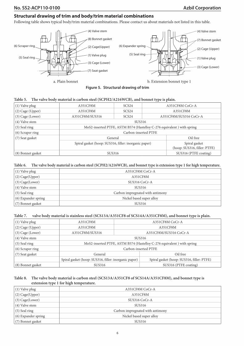
Structural drawing of trim and body/trim material combinationsFollowing table shows typical body/trim material combinations. Please contact us about materials not listed in this table.
(4) Valve stem
(8) Bonnet gasket
(5) Seal ring
(2) Cage(Upper)
(3) Cage (Lower)
(7) Seat gasket
(6) Scraper ring
(1) Valve plug
a. Plain bonnet
(4) Valve stem
(7) Bonnet gasket
(2) Cage (Upper)
(3) Cage (Lower)
(1) Valve plug
(6) Expander spring
(5) Seal ring
b. Extension bonnet type 1Figure 5. Structural drawing of trim
Table 5. The valve body material is carbon steel (SCPH2/A216WCB), and bonnet type is plain.(1) Valve plug A351CF8M SCS24 A351CF8M CoCr-A(2) Cage (Upper) A351CF8M SCS24 A351CF8M(3) Cage (Lower) A351CF8M/SUS316 SCS24 A351CF8M/SUS316 CoCr-A(4) Valve stem SUS316(5) Seal ring MoS2-inserted PTFE, ASTM B574 (Hastelloy C-276 equivalent ) with spring(6) Scraper ring Carbon-inserted PTFE(7) Seat gasket General Oil free
Spiral gasket (hoop: SUS316, filler: inorganic paper) Spiral gasket (hoop: SUS316, filler: PTFE)
(8) Bonnet gasket SUS316 SUS316 (PTFE coating)
Table 6. The valve body material is carbon steel (SCPH2/A216WCB), and bonnet type is extension type 1 for high temperature.(1) Valve plug A351CF8M CoCr-A(2) Cage(Upper) A351CF8M(3) Cage(Lower) SUS316 CoCr-A(4) Valve stem SUS316(5) Seal ring Carbon impregnated with antimony(6) Expander spring Nickel based super alloy(7) Bonnet gasket SUS316
Table 7. valve body material is stainless steel (SCS13A/A351CF8 of SCS14A/A351CF8M), and bonnet type is plain.(1) Valve plug A351CF8M A351CF8M CoCr-A(2) Cage (Upper) A351CF8M A351CF8M(3) Cage (Lower) A351CF8M/SUS316 A351CF8M/SUS316 CoCr-A(4) Valve stem SUS316(5) Seal ring MoS2-inserted PTFE, ASTM B574 (Hastelloy C-276 equivalent ) with spring(6) Scraper ring Carbon-inserted PTFE(7) Seat gasket General Oil free
Spiral gasket (hoop: SUS316, filler: inorganic paper) Spiral gasket (hoop: SUS316, filler: PTFE)(8) Bonnet gasket SUS316 SUS316 (PTFE coating)
Table 8. The valve body material is carbon steel (SCS13A/A351CF8 of SCS14A/A351CF8M), and bonnet type is extension type 1 for high temperature.
(1) Valve plug A351CF8M CoCr-A(2) Cage(Upper) A351CF8M(3) Cage(Lower) SUS316 CoCr-A(4) Valve stem SUS316(5) Seal ring Carbon impregnated with antimony(6) Expander spring Nickel based super alloy(7) Bonnet gasket SUS316
7
No. SS2-ACP110-0100Azbil Corporation
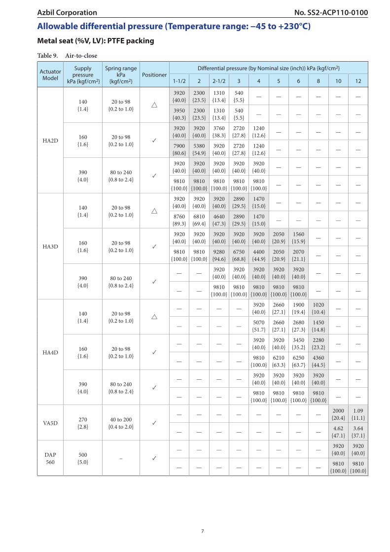
Allowable differential pressure (Temperature range: −45 to +230°C)Metal seat (%V, LV): PTFE packing
Table 9. Air-to-close
Actuator Model
Supply pressure
kPa {kgf/cm2}
Spring range kPa
{kgf/cm2}Positioner
Differential pressure (by Nominal size (inch)) kPa {kgf/cm2}
1-1/2 2 2-1/2 3 4 5 6 8 10 12
HA2D
140 {1.4}
20 to 98 {0.2 to 1.0}
3920 {40.0}
2300 {23.5}
1310 {13.4}
540 {5.5} — — — — — —
3950 {40.3}
2300 {23.5}
1310 {13.4}
540 {5.5} — — — — — —
160 {1.6}
20 to 98 {0.2 to 1.0}
✓
3920 {40.0}
3920 {40.0}
3760 {38.3}
2720 {27.8}
1240 {12.6} — — — — —
7900 {80.6}
5380 {54.9}
3920 {40.0}
2720 {27.8}
1240 {12.6} — — — — —
390 {4.0}
80 to 240 {0.8 to 2.4}
✓
3920 {40.0}
3920 {40.0}
3920 {40.0}
3920 {40.0}
3920 {40.0} — — — — —
9810 {100.0}
9810 {100.0}
9810 {100.0}
9810 {100.0}
9810 {100.0} — — — — —
HA3D
140 {1.4}
20 to 98 {0.2 to 1.0}
3920 {40.0}
3920 {40.0}
3920 {40.0}
2890 {29.5}
1470 {15.0} — — — — —
8760 {89.3}
6810 {69.4}
4640 {47.3}
2890 {29.5}
1470 {15.0} — — — — —
160 {1.6}
20 to 98 {0.2 to 1.0}
✓
3920 {40.0}
3920 {40.0}
3920 {40.0}
3920 {40.0}
3920 {40.0}
2050 {20.9}
1560 {15.9} — — —
9810 {100.0}
9810 {100.0}
9280 {94.6}
6750 {68.8}
4400 {44.9}
2050 {20.9}
2070 {21.1} — — —
390 {4.0}
80 to 240 {0.8 to 2.4}
✓— — 3920
{40.0}3920 {40.0}
3920 {40.0}
3920 {40.0}
3920 {40.0} — — —
— — 9810 {100.0}
9810 {100.0}
9810 {100.0}
9810 {100.0}
9810 {100.0} — — —
HA4D
140 {1.4}
20 to 98 {0.2 to 1.0}
— — — — 3920 {40.0}
2660 {27.1}
1900 {19.4}
1020 {10.4} — —
— — — — 5070 {51.7}
2660 {27.1}
2680 {27.3}
1450 {14.8} — —
160 {1.6}
20 to 98 {0.2 to 1.0}
✓— — — — 3920
{40.0}3920 {40.0}
3450 {35.2}
2280 {23.2} — —
— — — — 9810 {100.0}
6210 {63.3}
6250 {63.7}
4360 {44.5} — —
390 {4.0}
80 to 240 {0.8 to 2.4}
✓— — — — 3920
{40.0}3920 {40.0}
3920 {40.0}
3920 {40.0} — —
— — — — 9810 {100.0}
9810 {100.0}
9810 {100.0}
9810 {100.0} — —
VA5D 270 {2.8}
40 to 200 {0.4 to 2.0}
✓— — — — — — — — 2000
{20.4}1.09
{11.1}
— — — — — — — — 4.62 {47.1}
3.64 {37.1}
DAP 560
500 {5.0} − ✓
— — — — — — — — 3920 {40.0}
3920 {40.0}
— — — — — — — — 9810 {100.0}
9810 {100.0}

8
Azbil CorporationNo. SS2-ACP110-0100Table 10. Air-to-open
Actuator Model
Supply pressure
kPa {kgf/cm2}
Spring range
kPa {kgf/cm2}Positioner
Differential pressure (by Nominal size (inch)) kPa {kgf/cm2}
1-1/2 2 2-1/2 3 4 5 6 8 10 12
HA2R 270 {2.8}
80 to 240 {0.8 to 2.4}
✓
3920 {40.0}
3920 {40.0}
3920 {40.0}
3920 {40.0}
2840 {29.0} — — — — —
9810 {100.0}
8450 {86.2}
6540 {66.7}
4890 {49.9}
2890 {29.5} — — — — —
HA3R
140 {1.4}
20 to 98 {0.2 to 1.0}
1750 {17.8}
1360 {13.9} — — — — — — — —
1750 {17.8}
1360 {13.9} — — — — — — — —
270 {2.8}
80 to 240 {0.8 to 2.4}
✓— 3920
{40.0}3920 {40.0}
3920 {40.0}
3920 {40.0}
3920 {40.0}
2460 {25.1} — — —
— 9810 {100.0}
9810 {100.0}
9810 {100.0}
7340 {74.8}
4110 {41.9}
4140 {42.2} — — —
HA4R 270 {2.8}
80 to 240 {0.8 to 2.4}
✓— — — — 3920
{40.0}3920 {40.0}
3920 {40.0}
3540 {36.1} — —
— — — — 9810 {100.0}
9750 {99.4}
9810 {100.0}
7270 {74.1} — —
VA5R 270 {2.8}
80 to 240 {0.8 to 2.4}
✓— — — — — — — — 2450
{25.0}1470 {15.0}
— — — — — — — — 5840 {59.6}
4220 {43.0}
PSA6R 500 {5.0}
200 to 390 {0.2 to 4.0}
✓— — — — — — — — 3920
{40.0}3920 {40.0}
— — — — — — — — 9810 {100.0}
9810 {100.0}
PSA7R 400 {4.0}
200 to 340 {0.2 to 3.5}
✓— — — — — — — — 3920
{40.0}3920 {40.0}
— — — — — — — — 9810 {100.0}
9810 {100.0}
Note: 1. “ ” shows a model with standard actuator.
2. ✓: Positioner is necessary. : Can be operated either with or without positioner.
3. Take care not to cause the maximum allowable differential pressure to exceed the maximum operating pressure designated by ANSI B16. 34-1981 or JIS B2201-1984.
4. The upper figures denote the operating allowable differential pressure. The lower denote allowable differential pressure at full closure.
5. Combination of supply pressure 140 kPa and without positioner is able to be selected only for ON-OFF application.

9
No. SS2-ACP110-0100Azbil Corporation
Allowable differential pressure (Temperature range: +230 to +400°C)Metal seat (%V, LV): Graphite packing “P6610CH+P6528”
Table 11. Air-to-close
Actuator Model
Supply pressure kPa
{kgf/cm2}
Spring range kPa
{kgf/cm2}Positioner
Differential pressure (by Nominal size (inch)) kPa {kgf/cm2}
1-1/2 2 2-1/2 3 4 5 6 8 10 12
HA3D 390 {4.0}
80 to 240 {0.8 to 2.4}
✓
3920 {40.0}
3920 {40.0}
3920 {40.0}
3920 {40.0}
3920 {40.0}
3920 {40.0}
3920 {40.0} — — —
9810 {100.0}
9810 {100.0}
9630 {98.2}
9240 {94.2}
7600 {77.4}
7600 {77.4}
4290 {43.7} — — —
HA4D 390 {4.0}
80 to 240 {0.8 to 2.4}
✓— — — — 3920
{40.0}3920 {40.0}
3920 {40.0}
3920 {40.0} — —
— — — — 9810 {100.0}
9810 {100.0}
9050 {92.2}
7040 {71.7} — —
VA5D 270 {2.8}
80 to 240 {0.8 to 2.4}
✓— — — — — — — — 3060
{31.2}1280 {13.1}
— — — — — — — — 4360 {44.5}
3630 {37.0}
DAP 560
500 {5.0} — ✓
— — — — — — — — 3920 {40.0}
3920 {40.0}
— — — — — — — — 9810 {100.0}
9810 {100.0}
Table 12. Air-to-open
Actuator Model
Supply pressure kPa
{kgf/cm2}
Spring range kPa
{kgf/cm2}Positioner
Differential pressure (by Nominal size (inch)) kPa {kgf/cm2}
1-1/2 2 2-1/2 3 4 5 6 8 10 12
HA3R 270 {2.8}
80 to 240 {0.8 to 2.4}
✓
3920 {40.0}
3920 {40.0} 3420
{34.8}3030 {30.8}
3030 {30.8}
3030 {30.8}
1730 {17.6}
— — —
5760 {58.7}
4470 {45.5} — — —
HA4R 270 {2.8}
80 to 240 {0.8 to 2.4}
✓— — — — 3920
{40.0}3920 {40.0} 3760
{38.3}2930 {29.8}
— —
— — — — 6670 {68.0}
6670 {68.0} — —
VA5R 270 {2.8}
80 to 240 {0.8 to 2.4}
✓— — — — — — — — 3920
{40.0}2110 {21.5}
— — — — — — — — 4060 {41.4}
2110 {21.5}
PSA6R 400 {4.0}
200 to 340 {2.0 to 3.5}
✓— — — — — — — — 3920
{40.0}3920 {40.0}
— — — — — — — — 9810 {100.0}
9700 {98.9}
PSA7R 400 {4.0}
200 to 340 {2.0 to 3.5}
✓— — — — — — — — 3920
{40.0}3920 {40.0}
— — — — — — — — 9810 {100.0}
9810 {100.0}
Note: 1. “ ” shows a model with standard actuator.
2. ✓: Positioner is necessary. : Can be operated either with or without positioner.
3. Take care not to cause the maximum allowable differential pressure to exceed the maximum operating pressure designated by ANSI B16. 34-1981 or JIS B2201-1984.
4. The upper figures denote the operating allowable differential pressure. The lower denote allowable differential pressure at full closure.

10
Azbil CorporationNo. SS2-ACP110-0100
DIMENSIONS
Table 13. Face-to-face dimensions Unit: mm
Nominal size (inch)
A
JIS 10KFF, RF ANSI 125FF ANSI 150RF
JPI 150RF
JIS 16KRF
JIS 20KRF JIS 30KRF
ANSI 300RF JPI 300RF
JIS 40KRF ANSI 600RF
JPI 600RF
JIS 16K JIS 20K JIS 30K JIS 40K
Tongue and groove, male and female
1-1/2 222 231 235 251 235 236 248 2512 254 263 267 286 265 267 276 286
2-1/2 276 288 292 311 290 292 303 3113 298 313 317 337 310 317 326 3374 352 364 368 394 360 368 379 3945 403 425 425 457 — — — —6 451 465 473 508 475 473 486 5088 543 560 568 610 570 568 580 610
10 673 708 708 752 — — — —12 737 775 775 819 — — — —
Nominal size (inch)
A
ANSI 150RJJPI 150RJ
ANSI 300RJJPI 300RJ
ANSI 600RJJPI 600RJ
ANSI 300LGJPI 300LG
ANSI 600LGJPI 600LG
ANSI 150JPI 150SW, BW
ANSI 300JPI 300SW, BW
ANSI 600JPI 600SW, BW
1-1/2 235 248 251 244 248 251 251 2512 267 283 289 276 283 286 286 286
2-1/2 289 308 314 302 308 311 311 3113 311 333 340 327 333 337 337 3374 365 384 397 378 391 394 394 3945 416 441 460 441 460 425 425 4576 464 489 511 483 505 473 508 5088 556 584 613 578 606 568 610 610
10 686 724 756 — — — — —12 749 791 822 — — — — —

11
No. SS2-ACP110-0100Azbil CorporationTable 14. External dimensions Unit: mm
Nominal size (inch)
Actuator Model
HB B E
Plain bonnet Extension bonnet Type 1Extension bonnet Type 2 Bellows
bonnetIntegral cast type Welded type
1 -1/2HA2D, R 500 665 780 1020 660 281 267
70HA3D, R 590 760 875 1140 750 363 350
2HA2D, R 500 670 785 1025 660 281 267
80HA3D, R 595 760 875 1140 750 363 350
2 -1/2HA2D, R 575 745/755 880 1130 795 281 267
90HA3D, R 630 800/810 930 1180 850 363 350
3HA2D, R 580 755/765 900 1135 800 281 267
100HA3D, R 635 810/820 955 1190 855 363 350
4HA2D, R 610 810/820 915 1150 830 281 267
115HA3D, R 660 860/870 1020 1205 880 363 350HA4D, R 890 1100/1110 1255 1520 — 520 470
5HA3D, R 775 925 1265 1365 855 363 350
141HA4D, R 945 1095 1435 1535 1005 520 470
6HA3D, R 785 1020/1045 1250 1385 1075 363 350
170HA4D, R 955 1190/1215 1425 1570 1245 520 470
8HA4D, R 1090 1350 1580 1710 1340 520 470
220VA5D 1475 1740 2025 2155 — — 620VA5R 1585 1850 2145 2275 — — 620
10
VA5D 1760 2015 * — — — 620
300VA5R 1890 2145 * — — — 620
PSA6R 1815 2070 * — — — 476PSA7R * * * — — — 580
DAP560 1545 1800 * — — — 380
12
VA5D 1810 1960 * — — — 620
325VA5R 1940 2090 * — — — 620
PSA6R 1865 2015 * — — — 476PSA7R * * * — — — 580
DAP560 1595 1745 * — — — 380* Contact our representative.
B
H
E
A
B
Figure 6. Face-to-face and other dimensions

12
Azbil CorporationNo. SS2-ACP110-0100Table 15. Weight Unit: kg
Nominal size
(inch)
Actuator Model
WeightFlange type: JIS 10K, ANSI/JPI 150 Flange type: JIS 16K, 20K, 30K, ANSI/JPI 300
Plain bonnet
Extension Type 1 Bellows type
Extension Type 2 Plain bonnet
Extension Type 1 Bellows type
Extension Type 2Integral cast type Welded type Integral cast type Welded type
1-1/2 HA2D, R 31 34 37 39 36 39 42 44HA3D, R 43 46 49 51 48 51 54 56
2 HA2D, R 37 40 43 45 42 45 48 50HA3D, R 49 52 55 57 54 57 60 62
2-1/2 HA2D, R 43 47 51 53 48 52 56 58HA3D, R 55 59 63 65 60 64 68 70
3 HA2D, R 53 59 65 68 63 69 75 78HA3D, R 65 71 77 80 75 81 87 90
4HA2D, R 63 73 78 81 78 88 93 96HA3D, R 75 85 90 93 90 100 105 108HA4D, R 106 116 121 124 121 131 136 139
5 HA3D, R 132 140 154 157 142 150 164 167HA4D, R 168 176 190 193 178 186 200 203
6 HA3D, R 157 172 179 182 187 201 209 212HA4D, R 188 203 210 213 218 233 240 243
8HA4D, R 268 288 298 303 318 338 348 353
VA5D 370 390 400 405 420 440 450 455VA5R 395 415 425 430 445 465 475 480
10
VA5D 560 600 * * 690 710 * *VA5R 585 625 * * 715 735 * *
PSA6R * * * * * * * *PSA7R * * * * * * * *
DAP560 * * * * * * * *
12
VA5D 750 780 * * 900 920 * *VA5R 775 805 * * 925 945 * *
PSA6R * * * * * * * *PSA7R * * * * * * * *
DAP560 * * * * * * * *
Nominal size
(inch)
Actuator Model
WeightFlange type: JIS 40K, ANSI/JPI 600 Welded type: JIS 10K, 16K, 20K, 30K, ANSI/JPI 150, 300, 600
Plain bonnet
Extension Type 1 Bellows type
Extension Type 2 Plain bonnet
Extension Type 1 Bellows type
Extension Type 2Integral cast type Welded type Integral cast type Welded type
1-1/2 HA2D, R 44 47 50 52 36 39 42 44HA3D, R 56 59 62 64 64 51 54 56
2 HA2D, R 47 50 53 55 42 45 48 50HA3D, R 59 62 65 67 54 57 60 62
2-1/2 HA2D, R 65 69 73 75 48 52 56 58HA3D, R 77 81 85 87 60 64 68 70
3 HA2D, R 85 91 97 100 63 69 75 78HA3D, R 97 103 109 112 75 81 87 90
4HA2D, R 113 123 128 131 75 85 90 93HA3D, R 125 135 140 143 87 97 102 105HA4D, R 156 166 171 174 118 128 133 136
5 HA3D, R 187 195 209 212 135 143 157 160HA4D, R 223 231 245 258 168 179 190 193
6 HA3D, R 237 252 259 262 177 192 199 202HA4D, R 268 283 290 293 208 223 230 233
8HA4D, R 438 458 468 473 308 328 338 343
VA5D 540 560 570 575 410 430 440 445VA5R 565 585 595 600 435 455 465 470
10
VA5D 750 780 * * * * * *VA5R 775 805 * * * * * *
PSA6R * * * * * * * *PSA7R * * * * * * * *
DAP560 * * * * * * * *
12
VA5D 1000 1100 * * * * * *VA5R 1025 1125 * * * * * *
PSA6R * * * * * * * *PSA7R * * * * * * * *
DAP560 * * * * * * * ** Contact our representative.

13
No. SS2-ACP110-0100Azbil Corporation(HA and VA5 Actuator)
Side-mountedhand wheel
Side-mountedhand wheel
Flowdirection
Flowdirection
Positioner
No. 1 (Standard type)
Side-mountedhand wheel
Flowdirection
Flowdirection
Positioner
Positioner
No. 2
Side-mountedhand wheel
Flowdirection
Flowdirection
Positioner
No. 3
Side-mountedhand wheel
Flowdirection
Flowdirection
Positioner
No. 4
(PSA6R Actuator)
Side handle
Flowdirection
Flowdirection
Positioner
No. 1 (Standard type)
Side handle
Flowdirection
Flowdirection
Positioner
Side handle Positioner
No. 2
Side handle
Flowdirection
Flowdirection
Positioner
No. 3
Side handle
Flowdirection
Flowdirection
Positioner
Positioner
No. 4
(PSA7R and DAP560 Actuator)
Sidehandle
Flowdirection
Flowdirection
Positioner
No. 1 (Standard type)
Sidehandle
Flowdirection
Flowdirection
Positioner
Positioner
No. 2
Sidehandle
Side handleFlowdirection
Flowdirection
Positioner
No. 3
Flowdirection
Flowdirection
Side handle
Positioner
Positioner
No. 4
Figure 7. Actuator orientation
Note: Indicate by position number when installation other than the standard type is required.
Ordering InformationWhen ordering, please specify;
1)2)3)4)5)6)7)8)9)
Model Number: ACPNominal size X Port sizeType and rating of end connectionsBody and trim material, necessity of hardeningType of bonnetValve and plug characteristicsType of actuator, air to diaphragmValve action (direct or reverse)Accessories (positioner, hand wheel, pressure regulator etc.)
10)11)12)13)
14)15)
Special requirement of degreasing, free from copper and etc.Name of flow mediumNormal flow and maximum required flowPressure of flow medium upstream and downstream pres sure at maximum and minimum, required flowTemperature and specific gravity of flow mediumViscosity of flow medium, inclusive or exclusive of slurry

14
Azbil CorporationNo. SS2-ACP110-0100

15
No. SS2-ACP110-0100Azbil Corporation

(16)
Please read “Terms and Conditions” from the following URL before ordering and use.https://www.azbil.com/products/factory/order.html
1-12-2 Kawana, FujisawaKanagawa 251-8522 Japan
https://www.azbil.com/
Specifications are subject to change without notice.
No part of this publication may be reproduced or duplicated without the prior written permission of Azbil Corporation.16
Azbil CorporationNo. SS2-ACP110-0100
1st edition: June 200111th edition: Nov. 2019