Embed Size (px)
Citation preview
It’s all at Albion
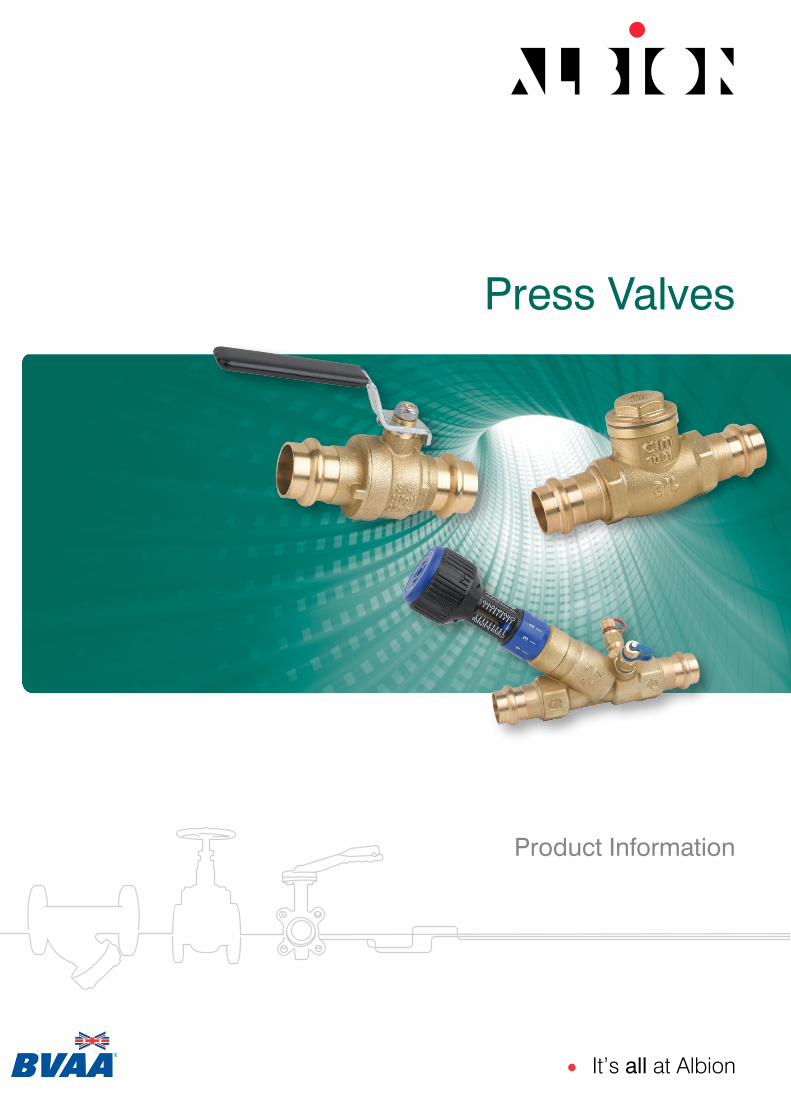
Product Information
Press Valves

Dimensions in mmThis data sheet is designed as a guide and should not be regarded as wholly accurate in every detail. We reserve the right to amend the specification of any product without notice.
Technical Data
ART 55 M & V Press
Max Pressure 16 Bar
Working Temperature -20ºC to +140ºC
1 Body DZR Brass 2 Screwed End DZR Brass 3 Ball Brass Chrome Plated 4 Ball Gaskets PTFE 5 Stem Brass 6 O-Ring FKM 70 SH 7 Anti-Friction Ring PTFE 8 Handle Steel 9 Washer Brass 10 Self-Locking Nut Steel 11 O-Ring EPDM 70 PEROX
N. Part Name Materials
Pressure / Temperature
0-20 20 40 60 80 10010-10 30 50 70 90 110 120 130 140 150 160 ºCTEMPERATURE
PR
ESSU
RE
bar
24
20
16
12
8
4
0
PN16 DZR Press Ball Valve Features• Universal M & V Press 15mm to 35mm• Dedicated M & V Profiles 42mm & 54mm (See diagram)• Full Bore • DZR Brass Body• PTFE Seats• EPDM ‘O’ Rings• Pre-Press Leak Detection• WRAS Approved
NB: Sizes 15mm to 35mm can be pressed with both ‘M’ and ‘V’ press jaws.Always use the appropriate ‘M’ or ‘V’ press sling to press sizes 42mm and 54mm
A 90 90 110 110 150 150B 47 52 57 65 81 89C (M Press) 78 91 99 107 133 155C (V Press) 78 91 99 107 133 163D (M Press) 22 25 27 27 32 33D (V Press) 22 25 27 27 32 37Kgs 0.19 0.31 0.49 0.72 1.17 1.72
DN 15 22 28 35 42 54
75
1
114
3
68 9 10
2
Ø DN
D Detailbelow
A
B
C
‘M’ Press(DN42)
‘M’ Press(DN54)
‘V’ Press(DN42+54)
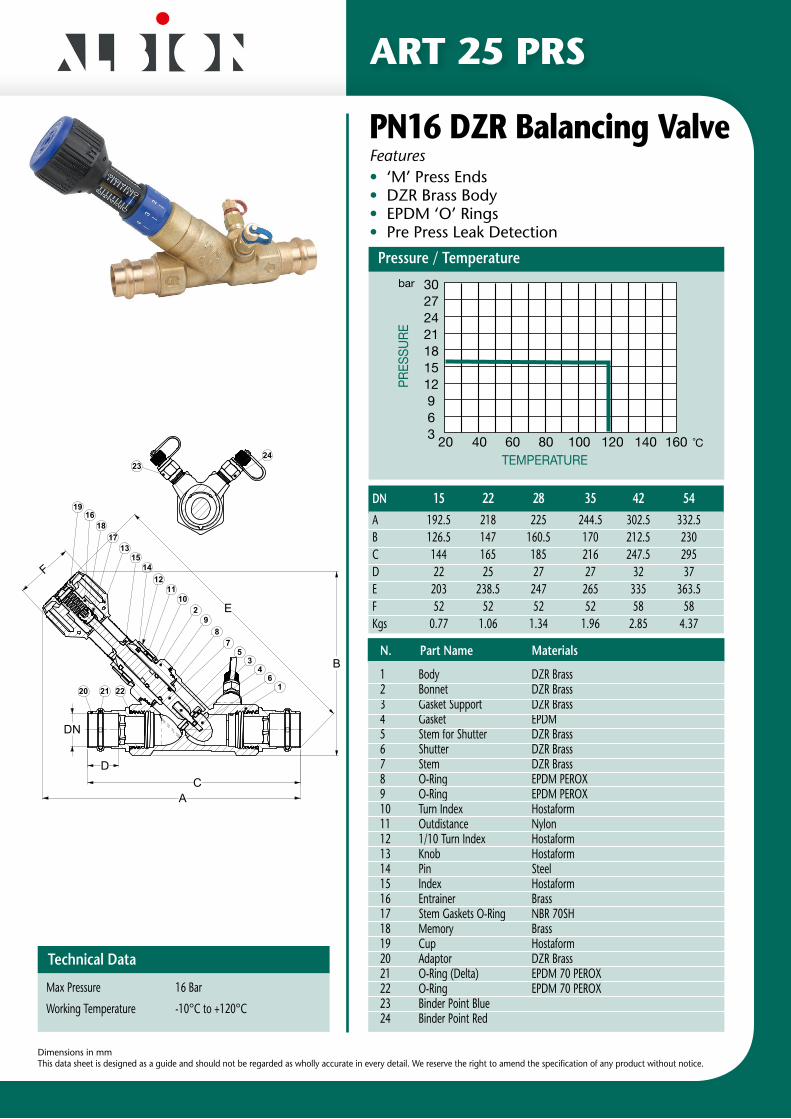
ART 25 PRS
PN16 DZR Balancing ValveFeatures• ‘M’ Press Ends• DZR Brass Body• EPDM ‘O’ Rings• Pre Press Leak Detection
Dimensions in mmThis data sheet is designed as a guide and should not be regarded as wholly accurate in every detail. We reserve the right to amend the specification of any product without notice.
Technical Data
Max Pressure 16 Bar
Working Temperature -10°C to +120°C
DN 15 22 28 35 42 54 A 192.5 218 225 244.5 302.5 332.5 B 126.5 147 160.5 170 212.5 230C 144 165 185 216 247.5 295D 22 25 27 27 32 37E 203 238.5 247 265 335 363.5F 52 52 52 52 58 58Kgs 0.77 1.06 1.34 1.96 2.85 4.37
1 Body DZR Brass 2 Bonnet DZR Brass 3 Gasket Support DZR Brass4 Gasket EPDM5 Stem for Shutter DZR Brass6 Shutter DZR Brass7 Stem DZR Brass8 O-Ring EPDM PEROX 9 O-Ring EPDM PEROX10 Turn Index Hostaform11 Outdistance Nylon12 1/10 Turn Index Hostaform13 Knob Hostaform14 Pin Steel15 Index Hostaform16 Entrainer Brass17 Stem Gaskets O-Ring NBR 70SH18 Memory Brass19 Cup Hostaform20 Adaptor DZR Brass21 O-Ring (Delta) EPDM 70 PEROX22 O-Ring EPDM 70 PEROX23 Binder Point Blue24 Binder Point Red
N. Part Name Materials
UNI EN 22768-mK
S.MAURIZIO D'OPAGLIO (Italy) 28017
DENOMINAZIONE / Part Name
747PRF 28MM
Drawing nr. N° DISEGNO /
Code
SOSTITUISCE IL
PESO (teorico) CODICE/ Checked by
DATA / Date
VISTO /
Scale
Gr.
11/04/2011
1:2.5
DERIVATO DAL /DERIVATI
1,66,3
Pos.
a
b
c
d
e
f
g
. . . .
SCALA /
Changes DATA FIRMA
TOLLERANZE GENERALI STAMPATO:
PROPOSTAMODIFICA /
Drawing by
S.C.DISEG. /
MaterialMATERIALE /
Finishing
29203/0VALV.BILANCIAMENTO C/RAC. PROFILO M
.
.
.
.
.
.
.
.
.
.
.
.
.
.
.
.
.
.
.
.
.
.
.
.
ART 25PRS
TRATTAMENTO /
UNI EN 12420
03-2
011
3DCopyright Cav. Uff. GIACOMO CIMBERIO S.p.A. All rights reserved.©
®FIG.
>0,5 a 6 >6 a 30 >30 a 120 >120 ±0,1 ±0,2 ±0,3 ±0,5TOLLERANZA
QUOTA
A t
erm
ine
di l
eg
ge
ne
è v
ieta
ta la
rip
rod
uzi
on
e o
la c
om
un
ica
zio
ne
a t
erz
i
/\\S
erve
rut\
dati-
ut\3
d_sw
\GRA
FIC
A\C
ATA
LOG
O A
LBIO
N\A
RT 2
5 PR
S\
FORM
ATO
A3
RI
SERV
ATO
E C
ON
FID
ENZI
ALE
TOLLERANZE GENERALI SECONDO LA NORMATIVA:
Pos Q.tà Descrizione Materiale Finitura Disegno Codice
24 1 PRESA DI PRESSIONE BLU CW617N-M 24901/1 460000037000
23 1 PRESA DI PRESSIONE ROSSO CW617N-M 24900/1 460000036900
22 2 O-RING 28.25X2.62 EPDM 70 PEROX 28988 370000077209
21 2 O-RING (DELTA) D.28.3X3 EPDM 70 PEROX 23667/0 370000073209
20 2 ROCCORDO M/PRS CW602N-M . 28974/0 411116315905
19 1 COPERCHIO CON AGGANCIO BLU HOSTAFORM 22529/1 240000003209
18 1 MEMORIA M12 CON SEDE OR CW617N-M 16755/3 360000149009
17 1 GUARN. ASTA O-RING 6.75X1.78 OR106 NBR 70SH -- 12140/1 370000015209
16 1 TRASCINATORE CON FILETTO M12 CW617N-M -- 16753/7 260000060309
15 1 INDICATORE DI POSIZIONE BLU HOSTAFORM 24381/0 240000011409
14 2 SPINA 3X16 UNI 1707 - toll. h8 AVP FE-ZN 16754/3 660000035009
13 1 POMELLO BLU PA66GFN2 16768/5 240000000409
12 1 COLLARINO ESTERNO BLU HOSTAFORM 16758/5 240000002409
11 1 DISTANZIALE NYLON -- 16769/1 270000071509
10 1 COLLARINO DI RIFERIMENTO BLU HOSTAFORM 16757/3 240000002209
9 1 OR 1.78X34.65X38.18 EPDM PEROX -- 28755/0 370000190509
8 2 OR 2.62X9.13 EPDM PEROX -- 28751/0 370000190109
7 1 ASTA OTTURATORE C/OR EPDM PEROX CW602N-M . 28765/0 260000072809
6 1 OTTURATORE CON FILETTO M5 CW602N-M -- 20409/1 260000073209
5 1 PIOLO FILETTATO CW602N-M . 20212/1 260000074109
4 1 GUARNIZIONE OTTURATORE 1" EPDM 70Sh (E 628) . 20411/3 270000071209
3 1 PIATTELLO PORTAGUARNIZIONE 1" CW602N-M . 20410/1 260000074609
2 1 VITONE LAVORATO CW602N-M . 20401/0 220020102505
1 1 CORPO LAVORATO CB 752S -- 20408/5 210038102505
185
31,3
0
37,6
0
11
21
224,2
137
,7
E
E
21 16
35
78
92
1011
1214
15
17
1619
18
4
13
2220
B
F
AC
D
DN
E
2324
Pressure / Temperature
PRES
SURE
3027242118151296 3 20 40 60 80 100 120 140 160 ˚C
TEMPERATURE
bar
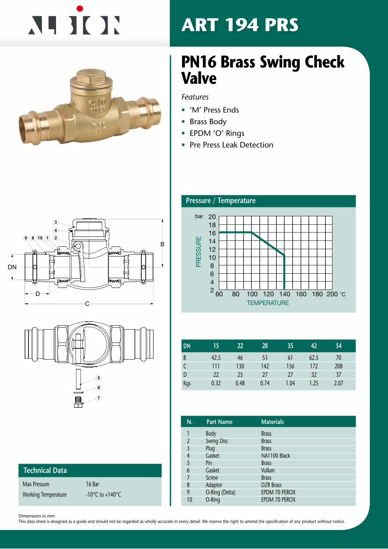
ART 194 PRS
PN16 Brass Swing Check ValveFeatures
• ‘M’ Press Ends• Brass Body• EPDM ‘O’ Rings• Pre Press Leak Detection
Dimensions in mmThis data sheet is designed as a guide and should not be regarded as wholly accurate in every detail. We reserve the right to amend the specification of any product without notice.
Technical Data
Max Pressure 16 Bar
Working Temperature -10°C to +140°C
DN 15 22 28 35 42 54 B 42.5 46 53 61 62.5 70C 111 130 142 156 172 208D 22 25 27 27 32 37Kgs 0.32 0.48 0.74 1.04 1.25 2.07
1 Body Brass 2 Swing Disc Brass 3 Plug Brass4 Gasket NA1100 Black5 Pin Brass6 Gasket Vulkan7 Screw Brass8 Adaptor DZR Brass 9 O-Ring (Delta) EPDM 70 PEROX10 O-Ring EPDM 70 PEROX
N. Part Name Materials
18
4
9 210
3
CD
B
DN
6
7
5
A.P.
VALVE M PRESS FIT ENDS
S.MAURIZIO D'OPAGLIO (Italy) 28017
A t
erm
ine
di l
eg
ge
ne
è v
ieta
ta la
rip
rod
uzi
on
e o
la c
om
un
ica
zio
ne
a t
erz
i 03
-201
1
29156DENOMINAZIONE / Part Name
DISEG.
FORM
ATO
A3
1:1 3D
®FIG.
/
DATA 01/04/2011SCALA
80PRF 28MM
N° DISEGNO / Drawing nr.
RISE
RVA
TO E
CO
NFI
DEN
ZIA
LE
Pressure / TemperaturePR
ESSU
RE
201816141210864 2 60 80 100 120 140 160 180 200 ˚C
TEMPERATURE
bar
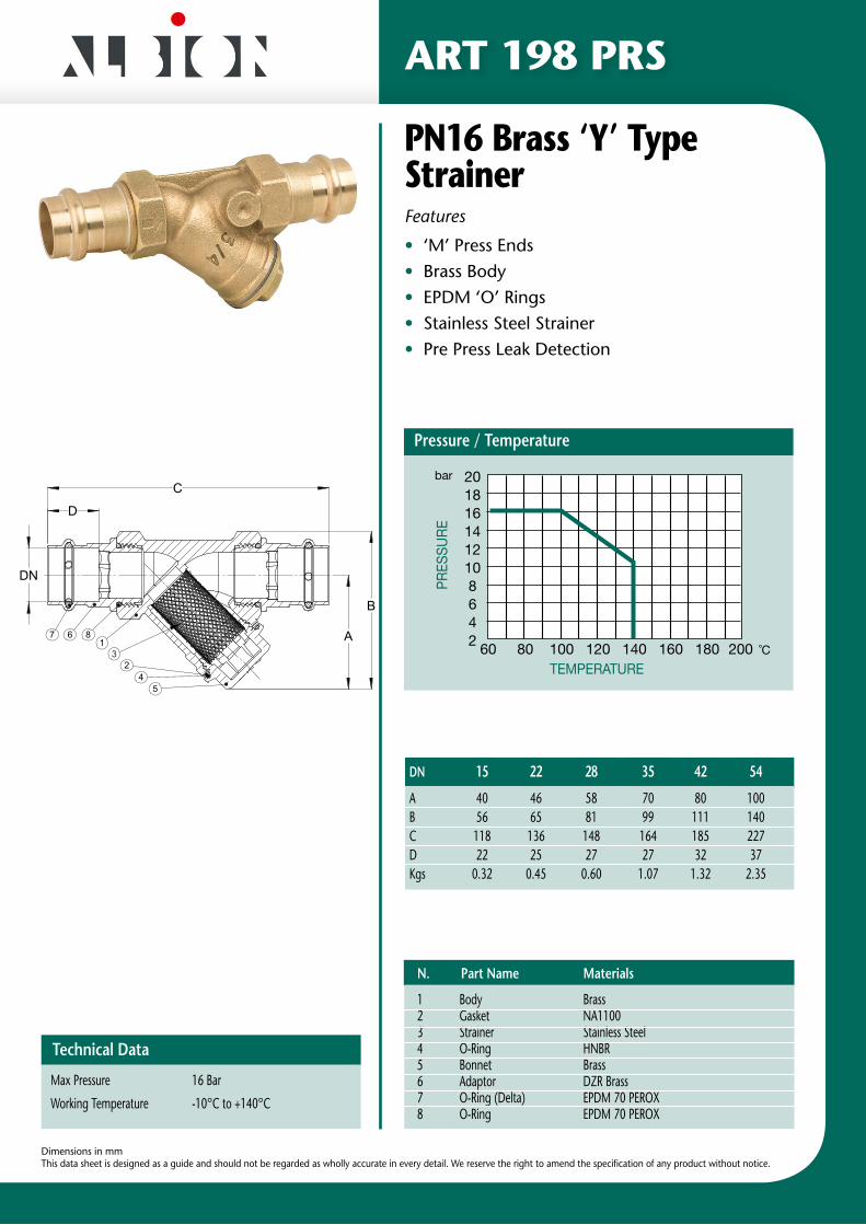
ART 198 PRS
PN16 Brass ‘Y’ Type StrainerFeatures
• ‘M’ Press Ends• Brass Body• EPDM ‘O’ Rings• Stainless Steel Strainer• Pre Press Leak Detection
Dimensions in mmThis data sheet is designed as a guide and should not be regarded as wholly accurate in every detail. We reserve the right to amend the specification of any product without notice.
Technical Data
Max Pressure 16 Bar
Working Temperature -10°C to +140°C
DN 15 22 28 35 42 54 A 40 46 58 70 80 100 B 56 65 81 99 111 140C 118 136 148 164 185 227D 22 25 27 27 32 37Kgs 0.32 0.45 0.60 1.07 1.32 2.35
1 Body Brass 2 Gasket NA11003 Strainer Stainless Steel4 O-Ring HNBR5 Bonnet Brass6 Adaptor DZR Brass 7 O-Ring (Delta) EPDM 70 PEROX8 O-Ring EPDM 70 PEROX
N. Part Name Materials
Pos Q.tà Description Material
8 2 O-RING 28.25X2.62 EPDM 70 PEROX
7 2 O-RING (DELTA) D.28.3X3 EPDM 70 PEROX
6 2 JOINT CW602N-M
5 1 BONNET CW617N-M
4 1 O-RING HNBR
3 1 STRAINER STAINLESS STEEL
2 1 GASKET NA 1100
1 1 BODY CC491K
DATA A.R.DISEG.
/
S.MAURIZIO D'OPAGLIO (Italy) 28017 SCALA 08/09/00
FORM
ATO
A3
03-2
011
1:1
FIG.
DENOMINAZIONE / Part Name
17416/2
A t
erm
ine
di l
eg
ge
ne
è v
ieta
ta la
rip
rod
uzi
on
e o
la c
om
un
ica
zio
ne
a t
erz
i
RACCOGLITORE D'IMPURITA' OBLIQUO
3D74A 1"
N° DISEGNO / Drawing nr.®
RISE
RVA
TO E
CO
NFI
DEN
ZIA
LE
A
A
24
7 6 81
3
5
A
D
C
B
DN
Pressure / TemperaturePR
ESSU
RE
201816141210864 2 60 80 100 120 140 160 180 200 ˚C
TEMPERATURE
bar

ART 55 M & V Fitting Instructions
Dimensions in mmThis data sheet is designed as a guide and should not be regarded as wholly accurate in every detail. We reserve the right to amend the specification of any product without notice.
1. SERVICE RECOMMENDATIONS
Art. 55 M & V ball valves are designed for direct connection to carbon steel and copper pipe work using standard cold pressure press tools. It is suitable for sanitary and heating applications and for drinking water and compressed air networks.
2. FEATURES
• Quick & easy installation using standard press tools;
• lnstallation without the use of solder or soldering torch;
• Patented o-ring design assuring every connection to be pressed & sealed, avoiding installation errors;
• lntegrated, compact design eliminating potential leak points;
• Cost effective and installation time reduction compared to threaded valves;
• Suitable for plumbing and heating applications: pressure class PN16 and temperature rating of 120°C;
• Made of DZR brass “CR” which guarantees added protection against corrosion;
• Available in the range DN15 to DN54.
3. CONNECTION TECHNIQUE
The press connection is made by inserting the pipe into the press fitting as far as the marked insertion depth. The connection is created by pressing, using an approved pressing tool.
During the pressing process a deformation takes place on two sections. The first section creates a permanent connection and provides mechanical pipe locking through the mechanical deformation of the press fitting and the pipe. On the second section the seal ring is deformed in its cross section and through its elastic properties creates the permanently tight joint.
4. SEALING RING PROFILE
Traditional press fitting systems use round sealing rings, which can easily be damaged by careless pipe insertion. Art. 55M & V uses a patented
sealing ring with a lenticular profile which fits the press crimp groove.
This provides the following advantages:
• 20% enlargement of the sealing surface area;
• Reduction of the risk of the sealing ring being pressed out or damaged.
The black EPDM Perox sealing ring in the range 15 to 54 mm is supplied with an additional safety feature that during pressure tests will report a leakage in case of accidentally un-pressed connections.
5. PRESSING TOOLS
Basically, pressing tools consist of pressing machine and pressing jaws or collars/chains. Many of the pressing jaws/collars can generally be used with the pressing machines from one manufacturer. Additionally, many manufacturers of pressing tools have standard jaw connections that pressing jaws from other manufacturers can also be used. All metallic press fitting systems have a pressing profile on the press fittings which matches the one of the pressing jaws/collars. For this reason it is necessary to have the information of the jaws to be used by the manufacturer of the press fittings.
NB: Sizes 15mm to 35mm can be pressed with both ‘M’ and ‘V’ press jaws. Always use the appropriate ‘M’ or ‘V’ press sling to press sizes 42mm and 54mm
Note: in addition, it is important to follow exactly the maintenance and servicing instructions issued by the pressing tool manufacturer.
Dimensions in mmThis data sheet is designed as a guide and should not be regarded as wholly accurate in every detail. We reserve the right to amend the specification of any product without notice.
6. PIPES - CUTTING TO LENGTH AND DEBURRING
Pipes should be cut to length using professional pipe cutters suitable for the material in use.
Alternatively, fine-tooth hacksaws or suitable electric saws may be used. Avoid the use of:
• Tools which may cause tarnishing during the cutting operation;
• Oil-cooled saws;
• Flame cutting or angle grinders.
After cutting, carefully deburr the pipe, both inside and outside to avoid any damage to sealing ring when inserting the pipe into the press fitting. Deburring can be carried out using manual deburring tools which are suitable for the material in use, whilst for larger dimensions suitable electrical pipe deburring tools can be used.
7. MARKING THE INSERTION DEPTH/STRIPPING
Check that the seal rings in the valve are clean, undamaged and placed correctly. Do not oil or grease the seal rings. lnsert pre-prepared pipe end into the valve and push it until the pipes stop, marking the depth of the engagement. Ensure that the insertion depth mark on the pipe corresponds with the press fitting end, otherwise the mechanical stability of the connection cannot be guaranteed. Ensure to have free area around the pipe to operate with the press jaws.
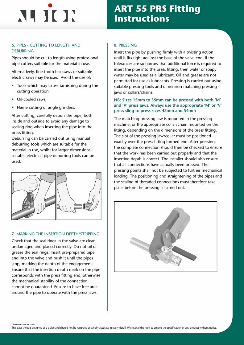
8. PRESSING
lnsert the pipe by pushing firmly with a twisting action until it fits tight against the base of the valve end. lf the tolerances are so narrow that additional force is required to insert the pipe into the press fitting, then water or soapy water may be used as a lubricant. Oil and grease are not permitted for use as lubricants. Pressing is carried out using suitable pressing tools and dimension-matching pressing jaws or collars/chains.
NB: Sizes 15mm to 35mm can be pressed with both ‘M’ and ‘V’ press jaws. Always use the appropriate ‘M’ or ‘V’ press sling to press sizes 42mm and 54mm
The matching pressing jaw is mounted in the pressing machine, or the appropriate collar/chain mounted on the fitting, depending on the dimensions of the press fitting. The slot of the pressing jaw/collar must be positioned exactly over the press fitting formed end. After pressing, the complete connection should then be checked to ensure that the work has been carried out properly and that the insertion depth is correct. The installer should also ensure that all connections have actually been pressed. The pressing points shall not be subjected to further mechanical loading. The positioning and straightening of the pipes and the sealing of threaded connections must therefore take place before the pressing is carried out.
ART 55 PRS Fitting Instructions

Distributor
Certificate No. 1437A
Certificate No. 1437B