Embed Size (px)
Citation preview

Organizational Results Research Report
September 2008 OR09.008
Preservation of Missouri Transportation Infrastructures: Validation of FRP Composite Technology Volume 2 of 5 Life-Cycle Inspection and Monitoring Using Near-Field Microwave Nondestructive Testing Methods
Prepared by Missouri S&T
and Missouri Department of
Transportation

FINAL REPORT RI02-022
Preservation of Missouri Transportation Infrastructures:
Validation of FRP Composite Technology Volume 2
Life-Cycle Inspection and Monitoring Using Near-Field Microwave Nondestructive Testing Methods
Prepared for the Missouri Department of Transportation
Organizational Results
In Cooperation with the National University Transportation Center
by
Center for Infrastructure Engineering Studies Missouri University of Science and Technology
S. Kharkovsky V. Stephen A.C. Ryley
J. T. Robbins R. Zoughi
September 2008 The opinions, findings and conclusions expressed in this report are those of the principal investigator and
the Missouri Department of Transportation. They are not necessarily those of the U.S. Department of
Transportation or the Federal Highway Administration. This report does not constitute a standard, specifi-
cation or regulation.
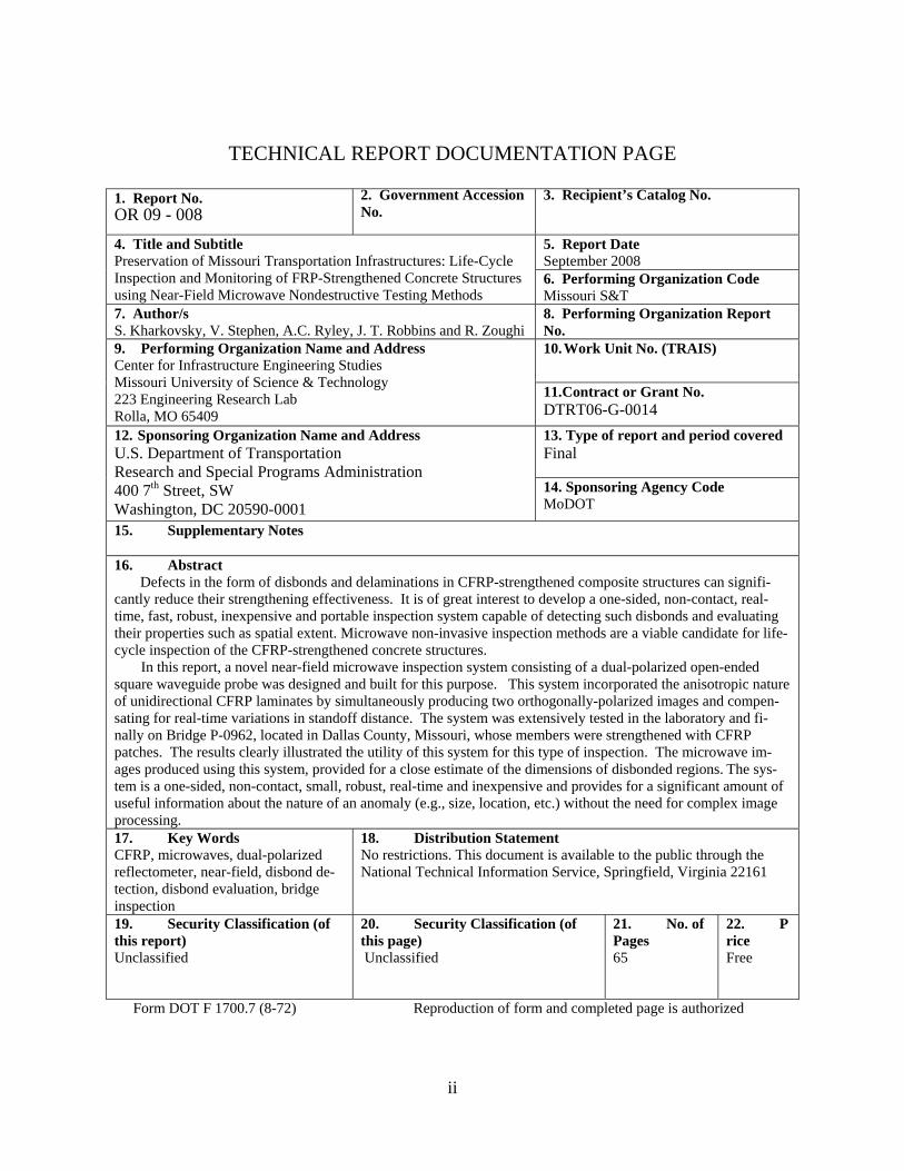
TECHNICAL REPORT DOCUMENTATION PAGE
1. Report No. OR 09 - 008
2. Government Accession No.
3. Recipient’s Catalog No.
5. Report Date September 2008
4. Title and Subtitle Preservation of Missouri Transportation Infrastructures: Life-Cycle Inspection and Monitoring of FRP-Strengthened Concrete Structures using Near-Field Microwave Nondestructive Testing Methods
6. Performing Organization Code Missouri S&T
7. Author/s S. Kharkovsky, V. Stephen, A.C. Ryley, J. T. Robbins and R. Zoughi
8. Performing Organization Report No. 10. Work Unit No. (TRAIS)
9. Performing Organization Name and Address Center for Infrastructure Engineering Studies Missouri University of Science & Technology 223 Engineering Research Lab Rolla, MO 65409
11. Contract or Grant No. DTRT06-G-0014
13. Type of report and period covered Final
12. Sponsoring Organization Name and Address U.S. Department of Transportation Research and Special Programs Administration 400 7th Street, SW Washington, DC 20590-0001
14. Sponsoring Agency Code MoDOT
15. Supplementary Notes 16. Abstract Defects in the form of disbonds and delaminations in CFRP-strengthened composite structures can signifi-cantly reduce their strengthening effectiveness. It is of great interest to develop a one-sided, non-contact, real-time, fast, robust, inexpensive and portable inspection system capable of detecting such disbonds and evaluating their properties such as spatial extent. Microwave non-invasive inspection methods are a viable candidate for life-cycle inspection of the CFRP-strengthened concrete structures. In this report, a novel near-field microwave inspection system consisting of a dual-polarized open-ended square waveguide probe was designed and built for this purpose. This system incorporated the anisotropic nature of unidirectional CFRP laminates by simultaneously producing two orthogonally-polarized images and compen-sating for real-time variations in standoff distance. The system was extensively tested in the laboratory and fi-nally on Bridge P-0962, located in Dallas County, Missouri, whose members were strengthened with CFRP patches. The results clearly illustrated the utility of this system for this type of inspection. The microwave im-ages produced using this system, provided for a close estimate of the dimensions of disbonded regions. The sys-tem is a one-sided, non-contact, small, robust, real-time and inexpensive and provides for a significant amount of useful information about the nature of an anomaly (e.g., size, location, etc.) without the need for complex image processing. 17. Key Words CFRP, microwaves, dual-polarized reflectometer, near-field, disbond de-tection, disbond evaluation, bridge inspection
18. Distribution Statement No restrictions. This document is available to the public through the National Technical Information Service, Springfield, Virginia 22161
19. Security Classification (of this report) Unclassified
20. Security Classification (of this page) Unclassified
21. No. of Pages 65
22. Price Free
Form DOT F 1700.7 (8-72) Reproduction of form and completed page is authorized
ii

TABLE OF CONTENTS
A. INTRODUCTION..................................................................................................... 1 A.1 GENERAL DESCRIPTION ................................................................................................ 1 A.2 OBJECTIVES ...................................................................................................................... 1
B. BACKGROUND ....................................................................................................... 1 B.1 CFRP TECHNOLOGY AND THE ATTRIBUTES OF MICROWAVE TECHNIQUES .. 1 B.2 INFLUENCE OF STANDOFF DISTANCE VARIATION ................................................ 5 B.3 THE BRIDGE AND BONDED CFRP PATCHES.............................................................. 6 B.4 AUTOMATED MICROWAVE IMAGING SYSTEM WITH AN OPEN-ENDED RECTANGULAR WAVEGUIDE PROBE................................................................................ 7
C. NOVEL MICROWAVE INSPECTION SYSTEM WITH A DUAL-POLARIZED OPEN-ENDED WAVEGUIDE PROBE................................................ 9
C.1 REFLECTOMETER DESIGN............................................................................................. 9 C.2 OPTIMIZATION OF THE DUAL-POLARIZED PROBE ............................................... 10 C.3 COMPENSATION OF THE INFLUENCE OF STANDOFF DISTANCE VARIATION 13
D. LABORATORY MEASUREMTENTS................................................................ 15 D.1 CFRP SAMPLES ............................................................................................................... 15 D.2 MICROWAVE IMAGING OF THE CFRP SAMPLES ................................................... 16
E. FIELD MEASUREMENT ..................................................................................... 18 E.1 MICROWAVE IMAGES OF THE CFRP PATCHES AT THE ABUTMENT ................ 19 E.2 MICROWAVE IMAGES OF THE CFRP PATCHES AT THE BENT ............................ 20 E.3 COMPARISON OF THE CFRP PATCHES MICROWAVE IMAGES OBTAINED IN 2005 AND 2006 ........................................................................................................................ 23
SUMMARY ..................................................................................................................... 26
LIST OF OUTCOMES .................................................................................................. 27 PAPERS, PROCEEDINGS AND PRESENTATION .............................................................. 27 MASTERS THESIS.................................................................................................................. 27 PATENT APPLICATION ........................................................................................................ 27
REFERENCES................................................................................................................ 28
APPENDIX A – Schematic of different views of the bridge ....................................... 30
APPENDIX B – Catalog of the microwave images of the CFRP patches obtained in 2004 using a rectangular waveguide probe .................................................................. 35
APPENDIX C – Catalog of the microwave images of the CFRP patches obtained in 2005 using a dual-polarized square waveguide probe................................................. 46
APPENDIX D – Catalog of the microwave images of the CFRP patches obtained in 2006 using a dual-polarized square waveguide probe................................................. 55
iii

LIST OF TABLES Table 1- Power of desired and coupled signals at different ports..................................... 12
LIST OF FIGURES
Figure 1: Microwave and millimeter wave frequency ranges and associated wavelengths (not to-scale). .............................................................................................................. 2
Figure 2: The schematic of a layered CFRP reinforced concrete structure irradiated by an open-ended waveguide probe ..................................................................................... 3
Figure 3 - Typical geometry of a CFRP-strengthened concrete structure being inspected by an open-ended waveguide probe showing surface roughness, disbonds and standoff distance variations (not-to-scale). ................................................................. 5
Figure 4 - Picture of bent-A of the bridge P-0962 with FRP bonded patches before they were painted. ............................................................................................................... 7
Figure 5 - Picture of the automated scanner. ...................................................................... 8 Figure 6 - Schematic of the computer-controlled 2D scanning mechanism and the
microwave reflectometer CFRP concrete member. .................................................... 9 Figure 7 - Schematic of the inspection system with the dual-polarized microwave
reflectometer. ............................................................................................................ 10 Figure 8 - Schematic of a square waveguide dual-polarized probe and microwave circuits.
................................................................................................................................... 11 Figure 9 - Picture of a packaged reflectometer with a square waveguide dual-polarized
probe and microwave circuits: (a) sealed and (b) with interior exposed. ................. 12 Figure 10 - a) Dependency of the measured output voltage of reflected signals at the
parallel and perpendicular polarization ports on the standoff distance (vertical dash-dot lines represent the range of standoff distance corresponding to the linear regions) and (b) original and transformed linear region of the dependency for parallel polarization. .............................................................................................................. 14
Figure 11 - Picture of CFRP cement-based sample (a) #1 an (b) #2. ............................... 15 Figure 12 - A picture of the 2D scanning mechanism and the microwave reflectometer
testing a tilted CFRP-mortar sample in the laboratory. ............................................ 16 Figure 13 - (a) Schematic of the tilted CFRP mortar sample with disbonded region and
the microwave images of the disbonded region (b) at perpendicular polarization, (c) at parallel polarization, and (d) compensated image (dimensions in mm). .............. 17
Figure 14 - (a) Microwave compensated image of the disbond generated using the dual-polarized reflectometer and (b) boundary of the disbond at the 3-dB level (dashed line shows the boundary of the disbond obtained by tapping method, (dimensions in mm)).......................................................................................................................... 18
Figure 15 - A picture of the 2D scanning mechanism and the microwave reflectometer testing CFRP patch bonded to the abutment of a bridge. ......................................... 19
Figure 16 - Microwave images of a CFRP patch at the abutment (dimensions in mm): (a) at perpendicular polarization, (b) at parallel polarization, and (c) compensated image (detected disbonds are marked by red arrows). ........................................................ 20
iv
Figure 17 - A picture of the bent with CFRP patches and 2D scanning mechanism with the microwave reflectometer testing CFRP patch #1. .............................................. 20
Figure 18 - The dual-polarized microwave reflectometer attached to a scanning platform while inspecting a CFRP patch #1 bonded to the bent of a bridge. .......................... 21
Figure 19 - Microwave images of the portion (270 mm by 330 mm) of the CFRP patch at: (a) perpendicular polarization, (b) parallel polarization, and (c) compensated image (detected disbonds are marked by red arrows). ........................................................ 22
Figure 20 - A picture of the 2D scanning mechanism and the microwave reflectometer testing CFRP patch bonded to the side wall of the bent. .......................................... 23
Figure 21 - Microwave images of a CFRP patch at the bent: (a) at perpendicular polarization, (b) at parallel polarization, and (c) compensated image (detected disbonds are marked by red arrows). ........................................................................ 23
Figure 22 - Microwave images of a CFRP patch #1 at the bent: (a) at perpendicular polarization, (b) at parallel polarization, and (c) compensated image obtained in (left column) October 14, 2005 and (right column) in May 26, 2006. Red arrows show disbonds. ................................................................................................................... 24
Figure 23 - Microwave images of a CFRP patch #2 at the bent: (a) at perpendicular polarization, (b) at parallel polarization, and (c) compensated image obtained in (left column) October 14, 2005 and (right column) in May 26, 2006. Red arrows show disbonds. ................................................................................................................... 25
v

A. INTRODUCTION
A.1 General Description In the following report, the development, design and testing of a novel near-field mi-
crowave inspection system employing a dual-polarized reflectometer at X-band (8.2 – 12.4 GHz) for detecting defects such as disbond between CFRP laminates and strength-ened structures are summarized. Several measurements using this system were conducted on Bridge P-0962, located in Dallas County, MO, whose members were strengthened with carbon fiber reinforced polymer (CFRP) laminates.
A.2 Objectives The objective of this endeavor has been to produce a unique microwave inspection
concept and validated method for detecting disbonds between CFRP laminates and strengthened concrete structures.
B. BACKGROUND
B.1 CFRP Technology and the Attributes of Microwave Tech-niques
CFRP composites are increasingly being used for rehabilitating existing structures as well as newly constructed bridges [1-3]. CFRP composites are externally bonded to con-crete members to provide additional flexural, shear or confining reinforcement since they are strong, lightweight and not susceptible to corrosion. The use of CFRP for strengthen-ing of structural members, such as bridge girders and bents, is very attractive since this process is inexpensive, rapid and does not disrupt traffic flow. Nevertheless, validation of the retrofit quality, at the time of installation and during service, is extremely impor-tant. If the CFRP laminate becomes disbonded from the structure, and depending on the relative size of the disbonded region, the effectiveness of the retrofit may be significantly diminished. Disbonds between a CFRP laminate and concrete may occur due to a variety of reasons including improper application of the laminate, presence of moisture near the concrete surface, impact damage, etc. Currently, the most prominent on-site methods for detecting disbonds and other defects or anomalies such as cracks, impact damages, fiber breakages, and fiber misalignment are visual inspection and tap testing. However, some disbonds may be undetectable by visual inspection and/or may be small, but they may still cause significant degradation on the strengthening effectiveness of the laminate. Thus, it is of great interest to develop a one-sided, non-contact, real-time, fast, robust, inexpensive and portable inspection system capable of detecting such disbonds and eva-luating their properties such as spatial extent. Several NDT&E techniques have been con-
1

sidered and attempted for inspecting CFRP composites for the presence of disbonds, con-crete damage and fiber misalignment, including microwave techniques [14-16].
Electromagnetic signals at microwave frequencies are electromagnetic waves that are well suited for inspecting dielectric materials and in particular composite structures that are increasingly being used in many critical applications [17]. The well-established mi-crowave frequency spectrum spans a range of ~300 MHz-30 GHz with the corresponding to wavelength ranges of 1000 mm-10 mm [18]. Figure 1 shows the frequency and wave-lengths associated with microwaves.
3x10⁸ 3x10¹⁰ 3x10¹¹ Hz
1000 10 1 mm
Frequency
Wavelength
Microwaves Millimeter Waves
Figure 1 - Microwave and millimeter wave frequency ranges and associated wavelengths (not to-scale).
Microwave signals can penetrate inside generally lossy dielectric materials and inter-
act with their inner structure. Microwave signals also partially reflect at dissimilar boundaries in a layered composite and this information can be used to detect and evaluate the presence of a disbond [17]. Near-field microwave non-invasive techniques, utilizing open-ended rectangular waveguide probes, have demonstrated the ability to detect defects such as disbonds, delaminations in CFRP-strengthened cement-based structures using relatively simple microwave reflectometers [13-17]. Unlike ultrasonic testing methods, near-field microwave methods do not require contact between the microwave probe and the material under test. When a CFRP laminate is adhered to a concrete structure in the presence or absence of disbond, a layered composite geometry is produced. Figure 2 shows the geometry (not-to-scale) of a CFRP reinforced concrete structure, when there is a disbonded region between the CFRP laminate and the concrete substrate, and an open-ended waveguide probe. The distance between the open-ended probe and the material under test is referred to as the standoff distance (or liftoff). The utility of near-field mi-crowave NDT&E techniques, using open-ended waveguide probes, for detecting dis-bonds and delaminations in layered composite structures has been demonstrated for over a decade [17]. Testing and evaluation of this type of complex composites has been the focus of extensive theoretical and experimental investigations during this period by the investigators at the Applied Microwave Nondestructive Testing Laboratory (amntl) at the
2

UMR [13-17]. When a microwave signal, radiated by the open-ended waveguide probe, interacts with a layered structure, it partially reflects at each boundary and partially transmits through the boundary. The properties of the reflected signal (magnitude and phase) that is picked up by the probe depend on the dielectric properties of layers and their thickness. Microwave signals do not penetrate inside of highly conducting materials such as metals and high-density carbon-loaded composites.
CFRP Laminate (Layer 2)
Open-Ended Wa-veguide Probe
Standoff Distance
Air (Layer 3) (Disbond) Concrete (Layer 4)
Air (Layer 1)
Figure 2 - The schematic of a layered CFRP reinforced concrete structure irradiated by an open-ended waveguide probe.
Carbon is highly conductive at microwave frequencies. However, laminates made of
unidirectionally aligned carbon fibers interact differently with microwave signals as a function of the relative orientation of the fibers and the microwave signal polarization defined as the orientation of the electric field vector [18]. For strengthening purposes, CFRP laminates are commonly unidirectional in order to provide additional strength in a particular direction. The open-ended waveguide probes widely used in microwave NDT&E techniques [17] produce linearly polarized microwave signals. Consequently, when using a unidirectional CFRP laminate, the microwave signals easily penetrate through the laminate when the fiber directions and the signal polarization are orthogonal to one another (perpendicular polarization). In this case, the microwave signal partially reflects at each boundary of the layered structure as shown in Figure 2, and partially
3

transmits through the boundary. The total reflected signal that is picked up by the probe is the coherent addition of all reflected waves from all boundaries. At each boundary the magnitude and phase of the reflected signal is directly proportional to the dielectric con-stant (property) contrast between the two materials producing the boundary. Thus, it is clear that the total reflected signal from areas with and without disbond is different. However, when the fiber directions and the signal polarization are parallel to one another (parallel polarization), the signal reflects off of the laminate, resulting in very little signal penetration. In both cases reflected signal is used to generate two-dimensional (2D) im-ages of testing area. The perpendicular polarization case is well-suited for detecting and evaluating disbonds and concrete damages hidden by CFRP, whereas the parallel polari-zation case provides information about surface roughness, fiber breakage in the CFRP, standoff distance changing during the inspection, etc. [13-16]. Moreover, both cases may be used in conjunction with one another to obtain an image, which provides information about the internal structure (under CFRP) and disbonds, while removing the undesired influence of standoff distance (or surface roughness) variations from the measurements.
Microwave near-field NDT&E techniques, utilizing open-ended waveguide probes, reflectometers and imaging techniques, have demonstrated the ability to detect defects such as disbonds, delaminations in composite structures and evaluate their various prop-erties. They offer many advantages when inspecting disbond and delamination in CFRP laminates bonded to concrete substrates [17], namely:
1) these near-field techniques are real-time, fast, non-contact and one-sided, 2) these techniques provide for a high level of measurement sensitivity (i.e., detect-
ing thin disbonds) while providing for a relatively fine spatial resolution, 3) microwave systems capable of producing robust inspection can be manufactured
to be small, handheld, battery operated, and relatively inexpensive, readily expanding their realm of operation and utility,
4) these systems are capable of producing local information for spot checking or provide line scans or 2D images (i.e., raster scans) of a suspect region,
5) these images may be stored electronically and easily accessed at a later time to compare with a new set of measurements/images to monitor changes in a given region,
6) the same system used for detecting a disbond can be used to evaluate the integrity of an epoxy-injected repair, as well as to detect and evaluate other defects such as impact damages, fiber breakages, fiber misalignment, rendering this technique extremely versa-tile,
7) there is no need for operator expertise, in the field of microwave engineering, when using these systems,
8) these systems require low microwave power (usually between 1-10 mW) and are therefore safe to use (microwave signals are non-ionizing unlike X-rays), and
9) these systems are not sources of electromagnetic interference, since they operate at very specific frequencies and are low powered and are not affected by other high fre-quency systems, which may be operating nearby.
4

The microwave near-field techniques using linearly polarized signals were found to produce encouraging laboratory results which have led to further investigation and im-provement of these techniques, and in-field inspection and monitoring of CFRP rein-forced concrete bridge members [13 – 14].
B.2 Influence of Standoff Distance Variation From a practical point of view the standoff distance is an attractive feature (i.e., non-
contact measurements). However, in practice while scanning a sample, the standoff dis-tance may change due to a local relative tilt between the surface of sample under test and the probe, undesired shaking/movement of the sample or the probe, the complex shape of the structure and/or surface roughness. CFRP-strengthened concrete structures may have complex shape, surface roughness, along with various defects such as disbonds and im-pact damages. Figure 3 shows the geometry of a typical CFRP-strengthened concrete structure being inspected by an open-ended waveguide probe which scans the structure in a 2D fashion creating a raster image. Changes in standoff distance can significantly influ-ence the properties of the reflected microwave signal from the sample under
Concrete
Open-Ended Waveguide Probe
Surface RoughnessThin
Disbond
Surface Roughness/Bulging
Disbond
Standoff Distance
CFRP
Figure 3 - Typical geometry of a CFRP-strengthened concrete structure being inspected by an open-ended waveguide probe showing surface roughness, disbonds and standoff
distance variations (not-to-scale).
test [17, 19]. Consequently, when microwave images of a sample are produced indica-tions of subtle anomalies such as disbonds and delaminations may be easily masked from indications associated with standoff distance change. There are several techniques that may be used to reduce the undesired influence of standoff distance variation. One method involves the use of a mechanical (i.e. roller) system that can keep the standoff distance
5

fairly constant during the scan. However, this method is ineffective when sample under test possess local surface roughness/bulging that may be smaller in spatial extent than the inspection area of the open-ended probe. Moreover, this is no longer a non-contact meas-urement. Another method involves measuring the standoff distance variation during a scan and then removing its undesired influence by post processing (e.g., subtracting the effect of standoff distance variation from the reflected signal). One way to accomplish this would be to have a spring-loaded potentiometer that is in contact with the surface of the sample and during the scan a voltage proportional to the potentiometer resistance is generated indicating the variations in standoff distance during a scan. Such a system was recently developed and used for inspecting thick glass fiber reinforced epoxy (GFRP) composites [19]. There are two basic disadvantages associated with this system, namely, i) the po-tentiometer is in contact with the surface of the sample (which makes the measurements not completely non-contact and ii) the potentiometer is attached to the side of the open-ended waveguide probe and therefore does not measure the standoff distance exactly un-der the probe. When using this system in conjunction with GFRP composites, this sys-tem performed quite well [19]. As discussed in subsection B.1, unidirectional CFRP la-minates are anisotropic and this feature lends itself extremely useful for removal of the influence of standoff distance from an image or measurement. Moreover, as will be shown in the section C, this feature allows for simultaneous removal of the influence of standoff distance.
B.3 The Bridge and Bonded CFRP Patches The NDT&E investigation was concentrated on one of the existing bridges, P-0962
(Golden Bridge), located in Dallas County, Missouri, which was strengthened using ma-nual lay-up CFRP laminates technology. This investigation covers the aspect of detection of disbonds between CFRP laminates and bridge concrete members. For this purpose, several 0.6 m by 0.6 m (2 ft by 2 ft) CFRP patches were bonded (using epoxy adhesive) to the abutment and the bent of the bridge. For instance, Figure 4 shows a picture of one of the bents with bonded fiber reinforced polymer (FRP) patches. Schematics of different views of the bridge with all FRP patches can be found in Appendix A. It can be seen from these schematics that CFRP patches are located near the ends and on the side of the bent.
A number of artificial disbonds (intentional defects) were manufactured by injecting
air between CFRP patches and concrete members at non-critical locations of the bonded CFRP patches when the epoxy adhesive was in its fresh state. The size and thickness (i.e. severity) of the disbonds were also varied using this process. The bonded CFRP patches in the abutment were used as reference since this part of the bridge is not usually streng-thened by CFRP laminates. Moreover, the disbonds produced in the bent were thinner than the disbonds produced in the abutment. In addition, the bent with bonded CFRP patches were painted (Figure 4 shows the bent before it was painted).
6
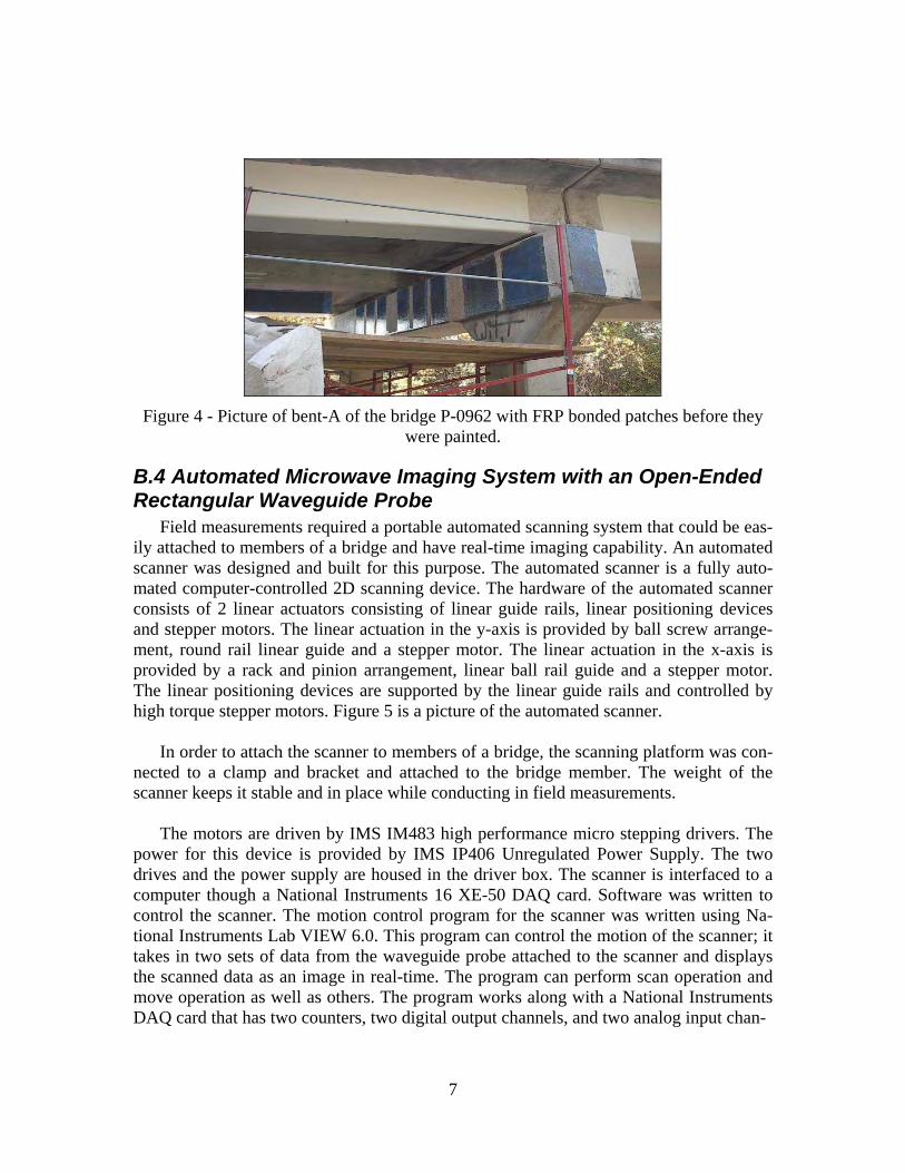
Figure 4 - Picture of bent-A of the bridge P-0962 with FRP bonded patches before they
were painted.
B.4 Automated Microwave Imaging System with an Open-Ended Rectangular Waveguide Probe
Field measurements required a portable automated scanning system that could be eas-ily attached to members of a bridge and have real-time imaging capability. An automated scanner was designed and built for this purpose. The automated scanner is a fully auto-mated computer-controlled 2D scanning device. The hardware of the automated scanner consists of 2 linear actuators consisting of linear guide rails, linear positioning devices and stepper motors. The linear actuation in the y-axis is provided by ball screw arrange-ment, round rail linear guide and a stepper motor. The linear actuation in the x-axis is provided by a rack and pinion arrangement, linear ball rail guide and a stepper motor. The linear positioning devices are supported by the linear guide rails and controlled by high torque stepper motors. Figure 5 is a picture of the automated scanner.
In order to attach the scanner to members of a bridge, the scanning platform was con-
nected to a clamp and bracket and attached to the bridge member. The weight of the scanner keeps it stable and in place while conducting in field measurements.
The motors are driven by IMS IM483 high performance micro stepping drivers. The
power for this device is provided by IMS IP406 Unregulated Power Supply. The two drives and the power supply are housed in the driver box. The scanner is interfaced to a computer though a National Instruments 16 XE-50 DAQ card. Software was written to control the scanner. The motion control program for the scanner was written using Na-tional Instruments Lab VIEW 6.0. This program can control the motion of the scanner; it takes in two sets of data from the waveguide probe attached to the scanner and displays the scanned data as an image in real-time. The program can perform scan operation and move operation as well as others. The program works along with a National Instruments DAQ card that has two counters, two digital output channels, and two analog input chan-
7
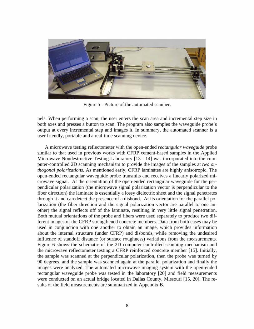
Figure 5 - Picture of the automated scanner.
nels. When performing a scan, the user enters the scan area and incremental step size in both axes and presses a button to scan. The program also samples the waveguide probe’s output at every incremental step and images it. In summary, the automated scanner is a user friendly, portable and a real-time scanning device.
A microwave testing reflectometer with the open-ended rectangular waveguide probe similar to that used in previous works with CFRP cement-based samples in the Applied Microwave Nondestructive Testing Laboratory [13 - 14] was incorporated into the com-puter-controlled 2D scanning mechanism to provide the images of the samples at two or-thogonal polarizations. As mentioned early, CFRP laminates are highly anisotropic. The open-ended rectangular waveguide probe transmits and receives a linearly polarized mi-crowave signal. At the orientation of the open-ended rectangular waveguide for the per-pendicular polarization (the microwave signal polarization vector is perpendicular to the fiber direction) the laminate is essentially a lossy dielectric sheet and the signal penetrates through it and can detect the presence of a disbond. At its orientation for the parallel po-larization (the fiber direction and the signal polarization vector are parallel to one an-other) the signal reflects off of the laminate, resulting in very little signal penetration. Both mutual orientations of the probe and fibers were used separately to produce two dif-ferent images of the CFRP strengthened concrete members. Data from both cases may be used in conjunction with one another to obtain an image, which provides information about the internal structure (under CFRP) and disbonds, while removing the undesired influence of standoff distance (or surface roughness) variations from the measurements. Figure 6 shows the schematic of the 2D computer-controlled scanning mechanism and the microwave reflectometer testing a CFRP reinforced concrete member [15]. Initially, the sample was scanned at the perpendicular polarization, then the probe was turned by 90 degrees, and the sample was scanned again at the parallel polarization and finally the images were analyzed. The automated microwave imaging system with the open-ended rectangular waveguide probe was tested in the laboratory [20] and field measurements were conducted on an actual bridge located in Dallas County, Missouri [15, 20]. The re-sults of the field measurements are summarized in Appendix B.
8

Laptop
Oscillator
Microwave ProbeScanner
Detector
Driver
Figure 6 - Schematic of the computer-controlled 2D scanning mechanism and the micro-wave reflectometer CFRP concrete member.
. The analysis of these results pointed out that the system with the open-ended waveguide probe provides the images of the CFRP laminates including disbonds, surface roughness and defects, with high resolution. However, there are disadvantages of this system such as relatively long time of measurement and low accuracy of disbond evaluation (sizing) due to a difference between irradiated areas for scans at perpendicular and parallel polari-zations. To overcome these problems, a novel microwave inspection system with a dual-polarized open-ended waveguide probe was proposed.
C. NOVEL MICROWAVE INSPECTION SYSTEM WITH A DUAL-POLARIZED OPEN-ENDED WAVEGUIDE
PROBE
C.1 Reflectometer Design The dual-polarized reflectometer system was designed and constructed at X-band
(8.2–12.4 GHz) [16]. This frequency range was found to be optimal for inspection of CFRP-strengthened structures [13-15]. Figure 7 shows the schematic of the reflectometer which consists of a computer-controlled 2D scanning mechanism, two microwave cir-cuits incorporated into a dual-polarized square waveguide probe, and a conditioning cir-cuit (real-time signal processing section) which provides for automatic removal of stand-off distance variation. The open-ended square waveguide probe was chosen for the re-flectometer since it may simultaneously support two orthogonally polarized dominant TE10 mode microwave signals. In addition, these two signals irradiate the same area on the CFRP sample and receive reflected signals from the same area as well. This is impor-tant since standoff distance variation removal will now correspond to the same exact
9
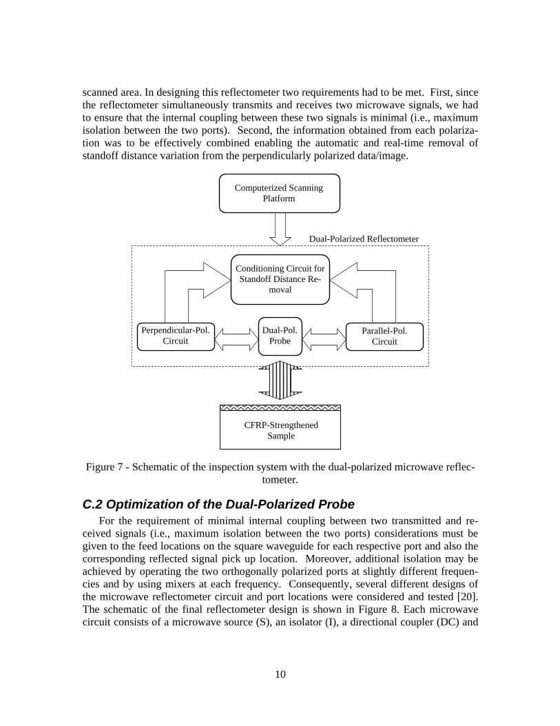
scanned area. In designing this reflectometer two requirements had to be met. First, since the reflectometer simultaneously transmits and receives two microwave signals, we had to ensure that the internal coupling between these two signals is minimal (i.e., maximum isolation between the two ports). Second, the information obtained from each polariza-tion was to be effectively combined enabling the automatic and real-time removal of standoff distance variation from the perpendicularly polarized data/image.
Computerized ScanningPlatform
Dual-Polarized Reflectometer
Conditioning Circuit forStandoff Distance Re-
moval
Parallel-Pol. Circuit
Perpendicular-Pol. Circuit
Dual-Pol.Probe
CFRP-StrengthenedSample
Figure 7 - Schematic of the inspection system with the dual-polarized microwave reflec-tometer.
C.2 Optimization of the Dual-Polarized Probe For the requirement of minimal internal coupling between two transmitted and re-
ceived signals (i.e., maximum isolation between the two ports) considerations must be given to the feed locations on the square waveguide for each respective port and also the corresponding reflected signal pick up location. Moreover, additional isolation may be achieved by operating the two orthogonally polarized ports at slightly different frequen-cies and by using mixers at each frequency. Consequently, several different designs of the microwave reflectometer circuit and port locations were considered and tested [20]. The schematic of the final reflectometer design is shown in Figure 8. Each microwave circuit consists of a microwave source (S), an isolator (I), a directional coupler (DC) and
10

a mixer (M). There are two sets of transmitting and receiving ports (corresponding to the two polarizations) placed at orthogonal sides of the square waveguide probe. For each polarization, portions of the transmitted and reflected signals are combined in the mixer to produce DC output voltages primarily proportional to their respective phase difference.
Output DC voltage 2
S1
I1
M1
S2
M2
Input DC voltage
Output DC voltage 1
DC1
I2 DC2
Figure 8 - Schematic of a square waveguide dual-polarized probe and microwave circuits.
The relative locations of the feed and pick up ports, and the length of the feed ele-
ments inside the waveguide were optimized to provide minimum unwanted coupling and increased internal isolation between the two ports. This was done in conjunction with the fact that each port operated at a different frequency since, as mentioned earlier, frequency diversity can provide for additional isolation between the two orthogonally polarized ports [20]. To evaluate the coupling between the two ports, the signal power at one port was measured in the presence, and absence, of signal at the other port. The results of this measurement showed that when the two ports are operating at the same frequency, the power associated with the unwanted coupled signal may be relatively large (> -10 dBm), while when the two ports are operating at different frequencies the unwanted coupled power level was less than -30 dBm. For example, the results of these measurements at four different frequencies are shown in Table 1. As a result, two operating frequencies, 9.6 GHz for parallel and 11.6 GHz for perpendicular polarization, were selected for the reflectometer.
Figure 9 shows the picture of a packaged reflectometer which consists of a square
waveguide dual-polarized probe and microwave circuits.
11

Table 1- Power of desired and coupled signals at different ports
Frequency, GHz Power of desired signal, dBm Power of coupled signal, dBm Port 1 Port 2 Port 1 Port 2 Port 1 Port 2 12.2 -16.6 -29.9 11.6 -9.0 -40
8.6 -16.8 -24 9.6 -9.6 -31.5
(a)
(b)
Figure 9 - Picture of a packaged reflectometer with a square waveguide dual-polarized probe and microwave circuits: (a) sealed and (b) with interior exposed.
12

C.3 Compensation of the Influence of Standoff Distance Varia-tion
The second important design criterion was to use the output signal from the parallel polarization to achieve effective removal of the influence of standoff distance variations from the perpendicular polarization data/image. For this purpose, the dependency of the output voltages, corresponding to the two orthogonally polarized reflected signals, on standoff distance were measured and analyzed for several CFRP-strengthened cement-based structures leading to the design of the compensation circuit. Figure 10a shows the typical dependency of the measured output voltages on standoff distance for an irradiated area of CFRP-concrete sample without disbond. As expected and can be seen from Figure 10a, the output voltages do not follow a monotonic change as a function of increasing standoff distance [20]. However, the results show that for the standoff distance range of 7 mm - 11 mm both curves are fairly linear. This is important since in this range the par-allel polarization output voltage can be used to determine the value of standoff distance and its variation. Subsequently, when operating in this region the influence of standoff distance variation can be measured and removed from the perpendicular polarization da-ta/image using a relatively simple compensation circuit. The compensation circuit first transforms the linear region of the curve for the parallel polarization data to match the corresponding linear region of the curve for the perpendicular polarization, as shown in Figure 10a. This transformation is performed using a polynomial equation which for the linear region in Figure 10b is:
Vtr = 0.0045V3
par + 0.3786V2par + 13.6093Vpar, (1)
where Vtr and Vpar are transformed voltage and voltage corresponding to signal with par-allel polarization, respectively. The compensated voltage Vcomp is the difference between the voltage corresponding to the signal of perpendicular polarization Vperp and Vtr:
Vcomp = Vperp – Vtr . (2)
Subsequently, the transformed data is subtracted from the data corresponding to the
perpendicular polarization and in doing so removes the contribution of the reflected sig-nal from the surface of the sample (i.e., change in standoff distance). Then, once a scan is conducted at a standoff distance within the range of 7 mm - 11 mm (standoff distance of about 8 mm was used here), the influence of the standoff distance variation from the data corresponding to the perpendicular polarization will be automatically removed and a compensated image of the sample which primarily indicates the presence of a disbond is generated. As a result, the system simultaneously generates three images of the defect in real-time, namely; two at orthogonal polarizations and one (compensated image) after the influence of the undesired standoff distance variation is removed and only information about the disbonds is preserved. Consequently, this novel inspection system is capable of i) detection and evaluation of different types of defects in CFRP-reinforced structures, and ii) reduces the time required for data/image post processing due to an automatic re-
13

moval of undesired yet invariably present influence of standoff distance variation in addi-tion to performing the scan only once (unlike the rectangular waveguide case where two separate scans were needed).
-250-200-150-100-50
050
100150200250300
0 2 4 6 8 10 12 14 16 18 20
Standoff distance (mm)
Volta
ge (m
V)
parallel polarizationperp polarization
(a)
-150
-100
-50
0
50
100
150
200
250
7 8 9 10
Standoff distance (mm)
Volta
ge (m
V)
Original
Transformed
11
(b)
Figure 10 - a) Dependency of the measured output voltage of reflected signals at the par-allel and perpendicular polarization ports on the standoff distance (vertical dash-dot lines represent the range of standoff distance corresponding to the linear regions) and (b) orig-
inal and transformed linear region of the dependency for parallel polarization.
14
D. LABORATORY MEASUREMTENTS
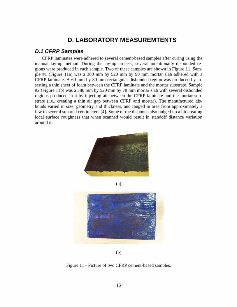
D.1 CFRP Samples CFRP laminates were adhered to several cement-based samples after curing using the
manual lay-up method. During the lay-up process, several intentionally disbonded re-gions were produced in each sample. Two of these samples are shown in Figure 11. Sam-ple #1 (Figure 11a) was a 380 mm by 520 mm by 90 mm mortar slab adhered with a CFRP laminate. A 60 mm by 80 mm rectangular disbonded region was produced by in-serting a thin sheet of foam between the CFRP laminate and the mortar substrate. Sample #2 (Figure 11b) was a 380 mm by 520 mm by 78 mm mortar slab with several disbonded regions produced in it by injecting air between the CFRP laminate and the mortar sub-strate (i.e., creating a thin air gap between CFRP and mortar). The manufactured dis-bonds varied in size, geometry and thickness, and ranged in area from approximately a few to several squared centimeters [4]. Some of the disbonds also bulged up a bit creating local surface roughness that when scanned would result in standoff distance variation around it.
(a)
(b)
Figure 11 - Picture of two CFRP cement-based samples.
15

D.2 Microwave Imaging of the CFRP Samples Figure 12 shows a picture of the 2D scanning mechanism and the microwave reflec-
tometer with the dual-polarized square waveguide probe inspecting sample #1. To better demonstrate the utility of this system, the sample was intentionally tilted, with respect to the probe scan plane, to produce a relatively severe standoff distance variation over the scan area.
Microwave reflectometer
Scanning mechanism
CFRP sample
Figure 12 - A picture of the 2D scanning mechanism and the microwave reflectometer testing a tilted CFRP-mortar sample in the laboratory.
Figure 13a shows the schematic of the tilted sample #1 being tested by the square
waveguide probe. Subsequently, an area of 140 mm by 140 mm which included the dis-bonded region was raster scanned and its image was produced by recording the raster output voltages from the two orthogonally polarized ports, normalizing each data matrix with respect to its highest voltage value and producing a grey scale image. Figures 13b-d show the corresponding microwave images of the scanned area. Dimensions in these im-ages and all subsequent images are in millimeters. As expected, the disbonded region is clearly visible in the image for perpendicular polarization (Fig. 13b). However, the indi-cation of the disbonded region is also visible in the image for parallel polarization (Fig. 13c). The image in Fig. 13c is an indication of the slight surface bulging due to the pres-ence on the thin foam insert representing the disbond. Both images show variations with-in the disbonded region due to its non-uniform thickness (in one case representing dis-bond thickness variation and in the other standoff distance variations, respectively). Moreover, both images show a gradual intensity change from left to right representing the intentionally induced standoff distance change over the scanned area due to the sample
16

Tilted Cement-Based Sample
CFRPDisbondStandoff Distance
Reflectometer
(a)
(b) (c)
(d)
Figure 13 - (a) Schematic of the tilted CFRP mortar sample with disbonded region and the microwave images of the disbonded region (b) at perpendicular polarization, (c) at
parallel polarization, and (d) compensated image (dimensions in mm).
tilt. Figure 13d shows the compensated image in which the effect of standoff distance variation is completely removed from the perpendicularly-polarized image (Fig. 13b). Figure 13d clearly shows the disbonded region and indicates the fact that its thickness is not uniform. Additionally and importantly the area surrounding the disbond is fairly uni-form (unlike that in Figure 13b) indicating the utility of this novel method for effectively eliminating the undesired influence of standoff distance variation from the perpendicu-
17

larly-polarized image. It must also be noted that the dimensions of the disbonded region associated with its image in Figure 13d corresponded well with its actual dimensions. This is one of the more important attributes of near-field microwave imaging [17]. To further illustrate this capability the following experiment was performed. Using this re-flectometer, images of several disbonds with different sizes and shapes were produced and the disbond boundaries indicated by the respective compensated images were com-pared with the results of tap testing which can closely indicate the boundaries of a dis-bond. The compensated image of one of the disbonds in sample #2 is shown in Figure 14a. The results show that the shape of this disbond is complex while its exact boundary is not clear. Figure 14b shows the boundaries of this disbond corresponding to the 3-dB intensity level of the image and from tap testing (dash line). The results clearly indicate that compensated images of disbonds can provide close estimate of their boundaries. This is an important feature when considering repair of disbonded areas which is com-monly accomplished by injecting epoxy into the disbonded region [14].
(a) (b)
Figure 14 - (a) Microwave compensated image of the disbond generated using the dual-polarized reflectometer and (b) boundary of the disbond at the 3-dB level (dashed line shows the boundary of the disbond obtained by tapping method, (dimensions in mm)).
E. FIELD MEASUREMENT In-field inspection and monitoring of CFRP-strengthened concrete members with the novel microwave inspection system were conducted on an actual bridge in Dallas county, Missouri, in 2005 and 2006 [16, 21]. Three specific examples of the results will be pre-sented in subsections E.1 and E.2, and comparison of the microwave images of the bent patch obtained in 2005 and 2006 will be provided in section E.3. The results for all patches are summarized in Appendixes C and D.
18

E.1 Microwave Images of the CFRP Patches at the Abutment Figure 15 shows one of the abutment patches being tested by the reflectometer. The
white spots on the surface of the abutment patch are paint spots used as a reference grid for another investigation. Figures 16a-b also show the three images produced by the sys-tem (shown on the laptop display). Figure 16 shows the microwave images of the 260 mm by 320 mm scanned area of the bonded CFRP patch in the abutment.
Figure 15 - A picture of the 2D scanning mechanism and the microwave reflectometer
testing CFRP patch bonded to the abutment of a bridge.
The dark indications in the perpendicular polarization image in Figure 16a represent
two different disbonds. The indications of the slight surface bulging due to the presence of air between CFRP and concrete are also clearly visible in the image for parallel polari-zation (bright indications in Fig. 16b). The compensated image shown in Figure 16c clearly indicates the disbonds as well as the local non-uniformity associated with them. The locations and sizes of the detected disbonds, indicated by these compensated images, agreed well with their locations and sizes on the bonded CFRP patches and were corrobo-rated by tap testing. These results clearly show the effectiveness of this novel reflecto-meter and inspection method for detecting and evaluating disbonds in CFRP-strengthened structural members.
19

(a) (b)
(c)
Figure 16 - Microwave images of a CFRP patch at the abutment (dimensions in mm): (a) at perpendicular polarization, (b) at parallel polarization, and (c) compensated image (de-
tected disbonds are marked by red arrows).
E.2 Microwave Images of the CFRP Patches at the Bent Figure 17 shows the picture of the bent of the bridge with the CFRP patches and the
2D scanning mechanism with the microwave reflectometer testing a CFRP patch.
Figure 17 - A picture of the bent with CFRP patches and 2D scanning mechanism with
the microwave reflectometer testing CFRP patch #1.
20

The bent patches were painted with white paint. As mentioned early, the disbonds produced in the bent were thinner than the disbonds produced in the abutment (i.e., not visible and difficult to detect). Close-up view of bent patch #1 while being tested by the dual-polarized reflectometer attached to a computer-controlled scanning platform is shown in Figure 18. Figure 18 also shows the three microwave images of the 270 mm by 330 mm scanned area of the CFRP patch in the laptop display.
Figure 18 - The dual-polarized microwave reflectometer attached to a scanning platform while inspecting a CFRP patch #1 bonded to the bent of a bridge.
Close-up views of these images are shown in Figure 19. The dark and bright indica-tions in the perpendicular polarization image in Figure 19a represent different disbonds and influence of surface roughness and any bulging that may be present as a result of air injection. The indications of the slight surface bulging and depressing due to the presence of air between CFRP and concrete and the surface roughness are also clearly visible in the image for parallel polarization (Figure 19b). The compensated image (shown in Fig-ure 19c) was produced (in real-time) by removing the effect of bulging and standoff dis-tance variation using the information from Figure 19b and removing it from the data in
21

(a) (b) (c)
Figure 19 - Microwave images of the portion (270 mm by 330 mm) of the CFRP patch at: (a) perpendicular polarization, (b) parallel polarization, and (c) compensated image (de-
tected disbonds are marked by red arrows).
Figure 19a. Figure 19c clearly shows the disbonds as well as the local non-uniformity associated with them. The locations and sizes of the detected disbonds (indicated by this compensated image) in all of the investigated cases agreed well with their actual loca-tions and sizes on the bonded CFRP patch and the results were further corroborated by tap testing.
One of the CFRP patches was bonded on the side wall of the bent. Figure 20 shows this patch tested by the reflectometer. Half of the bent patch was painted as can been seen in Figure 20. This was done to visually blend in the presence of the patch into the natural color of concrete. Figure 21 shows the microwave images of the 260 mm by 360 mm scanned area of the bonded CFRP patch on the side wall of the bent. The results show that the image from the bent patch at perpendicular polarization is more non-uniform than the image of the abutment patch (Figure 16a). This is due to the fact that the disbonds produced in the bent were thinner than the disbonds produced in the abutment and the influence of standoff distance variation was also relatively more significant. It must be noted that there is indication of the boundary of paint in all three images. This fact once more confirms the ability of microwave signals to penetrate through low loss materials such as paint. The compensated image (shown in Figure 21c) clearly indicates the dis-bonds as well as the local non-uniformity associated with them. The locations and sizes of the detected disbonds, indicated by these compensated images, agreed well with their locations and sizes on the bonded CFRP patches and were corroborated by tap testing.
Microwave images of all abutment and bent patches can be found in Appendix C
(2005) and Appendix D (2006). These results clearly show the effectiveness of the novel reflectometer and inspection method for detecting and evaluating disbonds in CFRP-strengthened structural members.
22

Figure 20 - A picture of the 2D scanning mechanism and the microwave reflectometer
testing CFRP patch bonded to the side wall of the bent.
(a) (b) (c)
Figure 21 - Microwave images of a CFRP patch at the bent: (a) at perpendicular polariza-tion, (b) at parallel polarization, and (c) compensated image (detected disbonds are
marked by red arrows).
E.3 Comparison of the CFRP Patches Microwave Images Ob-tained in 2005 and 2006
Figures 22 - 23 show the microwave images of CFRP patch #1 and patch #2, respec-tively, at the bent at perpendicular and parallel polarizations, and compensated image ob-tained in 2005 (October 14) and in 2006 (May 26). Scanned areas were 270 mm by 330 mm and 250 mm by 300 mm for patch #1 and #2, respectively, and standoff distance was 8 mm for both patches. It can be seen from Figures 22 - 23 that all corresponding images for each patch are very similar.
23

(a)
(b)
(c)
Figure 22 - Microwave images of a CFRP patch #1 at the bent: (a) at perpendicular po-larization, (b) at parallel polarization, and (c) compensated image obtained in (left col-umn) October 14, 2005 and (right column) May 26, 2006. Red arrows show disbonds.
24

(a)
(b)
(c)
Figure 23 - Microwave images of a CFRP patch #2 at the bent: (a) at perpendicular po-larization, (b) at parallel polarization, and (c) compensated image obtained in (left col-umn) October 14, 2005 and (right column) May 26, 2006. Red arrows show disbonds.
.
25

SUMMARY Defects in the form of disbonds and delaminations in CFRP-strengthened composite
structures can significantly reduce their strengthening effectiveness. Microwave non-invasive inspection methods are a viable candidate for life-cycle inspection of the CFRP-strengthened concrete structures. A novel near-field microwave inspection system con-sisting of a dual-polarized open-ended square waveguide probe was designed and exten-sively tested for this purpose. Since near-field microwave measurements are sensitive to variations in standoff distance, this system incorporated the anisotropic nature of unidi-rectional CFRP laminates by simultaneously producing two orthogonally-polarized im-ages and compensating for real-time variations in standoff distance. The system was ex-tensively tested in the laboratory and finally on Bridge P-0962, located in Dallas County, Missouri, whose members were strengthened with CFRP patches. The results clearly il-lustrated the utility of this system for this type of inspection. The microwave images produced using this system, provided for a close estimate of the dimensions of disbonded regions. The system is a one-sided, non-contact, small, robust, real-time and inexpensive and provides for a significant amount of useful information about the nature of an anom-aly (e.g., size, location, etc.) without the need for complex image processing.
In summary, this validated inspection method has the following advantages for in-spection and monitoring of CFRP-strengthened concrete structures:
1) it is real-time, fast, non-contact and one-sided, 2) it simultaneously produces two orthogonally-polarized images and compen-
sating for real-time variations in standoff distance, 3) it provides for high level of measurement sensitivity (i.e., detecting thin dis-
bonds) while providing for a relatively fine spatial resolution, 4) the microwave part of the system capable of producing robust inspection can
be manufactured to be small, battery operated, and relatively inexpensive, readily expanding their realm of operation and utility,
5) the system is capable of producing local information for spot checking or pro-vide line scans or 2D images (i.e., raster scans) of a suspect region,
6) the data may be stored electronically and easily accessed at a later time to compare with a new set of measurements/images to monitor changes in a giv-en region,
7) the system used for detecting a disbond can be used to evaluate the integrity of an epoxy-injected repair, as well as to detect and evaluate other defects such as impact damages, fiber breakages, fiber misalignment, rendering this tech-nique extremely versatile,
8) the system does not require extensive operator expertise, in the field of mi-crowave engineering, when using this system,
9) the system requires low microwave power (usually between 1-10 mW) and is therefore safe to use (microwave signals are non-ionizing unlike X-rays), and
10) the system is not a source of electromagnetic interference, since it operates at very specific frequencies and is low powered and is not affected by other high frequency systems, which may be operating nearby.
26

LIST OF OUTCOMES
Papers, Proceedings and Presentation 1. Stephen, V., S. Kharkovsky, J. Nadakuduti and R. Zoughi, “Microwave Field
Measurement of Delaminations in CFRP Concrete Members in a Bridge,” Pro-ceedings of the World Conference on Nondestructive Testing (WCNDT), p. 5, Montreal, Canada, August 30-September 3, 2004.
2. Kharkovsky S., A.C. Ryley, V. Stephen, and R. Zoughi, “Dual-Polarized Micro-wave Near-Field Reflectometer for Non-Invasive Inspection of Carbon Fiber Re-inforced Polymer (CFRP) Strengthened Structures,” Proceedings of the IEEE In-strumentation and Measurement Technology Conference, pp. 2108-2111, Sor-rento, Italy, 2006.
3. Kharkovsky S., and R. Zoughi, “Microwave and Millimeter Wave Nondestructive Testing and Evaluation – Overview and Recent Advances,” IEEE Instrumentation and Measurement Magazine, April 2007, Section “Inspection of Carbon Fiber Re-inforced Polymer Composite Laminate-Strengthened Structural Members” (be published).
4. Kharkovsky S., A.C. Ryley, V. Stephen, and R. Zoughi, “Dual-Polarized Micro-wave Near-Field Reflectometer for Non-Invasive Inspection of Carbon Fiber Re-inforced Polymer (CFRP) Strengthened Structures,” IEEE Transactions on In-strumentation and Measurement, under review.
5. Kharkovsky S., R. Zoughi, and J. T. Robbins, “Near-Field Microwave Inspection of Carbon Fiber Reinforced Polymer (CFRP)-Strengthened Civil Structural Mem-bers”, Presented at 2006 NDE Conference on Civil Engineering, an ASNT Topi-cal Conference, 14–18 August 2006, Sheraton St. Louis City Center, St. Louis MO, USA.
Masters Thesis Stephen V., “Detection and Evaluation of Disbonds between CFRP Laminates and Concrete Members”, Masters Thesis, Electrical and Computer Engineering Department, University of Missouri-Rolla, Rolla, MO, October 2004.
Patent Application Patent Application 11/551,880 entitled “Non-Destructive Testing of Physical Characteristics of Composite Structures” filled with the US Patent and Trademark Office on October 23, 2006// Reza Zoughi, Sergiy Kharkivskiy and Vivian Ste-phen (UM Disclosure N 04UMR071 entitled “Apparatus and Method for Nonde-structive Testing and Evaluation of Complex Composite Structures Including an Orthogonal Mode Waveguide Probe" // Reza Zoughi, Sergiy Kharkivskiy and Vi-vian Stephen, submitted 04/27/04).
27
REFERENCES 1. Nanni, A., “North American Design Guidelines for Concrete Reinforcement and
Strengthening using FRP: Principles, Applications, and Unresolved Issues,” Con-struction and Building Materials, vol. 17, no. 6-7, pp. 439-446, Sept.-Oct. 2003.
2. Taljsten, B., “Strengthening of Concrete Structures for Shear with Bonded CFRP Fabrics”, in Proc. US-Canada-Europe Workshop on Recent Advances in Bridge Engineering, U. Meier and R. Betti, Eds., Dübendorf, Switzerland, pp. 67-74, 1997.
3. Klaiber, F. W., T.J. Wipf, B. J. Kempers., “Repair of Damaged Prestressed Con-crete Bridges Using CFRP”, Proceedings of the 2003 Mid-Continent Transporta-tion Research Symposium, Ames, Iowa, August 2003. [Online].Available: http://www.ctre.iastate.edu/PUBS/midcon2003/KlaiberCFRP.pdf
4. Littles, J.W., L. Jacobs and A. Zureik, “Ultrasonic Characterization of FRP Com-posites for Bridge Applications”, Proceedings of the 11th Engineering Mechanics Conference, American Society of Civil Engineers, Fort Lauderdale, Florida, vol.2, pp.956 -962, 1996.
5. Mandic, D.G., R.E. Martin, and J. H. Hermann, “Thermal Imaging Technique to Detect Delaminations in CFRP Plated Concrete”, Proceedings of the Nondestruc-tive Evaluation of materials and Composites, International Society for Optical En-gineering, San Antonio, Texas, vol. 3396, pp. 22-27, 1998.
6. Tawhed, W., and S. Gassman, “Damage Assessment of Concrete Bridge Decks us-ing Impact-Echo Method”, ACI Materials Journal, vol. 99 (30), pp.273-281, 2002.
7. Shih, J., D. Tann, C. Hu, R. Delpak, and E.Andreou, “Remote Sensing of Air Blis-ters in Concrete-FRP Bond Layer using IR Thermography”, Internationa Journal of Materials Production Technology, vol. 19, no. 1 – 2, pp.174-187, 2003.
8. Yang, H., A. Nanni, S. Haug, and C. L. Sun, “Strength and Modulus Dergadation of Carbon Fiber-Reinforced Polymer Laminates from Fiber Misalignment”, ASCE Journal of Materials in Civil Engineering, American Society of Civil Engineering, vol.14, N4, pp.320 – 326, 2002.
9. Declercq, N.F., A. Tekulu, M. A. Breazeale, R.D. Hasee, J. Degrieck and O.Leroy, “Detection of Fiber Direction in Composites by Means of a High-Frequency Wide-Bounded Ultrasonic Beam and Schlieren Photography”, Research in Nondestruc-tive Evaluation, vol. 16, N2, pp. 55-64, 2005.
10. Feng, M.Q., F.D. Flaviis, and Y.J. Kim, “Use of Microwaves for Damage Detec-tion of Fiber Reinforced Polymer-Wrapped Concrete Structures”, Journal of Engi-neering Mechanics, Vol. 128(2), pp.172-183, 2002.
11. Buyukozturk O., J. Park, and C. Au, “Non-Destructive Evaluation of FRP-Confined Concrete Using Microwaves”, International Symposium on Non-Destructive Testing in Civil Engineering, Proceedings BB 85-CD, September 16-19, 2003, Berlin, Germany, [Online].Available:
http://www.ndt.net/article/ndtce03/papers/v085/v085.htm.
28

12. Kim, Y. J., L. Jofre, F. D. Flaviis, and M. Q. Feng, “Microwave Subsurface Imag-ing Technology for Damage Detection”, Journal of Engineering Mechanics, vol.130, no. 7, pp. 858-866, July 2004.
13. Hughes, D., M. Kazemi, K. Marler, J. Myers, R. Zoughi and T. Nanni, “ Micro-wave Detection of Delamination between Fiber Reinforced Polymer(FRP) compos-ites and Hardened Cement Paste”, Proceedings of the Twenty-eighth Annual Re-view of Progress in Quantitative Nondestructive Evaluation, vol. 21, pp. 512-519, Brunswick, Maine, July 29-August 3, 2001.
14. Akuthota, B., D. Hughes, R. Zoughi and J. Myers, “Near-Field Microwave Detec-tion of Disbond in Fiber Reinforced Polymer Composites Used for Strengthening Concrete Structures and Disbond Repair Verification”, ASCE Journal of Materials in Civil Engineering, vol.16, N6, pp. 540-546, 2004.
15. Stephen, V., S. Kharkovsky, J. Nadakuduti and R. Zoughi, “Microwave Field Mea-surement of Delaminations in CFRP Concrete Members in a Bridge,” Proceedings of the World Conference on Nondestructive Testing (WCNDT), p. 5, Montreal, Canada, August 30-September 3, 2004.
16. Kharkovsky S., A.C. Ryley, V. Stephen, and R. Zoughi, “Dual-Polarized Micro-wave Near-Field Reflectometer for Non-Invasive Inspection of Carbon Fiber Rein-forced Polymer (CFRP) Strengthened Structures,” Proceedings of the IEEE In-strumentation and Measurement Technology Conference, pp. 2108-2111, Sorrento, Italy, 2006.
17. Zoughi, R., Microwave Non-Destructive Testing and Evaluation, KLUWER Aca-demic Publishers, The Netherlands, 2000.
18. Pozar D. M., Microwave Engineering, 2nd Edition, Addison Wesley Publishing Co., Inc., NY, 1990.
19. Qaddoumi, N., T. Bigelow, R. Zoughi, L. Brown and M. Novack, “Reduction of Sensitivity to Surface Roughness and Slight Standoff Distance Variations in Mi-crowave Inspection of Thick Composite Structures,” Materials Evaluation, vol. 60, no. 2, pp. 165-170, February 2002.
20. Stephen V., “Detection and Evaluation of Disbonds between CFRP Laminates and Concrete Members”, Masters Thesis, Electrical and Computer Engineering De-partment, University of Missouri-Rolla, Rolla, MO, October 2004.
21. Kharkovsky S., and R. Zoughi, “Microwave and Millimeter Wave Nondestructive Testing and Evaluation – Overview and Recent Advances,” IEEE Instrumentation and Measurement Magazine, April 2007, Section “Inspection of Carbon Fiber Re-inforced Polymer Composite Laminate-Strengthened Structural Members” (be pub-lished).
29
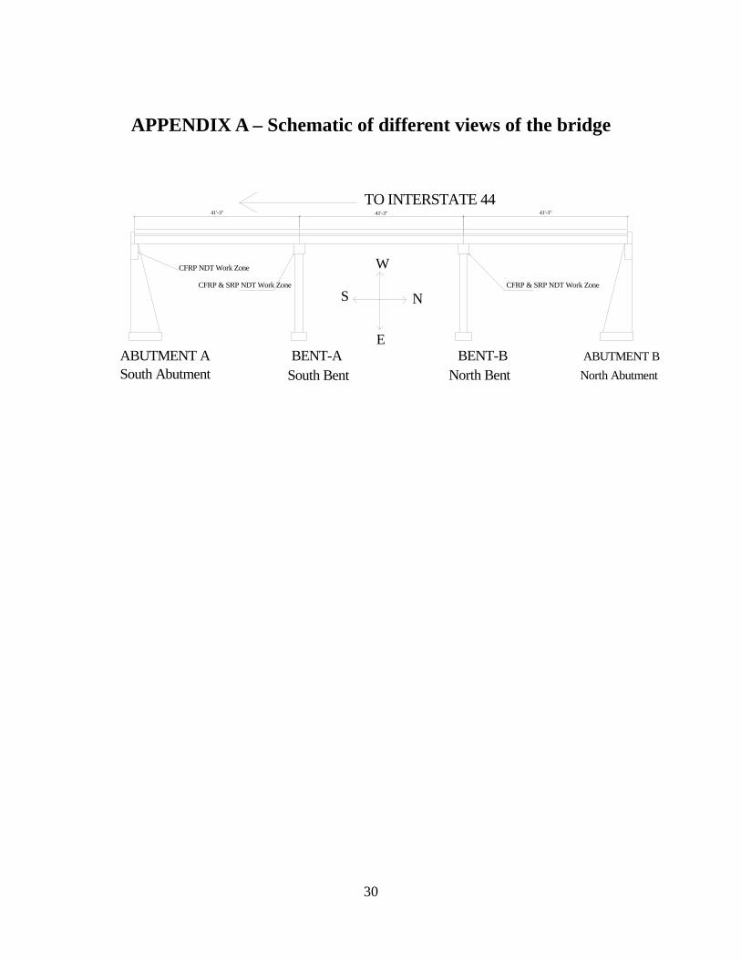
APPENDIX A – Schematic of different views of the bridge
TO INTERSTATE 44
ABUTMENT A BENT-A BENT-B ABUTMENT B
41'-3" 41'-3" 41'-3"
CFRP NDT Work Zone
CFRP & SRP NDT Work Zone CFRP & SRP NDT Work Zone
W
S N
E
South Abutment South Bent North Bent North Abutment
30
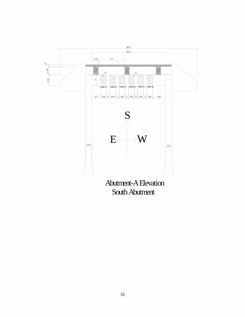
1'-1
0"6"
CFRP-A1 CFRP-A2 CFRP-A3 CFRP-A4 CFRP-A5 CFRP-A6
39'-5"
7'-7"1'-5"
2'1'-8" 1' 1'-8" 1' 1'-8" 1' 1'-8" 1' 1'-8" 1' 1'-8"
2" 2"
2'-7" 3'-8"
2'-6
"
1'-9" 1'-9"
S
E W
21'-3"
Abutment-A ElevationSouth Abutment
31

2'
20'
4'
2'
5 3/4" 6"1'-8"2'-8"
Half paintedSRP-B1
2'3"
3"
2'-6
"
West Side View of West PierSouth Bent (Bent A)
3' 3'
2'2'18
'-6"
1'-6"
2'-6
"
1'-6"
2' 2'
22'10'
0" Shear Strengthening
Flexural Strengthening
6'6'
CFRP-B2
CFRP-B1
2'-6
"2'
3"3"
9" 3"2'
3"
9"
1'-6
"1'-8"
10"
1'-8"
1'-5"
1'-8"10"1'-8"
1'-5"
EW
N
Bent-A ElevationSouth Bent
2'-8"
2'
4'
2'-6
"20
'
CFRP-B3
2'3"
3"
2'
1'-8"6"5 3/4"
Half painted
East Side View of East PierSouth Bent (Bent A)
32

2 '2 '
18'-6
"
3 '
2'
3 '
2'
3"3"
2'2'-6
"C F R P -B 5
6 ' 6 '1 0 '2 2 '
F le x u ra l S tre n g th e n in g
1 '-5 "
1'-6
"
1 '-6 "
1 '-8 "9 "
1 0 "0"
1 '-8 "
S h e a r S tre n g th e n in g
S
WE
B e n t-A E le v a tio n (B a c k V ie w )S o u th B e n t
33

4'
2'
20'
2'2'
-6"
2'-8"
CFRP-02
1'-6"
2'9'
-6"
East SideView of East PierBent B (North Bent)
1'-8"
6'22'
2'
3'
18'-6
"
2'
3'
2'
SRP-B3
6' 10'
Shear Strengthening
1'-8"
10"
1'-8"
1'-6
"9"3"
1'-6"
3"2'2'-6
"
1'-5"
Flexural Strengthening
1'-5"
2'
10" 1'-8" 9" 3"3"
2'-6
"
2'
SRP-B4
WE
S
Bent-B ElevationNorth Bent
2'
20'
4'
2'
2'-8"1'-8"
6" 6"
SRP-B2Half painted
3"3"
2' 2'-6
"
West SideView of West PierBent B (North Bent)
1'-6"
20'
2'
2'
4'
6"6"1'-8"2'-8"
9'-6
"
CFRP-01
2'
2'-6
"
East Side View of West PierBent B (North Bent)
18'-6
"
3'
2'
2' 2'
2'
3'
10'6'22'
6'
Flexural Strengthening
8'
CFRP-01
W
2'
N
Shear Strengthening
8'2'
ECFRP-02
1'-6"1'-6"
Bent-B Elevation (Back View)North Bent
34

APPENDIX B – Catalog of the microwave images of the CFRP patches obtained in 2004 using a rectangular waveguide probe
35

Patch 1(from left) on south abutment (May 18/04)
Picture of the patch with marked scanned area (300mm x 250mm)
Color images GrayscPerpendicular polarization
ale images
Parallel polarization
36

Patch 2 (from left) on south abutment (April 28/04)
Picture of the patch with marked scanned area (300mm x 350mm)
Color images Grayscale images Perpendicular polarization
Parallel polarization
37

Patch 3 (from left) on south abutment (May 18/04)
Picture of the patch with marked scanned area (330mm x 330mm)
Color images Grayscale images Perpendicular polarization
Parallel polarization
38

Patch 4 (from left) on south abutment (May 27/04)
Picture of the patch with marked scanned area (320mm x 320mm)
Color images Grayscale images Perpendicular polarization
Parallel polarization
39
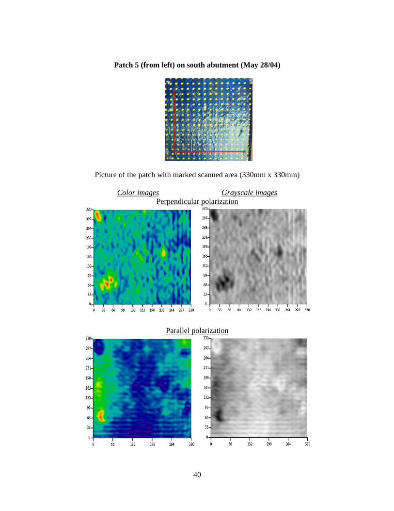
Patch 5 (from left) on south abutment (May 28/04)
Picture of the patch with marked scanned area (330mm x 330mm)
Color images Grayscale images Perpendicular polarization
Parallel polarization
40
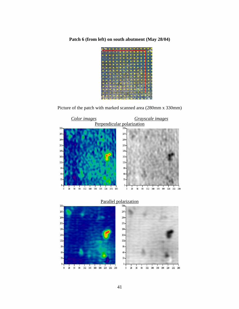
Patch 6 (from left) on south abutment (May 28/04)
Picture of the patch with marked scanned area (280mm x 330mm)
Color images Grayscale images Perpendicular polarization
Parallel polarization
41

Patch 1 (from left) on south bent (April 28/04)
Picture of the patch with marked scanned area (300mm x 360mm)
Color images Grayscale images Perpendicular polarization
Parallel polarization
42

Patch 2 (from left) on south bent (Jun 04/04)
Picture of the patch with marked scanned area (240mm x 400 mm)
Color images Grayscale images Perpendicular polarization
Parallel polarization
43
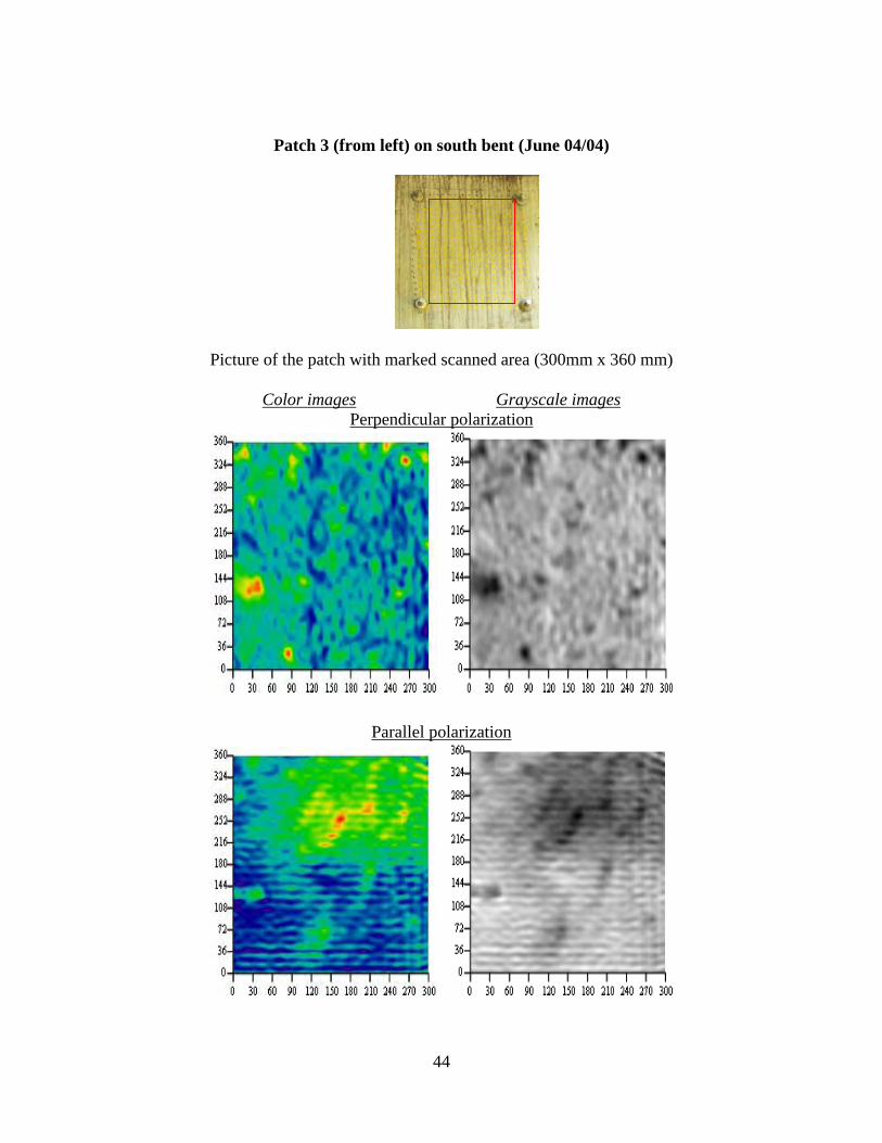
Patch 3 (from left) on south bent (June 04/04)
Picture of the patch with marked scanned area (300mm x 360 mm)
Color images Grayscale images Perpendicular polarization
Parallel polarization
44

Patch on east side of south bent (June 15/04)
Picture of the patch with marked scanned area (320mm x 380 mm)
Color images Grayscale images Perpendicular polarization
Parallel polarization
45

APPENDIX C – Catalog of the microwave images of the CFRP patches obtained in 2005 using a dual-polarized square wave-
guide probe
46

Patch 2 (from left) on south abutment (November 11/05)
Picture of the patch with marked scanned area (260mm x 340mm)
Grayscale images
Perpendicular polarization Parallel polarization
Compensated image
47
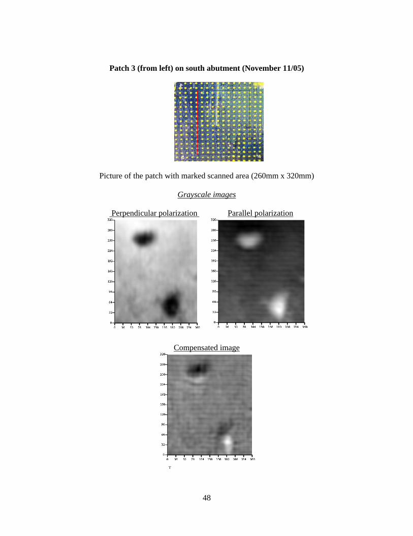
Patch 3 (from left) on south abutment (November 11/05)
Picture of the patch with marked scanned area (260mm x 320mm)
Grayscale images
Perpendicular polarization Parallel polarization
Compensated image
T
48
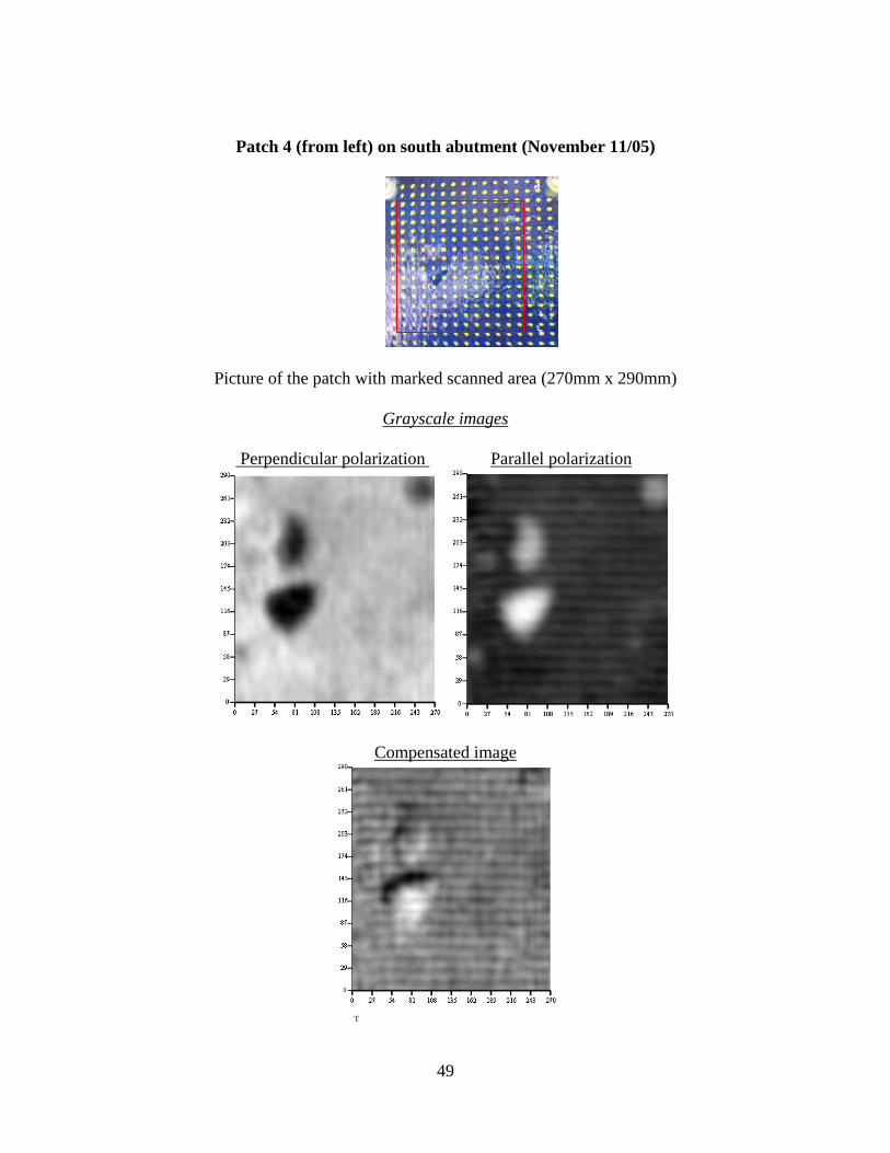
Patch 4 (from left) on south abutment (November 11/05)
Picture of the patch with marked scanned area (270mm x 290mm)
Grayscale images
Perpendicular polarization Parallel polarization
Compensated image
T
49

Patch 5 (from left) on south abutment (November 11/05)
Picture of the patch with marked scanned area (270mm x 290mm)
Grayscale images
Perpendicular polarization Parallel polarization
Compensated image
T
50
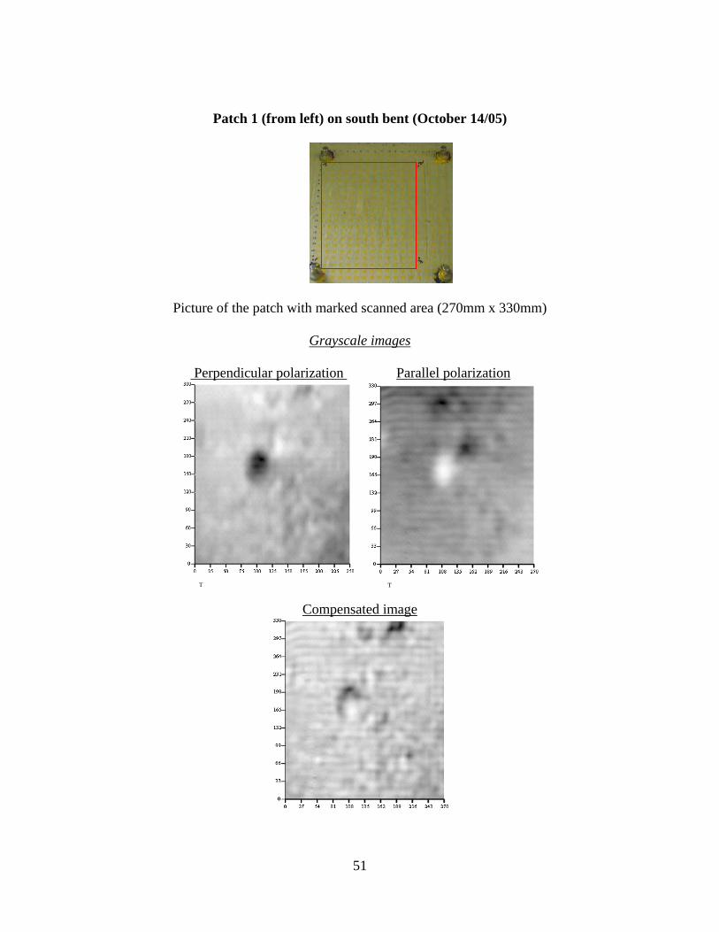
Patch 1 (from left) on south bent (October 14/05)
Picture of the patch with marked scanned area (270mm x 330mm)
Grayscale images
Perpendicular polarization Parallel polarization
T T
Compensated image
51

Patch 2 (from left) on south bent (October 14/05)
Picture of the patch with marked scanned area (250mm x 300 mm)
Grayscale images
Perpendicular polarization Parallel polarization
Compensated image
52

Patch 3 (from left) on south bent (November 4/05)
Picture of the patch with marked scanned area (270mm x 300 mm)
Grayscale images
Perpendicular polarization Parallel polarization
Compensated image
53
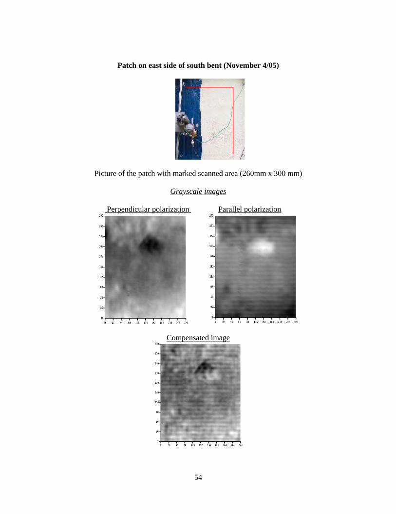
Patch on east side of south bent (November 4/05)
Picture of the patch with marked scanned area (260mm x 300 mm)
Grayscale images
Perpendicular polarization Parallel polarization
Compensated image
54

APPENDIX D – Catalog of the microwave images of the CFRP patches obtained in 2006 using a dual-polarized square wave-
guide probe
55

Patch 1(from left) on south abutment (June 5/06)
Picture of the patch with marked scanned area (260mm x 300mm)
Grayscale images
Perpendicular polarization Parallel polarization
Compensated image
56

Patch 2 (from left) on south abutment (June 5/06)
Picture of the patch with marked scanned area (260mm x 340mm)
Grayscale images
Perpendicular polarization Parallel polarization
Compensated image
57

Patch 3 (from left) on south abutment (June 5/06)
Picture of the patch with marked scanned area (260mm x 320mm)
Grayscale images
Perpendicular polarization Parallel polarization
Compensated image
58
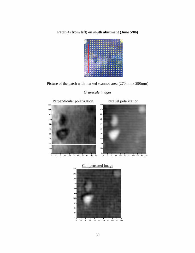
Patch 4 (from left) on south abutment (June 5/06)
Picture of the patch with marked scanned area (270mm x 290mm)
Grayscale images
Perpendicular polarization Parallel polarization
Compensated image
59

Patch 5 (from left) on south abutment (June 5/06)
Picture of the patch with marked scanned area (270mm x 300mm)
Grayscale images
Perpendicular polarization Parallel polarization
Compensated image
60

Patch 6 (from left) on south abutment (June 5/06)
Picture of the patch with marked scanned area (280mm x 300mm)
Grayscale images
Perpendicular polarization Parallel polarization
Compensated image
61

Patch 1 (from left) on south bent (May 26/06)
Picture of the patch with marked scanned area (270mm x 330mm)
Grayscale images
Perpendicular polarization Parallel polarization
Compensated image
62

Patch 2 (from left) on south bent (May 26/06)
Picture of the patch with marked scanned area (250mm x 300 mm)
Grayscale images
Perpendicular polarization Parallel polarization
Compensated image
63

Patch 3 (from left) on south bent (June 5/06)
Picture of the patch with marked scanned area (270mm x 300 mm)
Grayscale images
Perpendicular polarization Parallel polarization
Compensated image
64
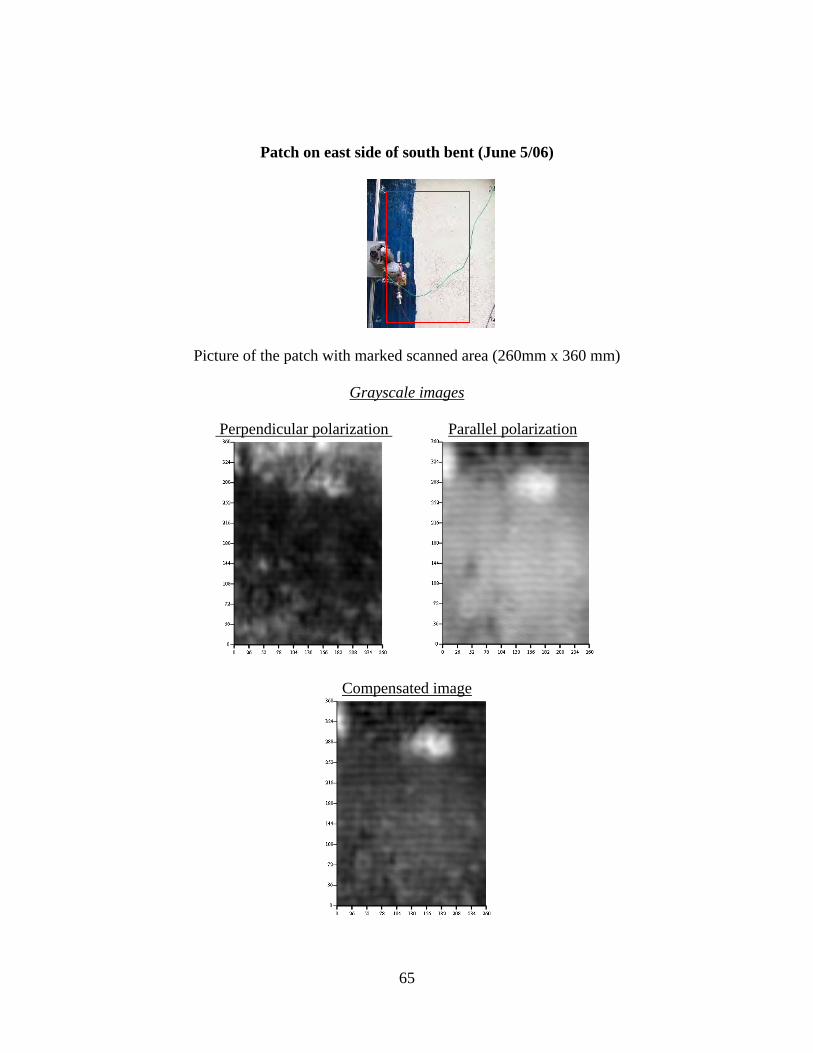
Patch on east side of south bent (June 5/06)
Picture of the patch with marked scanned area (260mm x 360 mm)
Grayscale images
Perpendicular polarization Parallel polarization
Compensated image
65

Missouri Department of Transportation Organizational Results P. O. Box 270 Jefferson City, MO 65102
573.526.4335 1 888 ASK MODOT [email protected]