Embed Size (px)
Citation preview
IC Engine System
Presented ByANSYS Inc.

• Background and Motivation• IC Engine System
• Introduction• Scope• Properties• Work flow for cold flow and port flow simulations• Advanced setup/customization• Other useful features
• Demo• Future Plans• Summary
Outline
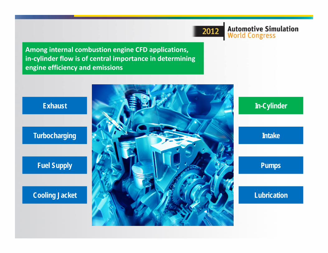
In-Cylinder
Cooling Jacket Lubrication
Intake
Exhaust
Pumps
Turbocharging
Among internal combustion engine CFD applications, in‐cylinder flow is of central importance in determining engine efficiency and emissions
Fuel Supply

Recent ANSYS Progress in IC Engine Modeling
20102009
• Continuous progress with each Fluent release bringing advancements in physics and meshing
Fluent R12IC engine report, IC specific vaporization laws, coherent
flamelet model, EGR, ignition UDF
Fluent R13Key‐frame mesh, mesh smoothing,DPM and combustion extensions:
multiple spark model, Veynante ECFM for LES, KHRT break‐up model,
Fluent R14.5Sprays: spray angle vs. crank angle,
cone injection sector meshesMesh related: 2nd order in time MDM, contact detection, cutcell w. BL remesh
2011 2012
Fluent R14Aftertreatment: selective
catalytic reduction, catalytic converter light offCombustion: G‐eqnMultiphase: SSD
* The Workbench IC Engine system uses a well‐tested subset of Fluent features

• Manual Approach for simulating in‐cylinder flow– Gather the required user input needed to accurately model the
user’s specific engine.– Prepare the Geometry and Mesh:
• Decompose the geometry in a manner suitable for modeling the motion of valves and piston and then create the mesh
• Manually decomposing the geometry and meshing takes between 6 hours and a couple of days, depending on experience
• Learning curve for manual geometry decomposition and meshing is very steep!!
– Set‐up and run the simulation: • Setting up the case requires knowledge of models like dynamic
mesh, reacting flows, discrete‐phase etc.– Analyze and interpret results
Motivation
IC Engine Geometry
Geometry Decomposition
Mesh Creation
Solver Setup
IC Engine Results
WB‐ICE toolPerform following operations semi‐
automatically
Geometry Decomposition
Solver Setup
Mesh Creation
Automatic Report
Generation
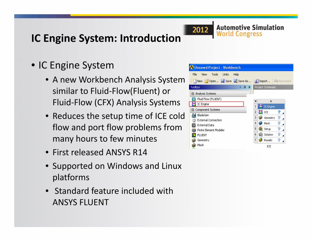
• IC Engine System• A new Workbench Analysis System similar to Fluid‐Flow(Fluent) or Fluid‐Flow (CFX) Analysis Systems
• Reduces the setup time of ICE cold flow and port flow problems from many hours to few minutes
• First released ANSYS R14• Supported on Windows and Linux platforms
• Standard feature included with ANSYS FLUENT
IC Engine System: Introduction

• Automated geometry preparation and mesh generation for all 4 stroke engines– any number of valves– all standard shapes of piston at the given crank angle
• Automated case setup for “cold‐flow” and “port‐flow” type simulations based on the best practices– including mesh motion
• User hooks for complex physics setup, e.g. spray injection, combustion simulation
• Automated report generation
Scope of IC Engine System

IC Engine System Properties
These IC inputs can be defined asParameters
Can be used to setup a customized case
Can be used to perform custom post‐processing
For engines with piston pin offset
User can hook boundary condition profiles

ANSYS Workbench
Workbench ICE System
DesignModeler
FLUENT Solver
CFD Post
Single Mesh
ANSYS Meshing
Multiple Meshes
(keyframes) (new R14.5)
Automatically Generated Reports
CAD

Cold Flow Simulation SetupUsing IC Engine System:

• Automatic preparation of geometry for meshing• Automatic meshing including inflation layers and layering zones
• Automatic setup dynamic zones, events, and solver settings
• HTML report creation• Reduces the turnaround time (CAD import to CFD setup) to less than an hour
Cold Flow Simulation using IC Engine System

Geometry Preparation

Geometry Inputs
Basic GeometryInformation
Valve geometry andprofile information
Optional Animation Inputs
Advanced Options

Mesh Generation

Different Meshing Configurations
4 layers between valve and valve‐seat at fully‐closed position of valve
one layer in the gap at fully‐closed position of valve

Inflation layer in the port
No Inflation layer in the port
Different Meshing Configurations

Different Meshing Configurations
No decomposition in chamber region for engines with very little squish at TDC or pistons with valve recess regions
Decomposition in combustion chamber region for layered mesh

• IC Engine System will automatically setup the problem– Reads the valve and piston profile– Create various dynamic mesh zones– Create interfaces required for dynamic mesh setup– Set up the dynamic mesh parameters– Create all the required events, to model opening and closing of valves, and corresponding modifications in solver settings and under‐relaxations factors
– Set up the required models– Set up the default boundary conditions and material– Set up the default monitors– Initialize and patch the solution
Solver Setup

• Once the solution is complete, tool creates a detailed report with all the settings , events,
results and images.
HTML Report

Port Flow Simulation using IC Engine System

• New feature in upcoming ANSYS R14.5 Release• Prepares the geometry automatically• Automatic meshing using hybrid and cut‐cell approaches
• Setup and solution strategy based on the best practices
• Automatic saving of important images and HTML report creation
• Reduces the turnaround time (CAD import to CFD setup) to less than an hour
Port Flow Simulation using IC Engine System

Automatic Geometry Preparation• Moves the valve to appropriate position• Deactivates the closed valve and deletes the port automatically
• Removes the piston‐bowl (if needed) and extend the cylinder to appropriate length
• Create different shapes of inlet/outlet plenum• Automatically creates the swirl/tumble planes at the given position
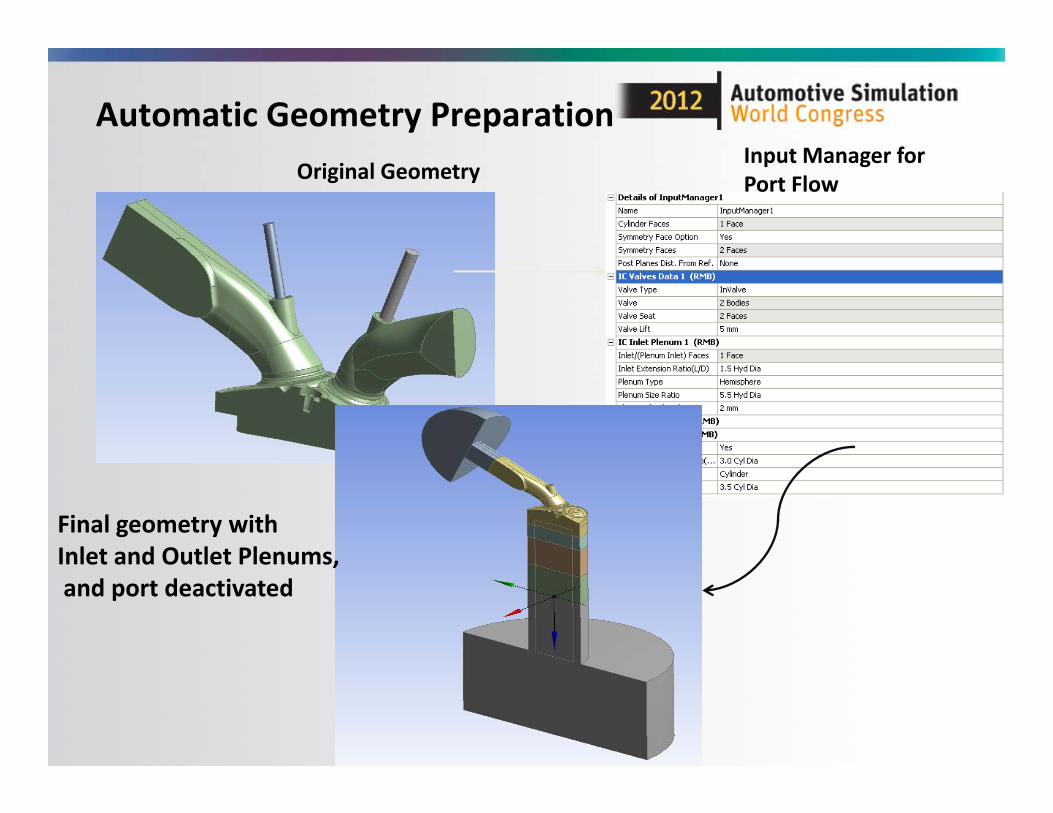
Original GeometryInput Manager for Port Flow
Final geometry with Inlet and Outlet Plenums,and port deactivated
Automatic Geometry Preparation

Geometry Decomposition

• Cutcell and hybrid meshing support• Create proper mesh controls and sizing to get better mesh in the chamber and valve gap
• Boundary layers in both hybrid and cutcellmeshing
Automatic Meshing

Automatic Meshing
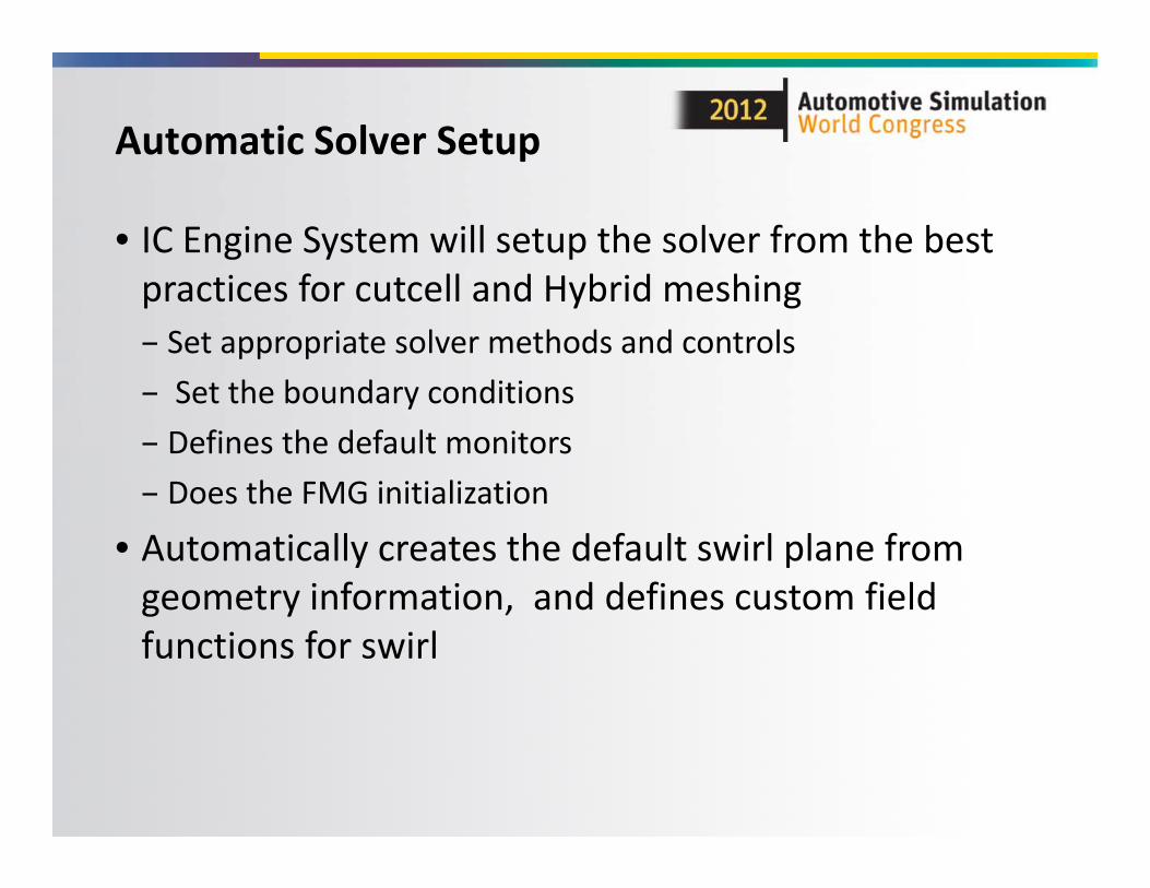
• IC Engine System will setup the solver from the best practices for cutcell and Hybrid meshing– Set appropriate solver methods and controls– Set the boundary conditions– Defines the default monitors– Does the FMG initialization
• Automatically creates the default swirl plane from geometry information, and defines custom field functions for swirl
Automatic Solver Setup

HTML Report:

•Demo ( 5‐6 min recorded demo of cold flow and port
flow)

• A strong regression suite– More than 15 engines with various topologies from different customers are there in our regression suite, which runs on daily basis, to maintain the stability and high quality of software
– For each of these engines geometry preparation, meshing, and setup for cold flow case is within 20 min, and for port flow this is within 30 min
Regression and Time Statistics:
Documentation:
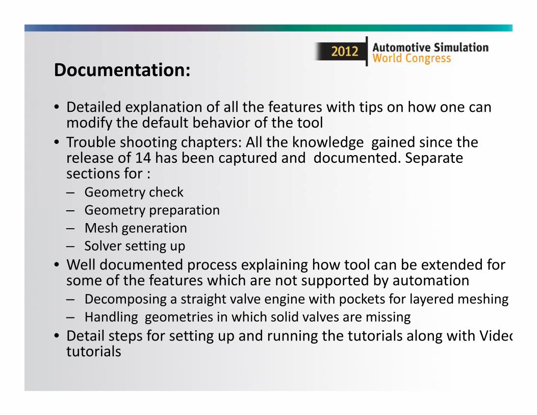
• Detailed explanation of all the features with tips on how one can modify the default behavior of the tool
• Trouble shooting chapters: All the knowledge gained since the release of 14 has been captured and documented. Separate sections for :– Geometry check– Geometry preparation– Mesh generation– Solver setting up
• Well documented process explaining how tool can be extended for some of the features which are not supported by automation– Decomposing a straight valve engine with pockets for layered meshing– Handling geometries in which solid valves are missing
• Detail steps for setting up and running the tutorials along with Videotutorials

Extending the Tool (Advanced Users)

• User will be able to setup advanced physics using pre‐iteration and post‐iteration journal hooks
• Using pre‐iteration journal hooks user should be able to setup combustion problem in IC Engine system:
• Define profile, udf , and chemkin, file path and also other variables
• Compile and hook the udf, also define some udf related variables
• Deactivate port fluid zones• Set up energy model, turbulence model, species model and dpm models
• Define injections
Advanced solver setup usingjournal customization.

Setting up Combustion:
Pre‐iteration Journal
Cold‐Flow Setup
Combustion Setup with
Spray

Pre‐iteration Journal filefor combustion:
File Handling
Model Control
Injection Data
Setup Method
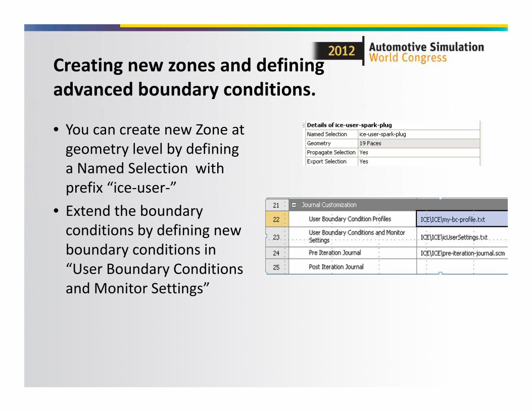
• You can create new Zone at geometry level by defining a Named Selection with prefix “ice‐user‐”
• Extend the boundary conditions by defining new boundary conditions in “User Boundary Conditions and Monitor Settings”
Creating new zones and defining advanced boundary conditions.

Handling Engines withCrevice Region
Crevice Region
Interface
Hex Mesh
• Though, right now, the tool will not do any special treatment for crevice region, one can extend the tool by doing few manual operations to get more control in crevice region
Separate the crevice volume and define proper mesh
Define interfaces to handle this new crevice volume

Other Useful Features

Key grid support
– Automatic crank angle specific decomposition– Create mesh as per the crank angle position– Parametric support to get meshes at different crank angles• You can setup up to the mesh once, and then you can create any number of design points with the exposed parameters like : crank angles, minimum lift, or connecting rod length and update the design points, you will have the appropriate mesh file ready at those given crank angles without any manual intervention

Key grids based on the crank angle
Geometry and Mesh at crank angle near TDC
Geometry and Mesh at crank angle near BDC

Usability Features
• Animation of valve and piston motion for the cold flow simulation at geometry level
• Parameter support for port‐flow solution and mesh generation in cold flow
• User can start the cold flow simulation from any crank angle , all the settings will be taken care automatically– This saves a huge amount of time ; earlier people use
to reach the required crank angle by mesh motion which takes a lot of time
• Automatic cut planes and views in AMP for better visualization of the mesh

• Smooth transition from Cold‐flow to Spray and Combustion• Automated setup for combustion analysis• Improve meshing options by
• Automatically Switching between different tailored meshes during simulation (Key‐grid or mesh‐replacement approach)
Future Plans
Note: The plans are still tentative and time‐lines, priorities etc. needs to be worked out

• New “standard” feature in ANSYS‐FLUENT for In‐Cylinder simulations
• Automates in‐cylinder model creation• Extensively tested on different engine configurations
• Supported on Windows and Linux• Quick to learn and easy to use!• Provides hooks for custom in‐cylinder simulations
Summary

Appendix

Work Flow

Mesh configuration of IC Engine system for a typical canted valve engine
No Fluid Zone Name
Mesh type
1 fluid‐ch Tet mesh
2 fluid‐valveID‐ib
Sweep mesh with at least one layer at the top
3 fluid‐valveID‐port
Tet mesh with or without prism layer
4 fluid‐valveID‐vlayer
Layered mesh with 1 or 4 layers
5 fluid‐layer‐cylinder
Layered mesh
6 Fluid‐piston Tet mesh

Various zones and named selection created automatically for a typical canted valve engine.
Geometry decomposition

Smoothing‐Layering approach
smoothing smoothinglayering
To retain at least 4 layers of cells between valve and valve seat, throughout cycle

• Piston should be at TDC position (in R14.0)
• For Parasolid geometry, set the Clean Bodies option to ‘No’
• Imported geometry should have only one flow volume with solid valves
• Ensure that the valves are not extracted from the port volume in the initial geometry
• Ensure that the valve stem protrudes out of the port body
• Ensure that the valve is centrally aligned to the valve guide. An off‐centered valve can result into failures and wrong results
Troubleshooting: Geometry Check

• If cylinder chamber meshing fails => Delete its pinch controls and execute the
meshing again• If some faces belonging to a named
selection group are not selected for the Geometry option they belong to, then the warning is displayed => Add these faces to the Geometry list of
the Named Selection it belongs to• If there are any small faces causing a
meshing failure, then these faces should be merged with their adjacent faces using Virtual Topology
• If V‐layer meshing fails => Try to project and imprint the edge of the
valve face on the valve seat, in the direction of the valve– This will split the valve seat. Then
decompose the geometry again. This procedure will create a proper sweep mesh in the vlayer.
Troubleshooting: Mesh Generation

• V‐layer meshing can fail in some cases where the face has a step. • Select ‘Show the Problematic Geometry’ from the context menu of the error message in the Messages window. This will point to the face which has the step
• Reduce the V Layer Slice Angle parameter in the Input Manager, such that the face is split into two. Then reset the Mesh cell and follow the meshing procedure to re‐mesh the geometry.
Troubleshooting: Mesh Generation

Straight Valve Engines with Valve Pockets
• Fully layered mesh can be created for straight valve diesel engines with valve pockets‐ Instructions can be provided upon request (available in R14.5 ICE Manual)Example: Hex mesh created for layering