Embed Size (px)
Citation preview

Presentation on
Latest Developments in EMUs (Specific to Mumbai Suburban System)
Alok Kapoor,
Dy. Chief Electrical Engineer
Mumbai Railway Vikas Corporation
Mass Urban Transport Projects
8th BIMSTEC Training Course on Design and Maintenance of
Passenger Coaches
Railway Staff College, Vadodara
2nd September 2008

Mumbai Urban
Transport Project
(Rail Component)
Mumbai Railway Vikas Corporation

MUMBAI SUBURBAN RAILWAY SYSTEM
• Mumbai has been the commercial capital of India since pre-independence days
• Due to its peninsular geography, the city has grown linearly
• Britishers realized that only an efficient suburban railway system can become the prime mover of growth for the city
• Suburban railway system set up in 1925
• Latest technologies of 1500v DC traction and DC Electric Multiple Units available at that time used.

Mumbai Suburban Railway System An Overview
• 319 route Kms.
• 876 Track Kms (including 52 Kms already added in MUTP).
• 6.3 million passengers per day.
• 2385 trains per day
• Fleet of 227 rakes (9 car eq.) which are run in 9 and 12 car compositions.
• Mumbai Suburban Railway System is a part of Indian Railways which is a department of the Central government.

Units
1951/ 52
1960/ 61
1970/ 71
1980/ 81
1990/ 91
2000/ 01
2004/ 05
Passenger carried
Million
292
454
915
1459
1795
2275
2314
% Annual Compounded Growth Rate
5.0
7.3
4.8
2.1
2.4
0.43
Passenger KMs
Million
4031
6365
15123
27392
40462
61195
68362
% Annual Compounded Growth Rate
5.2
9.0
6.1
4.0
4.2
2.8
Average trip length
Km
13.8
14.0
16.5
18.8
22.5
26.9
29.54
% Annual Compounded Growth Rate
0.2
1.7
1.3
1.9
1.8
2.37
Suburban Traffic Growth
Lack of Investment
• The traffic demand was mainly due to phenomenal growth of population in the northern suburbs whereas the main business district continued to be in south Mumbai
• Development/Property tax used for roads & other infrastructure but not for suburban railway system
• Indian Railways also unable to provide funds for expansion as suburban system is loss making.

Growth In Mumbai Sub-urban EMU Trains
0
500
1000
1500
2000
2500
3000
3500
1951-1952 1961-1962 1971-1972 1981-1982 1991-1992 2001-2002 2004-2005
Year
Avera
ge N
o.
Of
Pass
en
ge
rs P
er
Day
Serie
s1

Average Trip Length
0
5
10
15
20
25
30
35
1951-1952 1961-1962 1971-1972 1981-1982 1991-1992 2001-2002 2004-2005
Year
Av
era
ge
Tri
p L
en
gh
t(K
ms
)
Series1

Mumbai Urban Transport Project
(Rail Component)
• Rail projects were identified in 1998 through the project preparatory studies with the objective of:
• Bring down the crowding in peak hour peak direction 9-car train to 3000 passengers as against existing around 5000.
• Segregate the suburban train operation from the main line passenger and freight services.

Mumbai Urban Transport Project
(Rail Component)
• Completion over a time frame of ten to twelve years.
• Total cost in excess of Rs. 10,000 crores
• MUTP (Rail Component) bifurcated in phases for the purpose of World Bank funding.
Institutional Arrangement for Rail
Component of MUTP
• Ministry of Railways & Government of
Maharashtra have set up Mumbai
Railway Vikas Corporation Ltd. to
undertake rail related works of MUTP for: • Better coordination between GOM & MOR
• Cutting down the bureaucratic delays

• Implement the rail infrastructure projects in Mumbai suburban sections.
• Commercial development of railway land and airspace in Mumbai area to raise funds for suburban railway development.
• Resettlement & Rehabilitation of Project Affected Households.
OBJECTIVES OF MRVC

• Phase I includes Works required to bring
down the peak hour loading from 5000 to
3600 & to be completed by June 2009.
MUTP Phase I
(Rail Component)

MUTP Phase I (Rail Component) • New Lines: • Quadrupling of Borivali-Virar section 416.0 cr. • WR 5th line Santacruz-Mahim 59.0 cr. • Kurla Thane Additional pair of lines 166.0 cr.
• Sub-Total (New Lines) 641.0 cr.
• EMU procurement & manufacture: 1359.2 cr.
• DC to AC Conversion 380.4 cr.
• Resettlement & Rehabilitation: 290.0 cr.
• Optimisation & Other Works: • Optimisation of Western Railway 50.1 cr. • Optimisation of Central Railway 99.5 cr. • Optimisation of Harbour line 19.7 cr • Virar Car Shed 93.0 cr • Maintenance facilities for EMUs 64.3 cr. • Stabling lines for EMUs 48.5 cr. • Track Machines 31.3 cr. • Institutional strengthening & studies 48.2 cr. • Sub-Total 454.6 cr.
• Grand Total 3125.2 cr
EMU PROCUREMENT

EMU Procurement:
Total No. of rakes - 174, 9 Car.
• MRVC Contract - 101, 9 Car.
• GP-194 - 56, 9 Car.
• GP-194 (30%) - 17, 9 Car.

Progress
1st Rake 12th Nov. 2007 (W.R.)
2nd Rake 17 Dec. 2007 (W.R.)
3rd Rake 13th Jan. 2008 (W.R.)
4th Rake 21st Feb. 2008 (C.R)
5th Rake 7th April 2008 (C.R)
6th Rake 13th May 2008 (CR)
7th Rake 26th May 2008 (CR)
8th Rake 13th June 2008 (CR)
9th Rake 4th July 2008 (CR)
10th Rake 31st July 2008 (CR)

Progress
11th Rake 8th Aug. 2008 (C.R.)
12th Rake 17th Aug. 2008 (C.R.)
13th Rake 23rd Aug. 2008 (C.R.)
14th Rake Under commissioning (C.R.)
15th Rake Received on 26th Aug. 2008
With the introduction of new rakes
126 additional services (74,12 car & 52, 9-car)
123 services earlier running with 9-car have been
converted to 12-car

28-07-07
Hon’ble Chief Minister
inspecting the New EMU Rake
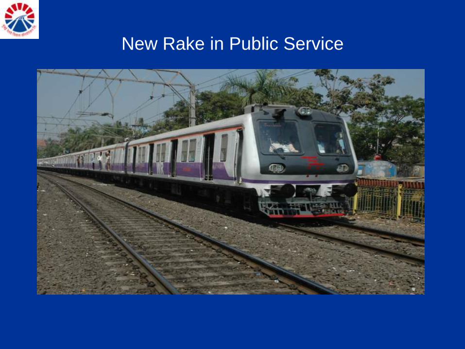
New Rake in Public Service

New Rake in Public Service

Improved Features
of
MRVC EMU Rake
MRVC
Technical Features
MRVC

Details of Equipments

System Requirement
• Max. Axle load 20.32 tones
• Typical Run 1.5 km on level tangent track in less than 113 sec
• Acceleration (average 0.54 m/s2 with SDCL. Jerk: 0.75 m/s3
from 0 to 40 Km/h)
• Deceleration 0.76 m/s2 (100 to 50 kmph) 0.84 m/s2
(50 kmph to Stand still)
• Traction voltage 1500 volt DC and 25 kv AC (Dual Voltage)
• Bogie suspension Metallic springs in Primary, Air springs in
Secondary.
• Brakes Blending of Regenerative and Frictional brakes
• Main / Aux. Converter IGBT based
• SEC (KWH /1000 GTKm) 29
• Life 25 year

Improved Performance Features of MRVC EMUs
Features MRVC EMUs Existing
EMUs
• Acceleration with super
dense crush loading
0.54 m/s2 0.36 m/s2
• Decelaration 0.76 m/s2 (100 to 50 kmph)
0.84 m/s2 (50 to stand stilll)
0.6 m/s2
•Max Service Speed 100 kmph 80 kmph
• Specific Energy Consumption 27 units per Thousand Gross
Ton Km
40 KWH/100
GTKM

Improved Performance Features of MRVC EMUs
• Traction Motor Power Rating 240 kW 187 kW
• Traction Control Microprocessor based
control & Fault Diagnostics
Resistance
Control
• Auxiliary Power Supply
Capacity
70 kW 12 kW
•Passenger Information System Menu Driven Digital Audio
–Visual system in each
coach
Normal PA
System
Commuters will get information like which is the next halting
station & on which side platform will be there, on speakers as
well as on LED display panels.

Main Transformer
Traction Transformer
Continuous KVA rating 1250 KVA
Continuous Secondary Voltage (at 25KV
primary)
2 X 950 V
No. of secondary windings 2
Type of cooling ODAF
Type of coolant Mineral oil
Weight App. 3100 Kg
Efficiency App. 96%

Power converter-inverter
Traction Converter Nominal Input voltage 2 x 950 V AC (AC Mode)
1500 V DC (DC Mode)
Nominal DC link voltage 1800 V DC (AC Mode)
1500 V DC (DC Mode)
No. of 4 quadrant choppers (4QC) 2 (IGBT based)
No. of pulse with modulated inverters (PWMI) 2 (IGBT based)
Continuous rating per 4QC 620 KW
Continuous rating per PWMI 535 KW
Output voltage 1217 (line to line, fundamental value)
Control Microprocessor control
Cooling Force air cooled
Weight
App. 2200 Kg
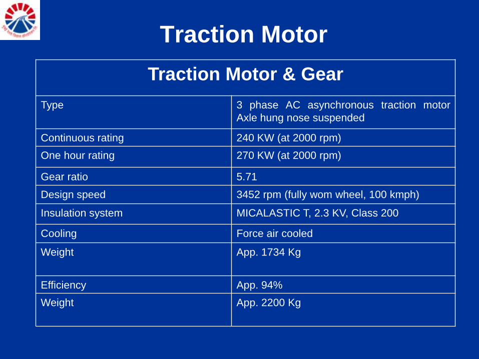
Traction Motor
Traction Motor & Gear
Type
3 phase AC asynchronous traction motor
Axle hung nose suspended
Continuous rating 240 KW (at 2000 rpm)
One hour rating 270 KW (at 2000 rpm)
Gear ratio 5.71
Design speed 3452 rpm (fully wom wheel, 100 kmph)
Insulation system MICALASTIC T, 2.3 KV, Class 200
Cooling Force air cooled
Weight
App. 1734 Kg
Efficiency App. 94%
Weight
App. 2200 Kg

Auxiliary Systems
Auxiliary Converter & Battery Charger
Nominal input voltage 1500 V DC
Nominal output voltages 415, 3 ph. AC, 50 Hz
110V, 1 ph AC, 50 Hz
110 V DC
Ratings 415, 3 ph. AC, 87 Hz
110V, 1 ph AC, 20 Hz
110 V DC – 9 KW
Semiconductor device IGBT based
Control Microprocessor control
Cooling Force air cooled
Weight App. 1200 Kg
Efficiency > 90%

Power circuit

Typical run in a
Mumbai suburban system

Passenger Friendly Features
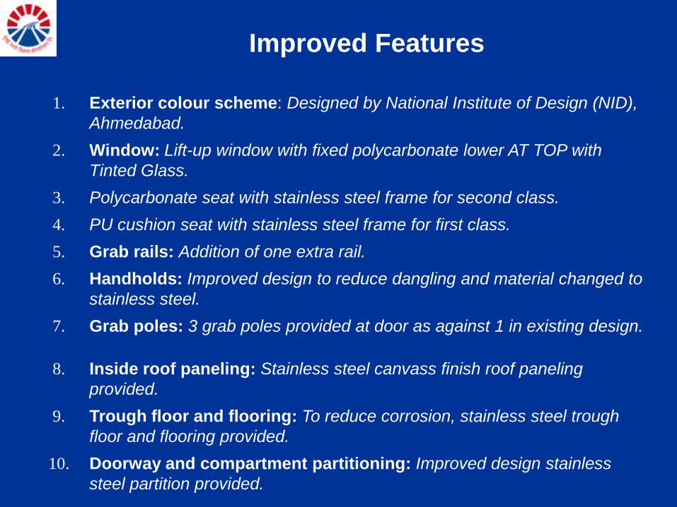
Improved Features
1. Exterior colour scheme: Designed by National Institute of Design (NID),
Ahmedabad.
2. Window: Lift-up window with fixed polycarbonate lower AT TOP with
Tinted Glass.
3. Polycarbonate seat with stainless steel frame for second class.
4. PU cushion seat with stainless steel frame for first class.
5. Grab rails: Addition of one extra rail.
6. Handholds: Improved design to reduce dangling and material changed to
stainless steel.
7. Grab poles: 3 grab poles provided at door as against 1 in existing design.
8. Inside roof paneling: Stainless steel canvass finish roof paneling
provided.
9. Trough floor and flooring: To reduce corrosion, stainless steel trough
floor and flooring provided.
10. Doorway and compartment partitioning: Improved design stainless
steel partition provided.

Improved Features
11. Coach door: Powder coated aluminum door with polycarbonate
window provided.
12. Luggage rack: Stainless steel rack provided.
13. Ventilation: Forced air ventilation system provided.
14. Sidewall and end wall panel: FRP panels used for better aesthetics
and long life.
15. Head code: LED type head code provided.
16. Secondary suspension: Pneumatic spring used to improve comfort
and safety.
17. Signage: NID design signage with stickers.
18. Improvement in coach insulation: Recron thermal wadding used.
19. Rainwater gutter: Stainless steel water gutter provided.
20. Passenger information system

1. Exterior colour scheme: Designed by
National Institute of Design (NID), Ahmedabad.

Exterior Colour Scheme
Existing EMU

2. Window: Lift-up window with fixed polycarbonate lower
AT TOP with Tinted Glass.

Windows and Protective Window screen
Existing EMU

3. Polycarbonate seat with stainless steel frame
for second class.

4. PU cushion seat with stainless steel frame for first class.

Seats of Existing Rakes
Existing EMU

5. Handholds & Grab rails : Improved design to reduce
dangling and material changed to stainless steel.

7. Grab poles: 3 grab poles provided at door as against 1
in existing design.

8. Inside roof paneling: Stainless steel canvass finish roof paneling
provided.

9. Trough floor and flooring: To reduce corrosion,
stainless steel trough floor and flooring provided.

Trough Floor and flooring
Existing
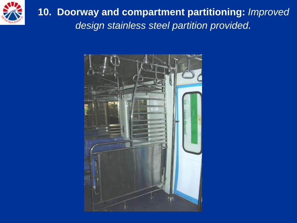
10. Doorway and compartment partitioning: Improved
design stainless steel partition provided.

11. Coach door: Powder coated aluminum door with
polycarbonate window provided.

12. Luggage rack: Stainless steel rack provided.

13. Ventilation: Forced air ventilation system

14. Sidewall and end wall panel: FRP panels used for
better aesthetics and long life.

15. Head code: LED type head code provided.

16. Secondary suspension: Pneumatic
spring used to improve comfort and safety.

Secondary suspension
Existing

17. Signage: NID design signage with stickers.
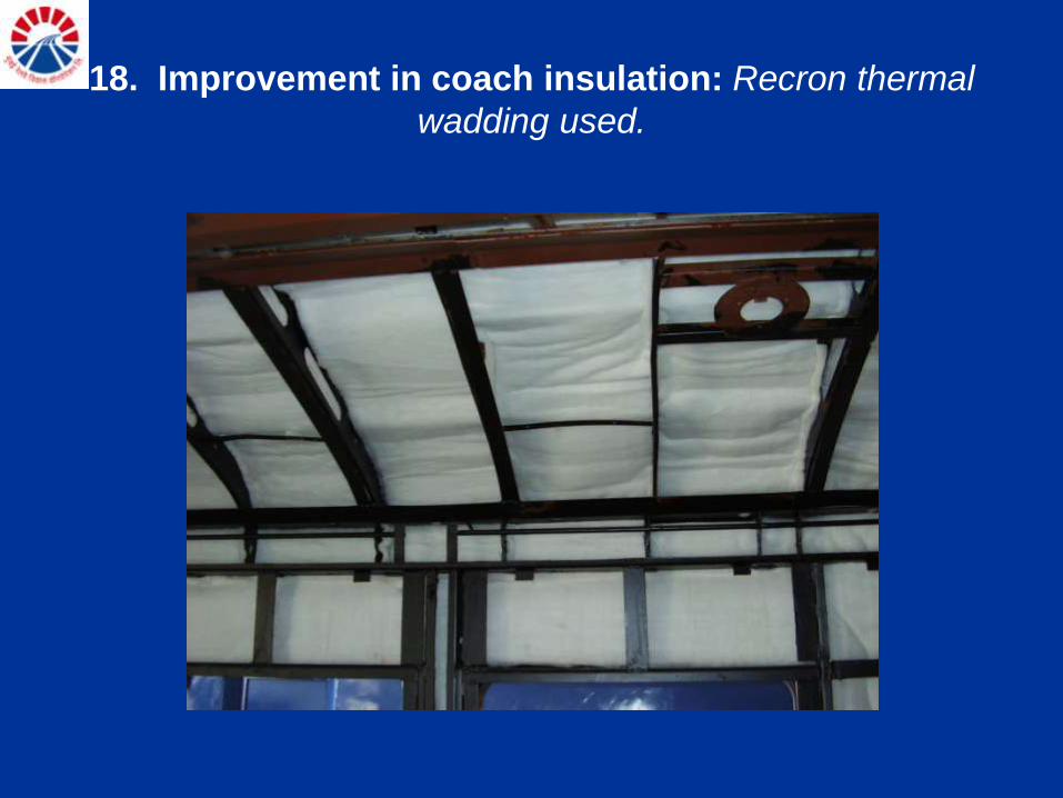
18. Improvement in coach insulation: Recron thermal
wadding used.

Improved Lighting : illumination levels increased to 300 lux.

19. Rainwater gutter: Stainless steel water gutter provided.

20. Passenger information system

Details of Cost
Cost 20 Crores
Cost of Imported Rake 60 crores

Ventilation System

VENTILATION Problem:

• Natural Air Roof Ventilators
• Electric Ceiling Fans
Age old Ventilation Arrangement on D.C. EMUs
and its problems
Sr.
No.
Coach
Type
No. of Fans /
Coach
Watt / Fan Capacity
of Each
Fan in
m3/hr.
Total
Wattage of
Fans
Total Capacity
of Fans in
m3/hr.
1. D.T.C. 26 38 Watt 50 m3/hr. 988 1300 m3/hr.
2. M.C. 22 38 Watt 50 m3/hr. 936 1100 m3/hr.
3. T.C. 26 38 Watt 50 m3/hr. 988 1300 m3/hr.

• Year 1970, High Capacity Ceiling Fans(80 m3/hr)
• Year 1984, Roof Ventilation Design with large
opening
Efforts made in past to Improve Ventilation

• Year 1996, Provision of louvers in sidewall of coaches alongwith exhaust fans in the ceiling
to increase entry of fresh air

• Provision of openings in Coach Floor to permit entry of Fresh Air
• Year 2003, Electric Blowers for Ventilation

Improved Ventilation System in MRVC Racks

Ventilation system
• MRVC procured a portable carbon dioxide meter and measured the CO2 levels inside the running trains.
• The CO2 levels in the existing SDCL condition was 2500 ppm.

• Detailed study was carried out referring ANSI/ASHRAE standard to modify the RDSO specification.
• ANSI/ASHRAE standard 62-2001 recommends that the maximum indoor CO2 concentration should be less than 700 ppm above the outdoor air concentration
Ventilation system

• Passenger Loading per coach:
– Seating Capacity 90 passengers
– Normal standing for peak 90 passengers
– Total passengers traveling 570 passengers
in SDCL
Ventilation system
Fresh Air Requirement

Ventilation system
Fresh Air Requirement
• CO2 Generated per Coach:
– CO2 generated per passenger .018 m3/hr
– CO2 generated by 570 10 m3/hr
passengers in SDCL
• Calculation of Fresh Air Requirement:
– Fresh Air Required = Total CO2 generated Permissible PPM
= 10 m3/hr 700 X 10-6 = 15000 m3/hr
ADDITIONAL FRESH AIR REQUIRED = 15000 m3/h

The Design Concept :
VENTILATION SYSTEM

The Design Concept :
VENTILATION SYSTEM

Basic Design:

• Mounting arrangement
• Supply Air duct
• Electric Blower
Two three-phase induction motors are provided in each Air Handling
Unit.
415 V, 50 Hz , 1,1 kW/ 4 poles
IP56
Frame size 90L
Insulation class H
Ambient temperature 65 °C
Capability to withstand shock and vibration loads
Blowers: The blower wheels are directly coupled on the motor shaft.
Blower and blower housing made from stainless steel 304
Blower wheel is made from galvanized steel

• Electrical requirements
• Ventilation Control Mechanism with respect to
Load and Temperature variations under normal
conditions
Percentage
Occupancy
Temperature AHU Control
(No. of running AHU/car)
Load weight
signal
Temperature sensor signal
from TCC
% °C
if and if then
<20 <15 0
<20 >15 0
>20 <15 1
>20 >15 1
>50 <15 1
>50 >15 2

• Ventilation: Forced air ventilation system
provided.
VENTILATION SYSTEM

External Air Blowers for forced ventilation
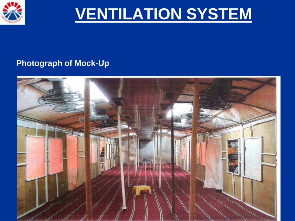
Photograph of Mock-Up
VENTILATION SYSTEM


The ventilation provided in Mumbai Sub-Urban Coaches was
a non standard and with such a large numbers
traveling in each coach, was a difficult problem to
solve. In the new EMU coaches procured under MUTP
project this problem was technically approached by
using following-
(a) Correct Standard Applicable
(b) Collection of accurate data
(c) Correct calculations of requirements
(d) Development of Mock-up to prove the design
(e) Manufacture of Ventilation units using reliable sub-systems.
(f) Extensive field Trials

Contribution to prevention of global warming
due to saving of Electric energy

Existing DC EMUs design details of
power circuit and brake system
• Power circuit The present design of EMU rakes draws electrical power from
OHE at 1500V DC, which is fed to four DC traction motors of 210
kW capacity. The control of speed of traction motors is through
resistance control, i.e. current is reduced or increased by
resistances.

• Present Brake System The braking of rakes is through friction braking using tread
brake system in the existing EMU’s.
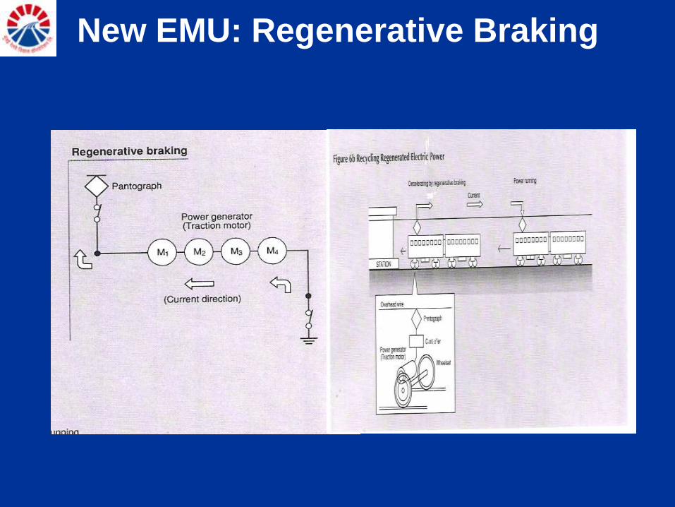
New EMU: Regenerative Braking

Improving Energy Efficiency
(a) DC EMU System (present)
(i) Holding of rakes :
Central Railway : 132.6 (9 car)
Western Railway : 94.6 ( 9car)
Total : 227.3 (9-car) (190 DC EMU +
37.3 AC/DC EMU rakes)
(ii) Energy consumption per DC 9 car rake per year is 2716406 Kwh
Improving Energy Efficiency
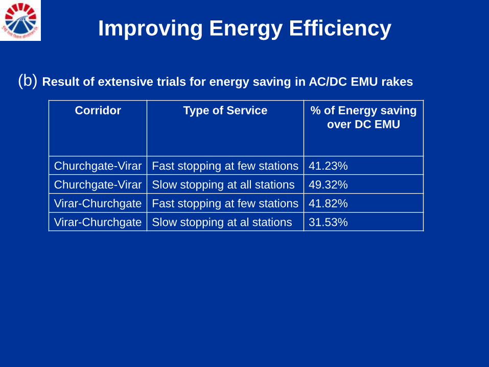
(b) Result of extensive trials for energy saving in AC/DC EMU rakes
Corridor Type of Service % of Energy saving
over DC EMU
Churchgate-Virar Fast stopping at few stations 41.23%
Churchgate-Virar Slow stopping at all stations 49.32%
Virar-Churchgate Fast stopping at few stations 41.82%
Virar-Churchgate Slow stopping at al stations 31.53%

Improving Energy Efficiency (c) AC/DC new technology EMU rakes
• As mentioned above, with the use of regenerative braking there will be a saving of
40% of electrical energy. By the end of first phase of MUTP, 190 new technology
EMU rakes would be available in Mumbai Suburban Railway System.
• Conventional DC EMU rake consumes 2.7 million units of energy every year/rake
and new technology EMU rake consumes 1.6 million units of energy every year/rake
for providing the same services. Thus with 190 EMU rakes after MUTP Phase I,
there would be a saving of 209 million electrical units of energy per year.
• After MUTP Ph – II the holding of rakes would be 346, 9 car and total saving would
be 380.6 Million units of Electrical Energy.
• With per unit cost @ Rs. 4, the financial savings would be INR 836 million per year
after MUTP – I and INR 1522.4 Million per year after MUTP Ph - II. Even if a
conservative estimate of 30% saving in Energy is considered, it will result in INR
1141 Million savings per year.

Benefits
Coal 4.6 x 10⁸ Kg.
LPG 14.26 x 10⁸ Ltr.
Crude Oil 21.46 x 10⁸ Ltr.
Natural Gas 21.6 x 10⁸ m3.
(a) Reduction in fuel consumption / year (Depending upon
Power Plant are anticipated as follows):-
(b) Reductions in Pollution:- By saving 20 Cr. units of power following will
be reduction in pollution per year (for Coal based Power Plants).
CO2 2.092 x 10⁸ Kg.
SO2 18 x 108 gm.
SPM 5 x 10⁸ gm
Soot Carbon 0.2 x 10⁸ gm
NO 20 x 108 gm
Reduction of CO2 according to KYOTO
Protocol is our commitment.
• Mumbai will receive 3 phase new technology EMU rakes with regenerative braking.
• Introduction of this technology would save about 20 crore units of energy every year
• For each unit of energy produced in a thermal power plant, 1 kg of carbon dioxide is produced.
• Thus, on account of this project there would be a reduction of approximately 2 lakh tones of carbon dioxide emission every year.
• This will qualify for Carbon Credits

Carbon Credits
• A project has been undertaken with World Bank to obtain Carbon Credits on account of this huge reduction in emission.
• The Project Idea Note for this project has already been approved by the World Bank and detailed work will start shortly.
• World Bank has approved and registered this project.
• This is a first project registered for transport sector.

Other environment friendly features of
New technology rakes • DC traction motor is replaced by 3 phase AC traction motor.
– Carbon brushes used in DC traction motors and DC fans. Total 4 lakh carbon
brushes per year will not be required.
• 110V DC carbon type fans have been replaced by 110V AC fans.
– Mica used in commutator of DC traction motor and DC fans.
• Oil lubricated suspension bearings have been replaced by axle mounted roller bearings.
– Mineral oil based lubricants for suspension bearing of DC traction motors. Total
85,000 litre of oil per year will not be required.
• By introducing electrical regenerative braking use of asbestos brake block for mechanical brakes reduced to 90%.
– Ferro asbestos brake blocks. Total 1.25 lakh brake blocks per year will not be
required.
It is seen that 380.6 Million units of Electrical energy will be saved per year by EMU’s and 62.6 Million units of Electrical Power will be saved per year due to 1500 V DC to 25kV AC conversion. On suburban section alone 443 Million units will be saved on completion of MUTP Ph-II. In monetary terms it will be INR 1772 Million (@ Rs 4/unit) per year. In addition, saving on account of deploying energy efficient High Power rated Electric locomotive vice D.C. Electric Locomotive on main line upto Pune and Igatpuri on C.Rly. and Virar on W.Rly. will also be considerable.

Website:www.mrvc.indianrail.gov.in