Embed Size (px)
Citation preview
THE SCIENCE OF A PURE ENVIRONMENTCertified ISO9001
June 2015
Via Pietro Nenni, 15 - 27058 – VOGHERA – ITALYTel. +39 0383 3371 – Fax +39 0383 369052
E-mail: [email protected]
Presentation ofWet Flue Gas Desulphurisation Technology

THE SCIENCE OF A PURE ENVIRONMENTCertified ISO9001
June 2015
INTRODUCTION TO IDRECO WFGD TECHNOLOGY
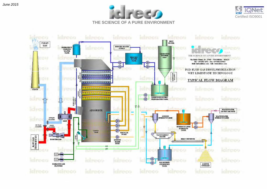
Idreco WFGD (Wet Flue Gas Desulphurisation) technology is based on the wet limestone absorption method withis based on the wet limestone absorption method with production of gypsum.
A typical flow diagram of a baseline wet FGD system is shown in the next slide.
THE SCIENCE OF A PURE ENVIRONMENTCertified ISO9001
June 2015
THE SCIENCE OF A PURE ENVIRONMENTCertified ISO9001
June 2015
INTRODUCTION TO IDRECO WFGD TECHNOLOGY
SO2-containing flue gas contacts alkaline slurry in a counter-flow vertically oriented open spray towerabsorber.
Limestone slurry is prepared mixing fine limestone powder with water in a slurry preparation tank SorbentLimestone slurry is prepared mixing fine limestone powder with water in a slurry preparation tank. Sorbentslurry from this tank is then pumped into the absorber reaction tank.The absorber is a counter-flow tower with flue gas flowing upwards, while limestone slurry is sprayeddownwards by an array of spray nozzles. In the absorber, SO2 is removed by both sorption and reactionwith the slurry.
Reactions initiated in the absorber are completed in the “absorber sump” working as a reaction tank, whichprovides retention time for finely ground limestone particles to dissolve and to react with the dissolved SO2provides retention time for finely ground limestone particles to dissolve and to react with the dissolved SO2and to produce gypsum by means of air addition.

THE SCIENCE OF A PURE ENVIRONMENTCertified ISO9001
June 2015
ABSORBER DESCRIPTION
The absorber consists of a vertical cylindrical vessel with flue gas inletThe absorber consists of a vertical cylindrical vessel, with flue gas inletand outlet openings.
The slurry in the sump consists of an aqueous solution of dissolved saltsin which approximately 12 to 20 wt% solids are suspended. In order tokeep these solids suspended in the slurry, the sump is provided with sideentry agitators.
The part of the absorber between the gas inlet and gas outlet is called‘’the gas section" which may be subdivided in "the spray section" and in"the mist eliminator section". The part of the absorber below the gasinlet contains the absorber slurry and is called "the sump".

THE SCIENCE OF A PURE ENVIRONMENTCertified ISO9001
June 2015
In the SPRAY SECTION, the flue gas to be treated is brought in intimate contact with a fine spray of slurry droplets, as produced by the slurry spray banks. The acid components, like SO2, HCl and HF are absorbed t l t d i th l d l t d t ith th li t t i th lto a large extend in the slurry droplets and react with the limestone present in the slurry.
Above the spray section, the MIST ELIMINATOR SECTION is installed. This section is equipped with a two-stage mist eliminator. The lower mist eliminator stage is a coarse separator, provided with a relatively l di t b t th bl d f th ti f th j t f th t i d l ti llarge distance between the blades, for the separation of the major part of the entrained, relatively coarse slurry droplets from the ascending flue gas flow. The upper mist eliminator stage is a fine separator, provided with a smaller distance between the blades for the separation of the fine slurry droplets and mist eliminator wash water droplets from the ascending flue gas flow. The droplets, separated from the gas flow p g g p , p gcoagulate to large droplets, which drip from the lower edges of the mist eliminator blades and fall downwards to the absorber sump.
The SUMP OF THE ABSORBER has many functions:y
- Completion of reaction of limestone with acid components.
- Conversion of initially formed sulphite to sulphate by forced oxidation.
- Provision of enough time for limestone dissolution.
- Crystallization of gypsum from the supersaturated solution.
P i i f id ti i d t bl ffi i t th f t l- Provision of residence time in order to enable sufficient growth of gypsum crystals.
- Provision of buffer volume of liquids and solids in order to stabilize the operation of the absorber during fast changes in process parameters, such as: Flue gas flow / Flue gas temperature / SO2 inlet concentration.

THE SCIENCE OF A PURE ENVIRONMENTCertified ISO9001
June 2015
ABSORBER CHEMISTRYThe overall chemical reaction between gaseous SO2 from the flue gases with an aqueous suspension ofg 2 g q pCaCO3 and O2 from oxidation air to solid gypsum crystals can be described as:
SO2 (g) + CaCO3 (s) + ½O2 (g) + 2H2O (l) CaSO4 . 2H2O (s) + CO2 ( g)
This overall reaction is the result of many intermediate reactions, such as:
a. Formation of SO3 ions in the slurry water phase:3 y pSO2 (g) + H2O (l) SO3
2- + 2H+ (1)
b. Conversion of SO3 ions to SO4 ions by oxidation:SO 2- + ½O (g) SO 2- (2)SO3
2- + ½O2 (g) SO42- (2)
c. Dissolution of limestone in the slurry water phase:CaCO3 (s) + H2O (l) Ca2+ + HCO3
- + OH- (3)3 ( ) 2 ( ) 3 ( )
d. Crystallization of gypsum from the solution:Ca2+ + SO4
2- + 2H2O CaSO4.2H2O (s) (4)
e. Neutralization of hydrogen ions by bicarbonate and hydroxyl ions:2H+ + HCO3
- + OH- CO2 (g) + 2H2O (l) (5)

THE SCIENCE OF A PURE ENVIRONMENTCertified ISO9001
June 2015
ABSORBER CHEMISTRY
The other acid gas components HCl and HF react likewise with the limestone:The other acid gas components HCl and HF react likewise with the limestone:
2HCl + CaCO3 Ca2+ + 2Cl- + CO2 + H2O (6)2HF + CaC03 CaF2 (s) + CO2 + H2O (7)3 2 2 2
Most of the HCl, present in the flue gas, is absorbed in the absorber recycle slurry and forms the soluble salt CaCl2 and isthe cause of the chloride level in the absorber slurry. In order to prevent high chloride levels in the absorber, an absorberpurge flow is required to remove the absorbed chlorides from the system.p g q yMost of the HF, present in the flue gas is absorbed in the absorber recycle slurry and reacts with the limestone to CaF2,which is practically insoluble. This component leaves the absorber together with the gypsum and forms a minor constituentof the final gypsum product.The absorber is not only an efficient scrubber for acid gases, also solid particles (fly ash) present in the flue gas, arey g , p ( y ) p g ,removed to a large extend. The fly ash, removed from the flue gases, leaves the absorber with the gypsum and is also aconstituent of the final gypsum product, lowering its purity.From the intermediate reactions (1), (3) and (5) it can be concluded that the pH value of the absorber slurry is animportant factor for the efficiency of acid gas removal.p y gAccording to reaction (1), H+ ions are formed during the absorption of acid gases like SO2, HCl and HF. An increased H+
ion concentration in the absorber slurry corresponds to lower pH values and will tend to shift the equilibrium of reaction(1) to the left, corresponding to a decreased ability of the slurry to absorb acid gases, resulting in a decrease of removalefficiency.yIn order to maintain a high degree of removal efficiency, the H+ ions must be quickly neutralized by an equivalent amountof alkalinity according to reaction (5).

THE SCIENCE OF A PURE ENVIRONMENTCertified ISO9001
June 2015
ABSORBER CHEMISTRY
This alkalinity is produced by the dissolution of limestone according to reaction (3) The dissolution ofThis alkalinity is produced by the dissolution of limestone according to reaction (3). The dissolution oflimestone in water is a slow process, it depends on the following 3 factors:
- Particle size of the solid limestone particles.A finely ground limestone dissolves faster than a coarse ground limestone.
- Reactivity of the limestone. A reactive limestone dissolves faster than an un-reactive limestone.- pH value of the absorber slurry. A lower pH value leads to a faster limestone dissolution.
From the above information, the following can be concluded:- A high pH value is beneficial for the acid gas removal efficiency, but detrimental to the limestonedissolution rate- A low pH value is detrimental to the acid gas removal efficiency, but beneficial for the limestonedissolution rate
Experience has shown that an absorber slurry pH value of approximately 5 7 is the optimum pH valueExperience has shown, that an absorber slurry pH value of approximately 5.7 is the optimum pH value,resulting in a sufficiently high limestone dissolution rate and high acid gas removal efficiency.
The limestone slurry supply to each absorber is controlled in such a way, that the pH value of the recycledslurry remains approximately constant at normal operating conditions.

THE SCIENCE OF A PURE ENVIRONMENTCertified ISO9001
June 2015
ABSORBER OXIDATION AIR INJECTION SYSTEM
As can be concluded from intermediate reaction (2), oxygen isrequired for the oxidation of sulphite ions to sulphate ions.Although a certain amount of natural oxidation can beattributed to the oxygen present in the flue gas, the sulphiteyg p g , poxidation occurs mainly in the absorber sump.In order to obtain nearly 100% oxidation of sulphite tosulphate, each absorber is provided with an oxidation airinjection system for the injection of a certain flow of oxidationj y jair, supplied from a compressor system. The oxidation air isevenly distributed across the absorber cross-sectional area byan air injection system, consisting of: an air sparger bank ofhorizontally mounted pipes with drilled holes in the pipe side
BY AIR SPARGERS BY AIR LANCES
y p p p por a number of air lances installed in front of each agitator.
The fresh limestone slurry is added to the sump of theabsorber. N l lThe pH value in the zone above the air sparger system is lowerthan the pH value of the absorber slurry in the lower part ofthe sump. A low pH value in the zone above the air injectionsystem (the oxidation zone) promotes the oxidation of sulphite
Normal lances
y ( ) p pto sulphate.
Forced oxidationAir spargers layout

THE SCIENCE OF A PURE ENVIRONMENTCertified ISO9001
June 2015
ABSORBER OXIDATION AIR INJECTION SYSTEM
The oxidation air is supplied by an oxidation air headerlocated above the liquid level in the sump. From this header,separate air pipes run vertically downwards outside theabsorber to the level of the air injection system. The airinjection pipes are externally connected to the vertical airpipes. The hot compressed air is cooled down by means of acooling water nozzles installed into the air header.
In case of use of air sparger system, each sparger pipe isprovided with a shut-off valve and a flushing connection, sothat each pipe can be flushed during normal operation.
In case of use of air lances system the flushing is notnecessary because experience has shown that air pipeflushing is hardly required between absorber maintenanceshut downs.
The liquid height above the air sparger system is derivedfrom the required sump oxidation volume at the maximummass flow of SO2 to be removed from the flue gases.

THE SCIENCE OF A PURE ENVIRONMENTCertified ISO9001
June 2015
ABSORBER RECYCLE SYSTEMThe absorber is provided with slurry recycle pumps, each connected to its own slurry spray bank.E h ti id i t d t th b b i ti i ith t t d h t ff l dEach pump suction side is connected to the absorber sump via a suction pipe with a motor operated shut-off valve anda suction strainer. Each pump discharge side is connected to a spray bank via a pump discharge pipe.
The pump suction strainers prevent entrance of largergypsum lumps in the spray bank system which mightlead to clogged nozzles.
Each strainer is cleaned by the back flow of slurrywhen a recycle pump is taken out of operation.
Thi h ld b d t l i t l (This should be done at regular intervals (e.g. once aweek), also to check the proper operation of all pumpsafety devices. Each pump is provided with anautomatically operating drain- and flushing system.
THE SCIENCE OF A PURE ENVIRONMENTCertified ISO9001
June 2015
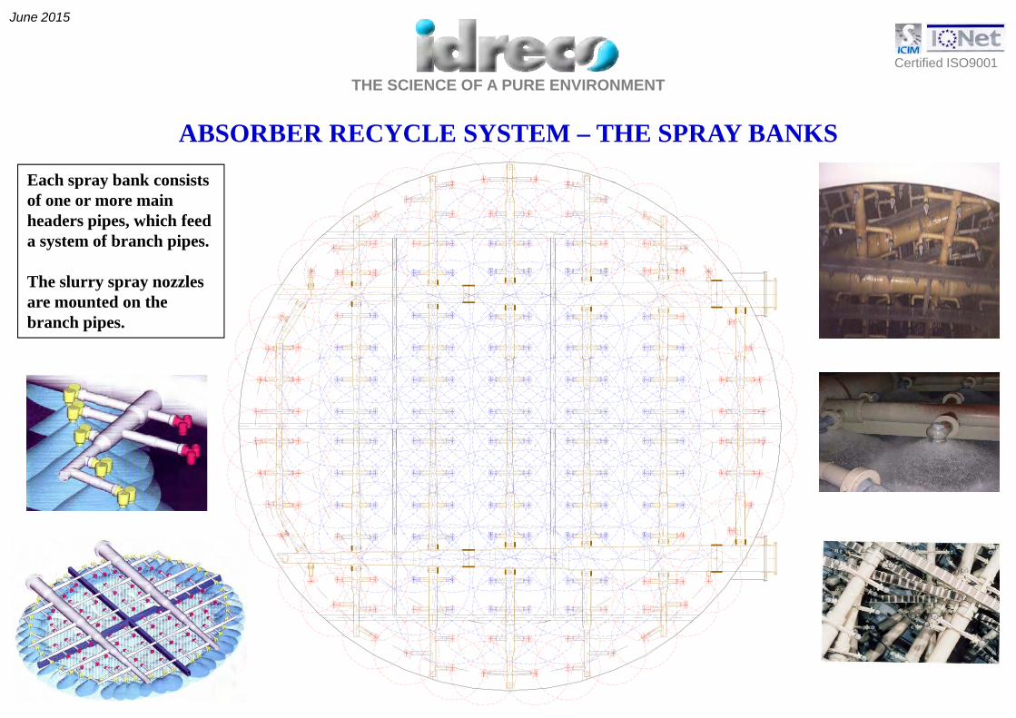
ABSORBER RECYCLE SYSTEM – THE SPRAY BANKS
Each spray bank consistsEach spray bank consists of one or more main headers pipes, which feed a system of branch pipes.
The slurry spray nozzles are mounted on the branch pipes.
THE SCIENCE OF A PURE ENVIRONMENTCertified ISO9001
June 2015
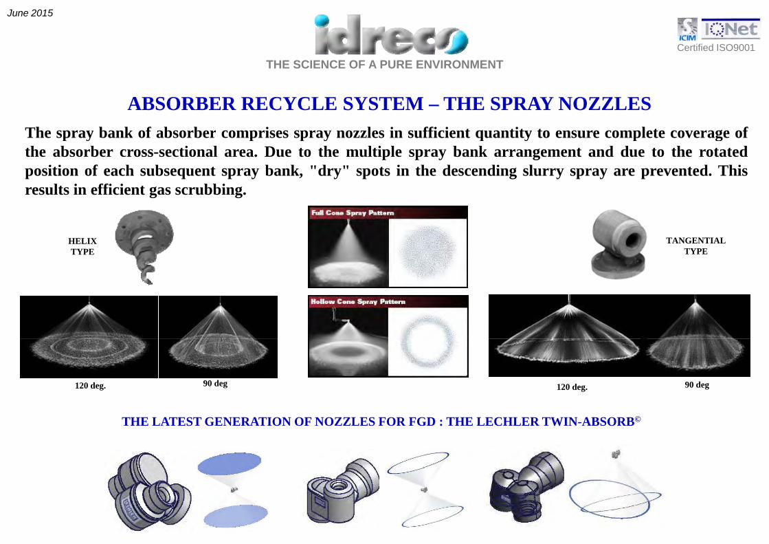
ABSORBER RECYCLE SYSTEM – THE SPRAY NOZZLESThe spray bank of absorber comprises spray nozzles in sufficient quantity to ensure complete coverage ofp y p p y q y p gthe absorber cross-sectional area. Due to the multiple spray bank arrangement and due to the rotatedposition of each subsequent spray bank, "dry" spots in the descending slurry spray are prevented. Thisresults in efficient gas scrubbing.
HELIXTYPE
TANGENTIALTYPE
120 deg. 90 deg120 deg. 90 deg
THE LATEST GENERATION OF NOZZLES FOR FGD : THE LECHLER TWIN-ABSORB©

THE SCIENCE OF A PURE ENVIRONMENTCertified ISO9001
June 2015
ABSORBER MIST ELIMINATOR SYSTEMThe absorber is provided with two-stage misteliminator, in order to retain liquid droplets in theabsorber. These mist eliminator stages must becleaned regularly in order to prevent clogging dueto deposition of solid material as gypsum and fly-ash.ash.Cleaning is effected by water wash via a spray banksystem: the lower mist eliminator is provided with 2(two) spray banks, 1 (one) below and 1 (one) abovethis mist eliminator, while the upper mist eliminatoris usually provided with only 1 spray bank belowis usually provided with only 1 spray bank belowthis mist eliminator.Each spray bank consists of a number of parallelpipes, provided with spray nozzles on equaldistances. The nozzle pattern ensures completecoverage of the mist eliminator surfaces. Each spraypipe of a spray bank is provided with a pneumaticcylinder operated on/off valve, and only 1 (one)spray pipe is activated at the same time. All on/offvalves are connected to a programmable timerp gmechanism, enabling adjustment of spray pipeactivation sequence, and the duration of the spraytime.Each spray pipe is activated for approximately 2minutes then its on/off valve is closed again After aminutes, then its on/off valve is closed again. After acertain pause time, the next on/off valve, accordingto the sequence, is opened for 2 minutes. Thissystem cleans the mist eliminator surfaces insections with a high intensity of wash water.

THE SCIENCE OF A PURE ENVIRONMENTCertified ISO9001
June 2015
ABSORBER MIST ELIMINATOR SYSTEM
The mist eliminator wash water is also the absorber make-up waterwhich is lost by the following causes:- Evaporation of water from the absorber slurry due to the
cooling and saturation with water vapour of the fluegases during the passage of the absorbergases during the passage of the absorber.
- Absorber purge flow for the removal of chlorides.-Crystal water and the residual moisture in the dewateredgypsum product
- Entrainment of liquid water by the clean gases leavingth b b lth h thi l i llthe absorber, although this loss is very small.
The absorber is also supplied with water from the following sources:- Water in the limestone slurry fed to the absorber- Vacuum belt filter cake wash water and basket rinse
water which is fed to the absorbers producing productgypsum via the circuit water system.
The losses are much more than the supplies; therefore make-up water isto be supplied to the absorber in order to maintain the water balance.This make-up water is supplied as mist eliminator wash water.This make up water is supplied as mist eliminator wash water.The absorber make-up water flow (mist eliminator wash water flow) iscontrolled by the absorber level control system. This level control systemadjusts the pause time between the subsequent activations of the misteliminator spray bank pipes.At hi h b il l d d hi h fl t t k tAt high boiler loads and high flue gas temperatures more make-up wateris required, resulting in reduced pause times in the mist eliminator washcycle; low boiler loads and low flue gas temperatures will result inincreased pause times.

THE SCIENCE OF A PURE ENVIRONMENTCertified ISO9001
June 2015
ABSORBER BLEED & GYPSUM CYCLONES
The absorber removes SO2 from the flue gases andproduces gypsum. Obviously, the produced gypsump gyp y, p gypmust be removed from the absorber, otherwise thegypsum would accumulate in the absorber, leading toan absorber slurry with a high concentration ofsuspended solids. The normal average suspendedp g psolids concentration in the absorber slurry is about15.0 wt%, but slightly lower or higher concentrationsdo not interfere with the proper absorber operation.
It is the task of the absorber bleed system to removethe actual gypsum production in each absorber.The bleed system consists essentially of an absorberbleed pump and a gypsum cyclone battery, supplied
The system operates asdescribed below:p p gyp y y pp
with absorber slurry by the absorber bleed pump.This system is operated at a fixed capacity, which islarger than the maximum gypsum production of theabsorber. The gypsum suspension flows through a
The gypsum cyclone battery comprises a multiple cyclonearrangement, complete with feed distributor and overflowcollector.
main ring. In case the hydrocyclones are not ready,the gypsum suspension is discharged back into theabsorber.
The cyclones are fed with absorber bleed at a constantpressure and hence at a more or less constant feed flow witha suspended solids concentration of approximately 15 wt%.

THE SCIENCE OF A PURE ENVIRONMENTCertified ISO9001
June 2015
ABSORBER BLEED & GYPSUM CYCLONESThe cyclones split the feed flow in a cyclone underflow with a
i i f i 0 %The function of the gypsum cyclone battery is 3-fold:
suspended solids concentration of approximately 50 wt%and a cyclone overflow with a suspended solids concentrationof approximately 3,5 wt%. The underflow of the cyclones iscollected in the gypsum slurry distribution tank and thenflows to the vacuum belt filters
- Increase of suspended solids concentration in the absorberslurry to the proper vacuum belt filter feed concentration.
Classification of the suspended solids in the absorber feedflows to the vacuum belt filters.The cyclone overflow is collected in the gypsumhydrocyclones overflow tank and most of it flows back to theabsorber. A part of this collected overflow is pumped to the2nd hydrocyclone. The overflow of this hydrocyclone,
- Classification of the suspended solids in the absorber feedslurry. The coarser, heavier particles leave the cyclones with theunderflow, while the smaller, lighter particles leave the cycloneswith the overflow, which is returned to the absorber for furthergrowth of the small particles.y y y y ,
containing a small quantity of solids, is sent to a waste watertreatment plant for the purpose of discharging fly ash, inertsof the limestone and chlorides; the underflow, containinglarger particles of limestone and gypsum, is recovered to the
g p
- Separation of the small limestone particles still present in theabsorber bleed slurry.These fines are returned with the overflow to the absorber for
absorbers. further utilization in the desulphurisation process; thelimestone concentration in the concentrated slurry to betransferred to the gypsum dewatering is therefore lower thanin the absorber slurry.
This improves both the purity of the final gypsum product andlimestone utilization.

THE SCIENCE OF A PURE ENVIRONMENTCertified ISO9001
June 2015
GYPSUM DEWATERING
The underflow coming from the first hydrocyclone is collected by gravity to the gypsumslurry distribution tank and then to two vacuum belt filters where gypsum is dewatered toa moisture content less than 10 % mass.Gypsum washing is done in the vacuum belt filters with addition of process water.The filtrate of the vacuum belt flows to the recovered suspension tank which supplies theabsorber with additional water.Also use of vertical centrifuges is possible in specific cases to have gypsum with less
i t t t th th d d b th b lt filtmoisture content than the one produced by the vacuum belt filters.
The dried gypsum is then stored in gypsum silos equipped with special extraction systemsor in a storehouse.From the above storages the dried gypsum is finally loaded to trucks for sales.
THE SCIENCE OF A PURE ENVIRONMENTCertified ISO9001
June 2015
LIMESTONE PREPARATION
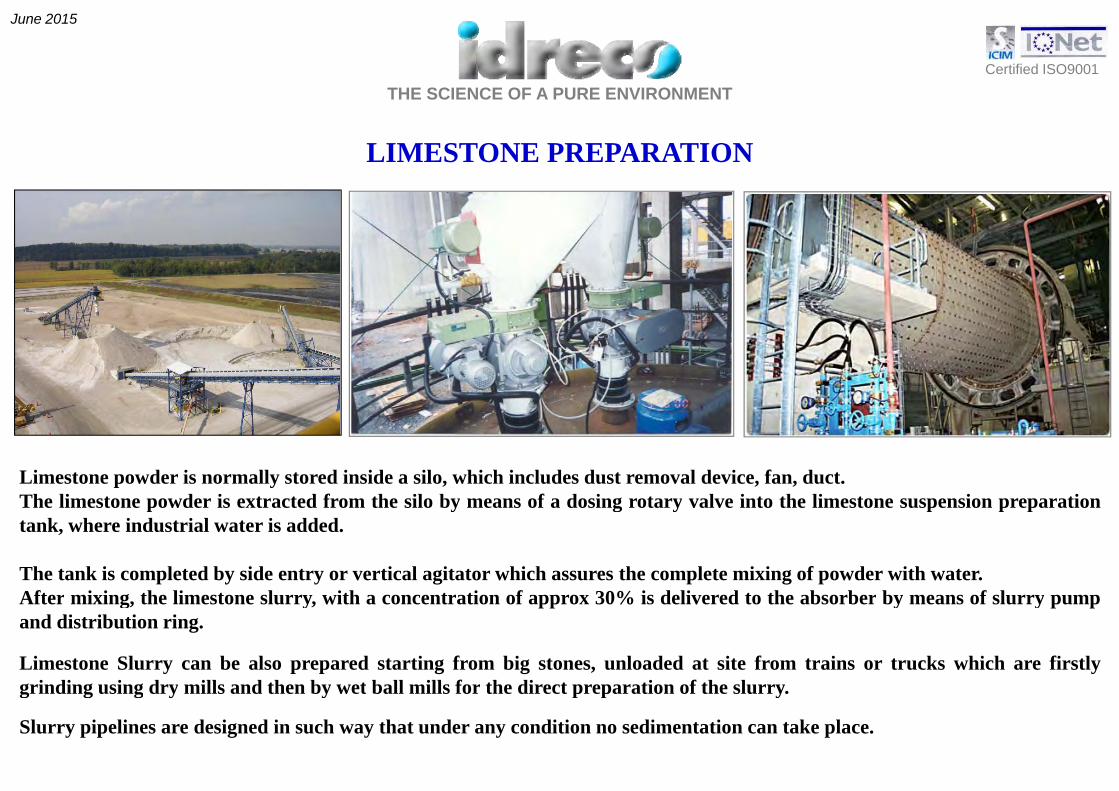
Limestone powder is normally stored inside a silo, which includes dust removal device, fan, duct.The limestone powder is extracted from the silo by means of a dosing rotary valve into the limestone suspension preparationtank, where industrial water is added.
The tank is completed by side entry or vertical agitator which assures the complete mixing of powder with water.After mixing, the limestone slurry, with a concentration of approx 30% is delivered to the absorber by means of slurry pumpand distribution ring.
Limestone Slurry can be also prepared starting from big stones, unloaded at site from trains or trucks which are firstlygrinding using dry mills and then by wet ball mills for the direct preparation of the slurrygrinding using dry mills and then by wet ball mills for the direct preparation of the slurry.
Slurry pipelines are designed in such way that under any condition no sedimentation can take place.

THE SCIENCE OF A PURE ENVIRONMENTCertified ISO9001
June 2015
LIMESTONE SLURRY TRANSPORTATIONDistance = 1200 m. Shajiao C 3x660MW Units

THE SCIENCE OF A PURE ENVIRONMENTCertified ISO9001
June 2015
HEAT EXCHANGER CONSIDERATIONS
ADVANTAGES AND DISADVANTAGESOF USING HEAT EXCHANGER
Flue gas heat exchanger is needed to increase the temperature of the treatedflue gas leaving the absorber before the gases are discharged to theatmosphere.
The main reasons to use flue gas reheat are the following:- to improve the dispersion of pollutants into the atmosphere (higher)- clean gas temperature increases the plume’s buoyancy, as a result
of a higher plume rise and better dispersion of flue gasof a higher plume rise and better dispersion of flue gas.- to reduce the visible plume (reduction in the plume visibility dependsalso on ambient temperature and wind conditions).
- to avoid liquid droplet rainout from the stack (increasing clean gastemperature promotes evaporation of small droplets at the demisteroutlet and minimizes condensation on the duct walls)outlet and minimizes condensation on the duct walls).
- to avoid corrosion problems on downstream materials.
The most used system to reheat the clean gases is the regenerative reheatsystem (Liungstroem), which removes part of the heat from the raw flue gasupstream of absorber and transfer that energy to the treated flue gas. Heatupstream of absorber and transfer that energy to the treated flue gas. Heatexchangers reduce the temperature of the flue gas entering the absorber andreduce both the adiabatic saturation temperature of the flue gas and the rateof evaporation in the absorber; therefore the water consumption is reduced.
The main disadvantage in using heat exchanger is a pressure drop increasingg g g p p gand consequently a higher booster fan power consumption.
THE SCIENCE OF A PURE ENVIRONMENTCertified ISO9001
June 2015
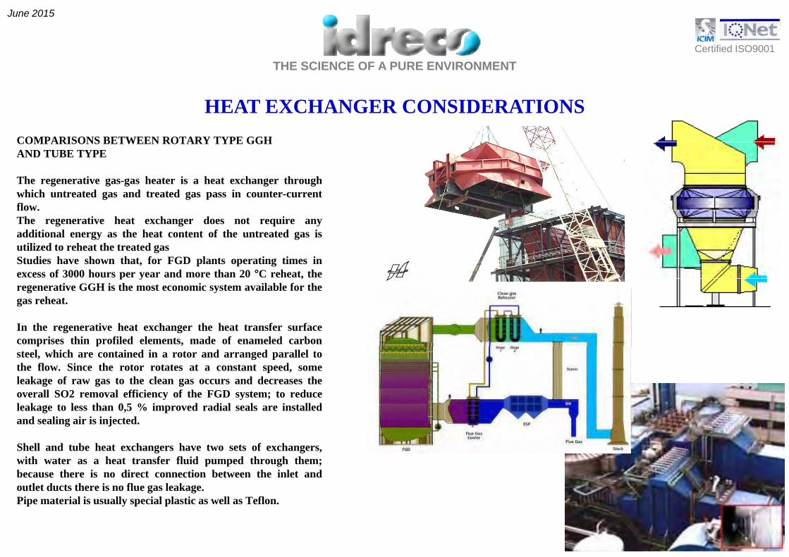
HEAT EXCHANGER CONSIDERATIONSCOMPARISONS BETWEEN ROTARY TYPE GGHCOMPARISONS BETWEEN ROTARY TYPE GGHAND TUBE TYPE
The regenerative gas-gas heater is a heat exchanger throughwhich untreated gas and treated gas pass in counter-currentflow.flow.The regenerative heat exchanger does not require anyadditional energy as the heat content of the untreated gas isutilized to reheat the treated gasStudies have shown that, for FGD plants operating times inexcess of 3000 hours per year and more than 20 °C reheat, thep y ,regenerative GGH is the most economic system available for thegas reheat.
In the regenerative heat exchanger the heat transfer surfacecomprises thin profiled elements, made of enameled carbonsteel, which are contained in a rotor and arranged parallel tothe flow. Since the rotor rotates at a constant speed, someleakage of raw gas to the clean gas occurs and decreases theoverall SO2 removal efficiency of the FGD system; to reduceleakage to less than 0,5 % improved radial seals are installedand sealing air is injected.
Shell and tube heat exchangers have two sets of exchangers,with water as a heat transfer fluid pumped through them;because there is no direct connection between the inlet andoutlet ducts there is no flue gas leakage.Pipe material is usually special plastic as well as Teflon.

THE SCIENCE OF A PURE ENVIRONMENTCertified ISO9001
June 2015
HEAT EXCHANGER CONSIDERATIONS
Comparison betweenThe two types of exchanger
REGENERATIVE GGH SHELL AND TUBE EXCHANGER
OVERALL DIMENSIONS More compact Less compact
LEAKAGE Low None
PRICE Lower Higherg
FLUID COMPOSITION None Water
RAW GAS PRESSURE 4 - 5 4 - 5DROP (mbar) 4 5 4 5
CLEAN GAS PRESSURE DROP (mbar 4 - 5 4 - 5
Pi t t 2 h tEQUIPMENT REQUIREMENTS GGH only
Pipes to connect 2 heat exchangers plus circulating water
pumps and chillers

THE SCIENCE OF A PURE ENVIRONMENTCertified ISO9001
June 2015
HARMONIC UNIFORMITY BETWEEN THE HIGHER DESULPHURIZATION EFFICIENCY AND LOWER ENERGY CONSUMPTION
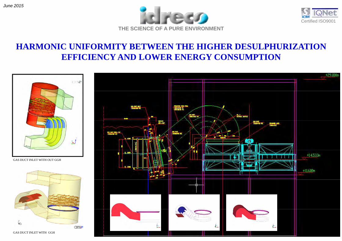
Fluid dynamics computation allows to optimize the pabsorber and gas duct size and shape, so that gas pressure drops along the FGD plant are minimized. Therefore, booster fan power consumption is also optimized.
The number of recycle pumpsThe number of recycle pumps is selected to minimize the power consumption to operate in function of the effective SO2 amount in the absorber inlet raw gases.
THE SCIENCE OF A PURE ENVIRONMENTCertified ISO9001
June 2015
HARMONIC UNIFORMITY BETWEEN THE HIGHER DESULPHURIZATION EFFICIENCY AND LOWER ENERGY CONSUMPTION
GAS DUCT INLET WITH OUT GGH
GAS DUCT INLET WITH GGH

THE SCIENCE OF A PURE ENVIRONMENTCertified ISO9001
June 2015
DESIGN CHARACTERISTICS OF THE ABSORBERS
100% DESIGNED WITHFLOW FIELD COMPUTERDYNAMIC CALCULATION
THE SCIENCE OF A PURE ENVIRONMENTCertified ISO9001
June 2015
HEIGHT OF ABSORBER
DESIGN CHARACTERISTICS OF THE ABSORBERS
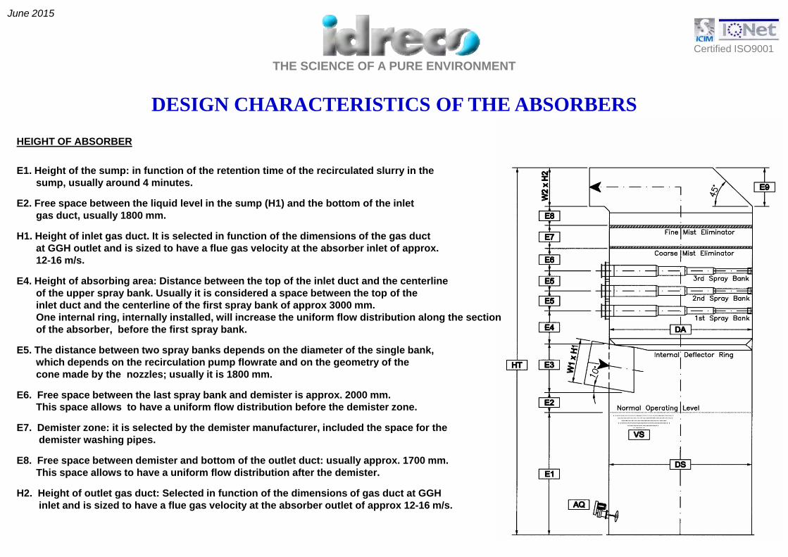
HEIGHT OF ABSORBER
E1. Height of the sump: in function of the retention time of the recirculated slurry in thesump, usually around 4 minutes.
E2. Free space between the liquid level in the sump (H1) and the bottom of the inletgas duct, usually 1800 mm.
H1. Height of inlet gas duct. It is selected in function of the dimensions of the gas ductat GGH outlet and is sized to have a flue gas velocity at the absorber inlet of approx.12-16 m/s.
E4 H i ht f b bi Di t b t th t f th i l t d t d th t liE4. Height of absorbing area: Distance between the top of the inlet duct and the centerlineof the upper spray bank. Usually it is considered a space between the top of theinlet duct and the centerline of the first spray bank of approx 3000 mm.One internal ring, internally installed, will increase the uniform flow distribution along the sectionof the absorber, before the first spray bank.
E5 Th di t b t t b k d d th di t f th i l b kE5. The distance between two spray banks depends on the diameter of the single bank,which depends on the recirculation pump flowrate and on the geometry of thecone made by the nozzles; usually it is 1800 mm.
E6. Free space between the last spray bank and demister is approx. 2000 mm.This space allows to have a uniform flow distribution before the demister zone.
E7. Demister zone: it is selected by the demister manufacturer, included the space for thedemister washing pipes.
E8. Free space between demister and bottom of the outlet duct: usually approx. 1700 mm.This space allows to have a uniform flow distribution after the demister.
H2. Height of outlet gas duct: Selected in function of the dimensions of gas duct at GGHinlet and is sized to have a flue gas velocity at the absorber outlet of approx 12-16 m/s.

THE SCIENCE OF A PURE ENVIRONMENTCertified ISO9001
June 2015
DESIGN CHARACTERISTICS OF THE ABSORBERS
SPRAY NOZZLESIdreco technology uses tangential nozzles which produce a full or hollow cone cone spray patterns.The fluid full cone shape allows to cover a high specific surface and to produce a large number of very finedroplets in order to reach an elevated liquid surface area for improving the gas/liquid mass transfer.Droplet mean diameters for the slurry spray nozzle are typically between 2000 and 2500 m; this valueallows the perfect contact between raw gases and slurry and optimizes liquid to gas ratio.The nozzle working pressure is around 0,5 – 0,7 barg of liquid column, so that the recycle pump head andpower absorption can be optimized.
Idreco has specifically designed the distribution of nozzle inside the absorber so that a complete spraycoverage is achieved.
pH VALUETypical operating pH value is around 5 – 6. Optimum value is 5.7
LIQUID GAS RATIOLiquid gas ratio amount expresses the surface area of droplets which come in contact with flue gas.The selection of L/G ratio depends mainly on the following parameters:- SO2 concentration in the flue gases at the absorber inlet- SO2 requested removal efficiency.
C /S RATIOCa/S RATIOLimestone utilization is very high. Limestone consumption can be assumed to be 2 – 3 % higher than thestoichiometric value.
100% DESIGNED WITHFLOW FIELD COMPUTERDYNAMIC CALCULATION

THE SCIENCE OF A PURE ENVIRONMENTCertified ISO9001
June 2015
OXIDATION AIR FLOW
DESIGN CHARACTERISTICS OF THE ABSORBERS
OXIDATION AIR FLOWOxidation air flow is calculated in function of the overall chemical reaction:
SO2 + CaCO3 + ½O2 + 2H2O 1CaSO4 . 2H2O + CO2
Th i ti f 2 3 t 3 ti th t i hi t i l Thi l l d d thThe air consumption can vary from 2,3 to 3 times the stoichiometric value. This value can also depend on therequested final gypsum quality.
SLURRY CONCENTRATIONSolids concentration in the slurry is typically maintained at 12 to 20 percent solids by weight. It is controlled byremoving a part of the slurry from the reaction tank for subsequent dewatering Proper solids concentration inremoving a part of the slurry from the reaction tank for subsequent dewatering. Proper solids concentration inthe slurry is necessary to ensure scale-free operation of the absorber. Correct solids retention time in thereaction tank is essential to achieving high utilization of limestone and maintaining correct handling anddewatering properties of solids.
VELOCITY PRESSURE TEMPERATURE100% DESIGNED WITHFLOW FIELD COMPUTERDYNAMIC CALCULATION

THE SCIENCE OF A PURE ENVIRONMENTCertified ISO9001
June 2015
Technical measures taken to assure the safe operation of the absorber
Emergency Cooling SystemEmergency cooling system is foreseen to cool the absorber inlet flue gas in case any emergency situation can occur, such as a failure of the electricalsupply (slurry recycle to spray banks is prevented) or a failure in the GGH rotation. Emergency cooling system is needed to avoid any damage totemperature sensitive absorber internals such as linings and mist eliminators blades.Emergency cooling system is designed according to the maximum possible inlet temperature for a timing of approx 5 minutes, time sufficient to open theby pass damper and close the raw gas and clean gas dampers.Emergency cooling system consists of emergency cooling tank, positioned in the upper part of the absorber, of relevant pipes and automatic valve, and aseries of spray nozzles installed inside the absorber inlet duct. Spray nozzle displacement is opportunely studied to achieve an uniform distribution ofwater along the duct section.
Selection of absorber materialsAbsorber materials are selected to take into account the severe working conditions to which they are submitted.- Inlet gas duct is made of Hastelloy C 276.- Absorber can be either all internally rubber lined, or all glass flake lined, or full metal.- Alternatively, rubber can be used in the lower part of the absorber (sump zone) whereas the absorbing zone can be either rubber lines,
metal lined by Hastelloy cladding or full metal.
Prevention against scalingScaling is avoided checking the correct solids concentration in the slurry in a range of 12 – 20% and then in the reaction tank which is located in thelower part of the sump. A series of agitators are located inside the sump and assure the perfect agitation of the slurry into the sump avoiding any solidssedimentation.Blowing air is injected inside the sump to promote controlled oxidation of calcium sulfites to calcium sulfate and to obtain rapid calcium sulfate crystalgrowth on seed crystals. Forced oxidation minimizes scaling in the absorber and also results in slurry that can be more easily dewatered.
Prevention against cloggingg gg gNozzle clogging cannot occur since liquid flow is counter current to gas flow. Usually, nozzle are tangential cone type which has free passage equal to 40mm. Alternatively spiral nozzles, with free passage equal or higher than 25 mm can be also used.Furthermore, into the absorber the suction zone of the recycle slurry pumps is provided of one screen with 20 mm diameter holes; this avoid to re-circulate solids with big dimensions to the spray nozzles.
THE SCIENCE OF A PURE ENVIRONMENTCertified ISO9001
June 2015
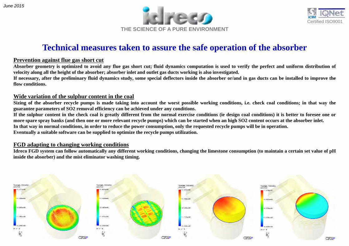
Prevention against flue gas short cut
Technical measures taken to assure the safe operation of the absorberg g
Absorber geometry is optimized to avoid any flue gas short cut; fluid dynamics computation is used to verify the perfect and uniform distribution ofvelocity along all the height of the absorber; absorber inlet and outlet gas ducts working is also investigated.If necessary, after the preliminary fluid dynamics study, some special deflectors inside the absorber or/and in gas ducts can be installed to improve theflow conditions.
Wide variation of the sulphur content in the coalSizing of the absorber recycle pumps is made taking into account the worst possible working conditions, i.e. check coal conditions; in that way theguarantee parameters of SO2 removal efficiency can be achieved under any conditions.If the sulphur content in the check coal is greatly different from the normal exercise conditions (ie design coal conditions) it is better to foresee one ormore spare spray banks (and then one or more relevant recycle pumps) which can be started when an high SO2 content occurs at the absorber inlet.p p y ( y p p ) gIn that way in normal conditions, in order to reduce the power consumption, only the requested recycle pumps will be in operation.Eventually a suitable software can be supplied to optimize the recycle pumps utilization.
FGD adapting to changing working conditionsIdreco FGD system can follow automatically any different working conditions, changing the limestone consumption (to maintain a certain set value of pHy y y g , g g p ( pinside the absorber) and the mist eliminator washing timing.

THE SCIENCE OF A PURE ENVIRONMENTCertified ISO9001
June 2015
THE ADVANTAGES OF IDRECO WET FGD TECHNOLOGY
High separation efficiency
Limestone consumption close to stoichiometric ratio
Reduced Space requirement resulting from compact construction
Scrubbing tower complete with integral absorption, oxidation, crystallizing and mist separator stage.
Plug proof scrubber construction No packing grids nor tray or other similar devices to increase Plug-proof scrubber construction. No packing grids, nor tray or other similar devices to increasethe contact surface between liquid and gas are foreseen in Idreco FGD technology.This solution avoids any encrusting during operation, therefore frequent and heavy maintenance isnot required.
Trouble free equipment start-ups and shut-downs
Complete gas desulphurisation within 10-15 minutes from equipment start-up
The system is very flexible and accepts quick increasing of gas flowrate and of SO2 inlet content.
Production of valuable gypsum ready for sales.
HIGH RELIABILITY BY INSTALLING A THOROUGLY PROVEN FGD DESIGN

THE SCIENCE OF A PURE ENVIRONMENTCertified ISO9001
June 2015
I-DeSOx© the proprietary software for the process calculationof Flue Gas Desulphurisation plants with IDRECO WFGD wet limestone/gypsum technology
Multilanguage Internet Web interface

THE SCIENCE OF A PURE ENVIRONMENTCertified ISO9001
June 2015
I-DeSOx© the proprietary software for the process calculationof Flue Gas Desulphurisation plants with IDRECO WFGD wet limestone/gypsum technology
User-friendly Process Data Input form

THE SCIENCE OF A PURE ENVIRONMENTCertified ISO9001
June 2015
I-DeSOx© the proprietary software for the process calculationof Flue Gas Desulphurisation plants with IDRECO WFGD wet limestone/gypsum technology
Database of all performed calculations
THE SCIENCE OF A PURE ENVIRONMENTCertified ISO9001
June 2015
I-DeSOx© the proprietary software for the process calculationof Flue Gas Desulphurisation plants with IDRECO WFGD wet limestone/gypsum technology
Automatic Report of Input Data

THE SCIENCE OF A PURE ENVIRONMENTCertified ISO9001
June 2015
I-DeSOx© the proprietary software for the process calculationof Flue Gas Desulphurisation plants with IDRECO WFGD wet limestone/gypsum technology
Automatic Report of Main Equipment Sizing
THE SCIENCE OF A PURE ENVIRONMENTCertified ISO9001
June 2015
I-DeSOx© the proprietary software for the process calculationof Flue Gas Desulphurisation plants with IDRECO WFGD wet limestone/gypsum technology
Automatic Report of Mass Balance Sheet

THE SCIENCE OF A PURE ENVIRONMENTCertified ISO9001
June 2015
Via Pietro Nenni, 15 - 27058 – VOGHERA – ITALYTel. +39 0383 3371 – Fax +39 0383 369052
E il i f @idE-mail: [email protected]
Thank you !Thank you !
STATE OF THE ART TECHNOLOGIES FORAIR POLLUTION CONTROL