Embed Size (px)
Citation preview

Presentation About Anatomy-Based Joint Models for Virtual
Humans SkeletonsPrepared By
Khloud Zain Al-Abdeen - 428220500
Najwa Al-Ghamdi - 427220110

Introduction• Introduction• Addressed Problem• Solution of this paper• Pseudo-code• Achievements of the Proposed Solution• Comparison between this model & other models• The weakness of this Model

Introduction
•The use of computer graphics in many applications was dramatically growing in the last decade, especially in area of medicine and virtual reality.
• Such applications are developed using human body models.
•The requirements of these models determine the degree of complexity and fidelity of these models to the human anatomy and the realism of movement.
Addressed Problem• The Previous models lack in the ability to
perform correct motion and need a complex control system to look like humans. And this is due to the simplification that the developers had been approached in building their models

Literature review
1. Hierarchy 3D (H3D) Model • By Boulic et al .• Specification
1. Each joint has only one rotational or translation DOF. I.e. building a joint of two DOFs, like a wrist, require creating of joints.
2. Each joint is associated with a matrix, which represents the relationship between this joint and its parent and the root joint of the model.

Literature review 2. Axis Position Joint (APJ) Model
• proposed by Zeltzer, and extended by Silva.• Specification
1. Each joint in this model has its own local reference frame (coordinate system) to define position and orientation of it, in means of its parent coordinate system in the body.
2. Each joint has several DOFs.3. A pointer to children is associated with each joint.4. "The position and orientation of any joint of the tree
can be obtained by composing the homogeneous transformation matrices that define the reference frames of each joint."

Literature review 3. Animal Articulated Skeleton • Specification
support muscles and simulated skin in a tree architecture
consist of segments that are linked through three rotational DOF joints, that has their own reference model
Note that the segment is a composition of bones muscles And skin.

Literature review
4. Spine and Torso Model • Developed by Monheit and Badler.• Specification
Virtual human torso is built using medical measurement data that are driven from the motion of every individual elements of the body such as vertebrae, muscles and ligaments, and the properties of bones and cartilaginous discs, with an easy way to control motion, suitable for ergonomics applications.

Literature review
5. Human Shoulder Model • By Maurel and Thalmann • Specification
based on the specula movement relative to the thorax
the hierarchical representation is not adapted
scapula is linked to the thorax by a 5 DOFs joint .
The other shoulder joints are 3 DOFs joints.
Specula
thorax

Literature review – criticism
1. Not realistic • The previous models proposed that
rotational DOF of a joint is able to rotate 360 degrees, which means that there are no constraint among the motion range
2. Lack of anatomic correctness • the displacement that occurred to the
rotation axis from its original position while rotation in some joints, was ignored.

Literature review – criticism
Lack of anatomic correctness

Literature review – criticism 3. Distortion in the movement
• Most of motion measurements were calculated for each joint and each DOF individually, with isolation of the other related joints' Impacts to the motion of that joint.
4. Models are monolithically structured▫ object-oriented (OO) modeling and UML
are recommended to overcome the negative consequences on using the monolithic architecture

Approach of this paper• Human body will be represented as a tree, each
node in the tree is a joint and the edges correspond to the body segment
• Every joint has a 4x4 LIM (Local Instance Matrix), which include the relationship between the parent and the child joint
• Graphic objects represent the bones associated to each joint in the tree
• Each object has its own a LIM (Local Instance Matrix) which defines its position in relation to the joint

Approach of this paper• We can calculate the position and orientation of
the graphic object, by multiplying LIMs of all joints from the root to the current joint and the object's LIM. The result will give GIM (Global Instance Matrix) of that object
• The possible movement of the joint is given by its degree of freedom DOF

Approach of this paper• Types of Joints
▫There are four basic types that are needed to describe any human joint:
1.a Uniaxial joint which is described by a joint with only one rotational DOF
2.a Biaxial Joint type, with two rotation DOFs3.a Poliaxial Joint type, which presents three
rotation DOFs4.a Plane Joint, which includes translation
DOFs
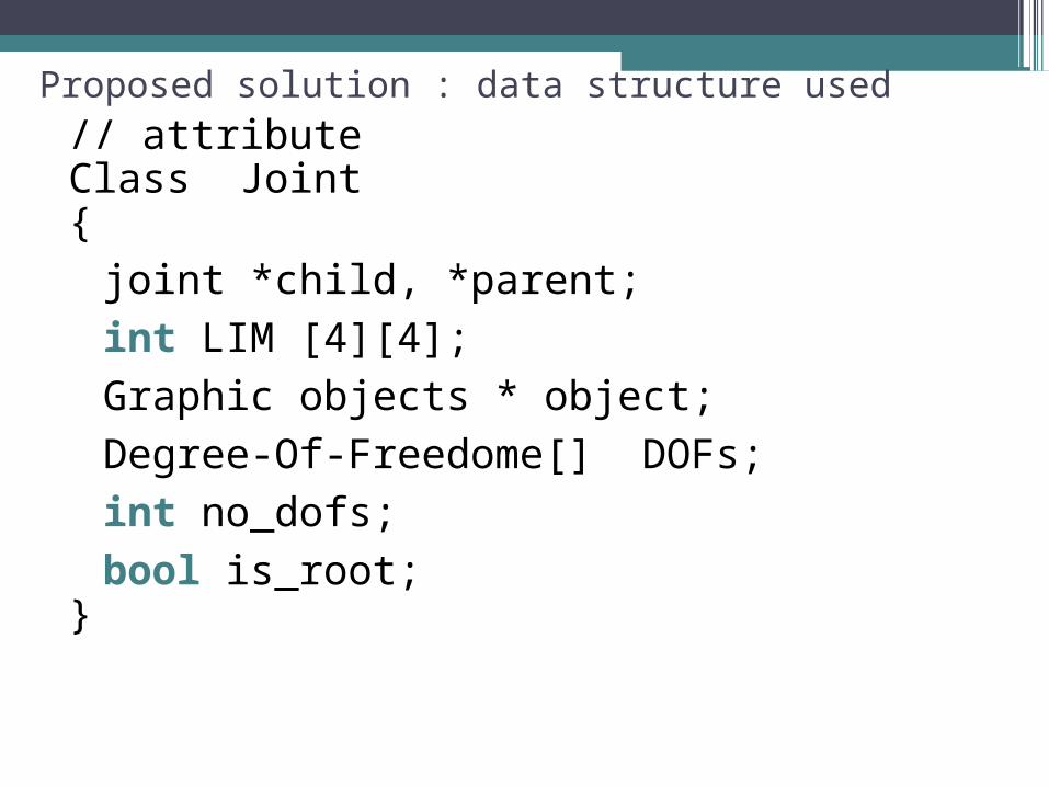
Proposed solution : data structure used// attribute Class Joint {
joint *child, *parent;
int LIM [4][4];
Graphic objects * object;
Degree-Of-Freedome[] DOFs;
int no_dofs;
bool is_root;}

Proposed solution : data structure used
// methodClass Joint {Void Move ()
{ For (int i =0 ; i< no_dofs; i++)
LIM *= DOFs[i].LIM
Compute_GIM ();
Object ->GIM = GIM * Object->LIM}
}//////////////////////////////////////////////////////////////////////////////////////
Int** Compute_GIM (joint * p){ if (p->is_root) return (P->LIM) else p->GIM = compute_GIM( P->parent)* p->LIM
}

Proposed solution : data structure usedClass Graphics Object {
Mesh m;
int LIM [4][4];
int GIM [4][4];}Class DegreeOfFreedome{ Float rest_postion ; Float max_ang_limit , min_ang_limit; Int axis; Int LIM[4][4]; ////////////////////////////////////////////////////////////////////////////////////// Void set_flex_pramaeter (float x){ rest_postion = (max_ang_limit + min_ang_limit ) * x ;} }

Approach of this paper• The sliding Axis Joint Case▫This approach use an evoluta▫Every time the angular parameter of a Dof
changes, the same parameter is used in the curve equations to determine its respective point on the curve. Then, the axis is translated to the calculated point

The Pseudo-code : for the basic model
Create the human body as a tree nodeInitialize the LIM matrix with the relationship of
a child & a parent jointDefine each joint into its parent reference frameCreate a graphic object for each joint Initialize the LIM object matrix with object
position in relation to the associated jointGenerate GIM matrix Initialize GIM by multiplying the LIM joints from
the root to the current joint with the object LIMDefine the DOF of each joint

The Pseudo-code : for the sliding Axis Joint
IF DOFAngle ! = currentAngle THENCalculate the new point of the curveTranslate the axis to the new pointEND IF

The Pseudo-code : for the relations between two joints
IF DOFAngle1 != currentAngle1 && DOFAngle2 != currentAngle2 THEN
Calculate the new DOFAngle using the DOFAngle2 and DOFAngle1
Update the currentAngle1 by the new DOFAngle
END IF

Achievements of the Proposed Solution•The achievements were
▫ the ability to represent the all types of human joints
▫sliding axis approach ▫a mechanism to represent interference of
one joint position and orientation in the motion ranges of others

Comparison between this model & other models
ModelsComparison
Simulation System SIMM
There are some limitations in the SIMM model which is the absence of some
motion axis, the absence of menisci, and the very low resolution of the mesh that
represents the bones.
Plastic Knee There is a great similarity in the patella
motion and the terminal rotation.
Internal view of the real living knee
We find a great similarity between them

The Weakness of this model• A lack in the validation process was the
impossibility of measuring the geometry of the models used in the comparison, and the angles of the performed movements
• If that was possible, they could probably reproduce specific geometry and motion for the models, yielding better comparison

Conclusion