Embed Size (px)
Citation preview

8/10/2019 Presentation 12- Contactors-Handouts.pdf
http://slidepdf.com/reader/full/presentation-12-contactors-handoutspdf 1/9
10/13/11
1
!
HVACR 4 – Electrical for Gas
Heat
Contactors
#
• A contactor is used to control an electric load
in a control system.
• Contactors make or break a set of contactsthat controls the voltage applied to some loadin HVAC systems.
• A contactor consists of a coil that opens and
closes a set of contacts due to the magneticattraction created by the coil when it is
energized.
$
Parts of a contactor
!"#$
!"&'()'*
!"&'+"$ ,"$'(-.
/.+0#&($*
1#&. ,"$'(-.
/.+0#&($*

8/10/2019 Presentation 12- Contactors-Handouts.pdf
http://slidepdf.com/reader/full/presentation-12-contactors-handoutspdf 2/9
10/13/11
2
%
Applications
• The largest electric load in any cooling systemthat requires control is the compressor.
• The contactor used in a small residential air
conditioning unit probably controls thecompressor and condenser fan motor.
• Larger Air conditioning systems will have
multiple contactors.
&
Simple schematic diagram of a contactor controlling acompressor and Condenser fan motor
'
Operation
• Different manufacturers design contactors in
different ways. But they serve the same
purpose: Opening and closing a set ofcontacts.
• The armature of a contactor is the portion that
moves.•
This can be accomplished by two ways:» A sliding armature
» A swinging armature
8/10/2019 Presentation 12- Contactors-Handouts.pdf
http://slidepdf.com/reader/full/presentation-12-contactors-handoutspdf 3/9
10/13/11
3
(
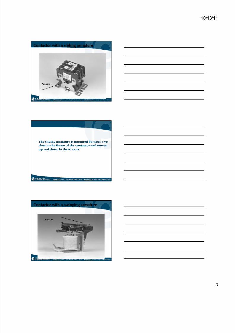
Contactor with a sliding armature
2+0('3+.
)
• The sliding armature is mounted between two
slots in the frame of the contactor and movesup and down in these slots.
*
Contactor with a swinging armature
2+0('3+.
8/10/2019 Presentation 12- Contactors-Handouts.pdf
http://slidepdf.com/reader/full/presentation-12-contactors-handoutspdf 4/9
10/13/11
4
!+
• The swinging armature is mounted on a pivot
or hinge and moves up and down in aswinging motion.
!!
• The armature of a contactor is connected by a
mechanical linkage to a set of contacts thatcauses a complete circuit when the armatureis pulled into the magnetic field produced by
the coil.
• This operation applies for both the swinging
armature and sliding armature.
!#
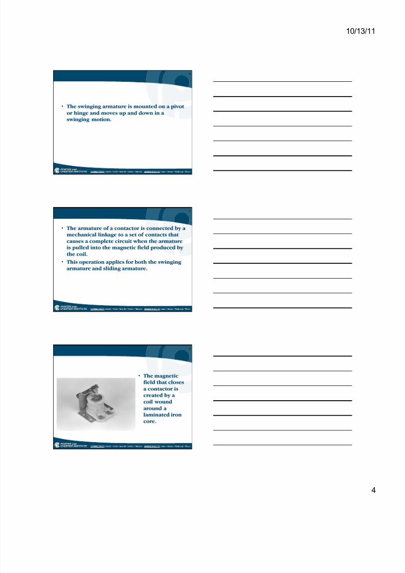
• The magneticfield that closesa contactor iscreated by a
coil woundaround alaminated ironcore.

8/10/2019 Presentation 12- Contactors-Handouts.pdf
http://slidepdf.com/reader/full/presentation-12-contactors-handoutspdf 5/9
10/13/11
5
!$
• When the coil is energized, a magnetic field iscreated around the laminated core.
• The core then becomes a electromagnet of
sufficient strength to attract the armatureclosing the contacts.
• Some contactors have a spring mounted
between the armature and the stationarycontacts to ensure the contactor opens whenthe coil is de-energized.
!%
Coils
• Coil characteristicsdepend on thetype of wire andthe manner in
which it is wound.• Coils are designed
to be operated on24, 120, 208/230and occasionally480 volts.
• To identify the coil voltage, the voltageis marked on it.
!"#$ 4"$'(-. #*
0(+5.6 7.+.8
!&
Contacts
• The contacts of a contactor make a complete
circuit when the contactor is energized,
allowing voltage to flow to the controlled load.
• Contactor are rated by the ampere draw they
can carry.
•
There are two types of loads a contactor cancontrol:
» Inductive loads ( Motors)
» Resistive loads ( Heaters)

8/10/2019 Presentation 12- Contactors-Handouts.pdf
http://slidepdf.com/reader/full/presentation-12-contactors-handoutspdf 6/9
10/13/11
6
!'
• Contacts are made of silver and cadmium, which resists sticking.
• The chemical composition of contacts can
operate at cool temperatures up to 125% oftheir current –carrying capacity.
• Contactors are usually manufactured with two
or three poles.
!(
• Two pole contactor is required for single
phase systems.
• A three pole contactor is required for three
phase systems.
!)
Troubleshooting
• To diagnose a faulty contactor requires
looking at three sections of the contactor: – The coil
– The contacts
– And the mechanical linkage
• A defect in any part of these parts can cause
the contactor to fail.

8/10/2019 Presentation 12- Contactors-Handouts.pdf
http://slidepdf.com/reader/full/presentation-12-contactors-handoutspdf 7/9
10/13/11
7
!*
The coil
• The coil must be in good condition to create astrong enough electromagnetic force to pull inthe contacts.
• It’s uncommon for the coil to become so
weak that it does not close the contacts,unless there is excessive friction to themechanical linkage.
• A coil is diagnosed as either good, open or
shorted.
#+
• The coil can be checked with an ohmmeter.
•
If the coil is shorted, resistance will read 0
• If the coil is opened, resistance will read OL
• If the coil is good, the resistance will read somemeasurable resistance.
• A coil can also be checked by applying voltage
to it and observing the contactor to see if itcloses.
#!
• A voltage reading of the coil should be taken
before checking the coil to see if the contacts
should be closed.
• If voltage is applied to it, the coil will cause a
direct short and other damage could result….
SoBE CAREFUL

8/10/2019 Presentation 12- Contactors-Handouts.pdf
http://slidepdf.com/reader/full/presentation-12-contactors-handoutspdf 8/9
10/13/11
8
##
Contacts
• The contacts must be in good condition toensure that the proper voltage reaches theload.
• A visual inspection is sufficient to diagnose
bad contacts.
• A voltage reading taken across the contacts of
the same pole will show the voltage dropacross the contacts.
#$
Contact conditions
9#:.6 (&6 ;3+&' )"&'()'*
<""6 !"&'()'*
#%
• Any voltage drop above 5% of the rated voltage is considered to be excessive.
• If you come across this, replace the contactor.
• Voltage must be applied to make this check.

8/10/2019 Presentation 12- Contactors-Handouts.pdf
http://slidepdf.com/reader/full/presentation-12-contactors-handoutspdf 9/9
10/13/11
9
#&
Mechanical linkage
• The easiest fault to diagnose.
•
Any problem with the mechanical linkage canbe detected by visual inspection.
• The mechanical linkage will usually fail do to wear, corrosion, or moisture
#'
Repairing contactors
• Contactors can be repaired by using
replacement parts.
• Some manufacturers do sell a kit that willcompletely replace the contact portion of thecontactor.
• Parts can be difficult to locate, it might be
better to just replace the contactor.
#(