Embed Size (px)
Citation preview

BOEING is a trademark of Boeing Management Company. Copyright © 2013 Boeing. All rights reserved.
Michael J. Roginski, P.E. Principal Engineer – Boeing Airport Compatibility Engineering, Pavement Lead September 1-5, 2014 Santiago, Chile
Present and Future Work Items of the ICAO Pavement Sub-Group

COPYRIGHT © 2013 THE BOEING COMPANY
Outline ICAO Pavement Sub-group Work Statement Total Re-write of Part 3-Pavements- estimated completion date
end of 2015 Unpaved Surface Requirements- Aerodrome Manual-Part 1-
Runways Revised ICAO Overload Guidance for Annex 14
New ACN/PCN Procedure- Multi-Layered Linear Elastic Method
Summary

COPYRIGHT © 2013 THE BOEING COMPANY
Updates to PCN Guidance in Part 3-Pavements Chapter 1- Procedures for Reporting Pavement Strength
PCN definition- A number expressing the bearing strength of a pavement
for ‘unrestricted operations’. What is meant by ‘unrestricted’?
• Revised section 1.1.2.1- The term unrestricted operations in the definition of PCN does not mean unlimited operations. Unrestricted refers to the relationship of PCN to the ACN, and it is permissible for an aircraft to operate without weight restriction (subject to tire pressure limitations) when the PCN is greater than or equal to the ACN. The term unlimited operations does not take into account pavement life. The PCN to be reported is such that, the pavement strength is sufficient for the current and future traffic analyzed, and should be re-evaluated if traffic changes significantly.
Current PCN guidance in ICAO Aerodrome Design Manual- Part 3 Pavements states “the airport authority can use any method of his choice to determine the load rating of his pavement.”
• New section 1.1.2.5- State may lack expertise in this area or wish to incorporate a standard methodology for performing the technical evaluation of their pavements. PSG has proposed the FAA COMFAA program as initial guidance in calculating PCN rating.
COPYRIGHT © 2013 THE BOEING COMPANY
ICAO Pavement Sub-group Activity- Updates to PCN Guidance in ADM Part 3-Pavements
Clarification was needed to determine the difference between the “using aircraft” PCN and technical PCN. Additionally, clarification of what PCN to report for a runway was added.
• Revised section 3.6.4.9e- For pavements of varying cross section and subgrade strength it may be difficult to arrive at a single PCN value to report. A decision must me made whether to report the lowest PCN or a higher PCN which would not restrict traffic. This is at the discretion of the airport authority and may depend on the frequency of operations of heavier aircraft that would be permitted by reporting a higher PCN, where the weaker pavement section is located, or if increased maintenance may be necessary.

COPYRIGHT © 2013 THE BOEING COMPANY
ICAO ACN Calculator New ACN calculator part of revision to Part 3- scaled down version of COMFAA Ability to determine ACN’s at intermediate weights. FAA to safeguard software and provide master copy to ICAO
COPYRIGHT © 2013 THE BOEING COMPANY
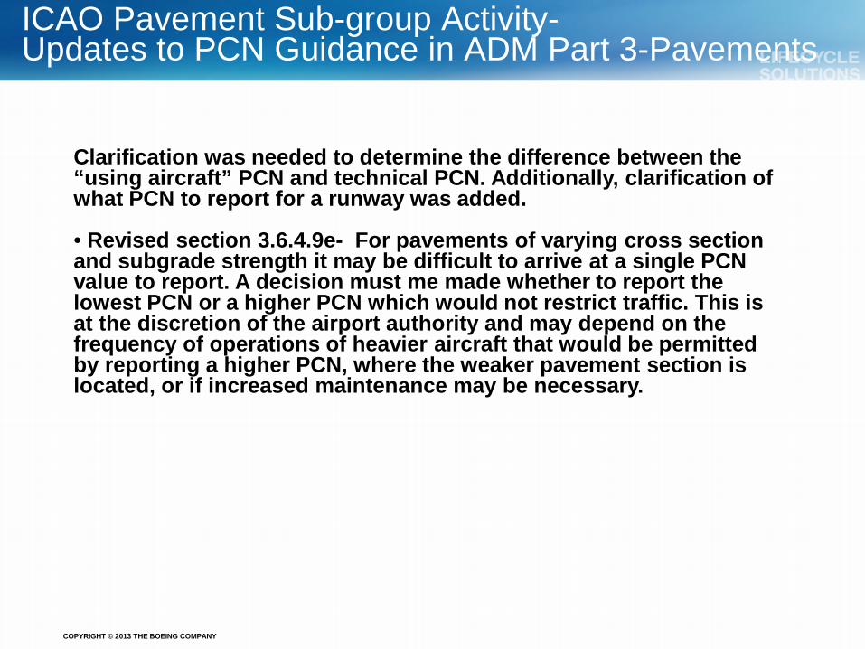
Revised Table A5-1 in Part 3- Appendix 5
• Aircraft updated from original 1983 database. Older versions such as Concorde removed and most recent models such as 787, A350 and A380 added • ACN values updated based on 2007 acceptance by ICAO of new 4 and 6 wheel alpha factors • Aircraft in table now based on minimum weight of 40 tonnes and 70 or more passengers

COPYRIGHT © 2013 THE BOEING COMPANY
Revised Table A1-1 in Part 3- Appendix 1
• Aircraft updated to match Table A5-1. Wheel arrangement nomenclature matches current industry standard based on FAA Order 5300.7
COPYRIGHT © 2013 THE BOEING COMPANY
Additional Part 3 Revisions
1. Updates to section 5.3-Surface Treatment of Runways a. Additional guidance on the pros and cons of grooving have been added b. Alternatives to grooving to achieve skid-resistance have been added. Details of the French
bituminous concrete (BBA) and stone matrix asphalt (SMA) used in China for surface wearing courses have been added in a new section 5.3.8
2. Chapter 4- State Practices
a. US practice pages in Part 3 will be replaced with references and web links to FAA advisory
circulars (i.e. 150/5320-6E) and design software (i.e. Faarfield 1.4) currently being used for the design, evaluation and strength reporting of pavements. Nomographs will all be removed.
b. United Kingdom and Canada state practice sections will be removed completely.
3. Miscellaneous
a. Remove Appendix 2-Fortran Code, Appendix 3-French design graphs and Appendix 4-US background information.
b. Minor re-wording of Chapters 6- Protection of Asphalt Pavements and Chapter 7-Structural Concerns for Culverts and Bridges
COPYRIGHT © 2013 THE BOEING COMPANY
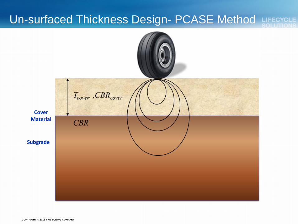
Un-surfaced Thickness Design- PCASE Method
Subgrade
Cover Material

COPYRIGHT © 2013 THE BOEING COMPANY
ICAO ADM Part 1- Runways 5.3.22 Since the graded portion of a strip is provided to minimize the hazard to an aircraft running off the runway, it should be graded in such a manner as to prevent the collapse of the nose landing gear of the aircraft. The surface should be prepared in such a manner as to provide drag to an aircraft and below the surface, it should have sufficient bearing strength to avoid damage to the aircraft. To meet these divergent needs, the following guidelines are provided for preparing the strip. Aircraft manufacturers consider that a depth of 15 cm is the maximum depth to which the nose gear may sink without collapsing. Therefore, it is recommended that the soil at a depth of 15 cm below the finished strip surface be prepared to have a bearing strength of California Bearing Ratio (CBR) value of 15 to 20. The intention of this underlying prepared surface is to prevent the nose gear from sinking more than 15 cm. The top 15 cm may be of lesser strength which would facilitate deceleration of aircraft.
Strength- Runway End Safety Areas 5.4.13 A runway end safety area should be so prepared or constructed as to reduce the risk of damage to an aeroplane undershooting or overrunning the runway, enhance aeroplane deceleration, and facilitate the movement of rescue and fire fighting vehicles. See 5.3.22 for guidance on the minimum strength of the runway end safety area. The new ICAO guidance will make reference to Part 3- Pavements for strength requirements. The current 15 cm of surface soft material for aircraft deceleration on overruns should not affect continued landing on an undershoot condition.
Strength- Runway Strip
Strength- Runway Shoulders 5.2.10 A runway shoulder should be prepared or constructed so as to be capable, in the event of an aeroplane running off the runway, of supporting the aeroplane without inducing structural damage to the aeroplane and of supporting ground vehicles which may operate on the shoulder. The new ICAO guidance will make reference to Part 3- Pavements for strength requirements.

COPYRIGHT © 2013 THE BOEING COMPANY
Required CBR of Cover Material for and Mat Pavements
Previous US Corps Method Made Use of Nomographs
Typical un-surfaced shoulders and RESA will be at low CBR- natural soil conditions. Stronger cover material needs to be added to support subgrade.

COPYRIGHT © 2013 THE BOEING COMPANY
PCASE SOLUTION – THICKNESS REQUIREMENT
Page 12
Methodology: PCASE Use PCASE modified CBR equation:
Note: Formula verified with Dr. Gonzalez of ERDC, and currently used in PCASE analysis for un-surfaced airfields, reference document GL-89-5, “Design Criteria for Aggregate-Surfaced Roads and Airfields, Yu T. Chou C: number of coverages P: ESWL. Function of gear type and thickness A: tire contact area.
/*1.8/)087.log*1275(.cov ACBRPCt er −+= π
Method assumes a single layer of cover material of higher CBR can be used to support natural soil. Soil strength determined from DCP testing.
COPYRIGHT © 2013 THE BOEING COMPANY
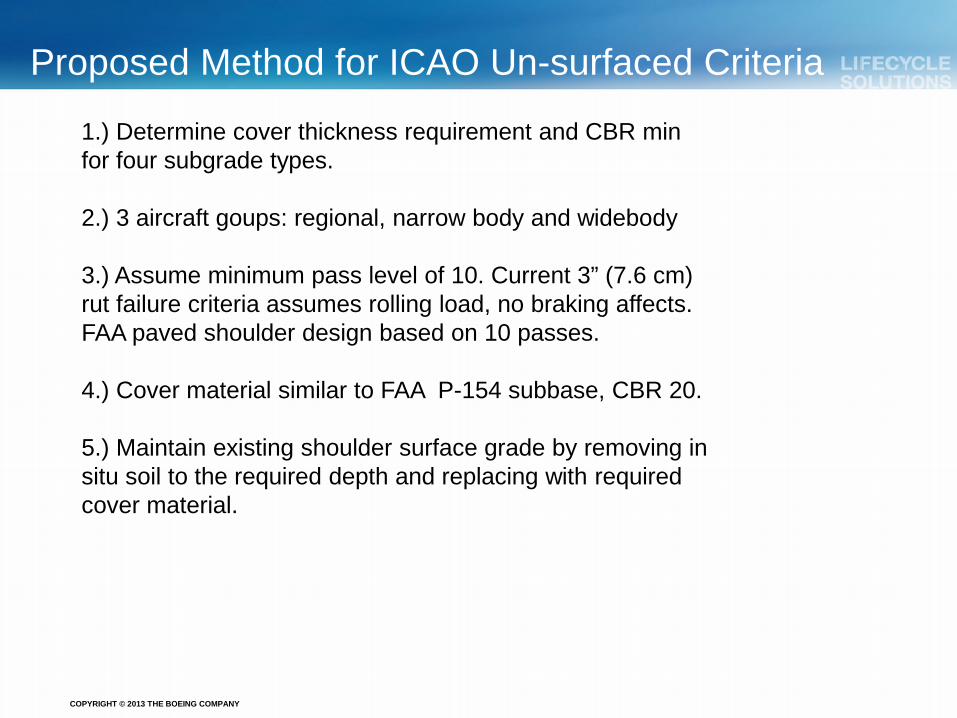
Proposed Method for ICAO Un-surfaced Criteria
1.) Determine cover thickness requirement and CBR min for four subgrade types. 2.) 3 aircraft goups: regional, narrow body and widebody 3.) Assume minimum pass level of 10. Current 3” (7.6 cm) rut failure criteria assumes rolling load, no braking affects. FAA paved shoulder design based on 10 passes. 4.) Cover material similar to FAA P-154 subbase, CBR 20. 5.) Maintain existing shoulder surface grade by removing in situ soil to the required depth and replacing with required cover material.

COPYRIGHT © 2013 THE BOEING COMPANY
Thickness requirements for Cover Material

COPYRIGHT © 2013 THE BOEING COMPANY
Proposal for ICAO Guidance
Group 1- Regional aircraft less than 30K (13.6 K kg) wheel loads Group 2- Narrow body aircraft 30K-45K wheel loads Group 3- Widebody aircraft > 50K (22.7 K kg) wheel loads Conservative assumption of P-154 type cover material, CBR 20 min for all cases

COPYRIGHT © 2013 THE BOEING COMPANY
Overload Criteria- ADM Part 3- Chapter 2
FAA and ICAO Overload Criteria
Occasional minor aircraft overloading is acceptable with only limited loss of pavement life expectancy and relatively small acceleration of pavement deterioration.
Those operations in which Magnitude and /or Frequency does not require a detailed technical analysis the following criteria is suggested. • Flexible pavement ACN should not exceed 10% of the reported PCN
• Rigid pavement ACN should not exceed 5% of the reported PCN
Annual overload movements should not exceed ~5% of total annual
aircraft movements
Overloads should not be allowed: - If pavement is exhibiting signs of distress - During periods of thaw - When pavement/subgrade is weakened by water

COPYRIGHT © 2013 THE BOEING COMPANY
Full-scale tests will consider: Percent overload based on PCN.
Various overload levels up to 40-50% to be considered. Current ICAO overload guidance for flexible pavements only 10%.
Percent overload based on CDF-.10, .50, 1.0
Used pavement life expressed as cumulative damage factor (CDF). Effect of overload on pavement life to be compared against ACN/PCN ratio
Full-scale tests will consider: Dual, Dual tandem and 6 wheel gears Monitoring rutting will give
indication of subbase failure due to overload
Overload Criteria for Flexible Pavements-Testing Planned for 2014
COPYRIGHT © 2013 THE BOEING COMPANY
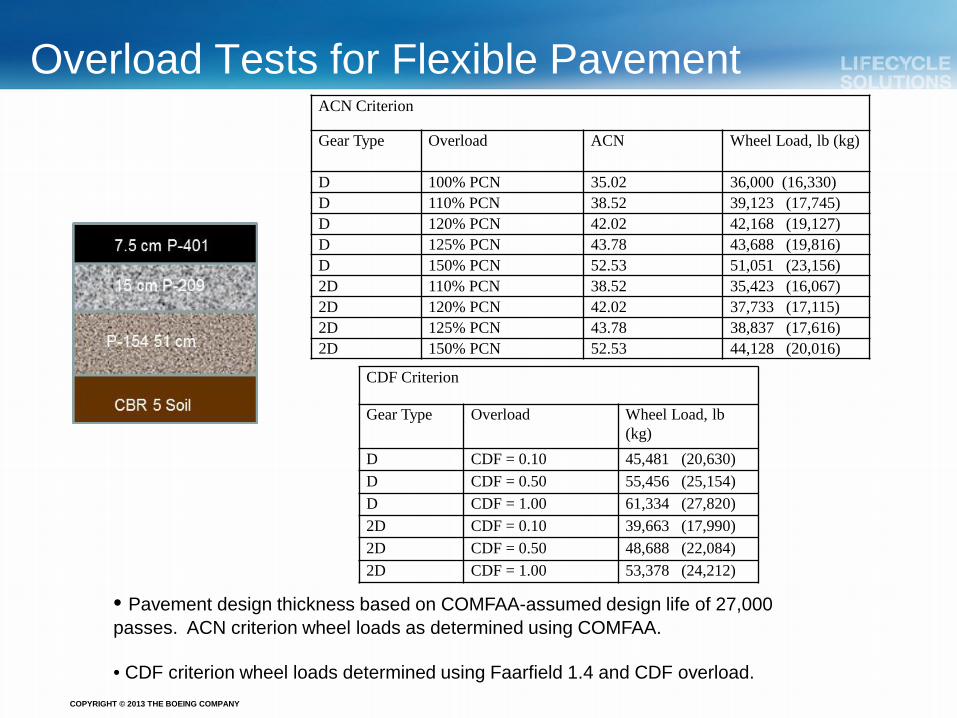
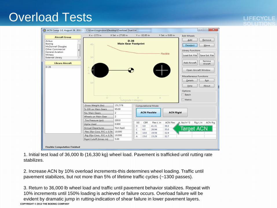
Overload Tests for Flexible Pavement ACN Criterion
Gear Type Overload ACN Wheel Load, lb (kg)
D 100% PCN 35.02 36,000 (16,330) D 110% PCN 38.52 39,123 (17,745) D 120% PCN 42.02 42,168 (19,127) D 125% PCN 43.78 43,688 (19,816) D 150% PCN 52.53 51,051 (23,156) 2D 110% PCN 38.52 35,423 (16,067) 2D 120% PCN 42.02 37,733 (17,115) 2D 125% PCN 43.78 38,837 (17,616) 2D 150% PCN 52.53 44,128 (20,016)
CDF Criterion
Gear Type Overload Wheel Load, lb (kg)
D CDF = 0.10 45,481 (20,630) D CDF = 0.50 55,456 (25,154) D CDF = 1.00 61,334 (27,820) 2D CDF = 0.10 39,663 (17,990) 2D CDF = 0.50 48,688 (22,084) 2D CDF = 1.00 53,378 (24,212)
• Pavement design thickness based on COMFAA-assumed design life of 27,000 passes. ACN criterion wheel loads as determined using COMFAA. • CDF criterion wheel loads determined using Faarfield 1.4 and CDF overload.
COPYRIGHT © 2013 THE BOEING COMPANY
Overload Tests
1. Initial test load of 36,000 lb (16,330 kg) wheel load. Pavement is trafficked until rutting rate stabilizes. 2. Increase ACN by 10% overload increments-this determines wheel loading. Traffic until pavement stabilizes, but not more than 5% of lifetime traffic cycles (~1300 passes). 3. Return to 36,000 lb wheel load and traffic until pavement behavior stabilizes. Repeat with 10% increments until 150% loading is achieved or failure occurs. Overload failure will be evident by dramatic jump in rutting-indication of shear failure in lower pavement layers.
COPYRIGHT © 2013 THE BOEING COMPANY
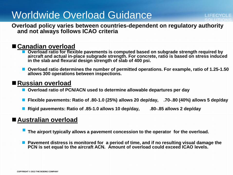
Worldwide Overload Guidance Overload policy varies between countries-dependent on regulatory authority
and not always follows ICAO criteria Canadian overload
Overload ratio for flexible pavements is computed based on subgrade strength required by aircraft and actual in-place subgrade strength. For concrete, ratio is based on stress induced in the slab and flexural design strength of slab of 400 psi.
Overload ratio determines the number of permitted operations. For example, ratio of 1.25-1.50 allows 300 operations between inspections.
Russian overload Overload ratio of PCN/ACN used to determine allowable departures per day
Flexible pavements: Ratio of .80-1.0 (25%) allows 20 dep/day, .70-.80 (40%) allows 5 dep/day
Rigid pavements: Ratio of .85-1.0 allows 10 dep/day, .80-.85 allows 2 dep/day
Australian overload
The airport typically allows a pavement concession to the operator for the overload.
Pavement distress is monitored for a period of time, and if no resulting visual damage the
PCN is set equal to the aircraft ACN. Amount of overload could exceed ICAO levels.

COPYRIGHT © 2013 THE BOEING COMPANY
Aircraft Classification Number – NEW Method
ICAO-PSG-Item.7 “The PSG agreed that the introduction of an ACN determination procedure
more consistent with modern pavement design methods needs to be addressed quickly knowing that the development of such a procedure would take time. Thoughts toward this new approach will be carried on during the 2012-2015 work cycle. Incorporation of new methodology expected in 2018 timeframe.”
OBJECTIVES: To align the new ACN procedure with the current practice for pavement design
and analysis, multi-layered linear elastic systems such as Faarfield. Attempt to keep the current ACN-PCN structure unchanged (number, pavement
type, subgrade code…). Develop a new and unique procedure for PCN determination using the same
linear elastic methods. BENEFITS: Eliminate inconsistency between new pavement design and pavement ratings
which are based on different analysis methods. Alpha factors and thickness equivalency factors would no longer be needed.

COPYRIGHT © 2013 THE BOEING COMPANY
Details of the New Method Retaining the same appearance and simplicity of the current system is important, less impact on the airport authority and their willingness to accept a new methodology. The new procedure would require the following steps and parameters:
i. Define typical flexible reference structures (Surface and base asphalt layer thicknesses and moduli have to be fixed),
ii. Define the new DSWL standard condition (1.5MPa suggested),
iii. Define standard number of coverages of an aircraft landing gear (36,500 for initial evaluation-i.e. 10 coverages per day over 10 yrs)
iv. Compute the DSWL (in kg) at standard conditions which gives the same pavement thickness as the aircraft used for the ACN computation.
v. Pavement thickness is computed by adjusting (subbase) thickness only, such that CDF is equal to 1.0
COPYRIGHT © 2013 THE BOEING COMPANY
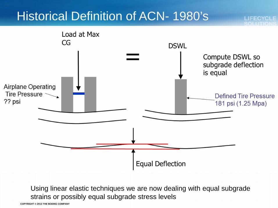
Historical Definition of ACN- 1980’s
Using linear elastic techniques we are now dealing with equal subgrade strains or possibly equal subgrade stress levels

COPYRIGHT © 2013 THE BOEING COMPANY
Reference Structures for the ACN Calculation Pavement structure Surface layer and base layer are fixed, only the subbase layer is
adjusted to reach a CDF of 1 (for a fixed number of passes) Pavement subbase thickness is determined for each aircraft. DSWL is
then computed at the same thickness with ACN = 2* DSWL:
The subgrade is defined by its Young modulus E through the equivalency
E = 10 x CBR ~1500 x CBR (E in PSI) The design criterion is the subgrade failure

COPYRIGHT © 2013 THE BOEING COMPANY
Preliminary ACN Results – CBR 10 (E=100 MPa)

COPYRIGHT © 2013 THE BOEING COMPANY
Preliminary ACN Results – CBR 3 (E=30 MPa)

COPYRIGHT © 2013 THE BOEING COMPANY
Summary and Future Work • For D type aircraft the results derived from Alizé-LCPC and FAARFIELD correlate
quite well across all subgrade strengths
• For 2D and 3D aircraft, the difference between Alizé-LCPC and FAARFIELD become quite significant
• For high subgrade strengths, FAARFIELD is close to current aircraft ACN’s (typically lower) while Alizé-LCPC leads to higher ACNs;
• For low subgrade strengths both are significantly higher than current ACNs
Future Work • Incorporate the Alize method of looking at multi-axle loading. Faarfield uses a
pass/coverage approach whereas Alize uses a multi-peak integration approach. This will effect the CDF computation significantly and the ACN computation slightly.
• Rigid pavements need to be addressed- currently assumed not to be as discrepant
as the flexible pavement failure models • Consider different reference structures and coverage levels for ACN determination

COPYRIGHT © 2013 THE BOEING COMPANY
Preguntas?
Muchas Gracias!