Embed Size (px)
Citation preview

BESSERMATICMODEL MS-12 (18 1/2)
W/LSC-100 SIDE SHIFTER
World Headquarters801 Johnson St. • Alpena, Michigan, 49707 • U.S.A.
Phone (517) 354-4111
INSTALLATION MANUAL
466372F0001US
APRIL 2000 • US$250

COMPANY NAME: ................................................................
SERIAL NUMBER: ................................................................
ASSEMBLY NUMBER: ................................................................
WIRING DIAGRAM NUMBER: ................................................................
INSTALLATION DRAWING NUMBER: ..............................................................

466372F0001US D1 10AP00 i
Besser-matic MS-12 W/Side Shifter 18.5”INSTALLATION MANUAL
MS-12 W/SIDE SHIFTER
TABLE OF CONTENTS
LIST OF ILLUSTRATIONS . . . . . . . . . . . . . . . . . . . . . . . . . . . . . . . . . . . . . . . . . . . . . . . . . . . . . . . . . . .ii
SAFETY BULLETIN . . . . . . . . . . . . . . . . . . . . . . . . . . . . . . . . . . . . . . . . . . . . . . . . . . . . . . . . . . . . . . . .iv
SAFETY SIGNS v
ELECTRICAL DATA . . . . . . . . . . . . . . . . . . . . . . . . . . . . . . . . . . . . . . . . . . . . . . . . . . . . . . . . . . . . . . . .ix
SECTION 1 SPECIFICATIONS . . . . . . . . . . . . . . . . . . . . . . . . . . . . . . . . . . . . . . . . . . . . . . . . . . . . .x
SECTION 2 PREPARE SITE 2.1 ITEMS REQUIRED TO INSTALL AN MS-12 W/SIDE SHIFTER . . . . . . . . . . . . . . . . . .2-12.2 PREPARE THE LOCATION OF THE MS-12 W/SIDE SHIFTER . . . . . . . . . . . . . . . . . .2-22.3 PREPARE ELECTRICAL SUPPLY TO THE MS-12 W/SIDE SHIFTER . . . . . . . . . . . . .2-62.4 PREPARE HYDRAULIC SUPPLY TO THE MS-12 W/SIDE SHIFTER . . . . . . . . . . . . .2-82.5 PLACE CONCRETE FLOOR . . . . . . . . . . . . . . . . . . . . . . . . . . . . . . . . . . . . . . . . . . .2-8
SECTION 3 INSTALLATION3.1 INSTALL SIDE SHIFTER AND CRAWLER RAILS . . . . . . . . . . . . . . . . . . . . . . . . . . . .3-13.2 INSTALL ACCUMULATORS3-73.3 INSTALL BESSER-MATIC FRAME ASSEMBLY . . . . . . . . . . . . . . . . . . . . . . . . . . . . .3-83.4 INSTALL STABILIZERS AND LOWER SPADES . . . . . . . . . . . . . . . . . . . . . . . . . . . .3-123.5 INSTALL RACKVEYOR . . . . . . . . . . . . . . . . . . . . . . . . . . . . . . . . . . . . . . . . . . . . . .3-153.6 INSTALL SIDE SHIFTER . . . . . . . . . . . . . . . . . . . . . . . . . . . . . . . . . . . . . . . . . . . . .3-163.7 INSTALL POWER UNIT AND VALVE STAND . . . . . . . . . . . . . . . . . . . . . . . . . . . . . .3-173.8 FILL HYDRAULIC POWER UNIT . . . . . . . . . . . . . . . . . . . . . . . . . . . . . . . . . . . . . . .3-183.9 INSTALL THE CONVEYORS . . . . . . . . . . . . . . . . . . . . . . . . . . . . . . . . . . . . . . . . . .3-193.10 MAKE ELECTRICAL INSTALLATION . . . . . . . . . . . . . . . . . . . . . . . . . . . . . . . . . . . .3-243.11 INSTALL SAFETY GATES . . . . . . . . . . . . . . . . . . . . . . . . . . . . . . . . . . . . . . . . . . . .3-263.12 SECURE FRAME ASSEMBLY . . . . . . . . . . . . . . . . . . . . . . . . . . . . . . . . . . . . . . . . .3-273.13 CHECK LIST . . . . . . . . . . . . . . . . . . . . . . . . . . . . . . . . . . . . . . . . . . . . . . . . . . . . . .3-28
Table of Contents

466372F0001US D1 10AP00ii
LIST OF ILLUSTRATIONSSECTION 1 SPECIFICATIONS
1.0 MS-12 w/Side Shifter Dimensions . . . . . . . . . . . . . . . . . . . . . . . . . . . . . . . . . . . . . . . .1-31.1 Operator Orientation . . . . . . . . . . . . . . . . . . . . . . . . . . . . . . . . . . . . . . . . . . . . . . . . . .1-4
SECTION 2 SITE PREPARATION2.1 Location of Equipment by Center Lines . . . . . . . . . . . . . . . . . . . . . . . . . . . . . . . . . . . .2-32.2 MS-12 Besser-matic w/Side Shifter . . . . . . . . . . . . . . . . . . . . . . . . . . . . . . . . . . . . . . .2-42.3 Accumulator Frame Assemblies . . . . . . . . . . . . . . . . . . . . . . . . . . . . . . . . . . . . . . . . .2-52.4 MS-12 Besser-Matic Standard Electrical Panel Location and Loader Stub-ups . . . . . .2.72.5 MS-12 Besser-Matic Electrical Panel Connections . . . . . . . . . . . . . . . . . . . . . . . . . . .2-72.6 MS-12 Besser-Matic Hydraulic Installation . . . . . . . . . . . . . . . . . . . . . . . . . . . . . . . . .2-92.7 Standard Location for Hydraulic Valve Stand and 8 G.P.M. Power Unit . . . . . . . . . . . .2-102.8 Remote Location for Hydraulic Valve Stand and 8 G.P.M. Power Unit . . . . . . . . . . . .2-10
SECTION 3 INSTALLATION3.1 Rail Anchor with Shims . . . . . . . . . . . . . . . . . . . . . . . . . . . . . . . . . . . . . . . . . . . . . . . .3-13.2 Anchor Bolt . . . . . . . . . . . . . . . . . . . . . . . . . . . . . . . . . . . . . . . . . . . . . . . . . . . . . . . .3-23.3 Stop Block . . . . . . . . . . . . . . . . . . . . . . . . . . . . . . . . . . . . . . . . . . . . . . . . . . . . . . . . .3-23.4 Notches on Crawler Rails . . . . . . . . . . . . . . . . . . . . . . . . . . . . . . . . . . . . . . . . . . . . . .3-33.5 Side Shifter and Crawler Anchor Plates and Shims Installation . . . . . . . . . . . . . . . . . .3-43.6 Side Shifter and Crawler Rail Installation . . . . . . . . . . . . . . . . . . . . . . . . . . . . . . . . . .3-53.7 Side Shifter and Crawler Rail Installation (2) . . . . . . . . . . . . . . . . . . . . . . . . . . . . . . . .3-63.8 Side Shifter and Crawler Rail Installation (3) . . . . . . . . . . . . . . . . . . . . . . . . . . . . . . . .3-63.9 Lift Accumulators Using Crane . . . . . . . . . . . . . . . . . . . . . . . . . . . . . . . . . . . . . . . . . .3-73.10 Install Frame (1) . . . . . . . . . . . . . . . . . . . . . . . . . . . . . . . . . . . . . . . . . . . . . . . . . . . . .3-83.11 Install Frame (2) . . . . . . . . . . . . . . . . . . . . . . . . . . . . . . . . . . . . . . . . . . . . . . . . . . . . .3-83.12 Frame Assembly . . . . . . . . . . . . . . . . . . . . . . . . . . . . . . . . . . . . . . . . . . . . . . . . . . . . .3-93.13 Anchor Cross Channel Tracks . . . . . . . . . . . . . . . . . . . . . . . . . . . . . . . . . . . . . . . . . .3-103.14 Anchor Braces, Angle Support with Raceway and Roller Guides . . . . . . . . . . . . . . . .3-113.15 Installing Stabilizers on Frame Tracks . . . . . . . . . . . . . . . . . . . . . . . . . . . . . . . . . . . .3-123.16 Assembling Lower Spades to Stabilizers . . . . . . . . . . . . . . . . . . . . . . . . . . . . . . . . . .3-133.17 Bolting Spades . . . . . . . . . . . . . . . . . . . . . . . . . . . . . . . . . . . . . . . . . . . . . . . . . . . . .3-133.18 Centering Spade Assembly 3-143.19 Stabilizer Wheel Screws . . . . . . . . . . . . . . . . . . . . . . . . . . . . . . . . . . . . . . . . . . . .3-143.20 Position of Rackveyor . . . . . . . . . . . . . . . . . . . . . . . . . . . . . . . . . . . . . . . . . . . . . . . .3-153.21 Position of Side Shifter and Rackveyor . . . . . . . . . . . . . . . . . . . . . . . . . . . . . . . . . . .3-163.22 The Vavle Stand . . . . . . . . . . . . . . . . . . . . . . . . . . . . . . . . . . . . . . . . . . . . . . . . . . . .3-173.23 The Hydraulic Power Unit . . . . . . . . . . . . . . . . . . . . . . . . . . . . . . . . . . . . . . . . . . . . .3-183-24 Pump Rotation . . . . . . . . . . . . . . . . . . . . . . . . . . . . . . . . . . . . . . . . . . . . . . . . . . . . .3-183-25 Splice Plate . . . . . . . . . . . . . . . . . . . . . . . . . . . . . . . . . . . . . . . . . . . . . . . . . . . . . . .3-193-26 Conveyor Bolted to Accumulators . . . . . . . . . . . . . . . . . . . . . . . . . . . . . . . . . . . . . . .3-193-27 Adjustable Legs . . . . . . . . . . . . . . . . . . . . . . . . . . . . . . . . . . . . . . . . . . . . . . . . . . . .3-193-28 Unloading Conveyor Bolted to Pallet Transfer Stand . . . . . . . . . . . . . . . . . . . . . . . . .3-203.29 Conveyor Bolted to Pallet Transfer . . . . . . . . . . . . . . . . . . . . . . . . . . . . . . . . . . . . . . .3-20
Besser-matic MS-12 W/Side Shifter 18.5”INSTALLATION MANUALList of Illustrations

LIST OF ILLUSTRATIONS
3.30 Conveyor on Ms-12 w/Side Shifter . . . . . . . . . . . . . . . . . . . . . . . . . . . . . . . . . . . . . .3-213.31 Overall Installation Drawing (Top View) . . . . . . . . . . . . . . . . . . . . . . . . . . . . . . . . . . .3-223.32 Overall Installation Drawing (Elevation View) . . . . . . . . . . . . . . . . . . . . . . . . . . . . . . .3-233.33 Graphic Control Station . . . . . . . . . . . . . . . . . . . . . . . . . . . . . . . . . . . . . . . . . . . . . .3-243.34 Quick Disconnect . . . . . . . . . . . . . . . . . . . . . . . . . . . . . . . . . . . . . . . . . . . . . . . . . . .3-243.35 Stabilizer Cat Tracks . . . . . . . . . . . . . . . . . . . . . . . . . . . . . . . . . . . . . . . . . . . . . . . . .3-243.36 Frame and Accumulator Raceways . . . . . . . . . . . . . . . . . . . . . . . . . . . . . . . . . . . . . .3-253.37 Safety Gate (R.H Side Shown) . . . . . . . . . . . . . . . . . . . . . . . . . . . . . . . . . . . . . . . . .3-263.38 Secure Frame Assembly . . . . . . . . . . . . . . . . . . . . . . . . . . . . . . . . . . . . . . . . . . . . . .3-27
Besser-matic MS-12 W/Side Shifter 18.5”INSTALLATION MANUAL
iii466372F0001US D1 10AP00
Table of ContentsMS-10 Installation

Besser-matic MS-12 W/Side Shifter 18.5”INSTALLATION MANUAL
iv 466372F0001US D1 10AP00
Safety Bulletin
SAFETY BULLETINThis notice is issued to advise you that some previously accepted shop practices may not be keeping up withchanging Federal and State Safety and Health Standards. Your current shop practices may not emphasize theneed for proper precautions to insure safe operation and use of machines, tools, automatic loaders and alliedequipment and/or warn against the use of certain solvents or other cleaning substances that are now consid-ered unsafe or prohibited by law. Since many of your shop practices may not reflect current safety practicesand procedures, particularly with regard to the safe operation of equipment, it is important that you reviewyour practices to ensure compliance with Federal and State Safety and Health Standards.
IMPORTANTThe operation of any machine or power-operated device can be extremely hazardous unless propersafety precautions are strictly observed. Observe the following safety precautions:
Always be sure proper guarding is in place for all pinch, catch, shear, crush and nip points.
Always make sure that all personnel are clear of the equipment before starting it.
Always be sure the equipment is properly grounded.
Always turn the main electrical panel off and lock it out in accordance with published lockout/tag-outprocedures prior to making adjustments, repairs, and maintenance.
Always wear appropriate protective equipment like safety glasses, safety shoes, hearing protection and hard hats.
Always keep chemical and flammable material away from electrical or operating equipment.
Always maintain a safe work area that is free from slipping and tripping hazards.
Always be sure appropriate safety devices are used when providing maintenance and repairs to allequipment.
Never exceed the rated capacity of a machine or tool.
Never modify machinery in any way without prior written approval of the Besser EngineeringDepartment.
Never operate equipment unless proper maintenance has been regularly performed.
Never operate any equipment if unusual or excessive noise or vibration occurs.
Never operate any equipment while any part of the body is in the proximity of potentially hazardousareas.
Never use any toxic flammable substance as a solvent cleaner.
Never allow the operation or repair of equipment by untrained personnel.
Never climb or stand on equipment when it is operational.
It is important that you review Federal and State Safety and Health Standards on a continual basis. All shopsupervisors, maintenance personnel, machine operators, tool operators, and any other person involved in thesetup, operation, maintenance, repair or adjustment of Besser-built equipment should read and understandthis bulletin and Federal and State Safety and Health Standards on which this bulletin is based.
SAFETY SIGNS

Besser-matic MS-12 W/Side Shifter 18.5”INSTALLATION MANUAL
v466372F0001US D1 10AP00
Safety Signs
SAFETY SIGNSSign Description Required1 Electric Motor ..........................................................................................................12 All Machines............................................................................................................1
All Panels ................................................................................................................13 Mixer........................................................................................................................44 Block Machine.........................................................................................................1
SF-7 Cuber..............................................................................................................8BTO-6......................................................................................................................2Overhead Block Transfer .........................................................................................3Depalleter ................................................................................................................2AF-7 Block Pusher ..................................................................................................2
5 Concrete Products Machine....................................................................................16 Concrete Products Machine....................................................................................17 Concrete Products Machine....................................................................................28 Besser-Matic ...........................................................................................................49 Besser-Matic ...........................................................................................................410 Pallet Transport System ..........................................................................................411 LSC-40A..................................................................................................................4
Overhead Block Transfer .........................................................................................412 Conveyors ...............................................................................................................613 SF-7 Cuber..............................................................................................................814 AF-7 Block Pusher ..................................................................................................2
Pallet Transport System ..........................................................................................415 All Machines............................................................................................................1
All Panels ................................................................................................................116 SF-7 Cuber..............................................................................................................3
AF-7 Block Pusher ..................................................................................................2Slat Conveyors ........................................................................................................2
To order safety decals, contact your local Besser representativeor the Besser Central Order Department.
Thank you!

Besser-matic MS-12 W/Side Shifter 18.5”INSTALLATION MANUAL
vi 466372F0001US D1 10AP00
Safety Signs
DANGER
PELIGRO
Mixer blade hazard.Close front paneland stay clearduring operation.Follow lockout procedure before servicing.
113237F0410Mixer Blade Hazard
Width 4 1/2 inchHeight 1/4 inch
DANGER
PELIGROPELIGRO
High voltage.Follow lockoutprocedure beforeservicing panel or machine.
Large 113236F0409High Voltage
Width 4 1/2 inchHeight 9 5/8 inch
Small 113236F0204High VoltageWidth 2 inch
Height 4 1/8 inch
DANGER
PELIGRO
Crush hazards.Stay clear ofmachine.Follow lockoutprocedurebefore servicing.
113240F0307Crush Hazard
Width 3 1/2 inchHeight 7 1/2 inch
DANGER
PELIGRO
Crush hazard.Stay clear.Follow lockoutprocedure beforeservicing.
114688F0906Crush Hazard
Width 6 1/4 inchHeight 9 1/2 inch
DANGER
PELIGRO
Nip points.Stay clear. Followlockout procedurebefore servicing.
114692F1006Nip Points
Width 5 3/4 inchHeight 9 1/2 inch
WARNING
MUCHOCUIDADO
Fall hazard.Stay clear.
114689F0804Fall Hazard
Width 4 1/2 inchHeight 7 3/4 inch
1 2 3
4 5 6

Besser-matic MS-12 W/Side Shifter 18.5”INSTALLATION MANUAL
466372F0001US D1 10AP00
Safety Signs
vii
DANGER
PELIGRO
Shear hazard.Fall hazard.Stay clear. Followlockout procedurebefore servicing.
114691F1006Shear and Fall Hazards
Width 5 3/4 inchHeight 9 3/4 inch
WARNING
MUCHOCUIDADO
Falling objects.Hard hat area.
114690F0805Falling Objects
Width 4 3/4 inchHeight 8 inch
DANGER
PELIGRO
Crush hazard.Stay clear oftransfer area.Follow lockout procedure beforeservicing.
113242F0409Crush Hazard
Width 4 1/2 inchHeight 9 5/8 inch
DANGER
PELIGRO
Crush hazard.Stay clear of carand crawler.Follow lockoutprocedure beforeservicing.
Vertical: 113245F0704 Horizontal:113245F1005Crush Hazard
Vertical: Width 4 1/8 inchVertical: Height 7 inch
Horizontal: Width 10 inchHorizontal: Height 5 3/4 inch
SAFETYINSTRUCTIONS
INSTRUCCIONESDE SEGURIDAD
SUGGESTEDLOCKOUTPROCEDURE1. Announce lockout to other employees.2. Turn power off at main panel.3. Lockout power in off position.4. Put key in pocket.
5. Clear machine of all personnel.
6. Test lockout by hitting run button.
7. Block, chain or release stored energy sources.
8. Clear machine of personnel before restarting machine.
113249F0410Safety instructions decal-
Suggested Lock-out procedureWidth 4 inch
Height 10 inch
DANGER
PELIGRO
Falling objects.Stay clear oftransfer area.Follow lockoutprocedure beforeservicing.
113243F0410Falling Objects
Width 4 1/2 inchHeight 10 inch
7 9
11
8
10 12

Besser-matic MS-12 W/Side Shifter 18.5”INSTALLATION MANUAL
viii 466372F0001US D1 10AP00
Safety Signs
DANGER
PELIGROCrush hazard.Stay clear of machine. Follow lockout procedure before servicing.
DANGER
PELIGROCrush hazards.Stay clear of machine. Follow lockout procedure before servicing.
113238F1005Crush HazardWidth 10 inch
Height 5 3/4 inch
113239F0604Crush Hazard
Width 6 5/8 inchHeight 4 inch
DANGER
PELIGROCrush and pinchpoints. Stay clearof machine. Followlockout procedurebefore servicing.
WARNING MUCHOCUIDADO
Nip hazard.
lockout procedureconveyor. Follow
before servicing.
stay clear of
113241F0605Crush and Pinch Points
Width 6 5/8 inchHeight 4 inch
113246F0704Nip HazardWidth 7 inch
Height 4 1/2 inch
DANGER
PELIGROCrush hazard.
secure elevatorprocedure and
before servicing.
Follow lockout
DANGER
PELIGROCrush and pinch-
before servicing.lockout procedureconveyor. Followpoints. Stay off
113247F1006Crush HazardWidth 10 inchHeight 6 inch
113250F1006Crush and Pinch Points Hazard
Width 10 inchHeight 6 inch
13
15
14
17
16
18

For safety purposes, Besser Company requires that this equipment be connected to a lockable electrical disconnect.
Besser-matic MS-12 W/Side Shifter 18.5”INSTALLATION MANUAL
ix466372F0001US D1 10AP00
ELECTRICAL DATA
Plant Power Supply 460 volt, 3 phase, 60 hz
Total Horsepower 74
Total Kilowatts 55.18
Control Panel Transformer 2000 volt-amps
Total Amp Load 118.53
Recommended Branch Circuit Distribution Switch 200 amp
Recommended Branch Circuit Fuse (FRS-R) 150 amp
Recommended Branch Feeder (THHN) 1/0 AWG (53.5mm2)
Recommended Branch Circuit Feeder Conduit 1.25 inch [32 mm]
Short Circuit Interrupting Capacity 200,000 AIC
NOTE: Electrical may change from machine to machine. Please consult Installation drawings supplied by Besser.
Electrical Data Notes:
Electrical Data
CAUTION:
To comply with Articles 110-9 and 110-10 of the National Electrical Code:• The customer shall supply a branch circuit protective device to feed this control panel.• The protective device shall have a short circuit interrupting rating of no less than the
available short circuit current. (Besser Company recommends the use of protectivedevices with interrupting ratings of no less than 200,000 amps rms symmetrical.)
• See table above for the recommended protection.
Failure to comply with these guidelines may result in a rupture of the protective device whileattempting to clear a fault.

Besser-matic MS-12 W/Side Shifter 18.5”INSTALLATION MANUAL
x 466372F0001US D1 10AP00
Specifications
Table A POWER DATA TABLE
DEVICE HORSEPOWER KILOWATTS AMPERES
LOADER SPADE ELEVATOR 10.00 7.457 13.50
LOADER SPADE TRANSFER 1.00 0.748 1.70
LOADER SPADE TURN 1.00 0.746 1.70
UNLOADER SPADE ELEVATOR 10.00 7.457 13.50
UNLOADER SPADE TRANSFER 1.00 0.746 1.70
UNLOADER SPADE TURN 1.00 0.746 1.70
LOADER ACCUMULATOR 10.00 7.457 13.50
UNLOADER ACCUMULATOR 10.00 7.457 13.50
FRONT DELIVERY CONVEYOR #1 2.00 1.491 3.20
FRONT DELIVERY CONVEYOR #2 2.00 1.491 3.20
FRONT DELIVERY CONVEYOR #3 2.00 1.491 3.20
UNLOADING CONVEYOR #1 2.00 1.491 3.20
UNLOADING CONVEYOR #2 2.00 1.491 3.20
UNLOADING CONVEYOR #3 2.00 1.491 3.20
UNLOADING CONVEYOR #4 2.00 1.491 3.20
UNLOADING CONVEYOR #5 2.00 1.491 3.20
PALLET CROSSOVER CONVEYOR 1.00 0.746 1.70
PALLET RETURN CONVEYOR 1.50 1.118 2.80
HYDRAULIC POWER UNIT 10.00 7.457 13.50
PRODUCT WASHER WATER PUMP NA NA NA
ELECTRICAL DATA

SECTION 1MS-12 W/SIDE SHIFTER SPECIFICATIONS
TOTAL WEIGHT: 26,840 Lbs [12200 Kg]
APPROXIMATE WEIGHT OF EACH COMPONENT:
Accumulators (2): 2500 Lbs [1134 Kg] eachFrame: 2000 Lbs [900 Kg]Unloading conveyors (3): 1250 Lbs [568 Kg]Front delivery conveyors (2) 1250 Lbs [568 Kg]Loaders / Unloaders (2) 3000 Lbs [1364 Kg] eachPallet return conveyors (2) 500 Lbs [227 Kg] eachRackveyor total 5050 Lbs [2295 Kg]
Rackveyor front section: 2250 Lbs [1021 Kg]Rackveyor center section: 1000 Lbs [455 Kg]Rackveyor tail section: 1800 Lbs [818 Kg]
Panel assembly: 1400 Lbs [818 Kg]Graphic control station: 325 Lbs [148 Kg]Hydraulic power unit: 300 Lbs [136 Kg]Valve stand assembly: 765 Lbs [347 Kg]Items shipped loose: 3000 Lbs [ Kg]
MINIMUM HYDRAULIC PRESSURE: 850 psi [58 bar]
MACHINE SPEED: Up to 10 cycles per minute
PRODUCTION CAPACITY: Up to 9 pallets high with 26” X 18 1/2” [660mm X 470mm]pallets.
OPERATING CONDITIONS:Besser machinery and equipment is designed to comply with the essential health and safety regulations (EHSR) thatapply to directives which are applicable to an industrial environment.Buyer shall utilize this equipment in a manner consistent with its design and only in an industrial environment.
OPERATING RANGES:Here are the normal operating ranges for machine sensors (limit, proximity) and control devices contained within thecontrol panels.
Ambient operating temperature range: 320 to 1310F [00 to 550C]
Humidity range: 5 to 95% (non-condensing)
Line voltage: 85 to 132 Volts - AC 50/60 Hz
Besser-matic MS-12 W/Side Shifter 18.5”INSTALLATION MANUAL
xi466372F0001US D1 10AP00
Specifications

Besser-matic MS-12 W/Side Shifter 18.5”INSTALLATION MANUAL
xii 466372F0001US D1 10AP00
Overall Dimensions
WIDTH
X MAX
Y MAXDEPTH
Table 1.1 STEEL PALLET SPECIFICATIONS
WIDTH
52.0" [1321mm] 18.5" [470mm] .625" [16mm] 51.0" [1295mm] 17.5" [445mm]
52.0" [1321mm] 19.5" [495mm] .625" [16mm] 51.0" [1295mm] 18.5" [470mm]
52.0" [1321mm]
55.0" [1397mm]
20.5" [521mm]
18.5" [470mm]
.625" [16mm]
.625" [16mm]
51.0" [1295mm]
54.0”[1372mm]
19.5" [495mm]
17.5" [445mm]
DEPTH THICK. X Y PALLET NO.
470750F0022
470750F0023
470750F0024
55.0" [1397mm] 20.5" [521mm] .625" [16mm] 54.0”[1372mm] 19.5" [495mm] 470750F0025
52.0" [1321mm] 18.5" [470mm] .625" [16mm] 51.0" [1295mm] 17.5" [445mm] 470750F0027
THICKNESS TOLERANCE : -0.010" [0.25mm] / +0.030" [0.76mm]
52.0" [1321mm] 20.5" [521mm] .625" [16mm] 51.0" [1295mm] 19.5" [495mm] 470750F0028
470750F0021

Besser-matic MS-12 W/Side Shifter 18.5”INSTALLATION MANUAL
xiii466372F0001US D1 10AP00
Operator Orientation
OVERALL DIMENSIONS (ref. installation print #5):
B
C LU
NLO
AD
ER
C LLO
AD
ER
C LS
IDE
SH
IFT
ER
CLACCUMULATORS
H
CL SLIDE SHAFT
G
E
DATUM A
DA
TU
M B
AB
C
SU
PE
RP
AC
CL SLIDE SHAFTDATUM A
F
D
DEPALLETER 1CL
DEPALLETER 2CL
RACK CONV.CL
NOTE: FOR ALL DIMENSIONSMARKED WITH A LETTER, SEE
INSTALLATION DRAWING
Figure 1.0 MS-12 Dimensions

Besser-matic MS-12 W/Side Shifter 18.5”INSTALLATION MANUAL
xiv 466372F0001US D1 10AP00
Operator Orientation
OPERATOR ORIENTATION:Seen from behind, facing the Concrete Product Machine, the machine shown below is a right hand machine.This means the loading of new units is done from the right side. The sides loading and unloading, as men-
tioned throughout this manual, are as shown here.
Figure 1.1 Operator orientation
UNLOADINGSIDE
LOADINGSIDE

2.1 ITEMS REQUIRED TO INSTALL AN MS-12Here is a list of items that are not supplied by BesserCompany and that are required to install a Multi-SpadeMS-9.
•5 ton minimum crane. The Besser-matic is made ofheavy parts. We recommend you use an overheadcrane to install the machine.
•Steel frames under accumulators
•Anchor studs for rails
•Metal shims for rails
•Stop block (Side Shifter rails)
•Electrical conduit in floor and conduit from floor toequipment
•Hydraulic tubing in floor
•Power to panels (fuse box, circuit breakers, discon-nect, etc.)
•Temporary or permanent telephone line to panel (con-venient for troubleshooting by service personnel)
•Besser-Matic frame support to ceiling
•Supports for box track for festoon cable system
•Rail package:• EB50 T rails• Anchor plates (#469930)• 3/4” hex nut (#87808)• 3/4” lockwasher (#87883)• Rail splice bars with track bolts• K-103 rail clips (#110925)
Note 1: The wire bundle length should be determined atthe time of order. If, for unknown reasons, thelength needs to change, please let BesserCompany know as soon as possible.
Note 2: Please read this manual as well as the instal-lation and foundation prints. If you have anyquestions or are unsure of anything, please con-tact Besser Company.
THE PRESENT SECTION EXPLAINS HOW TO PREPARE THE FOUNDATION FOR THE BESSER-MATICMULTI-SPADE MS-12. IF YOU ARE ALSO INSTALLING A RACK TRANSPORTER SYSTEM SUCH AS ANLSC-100,YOU SHOULD FOLLOW INSTRUCTIONS FOR BOTH THESE SYSTEMS SIMULTANEOUSLY.INSTRUCTIONS ON THE RACK TRANSPORTER SYSTEM INSTALLATION ARE FOUND IN MANUAL#466364F9601. USE THIS SECTION ALONG WITH THE INSTALLATION DRAWINGS (SHEETS 1 AND 2) TOPREPARE THE LOCATION OF THE BESSER-MATIC MS-12.THIS SECTION IS NOT A REPLACEMENT OFTHE DRAWINGS; IT IS PRESENTED HERE AS COMPLEMENTARY INFORMATION.
SECTION 2PREPARE SITE
SECTION 2PREPARE SITE
Besser-Matic MS-12 W/Side ShifterINSTALLATION MANUAL
2-1466372F0001US D1 10AP00

2.2 PREPARE THE LOCATION OF THE MS-9
The plant layout should be prepared according to specifi-cations presented in figure 2.1, 2.2 and 2.3.
1. Locate DATUM A and DATUM B reference centerlinesof the BESSER-MATIC (see figure 2.1).
2. Locate centerlines of each piece of equipment.(figures 2.1 and 2.2).
a. Mark center of concrete product machine baseplatebetween slide shafts (point A).
b. Stretch a string B across the front of the slide shafts and anchor both ends. This string should bestraight, should just touch the slide shafts, andshould extend at least 15 feet [4572mm] beyondeach side of the slide shaft.
c. Locate Point C at least 15 feet [4572mm] on eachside of the slide shaft on line B. Swing an arc fromeach of the C points to intersect at Point D. Point Dshould be about 30 feet [9144mm] from point A.
Mark the Front Delivery Conveyor (FDC) andLoader centerline by snapping a taut chalklineagainst the floor between points A and D.
d. Layout the centerline of the unloader by swingingtwo arcs E, the same length as the Loader -Unloader center distance, from the FDC centerline.Snap a taut chalkline tangent to these two arcs.
e. Locate centerline of Accumulators H by measuringfrom centerline of slide shafts along DATUM B cen-terline at distance I. (The dimension is on yourBesser-Matic installation drawing.) Mark this point F.Locate points G 10 feet [3048mm] on either side ofpoint F. From each of the G points swing two arcs.The intersection of these arcs locates points J. Snapa taut chalkline between the J points to locate the Hcenterline (Accumulators).
Note: Use a wire line or steel tape to swing arc. Thechalkline will stretch.
3. Locate steel frames in the floor as per installationdrawing. The MS-12 foundation requires two frameassemblies; one under the Loader Accumulator andone under the Unloader Accumulator. These steelfoundations should be made to support 12,000 lbs[5454Kg] each. The Loader Accumulator centerline isthe same as the centerline of the FDC. Note that thecenterline of the FDC is not the same as the center ofthe concrete slab. The centerline of the concreteproduct machine is offset to one side of the founda-tion (see figure 2.2 in the Ultrapac Installation Manual#F9601). The size of the loader and unloaderAccumulator frame assemblies is shown in figure 2.3and in table 2.4.
4. Once the frame has been welded together, it can beplaced in the proper location into the floor at the prop-er elevation using a transit (refer to figure 2.2).
5. The plant floor grade reference elevation is 100’-0” [30480mm].
6. The area where the Side Shifter travels requires asub-floor at an elevation of 99’-5 1/2” [30315mm].Refer to figure 2.2 for Side Shifter sub-floor dimen-sions and location.
7. The BESSER-MATIC panel can be located either nextto the loader Accumulator (standard position) or in aremote location (see plant installation drawing). Allconduit from the electrical panel to the BESSER-MATIC are run underground.
SECTION 2PREPARE SITE
Besser-Matic MS-12 W/Side ShifterINSTALLATION MANUAL
2-2 466372F0001US D1 10AP00

Besser-Matic MS-12 W/Side ShifterINSTALLATION MANUAL
2-3
SECTION 2PREPARE SITE
Figure 2.1 LOCATION OF EQUIPMENT BY CENTER LINES.
15'-0" [4572mm] 15'-0" [4572mm]C
J
G
D
FJ
E
C
E
G
A
B
H
I
ACCUMULATORS
LOA
DE
R
UN
LOA
DE
R
CPMSLIDE SHAFT
DATUM A
LENGTH OF ARC EQUALS TO LOADER &
UNLOADER CENTERDISTANCE.
CL
CL
CL
CLCL
CL
CL
CONCRETE PRODUCT MACHINE (CPM)DATUM B
466372F0001US D1 10AP00
NOTE: FOR ALL DIMENSIONSMARKED WITH A LETTER, SEE
INSTALLATION DRAWING

466372F0001US D1 10AP00
Besser-Matic MS-12 W/Side ShifterINSTALLATION MANUAL
2-4
SECTION 2PREPARE SITE
TR
AN
SF
ER
CA
RC L
AC
CU
MU
LAT
OR
DEPALLETER 1CL
C L C LC L
UN
LOA
DE
R
LOA
DE
R
SID
E S
HIF
TE
R
C LS
UP
ER
PA
C
15'-7
"[4
750m
m]
5'-0
"[1
524m
m]
5'-0
"[1
524m
m]
CLCRAWLER
RAILS
RACKCONV.
CL
SLIDE SHAFT
PALLET RETURN
7'-9 1/2"[2375mm]
DATUM A
DA
TU
M B
A B C
F
G HI
J
CLCL
CL
DEPALLETER 2CL
DE
Figure 2.2 MS-12 BESSER-MATIC INSTALLATION (ref. installation print - sheet 1).
PLA
NT
FLO
OR
RE
F.G
RA
DE
ELE
VAT
ION
:100
’- 0
”[3
0480
mm
]
ELEVATION: 100’ - 3” [30556mm]
NOTE: FOR ALL DIMENSIONSMARKED WITH A LETTER, SEE
INSTALLATION DRAWING

SECTION 2PREPARE SITE
Besser-Matic MS-12 W/Side ShifterINSTALLATION MANUAL
2-5466372F0001US D1 10AP00
B
A
Plant floorreference
elevation 100' - 0"[30480mm]
I-BEAM
CHANNEL
CL
ACCUMULATORS
CLLOADER &UNLOADER C
D
E
Figure 2.3 ACCUMULATOR FRAME ASSEMBLIES.
ACCUMULATOR STEEL FOUNDATION
ACCUMULATORS ABOVEFLOOR (A)
I-BEAM CHANNEL
1" [25mm] OR ON FLOOR 12" [305mm] @ 50.00# 12" [305mm] @ 25.00#
2" [51mm] 12" [305mm] @ 50.00# 12" [305mm] @ 25.00#
3" [76mm] 12" [305mm] @ 50.00# 12" [305mm] @ 25.00#
4" [102mm] 15" [381mm] @ 50.00# 15" [381mm] @ 40.00#
5" [127mm] 15" [381mm] @ 50.00# 15" [381mm] @ 40.00#
6" [152mm] 15" [381mm] @ 50.00# 15" [381mm] @ 40.00#
7" [178mm] 18" [457mm] @ 70.00# 15" [381mm] @ 40.00#
8" [203mm] FOR DIM. ABOVE FLOOR NOT SHOWN USE NEXT HIGHER NO. AND IF HIGHER THAN 8” [203mm]
CONTACT BESSER COMPANY.
18" [457mm] @ 70.00# 15" [381mm] @ 40.00#
Table 2.1 ACCUMULATOR STEEL FOUNDATION.
A ref. to table 2.1
B 3’ - 5 1/2”
C 6’ - 11”
D 2’ - 0”
E 1’ - 0”
55” [1397mm] wide pallet
A ref. to table 2.1
B 3’ -4” [1016mm]
C 6’ -8” [2032mm]
D 2’ -0” [610mm]
E 1’ -0” [305mm]
52” [1321mm] wide pallet

466372F0001US D1 10AP00
Besser-Matic MS-12 W/Side ShifterINSTALLATION MANUAL
2-6
SECTION 2PREPARE SITE
2.3 PREPARE ELECTRICAL SUPPLY TO THEMS-12
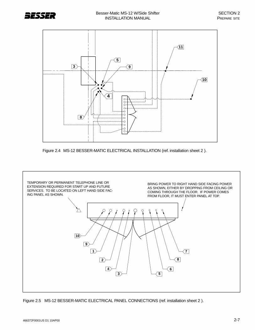
Refer to figure 2.4 and Installation drawing sheet 2 forelectrical installations.
1. Locate position of all electrical stub-ups and positionof panel.
Note: All stub-up locations are shown in figure 2.4 andon the BESSER-MATIC installation print sheet 2.See the BESSER-MATIC foundation print for exactlocation under the panel and exact locations of theaccumulators.
a. Temporary or permanent telephone line or exten-sion required for start up and future service. To belocated near panel.
b. Bring power to the right hand side either by drop-ping from ceiling or coming through floor. If powercomes from floor, it must enter panel at top. Makeconnection using “quick disconnects” as describedbelow:
Note: Numbers 1 through 10 below refer to numbers infigures 2.4,and 2.5 and and installation drawingsheet 2.
1. 3/4” [19mm] conduit from the panel to theRackveyor
2. 1 1/4” [31.8mm] conduit from the panel to the valvestand.
3. 2” [50.8mm] conduit for control wiring from panel toloader Accumulator location.
4. 3/4” [19mm] conduit for communication cable fromthe panel to Control Station.
5. 1 1/2” [38.1mm] conduit for power wiring frompanel to loader Accumulator.
6. 1 1/4” [31.8mm] conduit for wiring from the panel tothe Depalleter 1.
7. 1 1/4” [31.8mm] conduit for wiring from the panel tothe pallet return/rollover.
8. 1 1/4” [31.8mm] conduit for wiring from the panel tothe Depalleter 2.
9. 1 1/4” [31.8mm] conduit for wiring from the panel tolowerator.
10. 1/2” [12.7mm] conduit for wiring panel to the 70 GPM power unit.
Notes on the electrical panel:Service for the panel can be provided from over-head using the conduit size in the electrical table.
The wire bundle length should be determined at thetime of order. If, for unknown reasons the lengthneeds to change, please let Besser Company knowas soon as possible.
Note: You may use straight lines instead of the rectangu-lar coordinates shown in figure 2.4.
ATTENTION!To comply with articles 110-9 and 110-10 of the nationalelectrical code, American customers shall supply a branchcircuit protective device to feed this control. The protectivedevice shall have a short circuit interrupting rating of no lessthan the available short circuit current. Failure to do so couldresult in a rupture of the protective device while attempting toclear a fault. Besser Company recommends the use of pro-tective devices with interrupting ratings of no less than200,000 AMPS RMS symmetrical. See the electrical datachart on page 1-2 for recommended protection. [for cus-tomers outside the US, please check with your country'selectrical codes and make sure you comply with all laws con-cerning electrical devices.]
466372F0001US D1 10AP00
Besser-Matic MS-12 W/Side ShifterINSTALLATION MANUAL
2-7
SECTION 2PREPARE SITE
10
9
1
2
43 5
6
7
8
Figure 2.5 MS-12 BESSER-MATIC ELECTRICAL PANEL CONNECTIONS (ref. installation sheet 2 ).
Figure 2.4 MS-12 BESSER-MATIC ELECTRICAL INSTALLATION (ref. installation sheet 2 ).
TEMPORARY OR PERMANENT TELEPHONE LINE OREXTENSION REQUIRED FOR START UP AND FUTURESERVICES. TO BE LOCATED ON LEFT HAND SIDE FAC-ING PANEL AS SHOWN.
BRING POWER TO RIGHT HAND SIDE FACING POWERAS SHOWN, EITHER BY DROPPING FROM CEILING ORCOMING THROUGH THE FLOOR. IF POWER COMESFROM FLOOR, IT MUST ENTER PANEL AT TOP.
9
8
4
5
11
10
3

466372F0001US D1 10AP00
Besser-Matic MS-12 W/Side ShifterINSTALLATION MANUAL
2-8
SECTION 2PREPARE SITE
2.4 PREPARE HYDRAULIC SUPPLY TO THE MS-12
Refer to installation drawing sheet 2 for hydraulic installa-tions. There are two power units on the MS_12. Themain power unit unit is a 70 G.P.M. The second powerunit is a 20 G.P.M and serves for the Rack Conveyor only.
1. Locate position of all hydraulic stub-ups and positionof hydraulic power units. 70 G.P.M Power unit maybe installed in standard location.
a. All stub-up locations are shown in figure 2.6 and onthe BESSER-MATIC installation prints sheet 2.
b. All hydraulic tubing to be below concrete and stubup 3” [76mm] above floor. We recommend under-ground runs, but overhead is possible.
c. Tubing, conduit and conduit from stub-ups to equip-ment not supplied by Besser company.
d. Recommended hydraulic pressure is 850 P.S.I.
2. Numbers 51 to 54 below refer to numbers in figures2.6 and in installation prints sheet 2
51. 20 G.P.M POWER UNIT:3/4” [19.1mm] O.D. hydraulic tubing with 0.120wall, tube nut, and ferrule at each end. Fromvalve stand to unloader rail locks.
52. 70 G.P.M POWER UNIT:1” [25.4mm] O.D. hydraulic tubing with 0.120 wall,tube nut and ferrule at each end. From 70 G.P.Mpower unit to depalleter #1.
53. 70 G.P.M POWER UNIT:3/4” [19.1mm] O.D. hydraulic tubing with 0.120wall, tube nut and ferrule at each end. From 70G.P.M power unit to lowerator.
54. 70 G.P.M POWER UNIT:1” [25.4mm] O.D. hydraulic tubing with 0.120 wall,tube nut and ferrule at each end. From 70 G.P.Mpower unit to depalleter #2.
2.5 PLACE CONCRETE FLOORThe area around the BESSER-MATIC is at elevation 100’-0” [30480mm] (plant grade) except for the Side Shifter pit.
First layer of concrete thickness varies according to localsoil conditions. Must carry a load of 32,000 lbs [14545Kg]under each rail support and shim. Do not place secondlayer of concrete until rail gauge has been confirmed sub-sequent to fully loaded trial run. Refer to section 3 of thismanual and to sheets 7, 8 and 9 of the Installation draw-ings.

466372F0001US D1 10AP00
Besser-Matic MS-12 W/Side ShifterINSTALLATION MANUAL
2-9
SECTION 2PREPARE SITE
D
C L
A
CS
IDE
SH
IFT
ER
ACCUMULATORSCL
CL
CLCRAWLER
RAILS
PALLET RETURN
SLIDE SHAFT
C LS
UP
ER
PA
C
C DEPALLETER 1L
5' - 7"[1702mm]
CLRACKCONV.
TR
AN
SF
ER
CA
RC L
UN
LOA
DE
RC L
LOA
DE
RC L
CL
DA
TU
M B
DATUM A
5"[1
27m
m]
5"[1
27m
m]
C DEPALLETER 2L
8' - 0"[2438mm]
8' -
0"
[243
8mm
]
B
51
3' -
0"
[914
mm
]
3' -
0"
[914
mm
]
6"[1
52m
m]
6"[1
52m
m]
VIE
W A
VIE
W A
VIE
W A
53
54
3' -
0"
[914
mm
]
52
Figure 2.6 MS-12 BESSER-MATIC HYDRAULIC INSTALLATION (ref. installation print sheet 2 ).
NOTE: FOR ALL DIMENSIONSMARKED WITH A LETTER, SEE
INSTALLATION DRAWING

SECTION 2PREPARE SITE
Besser-Matic MS-12 W/Side ShifterINSTALLATION MANUAL
2-10 466372F0001US D1 10AP00
Figure 2.7 STANDARD LOCATION FOR HYDRAULIC VALVE STAND AND 20 G.P.M. POWER UNIT FOR RACK CONVEYOR (SEE INSTALLATION DRAWING FOR LOCATION).
2" typ. [51mm]
10" [254mm]
2" [51mm]
51
VALVE STAND
POWERUNIT
1' -0" [305mm]
Figure 2.8 REMOTE LOCATION FOR HYDRAULIC VALVE STAND AND 20 G.P.M. POWER UNIT FOR RACK CONVEYOR (SEE INSTALLATION DRAWING FOR LOCATION).
6"152
6"152TYP.
4' 7"1397
3"76
3' 0"914

466372F0001US D1 10AP00
Besser-Matic MS-12 W/Side ShifterINSTALLATION MANUAL
3-1
SECTION 3INSTALLATION
3.1 INSTALL SIDE SHIFTER AND CRAWLERRAILS
The Side Shifter and Crawler rails should be installedaccording to specifications presented in figures 3.1 to 3.9along with installation drawing sheets 3, 4 and 9.
3.1.1 Install rail anchorsRail anchors (item 1 in figure 3.6) should be secured with3/4” X 4-3/4” [19mm X 121mm] L. anchor stud, 3/4”[19mm] lockwasher and 3/4” [19mm] hex. nut. Railanchors should be installed at 4 foot [1219mm] intervalsalong all rail paths. Figure 3.1 shows the rail anchorassembly and figure 3.2 shows the depth and placementusing the anchor plate as a template, for drilling anchorbolt holes. Mark and drill anchor bolt holes with care andprecision. In order for rail gauge to be accurate, the holesfor rail anchors must be located within a tolerance of±1/16 inches [2mm].
3.1.2 Install shimsSpacer shims (2” X 6” [51mm X 152mm]) (item 2 in figure3.6) should be placed halfway between each anchor plateto support rails. Tackweld shims to rails after rails havebeen located. Optional shims may be used to obtain thecorrect elevation of the rails but are not required for cor-rect support. Shim thickness may vary according to floorelevations.
SECTION 3INSTALLATION
THE PRESENT SECTION EXPLAINS HOW TO INSTALL BESSER-MATIC MULTI-SPADE MS-12. IF YOU AREALSO INSTALLING A RACK TRANSPORTER SYSTEM SUCH AS A LSC-100,YOU SHOULD FOLLOWINSTRUCTIONS FOR BOTH THESE SYSTEMS SIMULTANEOUSLY. INSTRUCTION ON THE RACKTRANSPORTER SYSTEM INSTALLATION ARE FOUND IN MANUAL #466364F9601. USE THIS SECTIONCONJOINTLY WITH THE INSTALLATION DRAWING - (SHEETS 3 TO 10) TO INSTALL THE BESSER-MATICMS-12.THIS SECTION IS NOT A REPLACEMENT OF THE DRAWINGS LISTED ABOVE; IT IS PRESENTEDHERE AS COMPLEMENTARY INFORMATION.
WARNING: Use extreme care when handling heavy equipment.The MS-12 Besser-Matic is made oflarge and heavy parts that can become very dangerous when out of balance. Always use profes-sional riggers for moving and installing Besser-Matic frame and components. Also, any personnelworking or standing in the installation area should wear approved safety boots, hard hat and gog-gles. Work safely, think safety!
Figure 3.1 RAIL ANCHOR WITH SHIMS
SHIM IN EITHER LOCATION

466372F0001US D1 10AP00
Besser-Matic MS-12 W/Side ShifterINSTALLATION MANUAL
3-2
3.1.3 Install rails3.1.3.1 Side shifter rails. Side shifter rails are EB50T. Shim
rails to an elevation of 100’-0-1/4” [30486mm]. Referto item 1 in figure 3.6.
3.1.3.2 Crawler rails. Crawler rails are EB50T. Shim to anelevation of 100’-9-3/4” [30728mm]. Refer to item 2in figure 3.6.
3.1.3.3 Crawler rail curbs. Curbs have an elevation of101’-1 1/4” [30817mm]. Refer to item 3 in figure3.6.
3.1.3.4 Side Shifter actuators. They should be securedwith 1/2” X 3 3/4” L. [13mm X 95mm L.] anchorstud, 1/2” lockwasher and 1/2” hex. nut. Refer toitem 4 in figure 3.6
3.1.4 Install stop blocksWeld stop blocks (figure 3.3)(4 required - 1” high X 2”wide X 3” long ) [25.4mm X 51mm X 76mm]; one on eachend of Side Shifter rails to prevent Side Shifter from leav-ing rails. Refer to item 5 in figure 3.6.
3.1.5 Install cable & hose carrierLocate cable & hose carrier bracket and hose supportbracket (refer to item 6 in figure 3.6). Secure with 3/8” X 23/4” L. [9.5mm X 70mm L.] anchor studs, 3/8” lockwasherand 3/8” hex. nut.
Figure 3.2 ANCHOR BOLT Figure 3.3 STOP BLOCK
PLACE NUT ON ANCHORBOLT PRIOR TODRILLING
BOLT
ANCHOR PLATE
FLOOR LEVEL
DEPTH OF BOLT HOLES:4.5 X ANCHOR DIAMETER
STOP BLOCK
SECTION 3INSTALLATION

466372F0001US D1 10AP00
Besser-Matic MS-12 W/Side ShifterINSTALLATION MANUAL
3-3
3.1.6 Notch crawler railsNotch and shim crawler rails to match rails on Rackveyorfront section as shown below (also see item 12 in figure3.6). Then weld to front section.
Figure 3.4 NOTCHES ON CRAWLER RAILS
SECTION 3INSTALLATION
REFER TO INSTALLATION DRAWING FOR DIMENSIONS
15/16" [24mm] 15/16" [24mm]
2 3/4" [70mm]
15/16" [24mm]
15/16" [24mm]
CL
15/16" [24mm]

466372F0001US D1 10AP00
Besser-Matic MS-12 W/Side ShifterINSTALLATION MANUAL
3-4
SECTION 3INSTALLATION
Figure 3.5 SIDE SHIFTER AND CRAWLER ANCHOR PLATES AND SHIMS INSTALLATION.
4' - 7 1/4"[1403mm]
4' - 0"[1219mm]
2' - 0"[610mm]
4' - 7 1/4"[1403mm]
4' - 0"[1219mm]
2' - 0"[610mm]
8' - 1"[2464mm]
4' - 0"[1219mm]
2' - 0"[610mm]
1' - 4 3/8"[416mm]
MAY BE LESSTHAN 4'-0"[1219mm]
10 3/4" [273mm]
1' - 4 1/2"[417mm]
TRANSFER CARCL
CL
C LR
AC
K C
ON
V.
CR
AW
LER
RA
ILS
C L
SIDE SHIFTER
F
G
H
1
2
2
1
NOTE: FOR ALL DIMENSIONSMARKED WITH A LETTER, SEE
INSTALLATION DRAWING

466372F0001US D1 10AP00
Besser-Matic MS-12 W/Side ShifterINSTALLATION MANUAL
3-5
4' - 9"[1448mm]
4' - 9"[1448mm]
5 [127mm] 4' - 1 1/2"[1257mm]
4' - 0"[1219mm]
4' - 0"[1219mm]
7' -
7"
[231
1mm
]
14' -1 15/16" [4317mm]
12' - 0"[3658mm]
26' - 0"[7925mm]
+ 1/8- 0
7' -
31/3
2"
[431
7mm
]+ 1
/16
- 0
C L
C L
CL
CLTRANSFER CAR
CR
AW
LER
RA
ILS
RA
CK
CO
NV
.
SIDE SHIFTER
E
6
55
51
4
8
3
2
8
12 12
CLCAT TRACK
9' - 2 15/16"[2818mm]
RAIL GAUGE
SECTION 3INSTALLATION
Figure 3.6 SIDE SHIFTER AND CRAWLER RAIL INSTALLATION.
NOTE: FOR ALL DIMENSIONSMARKED WITH A LETTER, SEE
INSTALLATION DRAWING

466372F0001US D1 10AP00
Besser-Matic MS-12 W/Side ShifterINSTALLATION MANUAL
3-6
SECTION 3INSTALLATION
Figure 3.7 SIDE SHIFTER AND CRAWLER RAIL INSTALLATION.
14' - 1 15/16"
ELEVATION 99' - 5 1/2" [30515mm]
+1/8- 0 RAIL GAUGE
ELEV. 100' - 0" [30480mm]
7' - 31/32" [30515mm]
+1/16- 0
CLSIDE SHIFTER
7' - 9 1/2"[2375mm]
[4316mm]
7' - 7"[2311mm]
9 1/2" [241mm]
ELEV. 100' - 1/4" [30486mm]
ELEV. 100' - 3" [30556mm]
CRAWLER RAILSELEV. 100' - 9 3/4" [33452mm]
11
10
Figure 3.8 SIDE SHIFTER AND CRAWLER RAIL INSTALLATION.
6' - 0"
[1829mm]
1' - 8 15/16"
[520mm]
3' - 4 15/16"
[1040mm]
4' - 5 1/2"
[1358mm]
CLCRAWLER RAILS
6' - 0"[1829mm]
1' - 1 1/4"[337mm]
+1/8- 0
+1/16- 0
KILN FLOOR ELEV. 100' - 3" [30556mm]
CURB ELEV. 101' - 1 1/4" [30817mm]RAIL ELEV. 100' - 9 3/4" [30728mm]
3.1.7 Shim crawler railsAfter transfer car is in position, shim the leading ends ofall crawler rails to match crawler rails on transfer car, with-in .030” [0.75mm], then tackweld shims to rails. Shimthickness may vary according to floor elevations. Refer toitem 10 in figure 3.7 and items 8 in figure 3.6.
Note: Do not pour second layer of concrete until railgauge and elevation has been reconfirmed sub-sequent to fully loaded trial run. See item 11 infigure 3.7.

466372F0001US D1 10AP00
Besser-Matic MS-12 W/Side ShifterINSTALLATION MANUAL
3-7
SECTION 3INSTALLATION
Figure 3.9 LIFT ACCUMULATORS USING CRANE.
A
3.2 INSTALL ACCUMULATORS Locate Accumulators on steel foundation. Ensure thatAccumulators are plumb and straight before welding tosteel foundation. To lift Accumulators up, attach top ofAccumulators to crane with chain. Keep in mind accumu-lators are heavy, approximately 3600 Lbs [1636 Kg] each.To do so, bolt lift plates (A) to top of Accumulators. Seefigure 3.9.Note: Remove lift plates (A) before resuming instal-
lation.
WARNING: Accumulators are heavy!Inappropriate handling of this piece ofequipment could lead to serious injuries!Always use professional riggers.
466372F0001US D1 10AP00
Besser-Matic MS-12 W/Side ShifterINSTALLATION MANUAL
3-8
SECTION 3INSTALLATION
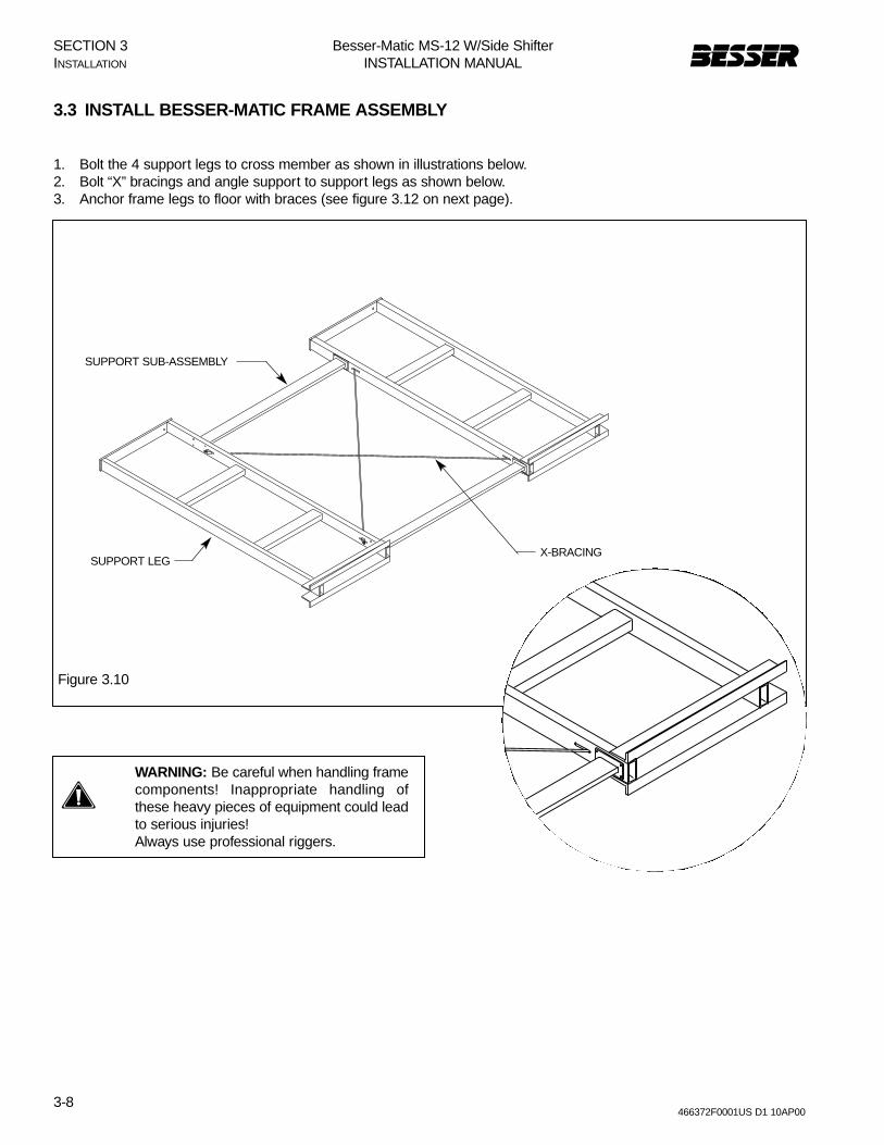
3.3 INSTALL BESSER-MATIC FRAME ASSEMBLY
1. Bolt the 4 support legs to cross member as shown in illustrations below.2. Bolt “X” bracings and angle support to support legs as shown below.3. Anchor frame legs to floor with braces (see figure 3.12 on next page).
WARNING: Be careful when handling framecomponents! Inappropriate handling ofthese heavy pieces of equipment could leadto serious injuries!Always use professional riggers.
Figure 3.10
SUPPORT SUB-ASSEMBLY
SUPPORT LEGX-BRACING

466372F0001U
S D
1 10AP
00
Besser-M
atic MS
-12 W/S
ide Shifter
INS
TALLAT
ION
MA
NU
AL
3-9
D (20.5 PALLET)E (18.5 PALLET)
F (20.5 PALLET)I (18.5 PALLET)
B
A
H 66.000" 66.000"
N
G
ML
C
KJ
RA
CK
SR
AC
KS
AC
CU
MU
LA
TO
RS
AC
CU
MU
LATO
RS
TRACK
TRACK
SUPPORTSUB-ASSEMBLY
SWITCHACTUATOR
BRACE
BRACE
SWITCHACTUATOR
PLANT FLOOR
CABLE AND HOSE CARRIER
SUPPORT ANGLE
"X" BRACING
LOADER
UNLOADER
SPLICEPLATE
SE
CT
ION
3IN
STA
LLATIO
N
Figure 3.12
FR
AM
E A
SS
EM
BLY.
NO
TE:FO
R A
LL DIM
EN
SIO
NS
MA
RK
ED
WITH
A LE
TTER
,SE
EIN
STA
LLATIO
N D
RA
WIN
G
466372F0001US D1 10AP00
Besser-Matic MS-12 W/Side ShifterINSTALLATION MANUAL
3-10
SECTION 3INSTALLATION
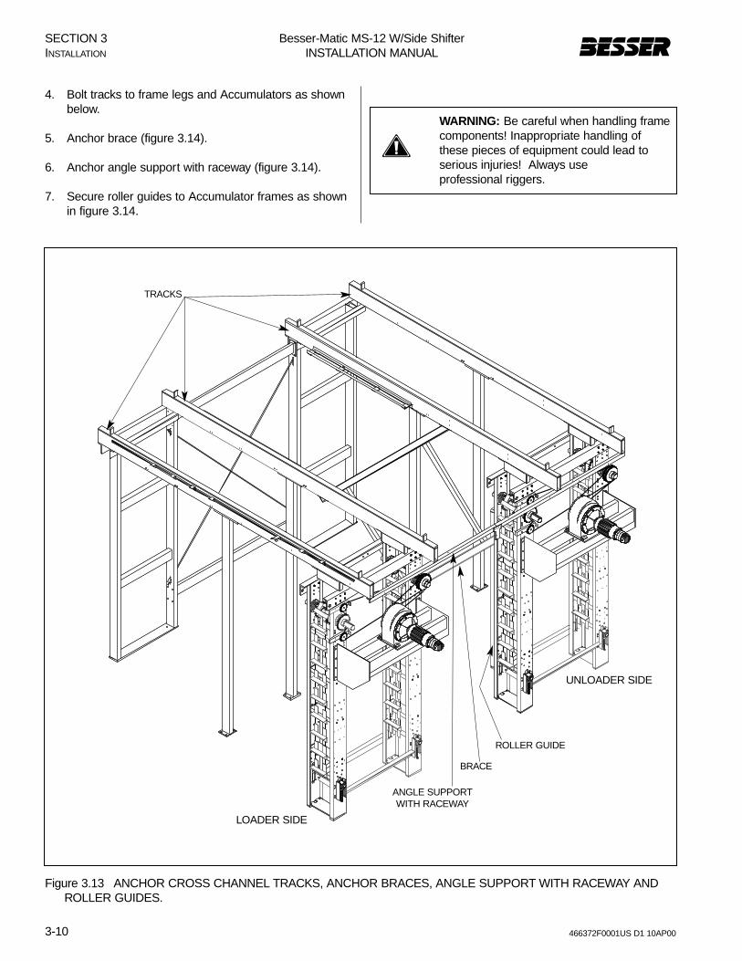
4. Bolt tracks to frame legs and Accumulators as shownbelow.
5. Anchor brace (figure 3.14).
6. Anchor angle support with raceway (figure 3.14).
7. Secure roller guides to Accumulator frames as shownin figure 3.14.
Figure 3.13 ANCHOR CROSS CHANNEL TRACKS, ANCHOR BRACES, ANGLE SUPPORT WITH RACEWAY AND ROLLER GUIDES.
WARNING: Be careful when handling framecomponents! Inappropriate handling ofthese pieces of equipment could lead toserious injuries! Always useprofessional riggers.
TRACKS
LOADER SIDE
UNLOADER SIDE
ANGLE SUPPORTWITH RACEWAY
BRACE
ROLLER GUIDE

466372F0001US D1 10AP00
Besser-Matic MS-12 W/Side ShifterINSTALLATION MANUAL
3-11
SECTION 3INSTALLATION

466372F0001US D1 10AP00
Besser-Matic MS-12 W/Side ShifterINSTALLATION MANUAL
3-12
SECTION 3INSTALLATION
Figure 3.15 INSTALLING STABILIZERS ON FRAME TRACKS.
3.4 INSTALL STABILIZERS AND LOWERSPADES
3.4.1 Install stabilizers.Install both Stabilizers on frame track. To do so, placeStabilizer on crane. Stabilizer can be lifted over framethen placed on tracks. See figure 3.15.
WARNING: Be careful when handling sta-bilizers! Inappropriate handling of thesepieces of equipment could lead to seriousinjuries! Always use professional riggers.
LIFT HERE
LIFT HERE

466372F0001US D1 10AP00
Besser-Matic MS-12 W/Side ShifterINSTALLATION MANUAL
3-13
SECTION 3INSTALLATION
Figure 3.16 ASSEMBLING LOWER SPADES TO STABILIZERS.
Figure 3.17 BOLTING SPADES.
3.4.2 Assemble lower spades.Before assembling each lower spade, carefully removepaint from all mating surfaces between stabilizers andspades. Assemble lower spade assemblies to stabilizers.To do so, place two 4” X 7.25 lbs X 36” channels [102mmX 3.3 Kg X 914mm] (figure 3.16 item A) between ballscrew nut and carriage side plate. Let bars stick out onboth sides of spade as shown in figure 3.18. Pick upspade sideways with fork lift truck, one fork on both sidesof spade, picking up on bars. It is important to chain thelower spade to the fork lift to ensure the lower spade doesnot tip over. Use a chain binder to tighten the chain. Careshould be taken not to get too close to limit switch or ballscrew with forks of lift truck.
3.4.3 Bolt Spade.Bolt Spade to Stabilizer with 6 bolts on each side at pointB in figure 3.17 below.
3.4.4 Weld spade.Obtain 900 angle between lower and upper unit of spadeand weld at points C in figure 3.17 below. Use 1/4”[6.35mm] welds.
A
FORKLIFT
CHAINHERE
B
C
WARNING: Be careful when handlingspades! Inappropriate handling of thesepieces of equipment could lead to seriousinjuries! Always use professional riggers.

466372F0001US D1 10AP00
Besser-Matic MS-12 W/Side ShifterINSTALLATION MANUAL
3-14
SECTION 3INSTALLATION
3.4.5 Center spadesCenter both spade assemblies with Accumulators asshown in figure 3.18. The shelves on the lower spadeshave to be centered with Accumulators. To adjust:
3.4.5.1 On all 4 wheels of each stabilizer, loosen set screwwhich holds the stabilizer wheel (figure 3.19) to thewheel shaft.
3.4.5.2 Move the stabilizer sideways until lower spadeshelves are centered with Accumulator. Wheels willnot move here, only stabilizer frame.
3.4.5.3 Tighten set screws in all 4 stabilizer wheels.
Figure 3.18 CENTERING SPADE ASSEMBLY.
Figure 3.19 STABILIZER WHEEL SCREWS.
ACCUMULATOR
CE
NT
ER
LIN
E
SPADE SHELVES(SHOWN HERE IN DOTTED LINE)
C L

466372F0001US D1 10AP00
Besser-Matic MS-12 W/Side ShifterINSTALLATION MANUAL
3-15
SECTION 3INSTALLATION
Figure 3.20 POSITION OF RACKVEYOR.
3.5 INSTALL RACKVEYOR
3.5.1 Position RackveyorLocate and position Rackveyor. First support frame mustbe aligned with center line of loader as shown in figure3.20. Square up Rackveyor to centerlines and shimRackveyor (under support frame) so that top of rollers areat 13-1/4” [337mm] from floor and match rails on SideShifter (elevation 100’-9-3/4” [30728mm]. Also the rails onRackveyor must be the same height as crawler rails (100’-9-3/4” [30728mm]).
3.5.2 Secure RackveyorSecure Rackveyor to floor with 3/4” X 7” L. [19mm X178mm] anchor studs, 3/4” lockwasher and 3/4” hex. nuts.
RACKVEYORCL
LOADERCL
RACKVEYOR
POSITION FIRST SUPPORTFRAME ON CENTER LINE OFLOADER

466372F0001US D1 10AP00
Besser-Matic MS-12 W/Side ShifterINSTALLATION MANUAL
3-16
Figure 3.21 POSITION OF SIDE SHIFTER AND RACKVEYOR.
3.6 INSTALL SIDE SHIFTER
3.6.1 Position Side ShifterPosition Side Shifter on rails with rail locks towardsBesser-Matic as shown in figure 3.21.
3.6.2 Install cat trackSecure cable and hose carrier to floor with 1/2” X 2 3/4” L.[13mm X 70mm L.] anchor studs, 1/2” lockwasher and1/2” hex. nut. as shown in figure 3.21.
SIDE SHIFTERRAIL LOCKS
SIDE SHIFTERCAT TRACK
RACKVEYOR
SIDE SHIFTER
SECTION 3INSTALLATION

466372F0001US D1 10AP00
Besser-Matic MS-12 W/Side ShifterINSTALLATION MANUAL
3-17
Figure 3.22 THE VALVE STAND.
3.7 INSTALL POWER UNIT AND VALVESTAND
3.7.1 Position power unit and valve standLocate Rackveyor power unit and valve stand (item 12 infigure 3.31). Secure to floor with 1/2” X 3 3/4” L. [12.7mmX 95.25mm L.] anchor studs, 1/2” lockwasher and 1/2”hex. nut.
3.7.2 Make hydraulic connectionsMake all hydraulic connections to valve stand (figure 3.22),power unit (figure 3.23), Side Shifter and Rackveyor.
3.7.2.1 3/4” [19.1mm] o.d. hydraulic tubing with .120 wall.tube nut and ferrule at each end from valve stand tocat track locks.
3.7.2.2 3/4” [19.1mm] o.d. hydraulic tubing with .120 wall-tube nut and ferrule at each end from valve stand toSide Shifter cat track.
3.7.2.3 3/4” [19.1mm] o.d. hydraulic tubing with .120 wall-tube nut and ferrule at each end from valve stand tocat track case drain.
3.7.3 Adjust speedRefer to section 6.2.6 for adjusting speed of Side Shifter,and Rackveyor
SIDE SHIFTER WHEELS
RETURN TO TANK
TO SIDE SHIFTER
TO PUMP (PRESSURE)
RACKVEYOR
SIDE SHIFTER LOCKS“A” = IN (RETRACT)“B” = OUT (EXTEND)
SECTION 3INSTALLATION

466372F0001US D1 10AP00
Besser-Matic MS-12 W/Side ShifterINSTALLATION MANUAL
3-18
WARNING
Figure 3.23 THE HYDRAULIC POWER UNIT.
3.8 FILL HYDRAULIC POWER UNITThe hydraulic power unit capacity is 40 gallons [151liters]. Use Shell Tellus 46 or equivalent. In order to fill thetank, power must must be available to operate the differ-ent hydraulic movement. Fill the system as follows:
1. Fill tank.2. Check pump rotation, as shown in figure 3.24, by
pushing starter in panel .3. Manually operate controls to fill the tank.
• Forward and reverse direction, side shifter;• Forward and reverse on Indexer;• Rail locks extend and retract.
4. Fill tank again and repeat until the full 40 gallon [151 liters] capacity is reached.
DRAIN
LEVEL
FILL
SECTION 3INSTALLATION
Figure 3.24 PUMP ROTATION.
CHECK ARROW HEREFOR CORRECT PUMPROTATION.

3.9 INSTALL THE CONVEYORSNote: Use figure 3.30 to locate conveyors.
3.9.1 Install front delivery conveyor.3.9.1.1 Depending on conveyor length, it may be necessary
to assemble conveyor together. If this is the case,locate splice plates and assemble conveyor togeth-er.
3.9.1.2 Position conveyor in line with Concrete ProductMachine (see item 1 in figure 3.31).
3.9.1.3 Bolt conveyor to loader Accumulator.
3.9.1.4 Bolt conveyor to floor (figure 3.27).
3.9.1.5 If necessary, hook up conveyor chains and tightenchains (for short conveyors, chains are not removedfrom the conveyor).
3.9.1.6 Adjust height of conveyor. Refer to figure 3.32,measurement H. Important: Height should betaken from floor to top of chain. Use adjustmentbolts to adjust conveyor height as shown in figure3.30.
3.9.1.7 Weld 1/2” sq. X 3” [13mm2 X 76mm] key to securelegs (figure 3.27).
3.9.2 Install unloading conveyor3.9.2.1 Depending on conveyor length, it may be necessary
to assemble conveyor together. If this is the case,locate splice plates (figure 3.25) and assemble con-veyor together.
3.9.2.2 Position conveyor in line with unloader center line(see item 4 in figure 3.31).
3.9.2.3 Bolt conveyor to unloader Accumulator as shown infigure 3.26.
3.9.2.4 Bolt conveyor to floor as shown in figure 3.27.
SECTION 3INSTALLATION
Besser-Matic MS-12 W/Side ShifterINSTALLATION MANUAL
3-19466372F0001US D1 10AP00
Figure 3.25 SPLICE PLATE.
Figure 3.26 CONVEYOR BOLTED TO ACCUMULATOR
Figure 3.27 ADJUSTABLE LEGS.
WELDED KEY
HEIGHT ADJUSTMENTBOLTS
ANCHOR HOLE

SECTION 3INSTALLATION
Besser-Matic MS-12 W/Side ShifterINSTALLATION MANUAL
3-20 466372F0001US D1 10AP00
3.9.2.5 If necessary, hook up conveyor chains and tightenchains (on short conveyors, chains are not removedfrom the conveyor).3.9.2.6Adjust height of conveyor.Refer to figure 3.32, measurement H. Important:Height should be taken from floor to top of chain.
3.9.2.6 Weld 1/2” sq. X 3” [13mm2 X 76mm] key to securelegs (figure 3.26).
3.9.3 Install pallet transfer stand3.9.3.1 Locate pallet transfer stand (item 4 in figure 3.31).on
center line of unloader and center line of palletreturn.
3.9.3.2 Adjust height so top of transfer conveyor rollers arethe same height as unloading conveyor.
3.9.3.3 Weld 1/2” sq. X 3” [13mm2 X 76mm] key to securelegs (figure 3.26).
3.9.3.4 Bolt pallet transfer stand to unloading conveyor asshown in figure 3.28.
3.9.3.5 Anchor pallet transfer stand to floor (figure 3.27).
3.9.4 Pallet rollover3.9.4.1 Connect rollover to hydraulic lines coming from
cuber. Refer to hydraulic diagram.
3.9.5 Install pallet return conveyor3.9.5.1 Assemble pallet return section of conveyor (item 7
in figure 3.31) and locate on center line of palletmagazine of Concrete Product Machine.
3.9.5.2 Bolt pallet return section to pallet transfer stand asshown in figure 3.29.
3.9.5.3 Bolt pallet return conveyor to Concrete ProductMachine.

466372F0001US D1 10AP00
Besser-Matic MS-12 W/Side ShifterINSTALLATION MANUAL
3-21
SECTION 3INSTALLATION
FRONT DELIVERY (LOADING)CONVEYOR
UNLOADINGCONVEYOR
PALLET ROLLOVER
PALLET RETURN
CONVEYOR
PALLET TRANSFER STAND
Figure 3.30 CONVEYORS ON MS-12. (Note that some drives are not shown on this illustration)

Besser-Matic MS-12 W/Side ShifterINSTALLATION MANUAL
SECTION 3INSTALLATION
CRAWLER RAILS
RACK CONVEYOR
ACCUMULATORS
SID
E S
HIF
TE
R
LOA
DE
R
UN
LOA
DE
R
CL
C L
C L
C L
C LPALLET RETURN
RA
CK
VE
YO
R
UN
LOA
DIN
G C
ON
V.
DE
PA
LLE
TE
R 2
CL
SP
AD
ES
.A
CC
UM
ULA
TO
RS F
RO
NT
DE
LIV
ER
Y
GR
AP
HIC
CO
NT
RO
L S
TA
TIO
N
CO
NC
. PR
OD
. MA
CH
INE
C L
CLSLIDE SHAFT
CL
AB
CD
E
FGST
AN
D
PO
WE
R U
NIT
VA
LVE
ST
AN
DC
AB
LE &
HO
SE
C
AR
RIE
R
DA
TU
M B
DATUM A
10
45
DE
PA
LLE
TE
R5
6
7
2
1
3
4
1112 12
3-22
Figure 3.31 OVERALL INSTALLATION DRAWING (TOP VIEW).
466372F0001US D1 10AP00
NOTE: FOR ALL DIMENSIONSMARKED WITH A LETTER, SEE
INSTALLATION DRAWING

Besser-Matic MS-12 W/Side ShifterINSTALLATION MANUAL
3-23466372F0001US D1 10AP00
SECTION 3INSTALLATION
Figure 3.32 OVERALL INSTALLATION DRAWING (ELEVATION VIEW).
CRAWLER RAILS
SLI
DE
SH
AF
TCO
NC
RE
TE
PR
OD
UC
TM
AC
HIN
E
C L
PLA
NT
FLO
OR
ELE
V. 1
00' -
0"[
3048
0mm
]
MA
CH
INE
BA
SE
PLA
TE
FR
ON
T D
ELI
VE
RY
CO
NV
EY
OR
LOA
DE
R &
UN
LOA
DE
R S
PA
DE
C LC L
C L
AC
CU
MU
LAT
OR
SR
AC
KV
EY
OR
A
B
CD
FG
E
H
J
I
NOTE: FOR ALL DIMENSIONSMARKED WITH A LETTER, SEE
INSTALLATION DRAWING
Besser-Matic MS-12 W/Side ShifterINSTALLATION MANUAL
3-24 466372F0001US D1 10AP00
SECTION 3INSTALLATION
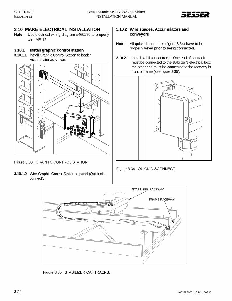
3.10 MAKE ELECTRICAL INSTALLATIONNote: Use electrical wiring diagram #469279 to properly
wire MS-12.
3.10.1 Install graphic control station3.10.1.1 Install Graphic Control Station to loader
Accumulator as shown.
3.10.1.2 Wire Graphic Control Station to panel (Quick dis-connect).
3.10.2 Wire spades, Accumulators and conveyors
Note: All quick disconnects (figure 3.34) have to beproperly wired prior to being connected.
3.10.2.1 Install stabilizer cat tracks. One end of cat trackmust be connected to the stabilizer’s electrical box;the other end must be connected to the raceway infront of frame (see figure 3.35).
Figure 3.33 GRAPHIC CONTROL STATION.
Figure 3.35 STABILIZER CAT TRACKS.
Figure 3.34 QUICK DISCONNECT.
STABILIZER RACEWAY
FRAME RACEWAY
Besser-Matic MS-12 W/Side ShifterINSTALLATION MANUAL
3-25466372F0001US D1 10AP00
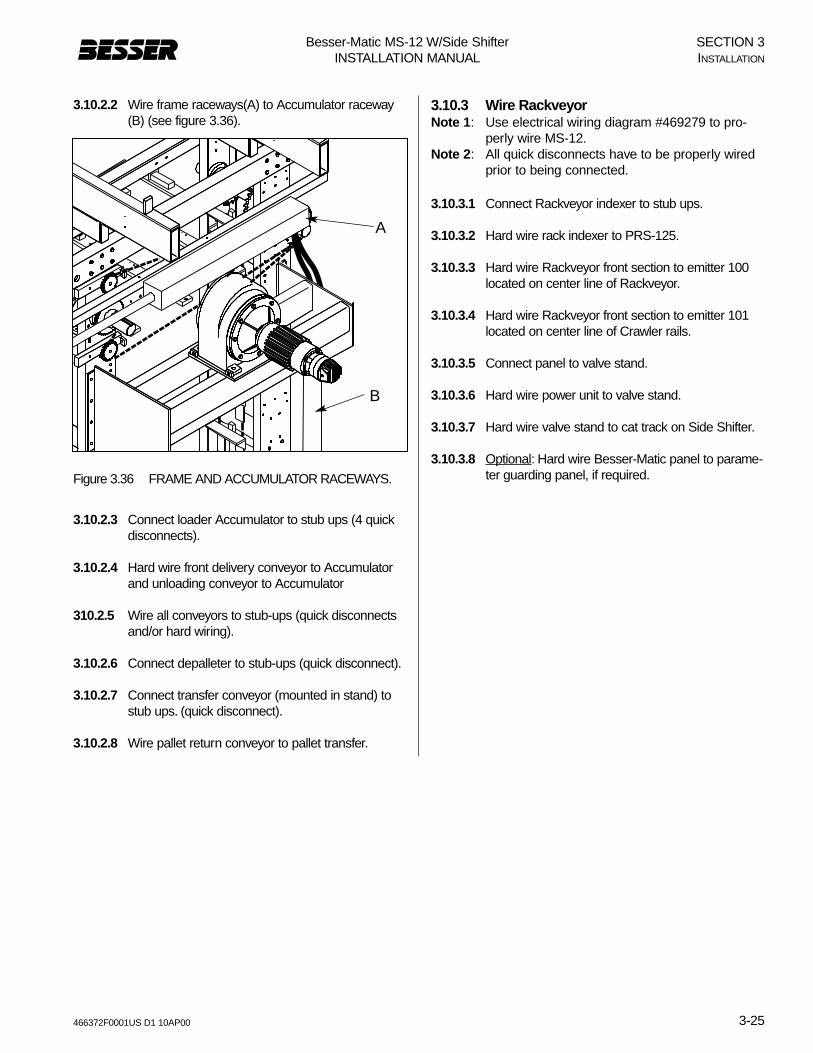
3.10.2.2 Wire frame raceways(A) to Accumulator raceway(B) (see figure 3.36).
3.10.2.3 Connect loader Accumulator to stub ups (4 quickdisconnects).
3.10.2.4 Hard wire front delivery conveyor to Accumulatorand unloading conveyor to Accumulator
310.2.5 Wire all conveyors to stub-ups (quick disconnectsand/or hard wiring).
3.10.2.6 Connect depalleter to stub-ups (quick disconnect).
3.10.2.7 Connect transfer conveyor (mounted in stand) tostub ups. (quick disconnect).
3.10.2.8 Wire pallet return conveyor to pallet transfer.
3.10.3 Wire RackveyorNote 1: Use electrical wiring diagram #469279 to pro-
perly wire MS-12.Note 2: All quick disconnects have to be properly wired
prior to being connected.
3.10.3.1 Connect Rackveyor indexer to stub ups.
3.10.3.2 Hard wire rack indexer to PRS-125.
3.10.3.3 Hard wire Rackveyor front section to emitter 100located on center line of Rackveyor.
3.10.3.4 Hard wire Rackveyor front section to emitter 101located on center line of Crawler rails.
3.10.3.5 Connect panel to valve stand.
3.10.3.6 Hard wire power unit to valve stand.
3.10.3.7 Hard wire valve stand to cat track on Side Shifter.
3.10.3.8 Optional: Hard wire Besser-Matic panel to parame-ter guarding panel, if required.Figure 3.36 FRAME AND ACCUMULATOR RACEWAYS.
B
A
SECTION 3INSTALLATION

Besser-Matic MS-12 W/Side ShifterINSTALLATION MANUAL
3-26 466372F0001US D1 10AP00
SECTION 3INSTALLATION
3.11 INSTALL SAFETY GATES.Refer to figures below for safety gate locations.
WARNING: NEVER operate the Besser-Matic without the safety guards and safetygates properly installed and in workingcondition.
Figure 3.37 SAFETY GATE (R.H. SIDE SHOWN).
SAFETY GATE

Besser-Matic MS-12 W/Side ShifterINSTALLATION MANUAL
3-27466372F0001US D1 10AP00
3.12 SECURE FRAME ASSEMBLYAfter the installation is complete and frame is levelled toproper dimensions, frame assembly must be secured asfollows:
3.12.1 Anchor frame.Anchor frame to plant structure with 4 angles (“Z”). Also,install brace and anchor to floor at point “S” and weld atpoint “R”.
3.12.2 Weld frameFrame and actuators should be straight and plumb andwelded at points “W” as shown in figure 3.38 below.
S
W
R
WWW
Figure 3.38 SECURE FRAME ASSEMBLY.
SECTION 3INSTALLATION

Besser-Matic MS-12 W/Side ShifterINSTALLATION MANUAL
3-28 466372F0001US D1 10AP00
3.13 CHECK LIST
After installation is complete, use the list below to verifyall components on the Besser-Matic.
Machines should be properly installed according tosection 3.1 to 3.9 of this manual.
Machines should be aligned, square and leveled.
Leg extension on conveyors should be welded andanchored to floor at correct elevation.
Power unit should be wired, filled up and ready to func-tion.
All hydraulic fittings/hoses should be tightened.
All reducers should be filled with oil (seemaintenance section).
Check all bolts and chains. They should be tightenedto proper tension.
Verify electrical panel is wired.
Graphic Control Station should be wired and workingproperly (section 5).
Verify all switches are wired and working properly (sec-tion 5).
Make sure safety gates and guards are in place.
Turn power ON
Verify all motors are running in correct direction.
Verify inputs and outputs. Use Graphic Control Station- section 5.
SECTION 3INSTALLATION