Embed Size (px)
Citation preview

PREPARATORY SURVEY REPORT ON
THE PROJECT FOR
REHABILITATION OF SUBSTATION AND TRANSMISSION LINE
IN KILIMANJARO REGION
IN
THE UNITED REPUBLIC OF TANZANIA
JANUARY 2011
JAPAN INTERNATIONAL COOPERATION AGENCY (JICA)
YACHIYO ENGINEERING CO., LTD.
Tanzania Electric Supply Company Ltd. (TANESCO) Ministry of Energy and Minerals The United Republic of Tanzania
IDD
JR
11-009

PREFACE
Japan International Cooperation Agency (JICA) decided to conduct the
preparatory survey on the project for Rehabilitation of Substation and Transmission
Line in Kilimanjaro Region in the United Republic of Tanzania, and organized a survey
team headed by Mr. Kyoji FUJII of Yachiyo Engineering Co., Ltd. between March
2010 and January 2011.
The survey team held a series of discussions with the officials concerned of the
Government of Tanzania, and conducted field investigations. As a result of further
studies in Japan, the present report was finalized.
I hope that this report will contribute to the promotion of the project and to the
enhancement of friendly relations between our two countries.
Finally, I wish to express my sincere appreciation to the officials concerned of the
Government of Tanzania for their close cooperation extended to the survey team.
January 2011
Kyoko KUWAJIMA
Director General,
Industrial Development Department
Japan International Cooperation Agency

SUMMARY

i
SUMMARY
① Overview of the Country
The United Republic of Tanzania (hereinafter referred to as "Tanzania") is situated in the eastern part of
the African continent; it has a total land area of approximately 945,000 km2 (roughly 2.5 times bigger
than Japan) and a population of some 42.48 million (2008, according to the World Bank). It is a unitary
republic that was formed by the amalgamation of Tanganyika on the mainland and the island of Zanzibar
in 1964.
Regarding the economy, Tanzania promoted a socialist economic policy after it gained independence in
1961. However, due to the effects of the subsequent oil crises, a war against Uganda and drought,
Tanzania fell into economic crisis in the 1980s, and from 1986 it promoted market-oriented economic
reforms under support from the World Bank and IMF. Since the latter part of the 1990s, Tanzania has
conducted solid macroeconomic management, and it experienced an economic growth rate of around 7
percent between 2002 and 2008.
Meanwhile, GNI per capita is low at US$400 (2009, according to the World Bank), and the major
challenge facing the Government of Tanzania concerns how to translate high economic growth into
reduction of poverty.
The major industries of Tanzania are agriculture (rice, maize and coffee, etc.), mining (gold and diamonds,
etc.), manufacturing (sisal hemp and tobacco, etc.) and tourism. In terms of sector-separate GDP,
agriculture accounts for the largest share with approximately 27 percent in 2008. However, the GDP ratio
of agriculture is declining every year, while the shares of mining, manufacturing and construction are
increasing.
In terms of fiscal management, Tanzania has a perennial fiscal deficit whereby expenditure exceeds
revenue. It is striving to cover the deficit with the help of assistance, however, it cannot fully compensate
for its excess in expenditure in this way. Accordingly, it is unable to independently finance the
construction and upgrading of large-scale public facilities and has no choice but to depend on assistance
from donors.
② Background of the Project
The Government of Tanzania embarked on structural reform of the electric power sector including the
breakup and privatization of TANESCO (Tanzania Electric Supply Company Limited) in 1993, however,
this led to a stagnation of public assistance including aid from donors in the sector. Until it was decided to
suspend the privatization of TANESCO in 2006, Tanzania was unable to conduct plant investment or
adequate maintenance of existing facilities in line with the growing demand for electricity, leading to the
serious deterioration of power supply facilities in the country. In response to this situation, the

ii
Government of Tanzania compiled the Electric Power System Master Plan (revised in 2009), geared to
long-term development of the power sector for 25 years up to 2033, and is promoting the development of
power sources and extension of transmission and transformation facilities on the national level based on
this plan.
Regarding power transmission and distribution networks in cities, JICA implemented the Study for
Rehabilitation of Distribution Facilities in Major Cities in Tanzania in 2002, and this resulted in
formulation of a 10-year master plan for improvement and expansion of transmission and distribution
facilities in the three cities of Dar es Salaam, Moshi (the capital of Kilimanjaro Region) and Arusha. The
Government of Tanzania is advancing improvement and expansion of the urban transmission and
distribution network based on this plan, however, progress has fallen far behind schedule due to the lack
of funds.
Kilimanjaro Region is the foremost tourist destination in Tanzania and constitutes an economic center
having a population of 1.57 million (2008). However, due to the low level of plant investment and
maintenance caused by the abovementioned failure of reform in the power sector, power supply is
frequently interrupted by rationing and equipment failures.
It was against such a background that the Government of Tanzania issued the request to the Government
of Japan for the upgrading and construction of transforming facilities and installation of 66 kV
transmission lines geared to achieving stable power supply in Kilimanjaro Region.
③ Outline of the study findings and Project contents
In response to the request, JICA dispatched the Study Team to Tanzania from April 13 to May 7, 2010
(first field survey) and from June 6 to July 3, 2010 (second field survey) in order to reconfirm the
contents of the request and discuss the contents for implementation with related agencies on the
Tanzanian side (responsible government agency: Ministry of Energy and Minerals (MEM), and
implementing agency: TANESCO), survey the Project sites and gather related materials and data.
On returning to Japan, the Study Team examined the necessity, social and economic impacts and validity
of the Project based on the field survey materials and compiled the findings into the draft preparatory
study report. Furthermore, JICA dispatched the Study Team to Tanzania for the third field survey (outline
explanations) from November 20 to December 1, 2010 in order to explain and discuss the draft
preparatory study report and reach a basic agreement with the Tanzanian counterparts.
The Project plan compiled based on the survey findings targets the upgrading of overloaded 33/11kV
substations and construction of new transmission and distribution lines and substations in areas
experiencing extreme voltage losses in Kilimanjaro Region.

iii
Outline of the Basic Plan Category Outline of Facilities
Equipment and
Materials Procurement
and Installation Works Plan
1. Procurement and installation of 33kV and 11kV distribution equipment and materials for upgrading of YMCA S/S (1) 33/11kV transformer (17MVA) (2) 33kV switchgear cubicle with circuit breaker (3) 33kV metering cubicle (4) 11kV switchgear cubicle (5) 33kV dead end pole (6) 11kV dead end pole (7) 33kV and 11kV cables (8) Earthing equipment (9) Outdoor lights (10) Equipment foundations etc.
2. Procurement and installation of 33kV and 11kV distribution equipment and materials for upgrading of Lawate S/S
(1) 33/11kV transformer (10MVA) (2) 33kV switchgear cubicle with circuit breaker (3) 33kV metering cubicle (4) 11kV switchgear cubicle (5) 33kV dead end pole (6) 11kV dead end pole (7) 33kV and 11kV cables (8) Earthing equipment (9) Outdoor lights (10) Equipment foundations etc.
3. Procurement and installation of 33kV and 11kV distribution equipment and materials for construction of KCMC S/S
(1) 33/11kV transformer (10MVA) (2) 33kV switchgear cubicle with circuit breaker (3) 33kV metering cubicle (4) 11kV switchgear cubicle (5) 33kV dead end pole (6) 11kV dead end pole (7) 33kV and 11kV cables (8) Earthing equipment (9) Outdoor lights (10) Equipment foundations etc.
4. Procurement and installation of 33kV distribution equipment and materials for expansion of Trade School S/S
(1) 33kV switchgear cubicle with circuit breaker (2) 33kV metering cubicle (3) 33kV dead end pole (4) 33kV cables (5) Earthing equipment (6) Equipment foundations etc.
5. Procurement and installation of 66kV receiving and 33kV distribution equipment and materials for construction of Makuyuni S/S
(1) 66kV switching equipment with frame (2) 66/33kV transformer (10MVA) (3) 33kV switchgear cubicle with circuit breaker (4) 33kV station transformer cubicle (5) Low voltage panel (6) Battery charger and battery (7) 66kV control and protection panels (8) 33kV control and protection panels (9) 33kV dead end pole
1 set 1 cubicle 1 cubicle 6 cubicles
1 set 3 sets 1 lot 1 lot 1 lot 1 lot
1 set 1 cubicle 1 cubicle 6 cubicles
1 set 3 sets 1 lot 1 lot 1 lot 1 lot
1 set 1 cubicle 1 cubicle 6 cubicles
1 set 3 sets 1 lot 1 lot 1 lot 1 lot
1 set 1 cubicle
1 set 1 lot 1 lot 1 lot
1 set 2 sets
6 cubicles 1 cubicle 1 cubicle
1 set 1 lot 1 lot 4 sets
iv
Category Outline of Facilities
Equipment and
Materials Procurement
and Installation Works Plan
(10) 33kV cables (11) Earthing equipment (including overhead earth wire) (12) Outdoor lights (13) Control building construction (300m2, 1F) (14) Equipment foundations etc.
6. Procurement and installation of 132kV receiving and 66kV transmission equipment and materials for expansion of Kiyungi S/S
(1) 132kV switching equipment with frame (2) 66kV switching equipment with frame (3) 132/66kV transformer (20MVA) (4) Low voltage panel (5) Battery charger and battery (6) 132kV control and protection panels (7) 66kV control and protection panels (8) 66kV cables (9) Earthing equipment (10) Control building construction (100m2, 1F) (11) Equipment foundations etc.
7. Construction of 66kV transmission line between Kiyungi~Makuyuni (approximately 34 km) (1) 66kV transmission line supports (steel towers) (2) Transmission line equipment and materials (conductors, insulators, earthing
equipment)
8. Construction of 33kV transmission line between Trade School~KCMC (approximately 5 km) (1) 33kV distribution line supports (wooden poles/steel poles) (2) Distribution line equipment and materials (conductors, insulators)
1 lot 1 lot 1 lot 1 set 1 lot
1 set 1 set 1 set
1 cubicle 1 set 1 set 1 set 1 lot 1 lot 1 set 1 lot
1 lot 1 lot
1 lot 1 lot
Equipment and
Materials Procurement
Plan
Procurement of the following equipment and materials (1) Spare parts for the procured equipment and materials (2) Maintenance tools
1 set 1 set
④ Project implementation schedule and cost estimation
In the event where the Project is implemented based on the Japan’s Grant Aid scheme, the total cost of the
Project will be (confidential). The contents and costs to be borne by the Tanzanian side will primarily be
provision of temporary road for construction of the 66kV transmission line (approximately 92 million
yen) and construction of 33kV distribution line (from Makuyuni S/S) (approximately 123 million yen).
The implementation schedule for the Project including the detailed design will be approximately 19
months.
(1) Relevance
The Project is deemed to be highly appropriate as an aid undertaking since it will aid realization of
development plans and energy policy in Tanzania and impart benefits for the general public of Tanzania.

v
(2) Efficiency
1) Quantitative effects
Indicator Current value (2010) Planned value (2013)
Restricted supply time 159 hours/month 32 hours/month
Time of power interruptions
due to failures
272 hours/month 190 hours/month
Voltage drop 11kV system (KCMC Hospital):
18% drop (11→9 kV)
0.4 kV system (Lombo): 16%
drop (0.4→0.338k V)
11kV system (KCMC Hospital):
No drop (11→11 kV)
0.4 kV system (Lombo):
5% drop (0.4→0.380 kV)
2) Qualitative effects
Indirect effects of the Project will be that it will contribute to the stable operation of hospitals and schools,
help improve the living environment for residents in the Project target area and help boost production in
factories and farms.
To sum up, since Project implementation can be expected to have major effects, it is confirmed to be
relevant for implementation under the Grant Aid scheme of the Government of Japan. Moreover, the
Tanzanian side is deemed to possess adequate personnel and budget for implementing the Project and
conducting operation and maintenance after implementation.

Contents
Preface
Summary
Location Map / Perspective
List of Figures & Tables
Abbreviations
Chapter 1 Background of the Project ............................................................................................. 1-1
1-1 Background of the Project ..................................................................................................... 1-1
1-2 Environmental and Social Consideration .............................................................................. 1-3
1-2-1 Systems and Procedures concerning Environmental Impact Assessment ..................... 1-3
1-2-2 Staging of Stakeholder Discussions ............................................................................... 1-7
1-2-3 Examination of Alternative Plans .................................................................................. 1-9
1-2-4 Land Acquisition Situation .......................................................................................... 1-11
1-2-5 Projected Impacts and Mitigation Measures ................................................................ 1-14
1-2-6 Environmental Check List and Envirionmental Monitoring Plan ............................... 1-17
1-2-5 Concerning Natural Environmen ................................................................................. 1-17
Chapter 2 Contents of the Project................................................................................................... 2-1
2-1 Basic Concept of the Project ................................................................................................. 2-1
2-1-1 Superior Objective and Project Targets ......................................................................... 2-1
2-1-2 Outline of the Project ..................................................................................................... 2-1
2-2 Out line Design of the Japanese Assistance .......................................................................... 2-1
2-2-1 Design Policy ................................................................................................................. 2-1
2-2-1-1 Basic Policy ........................................................................................................... 2-1
2-2-1-2 Policy regarding Social Conditions ........................................................................ 2-1
2-2-1-3 Policy regarding Social and Economic Conditions ................................................ 2-3
2-2-1-4 Policy regarding Execution Conditions ................................................................. 2-3
2-2-1-5 Policy regarding Utilization of Local Contractors, Equipment and Materials ....... 2-3
2-2-1-6 Policy regarding Maintenance Capacity of the Implementing Agency .................. 2-4
2-2-1-7 Policy regarding the Scope and Grading of Facilities and Equipment, etc. ........... 2-5
2-2-1-8 Policy regarding Works Methods, Procurement Methods and Works Schedule .... 2-6
2-2-2 Basic Plan ...................................................................................................................... 2-6
2-2-2-1 Overall Plan............................................................................................................ 2-6
2-2-2-2 Outline of the Basic Plan ..................................................................................... 2-10
2-2-2-3 Construction Plan and Equipment Plan ................................................................ 2-12
2-2-3 Outline Design Drawing .............................................................................................. 2-32
2-2-4 Implementation Plan .................................................................................................... 2-93
2-2-4-1 Implementation Policy ......................................................................................... 2-93
2-2-4-2 Implementation Conditions .................................................................................. 2-94

2-2-4-3 Scope of Works .................................................................................................... 2-95
2-2-4-4 Consultant Supervision ........................................................................................ 2-98
2-2-4-5 Quality Control Plan .......................................................................................... 2-101
2-2-4-6 Procurement Plan ............................................................................................... 2-102
2-2-4-7 Soft Component (Technical Assistance) Plan .................................................... 2-103
2-2-4-8 Implementation Schedule ................................................................................... 2-104
2-3 Obligations of recipient country ........................................................................................ 2-104
2-4 Project Operation Plan ...................................................................................................... 2-106
2-4-1 Basic Concept ............................................................................................................ 2-106
2-4-2 Operation and Maintenance Setup ............................................................................. 2-107
2-4-3 Periodic Inspection Items .......................................................................................... 2-107
2-4-4 Spare Parts Purchase Plan .......................................................................................... 2-109
2-5 Project Cost Estimation ..................................................................................................... 2-110
2-5-1 Initial Cost Estimation ............................................................................................... 2-110
2-5-2 Operation and Maintenance Cost ............................................................................... 2-111
2-6 Other Relevant Issues ........................................................................................................ 2-111
Chapter 3 Project Evaluation .......................................................................................................... 3-1
3-1 Recomendations .................................................................................................................... 3-1
3-1-1 Prerequisites for Project Implementation ...................................................................... 3-1
3-1-2 Prerequisites and External Conditions for Attaining the Overall project Plan .............. 3-1
3-2 Project Evaluation ................................................................................................................. 3-1
3-2-1 Relevance ....................................................................................................................... 3-1
3-2-2 Efficiency ....................................................................................................................... 3-3
[Appendices]
1. Member List of the Study Team
2. Study Schedule
3. List of Parties Concerned in the Recipient Country
4. Minutes of Discussions
5. Environment Impact Assessment Registration Form
6. Reporting letter on Screening decision
7. Scoping Report from MEM
8. Submission Report on Environmental and Socio Impact Assessment (ESIA)
9. Matrix of Entitlement
10. Example of an Agreement for Land Selling
11. Scoping Summary
12. Environmental Checklist for Power Transmission and Distribution Lines
13 Summary of Environmental and Social Monitoring Plan
14 Environmental Monitoring Form


Lawati S/S
KCMC S/S
Makuyuni S/S
Kiyungi S/S
YMCA S/S
KilimanjaroInternational Airport
ArushaAirport
Trade School S/S

The Project for Rehabilitation of Substation and Transmission Line in Kilimanjaro Region in the United Republic of Tanzania

List of Figures and Tables
Chapter 1
Figure 1-2-1.1 Outline of Environmental Administration Organization in Tanzania .............. 1-4
Figure 1-2-1.2 Conceptual View of Environmental Impact Assessment Procedure ................ 1-6
Figure 1-2-3.1 66kV Transmission Line Route ....................................................................... 1-10
Table 1-1.1 Contents of the Final Request and Results of Narrowing Down ..................... 1-2
Table 1-2-3.1 Outline of Alternative Routes for the 66kV Transmission Line ...................... 1-10
Table 1-2-4.1 Land Acquisition Situation for Each Project Component ................................ 1-13
Table 1-2-5.1 Scoping Results and Mitigation Measures ....................................................... 1-14
Chapter 2
Figure 2-2-1-2.1 Annual Rainfall in the Project Target Area Table ......................................... 2-2
Figure 2-2-1-2.2 Annual Number of Rainy Days in the Project Target Area ........................... 2-2
Figure 2-2-4-4-.1 Project Implementation Relationships ........................................................... 2-100
Figure 2-2-4-8.1 Project Implementation Schedule .................................................................. 2-104
Figure 2-4-1.1
Basic Thinking on Maintenance of Transmission, Distribution and
Transforming Facilities ..................................................................................
2-106
Table 2-2-1-7.1 Power Demand Forecast in Kilimanjaro Region by Each Substation ............ 2-5
Table 2-2-2-1.1 Climatic Conditions ....................................................................................... 2-6
Table 2-2-2-1.2 Electrical Design Conditions ......................................................................... 2-7
Table 2-2-2-1.3
Clearance of Transmission and Distribution Line Conductors and
Supports .........................................................................................................
2-8
Table 2-2-2-2.1 Outline of the Basic Plan ............................................................................... 2-10
Table 2-2-2-3.1
Contents of Transforming and Distribution Equipment and Materials for
Upgrading of YMCA S/S ...............................................................................
2-13
Table 2-2-2-3.2 Outline Specifications of Major Equipment and Materials for YMCA S/S .. 2-13
Table 2-2-2-3.3
Contents of Transforming and Distribution Equipment and Materials for
Upgrading of Lawate S/S ...............................................................................
2-15
Table 2-2-2-3.4 Outline Specifications of Major Equipment and Materials for Lawate S/S ... 2-16
Table 2-2-2-3.7
Contents of Transforming and Distribution Equipment and Materials for
Upgrading of KCMC S/S ...............................................................................
2-17
Table 2-2-2-3.8 Outline Specifications of Major Equipment and Materials for KCMC S/S ... 2-18
Table 2-2-2-3.9
Contents of Transforming and Distribution Equipment and Materials for
Upgrading of Trade School S/S .....................................................................
2-19

Table 2-2-2-3.10
Outline Specifications of Major Equipment and Materials for Trade
School S/S .....................................................................................................
2-19
Table 2-2-2-3.11
Contents of Transforming and Distribution Equipment and Materials for
Upgrading of Makuyuni S/S ..........................................................................
2-21
Table 2-2-2-3.12
Outline Specifications of Major Equipment and Materials forMakuyuni
S/S ..................................................................................................................
2-21
Table 2-2-2-3.13
Contents of Transforming equipment and Materials for Expansion of
Kiyungi S/S ....................................................................................................
2-25
Table 2-2-2-3.14
Outline Specifications of Major Equipment and Materials for Kiyungi
S/S ..................................................................................................................
2-25
Table 2-2-2-3.15
Outline Specifications of Major Equipment and Materials for 66kV
Transmission Line between Kiyungi S/S and Makuyuni S/S ........................
2-28
Table 2-2-2-3.16
Outline Specifications of Major Equipment and Materials for 33kV
Distribution Line between Trade School S/S and KCMC S/S .......................
2-29
Table 2-2-2-3.17 Spare Parts and Maintenance Tools to be Procured in the Project................. 2-30
Table 2-2-4-3.1 Scope of Works on the Japanese and Tanzanian Sides .................................. 2-96
Table 2-2-4-4.2 Engineer Dispatch by the Contractor(s) ......................................................... 2-101
Table 2-4-3.1 Periodic Inspection Items in Standard Equipment ......................................... 2-108
Chapter 3
Table 3-2-2.1 Breakdown of Patients at KCMC Hospital by Area (2009 actual figures) .... 3-6
Table 3-2-2.2 Ratio of Patients by Medical Department at KCMC Hospital ....................... 3-6

Abbreviations
AC Alternate Current
ACSR Alminium Conductor Steel Reinforced
DAC Development Assistance Committee
DC Direct Current
DoE Department of Environment
E/N Exchange of Notes
EDCF Economic Development Cooperation Fund
EIA Environmental Impact Assessment
EIS Environmental Impact Statement
EWURA Energy and Water Utility Regulatory Authority
G/A Grant Agreement
GCB Gas Circuit Breaker
GDP Gross Domestic Product
GNI Gross National Income
IEC International Electrotechnical Commission
IMF International Monetary Fund
IPP Independent Power Producer
ISO International Organization for Standardization
JCS Japanese Electrical Wire and Cable Maker's Association Standards
JEC Japanese Electrotechnical Committee
JEM Standards of Japan Electrical Manufacturer’s Association
JICA Japan International Cooperation Agency
JIS Japanese Industrial Standards
KCMC Kilimanjaro Christian Medical Centre
KIA Kilimanjaro International Airport
MEM Ministry of Energy and Minerals
NEAC National Environmental Advisory Committee
NEMC National Environmental Management Council
NPES National Poverty Eradication Strategy
NSGRP National Strategy for Growth and Reduction of Poverty
O&M Operation and Maintenance
OJT On the Job Training
ONAN Oil Natural Air Natural
OPGW Optical Grounding Wire
PCB Polychlorinated Biphenyl
PRS Poverty Reduction Strategy
ROW Right of Way
SCADA Supervisory Control and Data Acquisition System
TANESCO Tanzania Electric Supply Company Ltd.

TEDAP Tanzania Energy Development and Access Expansion Project
TOR Terms of Reference
TTS Telegraphic Transfer Selling rate
VCB Vacuum Circuit Breaker
YMCA Young Men's Christian Association
XLPE Cross-linked polyethylene

CHAPTER 1 BACKGROUND OF
THE PROJECT

1-1
Chapter 1 Background of the Project
1-1 Background of the Project
The United Republic of Tanzania has abundant natural resources such as gold and diamonds, etc. as
well as tourism resources such as Mount Kilimanjaro – the highest peak in Africa. Thanks to sound
macroeconomic management, it has achieved an economic growth rate of around 7 percent in recent
years. However, GNI per capita remains low at US$400 (2009, according to the World Bank), and the
majority of the population depends on agriculture, which accounts for roughly half of GDP.
Infrastructure development is essential in order to improve the living standard of citizens and promote
industry, however, Tanzania has particularly low rates of road dissemination and electrification among
East African countries, and this situation places a major constraint on social and economic
development and investment.
The Government of Tanzania embarked on structural reform of the electric power sector in 1993,
however, because this included the breakup and privatization of TANESCO (Tanzania Electric Supply
Company Limited), it led to a stagnation of public assistance including aid from donors in the sector.
Until it was decided to suspend the privatization of TANESCO in 2006, Tanzania was unable to
conduct plant investment or adequate maintenance of existing facilities in line with the growing
demand for electricity, leading to the serious deterioration of power supply facilities in the country. In
response to this situation, the Government of Tanzania compiled the Electric Power System Master
Plan (revised in 2009), geared to long-term development of the power sector for 25 years up to 2033,
and is promoting the development of power sources and extension of transmission and transformation
facilities on the national level based on this plan.
Regarding power transmission and distribution networks in cities, JICA implemented the Study for
Rehabilitation of Distribution Facilities in Major Cities in Tanzania in 2002, and this resulted in
formulation of a 10-year master plan for improvement and expansion of transmission and distribution
facilities in the three cities of Dar es Salaam, Moshi (the capital of Kilimanjaro Region) and Arusha.
The Government of Tanzania is advancing improvement and expansion of the urban transmission and
distribution network based on this plan, however, progress has fallen far behind schedule due to the
lack of funds.
Kilimanjaro Region is the foremost tourist destination in Tanzania and constitutes an economic center
having a population of 1.57 million (2008). However, due to the low level of plant investment and
maintenance caused by the abovementioned failure of reform in the power sector, power supply is
frequently interrupted by rationing and equipment failures. It was against such a background that the
Government of Tanzania issued the request to the Government of Japan for the upgrading and
construction of transforming facilities and installation of 66 kV transmission lines geared to achieving
stable power supply in Kilimanjaro Region.
Table 1-1.1 shows the results of evaluating the Project components based on assessment items such as
the urgency, relevance, necessity and beneficial effect, etc. according to the final requested contents

1-2
and analysis in Japan confirmed in the first field survey.
Table 1-1.1 Contents of the Final Request and Results of Evaluation
Contents of the final request (at time of first field survey) Results of evaluation Requested item Component details
Upgrading of YMCA Substation (S/S)
Upgrading of 33/11kV transformer (5MVA×1→17MVA×1)
Upgrading of 33kV and 11kV circuit breakers 33kV and 11kV cables, etc.
Target in the Project
Upgrading of Lawate S/S Upgrading of 33/11kV transformer (2.5MVA×1→10MVA×1)
Upgrading of 33kV and 11kV circuit breakers 33kV and 11kV cables, etc.
Construction of KCMC S/S Installation of 33/11kV transformer (5MVA×1) Installation of 33kV and 11kV circuit breakers 33kV and 11kV cables, etc.
Installation of circuit breaker at Trade School S/S
Installation of 33kV lead-out circuit breaker
Construction of 33kV transmission line between Trade School ~ KCMC S/S
Construction of 33kV distribution line over the following section: Trade School S/S ~KCMC S/S (3.7km)
Construction of Makuyuni S/S
Installation of 66/33kV transformer (10MVA×2) Installation of 66kV and 33kV circuit breakers 66kV and 33kV cables, etc.
Construction of 66kV transmission line between Kiyungi S/S~Makuyuni S/S
66kV transmission line: 34km 66kV circuit breaker (for transmission line lead-out)
Installation of transformer at Kiyungi S/S
Installation of 132/66kV transformer (20MVA×1) Installation of 132kV and 66kV circuit breakers
Construction of 33kV transmission line between KCMC and Gomberi
Construction of 33kV distribution line over the following section: KCMC S/S ~Gomberi S/S (4.9km)
Out of scope of the Project (not adopted)
Upgrading of Machame S/S Upgrading of 33/11kV transformer (2.5MVA×1→10MVA×1)
Upgrading of 33kV and 11kV circuit breakers 33kV and 11kV cables, etc.
Construction of Gomberi S/S Installation of transformer (10MVA×1) Installation of 33kV and 11kV circuit breakers 33kV and 11kV cables, etc.
Installation of circuit breaker at Same S/S
Installation of 132kV lead-in and lead-out circuit breakers
Construction of 33kV transmission line from Makuyuni S/S
Construction of 33kV distribution line over the following section (49km): Makuyuni~Mkuu Rombo Makuyuni~Kilema Makuyuni~Marangu Makuyuni~Himo town
Construction of Mkuu Rombo switching station
Installation of 33kV circuit breaker

1-3
1-2 Environmental and Social Consideration
1-2-1 Systems and Procedures concerning Environmental Impact Assessment
(1) Environmental Impact Assessment System
1) Environmental Law
The first environmental legislation to be introduced in Tanzania main land was the National
Environmental Management Act, No.19 of 1983, which marked the start of environmental
management controls in the country. In 1997, the National Environmental Policy was adopted
and the Draft EIA Guidelines and Procedure were formulated. This draft underwent revision in
2003, however, Tanzania still didn’t have a consistent legal system for enabling effective
environmental management. Accordingly, the Environmental Management Act, No.20 of 2004
was promulgated in 2004, and the Environmental Impact Assessment and Audit Regulations
were announced as the official document stance in 2005, thereby creating the current legal
system for environmental management. Features of this system are that it requires a registered
environmental expert to conduct environmental impact assessment, and it clearly stipulates that
stakeholder discussions should be held in the scoping stage so that opinions can be reflected in
projects. Moreover, the National Environmental Management Act (No. 19 of 1983) was
superseded by the Environmental Management Act (No.20 of 2004).
2) Environmental Management Implementing Agencies
The implementation setup for environmental management administration is prescribed in the
Environmental Management Act, according to which the Ministry of Environment under the
jurisdiction of the Office of the Vice President is responsible for environmental management and
conservation on the national level. The Ministry of Environment, which includes the National
Environmental Advisory Committee (NEAC), the Directorate of Environment (DoE) and the
National Environmental Management Council (NEMC), compiles and implements policies
related to environmental management and conservation.
① National Environmental Advisory Committee (NEAC):
This is the consultative body for the environment minister. It is composed of key figures in
specialist fields of environmental management in the public and private sectors and gives
recommendations and advice on all aspects of environmental administration.
② Directorate of Environment (DoE):
The DoE promotes the implementation of strategic environmental assessment in
development policy, projects and large-scale developments, gives advice to the government
on legal systems concerning compliance with international agreements on the environment,
and coordinates environmental items in sector-separate policies.

1-4
③ National Environmental Management Council (NEMC):
The NEMC conducts environmental impact assessment, ensures compliance and
implements review and monitoring of assessment; in addition it promotes public
participation in decisions that affect the environment.
These three agencies are responsible for environmental administration on the central government
level including coordination with other ministries and agencies. Concerning environmental
administration on the regional level, regional environmental Experts or environmental
management officers are appointed to each level of government. Figure 1-2-1.1 shows an outline
of environmental administration organizations in Tanzania.
Figure 1-2-1.1 Outline of Environmental Administration Organization in Tanzania
3) Activities Targeted for Environmental Impact Assessment
The activities targeted for environmental impact assessment, as prescribed in the Environmental
Impact Assessment and Audit Regulations, are divided into 22 sectors such as agriculture,
livestock farming, forestry and fisheries, etc. Projects that require environmental impact
assessment in the energy sector are as indicated below. The Project is thus eligible for
environmental impact assessment.
① Power generation, transmission and distribution, production and supply of gas, steam and
geothermal energy
② Storage of natural gas
③ Thermal power development (coal and nuclear power, etc.)
④ Hydropower generation
⑤ Development of other large-scale renewable and non-renewable energy resources
1-5
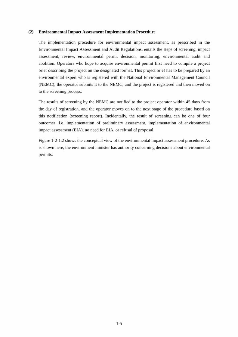
(2) Environmental Impact Assessment Implementation Procedure
The implementation procedure for environmental impact assessment, as prescribed in the
Environmental Impact Assessment and Audit Regulations, entails the steps of screening, impact
assessment, review, environmental permit decision, monitoring, environmental audit and
abolition. Operators who hope to acquire environmental permit first need to compile a project
brief describing the project on the designated format. This project brief has to be prepared by an
environmental expert who is registered with the National Environmental Management Council
(NEMC); the operator submits it to the NEMC, and the project is registered and then moved on
to the screening process.
The results of screening by the NEMC are notified to the project operator within 45 days from
the day of registration, and the operator moves on to the next stage of the procedure based on
this notification (screening report). Incidentally, the result of screening can be one of four
outcomes, i.e. implementation of preliminary assessment, implementation of environmental
impact assessment (EIA), no need for EIA, or refusal of proposal.
Figure 1-2-1.2 shows the conceptual view of the environmental impact assessment procedure. As
is shown here, the environment minister has authority concerning decisions about environmental
permits.

1-6
Figure 1-2-1.2 Conceptual View of Environmental Impact Assessment Procedure

1-7
(3) Environmental Impact Assessment Procedure in the Project
Concerning the environmental impact assessment procedure in the Project, TANESCO submitted
the EIA registration application with the project brief to the NEMC on June 4, 2010 (see the
attached EIA Registration Form). Based on this, the NEMC implemented the project screening
and notified the results to TANESCO on July 6 (see the attached Screening Report). The
Screening Report required TANESCO to implement an EIA, preceded by submission of a
scoping report and draft TOR concerning EIA implementation. In response, TANESCO
implemented a field survey, compiled a scoping report based on the findings and presented this
to NEMC on August 31. The NEMC gave its approval for the Scoping Report and attached the
draft TOR on September 9 (see the attached NEMC notification concerning the Scoping Report).
On receiving NEMC approval for the scoping and draft TOR, TANESCO embarked on the EIA
in September and completed field surveys for this by the end of November. TANESCO compiled
the results of the field surveys into the Environmental Impact Statement (EIS) and submitted this
to the NEMC on January 19, 2011 (see the attached document concerning submission of the
Environmental Impact Statement).
The results of review by the NEMC will be informed to TANESCO within 60 days of
submission. Since recommendations are usually appended to the notification of results,
TANESCO will amend the EIS according to the recommendations. Then the NEMC will conduct
another review of the EIS and refer it with its opinions to the environment minister with a view
to receiving environmental permission. The environment minister must make a decision within
30 days after receiving the results of review from the NEMC.
1-2-2 Staging of Stakeholder Discussions
Prior to registration of the Project with the NEMC, TANESCO conducted preliminary stakeholder
discussions targeting some of the residents of communities on the 66kV transmission line route in May
2010, and it incorporated the results of these discussions into the project brief. In the scoping work
that was implemented following the return of the screening findings by the NEMC, TANESCO
identified the major stakeholders and conducted stakeholder discussions with the Executive Director
of Moshi District Authority, the five villages on the transmission line route and the Tanganyika
Plantation Company. Furthermore, TANESCO has conducted discussions with all the stakeholders
during the EIA process and has strived to reflect as many opinions from residents and stakeholders as
possible into the Project.
The following table summarizes the main opinions that have been expressed in the stakeholder
discussions.

1-8
Opinion Response from
the Implementing Agency Executive Director of Moshi District Authority
- Since there is a shortage of land in Kilimanjaro region and it is very difficult to find alternative sites, particular caution will be required concerning the relocation and compensation of residents.
- There will be no relocation of residents. Concerning the acquisition of land for way-leave under the 66 kV transmission line, the District Authority Assessor, who is well-versed in the local land situation, will assess the contents and amount of compensation.
- Since rice paddies are important to the farmers of southern Moshi, the transmission line should be kept away from them as much as possible.
- Rice paddies will be avoided as much as possible.
- In order to stop people expecting too much compensation, the legal system should be clearly explained to local residents.
- Explanations will be given in stakeholder meetings with the target residents.
- In order to prevent trespassing on the transmission line right of way, compensation and construction should be implemented at the same time. Also, signs should be out up to warn trespassers.
- It is planned to start construction immediately after the payment of compensation. Moreover, boundary poles and signs will be established to indicate that way-leave is managed by TANESCO.
- In order to avoid future disputes over compensation, the district office or village offices should keep records of discussions with citizens and consensus reached over compensation.
- The District Office or Village Office will archive records of discussions with citizens and consensus reached over compensation. The EIA report will also be archived in the same way.
- In order to avoid unexpected and large compensation claims, TANESCO should bind agreements with village offices confirming that it will not expropriate land beyond the transmission line way leave.
- It shall be confirmed with village offices that land outside of way-leaves will not be expropriated in future, and agreements will be concluded regarding this.
Five affected villages
- The villages want the transmission line to avoid farmland.
- The transmission line route has been planned to avoid farmland and avert resident relocation as much as possible.
- It is desirable for TANESCO to maintain its relationship with residents throughout the entire Project period.
- TANESCO is striving to maintain good relations with residents and is also aware of the importance of good relations in the maintenance of facilities following Project completion.
- When constructing the substations and transmission line, employment opportunities should be offered to local farmers.
- The contractor will be encouraged to employ local farmers for jobs they can perform.
- Regarding compensation, money should be paid out fairly and promptly, and consideration should be given to the fact that it is difficult to secure alternative sites in Kilimanjaro region.
- The law requires the proper, fair and prompt payment of compensation. Moreover, the Assessor for Moshi District Authority has a thorough understanding of the land situation in Moshi District.
- Cultivation under the transmission line should be permitted as much as possible provided there are no problems.
- Although the law doesn’t recognize cultivation under transmission lines, it doesn’t oppose cultivation performed by people under their own responsibility. However, no compensation at all is provided for crops that need to be removed for maintenance work, etc.

1-9
Opinion Response from
the Implementing Agency - Since it is usually difficult to acquire land
equivalent to that expropriated with the compensation provided, the project operators should prepare alternative land nearby.
- Since compensation amounts are calculated in reference to actual land transactions, it is not difficult to purchase alternative land. Moreover, TANESCO will help secure alternative land if requested.
- In southern Moshi, since many farmers cultivate crops on leased land, compensation should be paid to both the lease holding farmers and landowners in order to avoid controversy.
- Compensation is paid to leaseholders for their crops, and to landowners for their land.
- Residents who are affected by the Project should be involved in all processes concerning land expropriation and compensation.
- TANESCO is striving to maintain good relations with residents both during the Project and after its completion.
Plantation Company
- When setting the interval between steel towers, take care to ensure that the transmission line doesn’t interfere with farm machinery.
- The location of transmission lines and steel towers will be decided in discussions with plantation owners. Since land under transmission lines will be owned by TANESCO as way-leave, farm machinery will not be operated there.
- Give the transmission line ample clearance off the ground and permit cultivation of sugar cane in the transmission line way leave.
- Ditto
- Decide the layout of steel towers inside the plantation upon conducting ample discussions with the plantation company.
- Although the law doesn’t recognize cultivation under transmission lines, it doesn’t oppose cultivation performed by people under their own responsibility. However, no compensation at all is provided for crops that need to be removed for maintenance work, etc.
1-2-3 Examination of Alternative Plans
With a view to optimizing the environmental and social impacts of the Project, examination was
conducted on the following options including the zero option.
Alternative 0: No Project implementation
Alternative 1: The transmission line route that was originally requested by TANESCO (August
2009)
Alternative 2: The transmission line route that was revised in the field survey that was jointly
implemented by TANESCO and the Study Team (route around villages)
As is indicated in Figure 1-2-3.1, the transmission line in Alternative 1 passes through a number of
villages and it is possible that residents will need to be relocated. For this reason, Alternative 2 was
drawn up with the goal of minimizing the impact on residents, and this entails no relocations.

1-10
Figure 1-2-3.1 66kV Transmission Line Route
Table 1-2-3.1 gives an outline of the alternative plans. Alternative 2 was deemed to be the most
feasible of the plans and was adopted as the Project route because it doesn’t entail the relocation of
residents.
Table 1-2-3.1 Outline of Alternative Routes for the 66kV Transmission Line Alternative 0 Alternative 1 Alternative 2
Explanation No project implementation
Originally requested route
Route avoiding villages
Total length - 32.6 km 32.7 km Benefits None Realization of stable
power supply, resulting improvement in public services and creation of employment, etc.
Same as in Alternative 1
Social and environmental impacts
None - A certain level of decrease in farm production (limited)
- Promotion of the local community through improvement in public services and creation of employment
Same as in Alternative 1
Impacts on the natural environment
None Possibility of minor impacts such as limited soil runoff, etc.
Same as in Alternative 1
Risk of pollution
None Minor possibility of limited air pollution due to operation of construction machinery
Same as in Alternative 1
Scale of land expropriation
None Required land: 652,000 m2
Required land: 654,000 m2
Relocation of residents
None Possibility that around 10 households will need to be relocated
None

1-11
1-2-4 Land Acquisition Situation
(1) TANESCO Land Acquisition Policy
In TEDAP, which is being implemented based on assistance from the World Bank, a resettlement
action plan in line with 132kV transmission lines has been compiled, and the following policies,
which meet the required criteria of the World Bank and Government of Tanzania, are indicated
regarding compensation for residents who are affected by the Project.
- Spreading information about the rights and choices of residents concerning relocation
- Presentation of relocation alternatives and consultation based on technical and economic
examination of feasibility
- Prompt implementation of compensation based on total substitution of losses
In the Project too, TANESCO is acquiring land based on this relocation and compensation policy
inherited from TEDAP. Specifically, out of the alternative routes for the 66 kV transmission line,
it has adopted the route proposed in Alternative 2, which doesn’t entail relocation of residents.
As a rule, land is acquired in return for cash compensation, although alternative land is
sometimes offered at the request of residents. When calculating the amount of compensation, the
following contents are taken into consideration (see the attached Matrix of Entitlement).
- Market price of real estate
- Loss of one’s living environment/cost of acquiring the target land
- Loss of profits or accommodation
- Disturbance allowance (4~6 percent of the real estate compensation amount)
- Transport allowance/capital expenditure incurred to the development of the subject land
The above-mentioned “Market price of real estate” refers to the market price for reacquiring
alternative real estate. In the case of buildings, this naturally includes the construction cost.
Moreover, the market price of real estate will be decided after the Authority Assessor conducts
hearing interviews with the Village Leaders in reference to the latest real estate transaction
records in the target area (see the attached sample land sale agreement) and past assessment
prices, while considering conditions of land use, soil, irrigation facilities and infrastructure in the
target area, distance from main roads, grade of adjoining roads, inflation and other factors.
If landowners are unhappy with the compensation amount proposed by the Authority Assessor,
they can lodge a complaint with the district authority Land Office. When this is received, the
Assessor is obliged to assess the target land once again. If the landowners are still unhappy with
the assessment, they can take the Assessor to court.

1-12
(2) Transmission Line Wayleave
Based on the Land Act (No. 4/1999), Village Land Act (No. 5/1999) and Electricity Act (2008),
land underneath transmission lines is expropriated by TANESCO as Wayleave (synonym for
ROW). Moreover, since the width of the way leave is not prescribed by law, it is decided
according to technical criteria of TANESCO. In the Project, the way leave for the 66kV
transmission line is prescribed as 20 m across and that for the 33kV distribution line is 10 m.
The transmission department of TANESCO normally has jurisdiction over the wayleave of
transmission lines, and it periodically patrols way leave in order to check for illegal occupation
and the amount of clearance. It sometimes consigns wayleave monitoring to village offices,
which look out for destructive activities and so on. Moreover, in stakeholder discussions
residents have requested that crop cultivation be allowed inside the wayleave, and while
TANESCO has responded by explaining that such cultivation is not allowed under the law, at the
same time it has indicated that field cultivation except for growing of tall fruit trees, etc. will be
allowed providing that farmers bear all risk (including that compensation will not be provided
even if crops need to be removed for maintenance and so on). It has maybe adopted this course
because, in the past, when all cultivation activities were prohibited in the way-leave, this led to
sabotage of the transmission lines by residents. Residents have responded favorably and given
their full understanding to this stance by TANESCO. Regarding the cultivation of crops inside
the wayleave, the practical solutions proposed above by TANESCO are thought to be
appropriate.
① So far TANESCO has not experienced any accidents resulting from cultivation inside the
wayleave.
② Since the minimum height of 66 kV transmission lines is 6.7 m above ground and the main
crops grown under lines are sugar cane and sweet corn, etc., there is no risk of crops
growing high enough to impede the transmission lines.
(3) Railway Lines
The 66kV transmission line in the Project will cross over a rail line (non-electrified) owned by
Tanzania Railway Limited. Passenger services on this line, which links Moshi and Tanga, were
abolished in 1992 and, although one freight train service ran back and forth over the line around
once a week after that, there are currently no train services at all after part of the line was washed
away by flooding in 2008. According to Tanzania Railway Limited, there are no plans to
improve this line or rehabilitate the parts damaged in the flooding. Even so, TANESCO has held
design discussions with Tanzania Railway Limited concerning the railway line crossing point
and secure permission for transmission line construction before the start of works. Tanzania
Railway Limited has orally given permission for the transmission line to cross the railway line,
and it is currently implementing procedures geared to the issue of an official document.
TANESCO has announced that it will obtain this written authorization to cross the railway line
before the start of work on the Project.

1-13
(4) Land Acquisition Situation regarding the Project
Apart from the land that has been newly acquired for the new substation at Mayukuni, there is no
need to acquire land for the upgrading and newly constructions of substations. Concerning the
new transmission line, work is currently being advanced on acquiring land for the way leave and
access roads (to be used as Temporary roads during construction). As for the 33kV distribution
line, since this will be constructed inside the ROWs of public roads, it will not be necessary to
acquire new land. Moreover, the Project will not entail relocation of residents or demolition of
buildings, and it won’t cause any replacement land and housing.
The following table shows the situation regarding land acquisition for each of the Project
components.
Table 1-2-4.1 Land Acquisition Situation for Each Project Component (as of the end of Jan. 2011)
Item Current land use / need for land
acquisition Landowner
Contents of compensation (Tsh) Status Site Access road
YMCA S/S
Existing S/S / Unnecessary
TANESCO Unnecessary Unnecessary ―
Lawate S/S
Existing S/S / Unnecessary
TANESCO Unnecessary Unnecessary ―
KCMC S/S
Farmland / Unnecessary
KCMC Unnecessary(given by KCMC)
Unnecessary ―
Trade School S/S
Existing S/S / Unnecessary
TANESCO Unnecessary Unnecessary ―
Makuyuni S/S
Farmland / Necessary
(11,398 m2 )
TANESCO(land has already
been acquired)
Land price:10,300,000
Disturbance allowance:
465,000
Crops compensation:
1,329,000
Total: 12,094,000
Unnecessary Completed
Kiyungi S/S
Existing S/S / Unnecessary
TANESCO Unnecessary Unnecessary ―
66kV transmission line
Farmland / Necessary
(654,000 m2)
Private Negotiations in progress
(Compensation is expected
to be finished by April 2011)
Negotiations in progress (Ditto)
Negotiations in progress
(Ditto)
33kV transmission line
Road / Unnecessary
TANROAD Unnecessary Unnecessary ―
Moreover, the temporary storage yard for use during the construction works will be located on land at

1-14
Kiyungi substation. It will thus not be necessary to acquire new land for this.
The Moshi District Land Office has informed landowners that land underneath the 66 kV transmission
line will be expropriated, and assessment is currently being implemented with a view to determining
the scope of the target land and the contents of compensation (there will be no removal of buildings or
relocation of residents in the Project). The District Authority Assessor who is affiliated to the Land
Office is currently assessing the value of land and crops based on applicable market prices and is
preparing a Valuation Report indicating the contents of compensation to each landowner.
The Valuation Report will be submitted for approval to the Assessor General of the Ministry of Lands,
Housing & Human Settlement Development. Once approval is given, the Authority Assessor will
prepare the Compensation Schedule indicating the contents of compensation for each plot of land and
notify this to TANESCO. Based on this, TANESCO will take budgetary steps and send funds covering
the total compensation amount to the District Land Office. The Land Office will show the
Compensation Schedule to the landowners, obtain their signatures and then make payments by check.
Once payments of compensation are finished, the Land Office will send copies of the signed
Compensation Schedule to TANESCO, legally paving the way for the transmission line works to be
started. TANESCO expects to complete payments of compensation arising from the 66 kV line by the
end of April 2011.
1-2-5 Projected Impacts and Mitigation Measures
Based on the JICA environmental and social consideration guidelines, scoping was carried out on the
feasible option (Alternative 2) in joint work with the TANESCO staff (including personnel in charge
of environmental matters) and JICA Survey Team (see the attached Scoping Summary).
In the Project, land will be newly acquired for the Mayukuni substation and the 66kV transmission line,
while site leveling will be implemented for the construction and upgrading of substation facilities and
transmission and distribution facilities, however, there are not expected to be any major environmental
or social impacts. The Project will not entail any major land reclamation or construction works close to
residential areas. The site leveling for construction of substations and transmission and distribution
lines will also be limited.
Table 1-2-5.1 shows the results of the scoping and the mitigation measures. Any negative impacts from
the Project can be minimized or avoided through implementing usual mitigation measures.

1-15
Table 1-2-5.1 Scoping Results and Mitigation Measures Environmental
Item Rating Explanation
Projected Mitigation Measures
Involuntary relocation of residents
D There will be no relocation of residents.
Local economy linked to employment and livelihood, etc.
B Expropriation of land for Mayukuni S/S and construction of the transmission line is expected to cause reduction of agricultural production. However, the affected area will be small and limited.
Survey of land use conditions and provision of appropriate and ample compensation
Land use and utilization of local resources
B The land used for constructing new S/S (Makuyuni and KCMC) will be converted from farmland.
Survey of land use conditions and provision of appropriate and ample compensation
Social capital and local decision making organizations, etc.
D No negative impacts are anticipated on social organizations.
Existing social infrastructure and social services
D No negative impacts are anticipated on social infrastructure and social services
Impoverished people, indigenous races and minorities
D Not applicable
Imbalance of damage and benefits
D Not applicable
Cultural heritage D Not applicable Local conflicts of interest
D Not applicable
Coordination of water rights and fishing rights, etc.
D Not applicable
Public hygiene D Not applicable Risk of infections such as HIV /AIDS, etc.
B A certain degree of risk of sexual infections caused by influx of workers during construction is forecast. However, since public education activities geared to preventing infection are frequently conducted in the target area, construction workers will be recruited from the local population, and the works are not large enough to require worker camps, the impacts will be limited.
Guidance on infection countermeasures to construction workers as required
Topography and geology
D Not applicable
Soil runoff B There is risk of soil runoff occurring on the new S/S construction sites (Mayukuni and KCMC) during construction.
Implementation of soil runoff prevention measures such as covering by waterproof sheet, etc.
Groundwater changes
D There are no construction works that will impact groundwater.
Water utilization D No negative impacts are anticipated on water use.

1-16
Environmental Item
Rating Explanation Projected Mitigation
Measures Coastal water bodies
D Not applicable
Biology and ecosystems
D Not applicable
Climate D Not applicable Landscape changes
D Since the transmission line is planned on the south side of the main road running from east to west, it will not detract from the view of Mount Kilimanjaro as a tourist resource on the north side of the road. Moreover, since there are no tourism resources at all on the south side of the road, there will be no damage to the local landscape.
Global warming B There is possibility that insulating material (SF6 gas) will leak from the circuit breakers to be installed at the new Mayukuni S/S. However, the possibility of this occurring will be very low.
Monitoring by gas leak detectors
Air pollution B Construction machinery will discharge exhaust gases during the construction period, however, because the scale of works will be limited, the quantities will be limited.
Appropriate maintenance of construction machines in order to secure total combustion of fuel
Water pollution B In the event of unexpected accidents, there is possibility that insulating oil will leak from transformers.
Thorough guidance to employees on how to deal with leaked insulating oil
Soil pollution B In the event of sudden accidents, there is a possibility that insulation oil used in transformers will leak.
Make sure that employees dispose of spilled insulation oil in the appropriate manner.
Solid waste B The transformer at YMCA S/S will be replaced, however, it is unclear whether or not PCB is used in this.
Inspection of old transformers. In cases where hazardous wastes such as PCB, etc. are generated, strictly collect, store and dispose according to the TANESCO guidelines.
Noise and vibration
B There is concern over noise and vibration caused by construction machinery during the construction period.
Prohibition of nighttime works in residential areas
Ground subsidence D Not applicable Odor D Not applicable Bottom sediment B In the event of unexpected accidents, there is
possibility that insulating oil will leak from transformers.
Thorough guidance to employees on how to deal with leaked insulating oil
Accidents B There is risk of construction laborers falling from high places or being electrocuted during the works.
Installation of warning signs, compulsory wearing of safety gear
[Note] A: Critical impacts are foreseen. B: Some impacts are foreseen. C: Degree of impact is unknown. D: Hardly any impact is expected

1-17
1-2-6 Environmental Check List and Environmental Monitoring Plan
TANESCO has compiled an environmental checklist (see the attached Environmental Checklist for
Power Transmission and Distribution Lines) and implements EIA and prepares monitoring plans based
on this.
The monitoring plan is contained in the Environmental Impact Explanation that was presented by
TANESCO to the NEMC (see the attached Environmental Monitoring Plan (extract from the
Environmental Impact Explanation)). The monitoring items, implementation setup and budget
indicated in this are deemed to be feasible contents because they are based on the experience of similar
projects, etc. previously implemented by TANESCO. Moreover, the budget for environmental
monitoring during the construction period is estimated to be approximately US$50,000.
This monitoring plan will be finalized upon undergoing review by the NEMC and following
amendment in response to indicated points.
Concerning the particularly important environmental impacts covered in the monitoring plan, the
results of monitoring will be regularly reported from TANESCO to JICA (see the attached Monitoring
Form). The important environmental impacts for which reporting to JICA is obligatory are leakage of
hydrocarbons (petroleum) and noise.
1-2-7 Concerning Natural Environment
The Project sites (substations and transmission line) are located inside farmland and plantations, and
they do not include or are located close to any part of national parks of protected areas. This point has
been confirmed by the responsible officer of the Kilimanjaro Regional Office of the Ministry of
Natural Resources & Tourism. Moreover, the Office has also confirmed that there are no rare species
of wildlife such as ICUN Red List registered fauna in and around the Project area.

CHAPTER 2 CONTENTS OF
THE PROJECT

2-1
2. Contents of the Project
2-1 Basic Concept of the Project
2-1-1 Superior Objective and Project Targets
In the National Strategy for Growth and Reduction of Poverty (NSGRP) that was compiled in July
2005, the following three-pronged basic strategy was prescribed in order to achieve growth and
poverty reduction: Strategy 1: Growth of the economy and reduction in income poverty, Strategy 2:
Improvement of quality of life and social well-being, and Strategy 3: Governance and accountability.
As a separate policy for realizing Strategy 1, ‘Provision of reliable and affordable energy to
consumers’ has been raised as a target.
Bearing in mind the said concept, the Project adopts the following superior objective: ‘To vitalize
social and economic activities in Kilimanjaro Region through providing stable power supply and
improving power supply reliability,’ and it has the following target: ‘To resolve power outages and
voltage drop problems in Kilimanjaro Region with a view to realizing stable power supply.’
2-1-2 Outline of the Project
In order to achieve the said objective and target, the Project intends to install and upgrade transmission,
distribution and transforming equipment and thereby stabilize power supply and improve the quality
of power in Kilimanjaro Region.
The assistance targets the upgrading of overloaded 33/11kV substations and construction of new
transmission and distribution lines and substations in areas experiencing extreme voltage losses.
2-2 Out line Design of the Japanese Assistance
2-2-1 Design Policy
2-2-1-1 Basic Policy
Based on the request to strengthen transmission and distribution facilities over almost the entire area
of Kilimanjaro Region in Tanzania, the Project aims to verify the necessity, appropriateness and
urgency of the request and satisfy the target power demand in Kilimanjaro Region in 2023 while
taking into account the assistance plans of other donors.
2-2-1-2 Policy regarding Social Conditions
(1) Temperature
The annual peak temperature in the target area over the past nine years (2000~2008) has been
33.6℃ on average, while the annual minimum temperature has been 16.2℃ on average.

2-2
According to figures for relative humidity in the 10-year period between 2000~2009, maximum
humidity has on average been 84.0 percent at six o’clock in the morning and 59.0 percent at
twelve o’clock noon. Thus, even though the target area is situated close to the Equator, the
year-round climate on average is warm and pleasant, reflecting the unique characteristics of
being located in the shadow of Mount Kilimanjaro at an altitude of approximately 890 m.
Bearing in mind the above temperature and relative humidity conditions, the transmission and
distribution facilities adopted in the Project shall be selected so that they operate normally and
incur no maintenance problems with respect to temporary temperature increases caused by the
outside air temperature and direct sunlight and high humidity.
(2) Rainfall and lightning
In the Project target area, as is shown in the figures for annual rainfall shown in Figure 2-2-1-2.1,
the annual average rainfall over the past 10 years has been 771.8 mm, although there have been
fluctuations from year to year. Moreover, as is shown in the number of rainy days per year in the
target area in the same figure, heavy rainfall is concentrated in the period between March and
May (the long rains) while there is lighter rainfall between November and January (the short
rains). In the Project, when designing the implementation plan, it will be necessary to pay ample
attention to the schedule of outside works, for example civil and building works accompanying
the installation of equipment.
Annual Numbers of Rainy Days (2000-2009)
0
5
10
15
20
Jan Feb Mar Apr May Jun Jul Aug Sep Oct Nov Dec
day
Mean Max
Source: Tanzania Meteorological Agency Source: Tanzania Meteorological Agency
Figure 2-2-1-2.1 Annual Rainfall in the Project
Target Area
Figure 2-2-1-2.2 Annual Number of Rainy Days
in the Project Target Area
There are no data concerning lightning strikes in the target area, however, local hearings found
that lightening does strike during the rainy seasons. Since there is risk of lightning striking steel
towers during construction of transmission lines, etc., it will be necessary to show ample
attention to the schedule of works that entail work in high places; moreover, it will be necessary
to install adequate protective equipment to guard against lightening infiltration on transmission
and distribution lines and in substations.
2000年~2009年の年間降雨量
0
200
400
600
800
1000
1200
1400
2000 2001 2002 2003 2004 2005 2006 2007 2008 2009
mm
Annual Rainfall (2000-2009)

2-3
(3) Wind
The average wind velocity in the Project area over the past 10 years (2000~2009) has been 10
knots (5 m/sec) on average, while a peak velocity of 16 knots (8 m/sec) has been measured. Peak
wind velocity of 23 knots (11.5 m/sec) has been measured in Same approximately 100 km away
from the target area. Therefore, although the target area is not impacted by the strong gusts
experienced by Dar es Salaam in the coastal region (maximum velocity 45 knots or 23.15 m/sec),
ample consideration shall be taken when designing transmission lines to ensure that they are
strong enough to withstand sudden gusts, etc.
(4) Salt damage
In the Project area, which is situated roughly 200 km from the nearest coastal point (Tanga),
there is no need to incorporate special salt damage steps in the equipment procurement and
installation.
2-2-1-3 Policy regarding Social and Economic Conditions
In the Project substation facility works, since power will need to be cut when switching between new
and existing facilities, it will be necessary to compile schedules that minimize impacts on consumers
and shorten the length of power outages.
When constructing the transmission and distribution lines, since this will entail cutting trees and
removing crops along routes and constructing access roads for works vehicles, it will be necessary to
select routes and compile schedules in a way that minimizes impacts. Moreover, when installing poles
and conducting excavation works, care will be needed to avoid impacts on telephone, water supply
and sewerage lines; and when conducting overhead line works, it will be necessary to certainly secure
safe clearance with existing distribution lines, telephone lines, rail lines and roads and strive for design
and execution activities that avert interference with existing infrastructure.
2-2-1-4 Policy regarding Execution Conditions
In Tanzania, medium and large-scale construction works for commercial facilities and office buildings,
etc. are routinely conducted and there are numerous general contractors and electrical works
companies that handle such works mainly in Dar es Salaam. Therefore, execution conditions are
relatively good.
2-2-1-5 Policy regarding Utilization of Local Contractors, Equipment and Materials
Interviews were conducted and materials were collected at a number of local companies concerning
the target scope of works and past works performance, etc. As a result, it was found to be relatively
easy to locally procure laborers, works vehicles and construction equipment and materials, etc. in

2-4
Tanzania. Moreover, judging from past jobs undertaken, since it is deemed possible to order general
work for substation construction, civil engineering works, building works and transmission and
distribution line construction works to local operators, the implementation plan shall be compiled
assuming utilization of local operators.
Moreover, in Tanzania it is possible to procure the wooden poles used in distribution line works and
the aggregate, cement and reinforcing bars, etc. used in civil engineering and building works.
Considering the nurturing of local industry, locally procurable equipment and materials shall be
adopted as much as possible, however, since equipment and materials for the scale of substations and
transmission and distribution facilities required in the Project are not manufactured in Tanzania, these
items shall be procured from Japan or third countries while considering the record of existing facilities
and maintenance capacity in Tanzania.
2-2-1-6 Policy regarding Maintenance Capacity of the Implementing Agency
Tanzania has experienced numerous power development projects of similar scale to the Project here
under Japanese Grant Aid and by other donors including the project to strengthen transmission and
distribution facilities in Dar es Salaam (completed in September 2010). Moreover, since the Tanzanian
side has operated and maintained the substation, transmission and distribution facilities supplied under
past Grant Aid, TANESCO, which will be in charge of Project facilities, will have the capability to
operate and maintain the substation, transmission and distribution facilities scheduled for procurement
and installation in the Project.
However, due to financial difficulties, TANESCO is unable to quickly renew existing deteriorated
substation, transmission and distribution facilities or procure expensive replacement parts and spare
parts that are in short supply, and this situation leads to overloading, electrical failures and power
outages. Moreover, since TANESCO does not conduct much training for engineers and operators, it
lacks engineers who possess know-how and technology concerning recent substation, transmission and
distribution facilities. As a result, in the Project, it will be necessary for Japanese engineers to conduct
OJT on operating and maintaining substation, transmission and distribution facilities during the works
period, to provide operation and maintenance manuals and to strive for the appropriate transfer of
operation and maintenance technology. Furthermore, the minimum required spare parts, testing
instruments and maintenance tools shall be supplied in order to facilitate the more effective and
efficient operation and maintenance of facilities.
Since 2009 JICA has been implementing a five-year technical cooperation project, namely the
Capacity Building Project for Efficient Transmission and Distribution Network (hereafter referred to
as the technical cooperation project). Since this aims to conduct technical training for TANESCO
engineers, electricians and technicians involved in transmission and distribution networks, prepare
training materials and nurture training instructors, and it also targets training of engineers from
regional branches, this will help enhance the capacity of TANESCO engineers to operate and maintain
the transmission and distribution facilities following completion of the Project.

2-5
2-2-1-7 Policy regarding the Scope and Grading of Facilities and Equipment, etc.
Considering the above conditions, the equipment and materials procured in the Project, the scope of
installation and the technical level of such equipment and materials shall be compiled based on the
following basic concept.
(1) Policy regarding the scope of facilities and equipment
In the Project, facilities for providing stable power to residents and public facilities in the target
area to meet the projected power demand in the target year of 2023 (10 years after the
completion of the Project) which is shown in Table 2-2-1-7.1 shall be constructed. The Japanese
side shall implement procurement and installation for the minimum required facilities, while the
Tanzanian side shall be responsible for the items that can be procured and installed by the
Tanzanian side. In this way care shall be taken to encourage the sustainable operation and
maintenance of power facilities on the Tanzanian side. Transformer capacity at KCMC is
planned so as to cover power demand at Gomberi substation which was initially requested but
finally became out of scope of the Project.
Table 2-2-1-7.1 Power demand forecast in Kilimanjaro region by each substation
Unit: MWEstimate
2005 2006 2007 2008 2009 2010 2011 2012 2013 2014 2015 2016 2017 2018 2019 2020 2021 2022 2023 2024
YMCA 4.0 4.0 5.6 5.6 4.9 5.3 5.8 6.4 5.6 6.1 6.7 7.4 8.1 8.8 9.7 10.6 11.6 12.7 14.0 15.3
Lawati 2.0 2.2 2.2 2.2 1.9 2.1 2.3 2.5 2.7 3.0 3.3 3.6 4.0 4.3 4.8 5.2 5.7 6.3 6.9 7.5
Machame 1.5 1.7 1.9 2.1 1.8 2.0 2.2 2.4 2.6 2.9 3.1 3.5 3.8 4.1 4.5 5.0 5.4 6.0 6.5 7.2
Boma Mbuzi 7.0 7.3 8.0 8.0 6.9 7.6 8.3 9.1 2.4 2.6 2.8 3.1 3.4 3.7 4.1 4.5 4.9 5.4 5.9 6.5
Trade School 4.9 5.5 6.6 7.0 6.1 6.6 7.3 8.0 7.3 8.0 8.8 9.7 10.6 11.6 12.7 13.9 15.3 16.7 18.3 20.1
Kiyungi 27.9 30.5 31.5 34.5 29.9 32.8 35.9 39.3 43.1 47.2 51.7 56.7 62.1 68.1 74.6 81.7 89.5 98.1 107.5 117.7
Mwanga 1.2 1.3 1.8 1.8 1.6 1.7 1.9 2.1 2.2 2.5 2.7 3.0 3.2 3.6 3.9 4.3 4.7 5.1 5.6 6.1
Same 1.5 1.6 1.6 2.0 1.7 1.9 2.1 2.3 2.5 2.7 3.0 3.3 3.6 3.9 4.3 4.7 5.2 5.7 6.2 6.8
KCMC 1.4 1.5 1.7 1.8 2.0 2.2 2.4 2.7 2.9 3.2 3.5 3.8
Gomberi 1.4 1.5 1.7 1.8 2.0 2.2 2.4 2.7 2.9 3.2 3.5 3.8
Makuyuni 7.6 8.4 9.2 10.0 11.0 12.0 13.2 14.5 15.8 17.4 19.0 20.8
K'njro Total 30.6 33.4 34.9 38.3 33.2 36.4 39.9 43.7 47.8 52.4 57.4 62.9 69.0 75.6 82.8 90.7 99.4 108.9 119.3 130.7
[Remarks] Substations to be upgraded or constructed under the Project Target
Growth rate 9.567% /year (Master Plan 2009 update) Year
Actual Forecast
Furthermore, in order to realize economical design, standard items of equipment and materials
that comply with international specifications shall be adopted as far as possible; moreover, the
minimum required composition and specifications shall be adopted while seeking compatibility
with existing equipment and instruments.
(2) Policy regarding grades
When designing the substation, transmission and distribution facilities for procurement and
installation in the Project, care shall be taken to comply with existing system composition and
TANESCO technical standards and works manuals and ensure that contents do not deviate from
the technical level of TANESCO, which will be in charge of operation and maintenance
following supply.

2-6
2-2-1-8 Policy regarding Works Methods, Procurement Methods and Works Schedule
In the Project, since numerous target sites are dispersed (substations) and construction of
approximately 5 km of distribution line and 34 km of transmission line shall be implemented
simultaneously, processes shall be planned so that work groups can be appropriately organized to
efficiently implement the works; moreover, it will be necessary to adopt works methods with which
the local operators and engineers are familiar and establish a works management setup to ensure that
the work progresses safely and quickly.
Since equipment and materials from Japan or third countries will be landed at Dar es Salaam Port and
then transported approximately 650 km overland, it will be necessary to give the utmost care to curing
and packing and take ample steps to ensure that items can be procured safely and certainly without
interfering with the surrounding traffic.
2-2-2 Basic Plan
2-2-2-1 Overall Plan
(1) Design Conditions
Design conditions to be applied to the Project are described as follows.
1) Climatic Conditions
Table 2-2-2-1.1 shows the climatic conditions that will be applied to the design of substations,
transmission and distribution facilities, buildings and foundations.
Table 2-2-2-1.1 Climatic Conditions
Region Kilimanjaro
Altitude Not more than 1,000m
Ambient Temperature
Maximum 40 degree C
Minimum 10 degree C
Mean 20 degree C
Maximum Humidity 85%
Max. Wind Velocity 32 knots (16m/s) (See Note 1)
Rainfall (Monthly Maximum) 500mm
Seismic Force Horizontal 0.1G
Soil Bearing Capacity 5 ton/m2
(Note)
1. Meteorological stations in Kilimanjaro region have meteorological data for the past 10 years
(2000~2009). The highest mean wind velocity in Moshi which was recorded for the past 10
years (from 2000 to 2009) was 16 knots (8 m/s). Therefore, the maximum wind velocity is
estimated to be 32 knots (16m/s), twice as high as the highest mean wind velocity.

2-7
2) Basic Electrical Design Conditions
Table 2-2-2-1.2 shows the basic conditions for design applicable to the substation, transmission
and distribution line facilities.
Table 2-2-2-1.2 Electrical Design Conditions
Item Transmission System Distribution System Station Service Power
Nominal Voltage 132kV 66kV 33kV 11kV 400-230V AC 110V DC
Maximum Voltage 145 kV 72kV 36kV 12kV 440-253V AC 125V DC
Frequency 50Hz N/A
Maximum Short Circuit
Capacity
25kA
(1sec.)
25kA
(1sec.)
16.5kA
(1sec.)
16.5kA
(1sec.) N/A
Lightning Impulse Withstand Voltage (LIWV)
650 kV 325kV 170kV 75kV N/A
Earthing System Effective Earthing System N/A
Minimum Creepage Distance of Insulator
25mm/kV (See Note 1) N/A
Minimum Clearance of Conductor
(See Note 2) N/A
Phase to Ground (mm) 1,700 1,000 500 300 N/A
Phase to Phase (mm) 2,800 1,800 900 600 N/A
Clearance and Way Leave (See Note 3)
Protection Class (IP) (See Note 4)
SCADA and Communication Systems
(See Note 5)
(Notes)
1. Since the Project sites are located about 200 km away from the coast, salt damage is negligible.
However, the Project sites are located in dusty area. Therefore, minimum creepage distance of insulator
for outdoor use is 25 mm/kV. Minimum creepage distance of insulator inside of switchgear cubicles is
16 mm/kV.
2. The minimum clearance of conductor for transmission and distribution line conductors and supports
shall be determined in accordance with relevant standards and regulations. The minimum clearance of
conductor for 33kV and 11kV switchgear cubicles shall be determined by manufacturer’s standards.
3. The height and clearance of transmission and distribution line conductors shall be determined in
accordance with the requirements of TANESCO, TANZANIA National Roads Agency and Moshi Rural
District Office, etc. as indicated in Table 2-2-2-1.3. However, in cases where special arrangement is
required, TANESCO shall consult with relevant parties to obtain necessary permission.
4. Protection classes (IP) for 33kV switchgear cubicles, 11kV switchgear cubicles, low voltage panels,
control panels and protection relay panels are as follows.
Outdoor: IP43, Indoor: IP20
5. SCADA (Supervisory Control and Data Acquisition) and communication systems (power line carrier
and/or other systems) for substations shall be designed and provided by TANESCO.

2-8
Table 2-2-2-1.3 Clearance of Transmission and Distribution Line Conductors and Supports
Item 66kV
transmission line
33kV distribution
line
11kV distribution
line
Height of Conductor
General Area (m) 6.7 6 6
Road (m) 8 6 6
Railway (m) 8 8 8
Waterway, Fairway (m) 8 6 6
Width of Way Leave (m) 20 10 5
Clearance between conductor and house (m) 4 3 3
Clearance between supporting structure and road center
Trunk Road (m) 30 30 30
Feeder Road (m) 25 25 25
Collector Road (m) 20 20 20
Community Road (m) 12.5 12.5 12.5
Clearance between supporting structure and railway (m) 30 30 30
3) Applicable Codes/Standards and Units
With regard to the Project design, relevant international standards such as IEC and ISO and
Japanese standards are applied to the major functions of equipment and facilities in conformity
with the existing electrical equipment and facilities in Tanzania.
- International Electrotechnical Commission (IEC): Applied to major functions of electrical
products in general
- International Standardization Organization (ISO): Applied to performance evaluation of
industrial products in general
- Japanese Industrial Standard (JIS): Applied to industrial products in general
- Japanese Electrotechnical Commission (JEC): Applied to electrical products in general
- Standards for Japan Electrical Manufacturer's Association (JEM): Same as above
- Japanese Electrical Wire and Cable Maker's Association (JCS): Applied to electric wire and
cables
- Relevant Technical Standards on Electrical Installation: Applied to electrical work in
general
(2) Facilities Layout Plan
1) Substation Facilities
The layout plans for the six substations to be upgraded, expanded or constructed in the Project
are described below.

2-9
The two substations targeted for upgrading (YMCA, Lawate) shall be constructed on land owned
by TANESCO adjacent to the existing substations.
Transforming equipment (33/11kV transformer, 33kV outdoor switchgear cubicle, 11kV
switchgear cubicle) shall be installed outdoors.
At the two substations targeted for expansion (Trade School and Kiyungi), equipment shall be
installed inside the existing substation and on adjacent land.
Concerning expansion of the Trade School substation, the 33kV outgoing feeder to the KCMC
substation to be constructed in the Project shall be branched off from the existing 33kV line, and
a 33kV switchgear cubicle shall be installed outdoors to send power to the 33kV distribution
line.
Concerning expansion of Kiyungi substation, transforming equipment (132/66kV 20MVA
transformer, 132 kV switchgear and 66kV switchgear) for transmitting 66kV to Makuyuni
substation to be constructed in the Project shall be additionally installed inside the substation. A
control building (approximately 100 m2) for housing the 132 kV switchgear and 66kV
switchgear control and protection panels shall be constructed.
Concerning the two substations (KCMC, Makuyuni) to be newly constructed, TANESCO shall
purchase the necessary construction sites from the landowners.
Concerning KCMC substation, transforming equipment (33/11kV transformer, 33kV outdoor
switchgear cubicle, 11kV switchgear cubicle) shall be installed outdoors.
Concerning Makuyuni substation, the transforming equipment (66/33kV 20MVA transformer,
66kV switchgear and 33kV outdoor switchgear cubicle) shall be installed outdoors. A control
building (approximately 300 m2) for housing the 66kV switchgear and 33kV switchgear cubicle
control and protection panels shall be constructed.
2) Transmission and distribution facilities
The layout plan for 66kV transmission lines and 33kV distribution lines to be constructed in the
Project shall be as described below.
Concerning the 66kV transmission line, a single line of approximately 34 km shall be
constructed from the 66kV transmission bay inside the existing Kiyungi substation to Makuyuni
substation, which will be constructed in the Project. The 66kV line shall generally pass through
flat land.
As for the 33kV distribution line, a single line of approximately 5 km shall be constructed from
the 33kV outdoor switchgear cubicle that will be installed inside the Trade School substation in
the Project to the KCMC substation, which will also be constructed in the Project. The 33kV
distribution line shall pass along roads in the suburban area.

2-10
2-2-2-2 Outline of the Basic Plan
Table 2-2-2-2.1 shows an outline of the basic plan of assistance compiled based on the findings of the
field surveys and results of discussions with the Tanzanian side.
Table 2-2-2-2.1 Outline of the Basic Plan
Category Outline of Facilities
Equipment and
Materials Procurement
and Installation Works Plan
1. Procurement and installation of 33kV and 11kV distribution equipment and materials for upgrading of YMCA S/S
(1) 33/11kV transformer (17MVA) (2) 33kV switchgear cubicle with circuit breaker (3) 33kV metering cubicle (4) 11kV switchgear cubicle (5) 33kV dead end pole (6) 11kV dead end pole (7) 33kV and 11kV cables (8) Earthing equipment (9) Outdoor lights (10) Equipment foundations etc.
2. Procurement and installation of 33kV and 11kV distribution equipment and materials for upgrading of Lawate S/S
(1) 33/11kV transformer (10MVA) (2) 33kV switchgear cubicle with circuit breaker (3) 33kV metering cubicle (4) 11kV switchgear cubicle (5) 33kV dead end pole (6) 11kV dead end pole (7) 33kV and 11kV cables (8) Earthing equipment (9) Outdoor lights (10) Equipment foundations etc.
3. Procurement and installation of 33kV and 11kV distribution equipment and materials for construction of KCMC S/S
(1) 33/11kV transformer (10MVA) (2) 33kV switchgear cubicle with circuit breaker (3) 33kV metering cubicle (4) 11kV switchgear cubicle (5) 33kV dead end pole (6) 11kV dead end pole (7) 33kV and 11kV cables (8) Earthing equipment (9) Outdoor lights (10) Equipment foundations etc.
4. Procurement and installation of 33kV distribution equipment and materials for expansion of Trade School S/S
(1) 33kV switchgear cubicle with circuit breaker (2) 33kV metering cubicle (3) 33kV dead end pole (4) 33kV cables (5) Earthing equipment (6) Equipment foundations etc.
5. Procurement and installation of 66kV receiving and 33kV distribution equipment and materials for construction of Makuyuni S/S
(1) 66kV switching equipment with frame (2) 66/33kV transformer (10MVA) (3) 33kV switchgear cubicle with circuit breaker (4) 33kV station transformer cubicle (5) Low voltage panel
1 set 1 cubicle 1 cubicle 6 cubicles
1 set 3 sets 1 lot 1 lot 1 lot 1 lot
1 set 1 cubicle 1 cubicle 6 cubicles
1 set 3 sets 1 lot 1 lot 1 lot 1 lot
1 set 1 cubicle 1 cubicle 6 cubicles
1 set 3 sets 1 lot 1 lot 1 lot 1 lot
1 set 1 cubicle
1 set 1 lot 1 lot 1 lot
1 set 2 sets
6 cubicles 1 cubicle 1 cubicle

2-11
Category Outline of Facilities
Equipment and
Materials Procurement
and Installation Works Plan
(6) Battery charger and battery (7) 66kV control and protection panels (8) 33kV control and protection panels (9) 33kV dead end pole (10) 33kV cables (11) Earthing equipment (including overhead earth wire) (12) Outdoor lights (13) Control building construction (300m2, 1F) (14) Equipment foundations etc.
6. Procurement and installation of 132kV receiving and 66kV transmission equipment and materials for expansion of Kiyungi S/S
(1) 132kV switching equipment with frame (2) 66kV switching equipment with frame (3) 132/66kV transformer (20MVA) (4) Low voltage panel (5) Battery charger and battery (6) 132kV control and protection panels (7) 66kV control and protection panels (8) 66kV cables (9) Earthing equipment (10) Control building construction (100m2, 1F) (11) Auxiliary civil engineering facilities (equipment foundations)
7. Construction of 66kV transmission line between Kiyungi~Makuyuni (approximately 34 km)
(1) 66kV transmission line supports (steel towers) (2) Transmission line equipment and materials (conductors, insulators, earthing
equipment)
8. Construction of 33kV distribution line between Trade School~KCMC (approximately 5 km)
(1) 33kV distribution line supports (wooden poles/steel poles) (2) Distribution line equipment and materials (conductors, insulators)
1 set 1 lot 1 lot 4 sets 1 lot 1 lot 1 lot 1 set 1 lot
1 set 1 set 1 set
1 cubicle 1 set 1 set 1 set 1 lot 1 lot 1 set 1 lot
1 lot 1 lot
1 lot 1 lot
Equipment and
Materials Procurement
Plan
Procurement of the following equipment and materials
(1) Spare parts for the procured equipment and materials (2) Maintenance tools
1 set 1 set

2-12
2-2-2-3 Construction Plan and Equipment Plan
(1) Upgrading of YMCA S/S
1) Basic Items
In order to upgrade the existing YMCA substation capacity (current transformer capacity is
5MVA) and the deteriorated 33kV switchgear equipment and 11kV switchgear cubicles, a new
YMCA substation (approximately 25 x 15 m) shall be constructed on land adjacent to the
existing substation.
One (1) new step down transformer (33/11kV, 17MVA), outdoor type 33kV/11kV switchgear
cubicles, one (1) set of 33kV dead end poles (33kV incoming) and three (3) sets of 11kV dead
end poles (11kV outgoing) shall be installed.
TANESCO shall execute the connection works from the 33kV receiving dead end poles to the
existing 33kV distribution line and from the 11kV dead end poles to the existing 11kV
distribution lines (3 lines).
Three feeders shall be used for drawing in the 11kV overhead distribution lines, and the circuit
breakers and cable sizes shall be designed upon considering peak current capacity per feeder of
5MVA.
33kV and 11kV cables of armored type shall be directly buried under the ground about 1.0 m
deep.
Low voltage and control cables shall be installed inside cable conduits.
The existing one (1) set of 33kV dead end poles (33kV incoming) and two (2) sets of 11kV dead
end poles (11kV outgoing), which will obstruct the works, shall be demolished by TANESCO.
To ensure that the existing YMCA substation does not experience power outage during the works,
the Japanese side shall procure temporary 33kV cables (approximately 90 m from the electric
pole outside of the substation to the gantry tower inside the substation), and the TANESCO side
shall install them.
2) Contents of the Plan
Table 2-2-2-3.1 shows the contents of transforming and distribution equipment and materials at
YMCA substation.

2-13
Table 2-2-2-3.1 Contents of Transforming and Distribution Equipment and Materials for Upgrading of
YMCA S/S No. Equipment Contents 1 33/11kV transformer Concerning the capacity and quantity of transformers, 17MVA x 1 set shall be
adopted based on the results of the power demand projection in 2023. Transformer equipped with on-load tap changer and having the same tap voltage as the existing transformer shall be adopted.
2 33kV switchgear cubicle with circuit breaker
In order to receive power from the 33kV overhead distribution line and feed it to the 33kV side, a receiving cubicle (1) equipped with 33kV circuit breaker (1 set) shall be installed outside. Considering the transformer capacity (17MVA), the rated current of the circuit breaker shall be 600A.
3 33kV metering cubicle If it isn’t possible to house the metering transformer (current transformer, voltage transformer), measuring instruments and protective relays inside the 33kV switchgear cubicle with circuit breaker, the 33kV metering cubicle shall be installed outdoors.
4 11kV switchgear cubicle Since the 11kV overhead distribution line has 3 outgoing lines, 3 feeders shall be adopted. Considering that the peak current capacity per feeder is 5MVA, the circuit breaker shall have a rated current of 600A. The 11kV switchgear cubicle shall comprise 6 cubicles, specifically 1 incoming feeder cubicle with circuit breaker, 3 outgoing feeder cubicles with circuit breakers, 1 station transformer and fuse cubicle and 1 battery/charger and distribution breaker cubicle, and these shall be installed outdoors.
5 33kV dead end pole Dead end poles (1 set) for receiving power from the 33kV overhead line shall be installed inside the YMCA S/S and shall be equipped with 33kV lightening arresters and line switch.
6 11kV dead end pole Dead end poles (3 sets) for distributing power from YMCA S/S to the 11kV overhead lines (3 lines) shall be installed and equipped with 11kV lightening arresters and line switch.
7 33kV and 11kV cables The 33kV cables shall be connected from the 33kV dead end poles to the transformers (33kV side) via the 33kV switchgear cubicle. The 11kV cables shall be connected from the transformers (11kV side) to the 11kV dead end pole (3 sets) via the 11kV switchgear cubicle. Also, the Japanese side shall procure approximately 90 m of temporary cable for connecting the electric pole outside of the S/S to the steel tower inside the S/S during the works period.
3) Outline Specifications of Major Equipment and Materials
Table 2-2-2-3.2 Outline Specifications of Major Equipment and Materials for YMCA S/S
No. Item / Equipment Specifications Quantity
1 33/11kV Transformer 1) Type 2) Rated primary voltage 3) Rated secondary voltage 4) Rated Capacity 5) Cooling type 6) Number of phases 7) Frequency 8) Tap voltage 9) Number of taps 10) Step voltage 11) Winding connection 12) Impedance
Outdoor, oil immersed, with on-load tap changer 33kV 11kV 17MVA ONAN 3 50Hz 33kV +10% to -10% 17 taps 1.25% Primary:Star (neutral lead out) Secondary:Star (neutral lead out) Third:Delta About 7%
1 set

2-14
No. Item / Equipment Specifications Quantity
2 33kV Switchgear Cubicle with Circuit Breaker 1) Type 2) Number of cubicles 3) Type of circuit breaker 4) Rated current 5) Rated short-time withstand
current
Outdoor cubicle Incoming feeder: 1 cubicle VCB or GCB (1 set) 600A 16.5kA (1 sec.)
1 cubicle
3 33kV Metering Cubicle 1) Type 2) Number of cubicles 3) Metering and protection
relays
Outdoor cubicle 1 cubicle Inside of metering cubicle (Remarks: This cubicle is required in case the metering
equipment and protective relays cannot be housed in the switchgear cubicle (fitted with circuit breaker)).
1 cubicle
4 11kV Switchgear Cubicle 1) Type 2) Number of cubicles 3) Type of circuit breaker 4) Rated current 5) Rated short-time withstand
current 6) Metering and protection
relays
Outdoor cubicle Incoming feeder: 1 cubicle (with circuit breaker) Outgoing feeder: 3 cubicles (with circuit breaker) Station transformer: 1 cubicle (with fuse) Battery and charger: 1 cubicle (with mold case circuit breaker) VCB or GCB (Incoming feeder: 1 set,
Outgoing feeder: 3 sets) Incoming feeder: 1,200A, Outgoing feeder: 600A 16.5kA (1 sec.) Inside of cubicles
6 cubicles
5 33kV Dead End Pole 1) Type 2) Equipment mounted on pole
Gantry type 33kV Lightning Arresters and Line Switch
1 set
6 11kV Dead End Pole 1) Type 2) Equipment mounted on pole
Gantry type 11kV Lightning Arresters and Line Switches
3 sets
7 33kV and 11kV Cables 1) Type 2) Conductor and insulation
Armored type cables directly buried under the ground Copper conductor and XLPE insulation
1 set
(2) Upgrading of Lawate S/S
1) Basic Items
In order to upgrade the existing Lawate substation capacity (current transformer capacity is
2.5MVA) and the deteriorated 33kV switchgear equipment and 11kV switchgear cubicles, a new
Lawate substation (approximately 30 x 18 m) shall be constructed on land adjacent to the
existing substation.
One (1) new step down transformer (33/11kV, 10MVA), outdoor type 33kV/11kV switchgear
cubicles, one (1) set of 33kV dead end poles (33kV incoming) and three (3) sets of 11kV dead
end poles (11kV outgoing) shall be installed.
TANESCO shall execute the connection works from the 33kV receiving dead end poles to the
existing 33kV distribution line and from the 11kV dead end poles to the existing 11kV
distribution lines (3 lines).

2-15
Three feeders shall be used for drawing in the 11kV overhead distribution lines, and the circuit
breakers and cable sizes shall be designed upon considering peak current capacity per feeder of
5MVA.
33kV and 11kV cables of armored type shall be directly buried under the ground about 1.0 m
deep.
Low voltage and control cables shall be installed inside cable conduits.
The earthing resistance of the substation site shall be designed as no more than 10 ohm.
2) Contents of the Plan
Table 2-2-2-3.3 shows the contents of transforming and distribution equipment and materials at
Lawate substation.
Table 2-2-2-3.3 Contents of Transforming and Distribution Equipment and Materials for Upgrading of
Lawate S/S No. Equipment Contents 1 33/11kV transformer Concerning the capacity and quantity of transformers, 10MVA x 1 set shall be
adopted based on the results of the power demand projection in 2023. Transformer equipped with on-load tap changer and having the same tap voltage as the existing transformer shall be adopted.
2 33kV switchgear cubicle with circuit breaker
In order to receive power from the 33kV overhead distribution line and feed it to the 33kV side, a receiving cubicle (1) equipped with 33kV circuit breaker (1 set) shall be installed outside. Considering the transformer capacity (10MVA), the rated current of the circuit breaker shall be 600A.
3 33kV metering cubicle If it isn’t possible to house the metering transformer (current transformer, voltage transformer), measuring instruments and protective relays inside the 33kV switchgear cubicle with circuit breaker, the 33kV metering cubicle shall be installed outdoors.
4 11kV switchgear cubicle Since the 11kV overhead distribution line has 3 outgoing lines, 3 feeders shall be adopted. Considering that the peak current capacity per feeder is 5MVA, the circuit breaker shall have a rated current of 600A. The 11kV switchgear cubicle shall comprise 6 cubicles, specifically 1 incoming feeder cubicle with circuit breaker, 3 outgoing feeder cubicles with circuit breakers, 1 station transformer and fuse cubicle and 1 battery/charger and distribution breaker cubicle, and these shall be installed outdoors.
5 33kV dead end pole Dead end poles (1 set) for receiving power from the 33kV overhead line shall be installed inside the Lawate S/S and shall be equipped with 33kV lightening arrester and line switch.
6 11kV dead end pole Dead end poles (3 sets) for distributing power from the Lawate S/S to the 11kV overhead lines (3 lines) shall be installed and equipped with 11kV lightening arresters and line switch.
7 33kV and 11kV cables The 33kV cables shall be connected from the 33kV dead end poles to the transformers (33kV side) via the 33kV switchgear cubicle. The 11kV cables shall be connected from the transformers (11kV side) to the 11kV dead end pole (3 sets) via the 11kV switchgear cubicle.

2-16
3) Outline Specifications of Major Equipment and Materials
Table 2-2-2-3.4 Outline Specifications of Major Equipment and Materials for Lawate S/S
No. Item / Equipment Specifications Quantity
1 33/11kV Transformer 1) Type 2) Rated primary voltage 3) Rated secondary voltage 4) Rated Capacity 5) Cooling type 6) Number of phases 7) Frequency 8) Tap voltage 9) Number of taps 10) Step voltage 11) Winding connection 12) Impedance
Outdoor, oil immersed, with on-load tap changer 33kV 11kV 10MVA ONAN 3 50Hz 33kV +10% to -10% 17 taps 1.25% Primary: Star (neutral lead out) Secondary: Star (neutral lead out) Third: Delta About 7%
1 set
2 33kV Switchgear Cubicle with Circuit Breaker 1) Type 2) Number of cubicles 3) Type of circuit breaker 4) Rated current 5) Rated short-time withstand
current
Outdoor cubicle Incoming feeder: 1 cubicle VCB or GCB (1 set) 600A 16.5kA (1 sec.)
1 cubicle
3 33kV Metering Cubicle 1) Type 2) Number of cubicles 3) Metering and protection
relays
Outdoor cubicle 1 cubicle Inside of metering cubicle (Remarks: This cubicle is required in case the metering
equipment and protective relays cannot be housed in the switchgear cubicle (fitted with circuit breaker)).
1 cubicle
4 11kV Switchgear Cubicle 1) Type 2) Number of cubicles 3) Type of circuit breaker 4) Rated current 5) Rated short-time withstand
current 6) Metering and protection
relays
Outdoor cubicle Incoming feeder: 1 cubicle (with circuit breaker) Outgoing feeder: 3 cubicles (with circuit breaker) Station transformer: 1 cubicle (with fuse) Battery and charger: 1 cubicle (with mold case circuit breaker) VCB or GCB (Incoming feeder: 1 set,
Outgoing feeder: 3 sets) Incoming feeder: 1,200A, Outgoing feeder: 600A 16.5kA (1 sec.) Inside of cubicles
6 cubicles
5 33kV Dead End Pole 1) Type 2) Equipment mounted on pole
Gantry type 33kV Lightning Arresters and Line Switch
1 set
6 11kV Dead End Pole 1) Type 2) Equipment mounted on pole
Gantry type 11kV Lightning Arresters and Line Switches
3 sets
7 33kV and 11kV Cables 1) Type 2) Conductor and insulation
Armored type cables directly buried under the ground Copper conductor and XLPE insulation
1 set

2-17
(3) Construction of KCMC S/S
1) Basic Items
Part of the land currently owned by KCMC Hospital shall be obtained, and KCMC substation
shall be constructed on a plot of this measuring approximately 30 x 30 m.
One (1) new step down transformer (33/11kV, 10MVA), outdoor type 33kV/11kV switchgear
cubicles, one (1) set of 33kV dead end poles (33kV incoming) and three (3) sets of 11kV dead
end poles (11kV outgoing) shall be installed.
The Japanese side shall install the 33kV distribution line from the Trade School substation to the
33kV incoming dead end pole, while the TANESCO side shall connect the 11kV dead end pole
to the existing 11kV distribution lines (3 lines).
Three feeders shall be used for drawing in the 11kV overhead distribution lines, and the circuit
breakers and cable sizes shall be designed upon considering peak current capacity per feeder of
5MVA.
33kV and 11kV cables of armored type shall be directly buried under the ground about 1.0 m
deep.
Low voltage and control cables shall be installed inside cable conduits.
The earthing resistance of the substation site shall be designed as no more than 10 ohm.
2) Contents of the Plan
Table 2-2-2-3.7 shows the contents of transforming and distribution equipment and materials at
KCMC substation.
Table 2-2-2-3.7 Contents of Transforming and Distribution Equipment and Materials for Upgrading of
KCMC S/S No. Equipment Contents 1 33/11kV transformer Concerning the capacity and quantity of transformers, 10MVA x 1 set shall be
adopted based on the results of the power demand projection in 2023. Transformer equipped with on-load tap changer and having the same tap voltage as the existing transformer shall be adopted.
2 33kV switchgear cubicle with circuit breaker
In order to receive power from the 33kV overhead distribution line and feed it to the 33kV side, a receiving cubicle (1) equipped with 33kV circuit breaker (1 set) shall be installed outside. Considering the transformer capacity (10MVA), the rated current of the circuit breaker shall be 600A.
3 33kV metering cubicle If it isn’t possible to house the metering transformer (current transformer, voltage transformer), measuring instruments and protective relays inside the 33kV switchgear cubicle with circuit breaker, the 33kV metering cubicle shall be installed outdoors.
4 11kV switchgear cubicle Since the 11kV overhead distribution line has 3 outgoing lines, 3 feeders shall be adopted. Considering that the peak current capacity per feeder is 5MVA, the circuit breaker shall have a rated current of 600A. The 11kV switchgear cubicle shall comprise 6 cubicles, specifically 1 incoming feeder cubicle with circuit breaker, 3 outgoing feeder cubicles with circuit breakers, 1 station transformer and fuse cubicle and 1 battery/charger and distribution breaker cubicle, and these shall be installed outdoors.

2-18
No. Equipment Contents 5 33kV dead end pole Dead end poles (1 set) for receiving power from the 33kV overhead line shall be
installed inside the KCMC S/S and shall be equipped with 33kV lightening arresters and line switch.
6 11kV dead end pole Dead end poles (3 sets) for distributing power from the KCMC S/S to the 11kV overhead lines (3 lines) shall be installed and equipped with 11kV lightening arresters and line switch.
7 33kV and 11kV cables The 33kV cables shall be connected from the 33kV dead end poles to the transformers (33kV side) via the 33kV switchgear cubicle. The 11kV cables shall be connected from the transformers (11kV side) to the 11kV dead end pole (3 sets) via the 11kV switchgear cubicle.
3) Outline Specifications of Major Equipment and Materials
Table 2-2-2-3.8 Outline Specifications of Major Equipment and Materials for KCMC S/S
No. Item / Equipment Specifications Quantity
1 33/11kV Transformer 1) Type 2) Rated primary voltage 3) Rated secondary voltage 4) Rated Capacity 5) Cooling type 6) Number of phases 7) Frequency 8) Tap voltage 9) Number of taps 10) Step voltage 11) Winding connection 12) Impedance
Outdoor, oil immersed, with on-load tap changer 33kV 11kV 10MVA ONAN 3 50Hz 33kV +10% to -10% 17 taps 1.25% Primary: Star (neutral lead out) Secondary: Star (neutral lead out) Third: Delta About 7%
1 set
2 33kV Switchgear Cubicle with Circuit Breaker
1) Type 2) Number of cubicles 3) Type of circuit breaker 4) Rated current 5) Rated short-time withstand
current
Outdoor cubicle Incoming feeder: 1 cubicle VCB or GCB (1 set) 600A 16.5kA (1 sec.)
1 cubicle
3 33kV Metering Cubicle 1) Type 2) Number of cubicles 3) Metering and protection
relays
Outdoor cubicle 1 cubicle Inside of metering cubicle (Remarks: This cubicle is required in case the metering
equipment and protective relays cannot be housed in the switchgear cubicle (fitted with circuit breaker)).
1 cubicle
4 11kV Switchgear Cubicle 1) Type 2) Number of cubicles 3) Type of circuit breaker 4) Rated current 5) Rated short-time withstand
current 6) Metering and protection
relays
Outdoor cubicle Incoming feeder: 1 cubicle (with circuit breaker) Outgoing feeder: 3 cubicles (with circuit breaker) Station transformer: 1 cubicle (with fuse) Battery and charger: 1 cubicle (with mold case circuit breaker) VCB or GCB (Incoming feeder: 1 set,
Outgoing feeder: 3 sets) Incoming feeder: 1,200A, Outgoing feeder: 600A 16.5kA (1 sec.) Inside of cubicles
6 cubicles

2-19
No. Item / Equipment Specifications Quantity
5 33kV Dead End Pole 1) Type 2) Equipment mounted on pole
Gantry type 33kV Lightning Arresters and Line Switch
1 set
6 11kV Dead End Pole 1) Type 2) Equipment mounted on pole
Gantry type 11kV Lightning Arresters and Line Switches
3 sets
7 33kV and 11kV Cables 1) Type 2) Conductor and insulation
Armored type cables directly buried under the ground Copper conductor and XLPE insulation
1 set
(4) Expansion of Trade School S/S
1) Basic Items
New outdoor type 33kV switchgear cubicles and one (1) set of 33kV dead end poles (33kV
outgoing feeder to KCMC substation) shall be installed at an area adjacent to the existing Trade
School, on a plot of land (approximately 9 x 8 m) that won’t interfere with the substation
upgrading plans compiled by TEDAP.
33kV underground cable shall connect the existing 33kV electric pole to the 33kV dead end
poles for outgoing feeder to KCMC S/S via the outdoor 33kV switchgear cubicle so that the
TEDAP plans for substation upgrading are not hindered. 33kV cables of armored type shall be
directly buried under the ground about 1.0 meter deep.
Earthing wire for new 33kV switchgear cubicle shall be connected to the existing earthing wires
of Trade School substation.
2) Contents of the Plan
Table 2-2-2-3.9 shows the contents of transforming and distribution equipment and materials at
Trade School substation.
Table 2-2-2-3.9 Contents of Transforming and Distribution Equipment and Materials for Upgrading of
Trade School S/S No. Equipment Contents 1 33kV switchgear cubicle
with circuit breaker In order to receive power from the 33kV overhead distribution line and feed it to the KCMC S/S, a receiving cubicle (1) equipped with 33kV circuit breaker (1 set) shall be installed outside. Considering the transformer capacity (10MVA) at KCMC S/S, the rated current of the circuit breaker shall be 600A.
2 33kV metering cubicle If it isn’t possible to house the metering transformer (current transformer, voltage transformer), measuring instruments and protective relays inside the 33kV switchgear cubicle with circuit breaker, the 33kV metering cubicle shall be installed outdoors.
3 33kV dead end pole Dead end poles (1 set) for feeding the 33kV overhead line to KCMC S/S shall be installed inside the Trade School S/S and shall be equipped with 33kV lightening arresters and line switch.
4 33kV cables The 33kV cables shall be connected from the existing electric pole to the 33kV dead end poles via the 33kV switchgear cubicle.

2-20
3) Outline Specifications of Major Equipment and Materials
Table 2-2-2-3.10 Outline Specifications of Major Equipment and Materials for Trade School S/S
No. Item / Equipment Specifications Quantity
1 33kV Switchgear Cubicle with Circuit Breaker 1) Type 2) Number of cubicle 3) Type of Circuit Breaker 4) Rated current 5) Rated short-time withstand
current
Outdoor cubicle Incoming feeder: 1 cubicle VCB or GCB (1 set) 600A 16.5kA (1 sec.)
1 cubicle
2 33kV Metering Cubicle 1) Type 2) Number of cubicles 3) Metering and protection
relays
Outdoor cubicle 1 cubicle Inside of metering cubicle (Remarks: This cubicle is required in case the metering
equipment and protective relays cannot be housed in the switchgear cubicle (fitted with circuit breaker)).
1 cubicle
3 33kV dead end pole 1) Type 2) Equipment mounted on pole
Gantry type 33kV Lightning Arresters and Line Switch
1 set
4 33kV cables 1) Type 2) Conductor and insulation
Armored type cables directly buried under the ground Copper conductor and XLPE insulation
1 set
(5) Construction of Makuyuni S/S
1) Basic Items
Land that used to be privately owned was purchased by TANESCO, and Makuyuni substation
shall be constructed on a plot of this measuring approximately 85 x 50 m.
Two (2) outdoor type step down transformers (66/33kV, 10MVA each), 66kV outdoor type
switching equipment (circuit breakers, line switches, etc.), outdoor type 33kV switchgear
cubicles, and four (4) sets of 33kV dead end poles shall be installed at the substation site.
66kV/33kV control/protection panels shall be installed inside the control building
(approximately 20 x 15 m), while batteries shall be installed inside the battery room of the
control building.
Four outgoing 33kV feeders shall be installed and the size of circuit breakers and 33kV feeder
cables shall be designed based on the feeder capacity of 10MVA current capacity per feeder.
33kV and 11kV cables of armored type shall be directly buried under the ground about 1.0 m
deep.
Low voltage and control cables shall be installed inside cable conduits.
The earthing resistance of the substation site shall be designed as no more than 10 ohm.
SCADA (Supervisory Control and Data Acquisition) and communication systems (power line
carrier and/or another system) for the substation shall be designed and procured by TANESCO.

2-21
2) Contents of the Plan
Table 2-2-2-3.11 shows the contents of transforming and distribution equipment and materials at
Makuyuni substation.
Table 2-2-2-3.11 Contents of Transforming and Distribution Equipment and Materials for Upgrading
of Makuyuni S/S No. Equipment Contents 1 66kV circuit breakers One (1) 66kV, SF6 gas circuit breaker shall be installed at the incoming point from
the 66kV overhead transmission line, and two sets shall be installed outdoors at the 66/33kV transformer (2 transformers) feeders.
2 66kV line switch One (1) 66kV, manually operated line switch shall be installed at the incoming point from the 66kV overhead transmission line, and two sets shall be installed outdoors at the 66/33kV transformer (2 transformers) feeders.
3 66kV current transformers Three (3) sets of 66kV current transformers shall be installed outdoors for the metering and protective relays.
4 66kV voltage transformers One (1) set of 66kV voltage transformer shall be installed outdoors for the metering and protective relays.
5 66/33kV transformers Concerning the capacity and quantity of transformers, 10MVA x 2 sets shall be adopted based on the results of the power demand projection in 2023. Transformers equipped with on-load tap changer and having the same tap voltage as transformers at other S/S shall be adopted.
6 33kV switchgear cubicle with circuit breaker
Two (2) receiving cubicles from the 66/33kV transformer to the secondary (33kV) side and four (4) feeder cubicles to the 33kV overhead distribution line shall be installed outside. Considering the peak current capacity per feeder (5MVA), the rated current of the circuit breaker shall be 600A.
7 33kV station transformer cubicle
A 33kV station transformer cubicle (1 cubicle) containing the station transformer (33kV/415-240V, 50kVA, 1 set) shall be installed adjacent to the 33kV switchgear cubicle with circuit breaker.
8 Low voltage panel A low voltage panel (1 cubicle) shall be installed inside the control building as a low voltage power supply for the transforming equipment and control building.
9 Battery charger and battery A battery charger and battery (1 set) shall be installed inside the control building as a DC power supply for transforming equipment.
10 66kV control and protection panels
66kV control and protection panels equipped with the measuring instruments and protective relays needed to monitor and control the 66kV switchgear shall be installed inside the control building.
11 33kV control and protection panels
33kV control and protection panels equipped with the measuring instruments and protective relays needed to monitor and control the 33kV switchgear shall be installed inside the control building.
12 33kV dead end pole Dead end poles (4 sets) for transmitting power from the 33kV overhead lines inside Makuyuni S/S shall be installed and equipped with 33kV lightening arresters and line switch.
13 33kV cables The 33kV cables shall be connected from the secondary (33kV) side of the 66/33kV transformer to the 33kV dead end poles (4 sets) via the 33kV switchgear cubicle.
3) Outline Specifications of Major Equipment and Materials
Table 2-2-2-3.12 Outline Specifications of Major Equipment and Materials forMakuyuni S/S
No. Item / Equipment Specifications Quantity
1 66kV Circuit Breaker 1) Type 2) Rated voltage 3) Rated current 4) Rated short-time withstand
current 5) Rated break time 6) Controlled source
Outdoor type, SF6 gas, 3-phase 66kV 1,250A 25kA, 1 second 3-cycle DC110V
3 sets

2-22
No. Item / Equipment Specifications Quantity
2 66kV Line Switch 1) Type 2) Rated voltage 3) Rated current 4) Rated short-time withstand
current
Outdoor type, Manual operation, 3-phase, Horizontal or Vertical break type, with earthing switch 66kV 1,250A 25kA, 1 second
3 sets
3 66kV Current Transformers 1) Type 2) Rated voltage 3) Rated primary current 4) Rated secondary current 5) Accuracy class 6) Rated secondary burden 7) Rated short-time withstand
current
Outdoor, single phase 66kV 600-300A, 400-200A 1A Metering: Class 0.5, Protection: Class 5P 20VA 25kA, 1 second
3 sets
4 66kV Voltage Transformers 1) Type 2) Rated primary voltage 3) Rated secondary voltage 4) Accuracy class 5) Rated secondary burden
Outdoor, single phase
66/ 3 kV
110 3 V
Metering: Class 1.0, Protection: Class 3P 100VA
1 set
5 66/33kV Transformer 1) Type 2) Rated primary voltage 3) Rated secondary voltage 4) Rated Capacity 5) Cooling type 6) Number of phases 7) Frequency 8) Tap voltage 9) Number of taps 10) Step voltage 11) Winding connection 12) Impedance
Outdoor, oil immersed, with on-load tap changer 66kV 33kV 10MVA ONAN 3 50Hz 66kV +10% to -10% 17 taps 1.25% Primary: Star (neutral lead out) Secondary: Star (neutral lead out) Third: Delta About 7%
2 sets
6 33kV Switchgear Cubicle with Circuit Breaker 1) Type 2) Number of cubicle 3) Circuit Breaker 4) Rated current 5) Rated short-time withstand
current
Outdoor cubicle Incoming feeder: 2 cubicle Outgoing feeder: 4 cubicle VCB or GCB (Incoming feeder: 2 sets,
Outgoing feeder: 4 sets ) Incoming feeder: 600A, Outgoing feeder: 600A 16.5kA (1 sec.)
6 cubicles
7 33kV Station Transformer Cubicle 1) Type 2) Number of cubicle 3) Equipment inside cubicle
Outdoor cubicle 1 cubicle One station transformer (33kV/415-240V, 100kVA) with fuse and mold case circuit breakers
1 cubicle
8 Low Voltage Panel 1) Type 2) Voltage 3) Type of Circuit Breaker
Indoor type 3 phase 4 wires, 415/240V Mold case circuit breakers
1 cubicle

2-23
No. Item / Equipment Specifications Quantity
9 Battery Charger and Battery 1) Battery charger type 2) Battery charger rating 3) Battery model 4) Battery rating
Indoor, thyristor type DC110V, 50A Lead-acid battery 250AH/10HR
1 set
10 66kV Control & Protection Panels 1) Type
Indoor
1 set
11 33kV Control & Protection Panels 1) Type
Indoor
1 set
12 33kV Dead End Pole 1) Type 2) Equipment mounted on pole
Gantry type 33kV Lightning Arresters and Line Switch
4 sets
13 33kV Cables 1) Type 2) Conductor and insulation
Armored type cables directly buried under the ground Copper conductor and XLPE insulation
1 set
4) Outline Specifications of the Substation Building
A reinforced concrete frame and block masonry, single story control building (approximately 20
x 15 m) shall be constructed for monitoring the operation of Makuyuni substation. The outline
specifications of the control building shall be as follows.
① Control room
This room, having area of 180m2, shall be equipped with the 66kV control and protection
panels, 33kV control and protection panels, low voltage panel and battery charger.
② Battery room
This room, having an area of approximately 15 m2, shall house the batteries (lead,
250AH/10HR).
③ Office
The substation office shall be permanently manned by the station manager (1) and
operation and monitoring staff (2). It shall have an area of approximately 37.5 m2.
④ Storeroom
The storeroom for storing spare parts and tools shall have an area of approximately 20m2.
⑤ Sanitary equipment
Flush toilets and infiltration septic tanks shall be installed. A water tank (PVC, 2m3) shall
be installed outdoors.
(6) Expansion of Kiyungi S/S
1) Basic Items
One (1) 132/66kV, 20MVA transformer, 132kV switching equipment and 66kV switching
equipment shall be installed at existing Kiyungi substation (trunk substation) serving Makuyuni

2-24
substation (66/33kV, 20MVA), which shall be constructed in the Project.
The existing 66kV bus bar shall be extended to install new 66kV outgoing bay (circuit breaker,
line switch, etc) for the new Makuyuni substation.
The secondary (66kV) side of the new 132/66kV transformer and the existing 66kV bus bars
shall be connected with 66kV armored cables directly buried under the ground about 1.0 meter
deep.
A 66kV line switch to separate the extended 66kV bus bar from the existing one shall be
installed so as not to allow parallel operation of old and new 132/66kV transformers.
The 132kV/66kV control/protection panels, battery/charger and low voltage panel shall be
installed at a new control building (10 x 10 m).
A new low voltage panel and the existing station transformer (33kV/400-230V, 50kVA) shall be
connected with low voltage cables.
Low voltage and control cables shall be installed inside new and/or existing cable trench and
conduit.
The earthing wire of new equipment shall be connected to the existing earthing wires at Kiyungi
substation.
SCADA (Supervisory Control and Data Acquisition) and communication systems (power line
carrier and/or other system) for the substation shall be designed and provided by TANESCO.
Steel towers for the overhead grounding wires of new 66kV outgoing bay for Makuyuni
substation shall be designed and procured by TANESCO.
2) Contents of the Plan
Table 2-2-2-3.13 shows the contents of transforming and distribution equipment and materials at
Kiyungi substation.

2-25
Table 2-2-2-3.13 Contents of Transforming equipment and Materials for Expansion of Kiyungi S/S No. Equipment Contents 1 132kV circuit breaker One (1) 132kV, SF6 gas circuit breaker shall be installed outdoors between the
existing 132kV bus line and the new 132/66kV transformer. 2 132kV line switch One (1) 132kV motor-driven line switch shall be installed outdoors between the
existing 132kV bus line and the new 132/66kV transformer. 3 132kV current transformer One (1) 132kV current transformer shall be installed outdoors for the metering and
protective relays. 4 66kV circuit breakers One (1) 66kV, SF6 gas circuit breaker shall be installed on the secondary (66kV)
side of the 132/66kV transformer, and one (1) shall be installed outdoors for transmitting power to Makuyuni S/S.
5 66kV line switch One (1) manually operated 66kV line switch shall be installed on the secondary (66kV) side of the 132/66kV transformer, and two (2) shall be installed outdoors for transmitting power to Makuyuni S/S.
6 66kV bushing current transformer (equipped in the 66kV circuit breaker)
Four (4) 66kV bushing current transformers shall be installed in the two (2) 66kV circuit breakers for metering and protective relay.
7 66kV voltage transformers One (1) 66kV voltage transformer shall be installed outdoors for the metering and protective relays.
8 132/66kV transformer Concerning the capacity and quantity of transformers, 20MVA x 1 set shall be adopted in line with Makuyuni S/S. Transformer equipped with on-load tap changer and having the same tap voltage as the existing transformer (T1) shall be adopted.
9 Low voltage panel A low voltage panel (1 cubicle) shall be installed inside the control building as a low voltage power supply for the transforming equipment and control building.
10 Battery charger and battery A battery charger and battery (1 set) shall be installed inside the control building as a DC power supply for transforming equipment.
11 132kV control and protection panels
132kV control and protection panels equipped with the measuring instruments and protective relays needed to monitor and control the 132kV switchgear shall be installed inside the control building.
12 66kV control and protection panels
66kV control and protection panels equipped with the measuring instruments and protective relays needed to monitor and control the 66kV switchgear shall be installed inside the control building.
13 66kV cables The 66kV cables shall be connected from the secondary (66kV) side of the 132/66kV transformer to the 66kV existing bus line.
3) Outline Specifications of Major Equipment and Materials
Table 2-2-2-3.14 Outline Specifications of Major Equipment and Materials for Kiyungi S/S
No. Item / Equipment Specifications Quantity
1 132kV Circuit Breaker 1) Type 2) Rated voltage 3) Rated current 4) Rated short-time withstand
current 5) Rated break time 6) Controlled source
Outdoor type, SF6 gas, 3-phase 132kV 1,250A 25kA, 1 second 3-cycle DC110V
1 set
2 132kV Line Switch 1) Type 2) Rated voltage 3) Rated current 4) Rated short-time withstand
current 5) Controlled source 6) Motor power source voltage
Outdoor type, Motor-driven, 3-phase, Horizontal or Vertical break type 132kV 1,250A 25kA, 1 second DC110V DC 110V
1 set

2-26
No. Item / Equipment Specifications Quantity
3 132kV Current Transformers 1) Type 2) Rated voltage 3) Rated primary current 4) Rated secondary current 5) Accuracy class 6) Rated secondary burden 7) Rated short-time withstand
current
Outdoor, single phase 132kV 400-200A 1A Metering: Class 0.5, Protection: Class 5P 20VA 25kA, 1 second
1 set
4 66kV Circuit Breaker 1) Type 2) Rated voltage 3) Rated current 4) Rated short-time withstand
current 5) Rated break time 6) Controlled source
Outdoor type, SF6 gas, 3-phase 66kV 1,250A 25kA, 1 second 3-cycle DC110V
2 sets
5 66kV Line Switch 1) Type 2) Rated voltage 3) Rated current 4) Rated short-time withstand
current
Outdoor type, Manual operation, 3-phase, Horizontal or vertical break type, with earthing switch 66kV 1,250A 25kA, 1 second
3 sets
6 66kV Bushing Current Transformer (equipped in 66kV circuit breaker) 1) Type 2) Rated voltage 3) Rated primary current 4) Rated secondary current 5) Accuracy class 6) Rated secondary burden 7) Rated short-time withstand
current
Outdoor type, single phase, bushing type (equipped in 66kV circuit breaker) 66kV 800-400A 1A Metering: class 0.5, Protection: class 5P 20VA 25kA, 1 second
4 sets
7 66kV Voltage Transformers 1) Type 2) Rated primary voltage 3) Rated secondary voltage 4) Accuracy class 5) Rated secondary burden
Outdoor, single phase
66/ 3 kV
110/ 3 V
Metering: class 1.0, Protection: class 3P 100VA
1 set

2-27
No. Item / Equipment Specifications Quantity
8 132/66kV Transformer 1) Type 2) Rated primary voltage 3) Rated secondary voltage 4) Rated Capacity 5) Cooling type 6) Number of phases 7) Frequency 8) Tap voltage 9) Number of taps 10) Winding connection 11) Impedance
Outdoor, oil immersed, with on-load tap changer 132kV 66kV 20MVA ONAN 3 50Hz 132kV+5% to -15% 17 taps Primary:Star (neutral lead out) Secondary:Star (neutral lead out) Third:Delta About 11%
1 set
9 Low Voltage Panel 1) Type 2) Voltage 3) Circuit Breakers
Indoor type 3 phase 4 wires, 415/240V Mold case circuit breakers
1 set
10 Battery Charger and Battery 1) Battery charger type 2) Battery charger rating 3) Battery model 4) Battery rating
Indoor, thyristor type DC110V, 30A Lead-acid battery 150AH/10HR
1 set
11 132kV Control & Protection Panels 1) Type
Indoor
1 set
12 66kV Control & Protection Panels 1) Type
Indoor
1 set
13 66kV Cables 1) Type 2) Conductor and insulation
Armored type cables directly buried under the ground Copper conductor and XLPE insulation
1 set
4) Outline Specifications of the Substation Building
A reinforced concrete frame and block masonry, single story control building (approximately 10
x 10 m) shall be constructed for monitoring the operation of the 132kV and 66kV transforming
equipment to be expanded in the Project. The outline specifications of the control building shall
be as follows.
① Control room
This room, having area of 85m2, shall be equipped with the 132kV control and protection
panels, 66kV control and protection panels, low voltage panel and battery charger.
② Battery room
This room, having an area of approximately 15 m2, shall house the batteries (lead,
150AH/10HR).
(7) Construction of 66kV Transmission Line between Kiyungi and Makuyuni
1) Basic Items and Contents of Plan
A 66kV transmission line of single circuit and approximately 34 km long shall be constructed
between the Makuyuni substation 66kV outgoing bay newly constructed in the Project inside the

2-28
key existing substation at Kiyungi and the new Makuyuni substation constructed in the Project.
The line shall pass through mostly flat land.
Standard span length of support shall be 200~250 m and the sag shall be around 3 percent. The
material and size of conductors shall be ACSR 150 mm2 .
When designing the strength of the steel towers, consideration shall be given to the load of
overhead optical grounding wire (OPGW) procured and installed by TANESCO. The shield
angle between OPGW and conductor shall be no more than 60 degrees.
2) Outline Specifications of Major Equipment and Materials
Table 2-2-2-3.15 shows the outline specifications of major equipment and materials for the 66kV
transmission line between Kiyungi substation and Makuyuni substation.
Table 2-2-2-3.15 Outline Specifications of Major Equipment and Materials for 66kV Transmission
Line between Kiyungi S/S and Makuyuni S/S
No. Item / Equipment Specifications Quantity
1 Type of support Steel structure lattice type Type A Type A+3m Type B Type B+3m Type C Type D Type R Type R+3m
123 sets 12 sets 20 sets 3 sets 6 sets 2 sets 6 sets 1 set
2 Type and size of conductor ACSR 150mm2 (Wolf) 115,566m 3 Type and number of suspension insulator Disc type (approx. 250mm), 6 pieces per unit 1 lot
(8) Construction of 33kV Distribution Line between Trade School S/S and KCMC S/S
1) Basic Items and Contents of Plan
A 33V distribution line of single circuit, about 5 km long shall be constructed between the 33kV
outdoor switchgear cubicle newly installed at the Trade School substation in the Project and
KCMC substation, which shall be constructed in the Project. The line passes along roads in the
urban area.
As for the design of 33kV distribution line, TANESCO’s standards shall be applied basically.
The standard span of poles shall be 100 m and ACSR100 mm2 shall be adopted for conductors.
Wooden poles (12 m and 14 m) shall be used in general but steel poles (15 m) shall be adopted
in locations where the line crosses over roads and/or existing 33kV/11kV/LV distribution lines.
Stay blocks (stay anchors) will not be required because the line passes through an area of
favorable soil conditions.
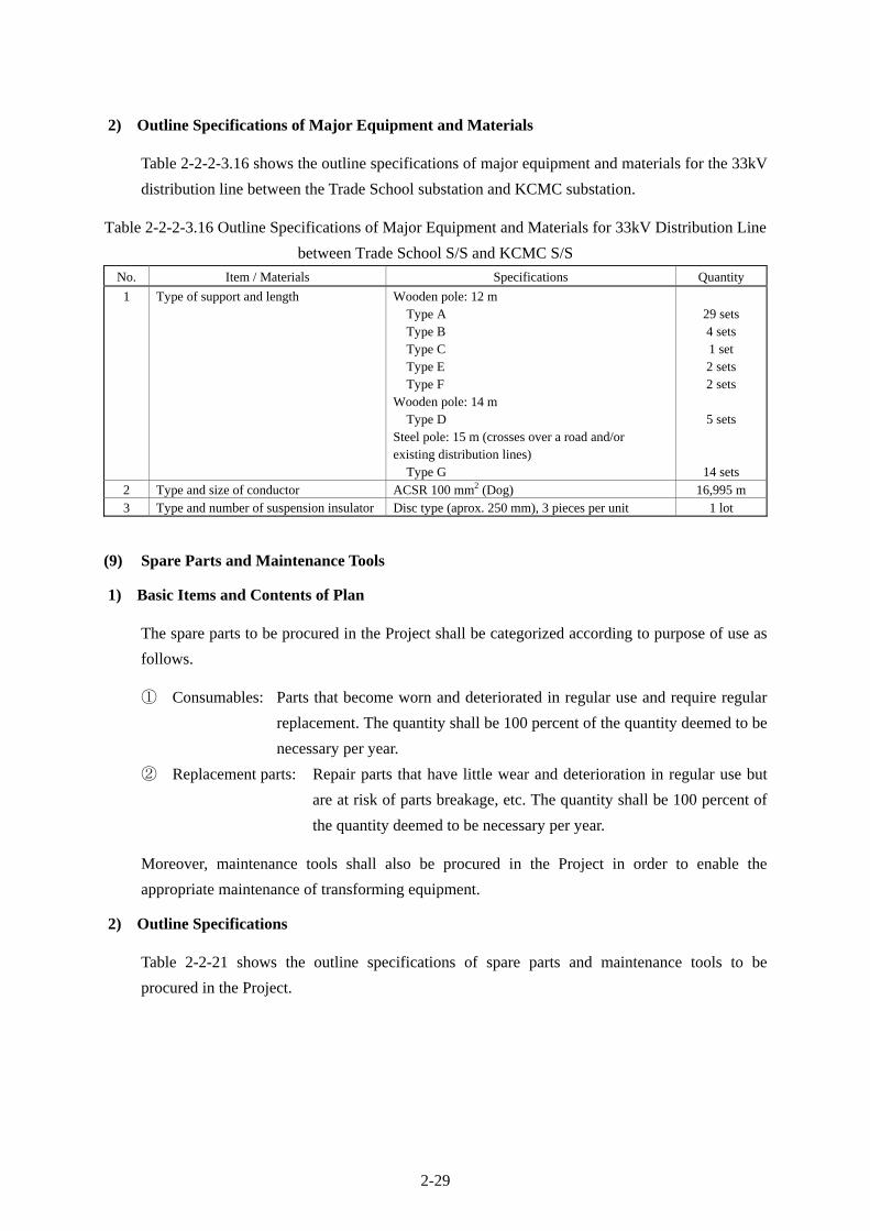
2-29
2) Outline Specifications of Major Equipment and Materials
Table 2-2-2-3.16 shows the outline specifications of major equipment and materials for the 33kV
distribution line between the Trade School substation and KCMC substation.
Table 2-2-2-3.16 Outline Specifications of Major Equipment and Materials for 33kV Distribution Line
between Trade School S/S and KCMC S/S
No. Item / Materials Specifications Quantity
1 Type of support and length Wooden pole: 12 m Type A Type B Type C Type E Type F Wooden pole: 14 m Type D Steel pole: 15 m (crosses over a road and/or existing distribution lines) Type G
29 sets 4 sets 1 set 2 sets 2 sets
5 sets
14 sets 2 Type and size of conductor ACSR 100 mm2 (Dog) 16,995 m 3 Type and number of suspension insulator Disc type (aprox. 250 mm), 3 pieces per unit 1 lot
(9) Spare Parts and Maintenance Tools
1) Basic Items and Contents of Plan
The spare parts to be procured in the Project shall be categorized according to purpose of use as
follows.
① Consumables: Parts that become worn and deteriorated in regular use and require regular
replacement. The quantity shall be 100 percent of the quantity deemed to be
necessary per year.
② Replacement parts: Repair parts that have little wear and deterioration in regular use but
are at risk of parts breakage, etc. The quantity shall be 100 percent of
the quantity deemed to be necessary per year.
Moreover, maintenance tools shall also be procured in the Project in order to enable the
appropriate maintenance of transforming equipment.
2) Outline Specifications
Table 2-2-21 shows the outline specifications of spare parts and maintenance tools to be
procured in the Project.

2-30
2-2-2-3.17 Spare Parts and Maintenance Tools to be Procured in the Project
Name Unit Quantity Remarks
1. Consumable
1.1 Transformer YMCA, Lawate, KCMC, Makuyuni and Kiyungi
substations
(1) Silica gel kg 2 Each substation
2. Replacement parts
2.1 Transformer YMCA, Lawate, KCMC, Makuyuni and Kiyungi
substations
(1) Lamp (each type) pc 1 Each substation
(2) Fuse (each type) pc 1 Each substation
(3) Space heater (each type) pc 1 Each substation
(4) Packing (each type) lot 1 Each substation
2.2 132kV Circuit Breaker Kiyungi substation
(1) Closing coil pc 1
(2) Tripping coil pc 1
(3) Gasket pc 1
2.3 66kV Circuit Breaker Makuyuni and Kiyungi substations
(1) Closing coil pc 1 Each substation
(2) Tripping coil pc 1 Each substation
(3) Gasket pc 1 Each substation
2.4 33kV Switchgear Cubicle YMCA, Lawate, KCMC, Trade School and
Makuyuni substations
(1) Lamp (each type) pc 1 Each substation
(2) Fuse (each type) pc 1 Each substation
(3) Space heater (each type) pc 1 Each substation
2.5 11kV Switchgear Cubicle YMCA, Lawate, and KCMC substations
(1) Lamp (each type) pc 1 Each substation
(2) Fuse (each type) pc 1 Each substation
(3) Space heater (each type) pc 1 Each substation
2.6 132kV Control & Protection Panels Kiyungi substation
(1) Lamp (each type) pc 1
(2) Fuse (each type) pc 1
(3) Space heater (each type) pc 1
2.7 66kV Control & Protection Panels Makuyuni and Kiyungi substations
(1) Lamp (each type) pc 1 Each substation
(2) Fuse (each type) pc 1 Each substation
(3) Space heater (each type) pc 1 Each substation
2.8 33kV Control & Protection Panels Makuyuni substation
(1) Lamp (each type) pc 1

2-31
Name Unit Quantity Remarks
(2) Fuse (each type) pc 1
(3) Space heater (each type) pc 1
2.9 Outdoor Lighting YMCA, Lawate, KCMC and Makuyuni substations
(1) Lamp pc 1 Each substation
(2) Ballast pc 1 Each substation
(3) Photo-cell pc 1 Each substation
(4) Lamp cover pc 1 Each substation
3. Maintenance Tools
3.1 Testing Instruments
(1) DC dielectric tester set 1
(2) Analogue type tester set 1
(3) Phase rotation meter set 1
(4) Voltage detector (High voltage) set 1
(5) Voltage detector (Low voltage) set 1
(6) DC voltage detector set 1
(7) Relay testing kit set 1
(8) Relay maintenance tool set 1
(9) AC power meter set 1
(10) Portable AC volt/amp meter set 1
(11) Portable DC volt/amp meter set 1
(12) WH meter maintenance tool set 1
(13) Insulation resistance tester (Low
voltage)
set 1 500 V class
(14) Insulation resistance tester (High
voltage)
set 1 1,000 V class
(15) Portable earth resistance tester set 1
(16) Digital type multimeter set 1
(17) Clip-on meter set 1
3.2 General Tools
(1) Hydraulic compression tool set 2
(2) Hydraulic termination pliers set 2
(3) Cable cutter set 2
(4) Wire stripper set 2
(5) Portable earthing device set 2
(6) Operation rod for fused cut-out
switch
set 2

2-32
2-2-3 Outline Design Drawing
The outline design drawings for the Project are as indicated below.
Single Line Diagrams
Drawing
No. Drawing Title
AE-01 YMCA S/S Single Line Diagram
BE-01 Lawate S/S Single Line Diagram
DE-01 KCMC S/S Single Line Diagram
EE-01 Trade School S/S Single Line Diagram
FE-01 Makuyuni S/S Single Line Diagram
GE-01 Kiyungi S/S Single Line Diagram
GE-02 Kiyungi S/S Single Line Diagram (Detail)
Layout Plans
Drawing
No. Drawing Title Scale
AL-01 YMCA S/S Layout Plan 1 / 200
BL-01 Lawate S/S Layout Plan 1 / 200
DL-01 KCMC S/S Layout Plan 1 / 200
EL-01 Trade School S/S Layout Plan 1 / 200
FL-01 Makuyuni S/S Layout Plan 1 / 200
FS-01 Makuyuni S/S Layout Plan (Cross Section) 1 / 150
FA-01 Makuyuni S/S Control Building (Floor Plan) 1 / 150
FA-02 Makuyuni S/S Control Building (Elevation) 1 / 150
GL-01 Kiyungi S/S Layout Plan 1 / 500
GS-01 Kiyungi S/S Layout Plan (Cross Section) 1 / 300
GA-01 Kiyungi S/S Control Building (Floor Plan) 1 / 100
GA-02 Kiyungi S/S Control Building (Elevation) 1 / 100
Transmission and Distribution Line Drawings
Drawing No. Drawing Title
HR-01~19 66kV Transmission Line Route Map
HT-01~08 Steel Tower Type
HF-01~03 Steel Tower Foundations
IR-01~03 33kV Distribution Line Route Map
IT-01~08 Assembling Drawing

2-33

2-34

2-35

2-36

2-37
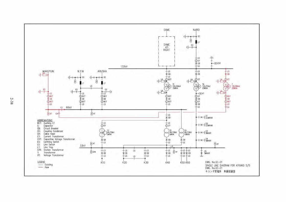
2-38

2-39

2-40

2-41

2-42

2-43

2-44

2-45

2-46

2-47

2-48

2-49

2-50

2-51

2-52

2-53
Swamp

2-54

2-55
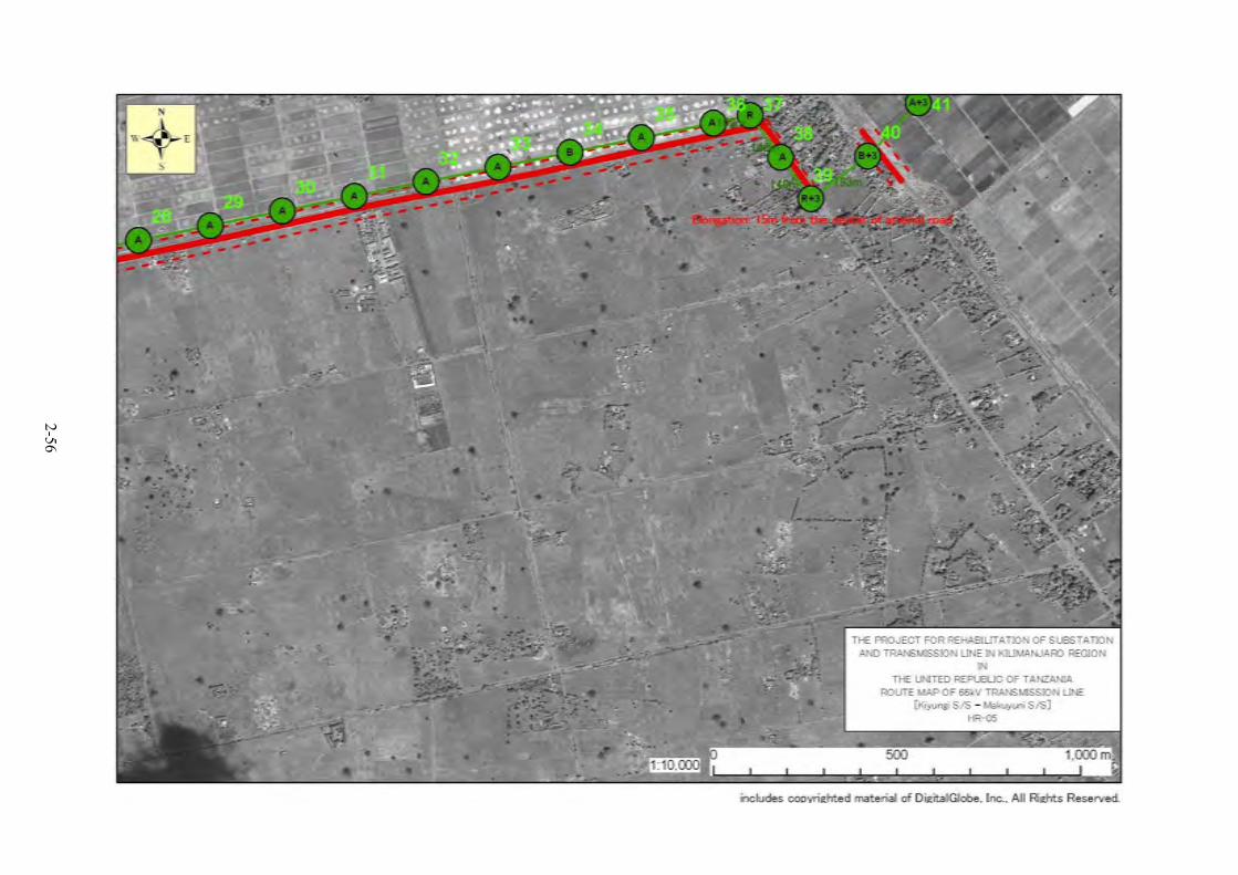
2-56

2-57

2-58

2-59

2-60

2-61

2-62