Embed Size (px)
Citation preview

Shaker Control
User Guide
Rev. 6.3
Application Software Installation Application Software Usage
Terminology Background Theory
LDS-Dactron
Phone (608) 821-6600 Fax. (608) 821- 6691
E-mail: [email protected] Web Site: www.lds-group.com

Information in this document is subject to change without notice. No part of this document may be reproduced or transmitted in any form or by any means, electronic or mechanical, for any purpose, without the express written permission of LDS. LDS makes no warranties on the software, whether express or implied, nor implied warranties of merchantability or fitness for a particular purpose. LDS does not warrant your data, that the software will meet your requirements, or that the operation will be reliable or error free. The user of the software assumes the entire risk of use of the software and the results obtained from use of the software. LDS shall not be liable for any incidental or consequential damages, including loss of data, lost profits, cost of cover or other special or indirect damages. Your rights under law may vary.
US Government Restricted Rights The software and documentation are provided with Restricted Rights. Use, duplication, or disclosure by the Government is subject to restrictions as set forth in subparagraph c(1)(ii) of the Rights in Technical Data and Computer Software clause at DFARS 252.227-7013 or subparagraphs c(1) and (2) of the Commercial Computer Software - Restricted Rights at 48 CFR 52.227-19 as applicable. The Manufacturer is LDS Test and Measurement LLC, 8551 Research Way, M/S 140, Middleton, WI 53562. Copyright ©1997-2008 LDS Test and Measurement. LDS is a member of SPX Corporation. All rights reserved
All trademarks and registered trademarks are the property of their respective holders.
Table of Contents
LDS-Dactron Shaker Control System i
Table of Contents
1 Introduction ............................................................................................................ 1 The Basics ................................................................................................................. 1 This Manual .............................................................................................................. 2 Other Manuals .......................................................................................................... 2 Operating System ..................................................................................................... 2
Application Software ............................................................................................ 3 Application Software Installation ............................................................................. 4
Uninstalling the Software ................................................................................... 10 Run the Shaker Control Software ....................................................................... 10
The first time you run the software ........................................................................ 10 Calibration File ................................................................................................... 10 Help Menu .......................................................................................................... 12
System Information ................................................................................................ 14 About LDS-Dactron Shaker Controller .............................................................. 14 About LDS-Dactron Software Applications ...................................................... 15 About LDS-Dactron Hardware ........................................................................... 16 About Contacting LDS-Dactron ......................................................................... 17
Security Administration .......................................................................................... 17 User Name and Password ................................................................................... 18 First-Time Use .................................................................................................... 18 Changing Your Password ................................................................................... 19 Group Administration ......................................................................................... 19 User Administration ........................................................................................... 21
2 Run a Pre-Defined Project ................................................................................... 22 Starting the program ............................................................................................... 22
From the Desktop ............................................................................................... 22 From the Start Menu ........................................................................................... 22 Program Startup Message ................................................................................... 23
Selecting a Project .................................................................................................. 24 Finding the Project Folder .................................................................................. 24 Finding the Project ............................................................................................. 24
Checking the Project ............................................................................................... 25 Test Setup Items to Check .................................................................................. 26
Running the Project ................................................................................................ 27 The Unit Under Test ........................................................................................... 27 Check the Control Loop ..................................................................................... 27 Check the Power Connections ............................................................................ 28 Before Pressing Start .......................................................................................... 28 Start the Test ....................................................................................................... 28 Monitor the Test ................................................................................................. 28

Table of Contents
LDS-Dactron Shaker Control System ii
Save Data as Required ........................................................................................ 28 End of the Test .................................................................................................... 29
3 File and Project Management ............................................................................. 30 LDS-Dactron Shaker Control System Folder ......................................................... 30 Project Folder Structure .......................................................................................... 31 Creating a New Project ........................................................................................... 32 User Interfaces ........................................................................................................ 33
Simple User Interface (SUI) ............................................................................... 33 Advanced User Interface (AUI) ......................................................................... 34 Differences between SUI and AUI ..................................................................... 35
Open an Existing Project ........................................................................................ 37 Default Project ........................................................................................................ 38 Run Folders ............................................................................................................. 40 Signal Manager ....................................................................................................... 40
Save Signal Manager .......................................................................................... 41 Signal Save Settings (Automatic Data Saving) .................................................. 45 Using More/Less to Enable Signal Saves ........................................................... 49 Recall Signal Manager ....................................................................................... 52 Cache Signal Manager ........................................................................................ 59
Signal Files ............................................................................................................. 63 Signal File Types and Name Conventions ......................................................... 64
Pane Pop-Up Menu ................................................................................................. 70 4 Define a Project ..................................................................................................... 72
Creating a New Project ........................................................................................... 72 Start-Up Page ...................................................................................................... 73 Test Setup Wizard .............................................................................................. 76 Create a New Project .......................................................................................... 80
Setting up a Project: Test & Profile Setup .............................................................. 85 General Test Setup .................................................................................................. 88
Engineering Units ............................................................................................... 89 Shaker Parameters .............................................................................................. 91 Channel Parameters ............................................................................................ 94 Special Signals .................................................................................................. 106 Waterfall Request ............................................................................................. 112 Transmissibility Signals ................................................................................... 113 Chamber Interface Setup .................................................................................. 115 Preferences – Controls & Limit ........................................................................ 123 Preferences – Miscellaneous ............................................................................ 123 Preferences – Email .......................................................................................... 125 Preferences – Abort Action .............................................................................. 127 Preferences – Amplifier Control ...................................................................... 127
Test & Profile Setup – Random & Mixed Mode .................................................. 128 Control Parameters for Random and Mixed-mode .......................................... 129

Table of Contents
LDS-Dactron Shaker Control System iii
Preferences for Random and Mixed-mode ....................................................... 140 Random Profile ................................................................................................. 144 Example Random Profile Setups ...................................................................... 153 Mixed-mode Profiles ........................................................................................ 156 Narrowband Profile for Random on Random (RoR) ....................................... 157 Sine Tones Profile for Sine on Random (SoR) ................................................ 162 Profile for Sine and Random on Random (SRoR) ........................................... 165 Limiting Profile for Random and Mixed-mode ................................................ 166 Schedule for Random ....................................................................................... 168 Example Random Schedule Setups .................................................................. 172 Schedule for Mixed-mode ................................................................................ 174
Test & Profile Setup – Swept Sine, RSTD, & Sine Oscillator ............................. 175 Control Parameters for Sine and RSTD ........................................................... 175 Control Parameters for Resonance Search and Tracked Dwell (RSTD) .......... 183 Control Parameters for Sine Oscillator ............................................................. 183 Preferences for Sine, RSTD, and Sine Oscillator ............................................. 184 Profile for Sine and RSTD ............................................................................... 188 Example Sine Profile Setups ............................................................................ 192 Limiting Profile for Sine .................................................................................. 196 Schedule for Swept Sine ................................................................................... 199 Example Sine Schedule Setups ........................................................................ 206 Schedule for RSTD ........................................................................................... 208 RSTD Dwell Test Using Saved Transmissibility Functions ............................ 214
Test & Profile Setup – Classical Shock, SRS, & TTH ......................................... 218 Control Parameters for Classical Shock, SRS Synthesis, and TTH ................. 218 Control Parameters for TTH ............................................................................. 227 Preferences for Shock, SRS Synthesis, and TTH ............................................. 228 Profile for Classical Shock ............................................................................... 230 Example Classical Shock Profile Setups .......................................................... 237 Profile for SRS Synthesis ................................................................................. 240 Example SRS Synthesis Profile Setup ............................................................. 248 Profile for Transient Time History (TTH) ........................................................ 251 Example TTH Profile Setups ............................................................................ 261 Schedule for Shock, SRS Synthesis, and TTH ................................................. 262 Example Shock Schedule Setups ...................................................................... 266
Test & Profile Setup – Long Time History (LTH) ............................................... 267 Control Parameters for LTH ............................................................................. 268 Preferences for LTH ......................................................................................... 273 LTH Profile ...................................................................................................... 275 Waveform Profile for LTH ............................................................................... 280 Waveform Editor ............................................................................................. 281 Examples of LTH Profile Compensation ......................................................... 296 LTH Profile and Schedule ................................................................................ 301
Table of Contents
LDS-Dactron Shaker Control System iv
Profile Block Diagram .......................................................................................... 309 Edit Controls for the Block Diagram ................................................................ 310
Project Sequence ................................................................................................... 311 Digital Input and Output ....................................................................................... 313
Digital Input Pin Assignment ........................................................................... 313 Default Digital Output Signals ......................................................................... 315 Programming the Digital Input Signals ............................................................ 316 Troubleshooting Tools ...................................................................................... 322
5 Run a Project ...................................................................................................... 324 Control Panel .................................................................................................... 324
Overview of the Run Process ............................................................................... 325 Run Steps and Modes ....................................................................................... 325 The Start Request ............................................................................................. 327
Global Test and Control Menus ............................................................................ 329 Test Menu Commands ...................................................................................... 330 Preview Test ..................................................................................................... 332
Random and Mixed-mode Run Controls .............................................................. 332 Common Controls for Random and Mixed-mode ............................................ 333 Run Controls for Mixed-mode ......................................................................... 335
Swept Sine, RSTD, & Sine Oscillator Run Controls ........................................... 336 Run Controls for Sine and RSTD ..................................................................... 336 Run Controls for Sine Oscillator ...................................................................... 336 Common Controls for Sine, RSTD, and Sine Oscillator .................................. 337 Run Controls for RSTD .................................................................................... 342
Classical Shock, SRS Synthesis, and TTH Run Controls .................................... 345 Common Controls for Shock, SRS Synthesis, and TTH .................................. 345 Pre-Test Drive Pause for TTH .......................................................................... 347
Long Time History Run Controls ......................................................................... 348 Common Controls for LTH .............................................................................. 348 Special On-Line Displays for LTH .................................................................. 350
Summary of F Key Commands ............................................................................ 350 Random and Mixed-mode ................................................................................ 351 Swept Sine and RSTD ...................................................................................... 351 Classical Shock, SRS Synthesis, and TTH ....................................................... 351 Long Time History ........................................................................................... 351
Special On-Line Displays ..................................................................................... 352 Channel Status Window ................................................................................... 352 Run Log Window ............................................................................................. 353 Parameter Summary Window ........................................................................... 354 Numeric Display ............................................................................................... 355 Chamber Watch Window ................................................................................. 355
Project Sequence Control and Monitoring ........................................................... 356 Project Sequence Start ...................................................................................... 356

Table of Contents
LDS-Dactron Shaker Control System v
Project Sequence Monitoring ........................................................................... 357 Project Sequence Log ....................................................................................... 358
6 Create Screens and Reports ............................................................................... 359 What is a Pane ...................................................................................................... 360
Standard Windows ............................................................................................ 360 Composite Window .......................................................................................... 360 Profile Block Diagram Window ....................................................................... 361 The Customized Window ................................................................................. 362
Window Menu ...................................................................................................... 362 One-Pane Window ............................................................................................ 362 2D Displays ...................................................................................................... 363 3D Displays ...................................................................................................... 365 Cascade and Tile ............................................................................................... 365 Tool Bar, Status Bar, and Control Panel .......................................................... 365 Active Window Selection ................................................................................. 366 Parameter Summary Window ........................................................................... 366 Numeric Display ............................................................................................... 367 Channel Status Window ................................................................................... 370 Run Log Window ............................................................................................. 373 Chamber Watch Window ................................................................................. 373 Project Sequence Window ................................................................................ 373 Digital Input Monitor ....................................................................................... 374
Pane Menu ............................................................................................................ 375 Making a Pane the Active Pane ........................................................................ 375 Moving the Pane Borders ................................................................................. 375 Contents of the Pane ......................................................................................... 376 Pane Default Parameters ................................................................................... 386 Add and Delete Cursor Mark ........................................................................... 387 Add and Delete Annotation .............................................................................. 387 Zoom In and Zoom Out .................................................................................... 387 Auto. Fit Y-Axis ............................................................................................... 388
Pane Pop-Up Menu ............................................................................................... 388 Cursor Menu ......................................................................................................... 390
Add and Delete Normal Cursor ........................................................................ 392 Add and Delete Normal Y Cursor .................................................................... 393 Sideband Cursors .............................................................................................. 393 Add and Delete Peak Cursors ........................................................................... 393 Add and Delete Valley Cursors ........................................................................ 393 Add and Delete Harmonic Cursors ................................................................... 393 Calculate Q Factor with Normal Cursor ........................................................... 394 Find Nearest Peak or Valley ............................................................................. 394 Cursor Global Setup ......................................................................................... 394
Report Functions ................................................................................................... 398

Table of Contents
LDS-Dactron Shaker Control System vi
All Reports Are Generated Through MS-Word® ............................................ 398 Difference between a Pane and Screen Bitmap ................................................ 400 Run-time Status Attached to the Plot ............................................................... 400 For MS-Word 2007 Users ................................................................................ 401 For MS-Word 2003 Users ................................................................................ 404 Use the MS-Word Template ............................................................................. 407 Generate a Color Plot for the Pane ................................................................... 409 Print Multiple Plots per Page ............................................................................ 410 Save Test Results .............................................................................................. 412
Report Menu ......................................................................................................... 414 Current Pane ..................................................................................................... 415 Test ID to Customize and Add Test Information ............................................. 415 Project Report ................................................................................................... 418 Report Setup ..................................................................................................... 419 Template Setup ................................................................................................. 424 Template Report ............................................................................................... 427 Output Saved Results to MS-Word .................................................................. 428 Parameter Summary Window ........................................................................... 430
7 Tool Bar and Mouse Controls ........................................................................... 432 Project Tool Bar .................................................................................................... 432 New Project Tool Bar Buttons .............................................................................. 433 Global Tool Bar Buttons ....................................................................................... 434 Random and Mixed-Mode Special Buttons .......................................................... 437 Sine and RSTD Special Buttons ........................................................................... 438 Shock, SRS Synthesis, and TTH Special Buttons ................................................ 439 LTH Special Buttons ............................................................................................ 440 Waveform Editor Special Buttons ........................................................................ 440 Test Setup Icons .................................................................................................... 442 View Menu ........................................................................................................... 442 Mouse Controls ..................................................................................................... 446
Working with Windows and Panes .................................................................. 446 Changing Y and X Scales ................................................................................. 446 Zoom In ............................................................................................................ 448 Cursor Movement ............................................................................................. 450 Moving the Cursor Readout ............................................................................. 451 Cursor Readout for RMS and Power ................................................................ 452 Adding Cursor Marks ....................................................................................... 452 Peak and Valley Cursors .................................................................................. 453 Quality Factor “Q” and Damping Factor Readout ........................................... 454 Harmonic Cursor .............................................................................................. 455 Adding Annotation and Annotation Box Movement ....................................... 458 Setting Y and X Unit Labels and the Plot Title ................................................ 460 Window Pane Border Movement ..................................................................... 461

Table of Contents
LDS-Dactron Shaker Control System vii
Accessing the Pane Contents Dialog Box ........................................................ 462 Working with the Profile Block Diagram ............................................................. 462
8 Special Displays and Functions ......................................................................... 464 Waterfall Displays ................................................................................................ 464
How to Set Up a Waterfall Display .................................................................. 464 Creating Waterfall Displays ............................................................................. 469 Waterfall Cursor ............................................................................................... 475
Signal Viewer Utility ............................................................................................ 476 PC Camera ............................................................................................................ 478
9 ActiveX Signal Reader ....................................................................................... 480 ActiveX Signal Reader Methods .......................................................................... 480
LoadSignal ........................................................................................................ 480 GetData ............................................................................................................. 481 GetSliceValueArray ......................................................................................... 482 GetEventInform ................................................................................................ 482
ActiveX Signal Reader Properties ........................................................................ 483 ActiveX Signal Reader Enumerations .................................................................. 486
Enum DATAFORMAT .................................................................................... 486 Eunm TRANSUNITS ....................................................................................... 486 Enum WNDTYPE ............................................................................................ 487 Enum WEIGHTING ......................................................................................... 487
Adding ActiveX Signal Reader to a Project ......................................................... 488 Visual C++ ....................................................................................................... 488 Visual Basic ...................................................................................................... 495
10 Shaker Vibration Control Theory ..................................................................... 497 Overview .............................................................................................................. 497 Single Degree-of-Freedom System ...................................................................... 498 Random Vibration Control ................................................................................... 499
Random Control Process .................................................................................. 499 Safety Checks ................................................................................................... 502
Mixed-mode Control ............................................................................................ 502 Swept Sine Vibration Control............................................................................... 505
Sine Control Process ......................................................................................... 507 Real-time Tracking Filter with Adaptive Bandwidth ....................................... 508 RMS, Mean, and Peak Detection ..................................................................... 510
Resonant Search, Dwell and Track (RSTD) ......................................................... 511 RSTD Requires Transmissibility Measurement ............................................... 511 Frequency-Locked Dwell ................................................................................. 514 Resonance-Tracked Dwell ................................................................................ 514
Classical Shock Control ........................................................................................ 516 Waveform Compensation ................................................................................. 517 Shock Control Process ...................................................................................... 519
Shock Response Spectrum (SRS) Synthesis ........................................................ 520

Table of Contents
LDS-Dactron Shaker Control System viii
Basics of SRS Synthesis ................................................................................... 520 Limiting Control with Automatic Drive Notching ............................................... 526 Long Time History Replication ............................................................................ 527
Real-time LTH Time Domain Control ............................................................. 527 LTH Control Algorithm ................................................................................... 528 Using LTH Time Domain Control ................................................................... 531
References ............................................................................................................ 532 11 Glossary ............................................................................................................... 533
Abort Rate ........................................................................................................ 533 Abort Sensitivity ............................................................................................... 533 Abort Tolerances .............................................................................................. 533 Acceleration ...................................................................................................... 534 Accelerometer ................................................................................................... 534 Alarm Tolerances ............................................................................................. 534 Amplitude ......................................................................................................... 534 Anti-Aliasing Filter .......................................................................................... 534 Anti-Resonance ................................................................................................ 534 Auto-correlation Function ................................................................................ 535 Averaging ......................................................................................................... 535 Averaging Number ........................................................................................... 536 Bandpass Filter ................................................................................................. 536 Bandwidth ......................................................................................................... 536 Bandwidth, Fixed ............................................................................................. 537 Bandwidth, Proportional ................................................................................... 537 Broadband Random Vibration .......................................................................... 538 Channel Status .................................................................................................. 538 Compensation, Shock Waveform ..................................................................... 538 Composite ......................................................................................................... 538 Compression Rate ............................................................................................. 538 Control .............................................................................................................. 539 Control Dynamic Range ................................................................................... 539 Control Loop .................................................................................................... 539 Control Signal ................................................................................................... 539 Control Strategy ................................................................................................ 540 Correlation Function ......................................................................................... 540 Crest Factor ...................................................................................................... 540 Critical Damping .............................................................................................. 540 Damping ........................................................................................................... 541 Decibel (dB) ..................................................................................................... 541 Degrees of Freedom (DOF) .............................................................................. 541 Demand Profile ................................................................................................. 542 Deterministic Signals ........................................................................................ 542 Displacement .................................................................................................... 542

Table of Contents
LDS-Dactron Shaker Control System ix
Distortion .......................................................................................................... 542 Drive ................................................................................................................. 542 Drive Limit ....................................................................................................... 542 Duration of Shock Pulse ................................................................................... 542 Dynamic Range ................................................................................................ 543 Dwell ................................................................................................................ 543 Equalization ...................................................................................................... 543 Fourier Transform ............................................................................................ 543 FFT ................................................................................................................... 544 Fraction of Critical Damping ............................................................................ 544 Frequency ......................................................................................................... 545 G ....................................................................................................................... 545 H (signal) ......................................................................................................... 545 H inverse (Hinv signal) .................................................................................... 545 Harmonic .......................................................................................................... 545 High-pass filter ................................................................................................. 545 Level ................................................................................................................. 545 Level Event ....................................................................................................... 546 Lines (frequency or spectral) ............................................................................ 546 Line Abort Ratio ............................................................................................... 546 Linear System ................................................................................................... 546 Linear Change Rate .......................................................................................... 546 Logarithmic Change Rate ................................................................................. 546 Loop Time ........................................................................................................ 546 Low-Pass Filter ................................................................................................. 547 Maximum Frequency ........................................................................................ 547 Monitor Channel ............................................................................................... 547 Narrowband Random Vibration ....................................................................... 547 Narrowband Sine Vibration .............................................................................. 547 Natural Frequency ............................................................................................ 547 Node ................................................................................................................. 548 Noise ................................................................................................................. 548 Pane .................................................................................................................. 548 Peak-to-Peak Value .......................................................................................... 548 Zero-to-Peak Value .......................................................................................... 548 Power Spectral Density (PSD) ......................................................................... 548 Pre-Test ............................................................................................................. 549 Project ............................................................................................................... 549 Profile and Schedule ......................................................................................... 550 Q (quality factor) .............................................................................................. 550 Ramp-up rate .................................................................................................... 550 Random Vibration ............................................................................................ 550 Resonance Dwell .............................................................................................. 551
Table of Contents
LDS-Dactron Shaker Control System x
Safety Check ..................................................................................................... 551 RMS (Root Mean Square) ................................................................................ 551 RMS check ....................................................................................................... 551 Schedule ........................................................................................................... 552 Shock Response Spectrum (SRS) ..................................................................... 552 Sigma Clipping ................................................................................................. 552 Spectrum ........................................................................................................... 553 Sweep Cycle ..................................................................................................... 553 Sweep Direction ............................................................................................... 553 Sweep Event ..................................................................................................... 553 Sweep Rate ....................................................................................................... 553 Sweep Type ...................................................................................................... 553 Tracking Filter .................................................................................................. 554 Transmissibility ................................................................................................ 554 Variance ............................................................................................................ 554 Waterfall Plot .................................................................................................... 554 Waterfall Plus Slice Window ........................................................................... 554 White Noise ...................................................................................................... 555
12 License Agreement ............................................................................................. 556 13 Manual Revision History ................................................................................... 557

Introduction
LDS-Dactron Shaker Control System 1
1 Introduction
The Basics The purpose of Environmental vibration testing is to ensure that a specific Unit Under Test (UUT) can perform its desired function when subjected to the vibration stress of its operating environment. A Shaker System allows you, the operator, to verify this in a controlled environment. The emphasis here is on a controlled environment.
A complete Shaker System consists of seven major components:
UUT – The Unit Under Test is the essential component of the system.
Fixture – The Fixture is the device that holds the UUT and simulates its normal mounting environment.
Head – The Head of the shaker is the part to which the fixture is attached.
Shaker – The Shaker converts the electronic signal that describes the desired test into vibratory motion.
Amplifier – The Amplifier multiplies the electronic signal produced by the control system. The purpose is to achieve an amplitude sufficient to “drive” the shaker at the proper levels.
Control System – The Control System compensates for the dynamics of the shaker and UUT and creates an electronic signal that causes the desired vibratory motion.
Sensors – The Sensors measure the vibratory motion and convert this motion into an electronic signal that can be measured by the control system.
The above list is missing two essential items. The missing items are you and the Test Definition. It is your responsibility to set up a test to match the desired Test Definition. In setting up the test, you should keep the capabilities of your Shaker System in mind. You should also ensure the safety of the UUT and Shaker System. To achieve these ends, you should understand all the functions and controls of the Control System.

Introduction
LDS-Dactron Shaker Control System 2
This Manual This manual explains all the controls and functions of the LDS-Dactron Shaker Control System. Any person responsible for operating or maintaining the Shaker Control System should be fully familiar with the contents of this manual. Operators whose task it is simply to run, but not define tests, need only be familiar with Section 2, “Run a Pre-Defined Project”.
The Introduction of this manual covers the installation of hardware and software modules for the LDS-Dactron Shaker Control System, the method for determining key System Information such hardware serial numbers and software version numbers, and the method for setting up security protection for your system.
Other sections of this manual cover:
• Defining a Test
• Running a Test
• Menus
• Tools
• Dialogs
• Background Theory
The final section is a glossary of useful terms and definitions for vibration control and shaker systems.
Other Manuals The operator of this system should be familiar with the operation manuals of the other components of the entire Shaker System. These manuals should be readily available during test definition sessions.
Operating System The LDS-Dactron Shaker Control System operates in the Microsoft Windows® environment. This manual will not explain normal Windows

Introduction
LDS-Dactron Shaker Control System 3
functions. At a minimum, you should be familiar with the following operations used in a Windows environment:
Point Maximize Close
Click Minimize Scroll
Click and Drag Iconize Select
Highlight Open Expand
Application Software The software user interface is compliant withWindows 2000® and Windows XP® standards for menus and operations.
The following applications software is available:
• Random Vibration Control
• Random on Random (RoR) Vibration Control
• Sine on Random (SoR) Vibration Control
• Sine and Random on Random (SRoR) Vibration Control
• Swept Sine Vibration Control
• Resonance Search, Dwell and Track (RSTD) Vibration Control
• Sine Oscillator Control
• Classical Shock Transient Control
• Shock Response Spectrum (SRS) Transient Control
• Time Transient History (TTH) Control
• Long Time History (LTH) Control
Introduction
LDS-Dactron Shaker Control System 4
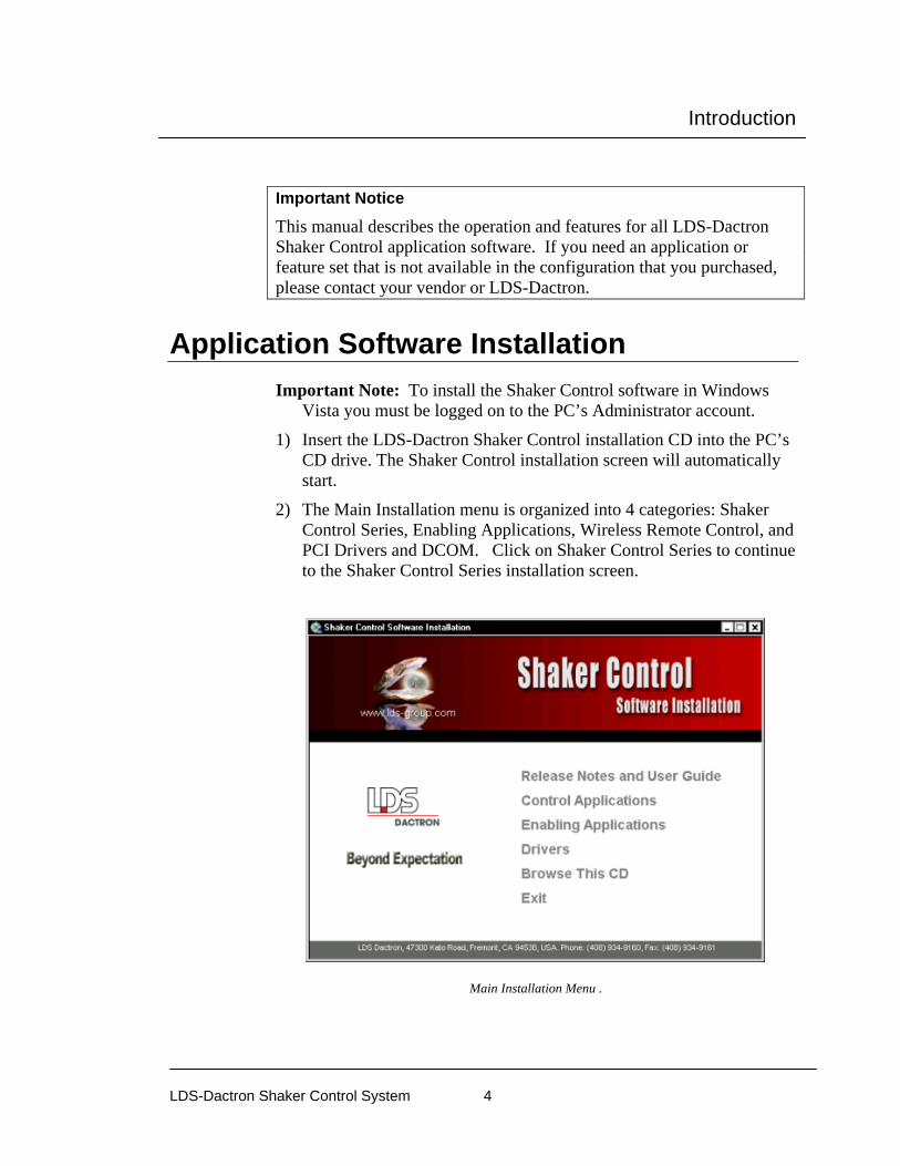
Important Notice This manual describes the operation and features for all LDS-Dactron Shaker Control application software. If you need an application or feature set that is not available in the configuration that you purchased, please contact your vendor or LDS-Dactron.
Application Software Installation Important Note: To install the Shaker Control software in Windows
Vista you must be logged on to the PC’s Administrator account.
1) Insert the LDS-Dactron Shaker Control installation CD into the PC’s CD drive. The Shaker Control installation screen will automatically start.
2) The Main Installation menu is organized into 4 categories: Shaker Control Series, Enabling Applications, Wireless Remote Control, and PCI Drivers and DCOM. Click on Shaker Control Series to continue to the Shaker Control Series installation screen.
Main Installation Menu .

Introduction
LDS-Dactron Shaker Control System 5
3) The Control Applications installation menu includes: Shaker Control (Control Applications, Analyze Anywhere, and system controller), Demo Project Files, and Calibration. Click on Control Application V6.X to install the Shaker Control Application software.
Shaker Control Series Menu
4) Windows will load the Install Shield Wizard to guide you through the installation.
5) Read the software License Agreement and decide whether or not you want to accept the license terms, and then click Next.
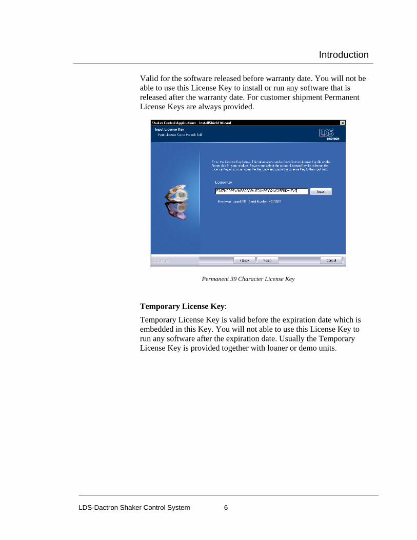
6) In the Input License Key screen, you will be prompted to enter the License Key. Refer to the License Key file on the CD included with your system. You can either import the file using the Import button or you can open the file then copy and paste it into the License Key input field. Please store this information in a safe place where it can be easily retrieved.
The new License Key is setup so that there are two general types: Permanent and Temporary. Below are the explanations of these two new License Key types:
Permanent License Key:
Introduction
LDS-Dactron Shaker Control System 6
Valid for the software released before warranty date. You will not be able to use this License Key to install or run any software that is released after the warranty date. For customer shipment Permanent License Keys are always provided.
Permanent 39 Character License Key
Temporary License Key:
Temporary License Key is valid before the expiration date which is embedded in this Key. You will not able to use this License Key to run any software after the expiration date. Usually the Temporary License Key is provided together with loaner or demo units.

Introduction
LDS-Dactron Shaker Control System 7
Temporary 39 Character License Key
Invalid License Key: Message will be shown when the License Key is invalid. The License Key may be for another software (i.e. Calibration), or may be for another hardware platform. Please confirm that you enter or import the correct License Key.
Invalid 39 Character License Key

Introduction
LDS-Dactron Shaker Control System 8
7) It is recommended to accept the default installation location.
8) Next select a folder to put the program icon in. After the software is
installed you can find the LDS-Dactron folder on the desktop.
9) In the Select Options screen, you can select the following options: Desktop Shortcut, Default Units, and File Extension Association. Desktop Shortcut allows the user to specify the location to install the application software’s desktop shortcut, either on the desktop or in

Introduction
LDS-Dactron Shaker Control System 9
the LDS-Dactron folder on the desktop. Default Units allows the user to pre-set the default Engineering Units to use for a default project in the application software. You can also choose to associate the application software with the project file extension. This feature allows you to double click on the project icon to start the application and load the project file. If you have the Thermal Chamber Interface option you can select the type of chamber that you are using.
10) The Check Setup Information screen allows the user to confirm installation settings are correct. If they are not correct, the user can review or change settings by clicking the Back button. Otherwise, click on Next to proceed with the installation.

Introduction
LDS-Dactron Shaker Control System 10
11) Click on Finish to complete the installation.
Uninstalling the Software The LDS-Dactron software can be uninstalled from the computer by using the standard Windows Add/Remove Software Control Panel.
Run the Shaker Control Software Double click on the desktop icon or on the icon located in the LDS-Dactron folder on the desktop. Please read the next section before running the system for the first time.
The first time you run the software
Calibration File The first time you run Shaker Control, you will be prompted for the Calibration File.

Introduction
LDS-Dactron Shaker Control System 11
Calibration File
Your Shaker Control unit is calibrated prior to shipment. Each unit is shipped with a calibration file that must be installed onto the local PC. The calibration file has the following nomenclature shown here where xxxxxxx is the serial number of the Shaker Control unit:
Cal_xxxxxxx.dat
Note: This serial number can be found in the About Box listing under the Help menu.
If the calibration file does not already exist in your \bin\ directory, the application software will prompt you to import a calibration file.
If you click “Yes”, the following dialog box will appear. This will allow you to upload the calibration file from the CD supplied with the unit. This disk is labeled “Calibration File for S/N xxxxxxxx.”
Importing a Calibration File
Introduction
LDS-Dactron Shaker Control System 12
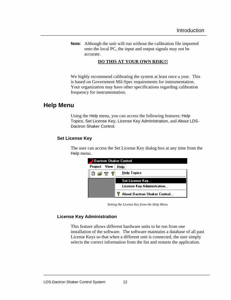
Note: Although the unit will run without the calibration file imported onto the local PC, the input and output signals may not be accurate.
DO THIS AT YOUR OWN RISK!!!
We highly recommend calibrating the system at least once a year. This is based on Government Mil-Spec requirements for instrumentation. Your organization may have other specifications regarding calibration frequency for instrumentation.
Help Menu Using the Help menu, you can access the following features: Help Topics, Set License Key, License Key Administration, and About LDS-Dactron Shaker Control.
Set License Key
The user can access the Set License Key dialog box at any time from the Help menu.
Setting the License Key from the Help Menu
License Key Administration
This feature allows different hardware units to be run from one installation of the software. The software maintains a database of all past License Keys so that when a different unit is connected, the user simply selects the correct information from the list and restarts the application.

Introduction
LDS-Dactron Shaker Control System 13
Set As Default sets the highlighted unit as the default. To change the codes to a different unit, highlight the line with the unit serial number and click Set As Default. Click on OK then quit and restart the software.
Remove removes the serial number and codes from the database.

Introduction
LDS-Dactron Shaker Control System 14
System Information The System configuration is displayed from the About LDS-Dactron Shaker Controller selection under the Help menu or from the Help icon located on the icon bar.
This information is vital to have when you contact LDS-Dactron’s Technical Support to resolve potential problems. There are four pages in About. The pages are accessible via their respective “index” tabs.
About LDS-Dactron Shaker Controller The first tab (About) in the About LDS-Dactron Shaker Controller window shows the software version, and available PC memory and free hard disk space as shown below:
Installed Software Version Number
Introduction
LDS-Dactron Shaker Control System 15
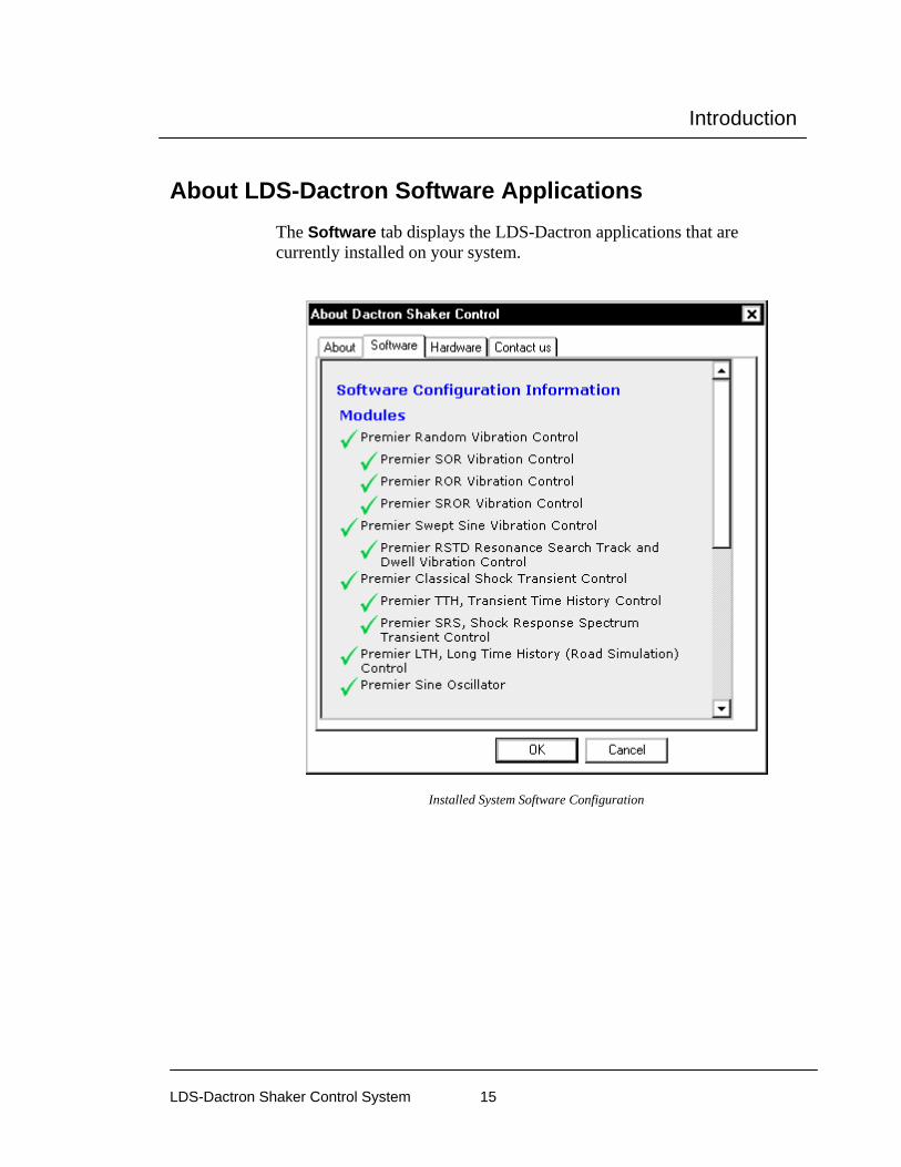
About LDS-Dactron Software Applications The Software tab displays the LDS-Dactron applications that are currently installed on your system.
Installed System Software Configuration
Introduction
LDS-Dactron Shaker Control System 16
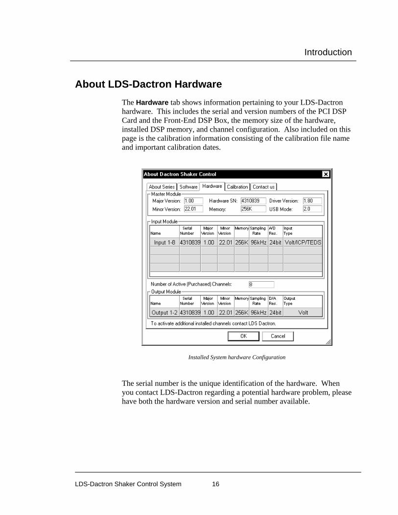
About LDS-Dactron Hardware The Hardware tab shows information pertaining to your LDS-Dactron hardware. This includes the serial and version numbers of the PCI DSP Card and the Front-End DSP Box, the memory size of the hardware, installed DSP memory, and channel configuration. Also included on this page is the calibration information consisting of the calibration file name and important calibration dates.
Installed System hardware Configuration
The serial number is the unique identification of the hardware. When you contact LDS-Dactron regarding a potential hardware problem, please have both the hardware version and serial number available.

Introduction
LDS-Dactron Shaker Control System 17
About Contacting LDS-Dactron The Contact Us page shows contact information for LDS-Dactron. It includes our shipping address, telephone and fax number, and Email addresses.
Contacting LDS-Dactron
Security Administration Security Administration is an optional software feature that allows you to protect your LDS-Dactron Shaker Control from unauthorized use. The privilege to access various groups of functions can be defined by the administrator or the person who has the Security Administration privilege.
If you do not have the Security Option or do not configure this feature, anyone using the PC has full access to the system.

Introduction
LDS-Dactron Shaker Control System 18
The following key words are used in the security administration portion of the software:
• User Name
• Password
• Group Administration
• User Administration
User Name and Password If the security software option is installed, each time when you start the application, the operator will be prompted to enter a User Name and Password to gain access to the System.
System Access Checks for User name and Password
Enter a User name and Password to identify yourself. Note: the User name and Password are NOT case sensitive. Then Click OK to access to the System.
First-Time Use The first time the system is used the default User name and the default Password are both blank. Privilege is set to the highest level - Administrator. We recommend that you set the User name, Password, and privilege level during this first session.

Introduction
LDS-Dactron Shaker Control System 19
Changing Your Password To change the password, click Change Password under the Help menu. The actual password is protected and will not appear in plain text anywhere in the system. The Group Administrator has the ability to change a password, and its level of access to the system.
Using the Help menu to change the Password
Selecting Change Password from the Help menu will invoke the Change Password dialog.
Entry of a New Password
Group Administration Only the Administrator has access to this function. Select Security Administration /Group Administration from Help to set privileges for each user.

Introduction
LDS-Dactron Shaker Control System 20
Using the Group Administration Dialog to Set User Privileges
Then you can add or delete a group and assign the right to access various functions to this group. In the example shown above, a new group Technician has just been added. There can be many different levels of access. It is possible to create an “Analysis” Group, which has access only to the Reporting Function.
The last column in the dialog grants the right of Security Administration. Any group with this privilege has the ability to again access to all the functionality of Group Administration and User Administration.
The Lock Project Files enables write protection for project files. Locked files can be read and used, or modified and used. However, a modified file cannot be saved unless it is first unlocked or if it is saved under a different name. This security feature protects against changes to the original parameter setting of the locked project. It is used in conjunction with the Lock and Unlock project files commands within each application. These commands are found under the Project menu in each application.

Introduction
LDS-Dactron Shaker Control System 21
The group Administrator cannot be deleted, nor can it be modified to reduce the ability to administer security access to the system.
User Administration To access this function, select Security Administration/User Administration under the Help menu. This dialog allows you add or delete users.
User Administration Dialog

Run a Pre-Defined Project
LDS-Dactron Shaker Control System 22
2 Run a Pre-Defined Project The following section will assist you in running a Project that has been pre-defined. It offers a step-by-step description of the actions involved in running this type of project. If you need additional information at any time while running the project, the online Help Topics points you to the relevant section of this manual or to other resource material.
Starting the program The images in this manual are sample screens; your computer screens may vary and contain different arrangements and ancillary programs.
From the Desktop From the Windows Desktop, find the LDS-Dactron Shaker Control Icon. This icon can be easily identified by the LDS-Dactron Logo. Double-click on the LDS-Dactron icon.
LDS-Dactron Shaker Control Icon
From the Start Menu If you have not created a Desktop shortcut to the LDS-Dactron Shaker Control software, you may also start Shaker Control from the Start/Programs Menu under the LDS-Dactron folder (unless specified differently during the software installation).
Run a Pre-Defined Project
LDS-Dactron Shaker Control System 23
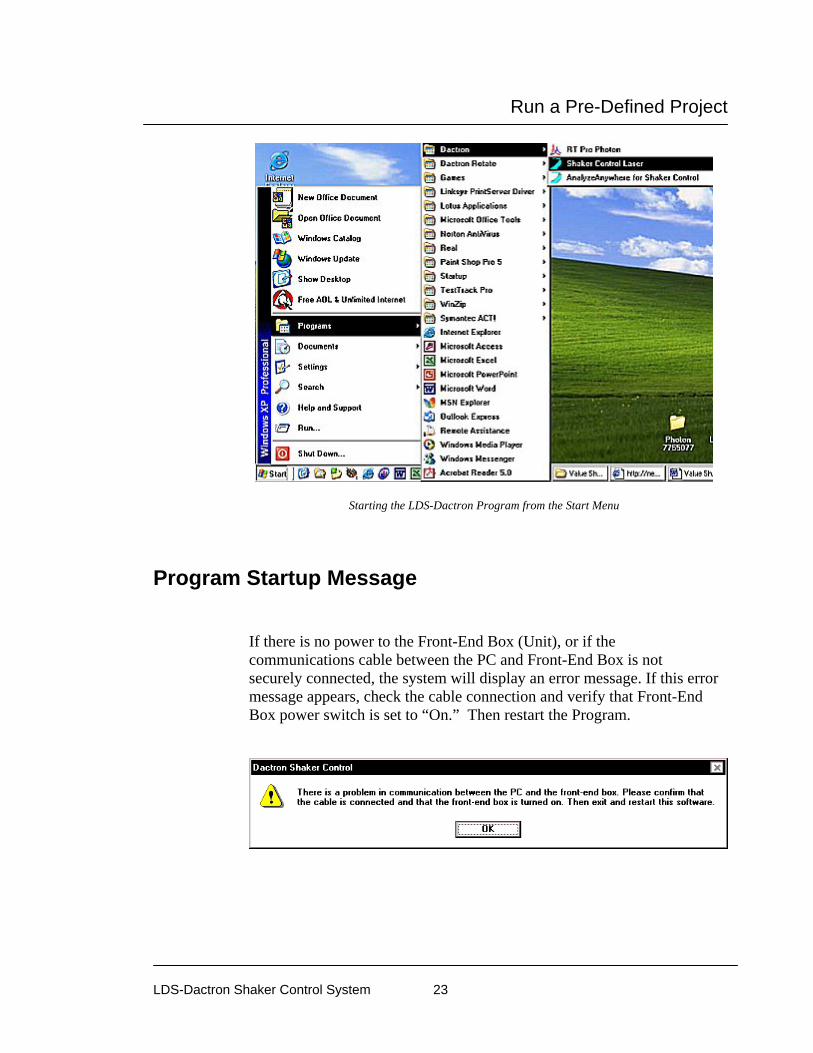
Starting the LDS-Dactron Program from the Start Menu
Program Startup Message
If there is no power to the Front-End Box (Unit), or if the communications cable between the PC and Front-End Box is not securely connected, the system will display an error message. If this error message appears, check the cable connection and verify that Front-End Box power switch is set to “On.” Then restart the Program.
Run a Pre-Defined Project
LDS-Dactron Shaker Control System 24
Selecting a Project You may now open a Project, using either the Project menu or the Tool Bar icon.
Hint – see Section 7, “Tool Bar and Mouse Controls.”
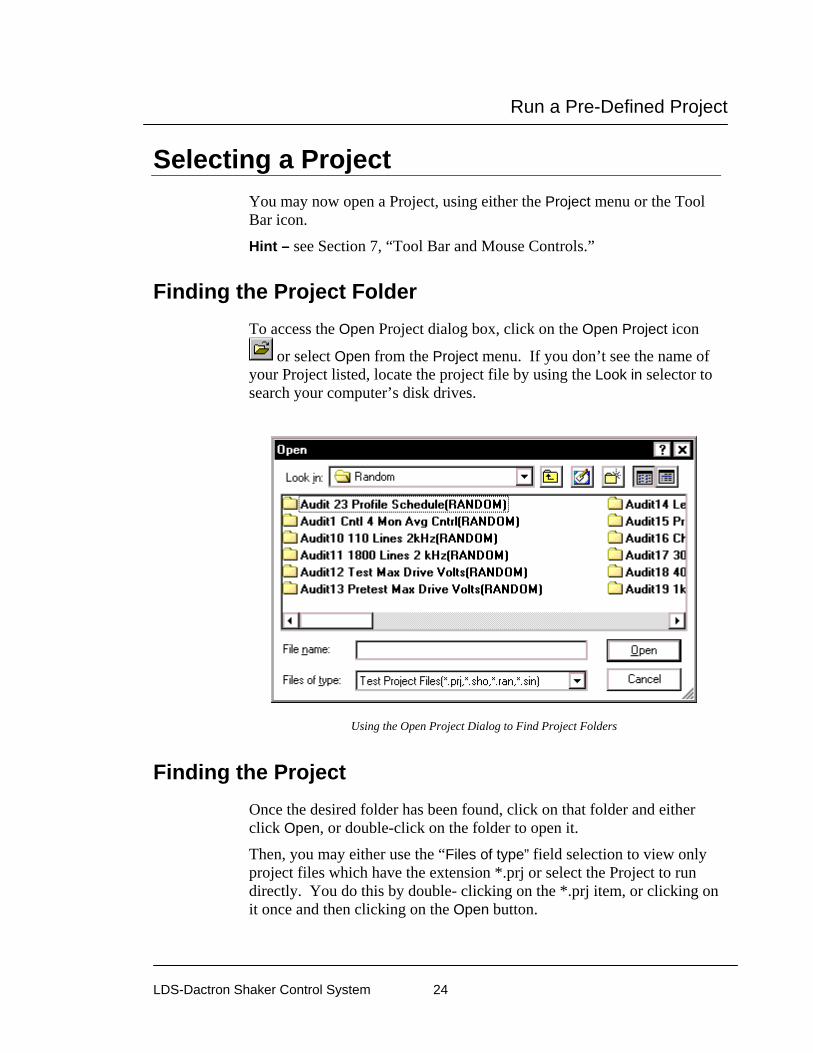
Finding the Project Folder To access the Open Project dialog box, click on the Open Project icon
or select Open from the Project menu. If you don’t see the name of your Project listed, locate the project file by using the Look in selector to search your computer’s disk drives.
Using the Open Project Dialog to Find Project Folders
Finding the Project Once the desired folder has been found, click on that folder and either click Open, or double-click on the folder to open it.
Then, you may either use the “Files of type” field selection to view only project files which have the extension *.prj or select the Project to run directly. You do this by double- clicking on the *.prj item, or clicking on it once and then clicking on the Open button.

Run a Pre-Defined Project
LDS-Dactron Shaker Control System 25
Project File within a Project Folder
After these steps, the project will be open.
Hint – see Section 3, “Project and File Management.”
Checking the Project
All the Test Setup dialog pages should be checked against the written records for your project to ensure that all values are intact and valid. This ensures that no values in the original Project have been inadvertently changed. This step prevents the use of setup parameters that may not be valid for your test (even though the LDS-Dactron Shaker Control System will accept them). Select the menu items one at a time, and verify the data. Click Cancel on each page after the check is complete. Notify a supervisor if any discrepancies exist. If discrepancies exist, DO NOT PROCEED FURTHER.
Run a Pre-Defined Project
LDS-Dactron Shaker Control System 26
Test Setup Items to Check
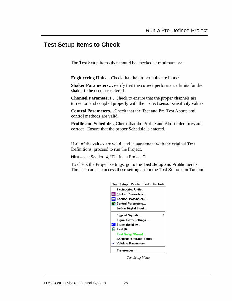
The Test Setup items that should be checked at minimum are:
Engineering Units…Check that the proper units are in use
Shaker Parameters…Verify that the correct performance limits for the shaker to be used are entered
Channel Parameters…Check to ensure that the proper channels are turned on and coupled properly with the correct sensor sensitivity values.
Control Parameters…Check that the Test and Pre-Test Aborts and control methods are valid.
Profile and Schedule…Check that the Profile and Abort tolerances are correct. Ensure that the proper Schedule is entered.
If all of the values are valid, and in agreement with the original Test Definitions, proceed to run the Project.
Hint – see Section 4, “Define a Project.”
To check the Project settings, go to the Test Setup and Profile menus. The user can also access these settings from the Test Setup Icon Toolbar.
Test Setup Menu

Run a Pre-Defined Project
LDS-Dactron Shaker Control System 27
Test Setup Icon Toolbar
Running the Project
The Unit Under Test Ensure that the UUT is properly attached to the fixture and that the fixture is properly attached to the Shaker Head. Mount all sensors as required and ensure that all sensors and mechanical devices are safe and secure. It is a good practice to have the shaker amplifier off or the gain turned all the way down during this time. This is also a good practice to observe prior to powering on the Front-End Box.
Check the Control Loop Check all of the system’s cables and connections. Start with the Drive output on the back of the LDS-Dactron Front-End Box; ensure that the complete control loop is properly connected and free from potential defects. Protect all signal lines from motion and abrasion. Tape down all loose cables but allow some slack for shaker-table motion. Ensure that all signal lines are properly connected and secured.

Run a Pre-Defined Project
LDS-Dactron Shaker Control System 28
Check the Power Connections Check that all power sources for all components of the system are operational. Follow normal start-up procedures for the shaker and power amplifiers. Check that the shaker power amplifier gain is turned down. Allow the shaker and power amplifier time to warm-up. This ensures proper operation.
Before Pressing Start Increase the shaker amplifier gain to the proper setting for the test to be run. Create new Data Display Windows or Panes as needed to properly monitor the start of the test. It is a good practice to make sure the Channel Status Window is displayed so that you can easily monitor the input signal levels.
Start the Test Select START from either the Control Panel or the Test menu. Closely observe the control signal display and status readouts on the Control Panel. In the event of abnormal responses, you can quickly terminate the pre-test by pressing the red STOP button on the control panel.
Monitor the Test Once the pre-test is complete, and you have given the Proceed command on the Pre-Test Report window, verify that the Estimated at Full-Level readings are acceptable. Once you proceed, continue to carefully monitor the control signal display and status readouts. Until the full test level has been reached and the system control is stable, be prepared to immediately stop the test.
Save Data as Required During the test you can easily save data (manually or automatically) or output test reports to MS-Word®. Saved data can be recalled for display and analysis at any time, even if you are currently running a test. For more detail, please see Section 3, File and Project Management.

Run a Pre-Defined Project
LDS-Dactron Shaker Control System 29
End of the Test Once the test has been completed, the system will automatically ramp down the drive signal. Next, decrease the shaker amplifier gain. Now you can generate test reports, recall and analyze data, or set up a new project.

File and Project Management
LDS-Dactron Shaker Control System 30
3 File and Project Management
LDS-Dactron Shaker Control System Folder When the Shaker Control software is installed, a new folder is created with the name chosen during installation. This is the “System Folder”. The default name of the system folder is “LDS-Dactron”.
The system folder will contain a sub-folder called \bin. This folder contains all of the executable files, the calibration file, and the temporary folder. Files belonging to the \bin folder should not be manually changed, moved, or deleted.
The project folders, described in detail below, are created within the System Folder. The project folders can be manually changed, moved, or deleted.
\BIN
C:\Dactron
\project 1
\project 2
\project n
LDS-Dactron System Folder Structure
Displayed in Windows Explorer, the System Folder structure appears as:
File and Project Management
LDS-Dactron Shaker Control System 31
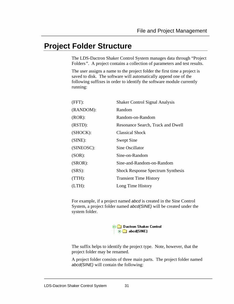
Project Folder Structure The LDS-Dactron Shaker Control System manages data through “Project Folders”. A project contains a collection of parameters and test results.
The user assigns a name to the project folder the first time a project is saved to disk. The software will automatically append one of the following suffixes in order to identify the software module currently running:
(FFT): Shaker Control Signal Analysis
(RANDOM): Random
(ROR): Random-on-Random
(RSTD): Resonance Search, Track and Dwell
(SHOCK): Classical Shock
(SINE): Swept Sine
(SINEOSC): Sine Oscillator
(SOR): Sine-on-Random
(SROR): Sine-and-Random-on-Random
(SRS): Shock Response Spectrum Synthesis
(TTH): Transient Time History
(LTH): Long Time History
For example, if a project named abcd is created in the Sine Control System, a project folder named abcd(SINE) will be created under the system folder.
The suffix helps to identify the project type. Note, however, that the project folder may be renamed.
A project folder consists of three main parts. The project folder named abcd(SINE) will contain the following:

File and Project Management
LDS-Dactron Shaker Control System 32
1. A project file: abcd.prj
2. An auxiliary project file: abcd.dat
3. “Run” folders
The project file abcd.prj contains all the display-related parameters and the file management information related to the project abcd(SINE). This file must be opened in order to load the project.
The auxiliary project file, abcd.dat, contains the measurement data in a compact binary format. It is always associated with the project file of the same name.
The Run folders contain test results. Whether a new Run folder is created each time the project is run depends upon the Save Signal Manager setup. The Run folders and the Save Signal Manager will be discussed in more detail later on.
Creating a New Project To create a new project, the user can either click on New under the Project menu or alternatively click on the New Project icon using the Toolbar Icons.
Creating a New Project thru the Project Menu
When a new Project is created, a temporary folder is established. This temporary folder will be renamed to the project name specified by the user upon saving.

File and Project Management
LDS-Dactron Shaker Control System 33
The “Project New” dialog box that appears next and also lists the Shaker Control tests available to the user (e.g. Sine, Random, Shock etc.) will depend upon two conditions. 1. The User Interface Configuration. 2. Test Setup Wizard Configuration.
More detail on setting up a new Project is discussed in Section 4, Define a Project.
User Interfaces
The LDS-Dactron Shaker Control software has two user interfaces from which the user can choose:
• Simple User Interface (SUI) • Advanced User Interface (AUI)
Note: If the Simple User Interface ONLY option was elected during the installation of this software, then the user must reinstall the software to obtain the Advance User Interface.
The user interface chosen determines the setup options available to the user when running the software.
Simple User Interface (SUI) Due to the complexity of some shaker control applications, the Advanced User Interface can be a very powerful tool in achieving one’s goals. However, some applications do not require many of the advanced setup features and parameter settings available in AUI and only get in the way while setting up the test. Both Random (basic) and Swept Sine are examples of such tests. For these two tests in particular, the SUI can be more useful to the user. Hence, Simple User Interface applies only to Random and Swept Sine tests. The following section, Differences Between SUI and AUI, highlights the differences between the two interfaces so that you can determine the interface that best suits your application.
File and Project Management
LDS-Dactron Shaker Control System 34
For more details on using the Simple User Interface please refer to the Simple User Interface User’s Manual.
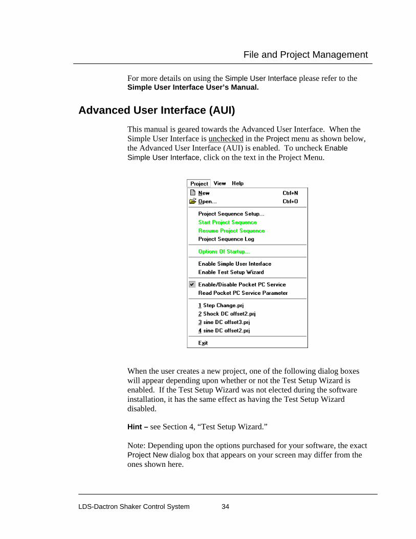
Advanced User Interface (AUI) This manual is geared towards the Advanced User Interface. When the Simple User Interface is unchecked in the Project menu as shown below, the Advanced User Interface (AUI) is enabled. To uncheck Enable Simple User Interface, click on the text in the Project Menu.
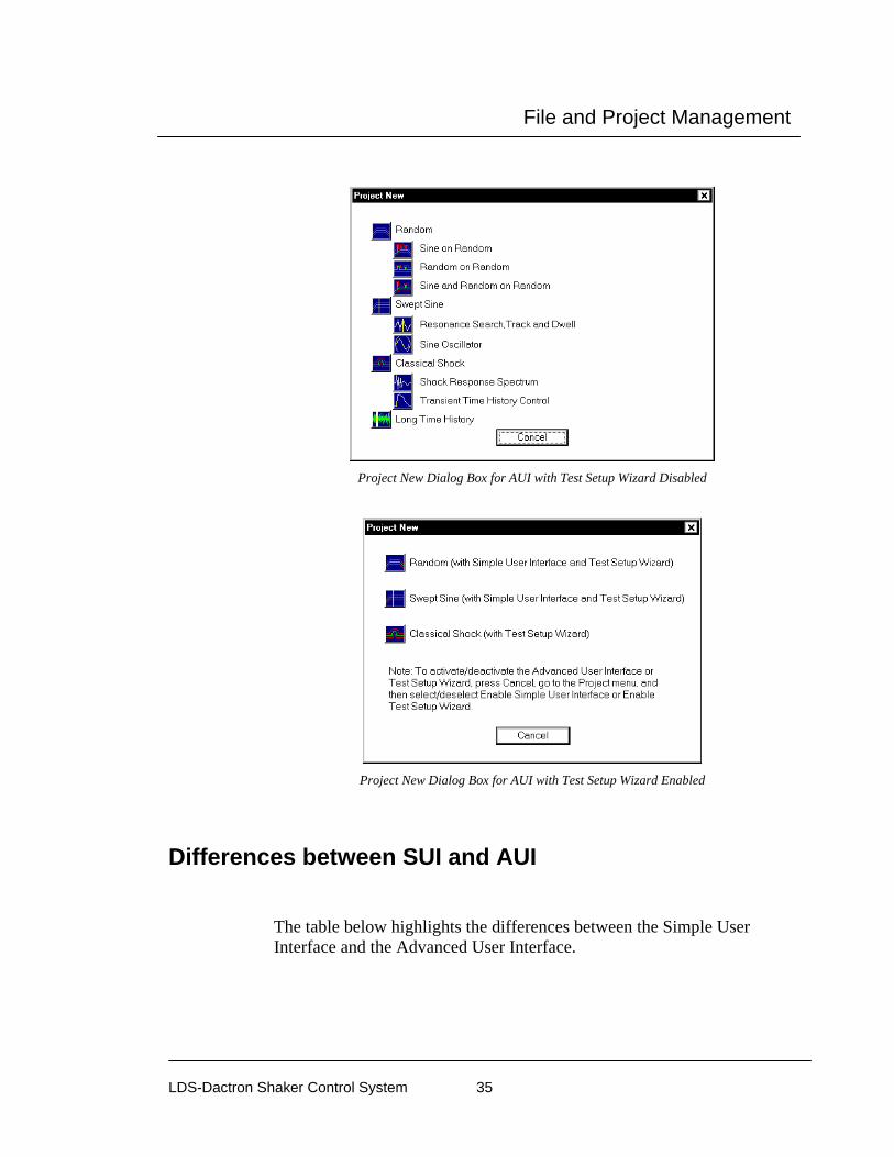
When the user creates a new project, one of the following dialog boxes will appear depending upon whether or not the Test Setup Wizard is enabled. If the Test Setup Wizard was not elected during the software installation, it has the same effect as having the Test Setup Wizard disabled. Hint – see Section 4, “Test Setup Wizard.” Note: Depending upon the options purchased for your software, the exact Project New dialog box that appears on your screen may differ from the ones shown here.
File and Project Management
LDS-Dactron Shaker Control System 35
Project New Dialog Box for AUI with Test Setup Wizard Disabled
Project New Dialog Box for AUI with Test Setup Wizard Enabled
Differences between SUI and AUI
The table below highlights the differences between the Simple User Interface and the Advanced User Interface.

File and Project Management
LDS-Dactron Shaker Control System 36
Feature Advanced Simple Notes Menus Project
Test Setup Profile Test Controls Report Window Pane Cursor Help
Project Settings Operations Display Help
Test Setup and Profile are combined in the Settings menu. Test and Controls are combined in the Operation menu. Window, Pane and Cursor are combined in the Display menu.
Mission Profiling
Project Sequencing can automatically initiate any list of defined projects. Block Diagram feature can automatically initiate several different profiles and schedules within one project type, e.g., Random or Sine.
Project Sequencing not available in SUI. Block Diagrams not available in SUI.
Report Customize and Create Quick Report located under the Report menu
Report menu removed. Report Settings and Create Report moved to the Project menu.
User cannot customize the report contents. Current Pane, Project Report, Output Saved Results to MS Word not available in SUI.
Window Menu
Window Menu includes One, Two, and Four Pane, Channel Status, Composite, Digital Input Monitor and Run Log
Window features moved to the Display menu and includes Composite, Input Time Signals, Input Frequency Signals, Inverse Transfer Function Window, Drive(f), and One Pane
Only One Pane windows are available in SUI. Run Log
Pane Menu
Pane features moved to the Display menu

File and Project Management
LDS-Dactron Shaker Control System 37
Open an Existing Project To open an existing project, go to the Project menu and select Open or click on the Open icon located on the icon toolbar.
The Open dialog box for the System Folder will appear from which you can select the desired project.
Open Dialog Box with the abcd(Sine) Project Folder Selected
To open the project abcd(SINE) for example, double-click on the abcd(SINE) folder. Once the folder is opened, highlight the abcd.prj file and click the Open button or double-click on the file abcd.prj to open the project.
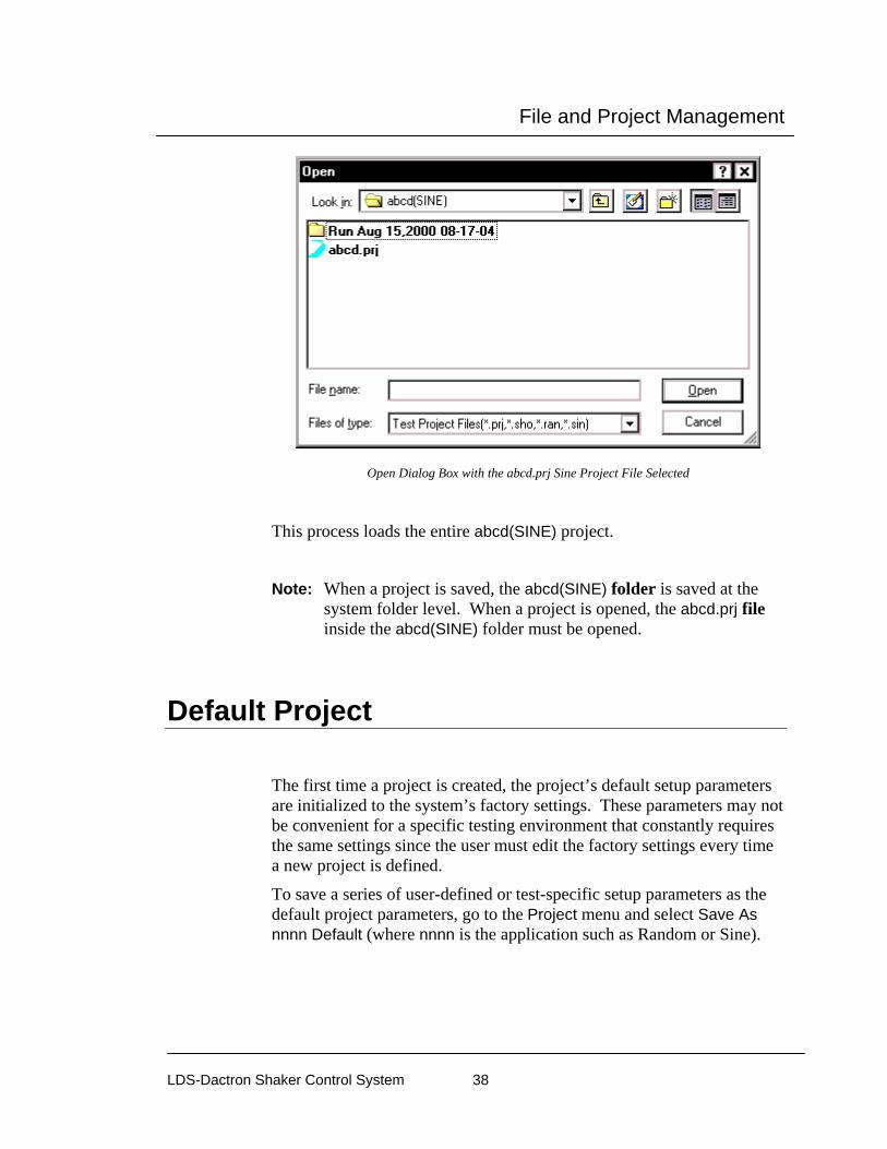
File and Project Management
LDS-Dactron Shaker Control System 38
Open Dialog Box with the abcd.prj Sine Project File Selected
This process loads the entire abcd(SINE) project.
Note: When a project is saved, the abcd(SINE) folder is saved at the
system folder level. When a project is opened, the abcd.prj file inside the abcd(SINE) folder must be opened.
Default Project
The first time a project is created, the project’s default setup parameters are initialized to the system’s factory settings. These parameters may not be convenient for a specific testing environment that constantly requires the same settings since the user must edit the factory settings every time a new project is defined.
To save a series of user-defined or test-specific setup parameters as the default project parameters, go to the Project menu and select Save As nnnn Default (where nnnn is the application such as Random or Sine).

File and Project Management
LDS-Dactron Shaker Control System 39
Saving Project Parameters as the Defaults
Next, click on the Save As Default Now button to save your customized settings as the Default.
Saving Project Settings as Project Defaults Dialog Box
Once your customized settings are saved as the Default Project, any future project created in that control system (i.e. Sine, Random, etc.) will use those settings. The customized Default Project can be reset back to the factory settings at anytime by clicking on the Return to Manufacturer Default Settings button in the same dialog box.

File and Project Management
LDS-Dactron Shaker Control System 40
Each control system has its own default project parameters. In other words, if you customize the Default Project to a Sine project, the parameters of the default Random project will still reflect the factory settings.
Run Folders
Run Folders serve as the location to which all information pertaining to a particular run can be stored. Such information includes signals, run logs, pane-information, screen captures, and report files. Creating Run Folders is accomplished using the Save Manager, which is the following topic. It is important to note that Run Folders are strictly the location to which information will be stored and that the user still must select what information will go into these folders. Otherwise, the Run Folder will only contain the run log file and the test composite – which may not be very useful to the user. Saving information and data will be discussed later on in the Signal Files section
Example of Run Folders with the Default Folder Name & Date and Time Stamp
If the user has not yet saved the current project, the Run Folder(s) will be created in the software’s common Bin\Temp\ folder. Since, this Temp folder can possibly contain an array of Run Folders from other projects that are not relevant to the current one, it is highly suggested that you save your project before running a new test.
Signal Manager The Signal Manager is accessed by pressing the button on the toolbar or from the drop-down menu on the toolbar. The Project menu also accesses specific tabs of the Signal Manager through its Save Data, Recall Data and Cache Data choices.
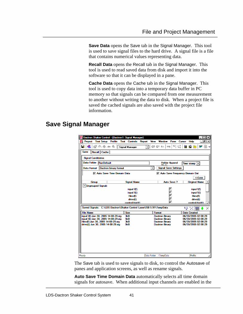
File and Project Management
LDS-Dactron Shaker Control System 41
Save Data opens the Save tab in the Signal Manager. This tool is used to save signal files to the hard drive. A signal file is a file that contains numerical values representing data.
Recall Data opens the Recall tab in the Signal Manager. This tool is used to read saved data from disk and import it into the software so that it can be displayed in a pane.
Cache Data opens the Cache tab in the Signal Manager. This tool is used to copy data into a temporary data buffer in PC memory so that signals can be compared from one measurement to another without writing the data to disk. When a project file is saved the cached signals are also saved with the project file information.
Save Signal Manager
The Save tab is used to save signals to disk, to control the Autosave of panes and application screens, as well as rename signals.
Auto Save Time Domain Data automatically selects all time domain signals for autosave. When additional input channels are enabled in the
File and Project Management
LDS-Dactron Shaker Control System 42
Channel Parameters dialog their corresponding time domain signals are automatically added to the Auto Save list.
Auto Save Frequency Domain Data automatically selects all frequency domain signals for autosave. When additional input channels are enabled in the Channel Parameters dialog their corresponding frequency domain signals are automatically added to the Auto Save list.
More/Less button displays or hides the list of available signals from the display.
Folder Append Mode defines where the data is saved. The following options are available:
Time Stamp – When Folder Append mode is set to Time Stamp and a measurement is started, a new folder is created with the folder name including the date and time. For example, if the project is saved as C:\LDS-Dactron\Shaker Control\My Test.prj, then the data folder will be C:\LDS-Dactron\ Shaker Control\My Test\RunDefault Jan 01,2002 12:12:12.
Overwritten – When Folder Append Mode is set to Overwritten and a measurement is started, the prior contents of the RunDefault folder will be deleted and new data will be added to the RunDefault folder. This mode is intended for troubleshooting and setup only.
Increment - When Folder Append Mode is set to Increment and a measurement is started, a new folder is created with the folder name including an incremented number. For example, if the project is saved as C:\LDS-Dactron\ Shaker Control\My Test.prj, then the data folder will be C:\LDS-Dactron\ Shaker Control\My Test\RunDefault1.
Consolidated - When Folder Append Mode is set to Consolidated and a measurement is started, a new folder is created with the folder name and path specified in the Data Folder field. Note the user can either type in the exact path into the Data Folder field or use the Browse button to locate the folder. Data will always be placed in this folder even after consecutive measurements are started.
Data Folder defines the name and path of the folder used to store data. When the Folder Append Mode is set to Date and Time or Increment then Data Folder can be any name. When Folder Append Mode is set to Consolidated then Data Folder must be a path and file name.

File and Project Management
LDS-Dactron Shaker Control System 43
Data Format defines the format that the data file will be saved in.
LDS-Dactron Binary is the system’s default data import and export format. This format preserves all the information about the data including measurement parameters. This compact file format also minimizes the disk space required to save signal data.
LDS-Dactron ASCII Delimited files include minimal header information such as the frame size, the sampling rate, etc., written in ASCII Format. Note that there are two types of LDS-Dactron ASCII Tab Delimited data formats: (1) Y-data only or (2) X-Y pair. All data fields are tab delimited for these formats.
ASCII formats are useful for providing data that can easily be read into other analysis programs such as spreadsheets. Data saved as X-Y pairs writes the time or frequency values as the X column and the amplitude values as the Y column. For example, a PSD saved in this format would have frequency values in the X column and PSD amplitude values in the Y column.
Below is an example of a signal in LDS-Dactron ASCII Tab Delimited X-Y pair format: $$$Note: Please don’t modify this file if you want to import it into LDS-Dactron software.$$$ Generated from LDS-Dactron Shaker Control software. Version 1.0 Signal name: input1(t) Original generated time: 18:04:54, April 17,1999 Current saving time: 11:39:47, April 20,1999 Signal format: ASCII Tab Delimited ‘X-Y Pair’ Sampling Frequency: 3000 Hz Block size: 4096 X axis start value: 0 X axis increment (Delta): 0.000333333 X axis increases by Linear step Time (seconds) Y(m/s2) 0.000000 0.000000 0.000333 0.120000 0.000667 0.120000 0.001000 0.340000 0.001333 0.564000 0.001667 0.004560 0.002000 0.000000 … Signal data file names consist of the signal name, such as H1_1,2(f), plus one of three types of labels. The first label is a date and time stamp. The second option is to use the run sequence number. The third is to use only the signal name without an appended label. In this case, be aware that since the

File and Project Management
LDS-Dactron Shaker Control System 44
file name is not unique, it will be overwritten if you save multiple times during a measurement.
UFF text format (SI Units) is a data file format that is commonly used for dynamic and vibration systems analysis. The text format is saved as an ASCII text file and is in SI Units.
UFF binary format (SI Units) is a data file format that is commonly used for dynamic and vibration systems analysis. The binary format is saved as a binary file and is in SI Units.
WAV Audio format is a digital audio file that can be played back using a digital audio player or PC. Note waveform amplitude is not preserved in the WAV format and WAV files cannot be recalled into LDS-Dactron software.
Agilent SDF Format (Standard Data Format) is a binary data file that is an open format used with many Agilent and HP devices. The structure is published and maintained by Agilent.
Note: MTS ATI/AFU and RPCIII formats are only available on Windows 2000 operating system and are not available in others. Shaker Control is not able to recognize MTS ATI/AFU files set with a “Read-only” attribute as defined in the MTS library. Please ensure prior to attempting to recall MTS ATI/AFU files in Shaker Control that the "Read-only" attribute has been disabled for these files.
MTS ATI format is a binary file used with IDEAS software.
MTS AFU format is a binary file used with MTS Noise Path Analysis software.
MTS RPCIII format is a binary file used with MTS Remote Parameter Control Simulation Testing, Analysis, and Control System software.
The table below summarizes the file formats that are supported in the Shaker Control Software (VCS).
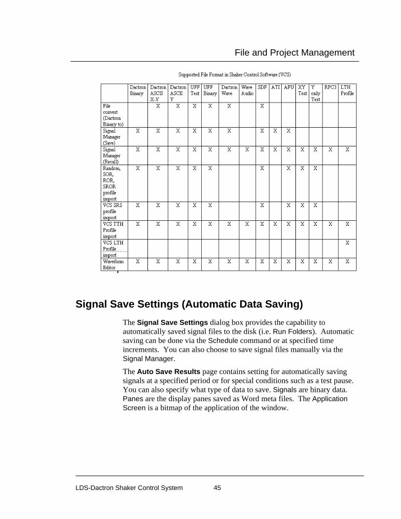
File and Project Management
LDS-Dactron Shaker Control System 45
Signal Save Settings (Automatic Data Saving) The Signal Save Settings dialog box provides the capability to automatically saved signal files to the disk (i.e. Run Folders). Automatic saving can be done via the Schedule command or at specified time increments. You can also choose to save signal files manually via the Signal Manager.
The Auto Save Results page contains setting for automatically saving signals at a specified period or for special conditions such as a test pause. You can also specify what type of data to save. Signals are binary data. Panes are the display panes saved as Word meta files. The Application Screen is a bitmap of the application of the window.
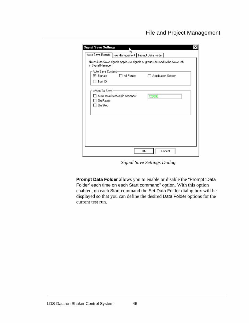
File and Project Management
LDS-Dactron Shaker Control System 46
Signal Save Settings Dialog
Prompt Data Folder allows you to enable or disable the “Prompt ‘Data Folder’ each time on each Start command” option. With this option enabled, on each Start command the Set Data Folder dialog box will be displayed so that you can define the desired Data Folder options for the current test run.

File and Project Management
LDS-Dactron Shaker Control System 47
Append Mode defines how the data is saved. For details on this feature refer to Section 3, Save Signal Manager.
Data Folder defines the name and path of the folder used to store data. For details on this feature refer to Section 3, Save Signal Manager. The format of Data Folder is Project Folder\Related Folder.
Related Folder defines the name of the Data Folder. This can also be defined in the Data Folder field in the Save Signal Manager.
Project Folder defines the name and path of the folder used to store your project files.
Prompt to set the data folder on each Start command allows you to disable the prompt on a Start command.
File Management
The File Management tab allows you to control the format of the signal file naming by adding appendages to the file names of signal data files. The appendage allows you to distinguish between signal data files that are saved several times due to multiple runs. For example, if the user selects to save the time response input1(t) in LDS-Dactron binary format every time for 5 runs, adding the “Append increment number…” starting at “1” would produce input1(t) 1.sig, input1(t) 2.sig, input1(t) 3.sig, etc.
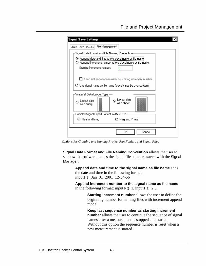
File and Project Management
LDS-Dactron Shaker Control System 48
Options for Creating and Naming Project Run Folders and Signal Files
Signal Data Format and File Naming Convention allows the user to set how the software names the signal files that are saved with the Signal Manager.
Append date and time to the signal name as file name adds the date and time in the following format: input1(t)_Jan_01_2001_12-34-56 Append increment number to the signal name as file name in the following format: input1(t)_1, input1(t)_2…
Starting increment number allows the user to define the beginning number for naming files with increment append mode. Keep last sequence number as starting increment number allows the user to continue the sequence of signal names after a measurement is stopped and started. Without this option the sequence number is reset when a new measurement is started.

File and Project Management
LDS-Dactron Shaker Control System 49
Use signal name as file name allows the user to save the signals using the signal names. With this option it is easy to save a signal with the same name every time and therefore overwrite data.
Waterfall Data Layout Type allows the user to define the format of waterfall data that is saved in ASCII format.
Layout data as query places all the data in a single column.
Layout data as a sheet places the data in rows and columns with each z slice in a different column.
Using More/Less to Enable Signal Saves When the More button is pressed the Signal Manager dialog exposes a table that shows the signal candidates that can be saved and various other options and information.
Signal Name lists all signals that are available to save. There are 2 methods for saving signals:
A Manual Save can be performed at any time during or after a test. To perform a Manual Save, the user selects the desired signals by clicking one signal name, Ctrl+click several signal names, Shift+click several signal names, or click+drag an area to select several signal names. After the signals are selected the user can drag the selected signals from the Signal Candidates list, down to the Saved Signals list. When the signal appears in the Saved Signals list then it has been written to disk. Also the user
can click on the green arrow button to save all selected

File and Project Management
LDS-Dactron Shaker Control System 50
signals. The path is listed above the Save Signals list to show where the files are saved.
An Auto Save is normally executed on an autosave event. The Auto Save Settings indicates which signals will be saved on an autosave event. Click on the check boxes under Auto Save to specify which signals to save on an autosave event. Autosave events can be set by selecting Signal Save Settings from the Test Setup menu, by doing a right-click operation on your mouse on any signal in the Signal Candidates pane, or by clicking on Signal Save Settings in the Save Signal Manager. This opens the Signal Save Settings dialog.
Auto-Save Results allows the user to define when an auto-save event will occur.
In addition to programmed response to autosave events, an Auto Save can also be manually triggered by pressing F7 on the keyboard or clicking on the Auto Save icon on the toolbar .
Original Name lists the names of signals before any changes are made to the name of the signals listed under Signal Name. In order to change the name of a signal, simply do a right-click operation on your mouse on the signal under the Signal Name list and select Rename Signal. You can then type in the new name desired.
Group allows the user to define groups to organize several signals into one file, which reduces the number of files saved to disk. Signal Groups can only contain signals of the same type, for example all Real Time signals. Signals of different types can not be combined into one Signal Group. For example Real Time and FFT signals can not be combined into one Signal Group. Grouped signals are always saved in SDF format. Group lists all the define groups.

File and Project Management
LDS-Dactron Shaker Control System 51
After a group is defined, clicking on the icon collapses the list to conserve space on the Save Signal Manager. Clicking on the icon expands a collapsed group.
To define a new group, right click on any group or the Ungrouped Signals list to open the group pop up menu and select Create Group. This opens the Create Group dialog.
Enter Group Name allows the user to define the name of the group. Set Data Type allows the user to automatically add all signals of one type to the new group. Place a check next to Add all this type signal to the new group, and select a Data Type, and click OK. Other group functions are available from the group pop up menu. Add All Same Type Signals opens the Set Data Type dialog.

File and Project Management
LDS-Dactron Shaker Control System 52
Date Type defines the signal type that will be added to the group. Delete Group removes the current group. All signals in the group are returned to the ungrouped list. Rename Group allows the user to change the name of the group. After a group is created, signals can be added by right clicking on a signal and selecting Add to Group and then select the group name from the sub menu. A signal can be removed from a group by right clicking on the signal and selecting Remove from Group.
Recall Signal Manager The Recall Signal Manager allows the user to recall previously saved signal files (i.e. files in LDS-Dactron recognized formats including: *.sig, *.txt, or *.uff, etc.). This facility replaces the Recall option and RSM facilities of prior releases. The user also has the option to rename recalled signals so that the Signal Name is different from the saved Original Name. It can be accessed from the Project menu or using the Recall button on the toolbar.
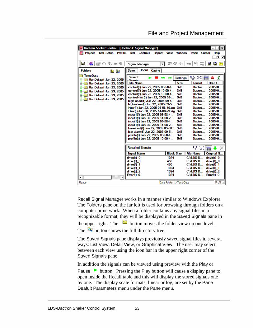
File and Project Management
LDS-Dactron Shaker Control System 53
Recall Signal Manager works in a manner similar to Windows Explorer. The Folders pane on the far left is used for browsing through folders on a computer or network. When a folder contains any signal files in a recognizable format, they will be displayed in the Saved Signals pane in the upper right. The button moves the folder view up one level. The button shows the full directory tree.
The Saved Signals pane displays previously saved signal files in several ways: List View, Detail View, or Graphical View. The user may select between each view using the icon bar in the upper right corner of the Saved Signals pane.
In addition the signals can be viewed using preview with the Play or Pause button. Pressing the Play button will cause a display pane to open inside the Recall table and this will display the stored signals one by one. The display scale formats, linear or log, are set by the Pane Deafult Parameters menu under the Pane menu.

File and Project Management
LDS-Dactron Shaker Control System 54
The Settings button defines how the signals are previewed.
Mode defines how the preview images are updated. When Auto is selected then all signals in the folder are displayed one at a time for the time selected in the Persistence setting. When Manual is selected then the highlighted signal is previewed until ether of the buttons are selected to advance to the previous or next signal. The preview mode can be stopped by clicking on the button.
Another way to display recalled data is to simply select a signal by clicking on it so it is highlighted or using shift click to highlight a range of signals, and then doing a drag and drop to an open display pane. This method is illustrated by the screen captures that follow.

File and Project Management
LDS-Dactron Shaker Control System 55
List View enumerates each signal file by File Name, Size, Format, and Time/Date stamp as shown above.

File and Project Management
LDS-Dactron Shaker Control System 56

File and Project Management
LDS-Dactron Shaker Control System 57
Detail View displays information about each data file in a colored text box. Similar signal types are displayed with the same colored text box. The file name is displayed below the text box. The information includes: the function symbol, date & time stamp, function description, number of data points, resolution, and file format.
Graphical View displays each signal file as an icon and also displays the same information as Detail View, but with the addition of an envelope preview of the signal. NOTE: This preview represents a rough envelope of the actual signal since it is limited to only 120 points. Also, the preview is displayed on a linear axis.

File and Project Management
LDS-Dactron Shaker Control System 58
You can right-click on any signal, select View from the pop-up menu in any of the 3 views to open a pop-up window over the middle of the Saved Signals pane. This display shows a large plot of the data auto scaled with axis labeled. Below the graph is all the header information. The display is shown until the user clicks once on the display to close it. The user can quickly right click, select View on each signal until the desired signal is found.
You can also right-click on any saved signal and convert it to a different format. You can do this by selecting Save As from the pop-up menu in the List View to open the Browse For Folder dialog. You can then specify the location to save the signal to.

File and Project Management
LDS-Dactron Shaker Control System 59
To recall a saved signal file, highlight the desired signal by clicking on it
and use the green arrow button to import that signal into the Recalled Signals window or simply double click on the desired signal. Multiple signals can be selected by holding down the Ctrl key on the keyboard and clicking additional files.
The requested signal will then be imported into the Recalled Signals bin with an added numerical extension (_0, _1, _2…) to the signal name. This extension allows the user to differentiate it from any current test signals in the Contents window since the same signal name can be recalled several times.
If an unwanted signal is selected inadvertently, either single click on that signal file in the Recalled Signals pane and press the “Delete” button your keyboard or highlight it by clicking on it and use the red button to remove the signal from the pane.
After the signal is recalled it does not appear in a new pane until the user adds the recalled signal to a new pane. One or several signals can be selected and dragged from the Signal Manager into an existing pane. Another approach that can be used is to select a pane, or create a new pane, and then open the Contents dialog by right clicking. All signals that were listed in the Recalled Signals bin should now also be listed in the Select Signals to Display field in the Contents window and available to be recalled into the pane.
Cache Signal Manager The Cache Signal Manager can be accessed by clicking on the tab in the upper left corner of the Signal Manager. When a signal is cached, it is put into RAM memory, but not saved to disk. Cached signals can easily be compared to live measured signals. It is a convenient tool for comparing successive measurements.
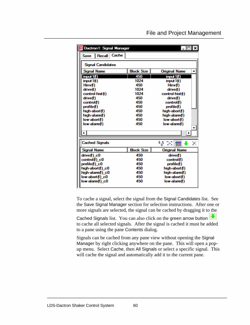
File and Project Management
LDS-Dactron Shaker Control System 60
To cache a signal, select the signal from the Signal Candidates list. See the Save Signal Manager section for selection instructions. After one or more signals are selected, the signal can be cached by dragging it to the
Cached Signals list. You can also click on the green arrow button to cache all selected signals. After the signal is cached it must be added to a pane using the pane Contents dialog.
Signals can be cached from any pane view without opening the Signal Manager by right clicking anywhere on the pane. This will open a pop-up menu. Select Cache, then All Signals or select a specific signal. This will cache the signal and automatically add it to the current pane.

File and Project Management
LDS-Dactron Shaker Control System 61
Saving using the Schedule
After selecting which signals will be auto-saved from the Save Signal Manager, you can use the project schedule to invoke automatic saving. Automatic saving using the Schedule consists of adding Save Results events (Auto-Save Signals, Save Active Pane, Save All Panes, & Save Screen Bitmaps) to the Schedule such that every time the Schedule is active, one or more save events will occur. Select “Save Results…” from the Schedule dialog box to add a Save Results event to the Schedule.
Selecting Save Results… from the Schedule
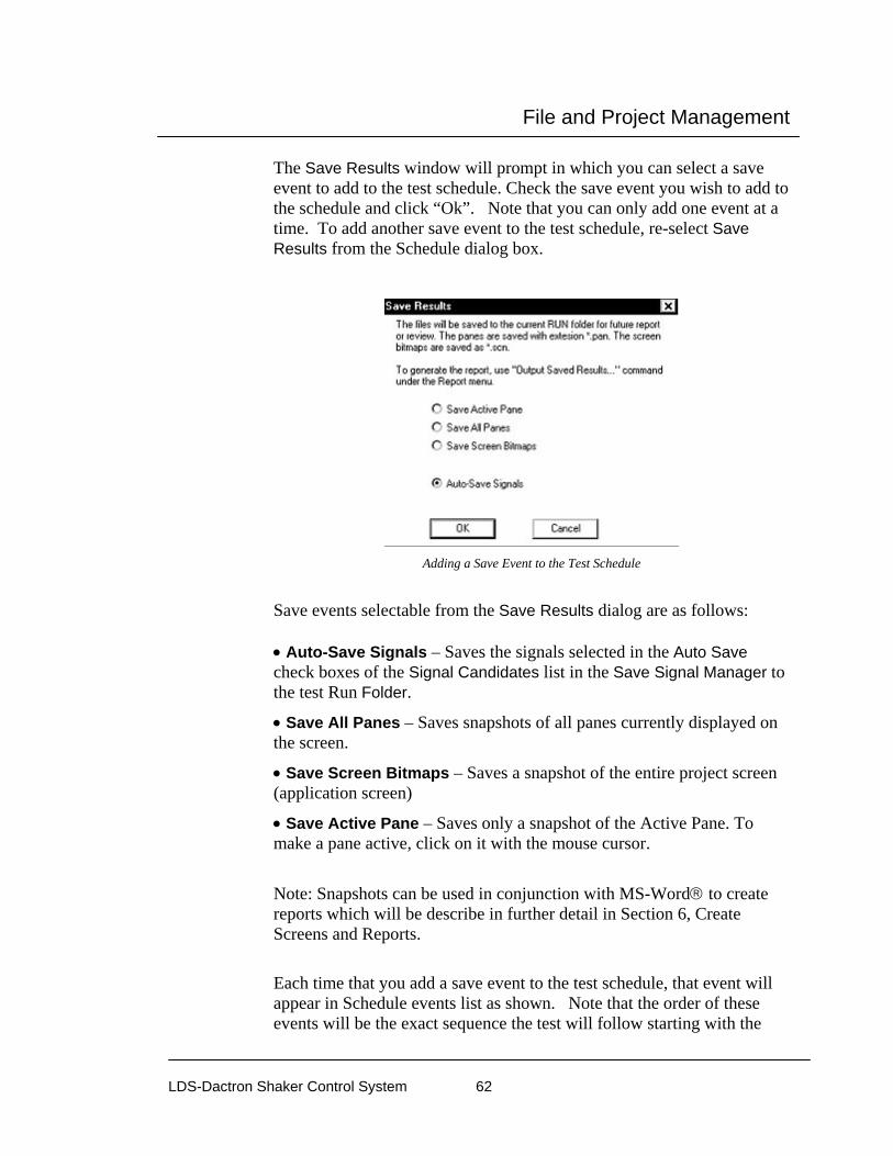
File and Project Management
LDS-Dactron Shaker Control System 62
The Save Results window will prompt in which you can select a save event to add to the test schedule. Check the save event you wish to add to the schedule and click “Ok”. Note that you can only add one event at a time. To add another save event to the test schedule, re-select Save Results from the Schedule dialog box.
Adding a Save Event to the Test Schedule
Save events selectable from the Save Results dialog are as follows: • Auto-Save Signals – Saves the signals selected in the Auto Save check boxes of the Signal Candidates list in the Save Signal Manager to the test Run Folder.
• Save All Panes – Saves snapshots of all panes currently displayed on the screen.
• Save Screen Bitmaps – Saves a snapshot of the entire project screen (application screen)
• Save Active Pane – Saves only a snapshot of the Active Pane. To make a pane active, click on it with the mouse cursor.
Note: Snapshots can be used in conjunction with MS-Word® to create reports which will be describe in further detail in Section 6, Create Screens and Reports.
Each time that you add a save event to the test schedule, that event will appear in Schedule events list as shown. Note that the order of these events will be the exact sequence the test will follow starting with the

File and Project Management
LDS-Dactron Shaker Control System 63
event at the top of the list. In other words, when the test is started, the first event that will occur will be the event at the top of the Schedule events list, followed by the event directly below it. Therefore, it is most likely that you will want to place the save events at the end of the schedule – after the test has completed.
Test Schedule Showing Event Sequence
All of the items that are scheduled to be saved should appear in the Run Folder at the completion of the test.
Signal Files Signal Files are files that contain the numerical information of any signal that is selectable from the Signal Candidates field of the Contents dialog box – including the Control Profile, Drive Signal, Inputs Signals, Abort Limits, Hinv, etc. Typically, signals that are unaveraged represent one frame of data. Control(f) and input(f) are examples of averaged signals, which are the result of many frames. Furthermore, Signals can be displayed in a pane, saved to disk in a specified format, or recalled from disk and re-displayed/overlaid.
In addition to the default signals that are available to a project, you may also create or import “Special” signals. Creating a special signal involves applying Math Operations such as Add, Subtract, Multiply, and Divide using the project’s default signals as operands. Importing a special signal entails importing a signal remotely where the imported signal was created using another application such as RT-Pro’s Acoustic Analysis. The topic of Special Signals and its applications will be discussed in further detail in Section 4, Define a Project.
The primary focus of this section will be to discuss the different types of default Signal Files accessible to you from the Signal Candidates field

File and Project Management
LDS-Dactron Shaker Control System 64
and also how to save Signals, either manually or automatically, into the Run Folders that were mentioned previously.
Warning: In Windows 95/98 the total number of files within a directory is limited to 20,480. Keep this in mind when setting up automatic disk storage of signal files. Also, it is a good practice to periodically backup Project Folders and Signal Files while cleaning out your file directories.
Signal File Types and Name Conventions In the LDS-Dactron Shaker Control System, a signal is defined as an array of data with an associated structure of attributes. The names of these signals are defined using the following conventions:
• Suffix “(t)” is appended to the signal name to indicate that the signal is in time domain.
• Suffix “(f)” is appended to the signal name to indicate that the signal is in frequency domain. For example, input n (f) is the frequency spectrum signal of channel n. In Random/SoR/RoR/SRoR, input n (f) is a PSD (Power Spectral Density). In Sine/Sine Oscillator/RSTD, input n (f) is an Amplitude Spectrum.
The following units are used for the various types of signals: • Time Domain Signal: Vertical Unit: EU (Engineering Units)
Horizontal Unit: Time in Seconds
• Power Spectral Density: Vertical Unit: EU2/Hz
Horizontal Unit: Frequency in Hz
• Amplitude Spectrum: Vertical Unit: EU in Peak
Horizontal Unit: Frequency in Hz
• SRS Signal: Vertical Unit: EU
Horizontal Unit: Frequency in Hz

File and Project Management
LDS-Dactron Shaker Control System 65
Random and Mixed-mode Signals
In Random/SoR/RoR/SRoR, the following signals are available:
• control(f): Control spectrum
• control-hist(t): Scrolling time history of the control signal amplitude
• profile(f): Target profile spectrum
• high-abort(f): High-line abort tolerance
• low-abort(f): Low-line abort tolerance
• high-alarm(f): High-line alarm tolerance
• low-alarm(f): Low-line alarm tolerance
• drive(f): Drive signal spectrum
• drive(t): Drive signal time history
• Hinv(f): Inverse system transfer function
• input n (f): Spectrum of the nth channel
• input n (t): Time history, or the time characteristic history of the nth channel
• kurtosis (t): Strip chart display of the kurtosis parameter for the control signal
In addition to the above signals, SoR and SRoR include the following signal choices: • envelope (f): Sweep profile for all of the tones
• profile tone n (f): Acceleration amplitude versus frequency profile for the nth tone
• control tone n (f): Acceleration amplitude versus frequency control signal for the nth tone
Other signals that are also available are any Special Signals or Transmissibility signals, which is explained in further detail in Section 4, Define a Project.
Note: The time characteristic history(t) signal is particularly useful for monitoring the test level as function of time. The type of level
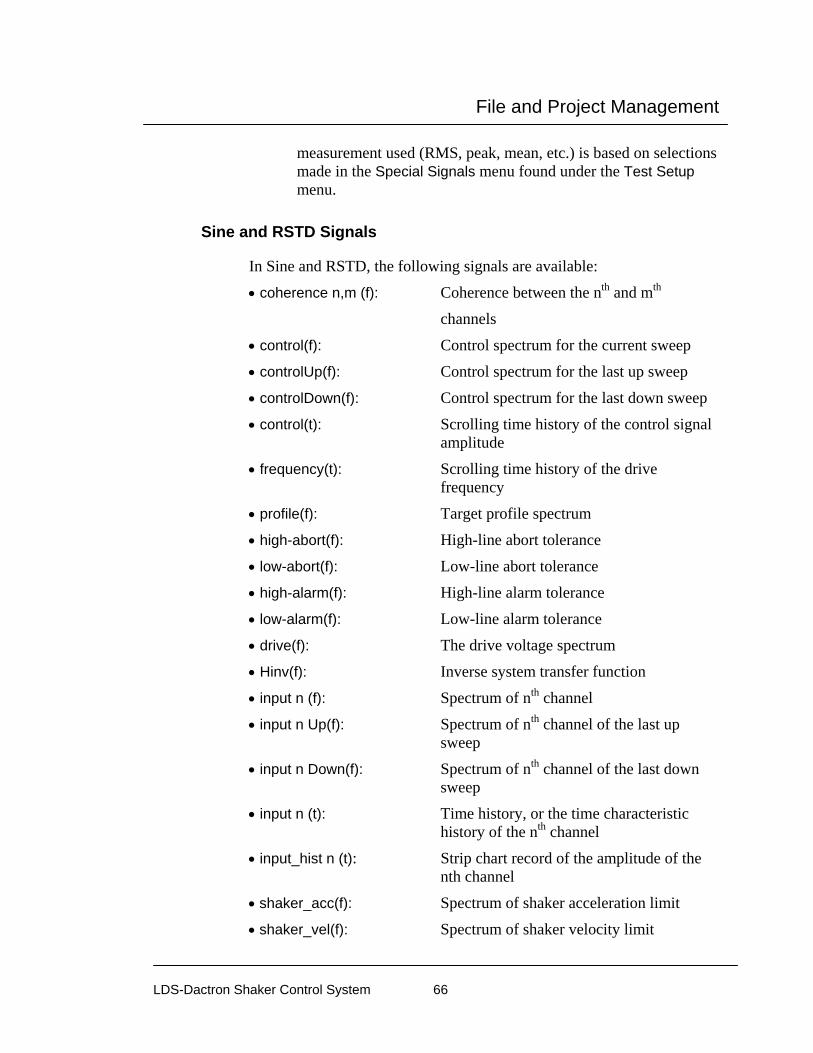
File and Project Management
LDS-Dactron Shaker Control System 66
measurement used (RMS, peak, mean, etc.) is based on selections made in the Special Signals menu found under the Test Setup menu.
Sine and RSTD Signals
In Sine and RSTD, the following signals are available:
• coherence n,m (f): Coherence between the nth and mth
channels
• control(f): Control spectrum for the current sweep
• controlUp(f): Control spectrum for the last up sweep
• controlDown(f): Control spectrum for the last down sweep
• control(t): Scrolling time history of the control signal amplitude
• frequency(t): Scrolling time history of the drive frequency
• profile(f): Target profile spectrum
• high-abort(f): High-line abort tolerance
• low-abort(f): Low-line abort tolerance
• high-alarm(f): High-line alarm tolerance
• low-alarm(f): Low-line alarm tolerance
• drive(f): The drive voltage spectrum
• Hinv(f): Inverse system transfer function
• input n (f): Spectrum of nth channel
• input n Up(f): Spectrum of nth channel of the last up sweep
• input n Down(f): Spectrum of nth channel of the last down sweep
• input n (t): Time history, or the time characteristic history of the nth channel
• input_hist n (t): Strip chart record of the amplitude of the nth channel
• shaker_acc(f): Spectrum of shaker acceleration limit
• shaker_vel(f): Spectrum of shaker velocity limit

File and Project Management
LDS-Dactron Shaker Control System 67
• shaker_disp(f): Spectrum of shaker displacement limit
• transmissibility n,m (f): Amplitude ratio and phase between the nth and mth channels
Other signals that are also available are any Special Signals or Transmissibility signals, which is explained in further detail in Section 4, Define a Project.
Note: 1. The sweep-up and sweep-down traces are available to both the control signal and the first four channel measurements. They can be used in computing transmissibility between these channels.
2. The default for all amplitude spectra in Sine, except for drive(f), is acceleration. However, you may view the data in terms of velocity or displacement by selecting the appropriate Dimension in the display setup.
Sine Oscillator Signals
In Sine Oscillator, the following signals are available:
• coherence n,m (f): Coherence between the nth and mth channels
• drive(f): The drive voltage spectrum
• frequency(t): Scrolling time history of the drive frequency
• input n (f): Spectrum of nth channel
• input_hist n (t): Strip chart record of the amplitude of the nth channel
• input n Up(f): Spectrum of nth channel of the last up sweep
• input n Down(f): Spectrum of nth channel of the last down sweep
• shaker_acc(f): Spectrum of shaker acceleration limit
• shaker_vel(f): Spectrum of shaker velocity limit
• shaker_disp(f): Spectrum of shaker displacement limit
• transmissibility n,m (f): Amplitude ratio and phase between the nth and mth channels

File and Project Management
LDS-Dactron Shaker Control System 68
Other signals that are also available are any Special Signals or Transmissibility signals, which is explained in further detail in Section 4, Define a Project.
Note: 1. The sweep-up and sweep-down traces are available to both the control signal and the first four channel measurements. They can be used in computing transmissibility between these channels.
2. The default for all amplitude spectra in Sine, except for drive(f), is acceleration. However, you may view the data in terms of velocity or displacement by selecting the appropriate Dimension in the display setup.
Classical Shock, SRS Synthesis, and TTH Signals
In Shock, SRS Synthesis, and TTH, the following signals are available:
• control(t): Control time waveform
• control(f): Response Spectrum of control(t)
• control(t)_scroll: Scrolling time history of the control signal amplitude
• profile(t): Target profile time waveform
• profile(f): Target profile spectrum
• high-abort(t): High-point abort time domain tolerance
• low-abort(t): Low-point abort time domain tolerance
• drive(t): Drive time waveform
• error(f): Error between the control signal and the profile in the frequency domain
• error(t): Error between the control signal and the profile in the time domain
• Hinv(f): Inverse system transfer function
• input n (t): Time history of nth channel
• NegSRSn(f): SRS of nth channel using maximum negative value extraction
• PosSRSn(f): SRS of nth channel using maximum positive value extraction
• MaxiMaxSRSn(f): SRS of nth channel using maximum absolute value extraction
File and Project Management
LDS-Dactron Shaker Control System 69
SRS Synthesis also provides these frequency domain signals: • high-abort(f): High-line SRS abort tolerance
• low-abort(f): Low-line SRS abort tolerance
Other signals that are also available are any Special Signals, which is explained in further detail in Section 4, Define a Project – Special Signals.
Long Time History (LTH) Signals
In Long Time History (LTH) Control, the following signals are available:
• control(t): Time history of the control signal
• control(f): Control spectrum
• control-hist(t): Scrolling time history of the control signal amplitude
• error-hist(t): Scrolling time history of the error signal amplitude
• profile-hist(t): Scrolling time history of the profile signal amplitude
• overall_control(f): Overall averaged control spectrum
• overall_error(f): Overall averaged error spectrum
• overall_profile(f): Overall averaged profile spectrum
• Hinv2(f): Inverse system transfer function
• Error(t): Time history of the error signal
• profile(t): Target profile time history
• profile(f): Target profile spectrum
• high-abort(f): High-line abort tolerance
• low-abort(f): Low-line abort tolerance
• drive(f): Drive signal spectrum
• drive(t): Drive signal time history

File and Project Management
LDS-Dactron Shaker Control System 70
• Hinv(f): Inverse system transfer function
• input n (t): Time history, or the time characteristic history of the nth channel
• input n (f): Spectrum of the nth channel
• Profile Output Index: This display shows the entire profile waveform with a sweeping, reverse-color cursor band that highlights the segment of the profile currently being output.
Other signals that are also available are any Special Signals or Transmissibility signals, which is explained in further detail in Section 4, Define a Project.
Note: The time characteristic history(t) signal is particularly useful for monitoring the test level as function of time. The type of level measurement used (RMS, peak, mean, etc.) is based on selections made in the Special Signals menu found under the Test Setup menu.
Pane Pop-Up Menu The Pane Pop-Up menu can be accessed from any pane by right clicking on the pane. It contains many features that are most commonly used and gives quick access to commonly used dialogs.

File and Project Management
LDS-Dactron Shaker Control System 71
Section 6, “Create Screens and Reports,” provides detailed descriptions of the functions available with the display pop-up menu.

Define a Project
LDS-Dactron Shaker Control System 72
4 Define a Project
Creating a New Project This section describes how to create a new Project by defining and setting up the test parameters and test profile. The next section, Section 5 – Run a Project, will explain how to use the Project you’ve set up to make a test run. If you are unfamiliar with a Project and its File structures, please read Section 3, “File and Project Management”, before attempting to create a Project. As you continue with this section, special attention should be made to the Project ToolBar as it can be considered the “root” of the project.
The Shaker Control Main Screen appears from which you can create a new project using the Start-Up Page or the Project menu.
Shaker Control Main Screen
Next, verify that the software is operating under the Advanced User Interface (AUI). In the Project Menu, ”Enable Simple User Interface” should be unchecked indicating that you are currently running Shaker
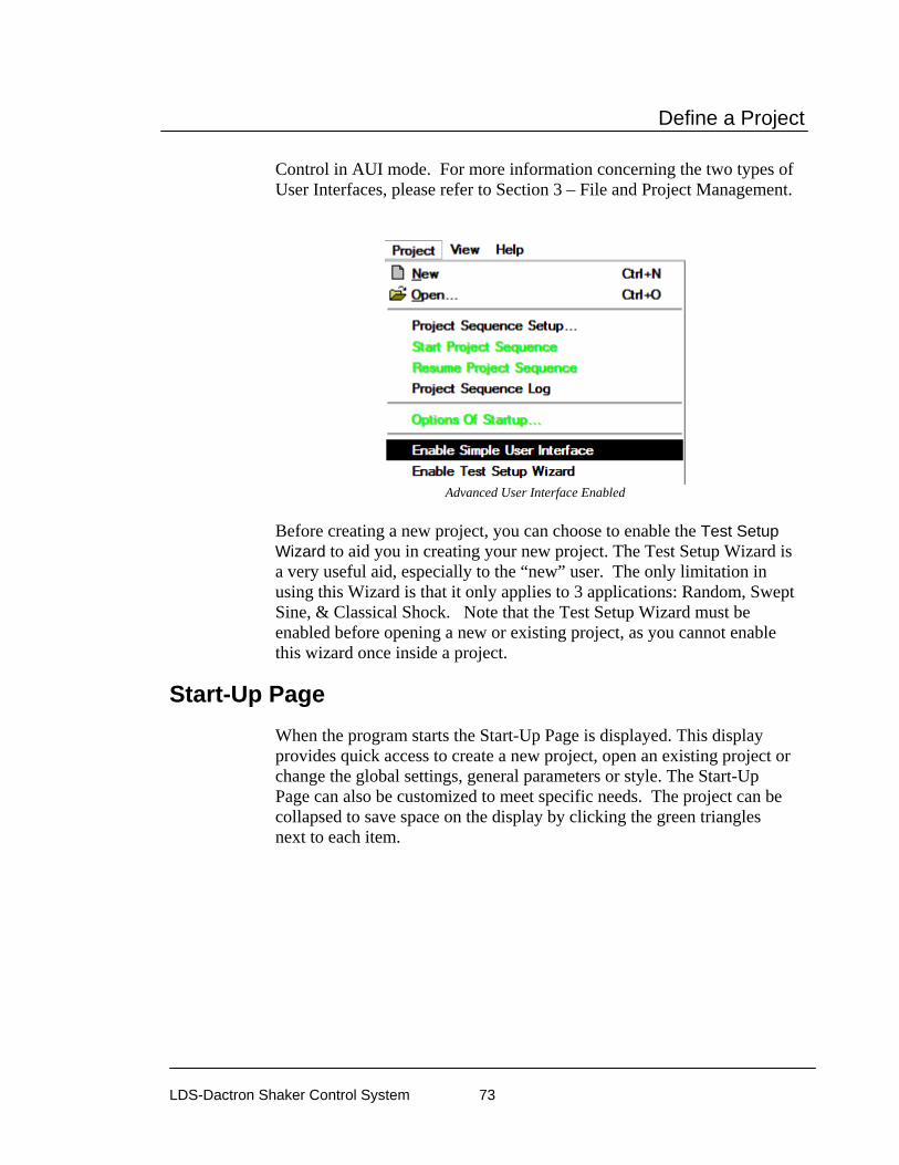
Define a Project
LDS-Dactron Shaker Control System 73
Control in AUI mode. For more information concerning the two types of User Interfaces, please refer to Section 3 – File and Project Management.
Advanced User Interface Enabled
Before creating a new project, you can choose to enable the Test Setup Wizard to aid you in creating your new project. The Test Setup Wizard is a very useful aid, especially to the “new” user. The only limitation in using this Wizard is that it only applies to 3 applications: Random, Swept Sine, & Classical Shock. Note that the Test Setup Wizard must be enabled before opening a new or existing project, as you cannot enable this wizard once inside a project.
Start-Up Page When the program starts the Start-Up Page is displayed. This display provides quick access to create a new project, open an existing project or change the global settings, general parameters or style. The Start-Up Page can also be customized to meet specific needs. The project can be collapsed to save space on the display by clicking the green triangles next to each item.
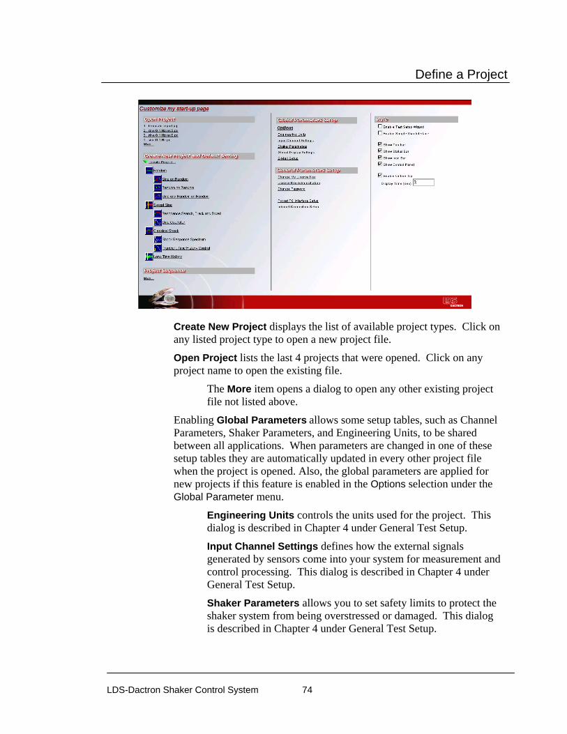
Define a Project
LDS-Dactron Shaker Control System 74
Create New Project displays the list of available project types. Click on any listed project type to open a new project file.
Open Project lists the last 4 projects that were opened. Click on any project name to open the existing file.
The More item opens a dialog to open any other existing project file not listed above.
Enabling Global Parameters allows some setup tables, such as Channel Parameters, Shaker Parameters, and Engineering Units, to be shared between all applications. When parameters are changed in one of these setup tables they are automatically updated in every other project file when the project is opened. Also, the global parameters are applied for new projects if this feature is enabled in the Options selection under the Global Parameter menu.
Engineering Units controls the units used for the project. This dialog is described in Chapter 4 under General Test Setup.
Input Channel Settings defines how the external signals generated by sensors come into your system for measurement and control processing. This dialog is described in Chapter 4 under General Test Setup.
Shaker Parameters allows you to set safety limits to protect the shaker system from being overstressed or damaged. This dialog is described in Chapter 4 under General Test Setup.
Define a Project
LDS-Dactron Shaker Control System 75
Global Display settings control the display attributes including color, line style, fonts, and axis formatting and scaling. This dialog is described in Chapter 6 under the Pane Menu section.
E-Mail Setup allows the software to send an email when the test aborts. This dialog is described in Chapter 4 under General Test Setup.
General Parameter Setup includes items for managing software and hardware licensing.
Change my License Key opens a dialog to change the license number. This can be used when multiple front end boxes are used on the same computer.
License Key Administration opens a dialog to choose from a list of different front end boxes. This dialog is described in Section 1 under Help Menu.
Change Password opens a dialog to change the current user password.
User Administration opens a dialog to add or change user information.
Group Administration opens a dialog to add or change group information.
Pocket PC Interface Setup opens a dialog to enable the Pocket PC Interface and enter the TCP/IP port settings.
Internet Connection Setup opens a dialog to define the Web Service URL and connection password.
Style changes the display settings for all project files opened. The following items can be enabled or disabled: Test Setup Wizard, Simple user Interface, Tool Bar, Status Bar, Icon Bar, Control Panel and Online Tip.
Customize my start-up page allows the contents of the Start-Up Page to be customized. Click Customize my Start-Up Page to open the dialog. The Start-Up Page can be organized into 3 columns. The window at the bottom displays group items that are removed from the current display. Items may be dragged from the current location to a different location by clicking and dragging. The order of the items can be changed within a column by selecting the item and clicking the up or down arrow at the top of the column. An item can be removed by selecting it and clicking on the button at the top of the column.

Define a Project
LDS-Dactron Shaker Control System 76
Customize my start-up page dialog
The settings for each group can be edited by double clicking on the item, or selecting it and clicking on the Group Setting button. This opens a dialog for the specific group item where the group settings can be enabled or removed from the display.
Font Size changes the font size of all text on the Start-Up Page.
Clear All removes all items from the Start-Up Page.
Default returns the Start-Up Page to the factory settings.
Preview shows what the current Start-Up Pages will look like.
Test Setup Wizard The Test Setup Wizard is an interface that guides you step-by-step through a test setup procedure for 3 specific applications– Random, Swept Sine, or Classical Shock. Other tests such as Random-on-Random, RSTD, Transient Time History (TTH), etc. must be setup manually. Moreover, when the Test Setup Wizard is enabled, you will only be able to create one of the three applications mentioned. To use the Test Setup Wizard, it must be enabled in the Project Menu when you first start the LDS-Dactron Shaker Control software and BEFORE you open a project. To enable the Test Setup Wizard, go to the Project menu

Define a Project
LDS-Dactron Shaker Control System 77
from the Shaker Control Main Screen and click on Enable Test Setup Wizard such that a check mark appears next to the menu item. Once selected, this feature will always be enabled until the user disables it, even after closing the Shaker Control software.
Project Menu from Shaker Control Main Screen
When the Test Setup Wizard is enabled, you will only be able to select Random, Swept Sine, or Classical Shock projects from the Project New dialog as shown below.
New Project Menu - Test Setup Wizard Enabled
Upon selecting from one of the three tests, the Test Setup Wizard window immediately appears in the opening screen as shown below. Displayed on this window are the set-up parameters required for the test along with instructions and setup descriptions. Any setup parameter that has not been reviewed by the user will have a “red” indicator light above that icon.

Define a Project
LDS-Dactron Shaker Control System 78
To setup a particular parameter, you may either click on Set or click on the parameter icon itself. Doing so will open the appropriate setup field from which you can then enter/customize the associated setup parameters. When finished, click OK to return to the Wizard. To continue onto the next setup parameter, click on Next and repeat the previous steps. For more detail on setting up the Test Parameters please refer to the next topic, “Create a New Project”. Once a parameter has been viewed or edited, the corresponding indicator light above that parameter will turn green. Although it is possible for you to skip steps during the Wizard setup, it is strongly recommended that you go in sequential order. At any time during this process, you can go back and change a particular setting by using the Previous button. Note that if the Previous button is used to go back more than one parameter, the indicator lights on previously edited parameters will turn red – however all changes made to that field will remain unchanged. WARNING: The only way to exit from this window is by clicking on the Finish button. However, it is possible for the user to click on Finish without first setting up any test parameters which can potentially lead to DAMAGE TO THE USER’S TEST EQUIPMENT!!!
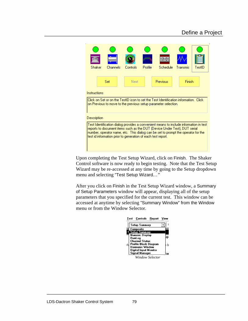
Define a Project
LDS-Dactron Shaker Control System 79
Upon completing the Test Setup Wizard, click on Finish. The Shaker Control software is now ready to begin testing. Note that the Test Setup Wizard may be re-accessed at any time by going to the Setup dropdown menu and selecting ”Test Setup Wizard…” After you click on Finish in the Test Setup Wizard window, a Summary of Setup Parameters window will appear, displaying all of the setup parameters that you specified for the current test. This window can be accessed at anytime by selecting ”Summary Window” from the Window menu or from the Window Selector.
Window Selector

Define a Project
LDS-Dactron Shaker Control System 80
Summary of Setup Parameters Table
Create a New Project To create a new Project, select New from the Project menu as shown below or use the new project icon from the Tool Bar icon. Hint – see Section 7, “Toolbar and Mouse Controls.”
Using the Project Menu to Create a New Project
After selecting New from the Project menu or the icon toolbar, the following New Project Selection window will appear. From this
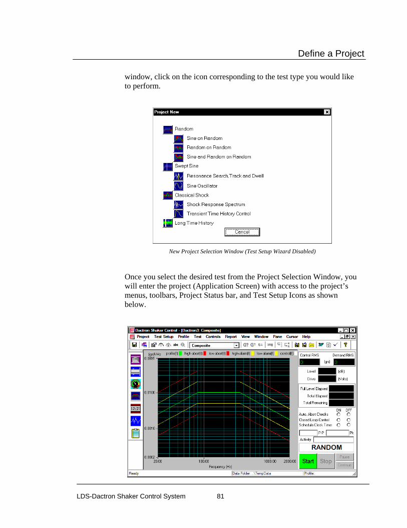
Define a Project
LDS-Dactron Shaker Control System 81
window, click on the icon corresponding to the test type you would like to perform.
New Project Selection Window (Test Setup Wizard Disabled)
Once you select the desired test from the Project Selection Window, you will enter the project (Application Screen) with access to the project’s menus, toolbars, Project Status bar, and Test Setup Icons as shown below.

Define a Project
LDS-Dactron Shaker Control System 82
New Project Application Screen
This section will briefly touch on the Project Status bar, Project Toolbar and Test Setup Icons however, please see Section 7 – Toolbar and Mouse Controls and Section 5 – Run a Project respectively for more detail concerning the these features.
Test Setup Icons The Test Setup Icons provide you with quick and convenient access to many of the commonly used setup parameters located in the Setup Menu such as Shaker Parameters and Test Profile. Altering or entering any test parameters using these icons is equivalent to using the Setup menu from the Project Toolbar.
Test Setup Icons
The following table describes the function of each icon.
Icon Access to:
• Shaker Shaker Parameters dialog.
• Channel Channel Parameters dialog
• Control Control Parameters dialog
• Profile Profile dialog
• Schedule Test Schedule dialog
• Transmis. Transmissibility dialog
• Test ID Test ID dialog

Define a Project
LDS-Dactron Shaker Control System 83
Project Status Bar
The Project Status Bar allows you to view two pieces of information concerning your test: Test Profile and the Data Folder location. This is useful when using the Profile Block Diagram to run multiple profiles and schedules in one continuous sequence.
Project Status Bar
Project Toolbar
The Project Toolbar is considered to be the “root” of the project. It contains ALL settings, functions, and preferences within its menus and icons. All other on-screen functions such as the Test Setup Icons or the Status Bar Controls are just easy to access shortcuts to these functions already in Project Toolbar. The general workflow of the Project Toolbar is from left to right. For example, you first define the setup parameters in the Test Setup menu, followed by defining your test profile in the Profile menu, and then ultimately ending your project by creating a test report from the Report menu.
As mentioned, this section describes the menu selections available for setting up a project. There are two main menus in the Project Toolbar that are used for setup:
• Test Setup • Profile
Moving to the right on the Project Toolbar, the next two menus selections deal with running a test and are explained in Section 5 – Run a Project.
• Test • Controls

Define a Project
LDS-Dactron Shaker Control System 84
In Section 6, “Creating Screens and Reports,” and Section 7, –“Toolbar and Mouse Controls,” the remaining menu selections on the Project Toolbar are explained. These menus are not required to create or directly run a Project, but they are essential part to operating the test and documenting it.
• Report • View • Window • Pane • Cursor • Help
When you first create a new project, it is untitled and labeled as “LDS-Dactron1” until you choose to save your project. Furthermore, all information from an untitled project is temporarily stored in the common Temp folder with the exception of saved data, which is permanently saved to the Temp folder. Therefore, it is highly recommended that you save your project before starting the test to avoid the loss of saved data.
Project Toolbar for an Untitled Project
Once a Project is saved, the Program Window header reflects the name you assigned to the Project and with the extension *.prj. For the example below, the name of the project is “ED Random”.
Project Toolbar for Project “ED Random”
Different project types (i.e. Random, Classical Shock, RSTD, etc.) can have different menus options and toolbar icons found in the Project Toolbar depending upon the project type you choose. There are four basic project groups: Random, Sine, Shock, and Long Time History.

Define a Project
LDS-Dactron Shaker Control System 85
Projects types in the same group share the same menu options and toolbar icons. The table below breaks each project type down by their respective groups.
Group Type Random • Random
• Random on Random (RoR) • Sine on Random (SoR) • Sine and Random on Random (SRoR)
Sine • Swept Sine • Resonance Search, Track, and Dwell (RSTD)• Sine Oscillator
Shock • Classical Shock • Shock Response Spectrum (SRS) • Time Transient History (TTH) Control
Long Time History
• Long Time History (LTH)
Project Types Sharing the Same Project Toolbar
Setting up a Project: Test & Profile Setup
Setting up a project uses two menus from the Project Toolbar: Test Setup and Profile. Because project types that are in different project groups have different menu options and toolbar icons, the description that follows is broken down as such:
• General Test Setup • Test & Profile Setup – Random and Mixed Mode • Test & Profile Setup – Swept Sine, RSTD, & Sine Oscillator • Test & Profile Setup – Classical Shock, SRS, & TTH • Test & Profile Setup – Long Time History (LTH)

Define a Project
LDS-Dactron Shaker Control System 86
Test Setup Menu (Random Test) Profile Menu (Random Test)

Define a Project
LDS-Dactron Shaker Control System 87
The Test Setup menu typically includes the following items:
Item Description • Engineering Units Used to define the preferred set of
measurement units. • Shaker Parameters Specifies the performance
limitations of the shaker table. • Channel Parameters Assignments, sensitivity
calibration, calibration values, and voltage range settings for input and output channels.
• Control Parameters Setup the control settings for the test
• Define Digital Input… Setup for digital input and output lines for external control and communication.
• Special Signals Math operations and definition of time characteristic histories.
• Signal Save Settings Setup signals to be automatically saved during the test.
• Test ID Setup Report Headers, and Test Information.
• Chamber Interface Setup
Setup Chamber Interface Parameters
• Waterfall Request Setup Event Waterfall plots
• Validate Parameters Checks all system parameters for conflicts and warnings
• Preferences Setup special parameters & features as well as file saving options.

Define a Project
LDS-Dactron Shaker Control System 88
The Profile menu typically includes the following items:
General Test Setup The Test Setup menu generally consists of the following setup dialogs. They are either identical or nearly the same for all project groups – Random, Sine or Shock.
• Engineering Units • Shaker Parameters • Channel Parameters • Control Parameters • Special Signals • Signal Save Settings • Transmissibility Signals • Test ID • Chamber Interface Setup • Waterfall Request • Validate Parameters • Preferences
- Miscellaneous - Email - Abort Action - Amplifier Control - Controls - Prompt Data Folder - Limit
Item Description
• Profile1 Definition and display of the test profile
• Schedule1 Pre-programs the test startup, the test, and any special test events
• Limiting Profile Defines profiles for non-control channels used for limiting or notching
• Block Diagram Sets up a multiple-profile test schedule

Define a Project
LDS-Dactron Shaker Control System 89
Engineering Units The Engineering Units page allows you to specify your preferred units. The units that first appear in the dialog are the project defaults.
Note: If the Engineering Units are changed, all setup parameters will reflect the chosen units. For example, if the units for Acceleration are changed from [gn] to [m/s2], then the channel sensitivity values in the Channel Parameters table will be converted from [mV/g] to [mV/m/s2].
Engineering Unit Selections for Sine
The Use global settings loads the global engineering units as defined in the Start-up Page or an individual project that already had this option enabled.
The possible selections using the drop-down menus are as follows:
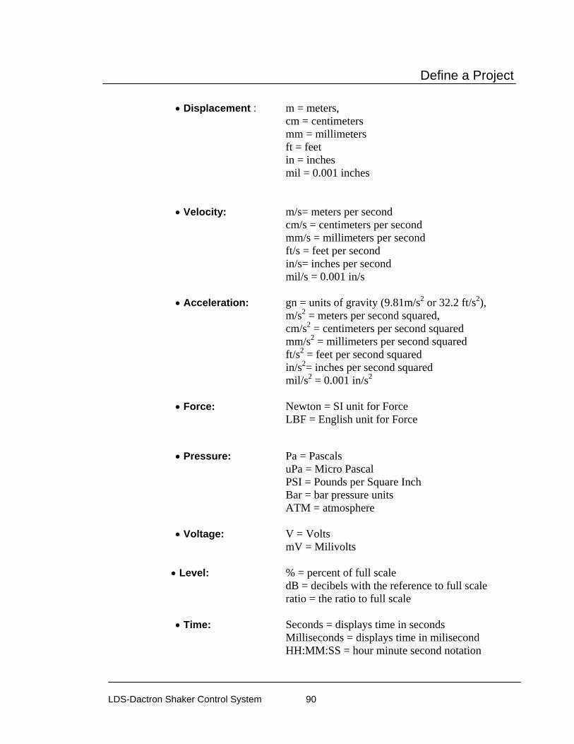
Define a Project
LDS-Dactron Shaker Control System 90
• Displacement : m = meters, cm = centimeters mm = millimeters ft = feet in = inches mil = 0.001 inches • Velocity: m/s= meters per second cm/s = centimeters per second mm/s = millimeters per second ft/s = feet per second in/s= inches per second mil/s = 0.001 in/s • Acceleration: gn = units of gravity (9.81m/s2 or 32.2 ft/s2), m/s2 = meters per second squared, cm/s2 = centimeters per second squared mm/s2 = millimeters per second squared ft/s2 = feet per second squared in/s2= inches per second squared mil/s2 = 0.001 in/s2 • Force: Newton = SI unit for Force LBF = English unit for Force • Pressure: Pa = Pascals uPa = Micro Pascal PSI = Pounds per Square Inch Bar = bar pressure units ATM = atmosphere • Voltage: V = Volts mV = Milivolts • Level: % = percent of full scale dB = decibels with the reference to full scale ratio = the ratio to full scale • Time: Seconds = displays time in seconds Milliseconds = displays time in milisecond HH:MM:SS = hour minute second notation

Define a Project
LDS-Dactron Shaker Control System 91
• User Defined: This is an engineering units label supplied by the user. For example, "ustrain" might be used to represent units of micro strain.
The following units are applicable only to Sine and RSTD • Log Sweep: Octave/Min or Decade/Min.
• Sine Displacement: Peak-to-Peak or Zero-to-Peak.
• Sine Display Duration: Time or Cycles.
Shaker Parameters The Shaker Parameters dialog allows you to set safety limits to protect the shaker system from being overstressed or damaged. These limits are typically the performance limits provided by the shaker manufacturer. All of test parameters in your project will be validated against these limits prior to and during testing. If a test parameter exceeds the shaker limits, test execution is prevented or the test is automatically aborted.
A database of LDS shaker models is included with the software. To choose the settings for an LDS shaker model, select it from the pull down menu. The current Shaker Settings are then displayed.

Define a Project
LDS-Dactron Shaker Control System 92
ShakerParaemtes SummaryListing
The Use global settings loads the global Shaker Parameters as defined in the Start-up Page or an individual project that already had this option enabled.
Shaker Library allows you to edit the current shaker parameters. This opens the Shaker Library dialog.

Define a Project
LDS-Dactron Shaker Control System 93
Shaker Library Dialog
All shaker settings are saved in a comma separated spreadsheet named ShakerLibrary.csv that is located in the LDS-Dactron\Shaker Control\Bin folder. When a new template is created or modified, the change is saved in this file. Select the shaker template to edit from the pull down menu. Then enter a name to save the settings under. If the same name is given in both text fields then the current settings will overwrite the old settings.
Enter the parameters in the various fields and click OK.
Apply saves the information without closing the dialog.
Import from parameter file allows the user to browse to a new tab delimited file for shaker parameters.
To enter limits in different engineering units (e.g., in meters instead of inches), go to the Engineering Units dialog box and change the units to correspond with your desired ones.
Enter the parameters for each type of test. Note parameters can very depending on the test type; Sine, Random or Shock.

Define a Project
LDS-Dactron Shaker Control System 94
Maximum Positive and Negative Displacement Limits set the maximum stroke permitted during a test.
Maximum Acceleration sets the maximum acceleration permitted during a test.
Maximum Force is the maximum force rating of the Shaker Model.
Minimum and Maximum Drive Frequency are used to limit the Drive signal frequency content (this prevents damage to the shaker and ensures that the sensor signals are meaningful).
Maximum Velocity sets the maximum velocity permitted during a test.
Maximum Drive Voltage is used to limit the Drive voltage (this prevents damage to the power amplifier).
Shaker Orientation is an optional text field used for documentation purposes only. The shaker position (e.g., vertical, horizontal, 45°, etc.) may be entered here.
Under Armature the shaker armature diameter and mass are specified. The Mass value is used in estimating the maximum force required by the test profile. The Diameter value is used only for general reference.
Channel Parameters The Channel Parameters dialog allows you to describe the sensors that are connected to the input and output channels of your system. This dialog contains two tables: Input and Output (Drive Signal).

Define a Project
LDS-Dactron Shaker Control System 95
Channel Parameters Table
Action Buttons
Fill Down copies the active entry field in any column to all of the entry fields below it in the same column.
Save and Recall allows you to save a set of Channel Parameters to a disk as a *.chl file or import a previously saved file. Channel Parameter Files can be imported into any Project File. This feature makes it possible to configure standard channel sets and to switch the Channel Parameter set when testing with a different sensor setup
Calibrate allows you to calibrate the sensitivity of a sensor using an external calibrator. This calibration feature will be described in further detail at the end this Channel Parameters section.
Channels
Channels are typically the external signals generated by sensors that come into your system for measurement and control processing.

Define a Project
LDS-Dactron Shaker Control System 96
Type allows you to define each input channel of your system as a Control, Monitor, Disable, or Response. All inputs selected as Control will be used in the control process as specified in the Control Parameters dialog. All inputs selected as Monitor are used for measurement purposes and can alter the control process when Automatic Notch Limiting is applied. Input channels selected as Response are used for measurement purposes only and do not affect the control process. Response channels are special in a way in that they can acquire non-kinematical signals – for example, pressure, force, and voltage. Channels defined as a Control or Monitor are limited to acceleration only. All channels selected as Disable will be ignored by the system.
MaxVolts is used to select the highest voltage amplitude expected from a sensor during the test (not the upper range of the sensor). The software will then use the full resolution in the range of ± MaxVolts. Keep in mind that most Random Tests will have most of their energy spikes below 3 Sigma (99.7% of the time) however occasionally a random noise spike will exceed 3 Sigma in which the MaxVolts range can be exceeded.
mv/(EU) is used to enter the sensitivity of the sensor on the input channel (mv = millivolts). The EU is the unit specified in Engineering Units

Define a Project
LDS-Dactron Shaker Control System 97
dialog. Refer to the manufacturer’s calibration specifications for the sensor and any amplifier/signal conditioner settings to determine this value. If a charge amplifier with a gain of 10 to 100 is used to condition the sensor, this must be taken into consideration for the input to the system.
Weighting is used only if “Weighted Average” is selected as the control strategy in the Control Parameters menu. If so, each normalized weight is applied to each control channel; the channels are then combined to create the control signal. The weighting function is applied to the amplitude domain, not the power domain. The weighting factor for an input channel is equal to the Weighting value for that input channel divided by the sum of all the Weighting values for the control channels.
Coupling is used to apply ICP®, AC or DC coupling to input channels. ICP provides a 4.7 mA current source (23 Vpeak open circuit) as signal conditioning for piezoelectronic accelerometers. AC coupling is a high-pass filter that removes the DC component of the input signal. DC coupling does not apply any filtering to the input signal. Note that the -3 dB filter knee for ICP is at 0.5 Hz and at 1.5 Hz for AC coupling. AC coupling is generally used for random and sine testing. Shock testing usually works best with DC coupling enabled.
Warning: LDS-Dactron recommends that the appropriate usage of AC and ICP coupling is as follows:
AC coupling - Use this method if frequencies of interest are all above 10 Hz (1% attenuation at 10 Hz)
ICP coupling - Use this method if frequencies of interest are all above 3.2 Hz (1% attenuation at 3.2 Hz)
For profiles containing frequency signals lower than what has been noted above, use an external signal conditioning unit with a very low AC coupling filter knee frequency. Note that the Shaker Control software does an offset detection at the start of the pre-test (prior to any drive signal being sent to the shaker) and these offsets are applied to the data measured during the test
Quantity is used to define the type of signal that will be measured by an input channel – such as Acceleration, Velocity, Pressure, etc. The Quantity should also match the type of sensor being used with that channel.
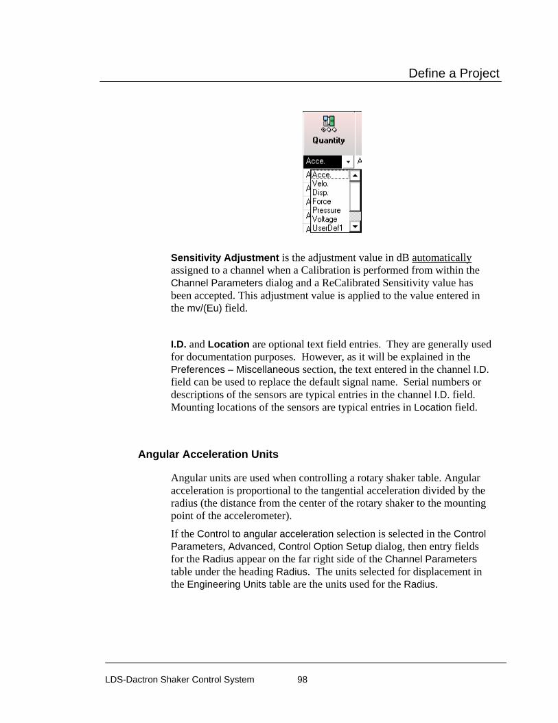
Define a Project
LDS-Dactron Shaker Control System 98
Sensitivity Adjustment is the adjustment value in dB automatically assigned to a channel when a Calibration is performed from within the Channel Parameters dialog and a ReCalibrated Sensitivity value has been accepted. This adjustment value is applied to the value entered in the mv/(Eu) field.
I.D. and Location are optional text field entries. They are generally used for documentation purposes. However, as it will be explained in the Preferences – Miscellaneous section, the text entered in the channel I.D. field can be used to replace the default signal name. Serial numbers or descriptions of the sensors are typical entries in the channel I.D. field. Mounting locations of the sensors are typical entries in Location field.
Angular Acceleration Units
Angular units are used when controlling a rotary shaker table. Angular acceleration is proportional to the tangential acceleration divided by the radius (the distance from the center of the rotary shaker to the mounting point of the accelerometer).
If the Control to angular acceleration selection is selected in the Control Parameters, Advanced, Control Option Setup dialog, then entry fields for the Radius appear on the far right side of the Channel Parameters table under the heading Radius. The units selected for displacement in the Engineering Units table are the units used for the Radius.
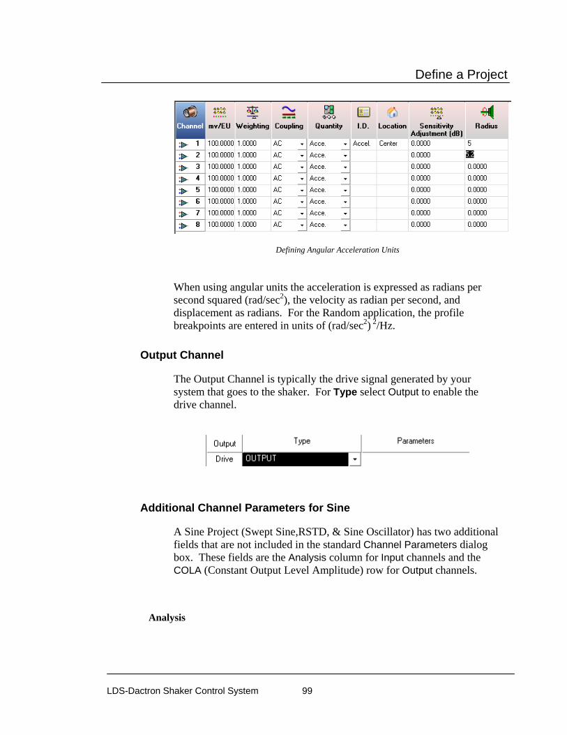
Define a Project
LDS-Dactron Shaker Control System 99
Defining Angular Acceleration Units
When using angular units the acceleration is expressed as radians per second squared (rad/sec2), the velocity as radian per second, and displacement as radians. For the Random application, the profile breakpoints are entered in units of (rad/sec2) 2/Hz.
Output Channel
The Output Channel is typically the drive signal generated by your system that goes to the shaker. For Type select Output to enable the drive channel.
Additional Channel Parameters for Sine
A Sine Project (Swept Sine,RSTD, & Sine Oscillator) has two additional fields that are not included in the standard Channel Parameters dialog box. These fields are the Analysis column for Input channels and the COLA (Constant Output Level Amplitude) row for Output channels.
Analysis

Define a Project
LDS-Dactron Shaker Control System 100
Analysis provides signal processing choices for Filter, Peak, Mean, RMS TRUE DC, and TRUE RMS level detection.
Sine Input Channel Analysis Options
Filter invokes digital tracking filter processing. The tracking filter is dynamic and has a center frequency that matches the drive frequency. The bandwidth of the tracking filter can be defined in the Control Parameters dialog as either a fixed frequency span or a variable span that changes as the drive frequency changes as shown. Noise and harmonic signals outside of the tracking filter bandwidth are suppressed, making this type of processing the generally preferred method of control.
Tracking Filter Bandwidth
The RMS, Mean, and Peak analysis methods use broadband filtering; this makes the control more susceptible to noise effects. These processing methods are preferable if the goal is to minimize the test excitation level when significant harmonic response signals are expected in the test frequency range.
Mean processing can be used to acquire DC level signals. However, any DC level signals must be disconnected during the initial ramp-up. This is because the system acquires ambient data (data with no excitation) just prior to ramp-up and uses the measured DC offset to null the signals measured during the test.
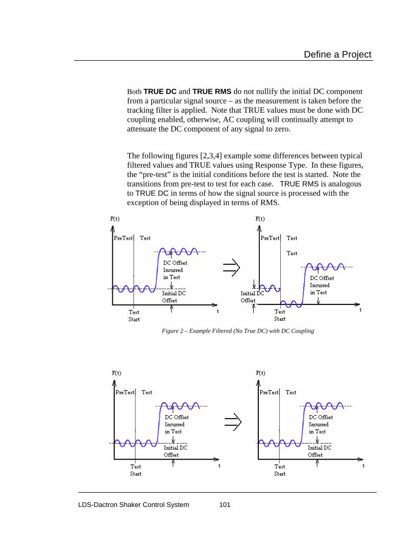
Define a Project
LDS-Dactron Shaker Control System 101
Both TRUE DC and TRUE RMS do not nullify the initial DC component from a particular signal source – as the measurement is taken before the tracking filter is applied. Note that TRUE values must be done with DC coupling enabled, otherwise, AC coupling will continually attempt to attenuate the DC component of any signal to zero.
The following figures [2,3,4] example some differences between typical filtered values and TRUE values using Response Type. In these figures, the “pre-test” is the initial conditions before the test is started. Note the transitions from pre-test to test for each case. TRUE RMS is analogous to TRUE DC in terms of how the signal source is processed with the exception of being displayed in terms of RMS.
Figure 2 – Example Filtered (No True DC) with DC Coupling
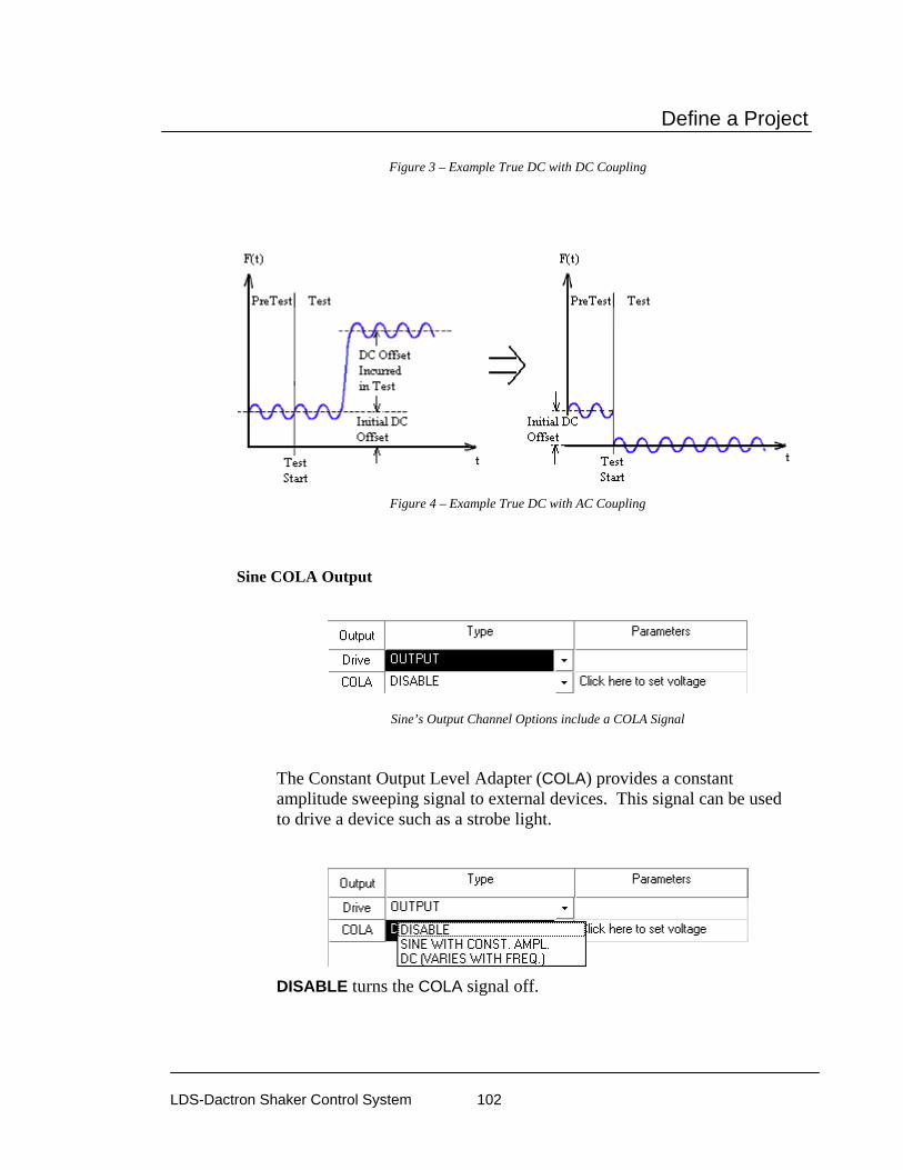
Define a Project
LDS-Dactron Shaker Control System 102
Figure 3 – Example True DC with DC Coupling
Figure 4 – Example True DC with AC Coupling
Sine COLA Output
Sine’s Output Channel Options include a COLA Signal
The Constant Output Level Adapter (COLA) provides a constant amplitude sweeping signal to external devices. This signal can be used to drive a device such as a strobe light.
DISABLE turns the COLA signal off.

Define a Project
LDS-Dactron Shaker Control System 103
SINE WITH CONSTANT AMPL turns the COLA signal on. Clicking on “Click here to set voltage” under Parameters allows you to set the peak voltage of the COLA signal.
DC (VARIES WITH FREQ.) provides a DC signal that is proportional to the current drive frequency. Clicking on “Click here to set voltage” opens a dialog box to define a DC proportional to frequency signal.
Left edge DC value __ (volts) corresponds to frequency __ Hz defines the relationship between the low frequency and low DC values. Right edge DC value __ (volts) corresponds to frequency __ Hz defines the relationship between the high frequency and high DC values. Linear-Linear Interpolation and Linear-Log Interpolation define the method used to calculate DC values as a function of the frequency. Linear-Linear causes a linear change in frequency to produce a linear change in the DC amplitude. For Linear-Log the DC amplitude changes linearly in proportion to a logarithmic change in the frequency.
Sensor Calibration
The sensitivity of a sensor may be calibrated using the Calibration feature located in the Channel Parameters dialog and an external calibrator that produces either an AC or DC signal. It should be noted that using an AC input signal for calibration only verifies the sensitivity for one frequency and does not guarantee calibration at other frequencies. Calibrating a sensor is done through the input channels

Define a Project
LDS-Dactron Shaker Control System 104
mV/(EU). Furthermore, only ONE channel may be calibrated at a time. This means that only one sensor can be excited by the input signal at any one time. To start the process, click on Calibrate in the Channel Parameters. This prompts the Calibrate Transducer Sensitivity dialog.
Calibrate Transducer Sensitivity Dialog
Use DC signal specifies that the input signal used for calibration will be a DC signal. Note that the Coupling in the Channel Parameters dialog should be set to DC for DC signal calibration.
Input Level defines the expected signal level.

Define a Project
LDS-Dactron Shaker Control System 105
Use AC signal specifies that the input signal used for calibration will be an AC signal. Note that the Coupling should be set to AC or ICP in the Channel Parameters dialog for AC signal calibration.
Input RMS Level defines the expected signal level.
Input Frequency is used to set the sampling frequency during the calibration. Enter the calibration signal frequency.
Auto accept if sensitivity deviation less than bypasses the accept/reject notification dialog and speeds up the calibration process.
After entering the above parameters, the calibration can be started. First disconnect all sensors from the calibrator and click on the Measure Noise button. This step is necessary so that the system can determine the noise level and identify the active channel during the calibration. After clicking on the Measure Noise button there is a short pause (10 seconds) while the system measures the noise level. When this period is complete, then the Start Calibration button will be enabled.
Start Calibration begins to scan the channels for an active calibration signal. When a calibration signal is detected, the system will compute the Re-Calibrated Sensitivity and Deviation (dB). If the “Auto-accept if sensitivity deviation less than” box is checked, the Re-Calibration value will be accepted and entered into the Calibration table. Otherwise the following dialog will be displayed.

Define a Project
LDS-Dactron Shaker Control System 106
Accept copies the Re-Calibrated Sensitivity and Deviation values to the Calibration table.
Calibration Table
Reject ignores the Re-Calibrated Sensitivity and Deviation values and starts the calibration process again by scanning the channels for an active calibration signal.
Stop Calibration ends the calibration process when the system is scanning the input channels for an active calibration signal.
Apply copies the Deviation values from the Calibration table to the Sensitivity Adjustment column in the Channel Parameters dialog. The Deviation values are used to modify the sensitivity values [mV/(EU)] in the Channel Parameters table in order to give the correct calibrated values.
Special Signals Special Signals are those signals that are part of the Project’s default signals or signals that have been recalled. They include signals that are created via Math Operations, Time Characteristics, or Import Remote Signal.
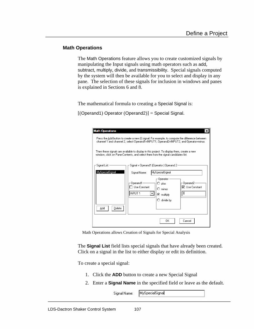
Define a Project
LDS-Dactron Shaker Control System 107
Math Operations
The Math Operations feature allows you to create customized signals by manipulating the Input signals using math operators such as add, subtract, multiply, divide, and transmissibility. Special signals computed by the system will then be available for you to select and display in any pane. The selection of these signals for inclusion in windows and panes is explained in Sections 6 and 8.
The mathematical formula to creating a Special Signal is:
[(Operand1) Operator (Operand2)] = Special Signal.
Math Operations allows Creation of Signals for Special Analysis
The Signal List field lists special signals that have already been created. Click on a signal in the list to either display or edit its definition. To create a special signal:
1. Click the ADD button to create a new Special Signal
2. Enter a Signal Name in the specified field or leave as the default.
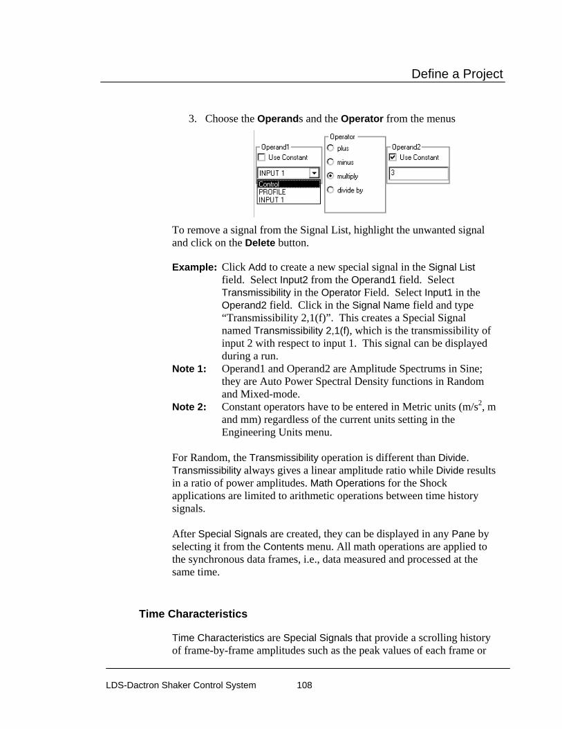
Define a Project
LDS-Dactron Shaker Control System 108
3. Choose the Operands and the Operator from the menus
To remove a signal from the Signal List, highlight the unwanted signal and click on the Delete button. Example: Click Add to create a new special signal in the Signal List
field. Select Input2 from the Operand1 field. Select Transmissibility in the Operator Field. Select Input1 in the Operand2 field. Click in the Signal Name field and type “Transmissibility 2,1(f)”. This creates a Special Signal named Transmissibility 2,1(f), which is the transmissibility of input 2 with respect to input 1. This signal can be displayed during a run.
Note 1: Operand1 and Operand2 are Amplitude Spectrums in Sine; they are Auto Power Spectral Density functions in Random and Mixed-mode.
Note 2: Constant operators have to be entered in Metric units (m/s2, m and mm) regardless of the current units setting in the Engineering Units menu.
For Random, the Transmissibility operation is different than Divide. Transmissibility always gives a linear amplitude ratio while Divide results in a ratio of power amplitudes. Math Operations for the Shock applications are limited to arithmetic operations between time history signals. After Special Signals are created, they can be displayed in any Pane by selecting it from the Contents menu. All math operations are applied to the synchronous data frames, i.e., data measured and processed at the same time.
Time Characteristics
Time Characteristics are Special Signals that provide a scrolling history of frame-by-frame amplitudes such as the peak values of each frame or

Define a Project
LDS-Dactron Shaker Control System 109
RMS value of each frame. These special displays are available in the Random, Mixed Mode and Long Time History applications.
Selections for Time Characteristic Signals
This setup allows you to measure the time characteristic history of each input channel with the following selections:
TIME CAPTURE is the time history record
RMS is the root mean square value
MAX is the maximum value
MIN is the minimum value
MEAN is a DC Measurement
PEAK-PEAK is the spread of the maximum and minimum values
PEAK is the greater of the maximum value and the absolute value of the minimum
The last five selections are the time characteristic estimation of each frame of data. This is a gap-free real-time calculation. The lengths of the signals are fixed at 1024 if they are time characteristics. If it is a

Define a Project
LDS-Dactron Shaker Control System 110
Time Capture Waveform, its size will be determined by settings in the Control Parameters (check the Data Point/Frame value listed). The figure below shows time histories of input channel 2 with Time Characteristics set as RMS. This gives a record of DC levels as a function of time into the test.
Time History Characteristic Plot of 8 Channels Measuring DC (RMS Estimation)
Note: If the Mean value is selected as the measurement, you need to
choose DC coupling in the corresponding channel setting. Otherwise, the DC component will be removed.
Caution: When measuring DC signals, use Response as the Type and
DC as the Coupling in the Channel Parameters dialog. Otherwise, any pre-test DC values will be subtracted from all measurements during the test giving an erroneous DC amplitude measurements.
Signal Limit
The Signal Limit aborts the test if the Hinverse function, or selected transmissibility or input channel spectrum, exceeds specified abort limits. Hinverse could change because of fatigue in the test article, breakdown or improper setup of the fixture and mounting or even degradation of the

Define a Project
LDS-Dactron Shaker Control System 111
shaker system. During a test the Hinverse Abort and Alarm tolerances may be overlaid on the Hinv display.
Check Limit Signal List shows all of the functions currently selected to use as limit signals. New signals may be selected by using the Available Signal List and the up arrow button. Signal Reference defines the abort reference signal. Active function uses function initialized and measured with each new test start and updated in real-time. Import function uses a previously measured function for the entire test. Use the Import button to select the previously measured function to use as the reference. Limits define the High/Low Alarm and Abort Limits in dB. Activate limit checking at this test level specifies the test level when the limit checking is applied. Limit checking will not apply when the test is at a level below the value entered in this field.
Import Remote Signal
The Import Remote Signal feature allows you to import signals from another application such as RT-Pro (LDS-Dactron Signal Analysis Software) using Real Time Data Exchange or RTDE. On prerequisite to importing a signal from an external application is that the signal must be enabled in that application. Upon selecting Import Remote Signal, the
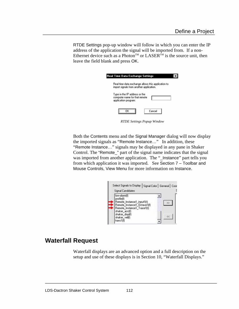
Define a Project
LDS-Dactron Shaker Control System 112
RTDE Settings pop-up window will follow in which you can enter the IP address of the application the signal will be imported from. If a non-Ethernet device such as a PhotonTM or LASERTM is the source unit, then leave the field blank and press OK.
RTDE Settings Popup Window
Both the Contents menu and the Signal Manager dialog will now display the imported signals as “Remote Instance…” In addition, these “Remote Instance…” signals may be displayed in any pane in Shaker Control. The “Remote_” part of the signal name indicates that the signal was imported from another application. The “_Instance” part tells you from which application it was imported. See Section 7 – Toolbar and Mouse Controls, View Menu for more information on Instance.
Waterfall Request Waterfall displays are an advanced option and a full description on the setup and use of these displays is in Section 10, “Waterfall Displays.”
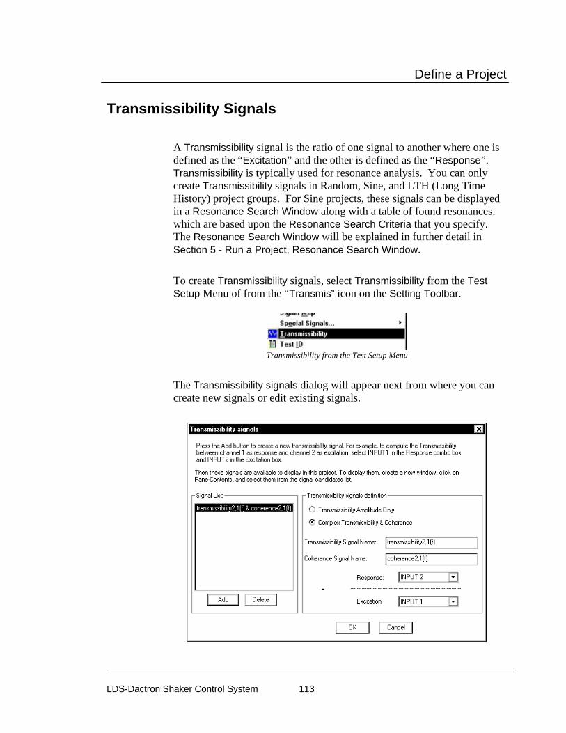
Define a Project
LDS-Dactron Shaker Control System 113
Transmissibility Signals A Transmissibility signal is the ratio of one signal to another where one is defined as the “Excitation” and the other is defined as the “Response”. Transmissibility is typically used for resonance analysis. You can only create Transmissibility signals in Random, Sine, and LTH (Long Time History) project groups. For Sine projects, these signals can be displayed in a Resonance Search Window along with a table of found resonances, which are based upon the Resonance Search Criteria that you specify. The Resonance Search Window will be explained in further detail in Section 5 - Run a Project, Resonance Search Window.
To create Transmissibility signals, select Transmissibility from the Test Setup Menu of from the “Transmis” icon on the Setting Toolbar.
Transmissibility from the Test Setup Menu
The Transmissibility signals dialog will appear next from where you can create new signals or edit existing signals.

Define a Project
LDS-Dactron Shaker Control System 114
The Signal List field lists the Transmissibility signals that have already been created. Click on a signal from the list to display or edit its definition. To create a special signal:
1. Click the ADD button to create a new Special Signal 2. Enter a Signal Name in the specified field or leave as the default. 3. Choose the Response and the Excitation from the drop down
menus. To remove a signal from the Signal List, highlight the unwanted signal and click on the Delete button.
Transmissibility signal definition defines the method used to compute the transmissibility signals.
Transmissibility Amplitude Only computes amplitude data only. The results are real signals.
Complex Transmissibility and Coherence computes the complex ratio of Response to Excitation. The results are complex signals and can be viewed in real-imaginary or magnitude-phase format. When this option is selected then coherence signals are automatically computed and can be displayed to indicate the quality of the tramissibility function.
In Sine projects only, the Transmissibility signals dialog has an additional button: Resonance Freq. Search Criteria.
When you click on this button, you enter the Define Resonance Criteria dialog as shown below. In this dialog, you can define the resonance criteria using the Q-factor and/or Amplitude ratio. You can then define how many resonances you wish to display in a Resonance Search Window based upon the resonance criteria.

Define a Project
LDS-Dactron Shaker Control System 115
Sine Resonance Search Criteria Dialog
Chamber Interface Setup
The Chamber Interface option enables the LDS-Dactron Shaker Control software to communicate with and control Thermal Chambers. Using the Chamber Interface Setup dialog box, the user is allowed to define conditions and actions for synchronized thermal and vibration testing that are based on Start, Stop, Abort, and Continue commands in the Shaker Control software. The user-defined condition is checked against commands made in the Shaker Control software; if the condition is met, then the user specified actions will be initiated on the thermal chamber and LDS-Dactron shaker controller. The actions that the user can define for the thermal chamber are setting the chamber set point temperature, turning on/off the chamber’s Digital Output channels and turning on/off the chamber. For the Shaker controller, actions such as writing a message to the runlog, making the PC beep, sending a test continue or stop command, or sending an email message can be defined.
Chamber Interface Setup
The Chamber Interface is accessible through the Test Setup menu for all types of projects (Random, Sine, Shock, etc) in the LDS-Dactron Shaker Control software. In the Test Setup menu select Chamber Interface Setup.
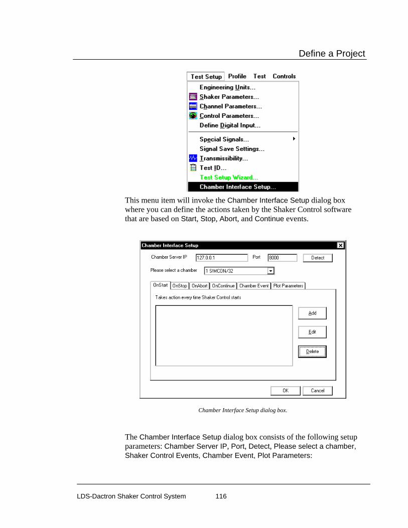
Define a Project
LDS-Dactron Shaker Control System 116
This menu item will invoke the Chamber Interface Setup dialog box where you can define the actions taken by the Shaker Control software that are based on Start, Stop, Abort, and Continue events.
Chamber Interface Setup dialog box.
The Chamber Interface Setup dialog box consists of the following setup parameters: Chamber Server IP, Port, Detect, Please select a chamber, Shaker Control Events, Chamber Event, Plot Parameters:

Define a Project
LDS-Dactron Shaker Control System 117
Chamber Server IP and Port define the IP address and TCP/IP Port that the Shaker Control software uses to communicate with and control the Thermal Chamber. The values in these fields are default values for the Thermal Chambers and should not be changed unless otherwise specified.
Please select a chamber allows you to select the available Thermal Chamber to use.
The Shaker Control Event tabs allow you to Add, Edit, and Delete actions taken by the Shaker Control software. The actions that can be taken by the Shaker Control software can occur during an OnStart, OnStop, OnAbort, OnContinue event; these actions will depend on the condition and actions defined in the interface. By clicking on the Add button in the Chamber Interface Setup dialog box, under any event tab, the condition and actions can be set in the Define condition and actions dialog box. You can also use the Edit button to edit any previously defined condition and action.
Chamber Interface Setup, Define conditions and actions dialog box.
The Define condition and actions dialog box consists of the Description, Chamber Name, Controlled Value, Condition, Actions by Chamber, and Actions by Shaker Controller fields: Description allows you to create a general description of the conditions

Define a Project
LDS-Dactron Shaker Control System 118
and actions you defined for the Shaker Controller command you selected in the Chamber Interface Setup dialog box. Chamber Name represents the name of the Thermal Chamber that the Chamber Interface is connected to. Controlled Value defines what parameter to use for thermal control. The options for this field are Temperature and Relative Humidity. Condition allows you to specify what type of condition to use to determine if an action by the Thermal Chamber or LDS-Dactron controller will be initiated. The types of conditions available are as follows:
Unconditional: no condition will be applied to determine if an action by the Chamber and/or LDS-Dactron controller will occur. Get Actual Value: if the Value (temperature or humidity) matches, exceeds, or is less than the value specified, then an action by the Chamber and/or LDS-Dactron Controller will occur. Get Digital Output: if the Index (or Chamber Digital Output channel) is detected as ON or OFF, then an action by the Chamber and/or LDS-Dactron Controller will occur. Get Digital Input: if the Index (or Chamber Digital Output channel) is detected as ON or OFF, then an action by the Chamber and/or LDS-Dactron Controller will occur. Get Error Status: used to detect errors on the Thermal Chamber, not commonly used by the Shaker Control software.
Actions by Chamber defines what actions are to be taken by the Thermal Chamber if the Condition is satisfied. You can specify to have the Thermal Chamber turned ON or OFF, you can set one of the Thermal Chamber’s Digital Output channel’s to ON or OFF, and you can specify the Set Point temperature in °C with a slope in °C /min.. Actions by Shaker Controller defines what actions are to be taken by the LDS-Dactron controller if the Condition is satisfied. You can specify that the LDS-Dactron Shaker Control software write a message to the runlog, make the PC beep, send a test continue or stop command, or send an Email message.

Define a Project
LDS-Dactron Shaker Control System 119
The Chamber Event tab allows you to define chamber events that can be identified by the Schedule using a Chamber Event Index number. For more details on the Chamber Event Index number reference Section 4 “Schedule for Random”.
The Plot Parameters tab allows you to add the Controlled Values (Temperature and Relative Humidity) to the Signal Candidates list so that they can be added to a new pane. You can also define Total recording duration in minutes and the number of Readout points per minute.
Plot Parameters tab in Chamber Interface Setup dialog box.
Example Chamber Interface Project
This section will describe the setup of a simple example project that shows the functionality and features of the Chamber Interface within the LDS-Dactron Shaker Control software. In this example, a Random project will be setup that interfaces with the Chamber Interface whose parameters will be set as listed below in Setup Parameters.
Setup Parameters
1) OnStart: Controlled Value is Temperature, the Condition is set to Get Actual Value, the Actions by Chamber will set the Set Point temperature to 80 °C only if the actual chamber temperature matches or exceeds a specified value of 72 °C, and the Actions by Shaker Controller is set to Write to runlog.
2) OnStop: Controlled Value is Temperature, the Condition is set to Unconditional, and the actions will remain the same as in OnStart except that the Set Point temperature will be changed to 0 °C.

Define a Project
LDS-Dactron Shaker Control System 120
Setup Chamber Interface Parameters
Assuming you have the LDS-Dactron Shaker Control software running and a Random project open, go to the Test Setup menu and select Chamber Interface Setup. This will invoke the Chamber Interface Setup dialog box as described in the Introduction. In this dialog box with the OnStart tab selected, click on Add. This will invoke the Define condition and actions dialog box. Setup the OnStart event as described in Setup Parameter 1 above at the beginning of this section. When finished click on OK. Repeat the steps to setup the OnStop event for Setup Parameter 2, where the conditions and actions will be the same as the OnStart event except that the Set Point temperature will be changed to 0 °C instead of 80 °C. Then click on OK. You should now have two events defined (1 event for OnStart and 1 event for OnStop). The figures below show the setup for the OnStart event. When finished, click on OK in the Chamber Interface Setup dialog box to return to the Random project.

Define a Project
LDS-Dactron Shaker Control System 121
Chamber Interface, Define condition and actions dialog box.
Start the Example Random/Thermal Project
Click on the Start button in the Control Panel. A Test ID dialog box will prompt you if you want to Proceed Test or Cancel Test. Click on Proceed Test to start the Random/Thermal test. Also, as an option, fill-in desired information and select desired settings in the Content, Usage, and Append Mode.
The Random/Thermal test will run as defined in the Schedule. Note: In this example, the Schedule is set to run for 5 minutes at 100% Level, Save All Panes, and Auto-Save Signals; this is the default setting for a New Random project. Go to the Window menu and select ChamberWatch Window to view the status of the Chamber Interface run-time parameters.

Define a Project
LDS-Dactron Shaker Control System 122
The Chamber Watch Window provides you with pertinent information related to the Thermal Chamber depending on what you selected as the Controlled Value (e.g. Temperature or Relative Humidity).
The Chamber Watch Window below shows the status of the Thermal Chamber during the scheduled test after the OnStart event. This shows that the current Actual Value is 20 °C, and the Set Point Value is 20 °C since the Thermal Chamber has not yet reached or exceeded the specified value of 72 °C.
Chamber Watch Window
The Setup Parameters also specified to write to the runlog during the OnStart and OnStop events. The Chamber Interface events for a Condition set to Unconditional, it will be listed as Chamber Value under Source and Unconditional under Description.

Define a Project
LDS-Dactron Shaker Control System 123
Preferences – Controls & Limit The Controls and Limit tabs give you options to certain control features. The options available in these tabs depend upon the Project Group (i.e. Sine, Random, etc) and will be discussed later on in this section with each group.
Preferences – Miscellaneous The Miscellaneous Tab in the Preferences dialog gives you options to miscellaneous project features. The options in this tab depend on the Project Group (i.e. Sine, Random, etc) but there are some common options common to all projects – more specifically the Use Channel ID label for signal name, Enable On Line Tips, Runlog entry time shown as clock time, and Enable DC Remove when display Velocity or Displacement options. The miscellaneous options that are specific to a particular Project Group will be discussed later on in this section with each group.
Enabling to Make setup parameters effective immediately causes the an immediate update of the setup parameters so that, for instance, newly activated input channels will appear in the display Contents dialog and Signal Manager dialog. Note that when using this mode any data displays from the last test will also be cleared once a change is made to the any setup parameter.
Use Channel ID label for signal names

Define a Project
LDS-Dactron Shaker Control System 124
The Use Channel ID label for signal names option allows you to use the name entered into the ID field in the Channel Parameters dialog as the signal Display Name as specified in the Signal Manager. The Display Name is the name that is displayed in panes, reports, and as the file name when a signal is saved.
User Specified ID for Input Channels in Channel Parameters
In the example above, Inputs 1-4 in the Channel Parameters dialog have ID’s specified. When the Use Channel ID label for signal names box is checked, the Display Name in the Signal Manager will become the ID label as shown the below.
Signal Manager with “Use Channel ID label for signal names” Enabled
Enable On Line Tips Enable On Line Tips shows pop-up text to guide the user in using various features such as cursor movement, saving signal confirmation, waveform
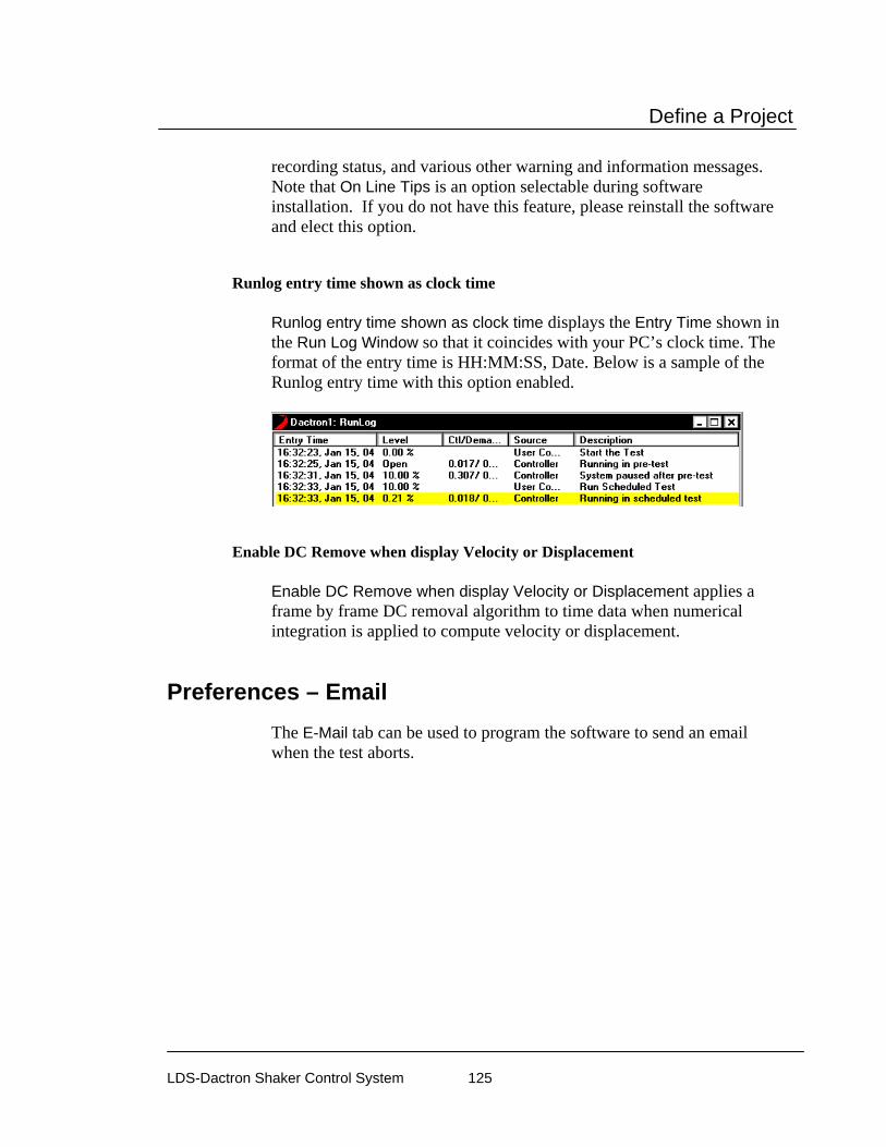
Define a Project
LDS-Dactron Shaker Control System 125
recording status, and various other warning and information messages. Note that On Line Tips is an option selectable during software installation. If you do not have this feature, please reinstall the software and elect this option.
Runlog entry time shown as clock time Runlog entry time shown as clock time displays the Entry Time shown in the Run Log Window so that it coincides with your PC’s clock time. The format of the entry time is HH:MM:SS, Date. Below is a sample of the Runlog entry time with this option enabled.
Enable DC Remove when display Velocity or Displacement Enable DC Remove when display Velocity or Displacement applies a frame by frame DC removal algorithm to time data when numerical integration is applied to compute velocity or displacement.
Preferences – Email The E-Mail tab can be used to program the software to send an email when the test aborts.

Define a Project
LDS-Dactron Shaker Control System 126
SMTP Server is required. The user must specify an outgoing mail server typically referred to as an SMTP server. Many companies have their own SMTP server. Contact your IT department for SMTP information. Other users will have to contact their ISP to get their SMTP server information.
Login is optional. Some SMTP servers may require the user to login. This feature is only available on Windows 2000 and above.
From address is required. The domain of the from address (part after the @) should match the domain of the SMTP server.
To address is required. Multiple addresses must be separated with a semi colon
Cc is optional. Multiple addresses must be separated with a semi colon
Subject is optional and allows the user to enter a text message that will be emailed when the test aborts.
Body is optional and allows the user to enter a text message that will be emailed when the test aborts.
Note that the Run Log text file will automatically be appended to the email as an attachment.

Define a Project
LDS-Dactron Shaker Control System 127
Preferences – Abort Action The Abort Action tab gives you options that the software can perform when the test aborts.
Auto Save Signal autosaves the signals selected under the Auto Save column in the Save Signal Manager to the test Run Folder when the test aborts.
Save All Panes saves snapshots of all panes currently displayed on the screen when the test aborts.
Make PC Beep causes your PC to emit a beep sound when the test aborts.
Send Email enables the Email function as setup in the Email tab of the Preferences dialog to send an email when the test aborts.
Preferences – Amplifier Control Amplifier Control serves as a link to the LDS System Controller software. This software allows the operator to setup, switch on/off, and monitor an LDS SPA-K amplifier from a PC. For more details on the LDS System Controller software, please refer to your LDS System Controller manual. Using the Amplifier Control option you can define what Actions are taken on the amplifier and what Messages are displayed within the Shaker Control software.

Define a Project
LDS-Dactron Shaker Control System 128
Actions allows you to enable/disable actions that can be taken on the amplifier when the test is started or stopped.
Turn amplifier ON when test is started allows the operator to switch the amplifier on within the Shaker Control software using a Start command. Turn amplifier OFF when test is stopped allows the operator to switch the amplifier off within the Shaker Control software using a Stop command.
Messages allows amplifier messages to be displayed within the Shaker Control software.
Warn before amplifier is started displays a warning message to the operator that amplifier will be started. Show Amplifier Error Messages displays any messages that appear within the amplifier’s LDS System Controller software.
Test & Profile Setup – Random & Mixed Mode
This section describes the Test Setup and Profile menus and dialog boxes for Random, Random on Random (RoR), Sine on Random (SoR), and Sine and Random on Random (SRoR) Projects.

Define a Project
LDS-Dactron Shaker Control System 129
Control Parameters for Random and Mixed-mode
For Random and Mixed-mode (RoR, SoR, and SRoR) projects, there are two pages in the Control Parameters dialog box: Pre-Test and Test. This menu is used to set test control methods and the pre-test process.
Test Page for Random Control Parameters
The processing technique for closed-loop control is defined in the Test page. The procedure used to start the test (i.e., begin drive signal output) is defined in the Pre-Test page.
Control Parameters for Random and Mixed-mode
Lines sets the number of spectral lines (frequency bands) to use in the control frequency bandwidth.

Define a Project
LDS-Dactron Shaker Control System 130
Delta Frequency allows a selection for the control PSD frequency increment. When this parameter is set the Lines are automatically reset to provide the correct deltaF value. Example: If Max Frequency = 2000 Hz and Delta Frequency = 5, then the frequency lines will be set to 400.
Max Frequency sets the upper limit of the control frequency bandwidth. Control processing is performed from zero Hz to Max Frequency Hz. Select the frequency range based on the profile requirements. When Auto is selected then the maximum frequency is automatically set to the maximum value in the profile table.
Control Strategy allows four different techniques to create the control signal using the input signals. Note that selections in the Channel Parameters menu are linked to the choice of Control Strategy.
Single Channel control strategy uses only one measurement for calculation of the Control PSD.
Weighted Average control strategy applies the weighting factor to every control input and then adds all the weighted signals together to produce the control signal. The factor for an input channel is equal to that input’s Weighting value squared, divided by the sum of the squares of the Weighting values for all the control inputs. If multiple channels are enabled in the Channel Parameter Setup, Weighted Average is the default selection.
Maximum control strategy checks each spectral line, in all the control inputs, and produces a composite control spectrum based on the largest values, at each spectral line, among the control inputs.
Minimum control strategy checks each spectral line, in all the control inputs, and produces a composite control spectrum based on the smallest values, at each spectral line, among the control inputs.
Line Abort counts the number of spectral lines exceeding the abort tolerances. The test automatically aborts if the defined number of lines in the Lines field or the percent of the total lines defined in the Percent field exceed the abort tolerances.
DOF, or Degrees Of Freedom sets the number of PSDs that will be averaged together to form the averaged Control Spectrum. In Random, the PSDs are averaged with both Linear Average and Exponential Average techniques (see Section 10, “Glossary”). This joint averaging method guarantees that (1) the PSD estimation is always un-biased and (2) every frame is included in the Control Spectrum calculation.

Define a Project
LDS-Dactron Shaker Control System 131
Drive Limit sets the maximum drive level (peak volts) that will be output to the amplifier. The settings here only apply to the scheduled test. For the pre-test process, there is another Drive Limit setup.
Sigma Clip is used to prevent extreme random noise spikes from entering the shaker system. This is useful when the desired test will be running close to the limits of the shaker. Sigma Clipping should be used with extreme care. A sigma level of 3 would be considered severe. At this setting, 0.3% of a true “random” signal would be above this level. Therefore, clipping at 3 Sigma would cause the Drive Signal to cease being “random”.
Caution!!! Clipping produces non-linear effects that can significantly reduce the system’s ability to control sharp resonances. This effect results from energy leaking across the test frequency range from the “square-wave” shape of the clipped peaks. The apparent noise floor will rise when a sigma clipping factor of 4 or less is used. In addition, signal energy out of the test bandwidth may be generated causing excitation of out-of-band resonances and poor control of resonances in the control frequency range under some conditions.
Advanced opens the Control Option Setup dialog. This includes three tabs: Non-Acceleration Control, Variable Resolution Control, and Control Loss Detection.
Non-Acceleration Control
Most shaker control applications use acceleration signals as the control signal. However, the software has an option that allows non-acceleration control signals.

Define a Project
LDS-Dactron Shaker Control System 132
Selecting an option for non-acceleration control.
Control in linear acceleration is the most common setting and allows control with acceleration signals.
Control in angular acceleration allows control of rotary shaker systems. When this option is enabled you must define the radius for each acceleration signal in the Channel Parameters dialog. All signals are then converted into angular acceleration.
Control in any non-acceleration allows the user to define the control quantity for the control signal from a pull down menu. This feature is commonly used for force, velocity, or displacement control. When this option is enabled, the shaker limits are not checked. It is critical that the user ensure that the profile will not exceed the shaker limits and cause damage to the system. When this option is enabled then the Channel Parameter and Profile are automatically changed to the specified control quantity.

Define a Project
LDS-Dactron Shaker Control System 133
If non-acceleration control is selected, then you must specify the type of sensor to be used for control.
Control in linear acceleration while allowing displacement or velocity measurement provides the facility to use a mixture of sensor types. For example, the low frequency end of the spectrum can be measured and controlled to a displacement sensor while the rest of the spectrum is controlled based on an acceleration sensor.

Define a Project
LDS-Dactron Shaker Control System 134
Selecting control with a transition from displacement to acceleration.
When using a combination of displacement and acceleration or velocity and acceleration sensors it is necessary to define a transition weighting curve. The transition curve defines the weighting for the displacement or velocity measurement relative to that for the acceleration measurement. In the example setup below the displacement sensor would control 100% at one Hertz, it would contribute 50% to the control at five Hertz, and it would not participate in the control above ten Hertz. The effect of the acceleration sensor would be just the reverse of the displacement sensor. That is, no control contribution at one Hertz, 50% at five Hertz and 100% at ten Hertz and above.
Defining the transition curve between displacement and acceleration control sensors.
For this control mode, the system cross-checks that the shaker limits are not exceeded by the demand of the reference profile.
Variable Resolution Control Tab
This dialog allows enabling of a special control algorithm that enhances the spectral resolution in the low frequency range of the control spectrum. A special filter technique in the low frequency band allows this algorithm to provide much higher low-frequency control accuracy. The resolution in the low-frequency range is enhanced by up to eight to one to give extremely accurate control across the entire test frequency range.

Define a Project
LDS-Dactron Shaker Control System 135
Random Advanced Control Window
Control Loss Detection
Control Loss Detection is an advanced feature that helps maintain control when the control signal changes quickly due to a resonance condition, or abort the system when the control signal is suddenly lost due to sensor failure.
Max Control Loss compares the control RMS to the full level profile RMS. When the control RMS differs from the full level profile RMS by the specified quantity, then the test aborts.
Max RMS Change Rate compares the RMS value of each control and/or monitor channel from frame to frame. If the level changes by the specified quantity between any two frames then the test aborts.
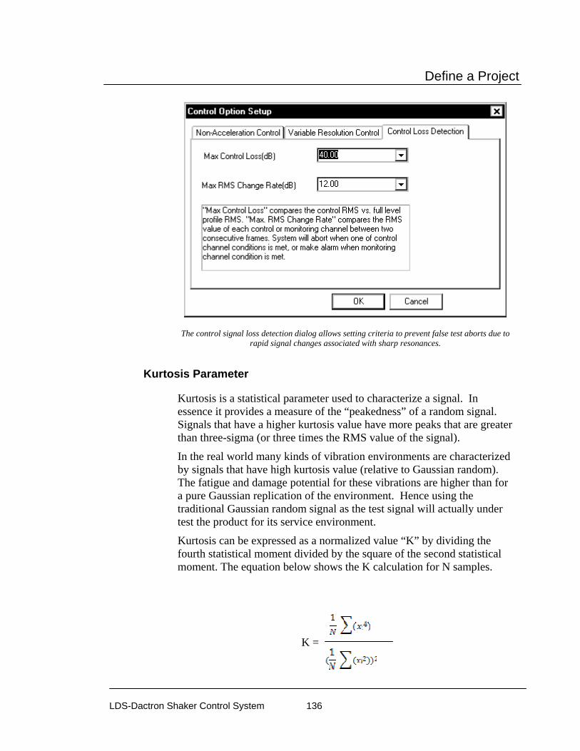
Define a Project
LDS-Dactron Shaker Control System 136
The control signal loss detection dialog allows setting criteria to prevent false test aborts due to rapid signal changes associated with sharp resonances.
Kurtosis Parameter
Kurtosis is a statistical parameter used to characterize a signal. In essence it provides a measure of the “peakedness” of a random signal. Signals that have a higher kurtosis value have more peaks that are greater than three-sigma (or three times the RMS value of the signal).
In the real world many kinds of vibration environments are characterized by signals that have high kurtosis value (relative to Gaussian random). The fatigue and damage potential for these vibrations are higher than for a pure Gaussian replication of the environment. Hence using the traditional Gaussian random signal as the test signal will actually under test the product for its service environment.
Kurtosis can be expressed as a normalized value “K” by dividing the fourth statistical moment divided by the square of the second statistical moment. The equation below shows the K calculation for N samples.
K =

Define a Project
LDS-Dactron Shaker Control System 137
For a Gaussian signal the K value is always 3 regardless of the PSD shape or RMS level of the test profile.
On the Kurtosis Parameter page you can set the K value. This value can be set anywhere from 3 to 7. When the value is set to 3 the test uses a Gaussian random signal. Higher K values produce signals with higher peak to RMS ratios than for a Gaussian signal. The PDF (Probability Density Function) plot provides a guide to the “peakedness” for a particular K setting. The Y axis represents the probability of occurrence and the X axis represents the peak to RMS ratio. This plot should be carefully considering when defining a test and the capabilities of the shaker system and amplifier should be checked against the peak to RMS demands of the test based on the kurtosis curves in the PDF plot.
Pre-Test Page for Random and Mixed-mode Control Parameters
The Pre-Test page defines the parameters for the initial equalization operations that occur prior to starting a full-level test. Method of Acquiring the Loop Frequency Response Function (FRF) section is used select one of the following schemes:

Define a Project
LDS-Dactron Shaker Control System 138
Measure during Pre-Test is the preferred method of achieving the FRF that will be used during the scheduled test.
Use Current Active Function and Skip Pre-Test is used only when the test has just been run successfully and nothing else has changed. Use this function only when extreme care has been taken to ensure that the test is being repeated with no changes at all from the last time it was run. A change of just a few hours of test-time is sometimes enough to have a significant effect on the running of a test.
Recall Function from Disk and Skip Pre-Test is used when you are absolutely sure that the FRF stored on disk is exactly the same as the current conditions. Use this selection only with extreme care.
If the number of Lines is changed, the Current Active Transfer Function and the Transfer Function Saved to Disk may still be valid for use because the control software interpolates to derive a new transfer function. A warning message will be shown if this happens. Be cautious when you take advantage of this Control Parameters feature because if you use an old transfer function with less resolution, the initial start-up process might be inappropriate.
If the Max Frequency setting is changed, the old transfer function cannot be used.

Define a Project
LDS-Dactron Shaker Control System 139
Pre-Test Parameters for Random and Mixed-mode
Initial Drive sets the drive voltage at which the signal amplitude will start. Use a very low setting (such as 0.005 volts) if you have no knowledge of the shaker system characteristics. For hydraulic shakers, set this value higher (such as 0.5 volts) to overcome the non-linearity of the hydraulic system.
Ramp-up Rate sets the speed with which the amplitude is going to increase. Take into consideration the response time of your entire shaker system for this setting. Avoid “Shocking” the system. A shock to the system would involve a ramp-up speed that exceeds the ability of the shaker system to respond to dynamic changes. Generally, Fast Ramp-up works well with linear systems such as electrodynamic shaker systems. For hydraulic shaker systems, which are very non-linear, the best choice is Slow Ramp-up.
Response Level Goal is the desired amplitude level that must be achieved for the test to pass the pre-test check. If this level is not achieved, the test will not run. This allows you to troubleshoot a potential problem before it affects the UUT or the shaker system.

Define a Project
LDS-Dactron Shaker Control System 140
Typical values for this selection range from 10% to 50%. Once the Response Level Goal is reached, the control system will retain the system transfer function and use it in the scheduled test.
Maximum Drive is the maximum limit (peak volts) of the drive channel during the pre-test.
Caution – Before every test verify that the Maximum Drive setting is a safe value (usually much less than one volt).
Skip Pre-Test Report and Start Scheduled Test provides the option to bypass the pre-test report, displayed after completion of the pre-test, and immediately start the Run Schedule. If this option is not selected (not checked), then the pre-test report is displayed and the operator must give a Proceed command to start the Run Schedule. Note that the normal pre-test safety check remain active regardless of the selection here. If there is an open-loop condition, if the maximum drive voltage is reached, or the desired response goal level is not achieved, then the pre-test will abort. Usually this selection is active (checked) when the Digital I/O and Project Sequence functions are used.
Preferences for Random and Mixed-mode
Controls Page for Random and Mixed-mode Preferences
The Controls page of the Preferences dialog box programs the rate of change of the drive signal during a test shutdown or during a level change in the pre-test or test. It also allows you to pre-program the incremental change to the drive signal using manual level control.

Define a Project
LDS-Dactron Shaker Control System 141
Control Preferences for Random and Mixed-mode
Abort Rate sets the rate of decrease for the drive signal after a manual or automatic abort. The larger the value, the faster the drive shutdown.
Caution: High abort rates (> 20 dB/sec) may cause a transient on the shaker with possible damage to the test article and/or the shaker.
Note 1: The abort process cannot be shorter than the acquisition time for one frame of data.
Note 2: The red hardware switch is the fastest way to initiate an abort. The hardware switch circuitry connects directly to the Drive controller hardware. Using the mouse to point and click on the screen STOP button will also initiate an abort but response is slower.
Enable resume from abort allows, if the box is checked, resuming a test after an abort. The full level elapsed time resumes at the time that the test aborted and the test runs until the remaining full level time

Define a Project
LDS-Dactron Shaker Control System 142
expires. When this option is enabled an Options button is shown that allows customizatiojn of the resume feature as show below.
Saving a project at the time a test is halted makes it possible to resume this test as part of resumed Project Sequence.
Abort on time out of Max. Drive (seconds) allows you to set a time in seconds for a maximum drive condition to exist before the system aborts the test. For example, it this time is set to 10 seconds then the maximum drive condition is ignored unless this condition exists over a period of 10 seconds or more.
Abort on time out of input clipped (seconds) allows you to set a time in seconds for the maximum time period that an input voltage overload condition will be tolerated. For example, a setting of 10 seconds will abort the test if the input overload does go away after a 10 second period.
Level Change Rate is used by the Time At Level EVENT item in the Schedule to increase or decrease the Demand Peak Acceleration (i.e., the desired test level) during testing. This parameter sets the test startup rate unless a series of low-level steps are programmed as events in the Schedule. It is also used by the Set Level, Increase Level, and Decrease Level commands.
The Increment for Changing Level is used during testing by manual commands for Increase Level and Decrease Level. These menu commands change the Demand RMS level.
Limit Page for Random and Mixed-mode Preferences
The Limit page applies only if Channel Limit Profiles are enabled. If you disable low-abort checking for the control spectrum, the limit channels will reduce excitation to a level that does not exceed the limit

Define a Project
LDS-Dactron Shaker Control System 143
profile. If this feature is not enabled, then the test may abort as a limit channel(s) causes the drive signal to be lowered.
Enabling Limit Channels for Random and Mixed-mode
Miscellaneous Page for Random and Mixed-mode Preferences
The Miscellaneous page has an option to Enable floating profile display. If selected, then the profile, abort and alarm lines are displayed at the current demand level. In other words, these lines float from low level to full level as the test demand level changes during startup.
Other important features included on the Miscellaneous page are as follows:
The Reset averaging when level changes causes the control PSD to be reset when a level change of more than 10% is made. It is useful to enable this control feature when using a servo-hydraulic shaker or if the test article has a marked non-linear response. By resetting the averaging as the level changes the random control loop is able to more quickly adjust for the a non-linear response in the test load and to control the test more accurately.
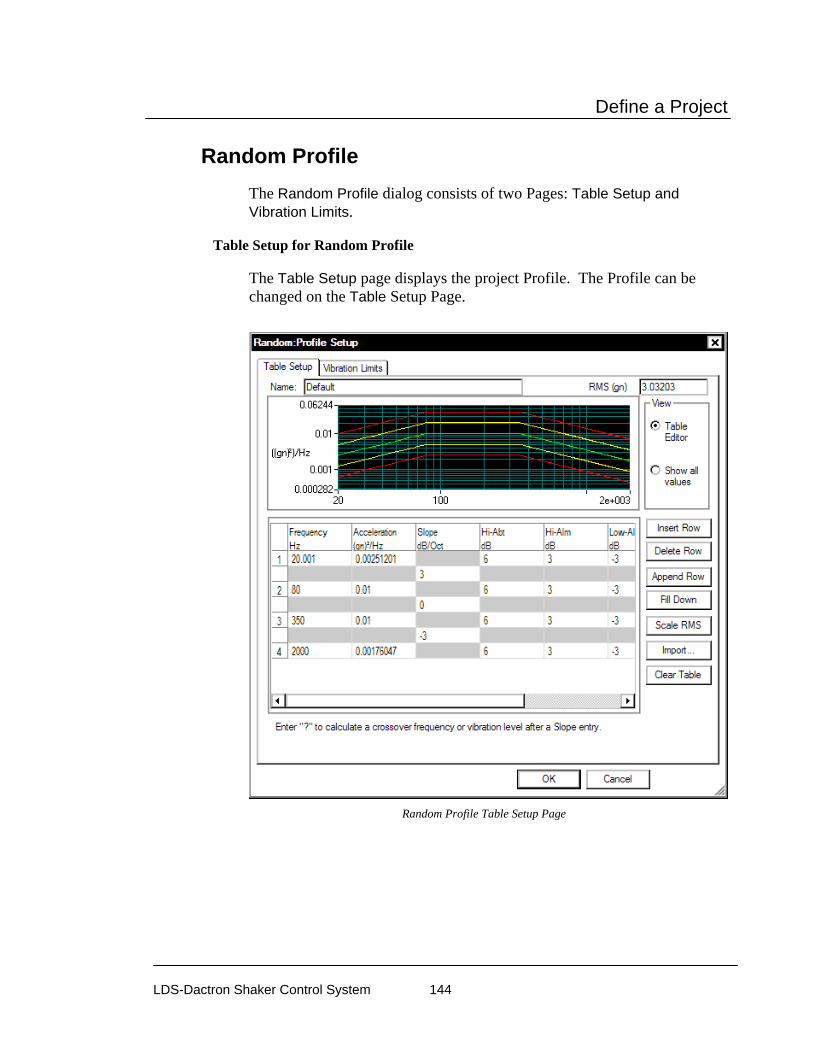
Define a Project
LDS-Dactron Shaker Control System 144
Random Profile The Random Profile dialog consists of two Pages: Table Setup and Vibration Limits.
Table Setup for Random Profile
The Table Setup page displays the project Profile. The Profile can be changed on the Table Setup Page.
Random Profile Table Setup Page

Define a Project
LDS-Dactron Shaker Control System 145
Table Setup Page for Random Profile
The Table Setup page allows you to enter the profile breakpoints and describe the resulting spectrum. The table functions like a spreadsheet. Each frequency, slope or level can be highlighted on the plot by clicking on the values in the table. In the figure below the 80 Hz breakpoint frequency, left slope and PSD Level is highlighted on the plot because the PSD Level of 0.1 is selected on the table. This feature helps understand and edit the profile.
Random Profile Table Setup
Each breakpoint is created by entering a Frequency value and an Acceleration PSD Level in each numbered row. Every numbered row is followed by an additional row that indicates the slope between each PSD

Define a Project
LDS-Dactron Shaker Control System 146
Level. When a table is defined only by PSD Levels then the slopes are automatically calculated.
The slope between breakpoints can be defined by entering a value in the Slope column below each numbered row.
If the crossover frequency or amplitude values is needed for an internal slope segment, enter the slope value and then place a “?” character in the Frequency or Acceleration entry field. The figure below shows an example that automatically computes the crossover frequency for a profile defined by a low frequency slope and a high frequency PSD level.
The Profile Setup window can be resized to help viewing and editing. The table can also be modified by right clicking on an entry and selecting from the pop-up menu.

Define a Project
LDS-Dactron Shaker Control System 147
Insert Row Before/After adds a row before or after the highlighted row.
Delete removes the highlighted row.
Copy copies the highlighted row to the clipboard.
Paste replaces the highlighted row with the clipboard contents.
Font Size changes the size of the font of all entries in the table with choices of small, medium or large.
The last four columns define the high-abort, high-alarm, low-alarm and low-abort limits. Together with the Abort-Ratio parameter defined in Control Parameters, these limits define alarm and abort conditions on a frequency-line-by-line basis. You can enter the low-alarm and low-abort values without a negative sign.
If there is an inconsistency between breakpoint segments, the system will display a crossover-frequency error message. If there are no breakpoint inconsistencies, the Profile is generated. At this time, the low-alarm and low-abort values will automatically be converted to negative values.
Name provides a text entry field for a description of the profile. This will later be displayed in various locations for your reference.
RMS (gn) shows the current RMS level of the profile that has been created. This field is a calculated field and is updated automatically when the profile is changed.
View (Table Editor or Show all values) is an either/or selection. In the Table Editor mode you can edit the profile. The Show all values mode shows all breakpoints, including those computed by the system. For some breakpoints, the table is defined by a combination of slope and

Define a Project
LDS-Dactron Shaker Control System 148
level entries. The system will automatically compute the intersection point (crossover frequency).
Insert Row inserts a duplicate of the active row (where the cursor is located). The new row is inserted above the active row.
Delete Row deletes the active row.
Append Row adds a duplicate of the last row at the bottom of the table.
Fill Down is a method for quickly filling in the same value in any of the alarm or abort columns.
Scale RMS invokes the Scale RMS dialog. This will allow you to change the overall RMS of the profile. Scaling the Overall RMS does not change the profile shape. The PSD amplitudes at all the frequencies are scaled up or down as required.
Clear Table removes all rows except for low and high breakpoints.
Import invokes the Import Profile for Random dialog. You can use this option to load a file containing a measured PSD and use this PSD as the target profile.
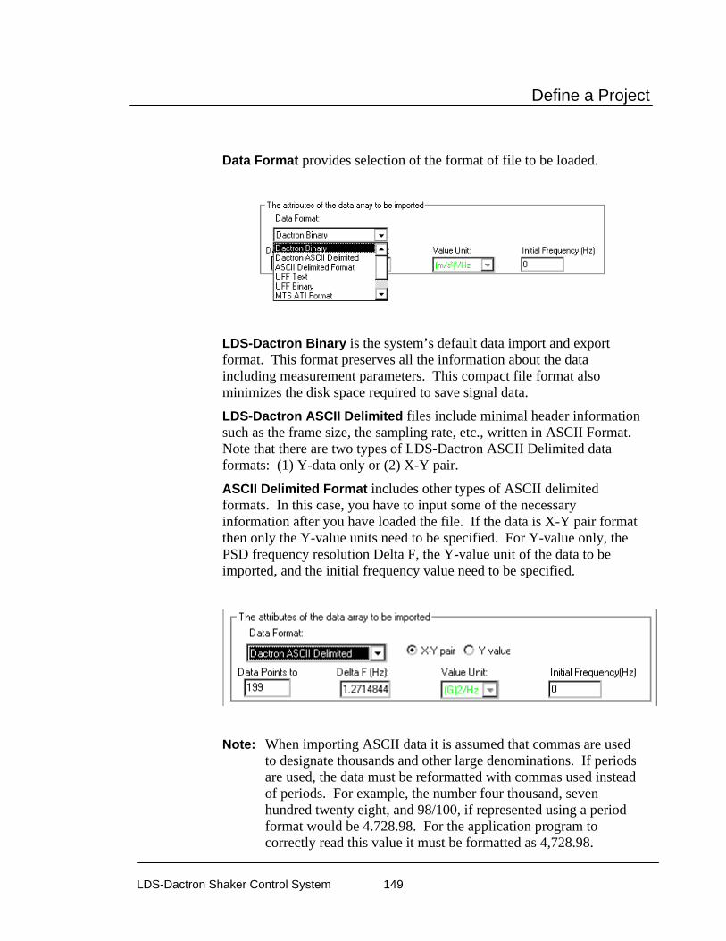
Define a Project
LDS-Dactron Shaker Control System 149
Data Format provides selection of the format of file to be loaded.
LDS-Dactron Binary is the system’s default data import and export format. This format preserves all the information about the data including measurement parameters. This compact file format also minimizes the disk space required to save signal data.
LDS-Dactron ASCII Delimited files include minimal header information such as the frame size, the sampling rate, etc., written in ASCII Format. Note that there are two types of LDS-Dactron ASCII Delimited data formats: (1) Y-data only or (2) X-Y pair.
ASCII Delimited Format includes other types of ASCII delimited formats. In this case, you have to input some of the necessary information after you have loaded the file. If the data is X-Y pair format then only the Y-value units need to be specified. For Y-value only, the PSD frequency resolution Delta F, the Y-value unit of the data to be imported, and the initial frequency value need to be specified.
Note: When importing ASCII data it is assumed that commas are used to designate thousands and other large denominations. If periods are used, the data must be reformatted with commas used instead of periods. For example, the number four thousand, seven hundred twenty eight, and 98/100, if represented using a period format would be 4.728.98. For the application program to correctly read this value it must be formatted as 4,728.98.

Define a Project
LDS-Dactron Shaker Control System 150
UFF Text and UFF Binary are popular industry formats. In Random, only auto-spectrum UFF signals can be recognized and imported.
Note: MTS ATI/AFU and RPCIII formats are only available on Windows 2000 operating system and are not available in others. Shaker Control is not able to recognize MTS ATI/AFU files set with a “Read-only” attribute as defined in the MTS library. Please ensure prior to attempting to recall MTS ATI/AFU files in Shaker Control that the "Read-only" attribute has been disabled for these files.
MTS ATI Format is a binary file used with IDEAS software.
MTS AFU Format is a binary file used with MTS Noise Path Analysis software.
Agilent SDF Format is a binary data file that is an open format used with many Agilent and HP devices. The structure is published and maintained by Agilent.
Refresh redraws the profile display at the top of the page.
RMS Limits Page for Random Profile
The first part of RMS Limits page lets you compare the shaker limits to the expected peak acceleration, velocity and Peak-Peak displacement of the profile.

Define a Project
LDS-Dactron Shaker Control System 151
Random Profile RMS Limits Page
Profile Expected Values are the “expected” values of the highest peaks that will be seen during the test. These values are calculated based on an assumption of a crest factor (peak to RMS ratio) of 3. The actual crest factor you will observe during testing depends on the linearity of the shaker system. Hydraulic shakers are very non-linear, and the assumption of a crest factor of 3 is generally good. However, electrodynamic shakers are generally very linear, and the actual crest factor may be closer to 4.
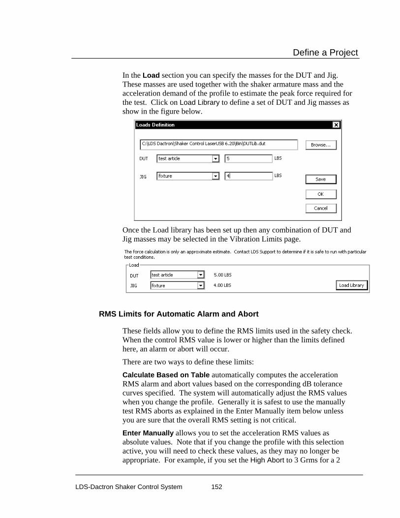
Define a Project
LDS-Dactron Shaker Control System 152
In the Load section you can specify the masses for the DUT and Jig. These masses are used together with the shaker armature mass and the acceleration demand of the profile to estimate the peak force required for the test. Click on Load Library to define a set of DUT and Jig masses as show in the figure below.
Once the Load library has been set up then any combination of DUT and Jig masses may be selected in the Vibration Limits page.
RMS Limits for Automatic Alarm and Abort
These fields allow you to define the RMS limits used in the safety check. When the control RMS value is lower or higher than the limits defined here, an alarm or abort will occur.
There are two ways to define these limits:
Calculate Based on Table automatically computes the acceleration RMS alarm and abort values based on the corresponding dB tolerance curves specified. The system will automatically adjust the RMS values when you change the profile. Generally it is safest to use the manually test RMS aborts as explained in the Enter Manually item below unless you are sure that the overall RMS setting is not critical.
Enter Manually allows you to set the acceleration RMS values as absolute values. Note that if you change the profile with this selection active, you will need to check these values, as they may no longer be appropriate. For example, if you set the High Abort to 3 Grms for a 2
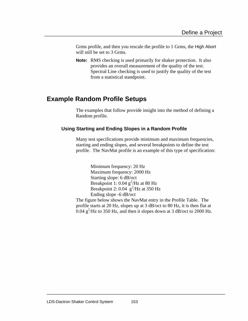
Define a Project
LDS-Dactron Shaker Control System 153
Grms profile, and then you rescale the profile to 1 Grms, the High Abort will still be set to 3 Grms.
Note: RMS checking is used primarily for shaker protection. It also provides an overall measurement of the quality of the test. Spectral Line checking is used to justify the quality of the test from a statistical standpoint.
Example Random Profile Setups The examples that follow provide insight into the method of defining a Random profile.
Using Starting and Ending Slopes in a Random Profile
Many test specifications provide minimum and maximum frequencies, starting and ending slopes, and several breakpoints to define the test profile. The NavMat profile is an example of this type of specification:
Minimum frequency: 20 Hz Maximum frequency: 2000 Hz Starting slope: 6 dB/oct Breakpoint 1: 0.04 g2/Hz at 80 Hz Breakpoint 2: 0.04 g2/Hz at 350 Hz Ending slope -6 dB/oct
The figure below shows the NavMat entry in the Profile Table. The profile starts at 20 Hz, slopes up at 3 dB/oct to 80 Hz, it is then flat at 0.04 g2/Hz to 350 Hz, and then it slopes down at 3 dB/oct to 2000 Hz.

Define a Project
LDS-Dactron Shaker Control System 154
Using Starting and Ending Slopes in a Random Profile.
Using Internal Breakpoints in a Random Profile
Some specifications require internal slopes. Random’s Profile Table has the capability for internal slope entry. The internal slope is defined by a breakpoint entry with a specified frequency and slope value. For example, the first figure below shows a profile with a constant 0.04 g2/Hz level, from 50 to 100 Hz, followed by a slope of -12 dB/oct. The Profile Table automatically calculates the PSD value for the 350 Hz breakpoint when a ? is entered in the Acceleration value. A full breakpoint table as calculated by the system is shown in the second figure.

Define a Project
LDS-Dactron Shaker Control System 155
Using an Internal Slope in a Random Profile
Full Breakpoint Table Showing Calculated Level at 350 Hz
Using Step Changes in a Random Profile
The figure below shows how to program in a Level Step Change in a Random Profile. No two breakpoints can have the same frequency so the

Define a Project
LDS-Dactron Shaker Control System 156
two breakpoints defining the low and high, or low and high, levels must have slightly different frequencies. Breakpoints 3 and 4, and 5 and 6, illustrate this point. This example also illustrates the use of non-symmetric tolerance bands. Starting at 201 Hz the abort and alarm tolerances spread. Between 500 and 2000 Hz different tolerance values are used for the high and low aborts and alarms.
Step Change in Random Profile
Mixed-mode Profiles A Mixed-mode Profile consists of a Broadband Random profile with a Narrowband profile “riding” on top of it. The Narrowband Profile can consist of random narrowband components, sine or “tone” components, or a combination of random narrowbands and tones. These mixed-mode profiles are referred to as Random on Random (RoR), Sine on Random (SoR), and Sine and Random on Random (SRoR).
RoR, SoR and SRoR all use a modified Random Profile menu.
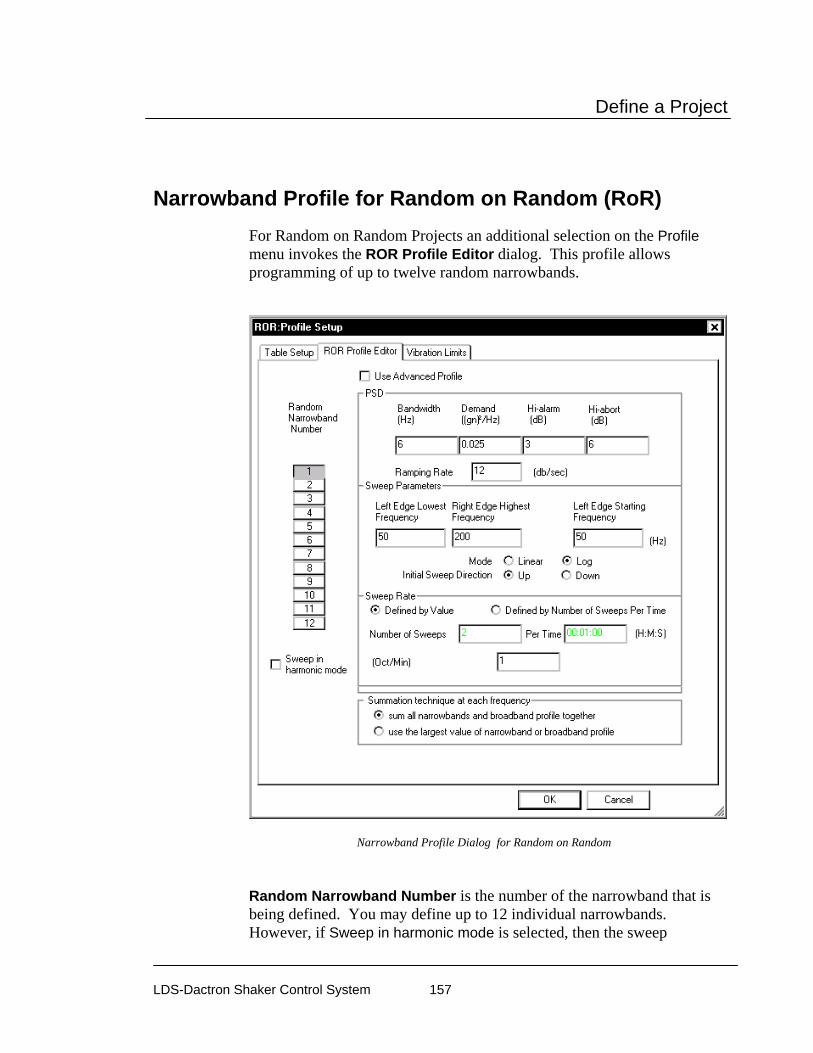
Define a Project
LDS-Dactron Shaker Control System 157
Narrowband Profile for Random on Random (RoR) For Random on Random Projects an additional selection on the Profile menu invokes the ROR Profile Editor dialog. This profile allows programming of up to twelve random narrowbands.
Narrowband Profile Dialog for Random on Random
Random Narrowband Number is the number of the narrowband that is being defined. You may define up to 12 individual narrowbands. However, if Sweep in harmonic mode is selected, then the sweep

Define a Project
LDS-Dactron Shaker Control System 158
parameters for tones 2 through 12 are automatically set based on the values used for tone 1.
Bandwidth is the frequency bandwidth of the narrowband random signal. The smallest bandwidth possible is that corresponding to the delta frequency value for the broadband profile (refer to the dF value listed in Control Parameters).
Demand is the amplitude (in units of Acceleration2/Hz) of the narrowband to be added to the Broadband Profile.
Left Edge Lowest Frequency marks the lowest frequency that this narrowband reaches when sweeping downwards.
Right Edge Highest Frequency is the highest frequency extreme that this narrowband reaches when sweeping upwards.
Left Edge Starting Frequency is the frequency at which the sweep will start.
Left Freq. Start Freq. Right Freq.
Bandwidth
Narrowband Sweep Range Definitions
Other controls on this page adjust the High Alarm and Abort limits (there are no low limits because this signal “rides” on the Random Profile). The Ramping Rate sets the speed that the narrowband amplitude will increase to its full level when the narrowband is turned on.
There a number of options for controlling the narrowband sweeps. These parameters include the Mode, linear or log, and the Initial Sweep Direction, either up or down. The Sweep Rate can be defined by specifying either the sweep rate in Hz/sec or the number of sweeps per a given time period.
The sum all narrowband and broadband profile together selection causes the narrowbands to add with the broadband random at every frequency. With this selection the narrowbands will add together if they cross over during a sweep.

Define a Project
LDS-Dactron Shaker Control System 159
The use the largest value of narrowband or broadband profile uses the maximum profile value, whether a narrowband or the broadband, at each frequency. With this selection the narrowbands will not add together if they cross over during a sweep. Rather the peak value during the cross over will be the value corresponding to the narrowband with the greatest profile value.
Narrowband Sweep Envelope
A special “envelope” signal allows you to display the narrowband sweep profiles. This signal can be overlaid on a display of the broadband random profile to give you an overall test profile display. The figure below shows an example display. See Section 6, “Creating Screens and Reports”, for more information on display setups.
Narrowband Sweep Envelope Overlaid on Broadband Profile
Vibration Limits for RoR
In the Vibration Limits page additional information is presented to account for the narrowband random or tone components of the profile.

Define a Project
LDS-Dactron Shaker Control System 160
Vibration Limits dialog page for the Mixed Mode Profile Setup
Narrowband RMS is the calculated square root of the sum of the squares of all the narrowband or tone components.
Overall RMS is the square root of the sum of the squares of the Broadband RMS and the Narrowband RMS.
Overall Expected Value is the “expected” peak value that will occur during a test. These values are calculated based on an assumption of a crest factor (peak to RMS ratio) of 3. The actual crest factor you will observe during testing depends on the linearity of the shaker system.

Define a Project
LDS-Dactron Shaker Control System 161
Hydraulic shakers are very non-linear, and the assumption of a crest factor of 3 is generally good. However, electrodynamic shakers are generally very linear, and the actual crest factor may be closer to 4

Define a Project
LDS-Dactron Shaker Control System 162
Sine Tones Profile for Sine on Random (SoR) For Sine on Random Projects, the SOR Profile Editor dialog allows programming of up to twelve sine tones.
Tone Profile Dialog for Sine on Random

Define a Project
LDS-Dactron Shaker Control System 163
Sweep in harmonic mode invokes a mode that automatically defines sweep frequencies and rates harmonically linked to the fundamental sine tone (the first tone).
Tone Number is the number of the sine tone that is being defined. You may define up to 12 individual tones. However, if Sweep in harmonic mode is selected, then the sweep parameters for tones 2 through 12 are automatically set based on the values used for tone 1.
All other parameters are associated with the tone number. Each sine tone has one page of parameters, which are defined as follows:
Amplitude (Peak) specifies the peak amplitude of the sine tone in this field. In Harmonic Mode, you may still independently specify the amplitude of all 12 tones.
The High Alarm and Abort limits set the upper tolerances during the tone sweep (there are no Low Limits because this signal “rides” on the Random Profile). The Ramping Rate sets the speed that the tone amplitude will increase to its full level when the tone is turned on.
The tone sweep can be tailored by setting the Sweep Parameters. These parameters include the sweep Mode, linear or log, and the Initial Sweep Direction, either up or down. The Sweep Rate is specified in linear mode as Hz/sec or Minutes/sweep, and either Oct/Min, Dec/Min or Minutes/sweep for log mode.
Burst Mode – This feature turns the tones on and off in an automatic cycle. The Time On and Time Off are independently set in seconds.
The Use Advanced Profile option allows entry of a sweep profile for each tone. Each profile table operates just like the Sine Profile Table. An example Tone Profile is shown below. See the “Profile for Sine and RSTD” Section, for details on the setup of a Sine Profile.
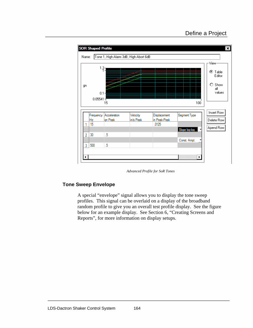
Define a Project
LDS-Dactron Shaker Control System 164
Advanced Profile for SoR Tones
Tone Sweep Envelope
A special “envelope” signal allows you to display the tone sweep profiles. This signal can be overlaid on a display of the broadband random profile to give you an overall test profile display. See the figure below for an example display. See Section 6, “Creating Screens and Reports”, for more information on display setups.

Define a Project
LDS-Dactron Shaker Control System 165
Tone Sweep Envelope Overlaid on Broadband Profile
Profile for Sine and Random on Random (SRoR) For Sine and Random on Random Projects, the Profile Setup dialog includes both the RoR Profile Editor and the SoR Editor pages. The setup for these two dialogs is as described above in descriptions of RoR and SoR.

Define a Project
LDS-Dactron Shaker Control System 166
Limiting Profile for Random and Mixed-mode To enable and define the limiting profile for an input channel, select Limiting Profile under the Profile menu.
To enable limiting control for a channel, select Notching Limit or Abort Limit for that channel. For a Notching Limit channel, if the input channel exceeds its limit during testing, the drive output (at that frequency) will be reduced (notched) until the input channel does not exceed its limit. For an Abort Limit setting, the test is automatically aborted if the spectrum of the Abort Limit channel exceeds its profile in any frequency range. To edit the limiting profile, highlight the field of that channel then click the Edit button.
Enabling a Limit Channel
The Profile Editor dialog box will be invoked:
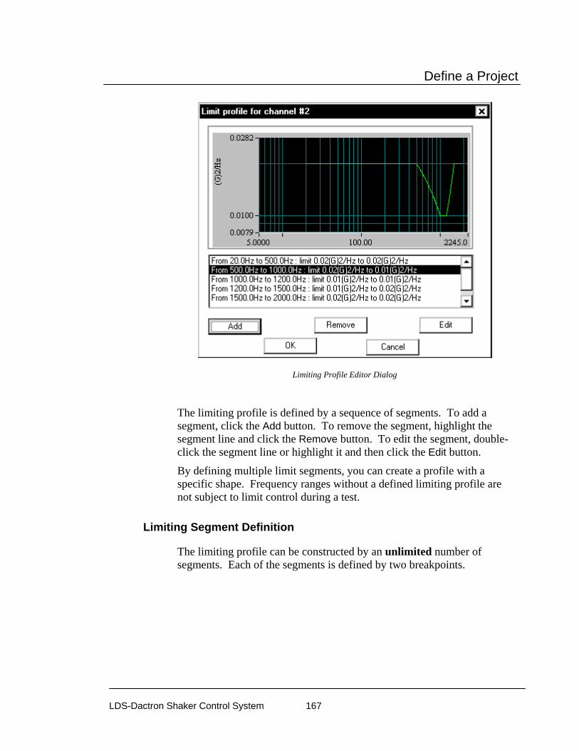
Define a Project
LDS-Dactron Shaker Control System 167
Limiting Profile Editor Dialog
The limiting profile is defined by a sequence of segments. To add a segment, click the Add button. To remove the segment, highlight the segment line and click the Remove button. To edit the segment, double-click the segment line or highlight it and then click the Edit button.
By defining multiple limit segments, you can create a profile with a specific shape. Frequency ranges without a defined limiting profile are not subject to limit control during a test.
Limiting Segment Definition
The limiting profile can be constructed by an unlimited number of segments. Each of the segments is defined by two breakpoints.

Define a Project
LDS-Dactron Shaker Control System 168
Defining a Limit Frequency Segment
A frequency and the corresponding PSD amplitude value define a breakpoint.
Schedule for Random The Schedule provides automatic programming for the following functions: test startup, test levels, test duration, enabling or disabling of abort checks, drive updating, and periodic saving of signal data. The selection list on the left side of the Schedule dialog adds entries for definition of the schedule.
To edit an entry, either double-click it, or highlight it and click the Edit Item button. You may also Delete an item in the list or Edit one that has already been entered.
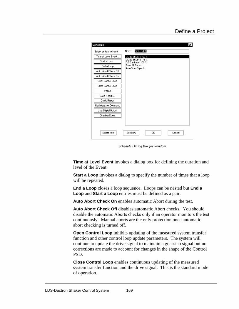
Define a Project
LDS-Dactron Shaker Control System 169
Schedule Dialog Box for Random
Time at Level Event invokes a dialog box for defining the duration and level of the Event.
Start a Loop invokes a dialog to specify the number of times that a loop will be repeated.
End a Loop closes a loop sequence. Loops can be nested but End a Loop and Start a Loop entries must be defined as a pair.
Auto Abort Check On enables automatic Abort during the test.
Auto Abort Check Off disables automatic Abort checks. You should disable the automatic Aborts checks only if an operator monitors the test continuously. Manual aborts are the only protection once automatic abort checking is turned off.
Open Control Loop inhibits updating of the measured system transfer function and other control loop update parameters. The system will continue to update the drive signal to maintain a guassian signal but no corrections are made to account for changes in the shape of the Control PSD.
Close Control Loop enables continuous updating of the measured system transfer function and the drive signal. This is the standard mode of operation.

Define a Project
LDS-Dactron Shaker Control System 170
Pause puts the system in a standby state (no drive signal output) for a pre-programmed period of time. The time period can be set for an indefinite time to allow remote test start via the Digital Input/Output function. In this case, the software waits for a Continue command from a specified Digital Input line and then executes the next item in the schedule.
Save Results invokes the following dialog box and lets you specify the signals to save automatically:
Save Results Dialog Box
Quick Report generates a test report within MS Word. This command can be used to automatically generate data plots or test reports at pre-set times or test events.
Net Integrator Command sends either a Start or Stop command to another application, such as RT-Pro, that is concurrently running.
User Digital Output invokes the following dialog box and lets you specify which of pins 2 – 9 on digital output port two to output a TTL signal.

Define a Project
LDS-Dactron Shaker Control System 171
Programming a TTL output signal via Digital I/O Port 2.
Chamber Event invokes the following dialog box and lets you create a new or view/edit a Chamber Interface Event.
Set a Chamber Event Dialog Box
Chamber Event Index provides an index number to reference a defined Chamber Event.
Select a chamber event below is a drop-down menu that allows you to select a defined Chamber Event to use in your Schedule.
New Event allows you to define a New Event without having to open the Chamber Event tab in the Chamber Interface Setup dialog. See the Section 4 “General Test Setup”, “Chamber Interface Setup” for more details on this dialog box.
View/Edit allows you to view or edit previously defined Chamber Events.

Define a Project
LDS-Dactron Shaker Control System 172
Example Random Schedule Setups The examples in this section illustrate how you can use Random’s Schedule feature to tailor your test runs.
Using the Schedule for Test Startup
You can use the Schedule to make the test startup gradual and smooth. This feature allows you to tune the test startup to best adapt to the characteristics of your shaker system and test article. Using the Schedule in this way prevents overshoots of full level due to insufficient time to fully equalize the load dynamics during the startup phase. The example Schedule below specifies a 3 dB level change every 10 seconds in going from -12 dB to 0 dB.
Random Schedule Setup for Gradual Test Startup
The For low level tests or tests where instrumentation line noise is a problem at low startup levels, automatic abort checks can be suppressed initially. This allows the test to equalize fully within tolerances at low level without spurious test shutdowns. Then the aborts can be activated at a higher level that is still significantly below full test level.

Define a Project
LDS-Dactron Shaker Control System 173
Random Schedule Setup to Program the Level for Automatic Abort Checking
Using the Schedule for Level Scheduling
Another use of the Schedule is for automatic level scheduling. In the example a five-minute full level test is followed by cycling of the level from 100% down to 75%, then 50%, then 25%, finally followed by a return to full level. Note that both the level, time at level, and number of cycles are programmable.
Random Schedule Setup for Automatic Level Scheduling
Using the Schedule to Automatically Save Results
You can program a Schedule to automatically save results. This includes saving Signals, Panes and test screen bitmaps. This example illustrates a Schedule setup for a test that runs for one hour and saves test results every minute. This Schedule uses a loop repeated sixty times to accomplish the automatic saves. Every loop includes a command to run at full level for one minute and then save all Panes, the specified Signals, and the application screen bitmap.

Define a Project
LDS-Dactron Shaker Control System 174
Random Schedule Setup to Automatically Save Results
Schedule for Mixed-mode When a RoR, SoR, or SRoR Project has been selected, an additional button(s) appears on the Schedule dialog box.
For RoR and SRoR, there is a button to activate the narrowbands for a selected schedule event.
Turning Narrowbands On/Off
Sine tones are activated for a selected schedule event by a button for SoR and SRoR:
Turning Sine Tones On/Off
These buttons invoke a dialog box that allows you to select the active narrowbands or tones. You can also turn the Broadband Random signal on or off.
Turn On/Off Bands Dialog

Define a Project
LDS-Dactron Shaker Control System 175
Test & Profile Setup – Swept Sine, RSTD, & Sine Oscillator
This Section describes the Test Setup and Profile menus and dialog boxes for Swept Sine, Resonance Search, Track and Dwell (RSTD), and Sine Oscillator Projects.
Control Parameters for Sine and RSTD For Sine and RSTD Projects there are three pages to the Control Parameters dialog box. These pages are the Test, Initial Ramp-up, and Transfer Functions.
Test Page for Sine and RSTD Control Parameters
The Test page sets general control parameters for the full-level test.
Control Parameters for Sine
Lines specifies the number of frequency resolution lines to be used for the frequency span (Max Frequency).

Define a Project
LDS-Dactron Shaker Control System 176
Control Strategy allows four different techniques to create the control signal using the input signals. Note that selections in the Channel Parameters Menu Item are linked to the choice of Control Strategy.
Single Channel control strategy takes the control and uses it as the control signal.
Weighted Average control strategy applies the factor to every control input and then adds all the weighted signals together to produce the control signal. The weighting factor for an input channel is equal to that input’s Weighting value squared, divided by the sum of the squares of the Weighting values for all the control inputs. If multiple channels are enabled in the Channel Parameter Setup, Weighted Average is the default selection.
Maximum control strategy checks each spectral point, in all the control inputs, and produces a composite control spectrum based on the largest values. Minimum control strategy checks each spectral point, in all the control inputs, and produces a composite control spectrum based on the smallest values.
Drive Limit is the maximum peak volts for the drive signal during the sine sweep.
Abort Latency defines the total number of seconds that the control signal may exceed the abort tolerances without a test shutdown. For example, if you define the Abort Latency as 0.1 seconds, then the test aborts only if the control signal exceeds the abort limit for over 0.1 of a second. If the time out abort tolerance exceeds 0.1 second, then the control system will abort the test. Sweep Type allows you to select either a linear or logarithmic sweep for the Sine signal. A numeric entry sets the sweep speed. For Linear Sweep Type, the sweep rate is defined in Hz/sec; for Log Sweep Type, the rate defined in Octave/min. Note that the sweep rate set here is the Default Sweep Rate. The default sweep rate can be over-ridden by an advanced setting in the Sweep Event entry of the Schedule.
Filter Type allows you to select the type of tracking filter and corresponding filter bandwidth specification. There are two types of filters: Proportional and Fixed. A Proportional filter changes bandwidth as the sine sweeps. A Fixed filter has a constant bandwidth regardless of the current sine frequency. See Section 10, “Glossary”, for detailed explanations of the terms Bandpass Filter and Bandwidth.
Compression Rate allows you to select the maximum rate of drive correction. See Section 10, “Glossary”, for additional discussion about

Define a Project
LDS-Dactron Shaker Control System 177
Compression Rate. The Use pre-defined table and Setup allows the user to define the compression rate as a function of frequency. The Setup button opens a dialog that defines the compression rate versus frequency.
Average specifies the method of averaging to use in the control loop -logarithmic or linear averaging. Generally logarithmic is the preferred method as it provides stable control characteristics. In some cases, such as when faced with a sharp, lightly damped resonance, linear averaging can improve the control accuracy. When Linear Average is selected then an Averaging Number must be specified.
Advanced opens the Control Option Setup dialog. This includes two tabs: Non-Acceleration Control and Control Loss Detection.
Non-Acceleration Control
Most shaker control applications use acceleration signals as the control signal. However, the software has an option that allows non-acceleration control signals.
Selecting an option for non-acceleration control.
Control in linear acceleration is the most common setting and allows control with acceleration signals.
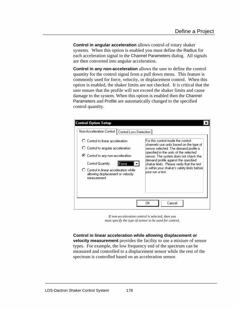
Define a Project
LDS-Dactron Shaker Control System 178
Control in angular acceleration allows control of rotary shaker systems. When this option is enabled you must define the Radius for each acceleration signal in the Channel Parameters dialog. All signals are then converted into angular acceleration.
Control in any non-acceleration allows the user to define the control quantity for the control signal from a pull down menu. This feature is commonly used for force, velocity, or displacement control. When this option is enabled, the shaker limits are not checked. It is critical that the user ensure that the profile will not exceed the shaker limits and cause damage to the system. When this option is enabled then the Channel Parameters and Profile are automatically changed to the specified control quantity.
If non-acceleration control is selected, then you must specify the type of sensor to be used for control.
Control in linear acceleration while allowing displacement or velocity measurement provides the facility to use a mixture of sensor types. For example, the low frequency end of the spectrum can be measured and controlled to a displacement sensor while the rest of the spectrum is controlled based on an acceleration sensor.

Define a Project
LDS-Dactron Shaker Control System 179
Selecting control with a transition from displacement to acceleration.
When using a combination of displacement and acceleration or velocity and acceleration sensors it is necessary to define a transition weighting curve. The Transition Curve defines the weighting for the displacement or velocity measurement relative to that for the acceleration measurement. In the example setup below the displacement sensor would control 100% at one Hertz, it would contribute 50% to the control at five Hertz, and it would not participate in the control above ten Hertz. The effect of the acceleration sensor would be just the reverse of the displacement sensor. That is, no control contribution at one Hertz, 50% at five Hertz and 100% at ten Hertz and above.

Define a Project
LDS-Dactron Shaker Control System 180
Defining the transition curve between displacement and acceleration control sensors.
For this control mode, the system cross-checks that the shaker limits are not exceeded by the demand of the reference profile.
Control Loss Detection
Control Loss Detection page provides advanced features that help to set the sensitivity of the controller abort detection to changes in the control signal(s). These settings can also prevent false test aborts due to the control signal changing quickly when sweeping through a very sharp anti-resonance.
The Enable control loss check when multi-channel control is used option enables the normal check for the loss of any of the control signals. When sweeping thorough a deep ant-resonance the controller will possibly detect a false control signal loss condition because the response of that accelerometer will be very small. If the normal control signal loss checks are disabled, by unchecking this selection, then it is possible to sweep through sharp anti-resonances without a false abort. Even with control signal loss detection disabled, the system will still abort the test if detects that all control signals appear to be lost.
Max Control Loss compares the control RMS to the full level profile RMS. When the control RMS differs from the full level profile RMS by the specified quantity, then the test aborts.
Max RMS Change Rate compares the RMS value of each control and/or monitor channel from frame to frame. If the level changes by the specified quantity between any two frames then the test aborts.

Define a Project
LDS-Dactron Shaker Control System 181
The control signal loss detection dialog allows setting criteria to prevent false test aborts due to rapid signal changes associated with sharp resonances.
Initial Ramp-up Page for Sine and RSTD Control Parameters
This page sets parameters for the initial equalization process and start-up of the Sine test.

Define a Project
LDS-Dactron Shaker Control System 182
Initial Ramp-up Dialog for Sine
Initial Drive sets the starting drive volts of the sine signal at the beginning of the test. This should be set to a low value initially to avoid “shocking” the system.
Maximum Drive during Ramp-up sets the highest drive voltage output value allowed during the ramp-up. If this limit is reached and the profile target level is not achieved, the ramp-up is aborted.
Ramp-up Rate sets the rate at which the signal amplitude will increase during the initial ramp-up prior to the start of the test. The best choice depends on the overall response of your shaker system. For electro-hydraulic shakers, or a low-frequency start-up (say lower than 10 Hz), use Slow Ramp-up.
After the initial ramp-up, the control system will immediately start the scheduled test without a pause.

Define a Project
LDS-Dactron Shaker Control System 183
Control Parameters for Resonance Search and Tracked Dwell (RSTD)
RSTD provides extensive resonance search capability with either frequency-locked dwell or phase-tracked dwell. The test status display provides on-line monitoring of resonance searches and a dwell status summary.
Detection of resonances during a search sweep is based on user specified criteria defined by a Search item in the Schedule. During a search sweep these criteria are applied to one of the real-time transmissibility function measurements to generate a list of detected resonances.
Control Parameters for Sine Oscillator For the Sine Oscillator Project there is one page to the Control Parameters dialog box, which is the Test page.
Test Page for Sine Oscillator Control Parameters
The Test page sets general control parameters for the full-level test.
Control Parameters for Sine Oscillator

Define a Project
LDS-Dactron Shaker Control System 184
Lines specifies the number of frequency resolution lines to be used for the frequency span (Max Frequency).
Drive Limit is the maximum peak volts for the drive signal during the sine sweep.
Filter Type allows you to select the type of tracking filter and corresponding filter bandwidth specification. There are two types of filters: Proportional and Fixed. A Proportional filter changes bandwidth as the sine sweeps. A Fixed filter has a constant bandwidth regardless of the current sine frequency. See Section 10, “Glossary”, for detailed explanations of the terms Bandpass Filter and Bandwidth.
Preferences for Sine, RSTD, and Sine Oscillator
Controls Page for Sine & RSTD Preferences
The Controls page of the Sine & RSTD Preferences dialog box provides for programming the rate of change of the drive signal during a test shutdown or during a level change in the course of a pre-test or test. It also allows you to pre-program the incremental change to the sine signal level and frequency using manual controls.
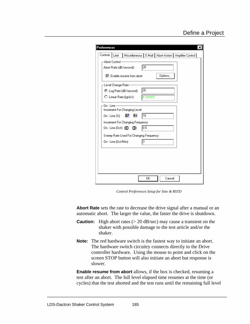
Define a Project
LDS-Dactron Shaker Control System 185
Control Preferences Setup for Sine & RSTD
Abort Rate sets the rate to decrease the drive signal after a manual or an automatic abort. The larger the value, the faster the drive is shutdown.
Caution: High abort rates (> 20 dB/sec) may cause a transient on the shaker with possible damage to the test article and/or the shaker.
Note: The red hardware switch is the fastest way to initiate an abort. The hardware switch circuitry connects directly to the Drive controller hardware. Using the mouse to point and click on the screen STOP button will also initiate an abort but response is slower.
Enable resume from abort allows, if the box is checked, resuming a test after an abort. The full level elapsed time resumes at the time (or cycles) that the test aborted and the test runs until the remaining full level

Define a Project
LDS-Dactron Shaker Control System 186
time (or cycles) expires. When this selection is enabled, an additional Option button is presented. The options available are show below.
Saving a project at the time a test is halted makes it possible to resume this test as part of resumed Project Sequence.
Level Change Rate is used by the Set Level, Increase Level, and Decrease Level to increase or decrease the Demand Peak (i.e., the desired test level) during testing.
Increment for Changing Level is used during testing by manual commands for Increase Level and Decrease Level. These menu commands change the Demand Peak level.
Increment for Changing Frequency is used to pre-program the change to drive frequency from the current value to a new value. Operating in fractional octaves, this parameter is used by the Increase Frequency and Decrease Frequency commands.
Sweep Rate Used for Changing Frequency is used to pre-program the rate for sweeping the drive frequency from the current value to a new value. It is active when you use the Increase Frequency and Decrease Frequency commands.
Controls Page for Sine Oscillator Preferences
The Controls page of the Sine Oscillator Preferences dialog box provides for setting of the following options: Frequency Change and Level Change Rate.

Define a Project
LDS-Dactron Shaker Control System 187
Control Preferences Setup for Sine Oscillator
Frequency Change allows you to specify how the Drive signal is adjusted when test frequency is changed. Change to specified frequency directly does not ramp down the Drive signal, but instead “jumps” to the specified frequency. The Ramp down before changing frequency setting ramps down the Drive signal before ramping back up to the specified frequency.
Level Change Rate is used by the Set Level, Increase Level, and Decrease Level to increase or decrease the Demand Peak (i.e., the desired test level) during testing.
Limits Page for Sine Preferences
The Limit page applies only if Channel Limit Profiles are enabled. Disabling low abort checking for the control spectrum allows the limit channels to reduce the excitation level enough to prevent exceeding the limit profile. If this feature is not enabled, the test may abort as a limit channel(s) causes the drive signal to be lowered.
Disabling Low-abort Checks with Limit Channels Enabled

Define a Project
LDS-Dactron Shaker Control System 188
Miscellaneous Page for Sine Preferences
The Miscellaneous page allows setting of the recording interval for control(t), frequency(t) and other time domain signals. A total of 2048 points can be recorded for each signal. Setting Time Resolution to 1.365 seconds (1365 milliseconds), for example, gives signals that record a total period of 46 minutes and 36 seconds (2796 seconds).
Setting the Time Resolution for Time Signal Records
The Only display the current sweep for the Control(f) and input(f) signals causes the display panes for these signals to be cleared on at the completion of each sweep. Then as the new sweep begins the signals are displayed as the sine frequency changes.
Profile for Sine and RSTD The Sine Profile contains two Pages: Table Setup, and Vibration Limits.
Table Setup Page for Sine and RSTD Profile
The Table Setup page allows you to enter the profile breakpoints and describe the resulting spectrum. The table functions like a spreadsheet.
Each frequency, acceleration, velocity or displacement level can be highlighted on the plot by clicking on the values in the table. In the figure below the 100 Hz breakpoint frequency is highlighted on the plot because it is selected on the table. This feature helps understand and edit the profile.
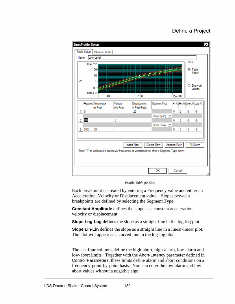
Define a Project
LDS-Dactron Shaker Control System 189
Profile Table for Sine
Each breakpoint is created by entering a Frequency value and either an Acceleration, Velocity or Displacement value. Slopes between breakpoints are defined by selecting the Segment Type.
Constant Amplitude defines the slope as a constant acceleration, velocity or displacement.
Slope Log-Log defines the slope as a straight line in the log-log plot.
Slope Lin-Lin defines the slope as a straight line in a linear-linear plot. The plot will appear as a curved line in the log-log plot.
The last four columns define the high-abort, high-alarm, low-alarm and low-abort limits. Together with the Abort-Latency parameter defined in Control Parameters, these limits define alarm and abort conditions on a frequency-point-by-point basis. You can enter the low-alarm and low-abort values without a negative sign.

Define a Project
LDS-Dactron Shaker Control System 190
If there is an inconsistency between breakpoint segments, the system will display a crossover-frequency error message and abort the profile generation process. If there are no breakpoint inconsistencies, the Profile is generated. At this time, the low-alarm and low-abort values will automatically be converted to negative values.
Vibration Limits Page for Sine Profile
The final page of the Sine Profile Dialog is the Limits page. It compares the shaker limits with the maximum values for the profile.
Profile Limits Page for Sine
In the Load section you can specify the masses for the DUT and Jig. These masses are used together with the shaker armature mass and the acceleration demand of the profile to estimate the peak force required for the test. Click on Load Library to define a set of DUT and Jig masses as show in the figure below.

Define a Project
LDS-Dactron Shaker Control System 191
Once the Load library has been set up then any combination of DUT and Jig masses may be selected in the Vibration Limits page.
Profile versus A,V,D Shaker Limits
You can set up a display to compare the profile against the shaker limits for acceleration, velocity, and displacement. The figure below shows displays of the profile plotted in the three dimensions – acceleration, velocity, and displacement – with the corresponding shaker limit values overlaid. Refer to Section 6, “Creating Screens and Reports”, for help on setting up display panes and special display formats.

Define a Project
LDS-Dactron Shaker Control System 192
Sine Profile Compared to Shaker Acceleration, Velocity and Displacement Limits
Example Sine Profile Setups
Crossover Frequency Calculation in a Sine Profile
Crossover frequencies are automatically calculated in the Profile Table. These frequencies are transition points between profile segments for different types of constant amplitude. For example, there is a change in slope in going from a constant displacement segment to a constant velocity segment. The crossover calculation determines the frequency at which the two types of slopes intersect. This ensures that the profile is smooth and without discontinuities. A continuous profile prevents any abrupt change in the acceleration level during the sine sweep.
Method 1 – Using the special ? entry To use this feature enter the first segment as the first row in the profile table, then enter in the next row the segment parameters with either the frequency or amplitude entered as a “?” character. Finally, the appropriate frequency or amplitude value is automatically calculated and displayed. Note that this method only works for the last row in the profile table.
In this example the first row defines a constant displacement and the second row a constant acceleration segment. Since the crossover
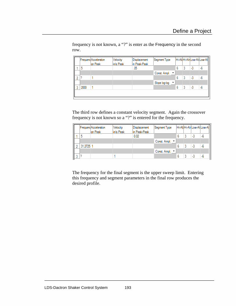
Define a Project
LDS-Dactron Shaker Control System 193
frequency is not known, a “?” is enter as the Frequency in the second row.
The third row defines a constant velocity segment. Again the crossover frequency is not known so a “?” is entered for the frequency.
The frequency for the final segment is the upper sweep limit. Entering this frequency and segment parameters in the final row produces the desired profile.
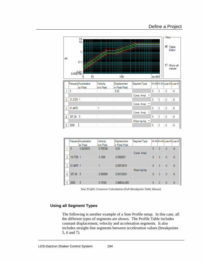
Define a Project
LDS-Dactron Shaker Control System 194
Sine Profile Crossover Calculation (Full Breakpoint Table Shown)
Using all Segment Types
The following is another example of a Sine Profile setup. In this case, all the different types of segments are shown. The Profile Table includes constant displacement, velocity and acceleration segments. It also includes straight-line segments between acceleration values (breakpoints 5, 6 and 7).
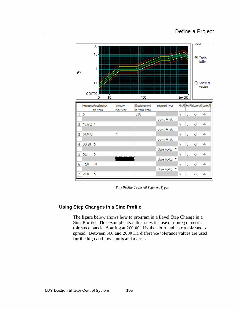
Define a Project
LDS-Dactron Shaker Control System 195
Sine Profile Using All Segment Types
Using Step Changes in a Sine Profile
The figure below shows how to program in a Level Step Change in a Sine Profile. This example also illustrates the use of non-symmetric tolerance bands. Starting at 200.001 Hz the abort and alarm tolerances spread. Between 500 and 2000 Hz difference tolerance values are used for the high and low aborts and alarms.

Define a Project
LDS-Dactron Shaker Control System 196
Step Change in a Sine Profile
Limiting Profile for Sine To enable and define the limiting profile for an input channel, select Limiting Profile under the Profile menu.
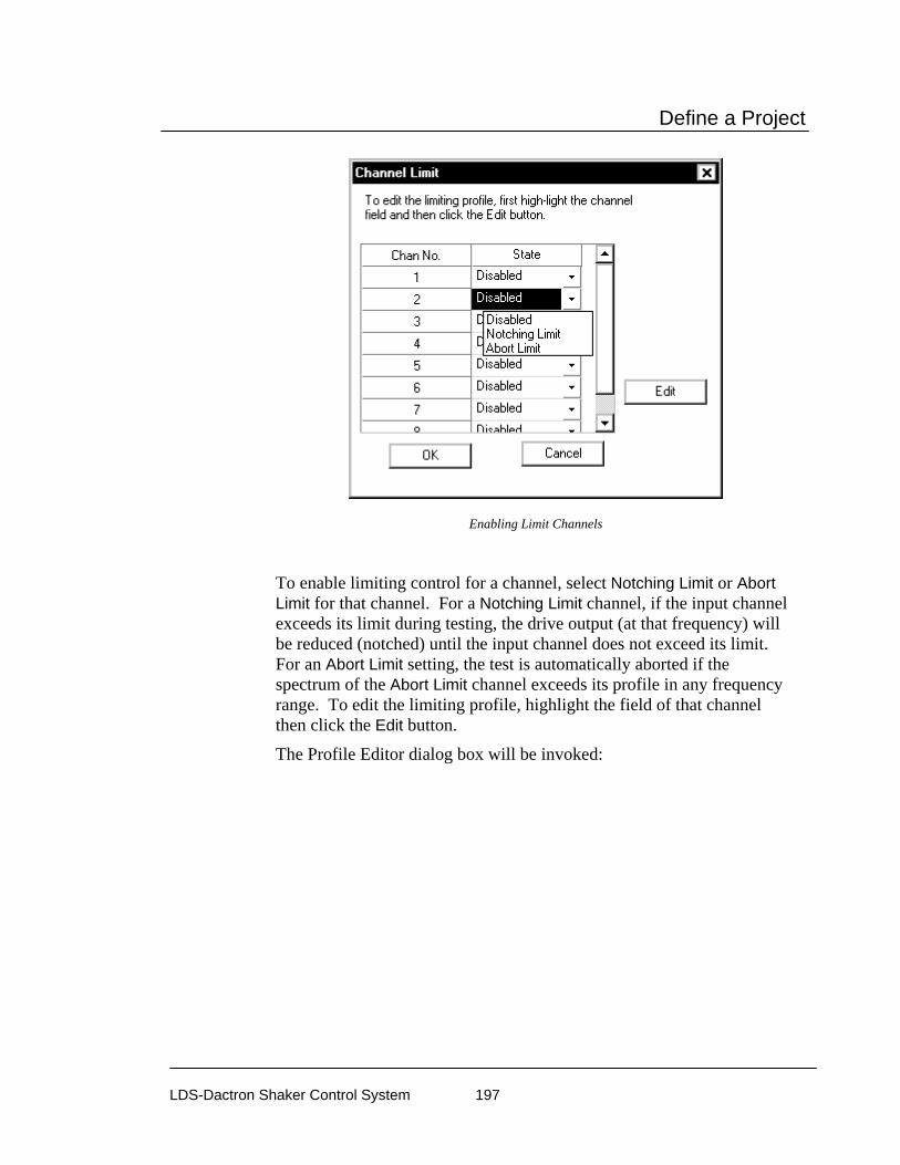
Define a Project
LDS-Dactron Shaker Control System 197
Enabling Limit Channels
To enable limiting control for a channel, select Notching Limit or Abort Limit for that channel. For a Notching Limit channel, if the input channel exceeds its limit during testing, the drive output (at that frequency) will be reduced (notched) until the input channel does not exceed its limit. For an Abort Limit setting, the test is automatically aborted if the spectrum of the Abort Limit channel exceeds its profile in any frequency range. To edit the limiting profile, highlight the field of that channel then click the Edit button.
The Profile Editor dialog box will be invoked:

Define a Project
LDS-Dactron Shaker Control System 198
Defining a Limiting Profile
The limiting profile is defined by a sequence of segments. To add a segment, click the Add button. To remove the segment, highlight the segment line and click the Remove button. To edit the segment, double-click the segment line or highlight it and then click the Edit button.
By defining multiple limit segments, you can define a profile with a specific shape. Frequency ranges without a defined limiting profile are not subject to limit control during a test.
Limiting Segment Definition
The limiting profile can be constructed by an unlimited number of segments. Each of the segments is defined by two breakpoints in the following dialog box:

Define a Project
LDS-Dactron Shaker Control System 199
Defining a Limiting Segment
A breakpoint is defined by a frequency and the corresponding Acceleration, Velocity, or Displacement value. When an acceleration, velocity or displacement value is entered, the system calculates the other two values.
Schedule for Swept Sine The Schedule provides automatic programming of the following: test startup, test levels, sweep ranges and durations, dwell tests, enabling or disabling of abort checks and drive updating, and periodic saving of signal data. The selection list on the left side of the Schedule dialog adds entries for definition of the Schedule.
To edit an entry, either double-click it, or highlight it and click Edit Item. You may also Delete an item in the list or Edit one that has already been entered.

Define a Project
LDS-Dactron Shaker Control System 200
Schedule Setup Dialog for Sine
Pretest for Sine Schedule
A Pretest schedule event is used to perform a check of the loop integrity, commonly referred to as a loop check, prior to attempting the initial ramp-up of the test. A frequency and level relative to the profile level are specified in the pretest setup table.
Pretest setup to do a loop check

Define a Project
LDS-Dactron Shaker Control System 201
After the pretest is complete a results table shows the noise levels and voltage levels expected at full level.
Sweep EVENT for Sine Schedule
Sweep EVENT determines the duration, frequency and speed of sine sweeps. When Sine makes the transition from one sweep event to another, it will usually ramp down first, then ramp up again at the next defined starting frequency. An exception is when the ending frequency of the previous sweep is identical to the starting frequency of current sweep. In this case, the Sine will continue to sweep without ramping down.
Sweep Event Parameters
In the Sweep EVENT dialog box, the following fields are set:
Sweep Duration Type: Time or Sweeps You may set sweep duration in terms of Time (hours:minutes:seconds) or in numbers of Sweeps. A complete sweep is defined as one sweep up or one sweep down.
A fractional number is a perfectly valid entry for the number of Sweeps. For example, if you want the sine to sweep over only one-half of the frequency range defined by the Lowest Frequency and the Highest Frequency values, set Sweeps to 0.50.

Define a Project
LDS-Dactron Shaker Control System 202
Advanced Sweep Rate Setting This field allows you to use a rate different rate than the Default Sweep Rate defined in the Control Parameters. To specify a special sweep rate for a schedule event, select Special Sweep Rate and enter the sweep rate in the edit box. Note that the Sweep Type (Linear or Logarithmic) setting in the Control Parameters determines the sweep rate units. If the Sweep Type is Linear, the unit is in either Hz/sec or Minute/Cycle. If the Sweep Type is Log, the sweep unit will be either Octave/Minute or Minute/Cycle.
Special Sweep Rate Selection
The Initial Sweep Direction defines the sweep direction after the Sine ramps up to the Starting Frequency. Lowest Frequency and Highest Frequency define the range of this Sweep Event.
The range of each sweep event should be within the valid range of the Profile and the Maximum Frequency defined in the Control Parameters. The figure following shows the relationship between these values:
SweepEvent
frequency range defined by the profile Maximum Frequency(defined in ControlParameters)
fLowest Freq Highest Freq
Sweep Range Definition

Define a Project
LDS-Dactron Shaker Control System 203
Integer Sweep Event for Schedule
An Integer Sweep Event provides for dwell and sweep events at integer frequencies. The event will start at the Start Frequency and dwell for the time specified in the Duration at each frequency field. After the dwell the frequency will sweep at the default rate to the next frequency defined by the Start Frequency plus the Interval Frequency and then dwell. This will continue until the sweep reaches the End Frequency.
Dwell Event for Schedule
A Dwell EVENT provides for fixed-frequency dwelling at a specified frequency or at the current frequency. The duration of the test can be specified in terms of time (hh:mm:ss) or cycle count.
Fixed Frequency Dwell Dialog
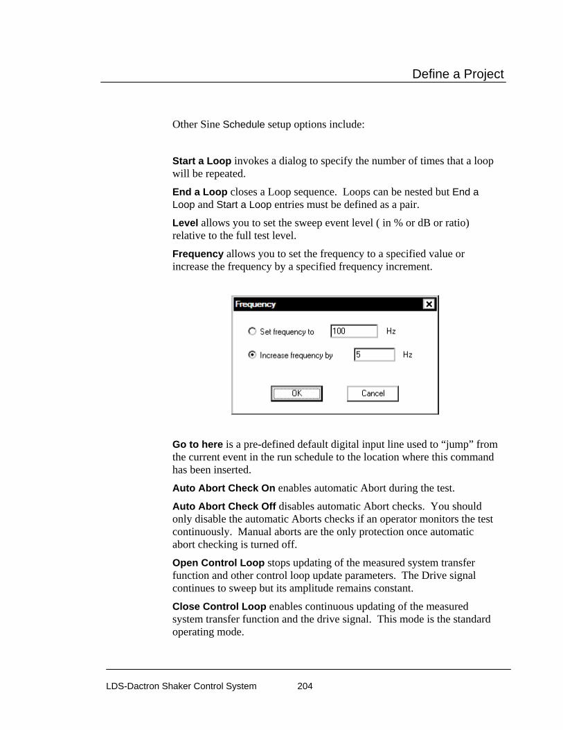
Define a Project
LDS-Dactron Shaker Control System 204
Other Sine Schedule setup options include:
Start a Loop invokes a dialog to specify the number of times that a loop will be repeated.
End a Loop closes a Loop sequence. Loops can be nested but End a Loop and Start a Loop entries must be defined as a pair.
Level allows you to set the sweep event level ( in % or dB or ratio) relative to the full test level.
Frequency allows you to set the frequency to a specified value or increase the frequency by a specified frequency increment.
Go to here is a pre-defined default digital input line used to “jump” from the current event in the run schedule to the location where this command has been inserted.
Auto Abort Check On enables automatic Abort during the test.
Auto Abort Check Off disables automatic Abort checks. You should only disable the automatic Aborts checks if an operator monitors the test continuously. Manual aborts are the only protection once automatic abort checking is turned off.
Open Control Loop stops updating of the measured system transfer function and other control loop update parameters. The Drive signal continues to sweep but its amplitude remains constant.
Close Control Loop enables continuous updating of the measured system transfer function and the drive signal. This mode is the standard operating mode.

Define a Project
LDS-Dactron Shaker Control System 205
Pause puts the system in a standby state (no drive signal output) for a pre-programmed period of time. The time period can be set for an indefinite time to allow remote test start via the Digital Input/Output function. In this case, the software waits for a Continue command from a specified Digital Input line and then executes the next item in the Schedule.
Save Results invokes the following dialog box and lets you specify the signals to save automatically:
Options for Saving Test Results
Quick Report generates a test report within MS Word. This command can be used to automatically generate data plots or test reports at pre-set times or test events.
Use Digital Output invokes the following dialog box and lets you specify which of pins 2 – 9 on digital output port two to output a TTL signal.

Define a Project
LDS-Dactron Shaker Control System 206
Programming a TTL output signal via Digital I/O Port 2.
Net Integrator Command sends either a Start or Stop command to another application, such as RT-Pro, that is concurrently running.
Chamber Event invokes the following dialog box and lets you create a new or view/edit a Chamber Interface Event. See Section 4 “Schedule for Random” for more details on this dialog box.
Set a Chamber Event Dialog Box
Example Sine Schedule Setups The following examples show example Sine Schedule setups used to automatically vary the sweep rate, to have a sweep automatically followed by fixed-frequency dwells, and to automatically save test results.

Define a Project
LDS-Dactron Shaker Control System 207
Using the Schedule to Automatically Vary the Sweep Rate
For this test the Default Sweep Rate is set as 1 Oct/min in the Control Parameters menu. An event is entered in the Schedule as “Sweep from 10 Hz to 100 Hz” at the Special Sweep Rate of 0.5 Oct/min. As the sine signal sweeps through the frequency range of 10 to 100 Hz, it will use a rate of 0.5 Oct/min. For all other frequency ranges of the test, the sine signal sweeps at the default rate of 1 Oct/min.
Sine Schedule Setup for Variable Sweep Rate
Using the Schedule for Automatic Sweep and Dwells
Another use of the Schedule is to program a single sweep test followed by a series of fixed-frequency dwells. In the example a single sweep from 5 to 2000 Hz is followed by dwells at 100, 500 and 1200 Hz. Both the frequency and duration can be specified for each dwell.
Sine Schedule Setup for Automatic Sweep and Dwells
Using the Schedule to Automatically Save Results
You can program a Schedule to automatically save results. This includes saving Signals, Panes and test screen bitmaps. The example illustrates a Schedule setup for a test with 200 sweeps and the results for every sweep automatically saved. This Schedule uses a loop repeated 200 times to accomplish the automatic saves. Every loop includes a command to sweep from 5 to 2000Hz, save results, and then sweep from 2000 to 5 Hz and save results.
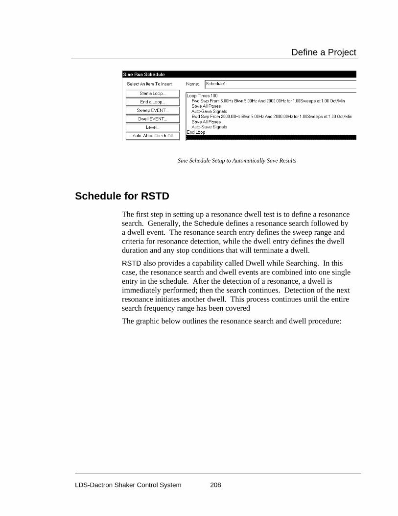
Define a Project
LDS-Dactron Shaker Control System 208
Sine Schedule Setup to Automatically Save Results
Schedule for RSTD The first step in setting up a resonance dwell test is to define a resonance search. Generally, the Schedule defines a resonance search followed by a dwell event. The resonance search entry defines the sweep range and criteria for resonance detection, while the dwell entry defines the dwell duration and any stop conditions that will terminate a dwell.
RSTD also provides a capability called Dwell while Searching. In this case, the resonance search and dwell events are combined into one single entry in the schedule. After the detection of a resonance, a dwell is immediately performed; then the search continues. Detection of the next resonance initiates another dwell. This process continues until the entire search frequency range has been covered
The graphic below outlines the resonance search and dwell procedure:
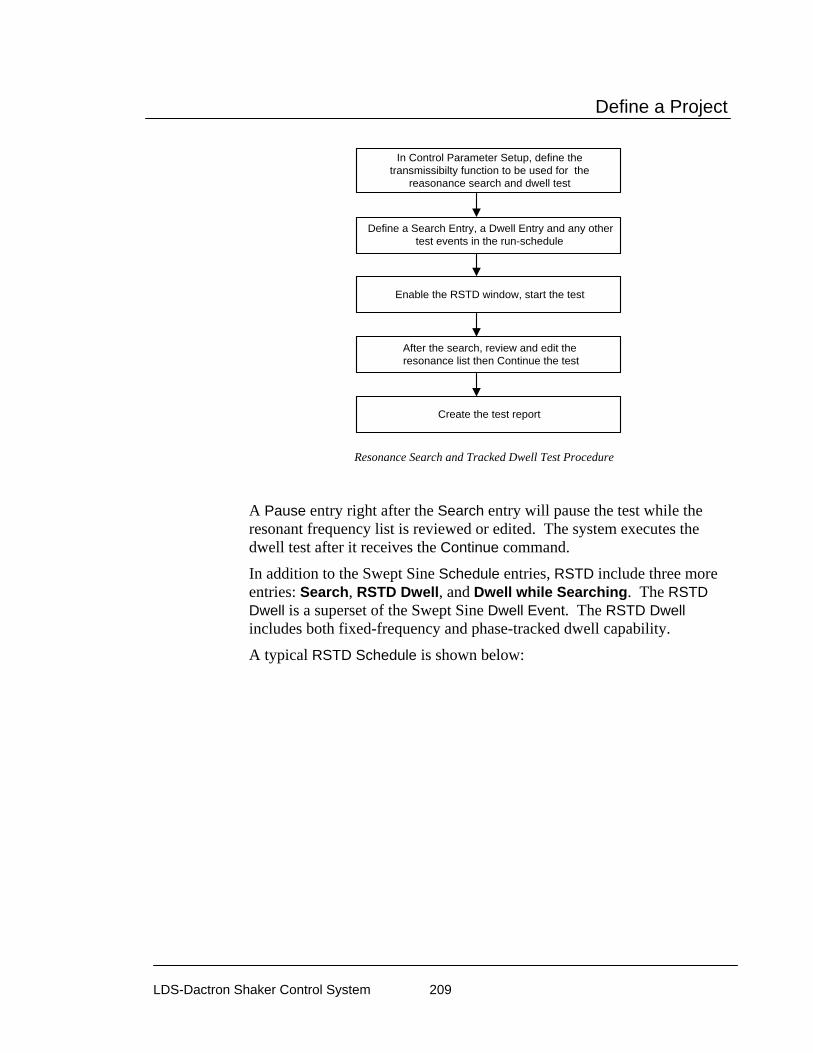
Define a Project
LDS-Dactron Shaker Control System 209
In Control Parameter Setup, define thetransmissibilty function to be used for the
reasonance search and dwell test
Enable the RSTD window, start the test
Define a Search Entry, a Dwell Entry and any othertest events in the run-schedule
After the search, review and edit the resonance list then Continue the test
Create the test report
Resonance Search and Tracked Dwell Test Procedure
A Pause entry right after the Search entry will pause the test while the resonant frequency list is reviewed or edited. The system executes the dwell test after it receives the Continue command.
In addition to the Swept Sine Schedule entries, RSTD include three more entries: Search, RSTD Dwell, and Dwell while Searching. The RSTD Dwell is a superset of the Swept Sine Dwell Event. The RSTD Dwell includes both fixed-frequency and phase-tracked dwell capability.
A typical RSTD Schedule is shown below:
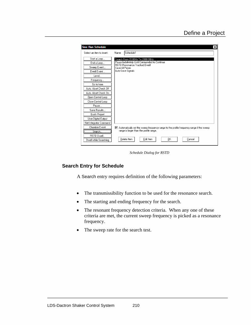
Define a Project
LDS-Dactron Shaker Control System 210
Schedule Dialog for RSTD
Search Entry for Schedule
A Search entry requires definition of the following parameters:
• The transmissibility function to be used for the resonance search.
• The starting and ending frequency for the search.
• The resonant frequency detection criteria. When any one of these criteria are met, the current sweep frequency is picked as a resonance frequency.
• The sweep rate for the search test.

Define a Project
LDS-Dactron Shaker Control System 211
Search Schedule Entry for RSTD
Search Using enables selection of the transmissibility function to use for the sweep search and the frequency range to search. The available transmissibility functions are determined by the setup in the Control Parameters menu. The Start and End frequencies have to be within the frequency range used for the profile.
Criteria allows you to set the thresholds for detection of resonances. Q (Quality Factor) detects resonances with Q values greater than the value specified in the menu. Q is a measure of the damping, or sharpness, of a resonance. The higher the Q value, the sharper the resonant peak. Amplitude ratio detects resonances for which the transmissibility amplitude value is greater that the specified threshold value. Min interval between resonances allows you to specify the minimum frequency interval between resonances found. If you are uncertain as to the values to expect for the transmissibility function set Q (Quality Factor) to 5 or less and Amplitude ratio to 2 or less. These two detection criteria can be used jointly or independently to allow you to screen the resonance detection results and identify only the most significant resonances.

Define a Project
LDS-Dactron Shaker Control System 212
Transmissibility Transmissibility
Amplitude ratio threshold
f0f1 f0 f2
half-power
Q = f0/(f2-f1) Amplituderatio
threshold
Q Quality factor threshold
Advanced Sweep Rate Setting allows you to use a rate different rate than the Default Sweep Rate defined in the Control Parameters. To specify a special sweep rate for a Schedule event, select Special Sweep Rate and enter the sweep rate in the edit box. Note that the Sweep Type (Linear or Logarithmic) setting in the Control Parameters determines the sweep rate units. If the Sweep Type is Linear, the unit is in either Hz/sec or Minute/Cycle. If the Sweep Type is Log, the sweep unit will be either Octave/Minute or Minute/Cycle.
Dwell Entry for Schedule
There are two dwell types in RSTD: Frequency-Locked Dwell and Phase-Tracked Dwell. For Frequency-Locked Dwell, the frequency stays at the initial dwell frequency. It does not change even if the resonance frequency drifts.
For Phase-Tracked Dwell, the dwell frequency changes to follow any drift of the resonance frequency.
Make your selection of a dwell technique by clicking on the appropriate checkbox.
The RSTD Dwell entry allows specification of conditions that trigger a stop of the dwell test. Criteria for completion of the dwell test include:
• Dwell time
• Dwell sine cycles
• Resonant frequency drift (in Hz or percent of resonant frequency)
• Resonant frequency drift per time period
• Amplitude drift
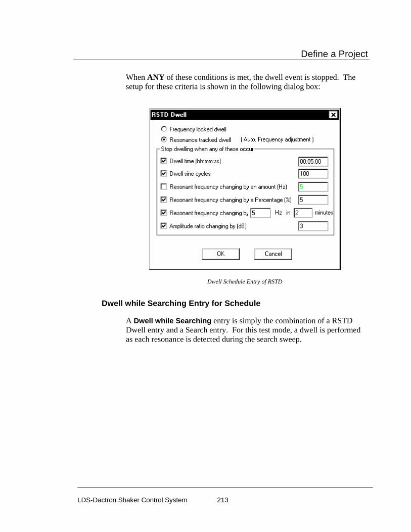
Define a Project
LDS-Dactron Shaker Control System 213
When ANY of these conditions is met, the dwell event is stopped. The setup for these criteria is shown in the following dialog box:
Dwell Schedule Entry of RSTD
Dwell while Searching Entry for Schedule
A Dwell while Searching entry is simply the combination of a RSTD Dwell entry and a Search entry. For this test mode, a dwell is performed as each resonance is detected during the search sweep.

Define a Project
LDS-Dactron Shaker Control System 214
Search and Dwell Schedule Entry for RSTD
RSTD Dwell Test Using Saved Transmissibility Functions
To save time you can make an RSTD search, save the measured transmissibility functions, and then use one of the saved transmissibilities to seed the RSDT dwell table. This capability is accessed via the Dwell Table Seeding menu found under the Test Setup menu.

Define a Project
LDS-Dactron Shaker Control System 215
In the Dwell Table Setup dialog first click on the Resonance Freq, Search Criteria button to set up the resonance detection criteria.
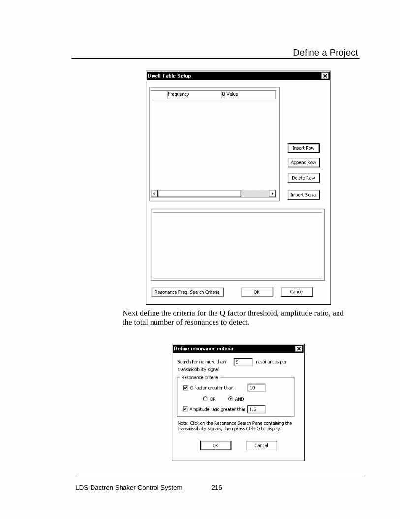
Define a Project
LDS-Dactron Shaker Control System 216
Next define the criteria for the Q factor threshold, amplitude ratio, and the total number of resonances to detect.
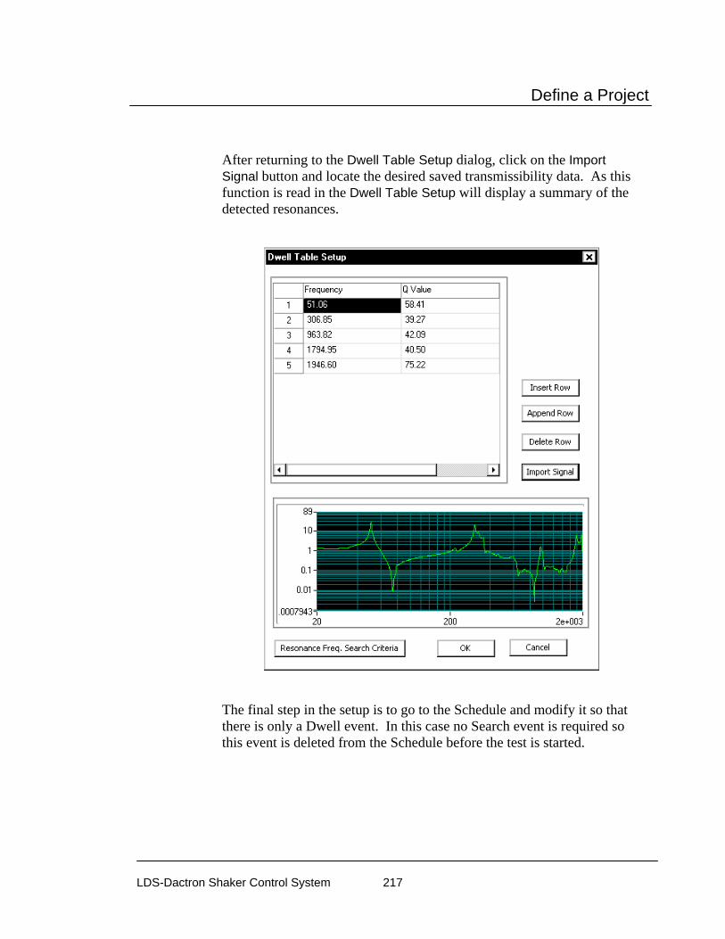
Define a Project
LDS-Dactron Shaker Control System 217
After returning to the Dwell Table Setup dialog, click on the Import Signal button and locate the desired saved transmissibility data. As this function is read in the Dwell Table Setup will display a summary of the detected resonances.
The final step in the setup is to go to the Schedule and modify it so that there is only a Dwell event. In this case no Search event is required so this event is deleted from the Schedule before the test is started.

Define a Project
LDS-Dactron Shaker Control System 218
Test & Profile Setup – Classical Shock, SRS, & TTH
This Section describes the Test Setup and Profile menus and dialog boxes for Classical Shock, Shock Response Spectrum (SRS) Transient Control, and Transient Time History Control (TTH) Projects.
Control Parameters for Classical Shock, SRS Synthesis, and TTH
For a Shock Project, the Control Parameters menu has four pages; Test, Filter, Pre-Test and SRS Analysis.
Test Page for Shock, SRS Synthesis, and TTH Control Parameters
The Test page defines the parameters for measuring and updating the system transfer function and the measurement process controls. It also includes a number of safety settings.
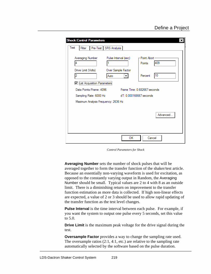
Define a Project
LDS-Dactron Shaker Control System 219
Control Parameters for Shock
Averaging Number sets the number of shock pulses that will be averaged together to form the transfer function of the shaker/test article. Because an essentially non-varying waveform is used for excitation, as opposed to the constantly varying output in Random, the Averaging Number should be small. Typical values are 2 to 4 with 8 as an outside limit. There is a diminishing return on improvement to the transfer function estimation as more data is collected. If high non-linear effects are expected, a value of 2 or 3 should be used to allow rapid updating of the transfer function as the test level changes.
Pulse Interval is the time interval between each pulse. For example, if you want the system to output one pulse every 5 seconds, set this value to 5.0.
Drive Limit is the maximum peak voltage for the drive signal during the test.
Oversample Factor provides a way to change the sampling rate used. The oversample ratios (2:1, 4:1, etc.) are relative to the sampling rate automatically selected by the software based on the pulse duration.
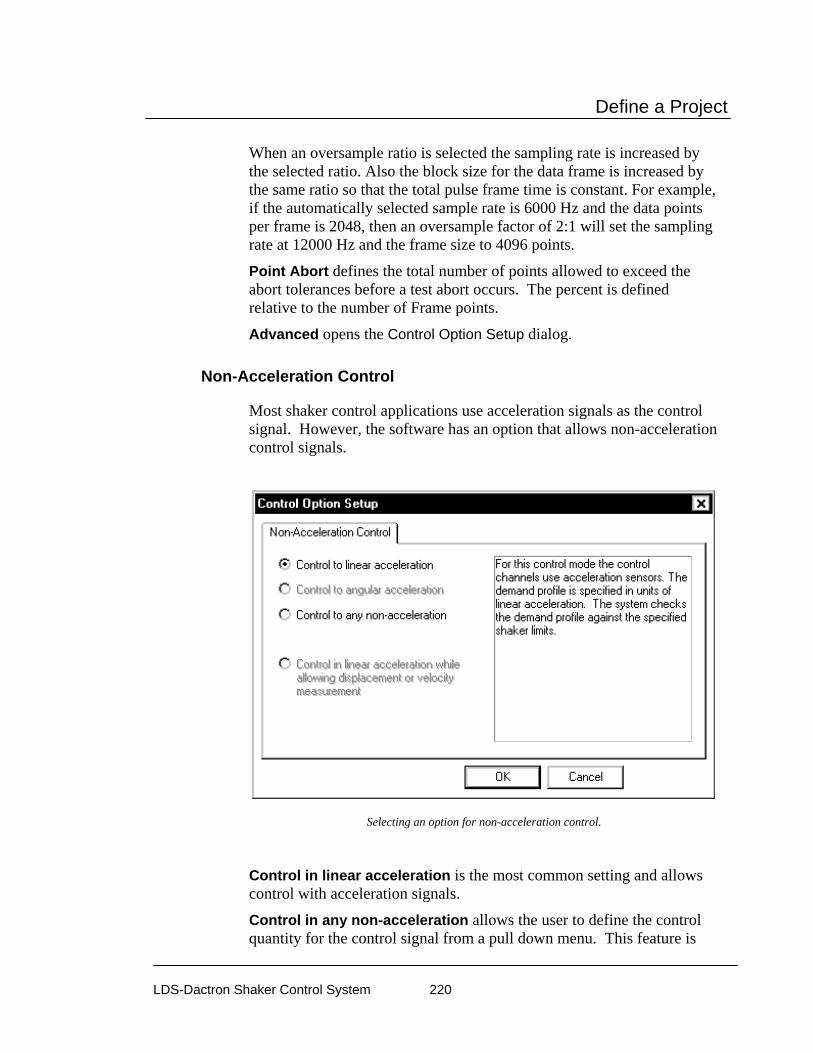
Define a Project
LDS-Dactron Shaker Control System 220
When an oversample ratio is selected the sampling rate is increased by the selected ratio. Also the block size for the data frame is increased by the same ratio so that the total pulse frame time is constant. For example, if the automatically selected sample rate is 6000 Hz and the data points per frame is 2048, then an oversample factor of 2:1 will set the sampling rate at 12000 Hz and the frame size to 4096 points.
Point Abort defines the total number of points allowed to exceed the abort tolerances before a test abort occurs. The percent is defined relative to the number of Frame points.
Advanced opens the Control Option Setup dialog.
Non-Acceleration Control
Most shaker control applications use acceleration signals as the control signal. However, the software has an option that allows non-acceleration control signals.
Selecting an option for non-acceleration control.
Control in linear acceleration is the most common setting and allows control with acceleration signals.
Control in any non-acceleration allows the user to define the control quantity for the control signal from a pull down menu. This feature is

Define a Project
LDS-Dactron Shaker Control System 221
commonly used for force, velocity, or displacement control. When this option is enabled, the shaker limits are not checked. It is critical that the user ensure that the profile will not exceed the shaker limits and cause damage to the system. When this option is enabled then the Channel Parameters and Profile are automatically changed to the specified control quantity
If non-acceleration control is selected, then you must specify the type of sensor to be used for control.
Filter Page for Shock, SRS Synthesis, and TTH Control Parameters
Shock control is a time domain process. Unlike Random and Sine, it is very sensitive to high frequency noise. A low-pass filter can be used to help suppress noise. The filter is applied to the profile first, so that the required time domain waveform will not contain unrealistic high-frequency content. The filter will distort the profile waveform to some extent. If you decide to apply the filter, make sure you go back to the profile setup and check the profile waveform.
To avoid heavy distortion of the profile, you should use an “experience formula.” The experience formula defines a low frequency cutoff. The experience formula states that you should not apply a filter with a cutoff frequency lower than:

Define a Project
LDS-Dactron Shaker Control System 222
(4.0/PulseWidth) (Hz)
For example, if the pulse width is 10ms, the cutoff frequency of the filter applied should be higher than 4/0.01sec = 400 Hz.
The same low-pass filter will be applied to the drive signal to ensure suppression of the undesired high-frequency component.
Even when the output is filtered with this low-pass filter, the shaker system will “reinstate” high frequency noise into the response signal. To overcome this effect, the same low-pass filter is applied to the response signals.
Options for Low-Pass Filtering
Do not apply filter inhibits any low-pass filtering. Apply filter using “Maximum Drive Frequency” in Shaker Parameters uses the information that you have entered for the shaker. This selection is generally a good overall choice for the filter setting.
Apply filter with user-defined cut-off frequency invokes a numerical entry box that allows you to set a filter cut-off frequency.

Define a Project
LDS-Dactron Shaker Control System 223
Pre-Test Page for Shock, SRS Synthesis, and TTH Control Parameters
Methods and goals for the initial test equalization phase are defined in the Pre-Test page.
Pre-Test Control Parameters for Shock
Method of Acquiring the Loop Frequency Response Function (FRF) offers the following equalization methods:
Measure during Pre-Test is the preferred method of achieving the FRF that will be used during the scheduled test.
Use Current Active Function and Skip Pre-Test should be used only when the test has just been run successfully and nothing else has changed. Use this function only when extreme care has been taken to ensure that the test is being repeated with no changes. A change of just a few hours of test time is sometimes enough to have a significant effect on the running of a test.
Define a Project
LDS-Dactron Shaker Control System 224
Recall Function From Disk And Skip Pre-Test is used when you are absolutely sure that the FRF stored on disk is exactly the same as the current conditions. Use this selection only with extreme care.
Initial Drive is the start voltage for the beginning of the output waveform to be generated.
Ramp-up Rate sets the speed with which the amplitude is going to increase. Take into consideration the response time of your entire shaker system for this setting. Avoid “Shocking” the system. A shock to the system would involve a ramp-up speed that exceeds the ability of the shaker system to respond to dynamic changes. Generally, Fast Ramp-up works well with linear systems such as electrodynamic shaker systems. For hydraulic shaker systems, which are very non-linear, the best choice is Slow Ramp-up.
Response Level Goal is the amplitude level control signal is expected to achieve during the pre-test. Successfully achieving this level will confirm that the system is ready to run the test.
Maximum Drive is the drive limit, in voltage, for the pre-test process.
Use inverse pulse as pre-test profile allows pre-test measurement of Hinv using a pulse with negative polarity.
Skip Pre-Test Report and Start Scheduled Test provides the option to bypass the pre-test report, displayed after completion of the pre-test, and immediately start the Run Schedule. If this option is not selected (not checked), then the pre-test report is displayed and the operator must give a Proceed command to start the Run Schedule. Note that the normal pre-test safety checks remain active regardless of the selection here. If there is an open-loop condition, if the maximum drive voltage is reached, or the desired response goal level is not achieved, then the pre-test will abort. Usually this selection is active (checked) when the Digital I/O and Project Sequence functions are used.
SRS Analysis Page of Shock, SRS Synthesis, and TTH Control Parameters
The final page defines the SRS Analysis parameters.

Define a Project
LDS-Dactron Shaker Control System 225
SRS Analysis Dialog for Shock
Enable allows you to enable or disable SRS analysis capability. Once enabled, SRS analysis will be applied to all enabled input channels (the channels with either Control or Monitor turned on). To view the SRS results, select Pane and look for signal names with “SRS” in the signal candidate category. For example, if channel 2 is enabled, you will see AbsSRS2(f), PosSRS2(f) and NegSRS2(f). Here the AbsSRS(f) means the Maxi-maximum SRS signal. The PosSRS(f) means the positive SRS signal and NegSRS(f) the negative SRS signal.
The parameters for SRS Analysis are:
Low Frequency Bound establishes the lowest frequency for the SRS.
High Frequency Bound establishes the highest frequency for the SRS.
Reference Frequency is the frequency that will be used to compute the frequency points across the frequency range specified.

Define a Project
LDS-Dactron Shaker Control System 226
Damping Ratio(%) is the damping coefficient ζ used to calculate the SRS:
ς = ckm2
Where c is the damping, k the stiffness, m the the mass of the SRS single-degree-of-freedom system. Enter a number in percentage for the damping ratio. For example, for ζ=5%, enter the number “5”.
Q (Quality Factor) is the Q value of the SDOF filter. If a value is entered for Q, the Damping Ratio value is automatically changed to a corresponding value.
Fractional Octave Number determines the spacing of frequency components for the SRS.
The frequency points, i.e., the resonant frequencies of the bank of SDOF systems for SRS analysis, are determined by:
Frequency j f j N[ ] /= 0 2
Where f0 is the reference frequency; 1/N is the fractional octave number and j is an integer going through the range so that all frequencies governed by high- and low-frequency bounds are covered ( plus one additional frequency at the left bound and another at the right bound).
For example:
Low-Frequency Bound = 100Hz
High-Frequency Bound = 10,000Hz
Reference Frequency = 1,000Hz
Fractional Octave Number is 1/1
In this case, the SRS will have following frequency points: 62.5, 125, 250, 500,1000, 2000, 4000, 8000, 16000Hz

Define a Project
LDS-Dactron Shaker Control System 227
Control Parameters for TTH TTH allows additional choices for the pre-test transfer function measurement (Hsys). These choices provide greater flexibility in compensating for the dynamics of the shaker system and test article.
Pre-Test Parameters for TTH
The initial equalization methods available in TTH include:
Measure during close-loop pre-test: The Hsys is estimated using the profile waveform as the initial excitation signal. After the initial estimate of the Hsys is made, the drive signal is modified so that the control signal matches the profile. This is the same method used in Classical Shock.
Use current active function and skip pre-test: The Hsys for the previous test will be used if that test was saved to the disk with the Save

Define a Project
LDS-Dactron Shaker Control System 228
Frequency Response Signal command. This method is also offered in Shock.
Recall function from disk and skip pre-test: If the Hsys for any previous test has been saved to disk with any of the methods of saving signals, the system will recall and use that Hsys. This method is also offered in Shock.
Open-loop output random noise: In this method, a white-noise signal is output to drive the shaker and the Hsys is estimated. This Hsys estimation technique can be tailored by specifying the peak voltage for the random excitation signal and the number of the frames to be output in the pre-test. With random excitation, a larger number of frames are needed to get a good estimation of the Hsys. Typically, between 8 and 16 frames are required.
Open-loop output shaped random noise: This method is the same as the previous method with one added feature. The random signal is shaped in the frequency domain so that it has a spectral shape similar to that of the profile waveform. This method provides better Hsys estimation accuracy in the frequency range corresponding to the profile waveform’s frequency components.
Open-loop output of profile(t): The drive uses the profile waveform itself. This technique works well for systems with linear dynamic response characteristics. This Hsys estimation technique can be tailored by specifying the peak voltage for the excitation signal and the number of the frames to be output in the pre-test. With this method a smaller number of frames is needed to get a good estimation of the Hsys. Typically, only 4 to 8 frames are required.
Warning: The last three methods all use open loop drive output. These methods do not gradually increase the output level as the system transfer function is measured during pre-test. The drive output is at a constant level set by the Peak Output (volts) entry in the Pre-Test menu. If you set this entry to be 2 volts then the system will output a waveform with a peaks up to + 2 volts for every output during the pre-test. The user should be extremely cautious about choosing a safe peak voltage for the drive output. A low Peak Output voltage value should be used – typically 0.1 Volts or less
Preferences for Shock, SRS Synthesis, and TTH

Define a Project
LDS-Dactron Shaker Control System 229
The Controls page of the Preferences dialog box provides for programming the rate of change of the drive signal during a test shutdown or during a level change in the course of a pre-test or test. It also allows you to pre-program the incremental change to a drive signal under manual level control.
Control Preferences for Shock
Enable resume from abort allows, if the box is checked, resuming a test after an abort. The full level pulses elapsed count resumes at the number it was at when the test aborted and the test runs until the remaining full level pulse count is reached.
Enable resume from abort allows, if the box is checked, resuming a test after an abort. The full level elapsed time resumes at the time that the test aborted and the test runs until the remaining full level time

Define a Project
LDS-Dactron Shaker Control System 230
expires. When this option is enabled an Options button is shown that allows customizatiojn of the resume feature as show below.
Saving a project at the time a test is halted makes it possible to resume this test as part of resumed Project Sequence. Level Change Rate
Increment for Changing Level is used during testing by manual commands for Increase Level and Decrease Level. These menu commands change the Demand Peak level.
Profile for Classical Shock A compensated waveform profile consists of five parts: pre-pulse, pre-pulse tail, main pulse, post-pulse tail and post pulse, as shown below:
pre-pulse
pre-pulse tail post-pulse tail
post pulsemain pulse
Pulse and Compensation Definitions for Classical Pulses

Define a Project
LDS-Dactron Shaker Control System 231
See Section 9, “Shaker Vibration Control Theory”, for background information on testing and control with classical shock waveforms.
The Shock Profile dialog consists of three pages: Waveform, Compensate and Abort Settings.
Waveform Page for Classical Shock Profile
The type of classical pulse and main pulse definition parameters are selected in the Waveform page.
Profile Dialog for Classical Shock
Name provides a user-entered label for the waveform.
Pulse Type is the type of classical waveform that will be used. You can choose a Half Sine, Terminal Peak Sawtooth, Initial Peak Sawtooth, Triangle, Rectangular, Trapezoid, or Haversine pulse as the test reference profile.
Amplitude specifies the peak of the waveform in the unit of acceleration.
Pulse Width specifies the duration of the classical pulse.

Define a Project
LDS-Dactron Shaker Control System 232
Main Pulse Tails lets you select the default MIL-STD810 specification for the waveform or invoke a customized waveform. Customized allows you to specify the pre- and post-pulse tails as a percentage of the pulse width.
Compensate Page for Classical Shock Profile
The Compensate page compensates the waveform for safe use with the shaker. Compensation is necessary to ensure that the ending acceleration, velocity, and displacements are all zero. This means that the shaker table begins at and returns to its normal static (rest) position.
Profile Compensation Dialog for Classical Shock Profile.
Define a Project
LDS-Dactron Shaker Control System 233
Compensate Template defines the compensation technique. The choices are as follows:
• Pre-Half Sine
• Post-Half Sine
• Pre-and Post Half Sine (default)
• Pre-Rectangular
• Post-Rectangular
• Pre-and Post Rectangular
• Pre- and Post-Double Rectangular
• Pre- and Post-Triangular
• Pre- and Post-Rounded-Double Rectangular
• Displacement Optimum
Pre-pulse height is the peak acceleration amplitude of the pre-pulse as a percent of the main pulse peak acceleration.
Post-pulse height is the peak acceleration amplitude of the post-pulse as a percent of the peak main peak acceleration.
Draw Shaker Limits overlays the shaker acceleration, velocity, and displacement limits on the corresponding pulse waveform display.
Shaker Limits lists the critical shaker performance limits for comparison to the dynamic limits for the profile.
In the Load section you can specify the masses for the DUT and Jig. These masses are used together with the shaker armature mass and the acceleration demand of the profile to estimate the peak force required for the test. Click on Load Library to define a set of DUT and Jig masses as show in the figure below.

Define a Project
LDS-Dactron Shaker Control System 234
Once the Load library has been set up then any combination of DUT and Jig masses may be selected in the Vibration Limits page.
Abort Settings Page for Classical Shock Profile
The Aborts Settings allows you to select either the MIL-STD810 abort settings or Customized Abort Limits. Selecting Customized will invoke additional numerical dialogs so that you may describe your customized abort limits.
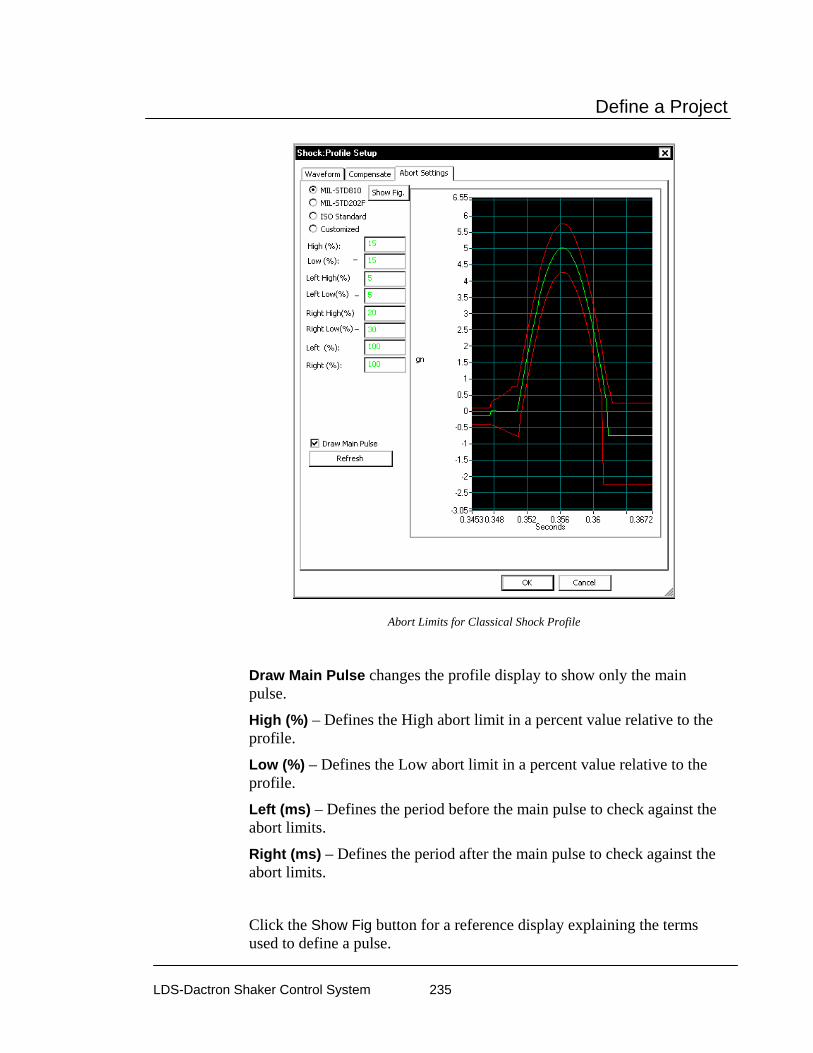
Define a Project
LDS-Dactron Shaker Control System 235
Abort Limits for Classical Shock Profile
Draw Main Pulse changes the profile display to show only the main pulse.
High (%) – Defines the High abort limit in a percent value relative to the profile.
Low (%) – Defines the Low abort limit in a percent value relative to the profile.
Left (ms) – Defines the period before the main pulse to check against the abort limits.
Right (ms) – Defines the period after the main pulse to check against the abort limits.
Click the Show Fig button for a reference display explaining the terms used to define a pulse.
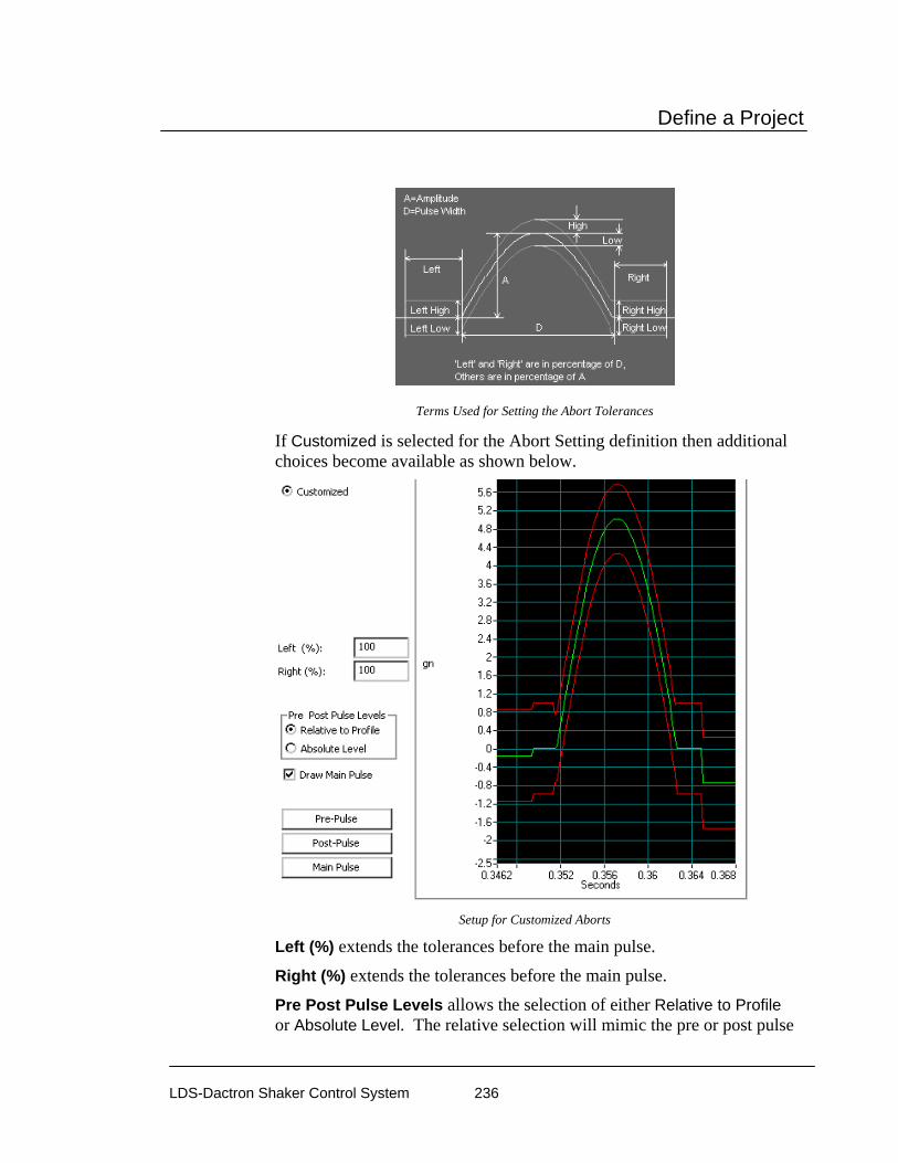
Define a Project
LDS-Dactron Shaker Control System 236
Terms Used for Setting the Abort Tolerances
If Customized is selected for the Abort Setting definition then additional choices become available as shown below.
Setup for Customized Aborts
Left (%) extends the tolerances before the main pulse.
Right (%) extends the tolerances before the main pulse.
Pre Post Pulse Levels allows the selection of either Relative to Profile or Absolute Level. The relative selection will mimic the pre or post pulse
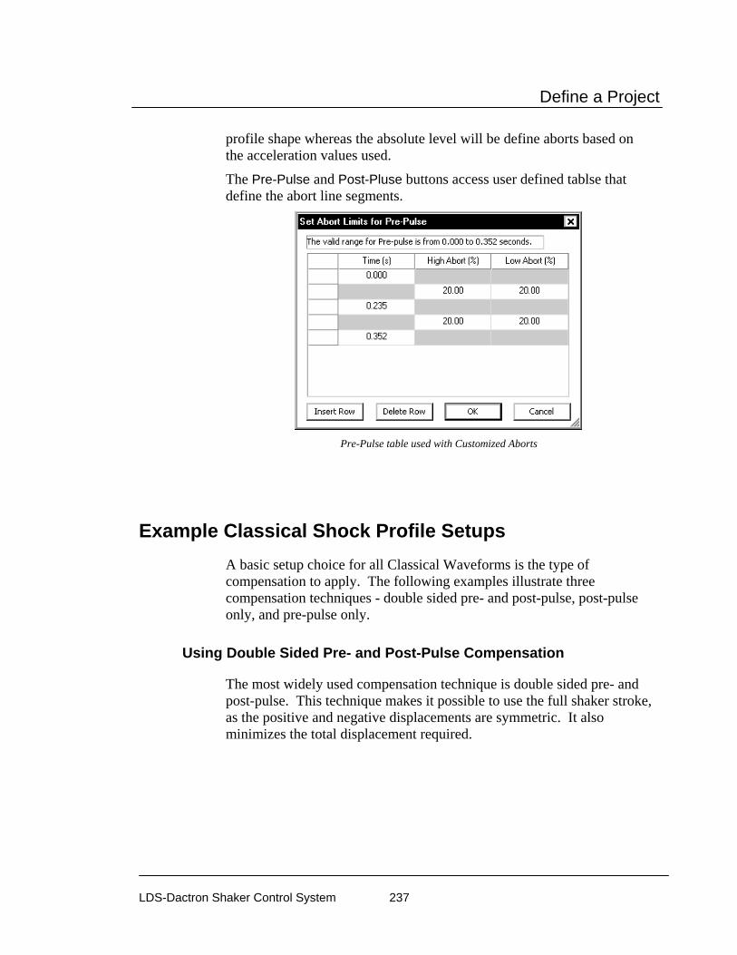
Define a Project
LDS-Dactron Shaker Control System 237
profile shape whereas the absolute level will be define aborts based on the acceleration values used.
The Pre-Pulse and Post-Pluse buttons access user defined tablse that define the abort line segments.
Pre-Pulse table used with Customized Aborts
Example Classical Shock Profile Setups A basic setup choice for all Classical Waveforms is the type of compensation to apply. The following examples illustrate three compensation techniques - double sided pre- and post-pulse, post-pulse only, and pre-pulse only.
Using Double Sided Pre- and Post-Pulse Compensation
The most widely used compensation technique is double sided pre- and post-pulse. This technique makes it possible to use the full shaker stroke, as the positive and negative displacements are symmetric. It also minimizes the total displacement required.

Define a Project
LDS-Dactron Shaker Control System 238
Double Sided Pre- and Post-Pulse Compensation Minimizes Displacement
Using Post-Pulse Only Compensation
Post-pulse only compensation is generally used when the test requires that there be no excitation of the test article prior to the main pulse itself. With this technique the displacement is single sided, either entirely in the negative or positive direction, and the total displacement is higher.

Define a Project
LDS-Dactron Shaker Control System 239
Post-Pulse Only Compensation
Using Pre-Pulse Only Compensation
The pre-pulse only compensation technique makes it possible to observe the “free” ringing of the test article after the pulse excitation. However, this technique has the drawbacks that the displacement is single sided, either entirely in the negative or positive direction, and the total displacement is higher.

Define a Project
LDS-Dactron Shaker Control System 240
Pre-Pulse Only Compensation
Profile for SRS Synthesis Preparing the reference waveform is a three-step process.
1) Specify a Required Response Spectrum (RRS).
2) Synthesize a waveform matching the energy content of the RRS.
3) Compensate the waveform to ensure zero final acceleration, velocity, and displacement on the shaker.
Required Response Spectrum (RRS) for SRS Profile
The Required Response Spectrum page permits entry of acceleration versus frequency profile. Breakpoints are entered into a spreadsheet style table to generate the RRS.

Define a Project
LDS-Dactron Shaker Control System 241
Required Spectrum Profile for Shock Synthesis
Each breakpoint is created by entering a Frequency value and an Acceleration PSD Level in each numbered row. Every numbered row is followed by an additional row that indicates the slope between each PSD Level. When a table is defined only by PSD Levels then the slopes are automatically calculated.
The slope between breakpoints can be defined by entering a value in the Slope column below each numbered row.
The last two columns define the high-abort and low-abort limits. These limits define abort conditions on a frequency-point-by-point basis for the RRS. You can enter the low-alarm and low-abort values without a negative sign.
If there is an inconsistency between breakpoint segments, the system will display a crossover frequency error message and abort the profile generation process. If there are no breakpoint inconsistencies, the Profile is generated. Also, at this time the low-abort values will automatically be converted to negative values.
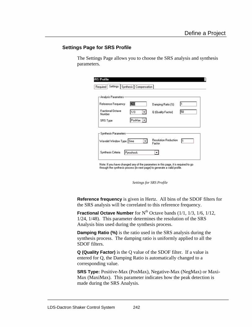
Define a Project
LDS-Dactron Shaker Control System 242
Settings Page for SRS Profile
The Settings Page allows you to choose the SRS analysis and synthesis parameters.
Settings for SRS Profile
Reference frequency is given in Hertz. All bins of the SDOF filters for the SRS analysis will be correlated to this reference frequency.
Fractional Octave Number for Nth Octave bands (1/1, 1/3, 1/6, 1/12, 1/24, 1/48). This parameter determines the resolution of the SRS Analysis bins used during the synthesis process.
Damping Ratio (%) is the ratio used in the SRS analysis during the synthesis process. The damping ratio is uniformly applied to all the SDOF filters.
Q (Quality Factor) is the Q value of the SDOF filter. If a value is entered for Q, the Damping Ratio is automatically changed to a corresponding value.
SRS Type: Positive-Max (PosMax), Negative-Max (NegMax) or Maxi-Max (MaxiMax). This parameter indicates how the peak detection is made during the SRS Analysis.

Define a Project
LDS-Dactron Shaker Control System 243
Note: It is possible to use a different set of SRS parameters during the test. For example, you can synthesize the waveform with a Frequency Resolution of 1/3, but analyze it with a higher resolution such as 1/24. The system default is to make the analysis parameters identical to the synthesis parameters.
Wavelet window types are Sine, Hann , Exponential, or Rectangular window. The data window selected will be applied to each individual wavelet. A good feature of the Sine window is that it generates a time waveform with zero ending velocity and zero ending displacement. Use Exponential if you want to synthesize a waveform with damped sins. However, note that the final displacement values will not be zero and you need to add compensation to the pulse.
Sine Wavelet
Hann Wavelet

Define a Project
LDS-Dactron Shaker Control System 244
Exponential Wavelet
Rectangular Wavelet
Resolution reduction factor automatically deactivates every Nth wavelet, N=2 to 48. The default value is 1 (no reduction). In some cases with an octave resolution of 1/6 or finer a value of less than 1 is required because the interaction of the closely spaced wavelets makes it difficult to match the required SRS profile.
Synthesis Criteria lets you select Pyroshock, Minimum Acceleration, or User Defined Duration synthesis techniques. Pyroshock acts to minimize the pulse duration and provides a more realistic simulation of pyroshock events. Minimum Acceleration spreads the time delays of wavelets across the entire output frame so that the peak acceleration level is minimized. User Defined Duration allows you specify the pulse duration in milliseconds.
SRS Synthesis Page for SRS Profile
The software uses the wavelet parameters and synthesis parameters to automatically generate wavelets for each of the Nth octave bands. The wavelets are combined (synthesized) to produce an initial estimate of the

Define a Project
LDS-Dactron Shaker Control System 245
composite transient waveform. The SRS of that waveform is calculated and overlaid in a graphic display with the RRS. If the initial estimate has converged to the RRS, you then have two choices: accept it and move on to Compensation; or modify synthesis parameters and/or individual wavelet parameters and then manually initiate any number of iterations to influence the convergence.
In general, these are the steps to define an SRS Synthesis profile:
1) Define Required SRS (Required page), SRS Analysis and Synthesis Parameters (Settings page).
2) Click on the Re-Initialize button to enter the value into the table.
3) Click on the One Step button a few times so that the synthesized SRS is close to RRS.
4) Click on the Waveform Compensation tab to perform waveform compensation.
Waveform Synthesis Table for SRS Synthesis
Re-Initialize regenerates the entire synthesis table. The system will make a first-time guess on the Half Cycles, Delays and Wavelet Amplitudes. The user should use this button after each change to the RRS, the SRS Analysis Parameters, or the SRS Synthesis Parameters.
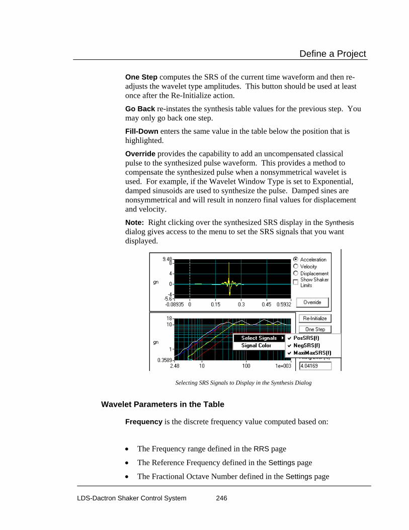
Define a Project
LDS-Dactron Shaker Control System 246
One Step computes the SRS of the current time waveform and then re-adjusts the wavelet type amplitudes. This button should be used at least once after the Re-Initialize action.
Go Back re-instates the synthesis table values for the previous step. You may only go back one step.
Fill-Down enters the same value in the table below the position that is highlighted.
Override provides the capability to add an uncompensated classical pulse to the synthesized pulse waveform. This provides a method to compensate the synthesized pulse when a nonsymmetrical wavelet is used. For example, if the Wavelet Window Type is set to Exponential, damped sinusoids are used to synthesize the pulse. Damped sines are nonsymmetrical and will result in nonzero final values for displacement and velocity.
Note: Right clicking over the synthesized SRS display in the Synthesis dialog gives access to the menu to set the SRS signals that you want displayed.
Selecting SRS Signals to Display in the Synthesis Dialog
Wavelet Parameters in the Table
Frequency is the discrete frequency value computed based on:
• The Frequency range defined in the RRS page
• The Reference Frequency defined in the Settings page
• The Fractional Octave Number defined in the Settings page

Define a Project
LDS-Dactron Shaker Control System 247
RRS Value is the discrete value of the RRS translated from the breakpoint table.
Half Cycles define the duration of this wavelet. The user should assign an odd number to this field in order to make the ending velocity or displacement less. However, if the High-Pass filter in the waveform compensation is applied, any value can be used. The system initializes this column during the initial stage. If the number set is less than 5, the wavelet will make a very insignificant contribution to the frequency. This parameter can be manually changed.
Delay defines the time delay relative to the beginning of the waveform. The system initializes this column during the initial stage. This parameter heavily influences the peak acceleration, velocity, and displacement. This parameter can be manually changed.
Wavelet Amplitude sets the amplitude of each wavelet. This parameter can be manually changed if the SRS deviates from the RRS at a particular frequency.
Synthesized Amplitude is the amplitude of the SRS of the synthesized waveform. It is displayed here to enable comparison with the RRS value.
To see the contribution of any individual wavelet, in both the pulse waveform and the SRS, double-click on a wavelet number (under the Wavelet column).
Compensation Page for SRS Profile
Compensation Techniques: There are two techniques for compensating the pulse waveform to bring the final acceleration, velocity, and displacement values to zero. DC Remove eliminates any DC offset in the pulse waveform. The High-Pass Filter eliminates any frequency content below the specified cutoff frequency. This technique will also eliminate any DC offset.

Define a Project
LDS-Dactron Shaker Control System 248
Waveform Compensation Techniques for SRS Synthesis
Example SRS Synthesis Profile Setup The following figures illustrate a typical SRS with the profile waveform synthesize using the three Synthesis Criteria. The first waveform uses the pyroshock technique. The second waveform sets the waveform duration to 400 ms (by using the User Defined Duration option). In the third waveform a Minimum Acceleration technique is used.
The pyroshock technique gives the highest g levels and it has the shortest duration. Specifying the duration to be 400 ms produces a waveform similar to the pyroshock case but with lower g levels. The minimum acceleration waveform has significantly reduced g levels. This waveform has the longest duration as the wavelets are spread out to reduce peak acceleration levels. Despite these differences, all three waveforms will produce the same SRS result.

Define a Project
LDS-Dactron Shaker Control System 249
Typical SRS Synthesis Profile

Define a Project
LDS-Dactron Shaker Control System 250
Waveform Generated using Pyroshock Synthesis Criterion
Waveform Generated using Specified Duration of 400 ms Synthesis Criterion
Waveform Generated using Minimum Acceleration Synthesis Criterion

Define a Project
LDS-Dactron Shaker Control System 251
Profile for Transient Time History (TTH) TTH allows you to import a waveform recorded in the field, make necessary changes such as displacement compensation or scaling, and then replicate the waveform on the shaker.
The control algorithm used in TTH is identical to that of Classical Shock. The unique part of TTH is importing and editing the time waveform profile.
Profile Page for TTH Profile
The Profile page allows you to import a waveform or create a waveform from an available model option.
Importing a Profile Waveform into TTH

Define a Project
LDS-Dactron Shaker Control System 252
To import a time domain waveform as the profile, click the Import from File button. This action will invoke the following dialog box:
Import from File Dialog Box
The data format must be identified in order to import data from a disk file. The Data Format field shown below allows selection of the data type.
Data Format Selection for File to Import

Define a Project
LDS-Dactron Shaker Control System 253
TTH imports the following types of the data:
LDS-Dactron Binary is the system’s default data import and export format. This format preserves all the information about the data including measurement parameters. This compact file format also minimizes the disk space required to save signal data.
LDS-Dactron ASCII Delimited files include minimal header information such as the frame size, the sampling rate, etc., written in ASCII Format. Note that there are two types of LDS-Dactron ASCII Delimited data formats: (1) Y-data only or (2) X-Y pair.
ASCII Delimited Format includes other types of ASCII delimited formats. In this case, you have to input some of the necessary information. User-supplied information includes whether the data is Y-value only or in X-Y pair, the sampling rate, and the size of the data frame to be imported.
San-Esu is a special ASCII data format defined by the San-Esu Company.
UFF Text and UFF Binary are popular industry formats. In TTH, only time domain UFF signals can be recognized and imported.
Note: MTS ATI/AFU and RPCIII formats are only available on Windows 2000 operating system and are not available in others. Shaker Control is not able to recognize MTS ATI/AFU files set with a “Read-only” attribute as defined in the MTS library. Please ensure prior to attempting to recall MTS ATI/AFU files in Shaker Control that the "Read-only" attribute has been disabled for these files.
MTS ATI Format is a binary file used with IDEAS software.
MTS AFU Format is a binary file used with MTS Noise Path Analysis software.
Agilent SDF Format is a binary data file that is an open format used with many Agilent and HP devices. The structure is published and maintained by Agilent. LDS-Dactron Wave Audio Normal Wave Audio LTH Profile
Note: When importing ASCII data it is assumed that commas are used to designate thousands and other large denominations. If periods are used, the data must be reformatted with commas used instead

Define a Project
LDS-Dactron Shaker Control System 254
of periods. For example, the number four thousand, seven hundred twenty eight, and 98/100, if represented using a period format would be 4.728.98. For the application program to correctly read this value it must be formatted as 4,728.98.
Digital Re-sampling
If the waveform sampling rate exactly matches an available sampling rate of the LDS-Dactron system, digital re-sampling is not required. This is always the case if the data was recorded with the LDS-Dactron system. However, if the imported data has a different sampling rate, digital re-sampling is required to prevent distortion of the waveform shape during output. Generally you should select Auto for the sampling Delta T field. The system also allows selection of a specific output sampling interval.
Digital re-sampling is done internally by a 5th order filter. This high-order filter ensures against the loss of signal information in the sampling bandwidth during re-sampling.
Selection List for Sampling Delta T
Creating the Profile from a Mathematical Model
TTH offers classical waveforms such as sine, chirp (a fast swept sine) or random as templates for the profile waveform. Click the Create from Model button to invoke the following dialog box:

Define a Project
LDS-Dactron Shaker Control System 255
TTH Dialog Box to Create a Profile from a Model Library
Note that the choices available in this dialog box will depend on the selection made in the Waveform Type menu.
A number of choices are available for the model waveform as shown below.
Sine allows generation of constant frequency sine wave.
Chirp provides a fast sine sweep with the initial and final frequency user specified.
White Noise is a broadband random signal with uniform energy across the frequency range of the output.
Bellcore Zone 1&2, Zone 3, and Zone 4 automatically load the seismic time histories required by the Bellcore test specification. In addition, the RRS (Required Response Spectrum) is available as a display, via the pane Contents menu, to allow direct comparison of the control SRS and the Bellcore’s RRS.

Define a Project
LDS-Dactron Shaker Control System 256
Data Editing
After the profile is imported or created, you can edit the waveform with the tools provided by the TTH.
Re-Scale applies a multiplier to the profile data array.
Scaling the Profile Waveform Amplitude
Fill In allows a range of data values to be replaced by a specified value.
TTH Dialog Box to Fill a Range of Data Points with a New Value
Go To scrolls the signal list to make the desired point the first displayed data value.

Define a Project
LDS-Dactron Shaker Control System 257
Specifying a Data Point to Go To in the Waveform Record
Also any individual data point can be changed by simply typing over the value in the signal value list.
Changing a Single Data Point Value in the Waveform Record
Reduce to Half invokes a dialog box that allows you to reduce the number of data points by discarding the first half of the frame, the last half of the frame, or the first and last quarter portions of the frame (retaining only the middle portion of the frame).

Define a Project
LDS-Dactron Shaker Control System 258
Method for reducing the data points
Compensation Page for TTH Profile
The second page of the Profile dialog box provides three waveform compensation techniques: DC Removal, High-pass Filter, Brick Wall Filter, and Pre and Post Pulses.
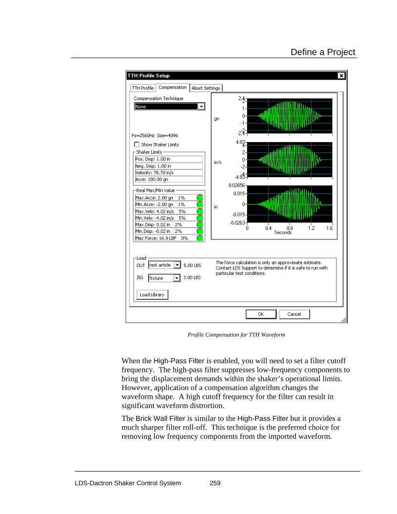
Define a Project
LDS-Dactron Shaker Control System 259
Profile Compensation for TTH Waveform
When the High-Pass Filter is enabled, you will need to set a filter cutoff frequency. The high-pass filter suppresses low-frequency components to bring the displacement demands within the shaker’s operational limits. However, application of a compensation algorithm changes the waveform shape. A high cutoff frequency for the filter can result in significant waveform distrortion.
The Brick Wall Filter is similar to the High-Pass Filter but it provides a much sharper filter roll-off. This technique is the preferred choice for removing low frequency components from the imported waveform.

Define a Project
LDS-Dactron Shaker Control System 260
Pre and Pulse Pulses adds half-sine compensation pulses before and after the pulse. These pulses ensure that the final ending values of acceleration, velocity and displacement are zero.
Abort Settings Page for TTH Profile
Positive and negative acceleration aborts limits are set as shown in the figure below. In the waveform display, the abort limits appear as upper and lower red lines.
Abort Settings Page for TTH

Define a Project
LDS-Dactron Shaker Control System 261
Example TTH Profile Setups
Generating a Burst Sine Time History
There are three simple steps involved in generating a Burst Sine time history:
1) Click the Create From Model button and set the signal type parameters. Select the Sine waveform and specify the sine frequency and amplitude values and then set the sampling frequency and the number of points.
2) Click the Data Window button and set the starting and ending taper and then Apply.
3) Apply a compensation technique to ensure zero ending velocity and displacement.
TTH Profile Setup to Generate Burst Sine Time History
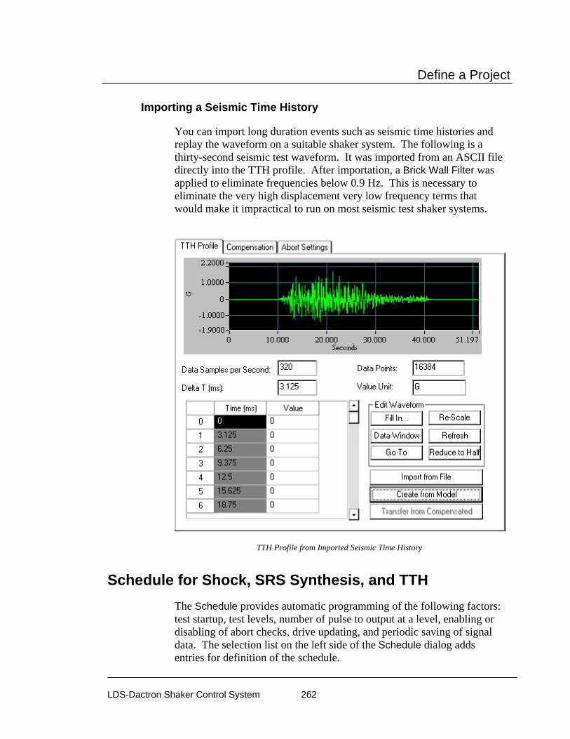
Define a Project
LDS-Dactron Shaker Control System 262
Importing a Seismic Time History
You can import long duration events such as seismic time histories and replay the waveform on a suitable shaker system. The following is a thirty-second seismic test waveform. It was imported from an ASCII file directly into the TTH profile. After importation, a Brick Wall Filter was applied to eliminate frequencies below 0.9 Hz. This is necessary to eliminate the very high displacement very low frequency terms that would make it impractical to run on most seismic test shaker systems.
TTH Profile from Imported Seismic Time History
Schedule for Shock, SRS Synthesis, and TTH The Schedule provides automatic programming of the following factors: test startup, test levels, number of pulse to output at a level, enabling or disabling of abort checks, drive updating, and periodic saving of signal data. The selection list on the left side of the Schedule dialog adds entries for definition of the schedule.

Define a Project
LDS-Dactron Shaker Control System 263
To edit an entry, either double-click it, or highlight it and click the Edit Item button. You may also Delete an item in the list or Edit one that has already been entered.
Shock Schedule Setup Dialog
Pulses at Level Event invokes a dialog box for entry of test level (relative to full test level) and the number of pulses to output at this level.
The Schedule Mode Off command pauses the test until the Continue Schedule command is given. This schedule command allows manual pulse output control. It also is used for remote test start via the Digital Input/Output function. In this case, the software waits for a Continue command from a specified Digital Input line and then executes the next item in the schedule.
Inverse Pulse reverses the polarity of the output. That is, a positive acceleration pulse becomes a negative acceleration pulse, or the other way around.

Define a Project
LDS-Dactron Shaker Control System 264
Other Shock Schedule setup options include:
Start a Loop invokes a dialog to specify the number of times that a loop will be repeated.
End a Loop closes a Loop sequence. Loops can be nested but End a Loop and Start a Loop entries must be defined as a pair.
Auto Abort Check On enables automatic Abort during the test.
Auto Abort Check Off disables automatic Abort checks. You should only disable the automatic Aborts checks if an operator monitors the test continuously. Once automatic abort checking is turned off, manual aborts are the only protection.
Open Control Loop stops updating of the measured system transfer function and other control loop update parameters. The system will continue to output the drive signal but no further change is made to the drive signal shape.
Close Control Loop enables continuous updating of the measured system transfer function and the drive signal. Normally, this mode is used for most tests.
Save Results invokes the following dialog box and lets you specify the signals to save automatically:
Dialog Box for Selecting Results to Save

Define a Project
LDS-Dactron Shaker Control System 265
Quick Report generates a test report within MS Word. This command can be used to automatically generate data plots or test reports at pre-set times or test events.
Net Integrator Command sends either a Start or Stop command to another application, such as RT-Pro, that is concurrently running.
Use Digital Output invokes the following dialog box and lets you specify which of pins 2 – 9 on digital output port two to output a TTL signal.
Programming a TTL output signal via Digital I/O Port 2.
Chamber Event invokes the following dialog box and lets you create a new or view/edit a Chamber Interface Event. See Section 4 “Schedule for Random” for more details on this dialog box.
Set a Chamber Event Dialog Box
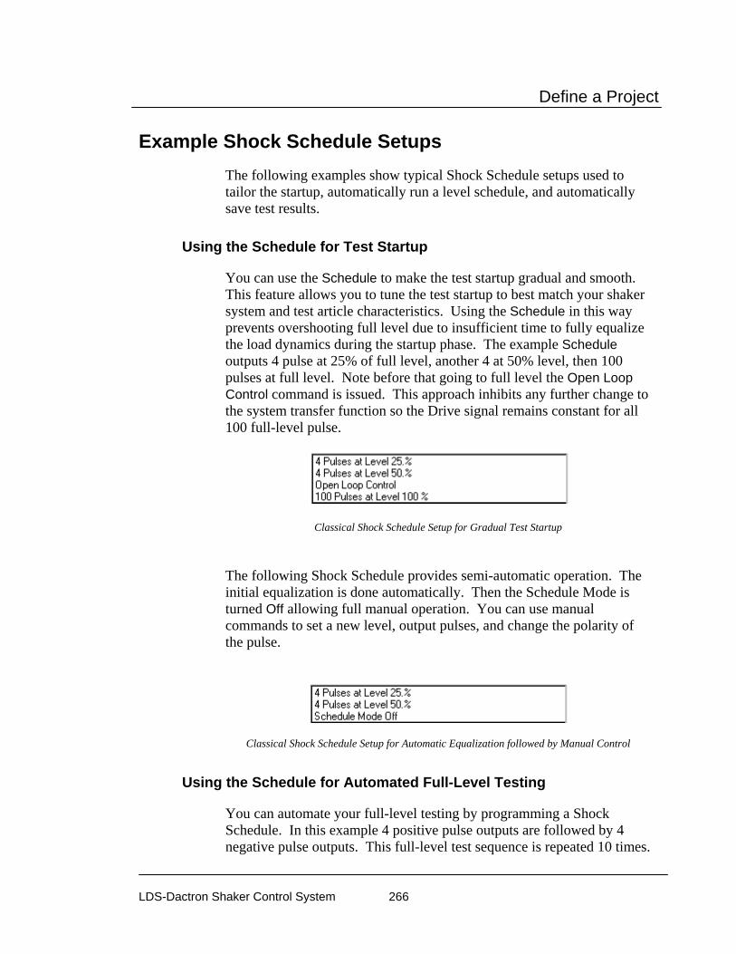
Define a Project
LDS-Dactron Shaker Control System 266
Example Shock Schedule Setups The following examples show typical Shock Schedule setups used to tailor the startup, automatically run a level schedule, and automatically save test results.
Using the Schedule for Test Startup
You can use the Schedule to make the test startup gradual and smooth. This feature allows you to tune the test startup to best match your shaker system and test article characteristics. Using the Schedule in this way prevents overshooting full level due to insufficient time to fully equalize the load dynamics during the startup phase. The example Schedule outputs 4 pulse at 25% of full level, another 4 at 50% level, then 100 pulses at full level. Note before that going to full level the Open Loop Control command is issued. This approach inhibits any further change to the system transfer function so the Drive signal remains constant for all 100 full-level pulse.
Classical Shock Schedule Setup for Gradual Test Startup
The following Shock Schedule provides semi-automatic operation. The initial equalization is done automatically. Then the Schedule Mode is turned Off allowing full manual operation. You can use manual commands to set a new level, output pulses, and change the polarity of the pulse.
Classical Shock Schedule Setup for Automatic Equalization followed by Manual Control
Using the Schedule for Automated Full-Level Testing
You can automate your full-level testing by programming a Shock Schedule. In this example 4 positive pulse outputs are followed by 4 negative pulse outputs. This full-level test sequence is repeated 10 times.

Define a Project
LDS-Dactron Shaker Control System 267
Note that level, number of pulses to output, and pulse polarity can all be specified in the Schedule.
Shock Schedule Setup for Automatic Full-Level Testing
Using the Schedule to Automatically Save Results
You can program a Schedule to automatically save results. This includes saving Signals, Panes and test screen bitmaps. This example illustrates a Schedule setup for a test that outputs a total of 100 full-level pulses. Every 10th pulse, the test results are saved. This Schedule uses a loop repeated ten times to accomplish the automatic saves. Every loop includes a command to output 10 pulses and then save all Panes and Signals.
Shock Schedule Setup to Automatically Save Results
Test & Profile Setup – Long Time History (LTH)
This section describes the Test Setup and Profile menus and dialog boxes for Long Time History (LTH) Projects.

Define a Project
LDS-Dactron Shaker Control System 268
Control Parameters for LTH For LTH projects, there are two pages in the Control Parameters dialog box: Pre-Test and Test. This menu is used to set test control methods and the pre-test process.
Test Page for LTH Control Parameters
The processing technique for closed-loop control is defined in the Test page. The procedure used to start the test (i.e., begin drive signal output) is defined in the Pre-Test page.
Control Parameters for LTH
Block Size (Points) sets the number of time domain points to use in the control loop. Selections for 1024, 2048 and 4096 are available. It is usually best to use 1024 points unless there are very sharp resonances or the test article is lightly damped then a larger block size is preferable.
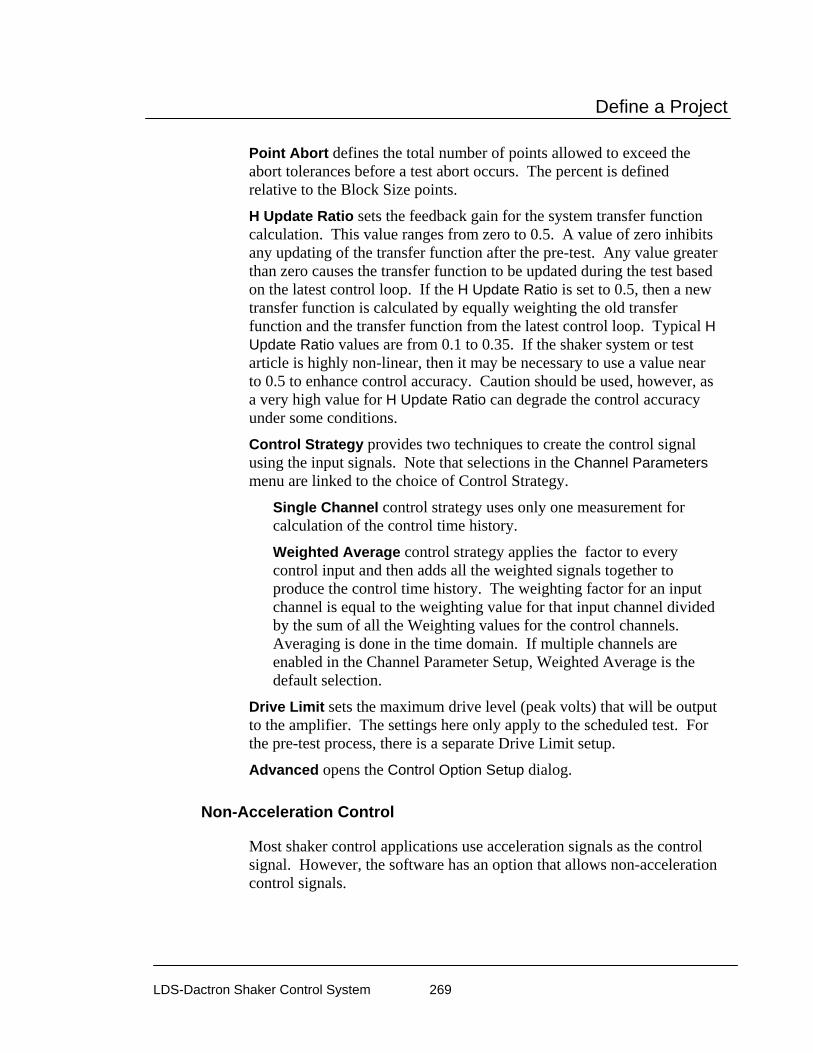
Define a Project
LDS-Dactron Shaker Control System 269
Point Abort defines the total number of points allowed to exceed the abort tolerances before a test abort occurs. The percent is defined relative to the Block Size points.
H Update Ratio sets the feedback gain for the system transfer function calculation. This value ranges from zero to 0.5. A value of zero inhibits any updating of the transfer function after the pre-test. Any value greater than zero causes the transfer function to be updated during the test based on the latest control loop. If the H Update Ratio is set to 0.5, then a new transfer function is calculated by equally weighting the old transfer function and the transfer function from the latest control loop. Typical H Update Ratio values are from 0.1 to 0.35. If the shaker system or test article is highly non-linear, then it may be necessary to use a value near to 0.5 to enhance control accuracy. Caution should be used, however, as a very high value for H Update Ratio can degrade the control accuracy under some conditions.
Control Strategy provides two techniques to create the control signal using the input signals. Note that selections in the Channel Parameters menu are linked to the choice of Control Strategy.
Single Channel control strategy uses only one measurement for calculation of the control time history.
Weighted Average control strategy applies the factor to every control input and then adds all the weighted signals together to produce the control time history. The weighting factor for an input channel is equal to the weighting value for that input channel divided by the sum of all the Weighting values for the control channels. Averaging is done in the time domain. If multiple channels are enabled in the Channel Parameter Setup, Weighted Average is the default selection.
Drive Limit sets the maximum drive level (peak volts) that will be output to the amplifier. The settings here only apply to the scheduled test. For the pre-test process, there is a separate Drive Limit setup.
Advanced opens the Control Option Setup dialog.
Non-Acceleration Control
Most shaker control applications use acceleration signals as the control signal. However, the software has an option that allows non-acceleration control signals.
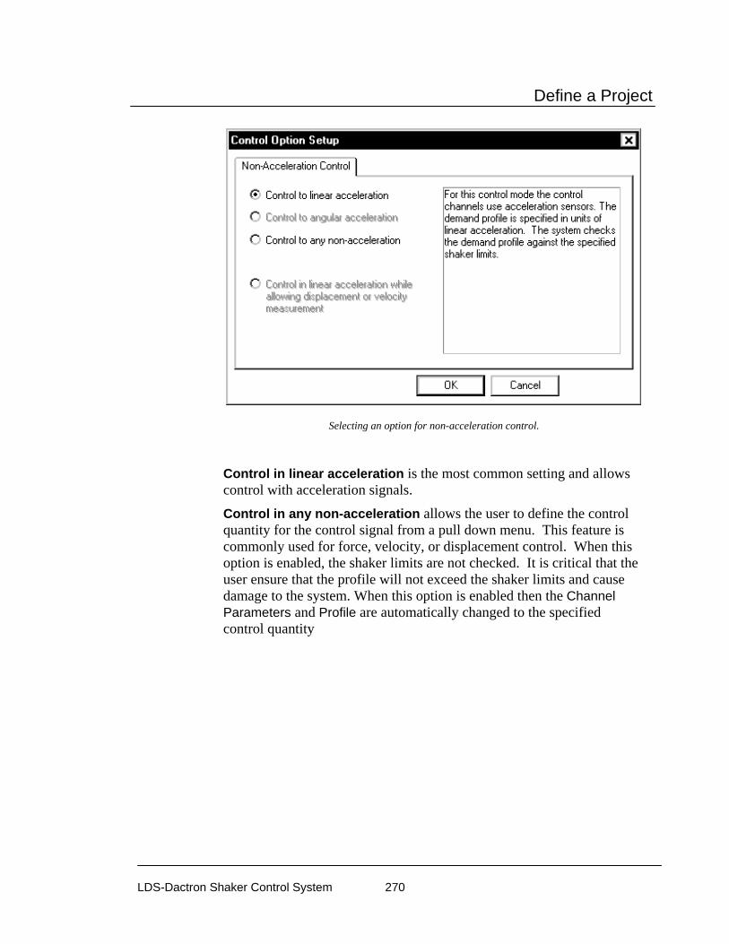
Define a Project
LDS-Dactron Shaker Control System 270
Selecting an option for non-acceleration control.
Control in linear acceleration is the most common setting and allows control with acceleration signals.
Control in any non-acceleration allows the user to define the control quantity for the control signal from a pull down menu. This feature is commonly used for force, velocity, or displacement control. When this option is enabled, the shaker limits are not checked. It is critical that the user ensure that the profile will not exceed the shaker limits and cause damage to the system. When this option is enabled then the Channel Parameters and Profile are automatically changed to the specified control quantity

Define a Project
LDS-Dactron Shaker Control System 271
If non-acceleration control is selected, then you must specify the type of sensor to be used for control.
Pre-Test Page for LTH Control Parameters
The Pre-Test page defines the parameters for the initial equalization operations that occur prior to starting a full-level test. Method of Acquiring the Loop Frequency Response Function (FRF) section is used select one of the following schemes:
Measure during Pre-Test is the preferred method of achieving the FRF that will be used during the scheduled test.
Use Current Active Function and Skip Pre-Test is used only when the test has just been run successfully and nothing else has changed. Use this function only when extreme care has been taken to ensure that the test is being repeated with no changes at all from the last time it was run. A change of just a few hours of test-time is sometimes enough to have a significant effect on the running of a test.
Recall Function from Disk and Skip Pre-Test is used when you are absolutely sure that the FRF stored on disk is exactly the same as the current conditions. Use this selection only with extreme care.
If the Block Size is changed, the Current Active Transfer Function and the Transfer Function Saved to Disk may still be valid for use because the control software interpolates to derive a new transfer function. A

Define a Project
LDS-Dactron Shaker Control System 272
warning message will be shown if this happens. Be cautious when you take advantage of this Control Parameters feature because if you use an old transfer function with less resolution, the initial start-up process might be inappropriate.
Pre-Test Parameters for LTH
Initial Drive sets the drive voltage at which the signal amplitude will start. Use a very low setting (such as 0.005 volts) if you have no knowledge of the shaker system characteristics. For hydraulic shakers, set this value higher (such as 0.5 volts) to overcome the non-linearity of the hydraulic system.
Ramp-up Rate sets the speed with which the amplitude is going to increase. Take into consideration the response time of your entire shaker system for this setting. Avoid “Shocking” the system. A shock to the system would involve a ramp-up speed that exceeds the ability of the shaker system to respond to dynamic changes. Generally, Fast Ramp-up works well with linear systems such as electrodynamic shaker systems. For hydraulic shaker systems, which are very non-linear, the best choice is Slow Ramp-up.
Response Level Goal is the desired amplitude level that must be achieved for the test to pass the pre-test check. If this level is not achieved, the test will not run. This allows you to troubleshoot a potential problem before it affects the UUT or the shaker system.

Define a Project
LDS-Dactron Shaker Control System 273
Typical values for this selection range from 10% to 50%. Once the Response Level Goal is reached, the control system will retain the system transfer function and use it in the scheduled test.
Maximum Drive is the maximum limit (peak volts) of the drive channel during the pre-test.
Skip Pre-Test Report and Start Scheduled Test provides the option to bypass the pre-test report, displayed after completion of the pre-test, and immediately start the Run Schedule. If this option is not selected (not checked), then the pre-test report is displayed and the operator must give a Proceed command to start the Run Schedule. Note that the normal pre-test safety check remain active regardless of the selection here. If there is an open-loop condition, if the maximum drive voltage is reached, or the desired response goal level is not achieved, then the pre-test will abort. Usually this selection is active (checked) when the Digital I/O and Project Sequence functions are used.
Preferences for LTH
Controls Page for LTH Preferences
The Controls page of the Preferences dialog box programs the rate of change of the drive signal during a test shutdown or during a level change in the pre-test or test. It also allows you to pre-program the incremental change to the drive signal using manual level control.
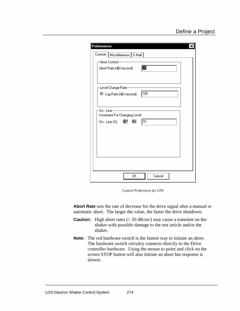
Define a Project
LDS-Dactron Shaker Control System 274
Control Preferences for LTH
Abort Rate sets the rate of decrease for the drive signal after a manual or automatic abort. The larger the value, the faster the drive shutdown.
Caution: High abort rates (> 20 dB/sec) may cause a transient on the shaker with possible damage to the test article and/or the shaker.
Note: The red hardware switch is the fastest way to initiate an abort. The hardware switch circuitry connects directly to the Drive controller hardware. Using the mouse to point and click on the screen STOP button will also initiate an abort but response is slower.

Define a Project
LDS-Dactron Shaker Control System 275
LTH Profile The Profile menu enables setting up both the Pre-Test Profile and the Waveform Profile. Selecting Waveform Profile invokes the Profile Schedule dialog. The Profile Event option allows you to define a single waveform profile or multiple waveforms to be used for an automatically sequenced schedule of tests. The Profile Schedule option will be discussed in more detail in the section titled “LTH Profile Schedule”.
LTH Pre-Test Profile
The LTH Pre-Test Profile dialog consists of two Pages: Plot and Table.
Plot Page for LTH Pre-Test Profile The Plot page displays the project Profile. The Profile can be changed on the Table Page.

Define a Project
LDS-Dactron Shaker Control System 276
LTH Pre-Test Profile Plot Page
Table Page for LTH Pre-Test Profile The Table page allows you to enter the profile breakpoints and describe the resulting spectrum. The table functions like a spreadsheet.
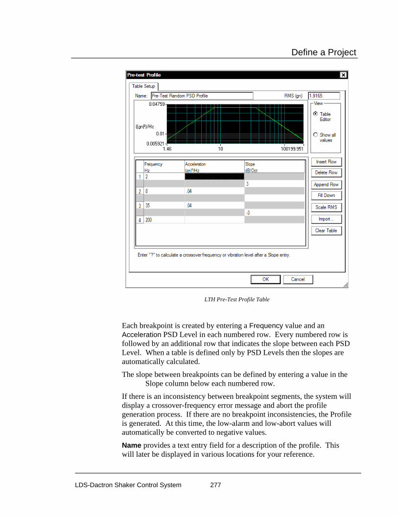
Define a Project
LDS-Dactron Shaker Control System 277
LTH Pre-Test Profile Table
Each breakpoint is created by entering a Frequency value and an Acceleration PSD Level in each numbered row. Every numbered row is followed by an additional row that indicates the slope between each PSD Level. When a table is defined only by PSD Levels then the slopes are automatically calculated.
The slope between breakpoints can be defined by entering a value in the Slope column below each numbered row.
If there is an inconsistency between breakpoint segments, the system will display a crossover-frequency error message and abort the profile generation process. If there are no breakpoint inconsistencies, the Profile is generated. At this time, the low-alarm and low-abort values will automatically be converted to negative values.
Name provides a text entry field for a description of the profile. This will later be displayed in various locations for your reference.
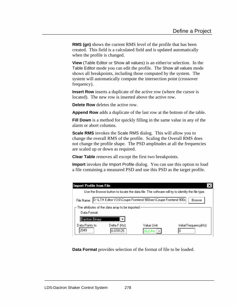
Define a Project
LDS-Dactron Shaker Control System 278
RMS (gn) shows the current RMS level of the profile that has been created. This field is a calculated field and is updated automatically when the profile is changed.
View (Table Editor or Show all values) is an either/or selection. In the Table Editor mode you can edit the profile. The Show all values mode shows all breakpoints, including those computed by the system. The system will automatically compute the intersection point (crossover frequency).
Insert Row inserts a duplicate of the active row (where the cursor is located). The new row is inserted above the active row.
Delete Row deletes the active row.
Append Row adds a duplicate of the last row at the bottom of the table.
Fill Down is a method for quickly filling in the same value in any of the alarm or abort columns.
Scale RMS invokes the Scale RMS dialog. This will allow you to change the overall RMS of the profile. Scaling the Overall RMS does not change the profile shape. The PSD amplitudes at all the frequencies are scaled up or down as required.
Clear Table removes all except the first two breakpoints.
Import invokes the Import Profile dialog. You can use this option to load a file containing a measured PSD and use this PSD as the target profile.
Data Format provides selection of the format of file to be loaded.

Define a Project
LDS-Dactron Shaker Control System 279
LDS-Dactron Binary is the system’s default data import and export format. This format preserves all the information about the data including measurement parameters. This compact file format also minimizes the disk space required to save signal data.
LDS-Dactron ASCII Delimited files include minimal header information such as the frame size, the sampling rate, etc., written in ASCII Format. Note that there are two types of LDS-Dactron ASCII Delimited data formats: (1) Y-data only or (2) X-Y pair.
ASCII Delimited Format includes other types of ASCII delimited formats. In this case, you have to input some of the necessary information after you have loaded the file. If the data is X-Y pair format then only the Y-value units need to be specified. For Y-value only, the PSD frequency resolution Delta F, the Y-value unit of the data to be imported, and the initial frequency value need to be specified.
UFF Text and UFF Binary are popular industry formats. In LTH, only auto-spectrum UFF signals can be recognized and imported.
Note: MTS ATI/AFU and RPCIII formats are only available on Windows 2000 operating system and are not available in others. Shaker Control is not able to recognize MTS ATI/AFU files set with a “Read-only” attribute as defined in the MTS library. Please ensure prior to attempting to recall MTS ATI/AFU files in Shaker Control that the "Read-only" attribute has been disabled for these files.
MTS ATI Format is a binary file used with IDEAS software.
MTS AFU Format is a binary file used with MTS Noise Path Analysis software.

Define a Project
LDS-Dactron Shaker Control System 280
Agilent SDF Format is a binary data file that is an open format used with many Agilent and HP devices. The structure is published and maintained by Agilent.
Note: When importing ASCII data it is assumed that commas are used to designate thousands and other large denominations. If periods are used, the data must be reformatted with commas used instead of periods. For example, the number four thousand, seven hundred twenty eight, and 98/100, if represented using a period format would be 4.728.98. For the application program to correctly read this value it must be formatted as 4,728.98.
Refresh redraws the profile display at the top of the page.
Waveform Profile for LTH LTH allows you to import a waveform recorded in the field, make necessary changes such as displacement compensation or scaling, and then replicate the waveform on the shaker.
Creation of a LTH waveform profile involves two steps. First the waveform is imported and compensated. This is done in the Waveform Editor. This editor is a stand-alone program that can be run concurrently with the LTH Shaker Control software. Waveform Editor can be started from the desktop icon or using the Programs selection under Windows Start.
The second step to creating a profile is to import the waveform generated in the Waveform editor program. This step is performed in the LTH Shaker Control software under the Profile menu.

Define a Project
LDS-Dactron Shaker Control System 281
Overview of LTH Waveform Profile Definition
Waveform Editor The Waveform Editor provides the tools necessary to import a waveform or create a waveform from a mathematical model.
A project management structure is used for Waveform Editor as it is for the shaker control applications. The operations to save or open a project are the same.
Once you have opened theWaveform Editor application the following menu bar and tool bar will be displayed.
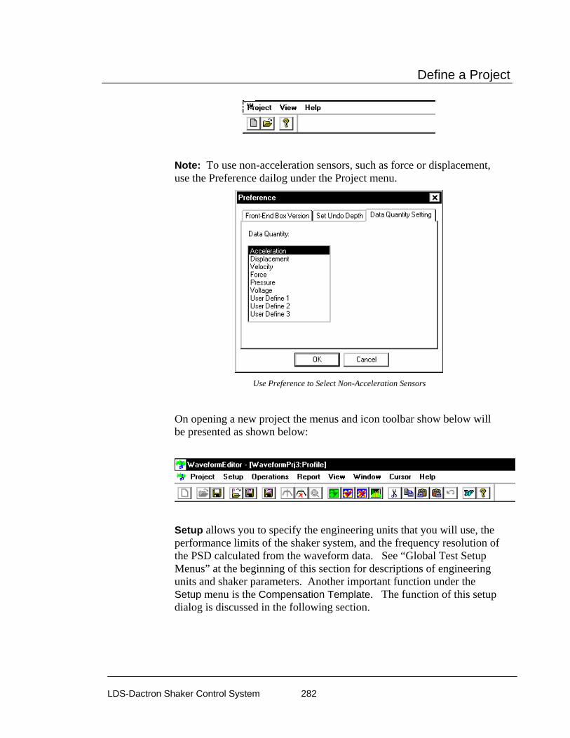
Define a Project
LDS-Dactron Shaker Control System 282
Note: To use non-acceleration sensors, such as force or displacement, use the Preference dailog under the Project menu.
Use Preference to Select Non-Acceleration Sensors
On opening a new project the menus and icon toolbar show below will be presented as shown below:
Setup allows you to specify the engineering units that you will use, the performance limits of the shaker system, and the frequency resolution of the PSD calculated from the waveform data. See “Global Test Setup Menus” at the beginning of this section for descriptions of engineering units and shaker parameters. Another important function under the Setup menu is the Compensation Template. The function of this setup dialog is discussed in the following section.

Define a Project
LDS-Dactron Shaker Control System 283
Profile Compensation
The Compensation Template dialog provides tools to compensate the profile waveform so that the velocity and displacements waveforms are within the capabilities of the shaker system. This dialog also allows you to digitally apply a high-pass and low-pass filters as well.
A number of compensation operations can be defined and applied sequentially, in one operation. It is also possible to apply the compensation operations automatically when a new profile waveform is loaded from a disk file.
The Compensation Template allows for a sequence of
compensation operations to be applied in one operation.
Clicking on the Insert button invokes the Compensation dialog. The drop-down menu provides a number of choices for the compensation method.

Define a Project
LDS-Dactron Shaker Control System 284
Waveform Profile Compensation Options
Acc. DC (Vel. Slope) Remove subtracts the DC component in the acceleration waveform. This removes a slope trend from the velocity waveform. This method is useful for the raw data with offset measurement error. This is usally the case during the data acquisition.
Vel. DC (Disp. Slope) Remove subtracts the DC component in the velocity waveform. This removes a slope trend from the displacement waveform. This method is useful when acceleration discountinuities are present. An acceleration discountinouity (a sharp spike in acceleration) will generate an offset in the velocity profile which then results in a slope in the displacement.
Vel. DC (Disp. Slope) Remove (block by block) subtracts the DC component in the velocity waveform one block of data at a time. This removes a slope trend from the displacement waveform. It should be used for a large waveforms that may have a DC offset that varies slowly with time. Note that this compensation may have to applied many times (anywhere from 20 to 100 times) to get the best result. Use the Repeat entry field to define the number of times to automatically apply this compensation.
High Pass Filter suppresses low-frequency signals below the specified cutoff frequency. This method is very effective to all types of signals with large displacements but has a disadvantge in removing certain amounts of low frequency energy. The cutoff frequency should be set as low as possible while still maintaining the displacement requirement.
Low Pass Filter suppresses high-frequency signals above the specified cutoff frequency. Note that this method does not have a major impact on the displacement or velocity profile. This method is useful in that it will help to remove high-frequency components that the user does not want the shaker to duplicate or the shaker is incapable of duplicating.

Define a Project
LDS-Dactron Shaker Control System 285
At the bottom of the Compensation Template dialog there is an option to the Apply compensation template automatically when waveform is imported. This option, when checked, causes the compensation operations defined by the compensation template to be applied to each waveform as it is imported from disk.
Operations for Importing, Creating and Editing Waveforms
The Operations menu is used to import a waveform or create one from a math model, manipulate the waveform, and save created waveforms and their associated PSD functions.
Import Profile from File reads in a waveform from disk. This function is described in detail in the next section.
Create Profile From Math Model generates a waveform using analytical models. This function is described in detail later on in this section.
Copy, Delete, Paste to Left, Paste to Right are graphical editing tools that can be applied to the profile waveform. This function is described in detail later on in this section.
Rescale allows the user to enter a Rescale Factor that modifies the waveform values to change the amplitude of the profile.
Decimation deletes every other point to reduce the total point size of the profile waveform. This method should always be preceded by digital

Define a Project
LDS-Dactron Shaker Control System 286
low-pass filtering with the cutoff frequency set to be one-quarter or less of the current sampling frequency.
Apply Compensation uses the compensation operations defined by the Compensation Template in a single operation.
Importing a Profile Waveform from a Disk File To import a time history waveform as the profile, either click on the Import Profile icon on the icon toolbar or go to the Operations menu and click on the Import Profile from File selection.
LTH Import Profile from File Dialog to load a waveform from a disk file
Use the File Name field, or the Browse button, to enter the file name for the data to be imported. Once the Open command is given, Waveform Editor will automatically identify the data format and then import the data from the disk file.
LTH imports the following types of the data:
LDS-Dactron Binary is the system’s default data import and export format. This format preserves all the information about the data

Define a Project
LDS-Dactron Shaker Control System 287
including measurement parameters. This compact file format also minimizes the disk space required to save signal data.
LDS-Dactron ASCII Delimited files include minimal header information such as the frame size, the sampling rate, etc., written in ASCII Format. Note that there are two types of LDS-Dactron ASCII Delimited data formats: (1) Y-data only or (2) X-Y pair.
ASCII Delimited Format includes other types of ASCII delimited formats. In this case, you have to input some of the necessary information. User-supplied information includes whether the data is Y-value only or in X-Y pair, the sampling rate, and the size of the data frame to be imported.
LTH Profile is the format most commonly used with LTH
UFF is a popular industry format. In LTH, only time domain UFF signals can be recognized and imported.
WAV Audio format is a digital audio file that can be played back using a digital audio player or PC. Note waveform amplitude is not preserved in the WAV format and WAV files cannot be recalled into LDS-Dactron software.
Agilent SDF Format (Standard Data Format) is a binary data file that is an open format used with many Agilent and HP devices. The structure is published and maintained by Agilent.
Note: MTS ATI/AFU and RPCIII formats are only available on Windows 2000 operating system and are not available in others. Shaker Control is not able to recognize MTS ATI/AFU files set with a “Read-only” attribute as defined in the MTS library. Please ensure prior to attempting to recall MTS ATI/AFU files in Shaker Control that the "Read-only" attribute has been disabled for these files.
MTS ATI format is a binary file used with IDEAS software.
MTS AFU format is a binary file used with MTS Noise Path Analysis software.
MTS RPCIII format is a binary file used with MTS Remote Parameter Control Simulation Testing, Analysis, and Control System software.
Note1: Strip all header information from the ASCII Delimited file and save as a new file. Waveform Editor will not be able to import the waveform data if the header is included with the file.

Define a Project
LDS-Dactron Shaker Control System 288
Note2: When importing ASCII data it is assumed that commas are used to designate thousands and other large denominations. If periods are used, the data must be reformatted with commas used instead of periods. For example, the number four thousand, seven hundred twenty eight, and 98/100, if represented using a period format would be 4.728.98. For the application program to correctly read this value it must be formatted as 4,728.98.
Once the data file has been imported, you need to specify a few parameters before pressing the OK button.
LTH Import Profile from File dialog after opening a data file
Delta T (ms) specifies the sampling rate used for the imported data.
Value Unit defines the engineering units used for the imported data.
Compensation enables automatic application of the current Compensation Template setup to the imported waveform. The Setting button allows the compensation template to be modified.
After Digital Resampling allows you to set sampling rate different than the original sampling rate. If the digital resampling is set for Auto, the program will determine the best sampling rate to use. If the waveform

Define a Project
LDS-Dactron Shaker Control System 289
sampling rate exactly matches an available sampling rate of the LDS-Dactron system, digital re-sampling is not required. This is always the case if the data was recorded with the LDS-Dactron system. However, if the imported data has a different sampling rate, digital re-sampling is required to prevent distortion of the waveform shape during output. Generally you should select Auto for the Sampling Freq(Hz) field.
Digital re-sampling is done internally by a 5th order filter. This high-order filter ensures against the loss of signal information in the sampling bandwidth during re-sampling. Be aware that if you choose to digitally re-sample the data at lower rate than that used to acquire the data, signal aliasing may occur. A better method is to use the digital low-pass filter and decimate options under Profile Compensation.
Import Method controls how the imported waveform is used in together with the existing profile waveform. Replace initializes the waveform buffer and loads in the waveform just imported. Append adds the waveform just imported to the existing profile. From/At position specifies the data point in the profile buffer to begin insertion of the new waveform segment.
Creating the Profile Waveform from a Mathematical Model LTH offers classical waveforms such as sine, chirp (a fast swept sine) or random as templates for the profile waveform. Click on Create Profile from Math Model to invoke the following dialog:
LTH Dialog to Create a Profile from a Math Model Library

Define a Project
LDS-Dactron Shaker Control System 290
Note that the choices available in this dialog box will depend on the selection made in the Waveform Type menu.
Waveform Type includes the following math models to use as independent profiles or as blocks for a profile synthesized from imported waveforms and math model waveforms:
White Noise is a broadband random signal with uniform energy across the frequency band.
Sine allows generation of a constant frequency sine wave.
Chirp provides a fast sine sweep with the initial and final frequency user specified.
Band-Limited Random is a random signal with uniform energy across a specified frequency band.
Graphical Editing Operations
There are a number of editing options for on-screen manipulation of imported waveforms. These operations allow “cleaning up” of the waveform by deleting unwanted data segments or changing the sequence of events in a waveform.
Copy and Delete Selection After you have selected an interval from the waveform using two cursors, the Copy and Cut functions become available to you from the Edit menu or by using their respective icons [ Copy & Cut]. These functions allow you to copy the selected interval to the clipboard for pasting or simply to delete the selection from the overall waveform. Note that Copy and Cut functions apply only to the Profile Window.

Define a Project
LDS-Dactron Shaker Control System 291
When you add two cursors , you can move the cursors in the pane in order to select the desired interval. Information concerning this interval is displayed on overlaid the table. Furthermore, the interval you select will have a yellow background.
Select an Interval Using 2 Cursors
• Copy copies the selected waveform interval to the clipboard.
• Cut deletes the selected waveform interval from the entire waveform and combines the side to the left and the side to the right of the deleted interval together. Before, the delete is performed you will be prompted with the following warning message.
• Undo Goes back one step and undoes the last action performed.
Paste Selection The Paste function allows you to paste a waveform interval that was previously copied into the clipboard to a new location on the
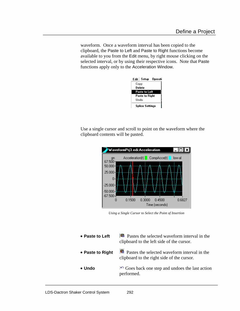
Define a Project
LDS-Dactron Shaker Control System 292
waveform. Once a waveform interval has been copied to the clipboard, the Paste to Left and Paste to Right functions become available to you from the Edit menu, by right mouse clicking on the selected interval, or by using their respective icons. Note that Paste functions apply only to the Acceleration Window.
Use a single cursor and scroll to point on the waveform where the clipboard contents will be pasted.
Using a Single Cursor to Select the Point of Insertion
• Paste to Left Pastes the selected waveform interval in the clipboard to the left side of the cursor.
• Paste to Right Pastes the selected waveform interval in the clipboard to the right side of the cursor.
• Undo Goes back one step and undoes the last action performed.

Define a Project
LDS-Dactron Shaker Control System 293
Splice Operations
The Splice operation is used to minimize boundary discontinuity when two pieces of data are put together. Once enabled, the chosen Data Window will be applied to the data array at both ends for the following cases:
1) When a piece of data is appended to the previous segment during the file import process.
2) When a piece of data is inserted or pasted into the existing segment
Splice Settings To enable the Splice operation, enter the Splice Settings dialog using either the toolbar icon or by going through the Edit menu.
In the Splice Settings dialog you will be able to define the following: Data Window, Overlapping, and Number of Windowing Points.
Splice Settings Dialog

Define a Project
LDS-Dactron Shaker Control System 294
Data Window The user can choose different Data Window types to be used in the Splice operation.
• None Disables the Splice function
• Hanning Uses a Hanning window during the Splice operation.
• Triangle Uses a Triangular window during the Splice operation
• Half Sine Uses Half Sine window during the Splice operation
Overlapping
• With Overlapping Two pieces of data will be put together with Data Window overlapping. Note that the total length of the profile will be reduced after splicing.
• No Overlapping Data Windows are not overlapped. The length of the profile will not be altered.
Number of Windowing Points The Number of Windowing Points allows you to define the length of the Data Window by number of points. Typically, the Number of Windowing Points is more than 128.

Define a Project
LDS-Dactron Shaker Control System 295
Waveform Editor Application Window
Waveform Editor provides displays for simultaneous viewing of acceleration, velocity, and displacement waveforms and the PSD of the acceleration waveform. The original, uncompensated, the compensated waveforms may be overlaid. Also the shaker tolerances may be included to verify the acceptability of the profile for use on the shaker system.
Waveform Editor Application Window showing Compensated and Orginal Waveforms and PSD Functions
Saving LTH Profile Waveforms and PSD Functions The compensated acceleration waveform and the PSD of this waveform may be saved to disk and then loaded into the LTH Shaker Control application to perform a test. The option to save the profile, and its PSD, are found under the Operations menu.

Define a Project
LDS-Dactron Shaker Control System 296
Save Profile
The acceleration waveform is saved the file extension “.pro” and it may be saved either in a Waveform Editor project folder or in a LTH Shaker Control project folder. PSD functions use the “.sig” file extension default. These signal files can easily be imported into LTH Shaker Control for use as a Pre-Test Profile. It is often desired to use the PSD of the waveform profile for the pre-test transfer function measurement as the energy distribution and amplitude levels are the same as for the waveform itself. This consideration is particularly an advantage for use with electro-hydraulic shakers or non-linear test articles.
Saving an Acceleration Waveform from the Waveform Editor Program
Save Profile in ASCII delimited Format
If the profile is saved as an ASCII file the units are always SI (m/sec^2 for acceleration).
Examples of LTH Profile Compensation
Low-pass Filtering and Decimation
It often desirable to low-pass filter the waveform profile to suppress noise or to delete higher-frequency content that is outside of the frequency range of interest. Decimation allows the profile’s total sample

Define a Project
LDS-Dactron Shaker Control System 297
size to be reduced and it is required if the waveform exceeds the memory limitations of the software. As an example, a recorded waveform is imported as the profile. This waveform contains energy up to 320 Hz. However, the maximum frequency of interest is only 50 Hz. The figure below shows the waveform and its PSD.
Acceleration Time History and PSD for an Imported Wavefrom with Energy Content Up to 320 Hz.
First, a 50 Hz low-pass filter is applied by using the Compensation Template dialog under the Setup menu. After the low pass filter operation has been defined in the Compensation Template, then go to the Operations menu and select Apply Compensation.
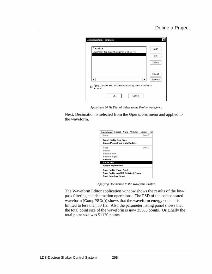
Define a Project
LDS-Dactron Shaker Control System 298
Applying a 50 Hz Digital Filter to the Profile Waveform.
Next, Decimation is selected from the Operations menu and applied to the waveform.
Applying Decimation to the Waveform Profile
The Waveform Editor application window shows the results of the low-pass filtering and decimation operations. The PSD of the compensated waveform (CompPSD(f)) shows that the waveform energy content is limited to less than 50 Hz. Also the parameter listing panel shows that the total point size of the waveform is now 25585 points. Originally the total point size was 51170 points.
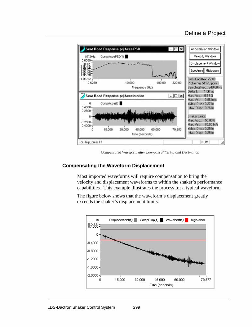
Define a Project
LDS-Dactron Shaker Control System 299
Compensated Waveform after Low-pass Filtering and Decimation
Compensating the Waveform Displacement
Most imported waveforms will require compensation to bring the velocity and displacement waveforms to within the shaker’s performance capabilities. This example illustrates the process for a typical waveform.
The figure below shows that the waveform’s displacement greatly exceeds the shaker’s displacement limits.
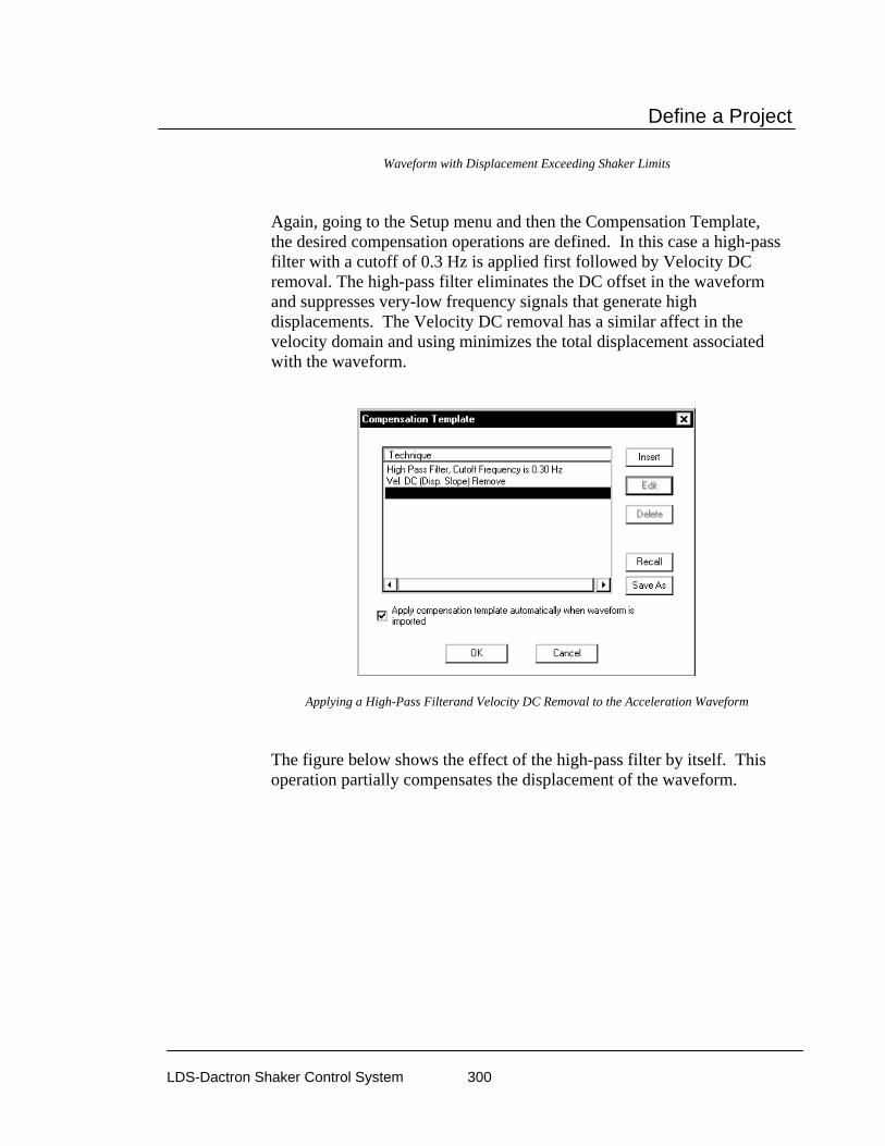
Define a Project
LDS-Dactron Shaker Control System 300
Waveform with Displacement Exceeding Shaker Limits
Again, going to the Setup menu and then the Compensation Template, the desired compensation operations are defined. In this case a high-pass filter with a cutoff of 0.3 Hz is applied first followed by Velocity DC removal. The high-pass filter eliminates the DC offset in the waveform and suppresses very-low frequency signals that generate high displacements. The Velocity DC removal has a similar affect in the velocity domain and using minimizes the total displacement associated with the waveform.
Applying a High-Pass Filterand Velocity DC Removal to the Acceleration Waveform
The figure below shows the effect of the high-pass filter by itself. This operation partially compensates the displacement of the waveform.

Define a Project
LDS-Dactron Shaker Control System 301
Displacement for Compensated Acceleration Waveform After High-pass Filtering
The next figure shows the combined effect of the high-pass filter and the Velocity DC Removal. These two compensation steps bring the waveform’s displacement to within the shaker limits.
Waveform Displacement after High-pass Filtering and Velocity DC Removal
LTH Profile and Schedule In LTH the Profile and Schedule functions are combined into one dialog. After a LTH profile is created in the Waveform Editor program it can be imported into the Shaker Control software. Testing with a single profile

Define a Project
LDS-Dactron Shaker Control System 302
or multiple profiles can be programmed in the LTH Profile Schedule Eevent dialog.
LTH Profile Setup
The LTH Profile Schedule dialog provides the function to load a waveform profile, view the profile, name the profile, define the Run Level, as well as the ability to specify the number of times you would like to repeat the profile. To access the LTH Profile Schedule go to the Profile menu, Waveform Profile, or use the Setup icon toolbar Profile icon
.
This dialog is used to load the waveform profile into the LTH program.
Note: The Profile Schedule dialog can be resized by moving the mouse pointer to one of the corners and using the standard Windows resize operation.
The LTH Profile Schedule permits the set up of a test with many waveform profiles automatically run one after the other by having multiple Profile Event entries. The profiles must all be generated by the Waveform Editor program. One further important restriction is that the sampling frequency must be the same for all waveforms. This

Define a Project
LDS-Dactron Shaker Control System 303
requirement is easy to satisfy in the Waveform Editor by using setting the sample interval for the waveform acquired with the highest sampling rate as the digital resampling setting as each waveform is imported into the Waveform Editor.
Profile Event invokes a dialog to load a waveform and specify parameters such as the name, excitation level to use, and the number of times to repeat the test run using this waveform.
The Profile Event is Used toImport a Profile Created in Waveform Editor.
Name allows you specify a desired name for the imported waveform profile file.
Browse invokes an Open window to locate and open the desired waveform profile file. Only waveforms saved from the Waveform Editor program can be used. See the previous section, “Waveform Editor”, for more information on using this program to create waveform profiles.
Profile displays the name and location of the directory that contains the desired waveform profile file you want to load.
Run at Level allows you to define the % of full scale you would like to run the waveform profile at.
Repeat this profile allows you to define the number of times you would like the LTH Profile Schedule to repeat this profile.
The View this Profile button invokes the Long Time History Control Profile dialog as shown below.
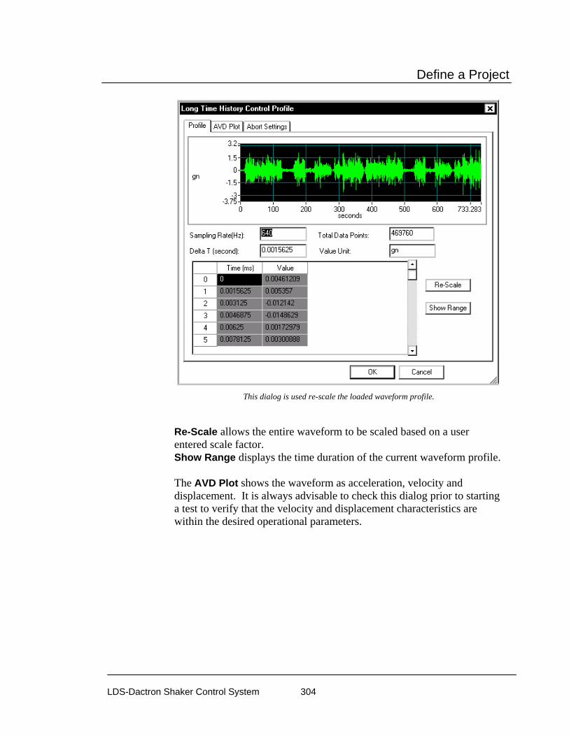
Define a Project
LDS-Dactron Shaker Control System 304
This dialog is used re-scale the loaded waveform profile.
Re-Scale allows the entire waveform to be scaled based on a user entered scale factor. Show Range displays the time duration of the current waveform profile. The AVD Plot shows the waveform as acceleration, velocity and displacement. It is always advisable to check this dialog prior to starting a test to verify that the velocity and displacement characteristics are within the desired operational parameters.

Define a Project
LDS-Dactron Shaker Control System 305
Use the AVD Plot to verify the velocity and displacement characteristics of the waveform profile. The Abort Setting page is used to set the positive and negative acceleration abort levels.

Define a Project
LDS-Dactron Shaker Control System 306
Positive and negative acceleration abort levels are set in the Abort Setting dialog.
Advanced Abort Setup allows the user to set different abort levels at different times during the profile record. Enter the time, abort high and low values in the table. Click Refresh to see the new abort levels in the plot.

Define a Project
LDS-Dactron Shaker Control System 307
Advanced abort limits can change at different times in the profile.
Schedule for LTH
The LTH Profile Schedule also provides automatic programming for the following functions: periodic saving of signal data, report generation, sending Net-Integrator commands, sending Digital Output signals, and defining Chamber Events. The selection list on the left side of the Schedule dialog adds entries for definition of the schedule.
To edit an entry, either double-click it, or highlight it and click the Edit Item button. You may also Delete an item in the list or Edit one that has already been entered.
Start a Loop invokes a dialog to specify the number of times that a loop will be repeated.
End a Loop closes a loop sequence. Loops can be nested but End a Loop and Start a Loop entries must be defined as a pair.
Save Results invokes the following dialog box and lets you specify the signals to save automatically:

Define a Project
LDS-Dactron Shaker Control System 308
Save Results Dialog Box
Quick Report generates a test report within MS Word. This command can be used to automatically generate data plots or test reports at pre-set times or test events.
Net-Integrator Command sends either a Start or Stop command to another application, such as RT-Pro, that is concurrently running.
User Digital Output invokes the following dialog box and lets you specify which of pins 2 – 9 on digital output port two to output a TTL signal.
Programming a TTL output signal via Digital I/O Port 2.
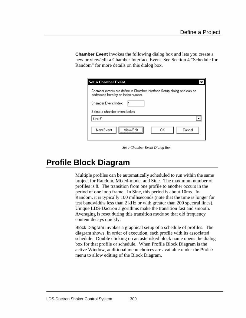
Define a Project
LDS-Dactron Shaker Control System 309
Chamber Event invokes the following dialog box and lets you create a new or view/edit a Chamber Interface Event. See Section 4 “Schedule for Random” for more details on this dialog box.
Set a Chamber Event Dialog Box
Profile Block Diagram Multiple profiles can be automatically scheduled to run within the same project for Random, Mixed-mode, and Sine. The maximum number of profiles is 8. The transition from one profile to another occurs in the period of one loop frame. In Sine, this period is about 10ms. In Random, it is typically 100 milliseconds (note that the time is longer for test bandwidths less than 2 kHz or with greater than 200 spectral lines). Unique LDS-Dactron algorithms make the transition fast and smooth. Averaging is reset during this transition mode so that old frequency content decays quickly.
Block Diagram invokes a graphical setup of a schedule of profiles. The diagram shows, in order of execution, each profile with its associated schedule. Double clicking on an asterisked block name opens the dialog box for that profile or schedule. When Profile Block Diagram is the active Window, additional menu choices are available under the Profile menu to allow editing of the Block Diagram.
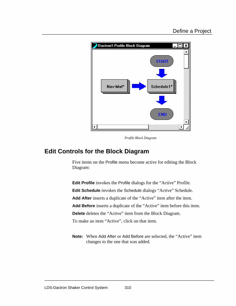
Define a Project
LDS-Dactron Shaker Control System 310
Profile Block Diagram
Edit Controls for the Block Diagram Five items on the Profile menu become active for editing the Block Diagram:
Edit Profile invokes the Profile dialogs for the “Active” Profile.
Edit Schedule invokes the Schedule dialogs “Active” Schedule.
Add After inserts a duplicate of the “Active” item after the item.
Add Before inserts a duplicate of the “Active” item before this item.
Delete deletes the “Active” item from the Block Diagram.
To make an item “Active”, click on that item.
Note: When Add After or Add Before are selected, the “Active” item changes to the one that was added.

Define a Project
LDS-Dactron Shaker Control System 311
Profile Block Diagram with Profile Menu Edit Controls
Project Sequence A Project Sequence provides the capability to automatically execute a sequence of project files. All of the project files may be for the same type of application, such as all random tests, or they may be for a variety of applications. This later type of sequence is referred to as “mission profiling.” For this type of profile sequencing, a random test might be followed by a shock test and then a sine on random test.

Define a Project
LDS-Dactron Shaker Control System 312
To define a sequence of project files select Project Sequence Setup, under the Project menu. This selection only appears in the top-level menu. If you have a project file open, you must first close this project in order to access Project Sequence Setup.
Project Sequence Setup Dialog Box
Repeat this sequence repeats the entire sequence the specified number of times.
Add invokes the file Open dialog box and allows you to select a project file to add to the Project Sequence. The selected project file is inserted in the sequence list on the highlighted line.
Delete removes the highlighted project file from the sequence list.
Save invokes the Save As dialog box to store the Project Sequence list as a disk file.
Import invokes the file Open dialog box to recall a previously stored Project Sequence file (files with extension “.psf “).
To ensure fully automatic, trouble-free operation you should:
• Make sure that you check the Skip Pre-Test Report and Start Scheduled Test selection on the Pre-Test page of Control Parameters for all Projects to be used in the Project Sequence.
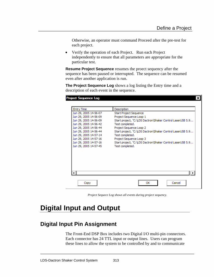
Define a Project
LDS-Dactron Shaker Control System 313
Otherwise, an operator must command Proceed after the pre-test for each project.
• Verify the operation of each Project. Run each Project independently to ensure that all parameters are appropriate for the particular test.
Resume Project Sequence resumes the proect sequency after the sequence has been paused or interrupted. The sequence can be resumed even after another application is run.
The Project Sequence Log shows a log listing the Entry time and a description of each event in the sequence.
Project Sequece Log shows all events during project sequency.
Digital Input and Output
Digital Input Pin Assignment The Front-End DSP Box includes two Digital I/O multi-pin connectors. Each connector has 24 TTL input or output lines. Users can program these lines to allow the system to be controlled by and to communicate

Define a Project
LDS-Dactron Shaker Control System 314
with external controllers, such an environmental chamber. This facilitates fully automatic vibration and environmental stress testing.
Some of the pins of the DIGITAL I/O 1 connector have factory-assigned default settings. Pins 2 to 9 are used exclusively for digital output. Pin 10 and pins 29 to 36 are used exclusively for digital input.
Pin number assignments for DIGITAL I/O 1 are as follows:
Pins 2 to 9 digital output
Pins 11 to 17 reserved for future programming by LDS-Dactron
Pins 29 to 36 digital input
Pins 19 and 21 output a TTL-high level, which is +5Volts (marked as VCC below)
Pins 1, 23, 25, 26, 27, 36 not available
Pins 18, 20, 22, 24, 28 connected to the internal digital ground
1 2 3
20 21 22
4
23
5 6
24
7
25
8
26
9
27
10
28
11
29
12
30 31
13 14
32
15
33
16
34 35 36
18 19
37
17
digital output
digital input
GND VCC GND GND
programmable
GND
GND VCC
VCC = +5VGND = Ground
Digital I/O 1 Pin Assignment
The pins on DIGITAL I/O 2 are assigned as follows:
Pin 2 to 9 user programmable via the Use Digital Output Schedule event command.

Define a Project
LDS-Dactron Shaker Control System 315
Pin10 to 17, 29 to 36 reserved for future programming by LDS-Dactron
Pin 21 outputs a TTL-high level, which is +5Volts (marked as VCC below)
Pin 1, 19, 22 to 28, 37 not available
Pin 18, 28 connected to the internal digital ground
1 2 3
20 21 22
4
23
5 6
24
7
25
8
26
9
27
10
28
11
29
12
30 31
13 14
32
15
33
16
34 35 36
18 19
37
17
programmable
programmable
VCC GND
programmable
GND
VCC = +5VGND = Ground
Digital I/O 2 Pin Assignment
Default Digital Output Signals Pins 2 to 9 of DIGITAL I/O 1 are for digital output. Three standard commands are available with digital output: Ready, Start, and Stop. Whenever the system is in digital I/O mode (active) and it is prepared for a Start command, the Ready command line (line 4) outputs a TTL-High signal. This line goes low on a Start and stays low until after a Stop. After the system returns to a standby state the Ready line goes high again. Start and Stop signals are sent out through pins 2 and 3 as TTL-High signals. When either of these commands is sent, a TTL-High level is output for a duration of about 200 ms. Whenever a command is sent, pin 9 also goes to high as a status change indicator. These output signals are only active when digital I/O mode is active (enabled in the Define Digital Input dialog under the Test Setup menu).
As an indicator that the system is in a remote control mode, pin 8 goes high, and stays high, whenever the Enable digital input function checkbox is checked in the Define Digital Input dialog.
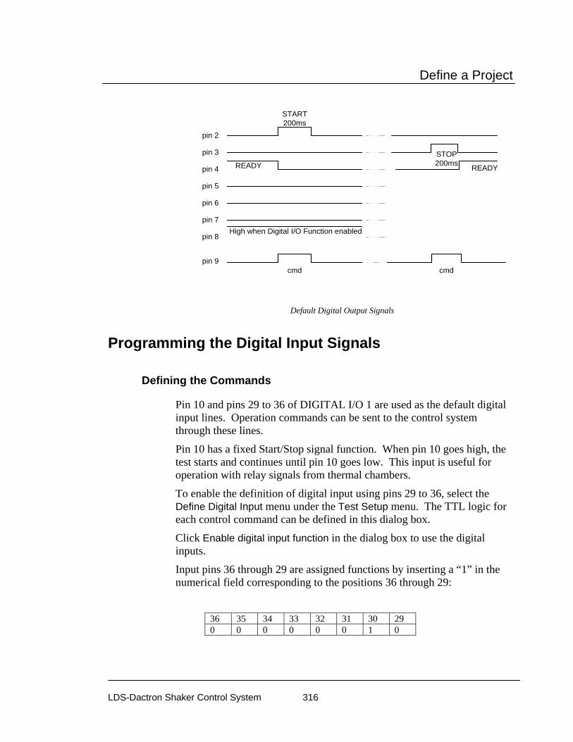
Define a Project
LDS-Dactron Shaker Control System 316
pin 9
pin 2
pin 3
pin 4
pin 5
pin 6
pin 7
pin 8
START200ms
STOP200ms
cmd cmd
READY READY
High when Digital I/O Function enabled
Default Digital Output Signals
Programming the Digital Input Signals
Defining the Commands
Pin 10 and pins 29 to 36 of DIGITAL I/O 1 are used as the default digital input lines. Operation commands can be sent to the control system through these lines.
Pin 10 has a fixed Start/Stop signal function. When pin 10 goes high, the test starts and continues until pin 10 goes low. This input is useful for operation with relay signals from thermal chambers.
To enable the definition of digital input using pins 29 to 36, select the Define Digital Input menu under the Test Setup menu. The TTL logic for each control command can be defined in this dialog box.
Click Enable digital input function in the dialog box to use the digital inputs.
Input pins 36 through 29 are assigned functions by inserting a “1” in the numerical field corresponding to the positions 36 through 29:
36 35 34 33 32 31 30 29 0 0 0 0 0 0 1 0
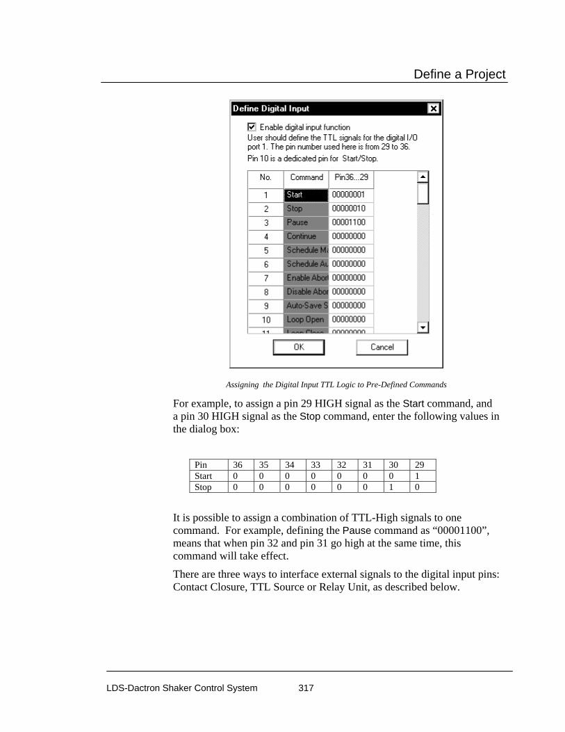
Define a Project
LDS-Dactron Shaker Control System 317
Assigning the Digital Input TTL Logic to Pre-Defined Commands
For example, to assign a pin 29 HIGH signal as the Start command, and a pin 30 HIGH signal as the Stop command, enter the following values in the dialog box:
Pin 36 35 34 33 32 31 30 29 Start 0 0 0 0 0 0 0 1 Stop 0 0 0 0 0 0 1 0
It is possible to assign a combination of TTL-High signals to one command. For example, defining the Pause command as “00001100”, means that when pin 32 and pin 31 go high at the same time, this command will take effect.
There are three ways to interface external signals to the digital input pins: Contact Closure, TTL Source or Relay Unit, as described below.

Define a Project
LDS-Dactron Shaker Control System 318
Required Input Signal Voltage Level and Duration
Nominally, a +5 volt signal is expected as the digital I/O High signal. The allowable voltage level for the digital I/O signals is from +3.6 to +5.5 volts. A High signal is expected to stay high for at least 200 milliseconds.
Warning: Inputs of greater than 5.5 volts can damage the digital I/O hardware.
Wiring and Grounding
Good wiring and grounding practices are necessary to ensure proper and reliable operation of the digital I/O functions. It is important that the Front-End Box and the external equipment share a true common ground. Grounding through the power receptacle is not a good practice. Use a thick wire to connect the ground plug on the back of the Front-End Box chassis to the true common ground. Make sure that the connections to the digital I/O ports are properly grounded. Use a shielded cable for the connection to the digital I/O connectors.
Warning: Use pull-down resistors (10kΩ to 100kΩ) between every input line and the digital ground pin on the DIGITAL I/O 1 connector. This prevents unreliable operation due to floating voltage signals.
Interfacing to a Contact Closure
A contact closure is simply a switch that can turn on or off. By using the VCC (+5Volts) and the digital ground output, you can use the contact closure unit to send digital signals to the system.
The high-impedance of the pin lines require a 10kΩ to 100kΩ resistor connecting the pin line used with the digital ground. This arrangement ensures that the TTL-Low level is the default condition.
To use the contact closure to send the Stop command: First assign one of the pins to this command, say pin 30. Then connect pin 30, pin 28 (ground), pin 21 (VCC) and the contact closure as shown in the following picture:

Define a Project
LDS-Dactron Shaker Control System 319
1 2 3
20 21 22
4
23
5 6
24
7
25
8
26
9
27
10
28
11
29
12
30 31
13 14
32
15
33
16
34 35 36
18 19
37
17
digital output
digital input
GND VCC GND GND
programmable
GND
GND VCC
VCC = +5VGND = Ground
Contact Closure
10-100kΩ
Interface to a Contact Closure
When the contact closes, pin 30 will go high and the control system will detect the signal.
Interfacing to a TTL Source
Some devices have digital TTL Level outputs that can be directly interfaced to the digital input connector of the control system. In this case, simply connect the corresponding TTL lines together. Also be sure to connect the digital grounds of the two devices together.
Assume, for example, that you want to input a TTL-High signal to initiate the Stop command. The first step is to assign one of the pins (let’s say pin 30) to this command. Next, connect pin 30, pin 28 (ground) and the TTL source from the external device as shown in the following graphic:

Define a Project
LDS-Dactron Shaker Control System 320
1 2 3
20 21 22
4
23
5 6
24
7
25
8
26
9
27
10
28
11
29
12
30 31
13 14
32
15
33
16
34 35 36
18 19
37
17
digital output
digital input
GND VCC GND GND
programmable
GND
GND VCC
VCC = +5VGND = Ground
External Device
digital ground
TTL source
10kΩ - 100kΩ
Interface to a TTL Circuit
When pin 30 receives a TTL-high signal, the control system detects the signal and executes the assigned command.
This scheme assumes that the default state of the external TTL source is TTL-Low (0.0 Volt). If this is not the case, a resistor must be used to assert a low default state.
Interfacing to a Relay Unit
A relay is an electromagnetic device activated by induction from another electrical circuit. The relay controls a larger current source or actuates other devices. A relay unit consists of a power source and a switch. Assume that the default condition of the switch is open (off). When activated, the relay switch is closed momentarily.
Again, assume you want to use the relay to initiate the Stop command. First, assign one of the pins to be this command, say pin 30. Then
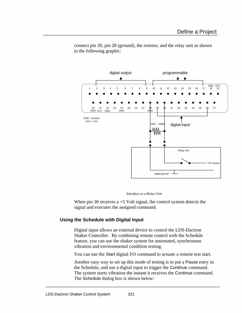
Define a Project
LDS-Dactron Shaker Control System 321
connect pin 30, pin 28 (ground), the resistor, and the relay unit as shown in the following graphic:
1 2 3
20 21 22
4
23
5 6
24
7
25
8
26
9
27
10
28
11
29
12
30 31
13 14
32
15
33
16
34 35 36
18 19
37
17
digital output
digital input
GND VCC GND GND
programmable
GND
GND VCC
VCC = +5VGND = Ground
Relay Unit
digital ground
+5V source
10kΩ - 100kΩ
Interface to a Relay Unit
When pin 30 receives a +5 Volt signal, the control system detects the signal and executes the assigned command.
Using the Schedule with Digital Input
Digital input allows an external device to control the LDS-Dactron Shaker Controller. By combining remote control with the Schedule feature, you can use the shaker system for automated, synchronous vibration and environmental condition testing.
You can use the Start digital I/O command to actuate a remote test start.
Another easy way to set up this mode of testing is to put a Pause entry in the Schedule, and use a digital input to trigger the Continue command. The system starts vibration the instant it receives the Continue command. The Schedule dialog box is shown below:
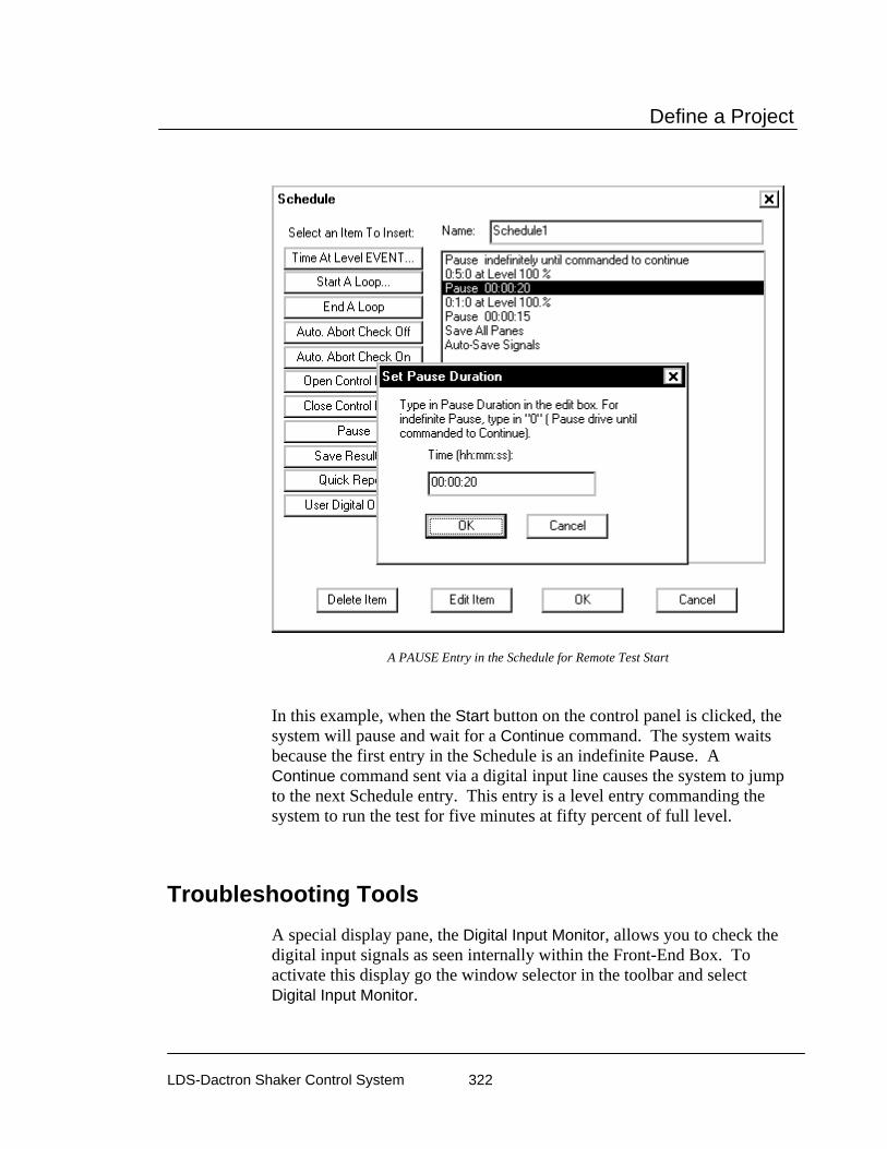
Define a Project
LDS-Dactron Shaker Control System 322
A PAUSE Entry in the Schedule for Remote Test Start
In this example, when the Start button on the control panel is clicked, the system will pause and wait for a Continue command. The system waits because the first entry in the Schedule is an indefinite Pause. A Continue command sent via a digital input line causes the system to jump to the next Schedule entry. This entry is a level entry commanding the system to run the test for five minutes at fifty percent of full level.
Troubleshooting Tools A special display pane, the Digital Input Monitor, allows you to check the digital input signals as seen internally within the Front-End Box. To activate this display go the window selector in the toolbar and select Digital Input Monitor.

Define a Project
LDS-Dactron Shaker Control System 323
Digital inputs signals viewed via the Digital Input Monitor Pane
This special display shows the digital input signals, registered as zero or one values, over time. It is a useful tool for troubleshooting the digital input signal connections and timing. This tool is available for use during either the Test mode or the Preview test mode. Preview, a special test mode, is described in the next section, “Run a Profile”, under “Global Test and Control Menus.”

Run a Project
LDS-Dactron Shaker Control System 324
5 Run a Project This section explains how to run a Project. It also explains what happens when each of the controls is invoked. There are three primary control menus for running a test: the Test menu, the Controls menu and the Control Panel. In addition to these menus, keyboard commands will also be covered. See Section 7, “Tool Bar and Mouse Controls”, for descriptions of icon commands.
Control Panel
The Control Panel provides you with live information pertaining to your test such as: Control, Demand, Level, Drive, and Time information. In addition, the Control Panel gives you direct control to many important test actions such as Start, Stop, and Pause.

Run a Project
LDS-Dactron Shaker Control System 325
Overview of the Run Process
Run Steps and Modes Each run consists of two phases, the pre-test and the test.
Pre-Test
The system first performs safety checks. Then it gradually increases the drive according to the pre-specified peak drive voltage (initial and maximum), response level goal, and ramp-up rate (slow or fast). Once the system successfully equalizes the UUT at the specified “goal” level, the system either immediately executes the run schedule or it pauses for operator approval before continuing. The setting for the Skip Pre-Test Report and Start Scheduled Test in the Pre-Test page of the Control Parameters menu dictates which action is taken by the system after successful equalization.
If any conditions are encountered during the Pre-Test, such as an open-loop condition, the maximum drive voltage limit is reached, or the system fails to equalize at the goal level, the Pre-Test aborts and reports the error condition causing the abort.
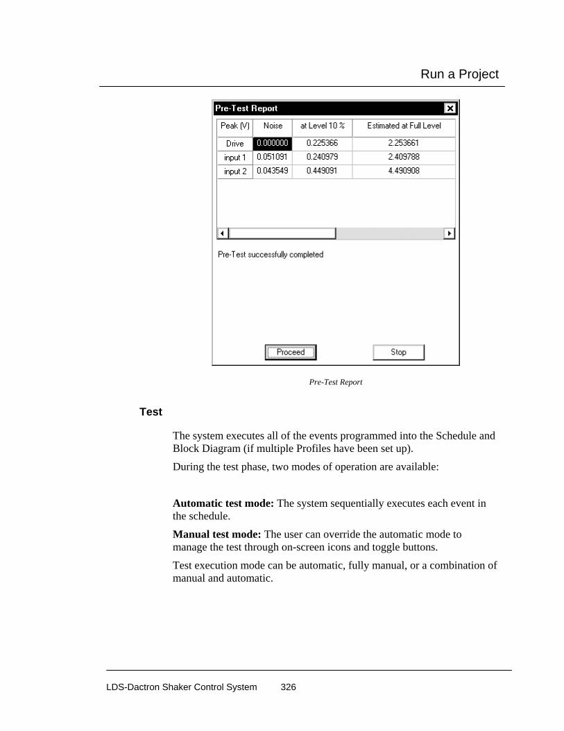
Run a Project
LDS-Dactron Shaker Control System 326
Pre-Test Report
Test
The system executes all of the events programmed into the Schedule and Block Diagram (if multiple Profiles have been set up).
During the test phase, two modes of operation are available:
Automatic test mode: The system sequentially executes each event in the schedule.
Manual test mode: The user can override the automatic mode to manage the test through on-screen icons and toggle buttons.
Test execution mode can be automatic, fully manual, or a combination of manual and automatic.
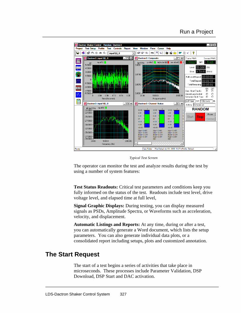
Run a Project
LDS-Dactron Shaker Control System 327
Typical Test Screen
The operator can monitor the test and analyze results during the test by using a number of system features:
Test Status Readouts: Critical test parameters and conditions keep you fully informed on the status of the test. Readouts include test level, drive voltage level, and elapsed time at full level,
Signal Graphic Displays: During testing, you can display measured signals as PSDs, Amplitude Spectra, or Waveforms such as acceleration, velocity, and displacement.
Automatic Listings and Reports: At any time, during or after a test, you can automatically generate a Word document, which lists the setup parameters. You can also generate individual data plots, or a consolidated report including setups, plots and customized annotation.
The Start Request The start of a test begins a series of activities that take place in microseconds. These processes include Parameter Validation, DSP Download, DSP Start and DAC activation.

Run a Project
LDS-Dactron Shaker Control System 328
Parameter Validation
As soon as the Start command is received, three validation processes start in sequence. The first validity checks are against the specifications of the LDS-Dactron Control System itself. The second check verifies that good test parameters are being used. The third check is against the shaker parameters.
During the validation process Warning or Error messages, which you must acknowledge and act upon, may appear. For example, you may have set a 10 V control channel voltage range for a test that will produce a 20 mV signal at the test’s full level. This would invoke the warning that the input channel level is set too high. An Error message will appear for problems such as the demand peak displacement exceeding the capability of the shaker table. These Warnings and Error messages allow you to go back and correct your test definition on the appropriate dialog page.
DSP Download
The DSP download process follows the Parameter Validation process. The PC host “passes” the validated parameters to the DSP for use in the control process. This “Maps” the process that is going to take place during the test and readies the DSP for all the tasks that must be performed. The Front-End DSP Box runs the test and reports results to the PC host. The PC host is only responsible for acknowledging data coming back from the Front-End Box and acting on any further operator requests.
DSP Start
The third step in the sequence following the Start command involves updating the PC Control Screen and the other Panes that have been created. The drive signal is also created at this point by the DSP hardware and firmware which “load up” the Digital to Analog Converter (DAC).
DAC Activation
The final step at the beginning of the test is DAC activation. This is an internal system action that activates the drive programmable attenuator and starts output of the drive signal to the shaker power amplifier. It is important that the system’s analog output does not “shock” the shaker and test article with a sudden increase in output. To prevent this, the

Run a Project
LDS-Dactron Shaker Control System 329
controller’s drive analog output circuitry is clamped to zero while the system performs functions other than running the test.
The Stop Request and Aborts
The test may stop automatically to protect the system because of a conflict between the test definition and the actual performance of the test. If you manually stop a test, this request is acted upon in microseconds. The DSP shuts down the DAC in a controlled manner so as not to “shock” the system with a spurious or sudden change to the output voltage. The shaker is brought to an inactive condition smoothly at the pre-programmed rate. The automatic checks for stopping a random test include:
• Open Loop
• High Line
• High RMS
• Low Line
• Low RMS
Automatic Abort can be enabled or disabled during the test by selecting the appropriate control on either the Control Menu or the Control Panel.
Another way to stop the drive output is to press the Red Abort Button on the Front-End Box. This will also smoothly shut down the DAC at the abort rate that you defined in the Preferences menu.
Global Test and Control Menus Many of the menus under Test and Controls are global. That is, these menus are the same for all applications.

Run a Project
LDS-Dactron Shaker Control System 330
Test Menu Commands The Test menu provides a number of commands to manually initiate or terminate test runs.
The test may be started by selecting Start from the Test menu; by clicking Start on the Control Panel; or by pressing the F2 key.
There are also several ways to manually “Stop” the test. You may press the F3 key; you may select Stop from the Test menu or click Stop on the Control Panel.
The fastest way to initiate a stop is to press the red Abort switch on the Front-End Box.
Test Controls
Other commands also become active at the start of a test. These commands allow you to manually control the test or perform other functions such as saving signal data. The other commands on the Controls menu are:
Pause Schedule will stop the schedule timer at the current point in the test schedule. When Pause Schedule is selected, the drive signal continues but the schedule clock stops.
Continue Schedule restarts the Schedule clock from the point at which the schedule was paused.

Run a Project
LDS-Dactron Shaker Control System 331
Enable Abort activates the automatic Abort checks such as spectral line tolerances and the RMS abort levels.
Disable Abort de-activates the automatic Abort checks. If you disable automatic Aborts during a test, manual intervention is the only way to ensure safety. An operator should continuously monitor all tests with automatic abort disabled.
Open Control Loop will stop updating the measured system transfer function and other control loop estimations. The system will continue to update the drive signal but no correction will be made for the changes to the spectrum shape. You should be very careful when running open loop, as there is no correction to the drive spectrum signal.
Close Control Loop will continuously update the system transfer function and drive signal.
Note: All of the commands above are also available on the Control Panel.
Set Level invokes the Set Level dialog from the Schedule menu and allows you to change the Demand level during a test.
Decrease Level decreases the Drive signal by one level- increment as specified in the Preferences menu.
Increase Level increases the Drive signal by one level-increment as specified in the Preferences menu.
Next Level-Event makes the test to go to the next level-event in the schedule.
Next Profile jumps to the next profile and corresponding schedule. This command is only active if there is more than one Profile left to run in the Schedule.
Save Frequency Response Signal saves the current measured Hinv (inverse system transfer function).
On-Line Save Signals allows you to save the measured signals. The “List of Signals” to be saved are selected with the Save Results dialog box.

Run a Project
LDS-Dactron Shaker Control System 332
Preview Test The Test menu includes a special Preview mode of operation. This mode allows you to view input signals, such as time histories, prior to starting a test. No drive signal is generated or output in the Preview mode. Preview provides a troubleshooting tool that can be used to:
• Check instrumentation line noise
• Check DC offset or voltage drift on instrumentation lines
• Check digital inputs signals used for remote control.
Start Preview activates the Preview test mode. All standard displays are available for viewing while in this mode. One simple way to verify hookup and functionality of the sensors mounted on the UUT (Unit Under Test) is to tap on the structure and view the Time Capture histories of the input channels. Preview also provides a convenient way to troubleshoot digital input signal hookup. “Troubleshooting Tools”, under “Digital Input and Output” in Section 4, “Define a Project,” gives additional information for this use of the Preview test mode.
Stop Preview ends the Preview test mode.
Random and Mixed-mode Run Controls Run Controls for Random and Mixed-mode Projects are found under the Test and Controls menus and on the Control Panel. The Control Panel also includes status information, such as the test Control RMS and Full Level Elapsed time.
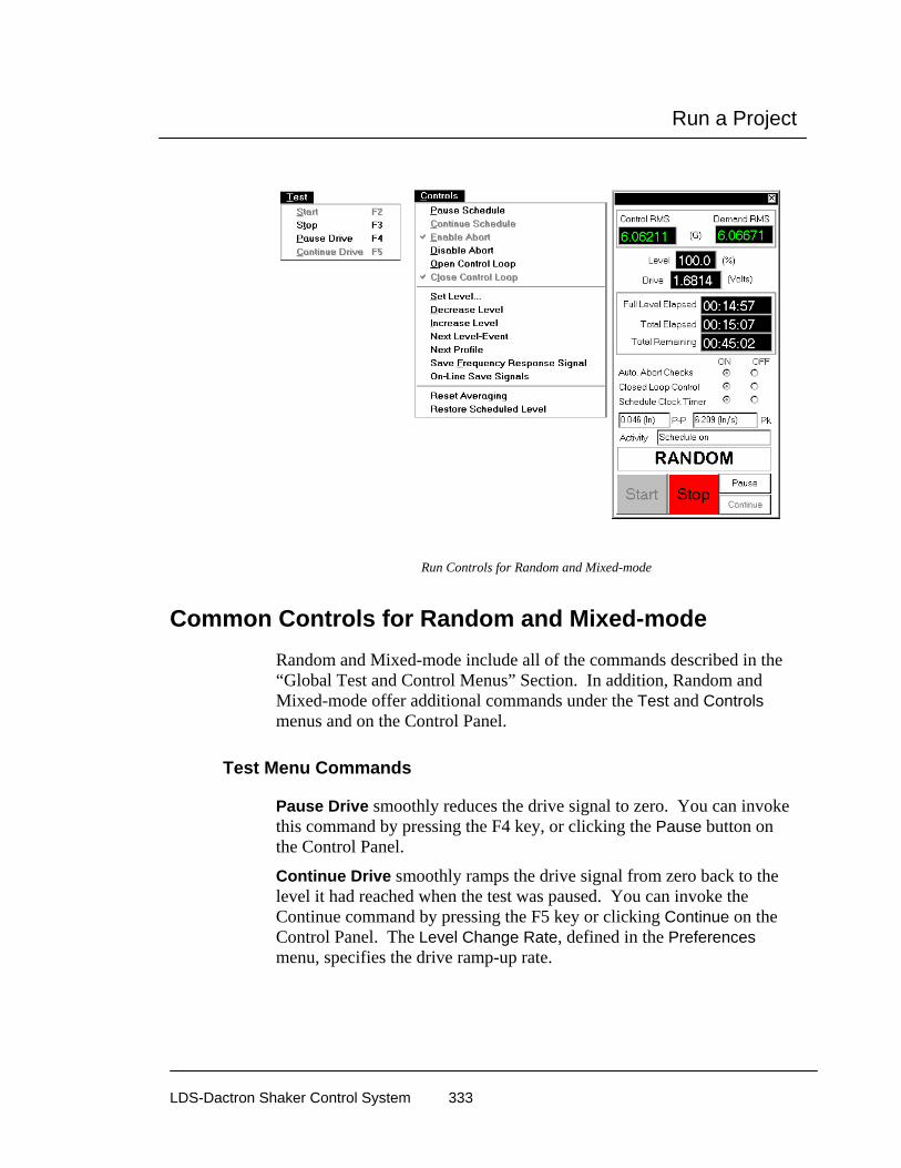
Run a Project
LDS-Dactron Shaker Control System 333
Run Controls for Random and Mixed-mode
Common Controls for Random and Mixed-mode Random and Mixed-mode include all of the commands described in the “Global Test and Control Menus” Section. In addition, Random and Mixed-mode offer additional commands under the Test and Controls menus and on the Control Panel.
Test Menu Commands
Pause Drive smoothly reduces the drive signal to zero. You can invoke this command by pressing the F4 key, or clicking the Pause button on the Control Panel.
Continue Drive smoothly ramps the drive signal from zero back to the level it had reached when the test was paused. You can invoke the Continue command by pressing the F5 key or clicking Continue on the Control Panel. The Level Change Rate, defined in the Preferences menu, specifies the drive ramp-up rate.

Run a Project
LDS-Dactron Shaker Control System 334
Controls Menu Commands
Reset Averaging zeroes the current contents of the averager memory and re-starts the average.
Restore Scheduled Level restores the test to the level specified in the Schedule Level dialog after a manual level change has been made.
Control Panel Commands
In addition to the Start and Stop buttons on the control panel, there are other commands or “switches”. These switches duplicate some of the items on the Test and Controls menus.
Auto Abort Checks (On/Off) indicates the status of the Auto Abort Checks and provides On or Off “radio” buttons. There are no automatic Abort checks when this control is set to Off. For this condition, an operator must continuously monitor the test.
Closed Loop Control (On/Off) indicates the Closed Loop Control status and provides On or Off “radio” buttons. The measured system transfer function is continuously updated when Closed Loop is On. If Closed Loop is off, the drive signal is still updated to produce a gaussian random signal, but there is no correction for changes in the spectrum shape of the control signal.
Schedule Clock Timer (On/Off) duplicates the Pause/Continue Schedule commands in the Controls menu.
Pause smoothly reduces the drive signal to zero output.
Continue smoothly ramps the drive signal from zero back to level it had reached when the test was “paused.”

Run a Project
LDS-Dactron Shaker Control System 335
Run Controls for Mixed-mode Under the Controls menu RoR, SoR, and SRoR offer commands to toggle the narrowbands or tones On and Off.. SoR also has a special control panel for user manual control of the sweep direction and sweep hold/release for a single tone.
Mixed-mode Commands for Turn On/Off Tones and Bands
To use the single tone sweep controls you must make sure only one tone is active. You can do so by either programming the Schedule so that only one tone is on or by using the Turn on/Off SoR Tones selection under the Controls menu.
Mixed-mode Commands for Turn On/Off Tones and Bands

Run a Project
LDS-Dactron Shaker Control System 336
Swept Sine, RSTD, & Sine Oscillator Run Controls
Run Controls for Sine and RSTD Run Controls for Sine and RSTD Projects are found under the Test and Controls menus and on the Control Panel. The Control Panel also includes status information, such as the test Control Peak (level) and Full Level (Time).
Run Controls for Sine and RSTD
Run Controls for Sine Oscillator Run Controls for a Sine Oscillator Project are found under the Test and Controls menus and on the Control Panel. The Control Panel also includes status information, such as the current test Frequency (Hz), test Level (volts), and Sweep Direction.

Run a Project
LDS-Dactron Shaker Control System 337
Run Controls for Sine Oscillator
Common Controls for Sine, RSTD, and Sine Oscillator Sine and RSTD include all of the commands described in the “Global Test and Control Menus” Section. In addition, Sine and RSTD offer additional commands under the Test and Controls menus and on the Control Panel. Sine Oscillator also includes all of the Test Menu commands that Sine and RSTD have. The Controls Menu shares some common commands with Sine and RSTD, but has a different set of additional commands.
Test Menu Commands
Pause Drive smoothly reduces the drive signal to zero. You can also invoke this command by pressing the F4 key, or clicking the Pause button on the Control Panel.
Continue Drive smoothly ramps the drive signal from zero back to the level that it had reached when the test was “paused”. You can also invoke this command by pressing the F5 key, or by selecting it from the

Run a Project
LDS-Dactron Shaker Control System 338
Control Panel. The Level Change Rate, which is defined in the Preferences menu, specifies the drive ramp-up rate.
Hold Sweep halts the sweep and keeps the sine at the current frequency until the Release Sweep commands is given. The F6 key also invokes this command.
Release Sweep resumes the sweep, at the same rate and in the same direction prior to the Hold Sweep command. The F7 key also invokes this command.
Controls Menu Commands for Sine and RSTD
Next Sweep Event forces a jump to next sweep event defined in the Schedule.
Sweep Down causes the sine to sweep in the direction of decreasing frequency. Pressing the F8 key or the Sweep Down icon also execute this command.
Sweep Up causes the sine to sweep up in the direction of increasing frequency. Pressing the F9 key or the Sweep Up icon also execute this command.
Set Frequency allows you to change the frequency to any value within the bounds of the defined test.
Decrease Frequency causes the sine to move down one frequency increment. The frequency increment is defined as a fractional octave value in the Preferences menu. This command is active during a scheduled sweep or if the Schedule Clock Timer is set to Off. It is not available if the sweep has been halted by a Hold Sweep command.
Increase Frequency causes the sine to move up one frequency increment. The frequency increment is defined as a fractional octave value in the Preferences menu. This command is active during a scheduled sweep or if the Schedule Clock Timer is set to Off. It is not available if the sweep has been halted by a Hold Sweep command.
Restore Scheduled Level restores the test to the level specified in the Schedule Level dialog after a manual level change has been made.
Controls Menu Commands for Sine Oscillator
The Controls Menu Commands for Sine Oscillator shares the following common commands with Sine and RSTD: Set Level, Sweep Down, Sweep Up, Set Frequency, and On-Line Save Results. The additional commands Sine Oscillator has are described below.

Run a Project
LDS-Dactron Shaker Control System 339
Adjust Sensitivity invokes the Adjust Sensitivity dialog shown below for on-line updating of input channel sensitivity (mv/(EU)). Based on the Expected Input Level entered, you can update the channel sensitivities for all enabled input channels by clicking on the Get New Sensitivity button.
On-line updating of input channel sensitivity using the Adjust Sensitivity Dialog Box
Note: The following Sine Oscillator commands are separate menu items, but were combined for clarity.
Decrease Level by (1 V, 100 mV, 10 mV, 1 mV) decreases the Drive signal by the specified Level increment.
Increase Level by (1 V, 100 mV, 10 mV, 1 mV) increases the Drive signal by the specified Level increment.
Decrease Frequency by (100 Hz, 10 Hz, 1 Hz, 0.1 Hz) causes the sine to shift down by the specified Frequency increment.
Increase Frequency by (100 Hz, 10 Hz, 1 Hz, 0.1 Hz) causes the sine to shift up by the specified Frequency increment.

Run a Project
LDS-Dactron Shaker Control System 340
Control Panel Commands for Sine and RSTD
In addition to the Start and Stop buttons on the Control Panel, there are other commands or “switches”. These switches duplicate some of the items on the Test and Controls menus.
Auto. Abort Checks (On/Off) indicates the status of the Auto Abort Checks and provides On or Off “radio” buttons. If automatic Abort checks are off, and an operator must continuously monitor the test.
Closed Loop Control (On/Off) indicates the Closed Loop Control status and provides On or Off “radio” buttons. The measured system transfer function is continuously updated when Closed Loop is On. When it is off, the drive signal is not updated so the sine amplitude will stay constant as the sweep proceeds.
Schedule Clock Timer (On/Off) duplicates the Pause/Continue Schedule commands in the Controls menu.
Pause smoothly reduces the drive signal to zero output.
Continue smoothly ramps the drive signal from zero back to the level had reached when the test was “paused.”
Control Panel Commands for Sine Oscillator
In addition to the Start and Stop buttons on the Control Panel, there are other commands for Sine Oscillator. These commands duplicate some of the items on the Test and Controls menus.
Drive Mode allows you to select between two types of drive modes: Fixed Frequency or Frequency Scanning. Fixed Frequency provides for fixed/dwell frequency tests based on the current test frequency setting. Frequency Scanning provides for sine sweep tests based on the specified Sweep Type and Sweep Direction parameters.
Control Panel Drive Mode drop-down setting
Level (volts) provides incremental Drive signal setting.
Start Sweeping causes the sine sweep to start.
Stop Sweeping causes the sine sweep to stop.

Run a Project
LDS-Dactron Shaker Control System 341
Low Frequency is the lowest frequency of the sine sweep in Hertz.
High Frequency is the highest frequency of the sine sweep in Hertz.
Start Frequency is the starting frequency of the sine sweep in Hertz.
Sweep Type allows you to set the sweep type for your test. For a Logarithmic sweep, the sweep rate is defined in Octaves/minute. For a Linear sweep, the sweep rate is defined in Hz/second.
Sweep Direction causes the sine to sweep up/down in the direction of increasing/decreasing frequency.
Resonance Search Window
The Resonance Search Window is a window that displays the plot of a transmissibility signal as defined by the “Transmissibility signals dialog”. Also displayed on this window is a table describing each resonance found by the system. A resonance is defined by the Resonance Search Criteria.
Selecting Resonance Search Window from the Window Menu
Each resonance found by the system will have a marker placed on it and its information displayed in the table. Resonance information displayed in the table includes resonant Frequency, Amplitude Ratio, and Q-factor. Note: that you must press Crtl-Q in order display or update resonance information in the table.
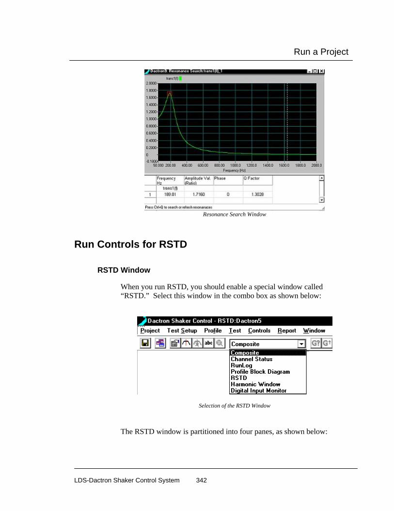
Run a Project
LDS-Dactron Shaker Control System 342
Resonance Search Window
Run Controls for RSTD
RSTD Window
When you run RSTD, you should enable a special window called “RSTD.” Select this window in the combo box as shown below:
Selection of the RSTD Window
The RSTD window is partitioned into four panes, as shown below:

Run a Project
LDS-Dactron Shaker Control System 343
Typical RSTD Window
The left-upper corner Pane is called "RSTD Log". It will display a time stamped history of the search sweep.
The left-lower corner Pane is referred to as the "Resonance List". It displays the list of all resonant frequencies scheduled for dwell testing. The frequency, transmissibility amplitude ratio, phase angle, and Q value for each resonant frequency are displayed. Frequencies that have been “removed”, by user editing, are labeled Excluded under the Dwell column. Include means that this frequency is to be included in the dwell test.
Editing the RSTD Resonance List
The list of resonant frequencies, together with their characteristics such as Q values and transmissibility amplitude ratios, may be edited prior to starting the dwell test. The user can remove resonances from the dwell list or insert additional dwell frequencies.
With phase-tracked dwell, special care should be taken when manually inserting frequencies in the dwell list. Any added frequency should be close to a resonance appearing in the transmissibility function. Otherwise, the system may not be able to lock on to the resonance and do the dwell.
Click the Add button to add frequencies to the list.

Run a Project
LDS-Dactron Shaker Control System 344
Click the Remove button to delete frequencies from the dwell list.
There are a number of ways to remove specific frequencies:
• By resonance sequence number: The resonance sequence number is the number listed under the "Res #" column
• By quality factor (Q value): You can remove all resonant frequencies with Q values less than a specified threshold value.
• By transmissibility ratio: You can remove all the resonant frequencies with transmissibility amplitude ratios less than a specified threshold.

Run a Project
LDS-Dactron Shaker Control System 345
Classical Shock, SRS Synthesis, and TTH Run Controls
Run Controls for Classical Shock, SRS Synthesis, and TTH Projects are found under the Test and Controls menus and on the Control Panel. The Control Panel also includes status information, such as the test Control Peak (level) and Full Level Elapsed (Pulses).
Run Controls for Shock, SRS Synthesis and TTH
Common Controls for Shock, SRS Synthesis, and TTH Shock, SRS Synthesis, and TTH include all of the commands described in “Global Test and Control Menus” Section. They also have additional commands under the Controls menu and on the Control Panel.
Test Menu Commands
Pause Drive smoothly reduces the drive signal to zero. You can invoke this command by pressing the F4 key, or clicking the Pause button on the Control Panel.

Run a Project
LDS-Dactron Shaker Control System 346
Continue Drive smoothly ramps the drive signal from zero back to the level it had reached when the test was paused. You can invoke the Continue command by pressing the F5 key or clicking Continue on the Control Panel. The Level Change Rate, defined in the Preferences menu, specifies the drive ramp-up rate.
Controls Menu Commands
Single Pulse is active when the Schedule is Off (or paused). This command causes output of one pulse at the level shown on the Control Panel level readout. You can use the G, G-up, or G-down icon commands to set the level (the level readout is immediately updated) prior to a Single Pulse command. The F10 key or Single Pulse icon may also be used for this command.
Toggle Sign inverses the polarity (positive or negative) for the next pulse output.
Restore Scheduled Level restores the test to the level specified in the Schedule Level dialog after a manual level change has been made.
Control Panel Commands
In addition to the Start and Stop buttons on the control panel, there are other commands or “switches”. These switches duplicate some of the items on the Test and Controls menus.
Auto. Abort Checks (On/Off) indicates the status of the Auto Abort Checks and provides On or Off “radio” buttons. If automatic Abort checks are off, an operator must continuously monitor the test.
Closed Loop Control (On/Off) indicates the Closed Loop Control status and provides On or Off “radio” buttons. The measured system transfer function is continuously updated when Closed Loop is On. It is generally a good idea to use “On” when performing low-level equalization or if the shaker system is very non-linear (such as for hydraulic shakers). Once at full level, Closed Loop can be turned off to minimize the processing time after each output. This also allows a faster rate of pulse output (the delay between pulses is minimized).
Schedule Clock Timer (On/Off) duplicates the Pause/Continue Schedule commands in the Controls menu.
Inverse Pulse inverses the polarity (positive or negative) for the next pulse output.

Run a Project
LDS-Dactron Shaker Control System 347
Pre-Test Drive Pause for TTH During pre-test, the drive output may be paused after each frame to allow a quality assessment of the system transfer function (Hsys) estimate. If Hsys is satisfactory, the rest of the pre-test may be skipped and the scheduled test immediately started. To use this approach, first check the Pause after each output checkbox in the Control Parameters dialog box. Then, after any pre-test output pause, simply click the Pre-test to Normal Test button on the Control Panel.
The figure below shows the a TTH Control Panel display with Pre-test to Normal Test button active.
Pre-test to Normal Test Button for the TTH Control Panel
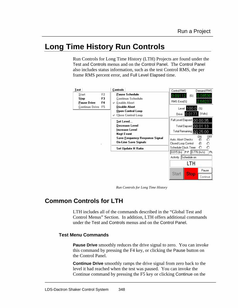
Run a Project
LDS-Dactron Shaker Control System 348
Long Time History Run Controls Run Controls for Long Time History (LTH) Projects are found under the Test and Controls menus and on the Control Panel. The Control Panel also includes status information, such as the test Control RMS, the per frame RMS percent error, and Full Level Elapsed time.
Run Controls for Long Time History
Common Controls for LTH LTH includes all of the commands described in the “Global Test and Control Menus” Section. In addition, LTH offers additional commands under the Test and Controls menus and on the Control Panel.
Test Menu Commands
Pause Drive smoothly reduces the drive signal to zero. You can invoke this command by pressing the F4 key, or clicking the Pause button on the Control Panel.
Continue Drive smoothly ramps the drive signal from zero back to the level it had reached when the test was paused. You can invoke the Continue command by pressing the F5 key or clicking Continue on the

Run a Project
LDS-Dactron Shaker Control System 349
Control Panel. The Level Change Rate, defined in the Preferences menu, specifies the drive ramp-up rate.
Controls Menu Commands
Set Update H Ratio sets the feedback gain for the system transfer function calculation. This value ranges from zero to 0.5. A value of zero inhibits any updating of the transfer function after the pre-test. Any value greater than zero causes the transfer function to be updated during the test based on the latest control loop. If the H Update Ratio is set to 0.5, then a new transfer function is calculated by equally weighting the old transfer function and the transfer function from the latest control loop. Typical H Update Ratio values are from 0.1 to 0.35. If the shaker system or test article is highly non-linear, then it may be necessary to use a value near to 0.5 to enhance control accuracy. Caution should be used, however, as a very high value for H Update Ratio can degrade the control accuracy under some conditions.
Control Panel Commands
In addition to the Start and Stop buttons on the control panel, there are other commands or “switches”. These switches duplicate some of the items on the Test and Controls menus.
Auto Abort Checks (On/Off) indicates the status of the Auto Abort Checks and provides On or Off “radio” buttons. There are no automatic Abort checks when this control is set to Off. For this condition, an operator must continuously monitor the test.
Closed Loop Control (On/Off) indicates the Closed Loop Control status and provides On or Off “radio” buttons. The measured system transfer function is continuously updated when Closed Loop is On. If Closed Loop is off, the drive signal is still updated to produce a gaussian random signal, but there is no correction for changes in the spectrum shape of the control signal.
Schedule Clock Timer (On/Off) duplicates the Pause/Continue Schedule commands in the Controls menu.
Pause smoothly reduces the drive signal to zero output.
Continue smoothly ramps the drive signal from zero back to level it had reached when the test was “paused.”

Run a Project
LDS-Dactron Shaker Control System 350
Special On-Line Displays for LTH LTH features a special Profile Output Index display pane. This display shows the entire profile waveform with a sweeping, reverse-color cursor band that highlights the segment of the profile currently being output. Easier test monitoring and anticipation of test events are made possible by this special display.
LTH On-Line Display of the Profile Output Index
Summary of F Key Commands Many of the frequently used measurement commands and setup menus are directly accessible via special function keys.

Run a Project
LDS-Dactron Shaker Control System 351
Random and Mixed-mode
F2 F3 F4 F5 F6 F7 F8 F9F1 F10
Help Start Stop Pause Continue
Swept Sine and RSTD
F2 F3 F4 F5 F6 F7 F8 F9F1 F10
Help Start Stop Pause Continue Hold Release Sweep SweepSweep Sweep Down Up
Classical Shock, SRS Synthesis, and TTH
F2 F3 F4 F5 F6 F7 F8 F9F1 F10
Help Start Stop SinglePulse
Long Time History
F2 F3 F4 F5 F6 F7 F8 F9F1 F10
Help Start Stop Pause Continue

Run a Project
LDS-Dactron Shaker Control System 352
Special On-Line Displays A number of special displays are available to maket test monitoring easier. These displays are accessed via the combo pull-down menu and the Windows menu.
Combo Pull-Down Menu
This section provides only an overview of the special on-line displays. See the “Windows Menu” in Section 6, “Creating Screens and Reports”, for more detailed information on the setups and features for these special displays.
Channel Status Window The Channel Status window provides a convenient “bar meter” display of the input signal levels. This display is invaluable for troubleshooting startup problems and for monitoring the test during both the Pre-Test and Test phases.

Run a Project
LDS-Dactron Shaker Control System 353
Channel Status Window
Multiple Plots
This view can be selected by right clicking on the Channel Status display and selecting Multiple Plots from the pop up menu. This view shows all enabled input channel signals in an oscilloscope type view.
The format can be modified by right clicking on the Channel Status view and selecting Display Setup from the pop-up menu.
Run Log Window The Run Log Window documents the sequence of system and operator actions during the test. The current test event is highlighted the line.

Run a Project
LDS-Dactron Shaker Control System 354
Parameter Summary Window The Summary Window selection displays a table listing the setup parameters of the test.
Summary Window

Run a Project
LDS-Dactron Shaker Control System 355
Numeric Display The Numeric Display provides a large-size digital readout visible from across a room. You may choose to display either a Signal property or an item of system Status. The choice between Signal and Status readout is made in the pop-up menu that appears when you right-click in the Numeric Display. The pop-up also provides the opportunity to establish the Display Setup for the active (checked) display type.
Numeric Display of Signal data reflects amplitude by color
The following figure shows the Numerical Indicator Settings dialog that appears when you select Display Setup from the pop-up while Signal is the active display choice.
Chamber Watch Window The Chamber Watch Window shows the status of the Thermal Chamber during a scheduled test. In addition to the current temperature value and setpoint value, the Chamber Watch window also lists the Low/High input limits, warning levels, and alarm levels.

Run a Project
LDS-Dactron Shaker Control System 356
Chamber Watch Window
Project Sequence Control and Monitoring
Project Sequence Start To initiate an automatic execution of a sequence of project files, as defined in the Project Sequence Setup dialog box, select Start Project Sequence under the Project menu. This selection only appears in the top-level menu. If you have a project file open, you must first close this project in order to access Start Project Sequence.

Run a Project
LDS-Dactron Shaker Control System 357
Project Sequence Monitoring To monitor the status of a project sequence you can invoke the Project Sequence Watch window. This window identifies the project currently running, all of the projects that will be run as part of the mission profile, and the current cycle number being executed for the project sequence. To activate this special display, go to the Windows menu and select Project Sequence Watch.
Project Sequence Watch Window

Run a Project
LDS-Dactron Shaker Control System 358
Project Sequence Log After a project sequence has finished you can use the the Project Sequence Log to view a log of each event in the sequence. This log is accessed under the Project menu on the Start-up Page.

Create Screens and Reports
LDS-Dactron Shaker Control System 359
6 Create Screens and Reports Following the selection and/or creation of a Project, you create displays of the data that you wish to see and setup automatic Report generation. These two activities use the Report, Window, Pane, and Cursor menus.
Displays and reports are very much inter-related. In order to provide a complete report of the testing activity, you must have displays that can document the work. It is important to understand the relationship of Windows and Panes in the context of the LDS-Dactron Shaker Control System. In this section, the creation of displays will be explained in the context of the Window menu. The display contents will be explained in the Pane menu and finally the Report menu will explain the documentation process.
Test Screen Display with Multiple Data Display Windows
Create Screens and Reports
LDS-Dactron Shaker Control System 360
What is a Pane A Pane is a portion of a Window. Windows in the LDS-Dactron Shaker Control System function just like windows in any MS Windows application. They can be opened, sized, moved, positioned, closed, minimized, maximized and iconized. A window for LDS-Dactron’s applications can have one, two or four “panes”. Each Pane can display test data in a variety of formats to assist in monitoring the test, analyzing data, and documenting results.
Standard Windows Each Project includes three or four default windows. A Composite, Channel Status, and a Run Log window are present in all projects. A third default window, the Profile Block Diagram, is available only for Random, Mixed-mode, and Sine projects. These default windows are “standard” windows and are always available for display.
Note: At least one window has to be open. If you close all windows, you will close the project
Composite Window The Composite window is the primary window for viewing during a test run. It is always available and initially appears in a standard format. However it is user-customizable directly through it’s own controls. The Channel Status and Profile windows rely on Project definition for their respective content. The controls of the Composite window are similar to those of the optional “Customized” windows. These controls will be explained in the next section: Pane menu.

Create Screens and Reports
LDS-Dactron Shaker Control System 361
Composite Window for Random
For Random, Sine, SoR and RoR the Composite window can contain the control, the reference, the high abort, the low abort, the high alarm, and the low alarm traces on one plot. For Shock and SRS Synthesis, the Composite window can contain the control, the reference, the high abort, or the low abort data traces.
Profile Block Diagram Window Another type of standard One-Pane window is the Profile Block Diagram. This window is a graphic representation of the project/schedule run order. This window also allows immediate access to the Profile and Schedule dialogs for any project in the Block Diagram. (You can also access these dialogs through the Profile menu.) For more information on this window, see “Profile Block Diagram” in Section 4.

Create Screens and Reports
LDS-Dactron Shaker Control System 362
The Customized Window The final type of window available is the Customized window. Customized windows use a multiple Pane concept. You can select from a number of Pane formats in the Window menu.
Window Menu The Window menu is used to create and arrange the various window types. The Pane menu contains selections to create new windows or to choose the active window. This section explains the creation of data display windows.
One-Pane Window Selecting One-Pane on the Window menu creates a Customized data display with a single plot area. Each Customized window is assigned a name derived from the Signal name chosen as the first trace to the plot. If the same Signal name is used in another window as the first trace, then this window’s name will be the Signal name with an appended number: 1,2,3 and so on. For example, if input2(f) is selected twice as the first trace of new windows, the two window names would input2(f)_0 and input2(f)_1.

Create Screens and Reports
LDS-Dactron Shaker Control System 363
2D Displays
Two-Pane Horizontal Window
The Two-Pane Horizontal selection creates a Customized two-pane window with a horizontal divider bar. The Two-Pane window contains two separate and independent user- definable plots. The horizontal divider bar allows sizing the two plots, relative to each another, within the window.
Two-Pane Horizontal Window
Two-Pane Vertical Window
The Two-Pane Vertical selection creates a Customized two-pane window with a vertical divider bar.

Create Screens and Reports
LDS-Dactron Shaker Control System 364
Two-Pane Vertical Window
Four-Pane Window
The Four-Pane selection creates a Customized four-pane window with both horizontal and vertical divider bars.
Four-Pane Window
Composite
Selecting Composite will recreate the composite window if it has been closed.

Create Screens and Reports
LDS-Dactron Shaker Control System 365
3D Displays
Waterfall Window
The Waterfall Window selection creates a Customized one-pane window display in which a signal can be processed and displayed as a Waterfall plot.
Waterfall Window
Waterfall displays are an advanced option and a full description on the setup and use of these displays is in Section 10, “Special Displays and Functions”
Cascade and Tile These standard MS Windows controls arrange the open windows in either Cascade (windows layered on top of each other) or Tile (rows and columns of equal size windows) arrangements.
Tool Bar, Status Bar, and Control Panel If you need to additional space on the display screen, you can display or hide the Tool Bar, the Status Bar and the Control Panel.
Tool Bar contains single-click access to many window operations and test control and report functions. Section 7, “Tool Bar and Mouse Controls”, describes the Tool Bar functions.
Status Bar contains information about various functions that the system is performing.

Create Screens and Reports
LDS-Dactron Shaker Control System 366
Control Panel is an essential item to have on the screen. It provides quick access to controls and status readouts. During test runs, it is not a good idea to suppress this portion of the display just to gain space.
Active Window Selection The bottom of the Window menu lists the open windows. A check mark next is next to the name of the Active Window.
Parameter Summary Window The Summary Window selection displays a table listing the setup parameters of the test.
Summary Window

Create Screens and Reports
LDS-Dactron Shaker Control System 367
Numeric Display The Numeric Display provides a large-size digital readout visible from across a room. You may choose to display either a Signal property or an item of system Status. The choice between Signal and Status readout is made in the pop-up menu that appears when you right-click in the Numeric Display. The pop-up also provides the opportunity to establish the Display Setup for the active (checked) display type.
Numeric Display of Signal data reflects amplitude by color
The following figure shows the Numerical Indicator Settings dialog that appears when you select Display Setup from the pop-up while Signal is the active display choice.
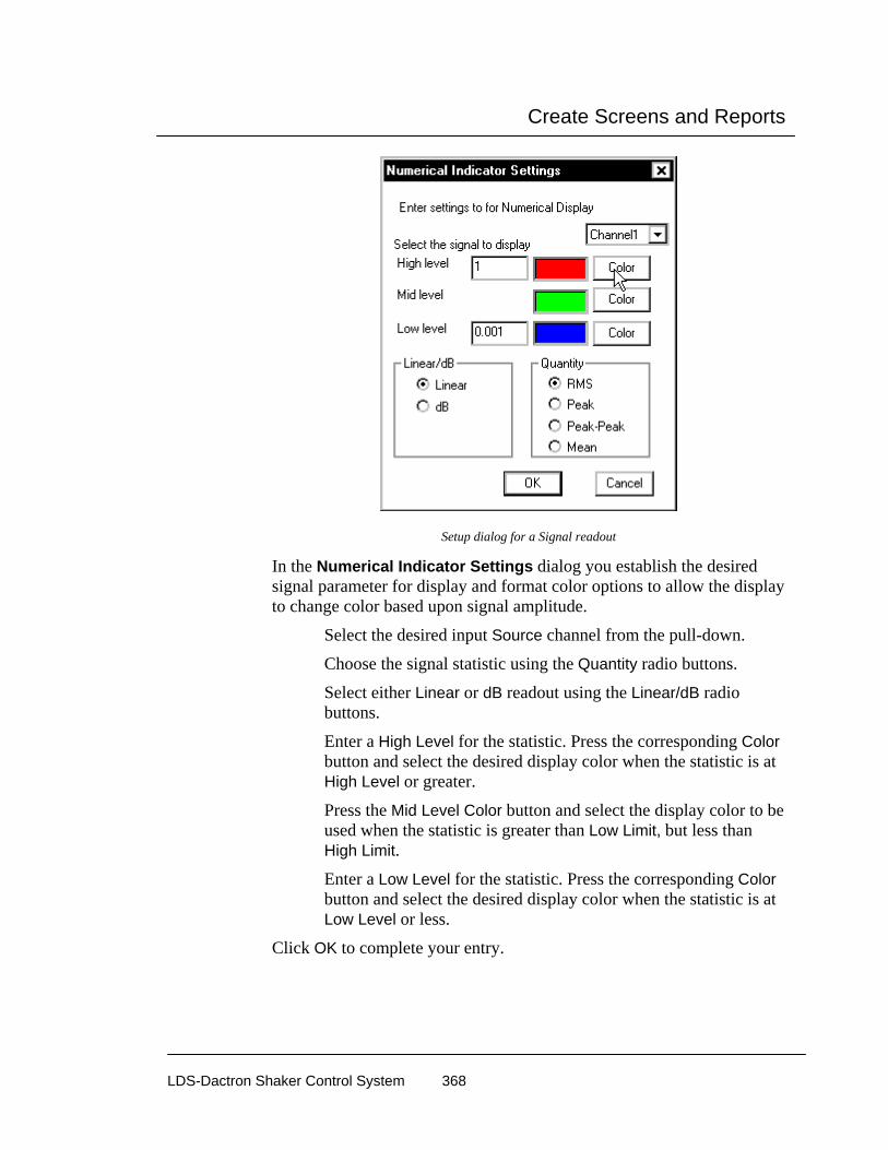
Create Screens and Reports
LDS-Dactron Shaker Control System 368
Setup dialog for a Signal readout
In the Numerical Indicator Settings dialog you establish the desired signal parameter for display and format color options to allow the display to change color based upon signal amplitude.
Select the desired input Source channel from the pull-down.
Choose the signal statistic using the Quantity radio buttons.
Select either Linear or dB readout using the Linear/dB radio buttons.
Enter a High Level for the statistic. Press the corresponding Color button and select the desired display color when the statistic is at High Level or greater.
Press the Mid Level Color button and select the display color to be used when the statistic is greater than Low Limit, but less than High Limit.
Enter a Low Level for the statistic. Press the corresponding Color button and select the desired display color when the statistic is at Low Level or less.
Click OK to complete your entry.

Create Screens and Reports
LDS-Dactron Shaker Control System 369
Numeric Display of a system Statistic
Right click in the Numeric Display and select Status to display a system parameter such as Frequency. Select Display Setup to open the Display Setup dialog shown below.
Display Setup dialog used to format Status readout
Status displays are always made using green characters. You can select the Background Color to make multiple Status readouts instantly distinguishable (and differentiate them from Signal readouts).
Choose the desired system Status number from the Content pull down.

Create Screens and Reports
LDS-Dactron Shaker Control System 370
Specify the desired number of Digits to be displayed.
Select the desired Font.
Select the desired Background Color.
Choose the applicable Units for readout.
Press OK to complete your entry.
Channel Status Window The Channel Status window provides a convenient “bar meter” display of the input signal levels. This display is invaluable for troubleshooting startup problems and for monitoring the test during both the Pre-Test and Test phases.
Channel Status Window
Clipped, Max, Min, Peak and RMS are the input values measured on a frame-by-frame basis. Clipped flags input voltage range overloads. “Clipped #” provides a counter for the number of overloads registered by each channel. The numeric readouts – Max, Min, Peak, and RMS – are calculated as follows:
Max is the largest positive value.
Min is the largest negative value.

Create Screens and Reports
LDS-Dactron Shaker Control System 371
Peak is the larger of Max and the absolute value of Min for Random and Shock applications. For Sine applications Peak represents the averaged zero to peak value for the time data frame. This value is the same as that used for the spectrum display at the current sweep frequency.
RMS is the root mean square value.
Random applications also include a readout of the PSD RMS. This value is based on the averaged PSD for the input channel.
Multiple Plots
This view can be selected by right clicking on the Channel Status display and selecting Multiple Plots from the pop up menu. This view shows all enabled input channel signals in an oscilloscope type view.
The format can be modified by right clicking on the Channel Status view and selecting Display Setup from the pop-up menu.

Create Screens and Reports
LDS-Dactron Shaker Control System 372
Display Setup
Number of rows of plots defines the layout of the graphs. Select 1 to show all graphs in one row. Select 2 to show all graphs in 2 rows.
Channels to be displayed defines which of the enabled input channels will be displayed. The channels can be specified by entering “ALL”, separated by commas (1,2,4), or with a range (1-6).
Display labels for each plot adds the input channel units labels to each plot.
Fit all channels in visible area scales the size of the plots to fill the Channel Status window.
Warning Condition is used to change the color of the waveform to indicate the size of the signal.
Select Quantity defines the measurement to compare to the value. The choices are Peak, RMS and Peak-Peak.
Condition defines the comparison of the signal to the value. The choices are Greater than, Less than, and Equal in between.
Value specifies the value to compare with the signal. When Condition is set to Equal in between, then there are 2 value fields that specify the upper and lower values.

Create Screens and Reports
LDS-Dactron Shaker Control System 373
Run Log Window The Run Log Window documents the sequence of system and operator actions during the test. The current test event is highlighted the line.
Run Log
Chamber Watch Window The Chamber Watch Window shows the status of the Thermal Chamber during a scheduled test. In addition to the current temperature value and setpoint value, the Chamber Watch window also lists the Low/High input limits, warning levels, and alarm levels.
Chamber Watch Window
Project Sequence Window To monitor the status of a project sequence you can invoke the Project Sequence Watch window. This window identifies the project currently running, all of the projects that will be run as part of the mission profile, and the current cycle number being executed for the project sequence.
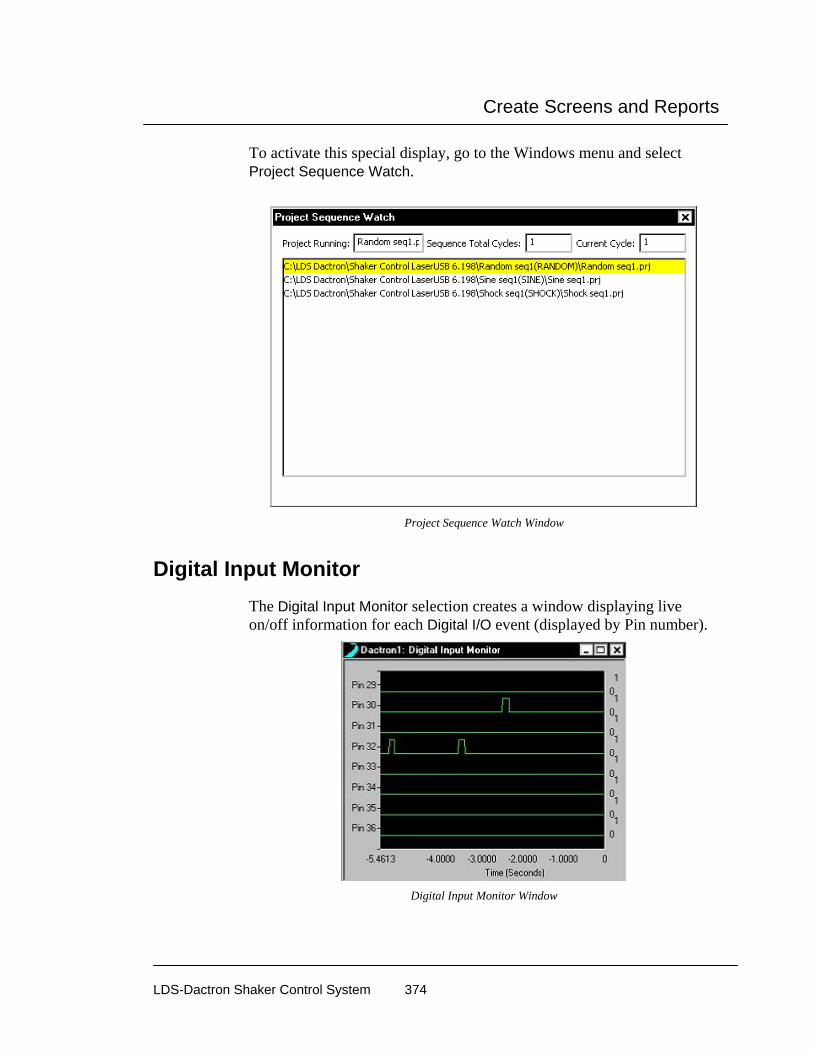
Create Screens and Reports
LDS-Dactron Shaker Control System 374
To activate this special display, go to the Windows menu and select Project Sequence Watch.
Project Sequence Watch Window
Digital Input Monitor The Digital Input Monitor selection creates a window displaying live on/off information for each Digital I/O event (displayed by Pin number).
Digital Input Monitor Window

Create Screens and Reports
LDS-Dactron Shaker Control System 375
Pane Menu The Pane menu is the primary menu for transforming windows and making them display the data that you wish to see in the format that you wish to see it.
Making a Pane the Active Pane Clicking on one of the panes within a window will make that pane active. All selections on the Pane menu will then apply to that pane. (For more information on mouse controls, see Section 7, “Tool Bar and Mouse Controls.”)
Moving the Pane Borders You can change the relative sizes of individual panes within a window by moving the divider bars. To do so position the mouse pointer over a Pane divider bar. A Resize icon will appear. A uni-directional Resize icon allows the divider bar to be dragged horizontally or vertically. To do a combined vertical and horizontal movement, position the mouse pointer over the intersection of the horizontal and vertical dividers bars and then drag the bi-directional Resize icon.
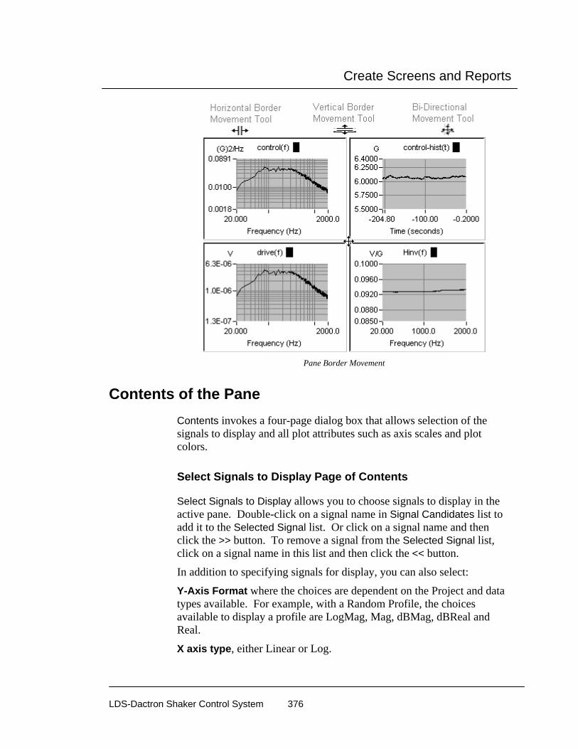
Create Screens and Reports
LDS-Dactron Shaker Control System 376
Pane Border Movement
Contents of the Pane Contents invokes a four-page dialog box that allows selection of the signals to display and all plot attributes such as axis scales and plot colors.
Select Signals to Display Page of Contents
Select Signals to Display allows you to choose signals to display in the active pane. Double-click on a signal name in Signal Candidates list to add it to the Selected Signal list. Or click on a signal name and then click the >> button. To remove a signal from the Selected Signal list, click on a signal name in this list and then click the << button.
In addition to specifying signals for display, you can also select:
Y-Axis Format where the choices are dependent on the Project and data types available. For example, with a Random Profile, the choices available to display a profile are LogMag, Mag, dBMag, dBReal and Real.
X axis type, either Linear or Log.
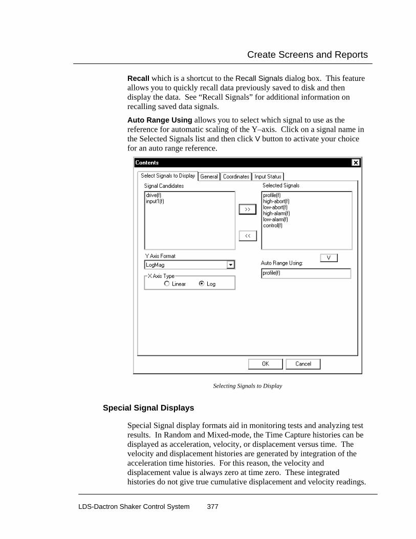
Create Screens and Reports
LDS-Dactron Shaker Control System 377
Recall which is a shortcut to the Recall Signals dialog box. This feature allows you to quickly recall data previously saved to disk and then display the data. See “Recall Signals” for additional information on recalling saved data signals.
Auto Range Using allows you to select which signal to use as the reference for automatic scaling of the Y–axis. Click on a signal name in the Selected Signals list and then click V button to activate your choice for an auto range reference.
Selecting Signals to Display
Special Signal Displays
Special Signal display formats aid in monitoring tests and analyzing test results. In Random and Mixed-mode, the Time Capture histories can be displayed as acceleration, velocity, or displacement versus time. The velocity and displacement histories are generated by integration of the acceleration time histories. For this reason, the velocity and displacement value is always zero at time zero. These integrated histories do not give true cumulative displacement and velocity readings.
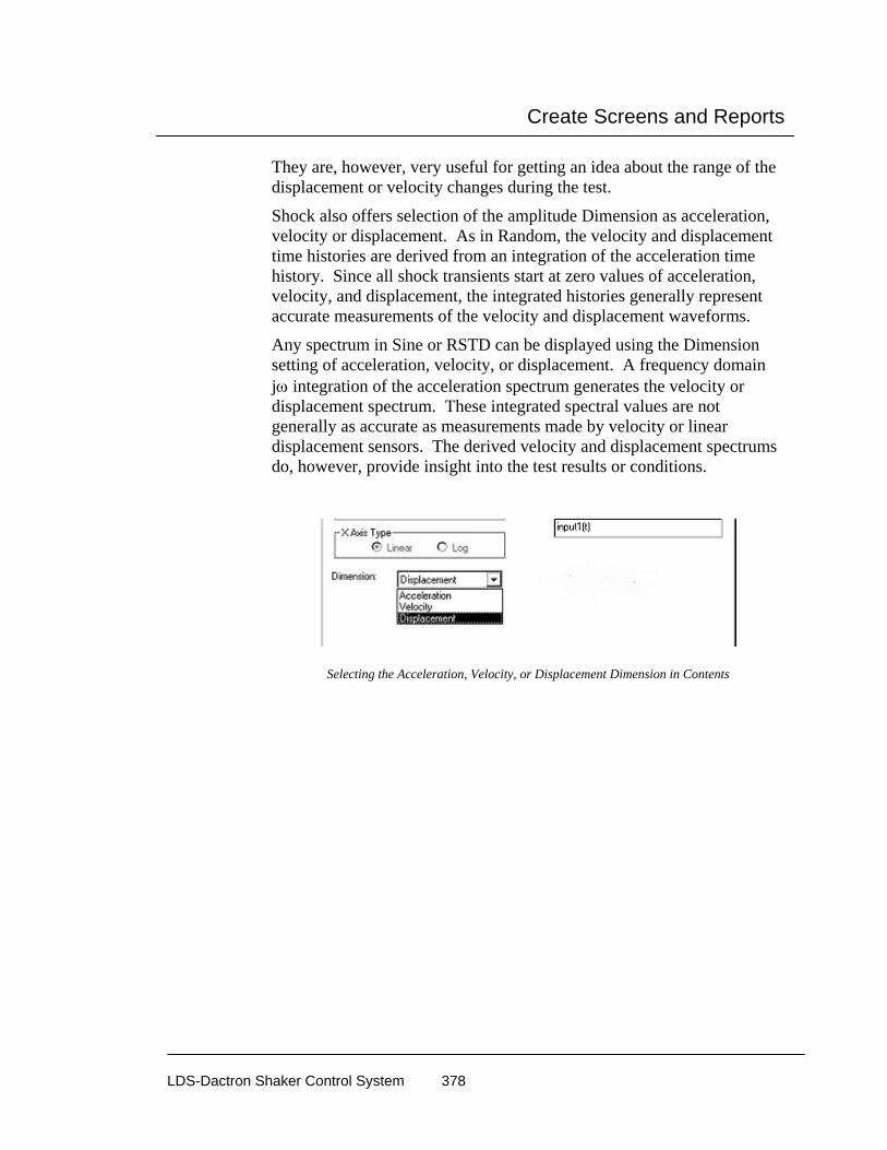
Create Screens and Reports
LDS-Dactron Shaker Control System 378
They are, however, very useful for getting an idea about the range of the displacement or velocity changes during the test.
Shock also offers selection of the amplitude Dimension as acceleration, velocity or displacement. As in Random, the velocity and displacement time histories are derived from an integration of the acceleration time history. Since all shock transients start at zero values of acceleration, velocity, and displacement, the integrated histories generally represent accurate measurements of the velocity and displacement waveforms.
Any spectrum in Sine or RSTD can be displayed using the Dimension setting of acceleration, velocity, or displacement. A frequency domain jω integration of the acceleration spectrum generates the velocity or displacement spectrum. These integrated spectral values are not generally as accurate as measurements made by velocity or linear displacement sensors. The derived velocity and displacement spectrums do, however, provide insight into the test results or conditions.
Selecting the Acceleration, Velocity, or Displacement Dimension in Contents

Create Screens and Reports
LDS-Dactron Shaker Control System 379
Example Time Histories with Acceleration, Velocity, and Displacement Dimension
SoR and SRoR offer control tone as a special signal display. These choices allow the control tones signals to be plotted as they are in Sine. The tone acceleration (peak) is plotted versus frequency just as in a swept-sine test.
Control Tone Signals for Display in SoR and SRoR

Create Screens and Reports
LDS-Dactron Shaker Control System 380
Example of Control Tone Acceleration versus Frequency Plot (upper pane)
In Shock, any SRS may be displayed as an A/V/D vibration monograph. This plot format has grid lines for acceleration, velocity, and displacement. This plot format is selected via the Y-Axis menu of Contents as show below.
Selecting the Acceleration/Velocity/Displacement Vibration Monograph Display Format

Create Screens and Reports
LDS-Dactron Shaker Control System 381
Example SRS in AVD Vibration Monograph Format
General Page of Contents
The General page provides tools to set the colors for the plot areas. To change an item’s properties, highlight the item in the Category list. Make the changes desired and then select OK. To determine which attributes can be changed, see the individual descriptions of each category below.
Grid is the background grid lines drawn on the Pane when signals are plotted. The color and the style of the grids may be changed.
Tic Mark is the short line drawn between the major grids on the plot axes. The color of the tic marks may be changed.
Title is the name assigned to this pane. The title appears on the title bar of the window. The title text may be changed.
yTitle shows the vertical units for the measurement. The title text may be changed.

Create Screens and Reports
LDS-Dactron Shaker Control System 382
xTitle shows the horizontal units for the measurement. If the signal is in the time domain, the X Title default is Time (seconds). If the signal is in the frequency domain, the X Title default is Frequency (Hz). The title text may be changed.
Text refers to any text displayed in the Pane such as the Y Title or the X Title. The text color and the font may be changed. To change the text font, click the Font button and choose from the selections in the dialog box.
Background Color refers to the background of the plot area. The background color may be changed. The default background color is black.
Frame Color refers to the region outside the plot area. The frame color may be changed. The default frame color is gray.
General Page to Set Plot Colors, Textures and Text Font
Coordinates Page of Contents
Coordinates allows selection of the vertical and horizontal scaling of the Plot. It also allows you to choose the numerical format for axes scale values.

Create Screens and Reports
LDS-Dactron Shaker Control System 383
Setting Plot Scales and Scale Label Formats
The X- and Y-Axis Range offer three types of scaling methods: Full, Auto and Fixed.
In the Full scaling method, the display boundaries are calculated based on the maximum and minimum values of the signal in the axis. The boundaries are calculated for each Pane. If more than one signal is selected for display, the signal used will be the one shown in the Auto Range Using field in the Select Signals to Display page of this dialog box.
Auto is similar to Full but leaves more headroom for display.
Fixed allows entry of the values for the display boundaries. If invalid numbers are entered, the system will automatically change the numbers into meaningful values. For example, if the number of Y Top Boundary
Create Screens and Reports
LDS-Dactron Shaker Control System 384
is less than that of Y Bottom Boundary, the system will change the values.
Note: After the ZOOM-In command is executed, both X and Y-axes are set to Fixed. After the ZOOM-Out command is executed, the system will restore the scale settings.
Label Mode controls the way numbers are displayed. For example, the value 0.035 can be displayed as:
0.035 floating point description
3.5e-3 scientific description
35m short note description
The Floating point format straightforward and easy to understand. However, for extremely small or big values, it requires many digits to represent data values. In this case, use the scientific or short-note description.
Scientific uses a mantissa (the numbers before the “e”) and an exponent (the numbers after “e”) for the data display. The number “3.5e-3” means 3.5 ×10⁻³.
Short-Note uses the following industry conventions to describe a value:
G stands for Giga and is 10 to the ninth power.
M stands for Mega and is 10 to the sixth power.
k stands for kilo and is 10 to the third power.
m stands for milli and is 10 to the minus third power.
u stands for micro and is 10 to the minus sixth power.
p stands for pico and is 10 to the minus ninth power.
n stands for nano and is 10 to the minus twelfth power.
Input Status Page of Contents
When a Pane contains either input(t) or input(f) signals, you can add input status readouts such as the RMS or peak value.

Create Screens and Reports
LDS-Dactron Shaker Control System 385
The Max, Min, Peak and RMS values are instantaneous estimates base on a single data frame. The PSD RMS, which is only available in Random, is the RMS value estimated from the averaged power-spectrum of that channel. The PSD RMS has less variance than the RMS.
Input Status Readouts
Input Status Readouts on a Pane
The numeric readouts – Max, Min, Peak, and RMS – are calculated from time history for the current data frame. These values are calculated as follows:
Max is the largest positive value.

Create Screens and Reports
LDS-Dactron Shaker Control System 386
Min is the largest negative value.
Peak is the larger of Max and the absolute value of Min for Random and Shock applications. For Sine applications Peak represents the averaged zero to peak value for the time data frame. This value is the same as that used for the spectrum display at the current sweep frequency.
RMS is the root mean square value.
Random applications also include a readout of the PSD RMS. This value is based on the averaged PSD for the input channel.
Pane Default Parameters The Pane Default Parameter dialog is used to customize the settings so that every new pane inherits the default settings. Select Pane Default Parameters from the Pane menu.
General Parameters sets the color, line style and font of the pane. Click on items in the list then click on the Color, Font, or Line Style controls to change the default settings.
Signal Related Parameters set the scaling of the pane. Select either Time Domain Signal, Frequency Domain Signal, or Ratio Signal, then Change the Y axis Format or the X axis type.

Create Screens and Reports
LDS-Dactron Shaker Control System 387
When the settings are made, click on the OK button. Every new pane that is generated will open with the new default settings.
Add and Delete Cursor Mark The Add Mark and Delete Mark commands insert or remove cursors marks, that is tabulated X and Y value readouts, from the active pane. To add a Mark annotation box in the pane move the cursor to the desired position on the data trace and either select Add Mark from the Pane menu or hold down the “Ctrl” and “M” keys together. When multiple signals are overlaid the up arrow key allows selection of the data trace to mark. You can move the mark annotation box by using the mouse to click and drag. To remove a Mark annotation box from a pane, simply click on the Delete Mark menu item.
Note: Cursors are a primary analysis tool, and there are many ways to invoke, control and use them. Section 7, “Tool Bar and Mouse Controls”, provides extensive detail on the use of cursors.
Add and Delete Annotation Annotations can be added to any Pane. The Add Annotation command invokes a mouse crosshair pointer to select the annotation block position size. Simply place the crosshair pointer in the desired position on the plot, then hold down the left mouse button and drag until you get the right size block. Delete Current Annotation removes the annotation block from the plot. The Annotation tool is covered in detail in Section 7, “Tool Bar and Mouse Controls.”
Zoom In and Zoom Out You Zoom In, or magnify a portion of a plot, by placing the mouse pointer anywhere on the plot, and then you click-and-drag the zoom box over the part of the plot you want to magnify. Zoom Out allows you to restore the X-Y scaling of the signal plot to the previous level of magnification. The Pane stores all Zoom-In information so that it can be restored to each previous magnification level.

Create Screens and Reports
LDS-Dactron Shaker Control System 388
Auto. Fit Y-Axis Auto. Fit Y-Axis automatically scales the Y-axis for the active Pane. Auto Fit is on if a checkmark appears by this menu item. If there is no checkmark, Auto Fit is off.
Pane Pop-Up Menu The Pane Pop-Up menu can be accessed from any pane by right clicking on the pane. It contains many features that are most commonly used and gives quick access to commonly used dialogs.
Contents opens the Contents dialog.
Line Properties provides settings for the line color and thickness for each individual signal.
Copy opens a sub menu that lists all signals in the pane that can be copied individually, as well as the option to copy the Pane Bitmap or copy All Signals. Copy allows the user to copy a signal to the Windows Clipboard. This is a fast and convenient method to export data into other Windows software such as Excel and Word.
The available options under Copy are described below.

Create Screens and Reports
LDS-Dactron Shaker Control System 389
Pane Bitmap copies a bitmap image of the current pane into the Windows Clipboard. This image can then be pasted into any Windows application such as Word or an email program.
All Signals copies all signals to the clipboard.
Copy opens a sub menu that lists all signals in the pane in addition to the Pane Bitmap and All Signals options. Select the signal to copy by pointing and releasing the mouse button. Then switch to another Windows application to paste the data. The data will be pasted in rows and columns with column headings to indicate the units and scaling as shown below.
Export to Excel copies the values of the selected, or all signals to an Excel spreadsheet. If Excel is not launched then the application is automatically launched. A new spreadsheet is opened and the values are copied into a formatted table. The data is also dynamically linked to the Shaker Control application so that as the measurement continues, or is started again, the values in the Excel spreadsheet are continuously updated. This feature allows advanced calculations that are not available in the Shaker Control software to be performed within the Excel software.
Save is a simple method to manually save signals without going to the Signal Manager dialog. Right click on the pane that contains the signal and select Save then Save All Signals or select the signal to save by pointing and releasing the mouse button. The signal will then be saved to disk according to the settings in the Save Signal Manager.

Create Screens and Reports
LDS-Dactron Shaker Control System 390
Cache is a simple method to manually cache signals without going to the Cache Signal Manager window. Right click on the pane that contains the signals and select Cache then All Signals or select the signal to cache by pointing and releasing the mouse button. The signal will then be cached and automatically added to the pane.
Cursor Menu Cursor functions provide a flexible analysis tool. Single and dual cursors give precise value readouts and relative delta X and Y readouts. Peak and valley cursors automatically detect and mark the maximum or minimum values for a data trace(s). Harmonic cursors also supply information on the relationships of signal components with a fundamental cyclic signal.
Cursor features are accessed and activated by pointing the mouse at an active cursor, and then right-clicking. Note this menu is not available when the cursor is not pointed near the cursor.
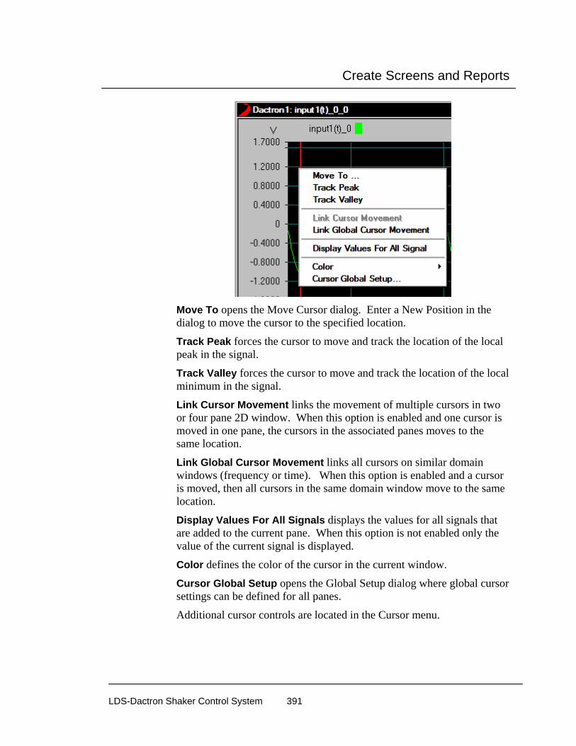
Create Screens and Reports
LDS-Dactron Shaker Control System 391
Move To opens the Move Cursor dialog. Enter a New Position in the dialog to move the cursor to the specified location.
Track Peak forces the cursor to move and track the location of the local peak in the signal.
Track Valley forces the cursor to move and track the location of the local minimum in the signal.
Link Cursor Movement links the movement of multiple cursors in two or four pane 2D window. When this option is enabled and one cursor is moved in one pane, the cursors in the associated panes moves to the same location.
Link Global Cursor Movement links all cursors on similar domain windows (frequency or time). When this option is enabled and a cursor is moved, then all cursors in the same domain window move to the same location.
Display Values For All Signals displays the values for all signals that are added to the current pane. When this option is not enabled only the value of the current signal is displayed.
Color defines the color of the cursor in the current window.
Cursor Global Setup opens the Global Setup dialog where global cursor settings can be defined for all panes.
Additional cursor controls are located in the Cursor menu.

Create Screens and Reports
LDS-Dactron Shaker Control System 392
Note: Cursors are a primary analysis tool, and there are many ways to invoke, control and use them. Section 7, “Tool Bar and Mouse Controls”, provides extensive detail on the use of cursors.
Add and Delete Normal Cursor The Add Normal Cursor and Delete Normal/Peak/Valley Cursor commands insert or remove basic cursors from the active pane. Each pane can have two cursors. Activating both cursors provides delta x and y readouts between the two cursors. To make coarse cursor movements, position the mouse over the cursor (the mouse pointer will change to the shape of a hand) and then drag the cursor to the new X-axis position. The left and right arrows on the keyboard provide for fine cursor movement. The up and down keyboard arrows toggle the active trace used for the value readout box.

Create Screens and Reports
LDS-Dactron Shaker Control System 393
Add and Delete Normal Y Cursor The Add Normal Y Cursor and Delete Normal Y Cursor commands insert or remove one y cursor from the active pane. Each pane can have two y cursors. Activating both cursors provides delta y readouts between the two cursors. To make coarse cursor movements, position the mouse over the cursor (the mouse pointer changes to the shape of a hand) and then drag the cursor to the new y-axis position. The up and down arrows on the keyboard provide for fine cursor movement.
Sideband Cursors Sideband cursors show a series of vertical lines a specified distance from the main cursor in a frequency plot. You set the number or sideband cursors and the frequency spacing using the Sideband Cursor Setup dialog in the Cursor Global Setup dialog. Then add a cursor to the pane and select Enable Sideband Cursors from the Cursor menu. The text box lists the signal at each sideband cursor. To remove the sideband cursors select Disable Sideband Cursors from the Cursor menu.
Add and Delete Peak Cursors Peak cursors automatically find the peaks of a data trace and mark these peaks. The peak marks use sequentially numbered tags for referencing to the list of X and Y value readouts in the mark annotation box. For displays with multiple overlaid signals, use the up or down arrow key to select the data trace to peak mark. You can move the mark annotation box by using the mouse to click and drag. To remove the peak mark annotation box from a pane, simply click on Delete Normal/Peak/Valley Cursor.
Add and Delete Valley Cursors Valley cursors automatically find the valleys of a data trace and mark these valleys. The Valley cursors operate in the same manner as the Peak cursors as described above.
Add and Delete Harmonic Cursors Harmonic cursors show a series of markers referenced to a specified “fundamental” frequency. The harmonic markers are positioned at integer multiples of the fundamental frequency. Add Harmonic Cursor

Create Screens and Reports
LDS-Dactron Shaker Control System 394
places harmonic cursors in the active pane. You set the fundamental cursor frequency either by using the Global Cursor Setup dialog or by using the mouse to click and drag the fundamental cursor. To get a X-Y value readout for the harmonic cursor, go the Window Selector box on the toolbar and click on Harmonic Window. When multiple signals are overlaid the up arrow key allows selection of the data trace to place harmonic markers on. You can move the mark annotation box by using the mouse to click and drag. To remove the valley mark annotation box from a pane, simply click on Delete Harmonic Cursor.
Calculate Q Factor with Normal Cursor The Q Factor can be automatically calculated from a spectrum plot by selecting Calculate Q Factor with Normal Cursor from the Cursor menu. This option is only available when a normal cursor is added to a pane. Move the normal cursor near a peak in the spectrum plot and the text readout will display the Q Factor and the percent damping, computed from:
Q Factor = fc/(f2-f1)
% damping = 1/(2*Q Factor)
Where fc is the center frequency at the peak, f1 and f2 are the half power points computed from 3 dB below fc.
Find Nearest Peak or Valley Find Nearest Peak moves the active cursor from its current position to the closest peak of the data trace. Likewise, Find Nearest Valley moves the active cursor to the closest data trace valley.
Cursor Global Setup Select this option to open the Cursor Global Setup dialog.

Create Screens and Reports
LDS-Dactron Shaker Control System 395
Normal Cursor
This tab controls the properties of the normal cursor.
Display the complete engineering units in the cursor window adds units to the x and y values displayed in the cursor annotation box.
Display the overall RMS when applicable displays the Overall RMS value for the pane, in addition to the x and y values at the cursor position.
Label Mode controls the way numbers are displayed. The options are described in detail in the section describing the Contents dialog earlier in this chapter.
Peak/Valley Setup
The Peak/Valley Setup dialog allows you to set the number of peaks or valleys to find and mark. For example, setting the Number of Peak/Valley to 3 and then clicking on Add Peak Cursor marks the three highest peaks of the active data trace.

Create Screens and Reports
LDS-Dactron Shaker Control System 396
Harmonic Cursor Setup
The Harmonic Cursor Setup dialog sets the frequency for the reference, or fundamental cursor, and the number of harmonic cursors to use. Setting the Fundamental Cursor Frequency at 100 Hz and the Number of Cursors to 4 would cause, for example, cursors to appear at 100, 200, 300, 400 and 500 Hz.
Fundamental Cursor allows you to enter the frequency for the reference, or fundamental cursor.

Create Screens and Reports
LDS-Dactron Shaker Control System 397
Index Setup allows you to choose either the Default Index, which places the harmonic cursors at integer multiples of the Fundamental Cursor, or a Custom Index, which allows you to enter a Delta Frequency. Using the latter option, the cursors appear evenly spaced from the Fundamental Cursor instead of at integer multiples.
THD Display defines how the total harmonic distortion is displayed when the harmonic cursor is enabled.
Number of Cursors allows you to enter the number of cursors you need.
Sideband Cursor Setup
The Sideband dialog page allows you to select the number of sideband pairs (cursors) and the frequency spacing. This option is only available if there is already one normal cursor in the pane.
Number of Sideband Pairs - The number of pairs of cursors on each side of the central frequency. For example, if you select two sideband pairs, you will have two sideband cursors on each side of the main cursor.
Frequency - The difference in frequency between each of the sideband cursors. For example, if you select to have two sideband cursors at a spacing of 1000Hz and the main cursor is at 5000Hz, you will see sideband cursors at 3000Hz, 4000Hz, 6000Hz, and 7000Hz. The cursors at 4000Hz and 6000Hz constitute the first pair and those at 3000Hz and 7000Hz constitute the second pair.
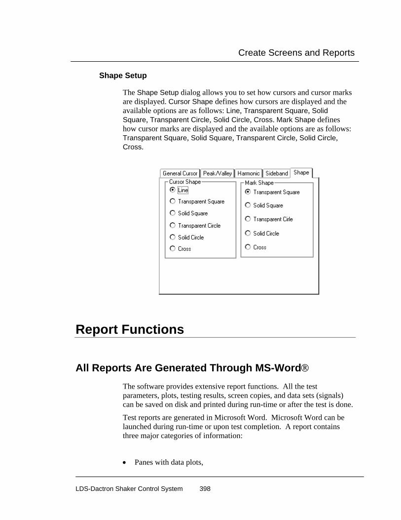
Create Screens and Reports
LDS-Dactron Shaker Control System 398
Shape Setup
The Shape Setup dialog allows you to set how cursors and cursor marks are displayed. Cursor Shape defines how cursors are displayed and the available options are as follows: Line, Transparent Square, Solid Square, Transparent Circle, Solid Circle, Cross. Mark Shape defines how cursor marks are displayed and the available options are as follows: Transparent Square, Solid Square, Transparent Circle, Solid Circle, Cross.
Report Functions
All Reports Are Generated Through MS-Word® The software provides extensive report functions. All the test parameters, plots, testing results, screen copies, and data sets (signals) can be saved on disk and printed during run-time or after the test is done.
Test reports are generated in Microsoft Word. Microsoft Word can be launched during run-time or upon test completion. A report contains three major categories of information:
• Panes with data plots,

Create Screens and Reports
LDS-Dactron Shaker Control System 399
• application screen bitmaps, and
• test parameter listings.
An Example of a Report Generated in MS-WORD
The system generates appropriate temporary data files in the current Run folder and MS-Word imports them whenever necessary.
Temporary data files can be generated:
Manually, using the on-line command, or
Automatically, via the schedule.
Selecting an on-line command such as Current Pane under the Report menu and clicking Create Report causes MS-Word to open immediately and lets it import the temporary data files. A Word document will be created at that time.
However, if the entry Save Results is inserted in a schedule or, the Save Results command is selected during run-time, MS-Word will not be opened at that time. Instead, the temporary data files will be saved into the current Run folder. Later, the temporary files may be moved into

Create Screens and Reports
LDS-Dactron Shaker Control System 400
MS-Word by selecting Output Saved Results to MS-Word. The data flow is as follows:
*.scn files (bitmaps of screen copies)*.txt files (parameters)*.pan files (plots)
RUN folder
On-line commandSave Results
schedule entrySave Results MS-Word Document
CommandOutput Saved
Results to MS-Word
print...ShakerControl
Software
Data Flow in Generating Reports
Difference between a Pane and Screen Bitmap A plot may be printed by making a screen bitmap copy or by creating a plot for the Pane directly. Creating the Pane plot directly is the best strategy unless it is necessary to print out more than one plot per page.
The Pane plot is created by a special technique in MS-Word, which saves the drawing algorithms of each pane. The picture is crystal clear and the plot may be enlarged or reshaped without losing resolution. The Pane plot is always on a white background. The line colors can be changed.
Printouts contain only one plot per page. To print several plots on the same page in a specific layout, the screen bitmap copy must be used.
Run-time Status Attached to the Plot When a plot is created, some run-time statistics are attached to the plot automatically by the system. For example, a Random plot includes:
• Plot Header
• Project Name,
• Profile Name,

Create Screens and Reports
LDS-Dactron Shaker Control System 401
• Test Type,
• Run Folder Name,
• Current Level,
• Control RMS and Demand RMS,
• Elapsed Time and Remaining Time,
• Time Data saved, and
• Time of Report Generation.
For MS-Word 2007 Users
Setting Word 2007 Defaults
The Word macros used by the Quick Report macros have been set for use with the following default and font settings:
• Font: Times New Roman, 10 point
• Paragraph: Single Line spacing with 0 pt spacing Before and After
Set the Word defaults to the above settings for the best results in the Word document layout.
Setting Word 2007 Macro Security Microsoft Word includes security features to protect against macro viruses. This feature is not in versions of Microsoft Word 2002 or prior. For LDS-Dactron Quick Reports to work with Microsoft Word 2007 you must follow the procedure noted below, which describes how to add the LDS-Dactron folder and its sub-folders as a Trusted Location.Microsoft Word includes security features to protect against macro viruses. This feature is not in versions of Microsoft Word 2002 or prior. For LDS-Dactron Quick Reports to work with Microsoft Word 2007 you must follow the procedure noted below, which describes how to add the LDS-Dactron folder and its sub-folders as a Trusted Location.

Create Screens and Reports
LDS-Dactron Shaker Control System 402
Add the LDS-Dactron folder and its sub-folders as a Trusted Location
In order to enable LDS-Dactron Quick Reports in Microsoft Word 2007 a user must add the LDS-Dactron folder and its sub-folders as a Trusted Location. To do so,
1. Open Microsoft Word 2007.
2. Click the Microsoft Office Button .
3. Click on the “Word Options” button at the bottom of the
menu.
4. In the “Word Options” window, click on “Trust Center” then click the “Trust Center Settings” button.
5. In the “Trust Center Settings” window click on “Trusted Locations”, then select the “Add new location” button.

Create Screens and Reports
LDS-Dactron Shaker Control System 403
6. In the “Microsoft Office Trusted Location” window, click on the
“Browse” button to specify the path to be “C:\LDS Dactron\” and enable the checkbox “Subfolders of this location are also trusted”. Click on OK to close the window.
7. Click on OK to close the “Trust Center” window then on OK again to close the “Word Options” window.
The above noted procedure must be done before you generate a Quick Report and the Trusted Locations list must retain the LDS-Dactron folder
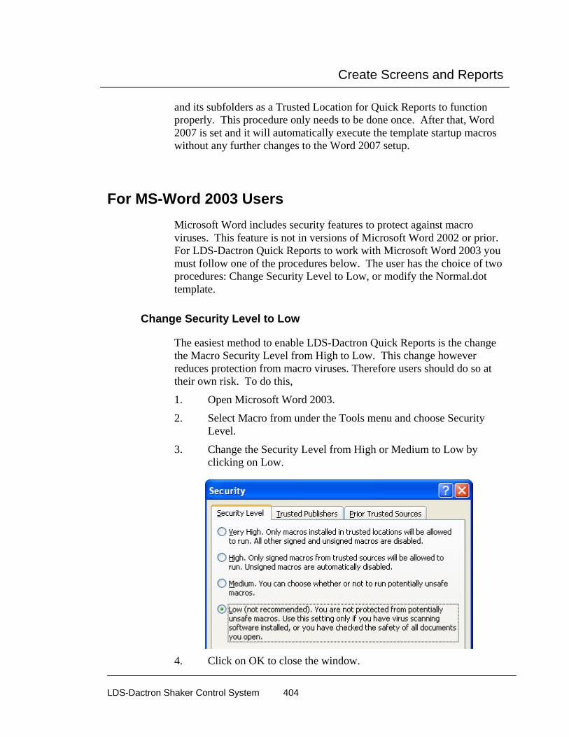
Create Screens and Reports
LDS-Dactron Shaker Control System 404
and its subfolders as a Trusted Location for Quick Reports to function properly. This procedure only needs to be done once. After that, Word 2007 is set and it will automatically execute the template startup macros without any further changes to the Word 2007 setup.
For MS-Word 2003 Users Microsoft Word includes security features to protect against macro viruses. This feature is not in versions of Microsoft Word 2002 or prior. For LDS-Dactron Quick Reports to work with Microsoft Word 2003 you must follow one of the procedures below. The user has the choice of two procedures: Change Security Level to Low, or modify the Normal.dot template.
Change Security Level to Low
The easiest method to enable LDS-Dactron Quick Reports is the change the Macro Security Level from High to Low. This change however reduces protection from macro viruses. Therefore users should do so at their own risk. To do this,
1. Open Microsoft Word 2003.
2. Select Macro from under the Tools menu and choose Security Level.
3. Change the Security Level from High or Medium to Low by clicking on Low.
4. Click on OK to close the window.

Create Screens and Reports
LDS-Dactron Shaker Control System 405
This must be done before you generate a Quick Report and Security Level must remain at Low for LDS-Dactron Quick Reports to function properly. This procedure only needs to be done once. After that, Word 2003 is set and it will automatically execute the template startup macros without any further changes to the Word 2003 setup. If the user prefers not to change the Security Level to Low, then the alternative is to modify the Normal.dot template as described below.
Modify the Normal.dot Template
The first time that Word 2003 is invoked by Quick Report command form with an LDS-Dactron application, the following error message appears:
First go to the “Tools” menu and select “Macro.” The Macros dialog box will be displayed. Click on the “Organizer…” button. In the Organizer dialog,
1. Select the Macro Project Items tab
2. Go to the “Macro Project Items available in” selector on the left and choose “Report.dot(Template).”
3. Go to the “Macro Project Items available in” selector on the right, and choose “Normal.dot (global template).”

Create Screens and Reports
LDS-Dactron Shaker Control System 406
4. Delete the “AutoOpen” macro in the “Normal.dot:” template by
clicking first on the “AutoOpen” macro on the right and then clicking on the “Delete” button.
5. Copy “AutoOpen” macro from the “Report.dot:” template to the “Normal.dot:” template by clicking first on the “AutoOpen” macro on the left and then clicking on the “Copy >>” button.
6. Delete the “AutoOpen” macro in the “Report.dot:” template by clicking first on the “AutoOpen” macro on the left and then clicking on the “Delete” button. The Macro Project Items dialog should look like the figure below.

Create Screens and Reports
LDS-Dactron Shaker Control System 407
7. Finally, click on the “Close” button.
8. Exit Word 2003 and it will prompt you to save “Report” (report.dot). Select "Yes" on this prompt.
This completes the Word 2003 macro conversion procedure. Now Word 2003 will automatically execute the Word macros used by LDS-Dactron’s Quick Report utility.
Use the MS-Word Template The user can take advantage of MS-Word to customize the report by using a Word Template. For example, the company logo may be put into the header. When a report is created using this template, each page of the report will have a logo on the top. To create templates, follow the steps below.

Create Screens and Reports
LDS-Dactron Shaker Control System 408
Step 1: A Word template called dot1 is created. It has a special header as shown below:
Step 2: Save template dot1, into the LDS-Dactron\bin folder:
Step 3: When you create the report, select the dot1 template:
Step 4: The documents generated will use the dot1 template.

Create Screens and Reports
LDS-Dactron Shaker Control System 409
Generate a Color Plot for the Pane For color printing, the Pane plot can be saved with color information. To enable the color function, go to Option under Report. Under the Each time you save pane(s) section, click Use color line drawing. This will store the plot traces as color lines. The plot background is always white.

Create Screens and Reports
LDS-Dactron Shaker Control System 410
Enabling Color Line Drawing in the Pane Plot
Note: The bitmap of the screen copy is always in color. For high quality printing, you may want to select white for the background and dark colors for the lines.
Print Multiple Plots per Page Many printers come with driver software capable of printing multiple plots per page. Once you have generated your report in Word, you can set the print properties by going to the File menu, selecting Print, and then going to the Properties dialog. The dialog below shows a typical Properties set up page.
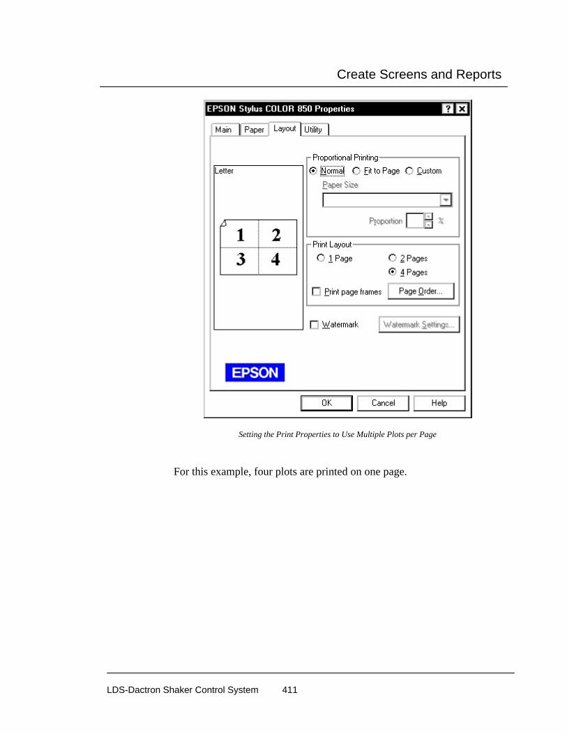
Create Screens and Reports
LDS-Dactron Shaker Control System 411
Setting the Print Properties to Use Multiple Plots per Page
For this example, four plots are printed on one page.
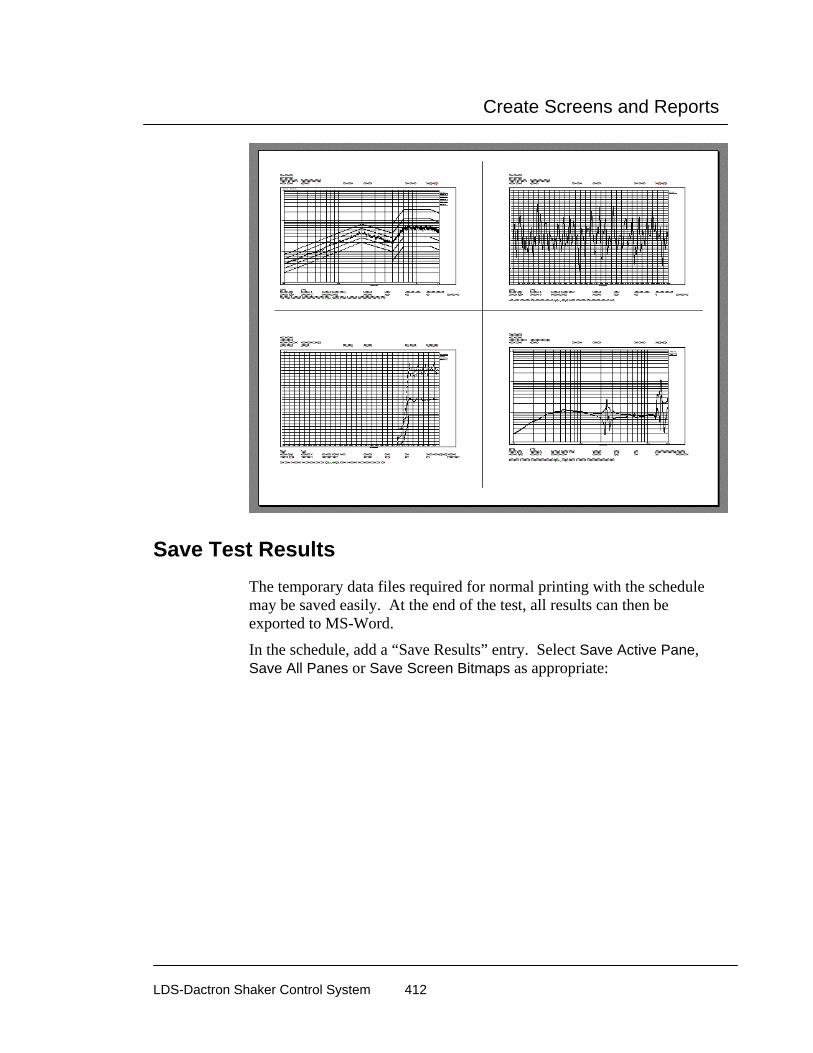
Create Screens and Reports
LDS-Dactron Shaker Control System 412
Save Test Results The temporary data files required for normal printing with the schedule may be saved easily. At the end of the test, all results can then be exported to MS-Word.
In the schedule, add a “Save Results” entry. Select Save Active Pane, Save All Panes or Save Screen Bitmaps as appropriate:

Create Screens and Reports
LDS-Dactron Shaker Control System 413
Selecting Results to Save
The schedule will execute the command at the appropriate time. The following schedule shows a test with 100 loop times. It will save all panes opened and the application screen bitmap to the Run folder every hour.
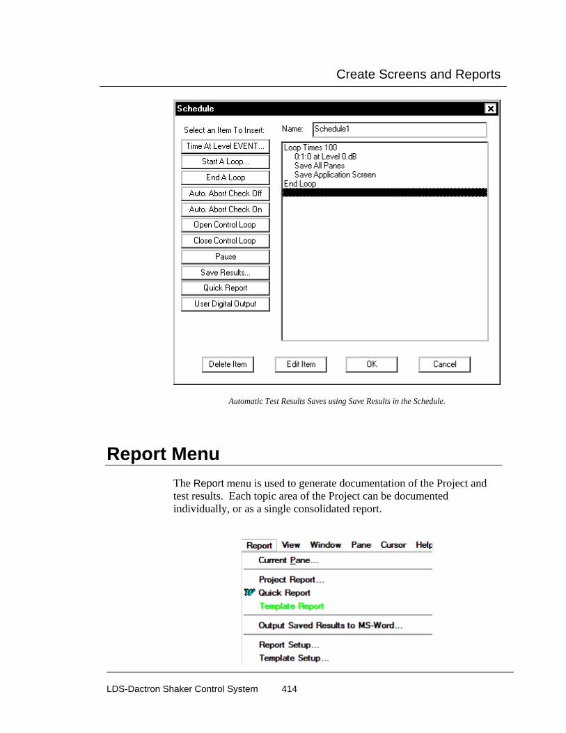
Create Screens and Reports
LDS-Dactron Shaker Control System 414
Automatic Test Results Saves using Save Results in the Schedule.
Report Menu The Report menu is used to generate documentation of the Project and test results. Each topic area of the Project can be documented individually, or as a single consolidated report.

Create Screens and Reports
LDS-Dactron Shaker Control System 415
Current Pane Current Pane generates an MS-Word document with the active Pane embedded. A hard copy of the plot is easily made using Word’s Print command.
Template is the MS-Word template to use. The default template is Normal. Within Word you can create your template with your company’s logo, or other pertinent information, included in the template header.
Notes provides convenient entry of annotation, such as observations on the data, special test conditions, etc., to embed in the Word document along with the plot. This text appears on the page following the Pane plot.
Test ID to Customize and Add Test Information

Create Screens and Reports
LDS-Dactron Shaker Control System 416
The Test ID dialog is used to customize the Quick Report Content. The headers and report content can be modified for each report. This feature gives the user the ability to add standard text to Quick Reports such as: DUT, Serial Number, Operator name, etc… The Test ID dialog can also prompt the user before each test to enter this information.
Customize Field Label opens the Customize Label dialog. This dialog can be used to modify the labels in the Test ID dialog for any specific application.
Insert Label adds a new Field Label below the highlighted label.
Add Label adds a new Field Label to the end of the list.
Delete Label removes the highlighted label.
The Usage column in the Test ID dialog defines where the field information will be placed in the Quick Report.

Create Screens and Reports
LDS-Dactron Shaker Control System 417
Header 1 places the information at the top of every page in Header 1. Note only one row can be assigned to Header 1 in the Test ID dialog.
Header 2 places the information below Header 1 on every page. Note only one row can be assigned to Header 2 in the Test ID dialog.
End of Report places the information at the end of the report, after all content define in the Quick Report Setup dialog. There is no limit to the number of rows that can be assigned to the end of the report in the Test ID dialog.
None suspends this information from the current report. This Append mode can be used to temporarily withhold information from the Quick Report without deleting the Field Label definition from the Test ID dialog.
The Append Mode field can be used to add a time or sequence number after the content of each entry in the Test ID dialog.
Time Stamp adds the date and time after every entry in the Quick Report
Increment Adds an incrementing number after every entry in the Quick Report. The number increases after every report is generated.
For example if the following fields are defined in the Test ID dialog,

Create Screens and Reports
LDS-Dactron Shaker Control System 418
then the top of the report will include the text:
X512-1
Test 1 of 5 Dec 17,2001 11-06-02.
Project Report Selection of Project Report allows the generation of a listing of individual Project settings, or a consolidated listing of the entire Project setup. All of the setup items checked under Content will be embedded in a new Word document using the template specified in the MS-Word Template selector box.

Create Screens and Reports
LDS-Dactron Shaker Control System 419
Report Setup The Report Setup dialog box allows you to preset the contents of your report. Selecting Quick Report, or clicking on the Quick Report icon, automatically opens MS-Word and generates a report with the contents as specified under Quick Report contents.
Report Setup Dialog Box for Customized Report Composition
Quick Report Setup
Prompt Test ID dialog box at time of the report generation can be used to customize the report content with every new report.
The Legends section provides the following choices for plot customization:
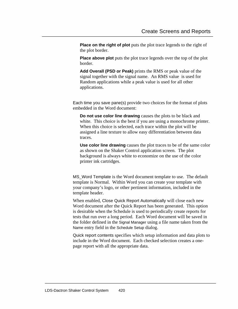
Create Screens and Reports
LDS-Dactron Shaker Control System 420
Place on the right of plot puts the plot trace legends to the right of the plot border.
Place above plot puts the plot trace legends over the top of the plot border.
Add Overall (PSD or Peak) prints the RMS or peak value of the signal together with the signal name. An RMS value is used for Random applications while a peak value is used for all other applications.
Each time you save pane(s) provide two choices for the format of plots embedded in the Word document:
Do not use color line drawing causes the plots to be black and white. This choice is the best if you are using a monochrome printer. When this choice is selected, each trace within the plot will be assigned a line texture to allow easy differentiation between data traces.
Use color line drawing causes the plot traces to be of the same color as shown on the Shaker Control application screen. The plot background is always white to economize on the use of the color printer ink cartridges.
MS_Word Template is the Word document template to use. The default template is Normal. Within Word you can create your template with your company’s logo, or other pertinent information, included in the template header.
When enabled, Close Quick Report Automatically will close each new Word document after the Quick Report has been generated. This option is desirable when the Schedule is used to periodically create reports for tests that run over a long period. Each Word document will be saved in the folder defined in the Signal Manager using a file name taken from the Name entry field in the Schedule Setup dialog.
Quick report contents specifies which setup information and data plots to include in the Word document. Each checked selection creates a one-page report with all the appropriate data.
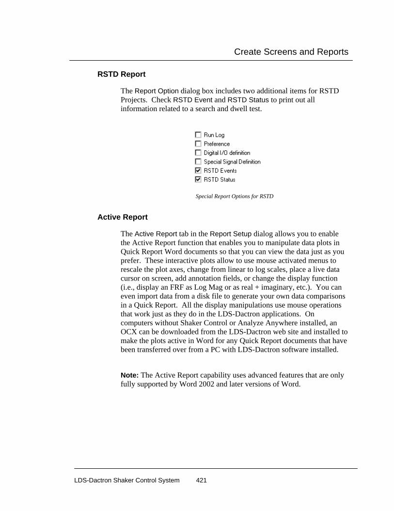
Create Screens and Reports
LDS-Dactron Shaker Control System 421
RSTD Report
The Report Option dialog box includes two additional items for RSTD Projects. Check RSTD Event and RSTD Status to print out all information related to a search and dwell test.
Special Report Options for RSTD
Active Report
The Active Report tab in the Report Setup dialog allows you to enable the Active Report function that enables you to manipulate data plots in Quick Report Word documents so that you can view the data just as you prefer. These interactive plots allow to use mouse activated menus to rescale the plot axes, change from linear to log scales, place a live data cursor on screen, add annotation fields, or change the display function (i.e., display an FRF as Log Mag or as real + imaginary, etc.). You can even import data from a disk file to generate your own data comparisons in a Quick Report. All the display manipulations use mouse operations that work just as they do in the LDS-Dactron applications. On computers without Shaker Control or Analyze Anywhere installed, an OCX can be downloaded from the LDS-Dactron web site and installed to make the plots active in Word for any Quick Report documents that have been transferred over from a PC with LDS-Dactron software installed.
Note: The Active Report capability uses advanced features that are only fully supported by Word 2002 and later versions of Word.

Create Screens and Reports
LDS-Dactron Shaker Control System 422
Report Setup Dialog Box for enabling Active Report
To create an Active Report, follow these simple steps:
a. Enable the Active Report function, by simply clicking on Word Active Report in the Report Type tab of the Report Setup dialog.
b. Generate a Quick Report by using the Report menu and selecting Quick Report or by clicking on the Quick Report icon in the Tool Bar. Note also that you can create an Active Report using Current Pane as well under the Report menu.
An Active Report is automatically generated in Word as follows:
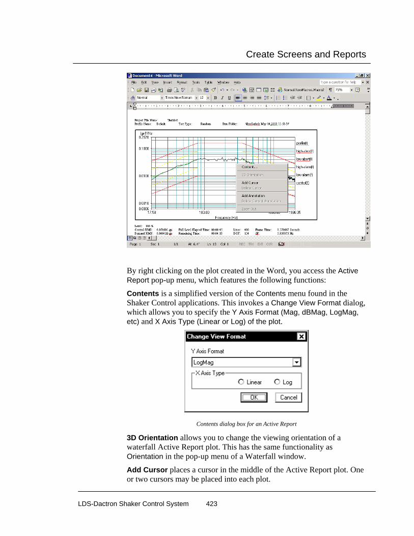
Create Screens and Reports
LDS-Dactron Shaker Control System 423
By right clicking on the plot created in the Word, you access the Active Report pop-up menu, which features the following functions:
Contents is a simplified version of the Contents menu found in the Shaker Control applications. This invokes a Change View Format dialog, which allows you to specify the Y Axis Format (Mag, dBMag, LogMag, etc) and X Axis Type (Linear or Log) of the plot.
Contents dialog box for an Active Report
3D Orientation allows you to change the viewing orientation of a waterfall Active Report plot. This has the same functionality as Orientation in the pop-up menu of a Waterfall window.
Add Cursor places a cursor in the middle of the Active Report plot. One or two cursors may be placed into each plot.
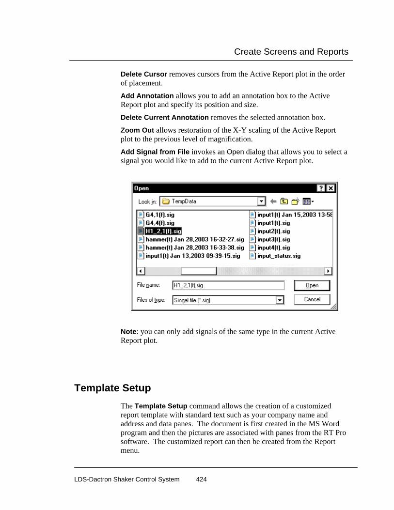
Create Screens and Reports
LDS-Dactron Shaker Control System 424
Delete Cursor removes cursors from the Active Report plot in the order of placement.
Add Annotation allows you to add an annotation box to the Active Report plot and specify its position and size.
Delete Current Annotation removes the selected annotation box.
Zoom Out allows restoration of the X-Y scaling of the Active Report plot to the previous level of magnification.
Add Signal from File invokes an Open dialog that allows you to select a signal you would like to add to the current Active Report plot.
Note: you can only add signals of the same type in the current Active Report plot.
Template Setup The Template Setup command allows the creation of a customized report template with standard text such as your company name and address and data panes. The document is first created in the MS Word program and then the pictures are associated with panes from the RT Pro software. The customized report can then be created from the Report menu.

Create Screens and Reports
LDS-Dactron Shaker Control System 425
Note: The Active Report capability uses advanced features that are only fully supported by Word 2002 and later versions of Word.
A template file must first be created in the MS Word program. To do this, run the MS Word program and select LDS-Dactron from the View menu. This menu is added to MS Word when the RT Pro software is installed. This adds the menu shown below. Create a new document and edit it by adding your company information, standard text and formatting using standard MS Word commands. To add a LDS-Dactron figure, click Insert Picture from the LDS-Dactron menu.
The Inset Picture dialog will prompt for a picture name. Enter a name and click OK. This adds a place holder for data panes that will be imported from the RT Pro software.
Delete picture removes the selected picture from the template file.
Continue to edit the template and add pictures until the template is complete. Then save the file as either a .doc or .tmp file. The image below shows a template document with 2 pictures added.

Create Screens and Reports
LDS-Dactron Shaker Control System 426
After a template file is created and saved, the Template Setup dialog can be used to assign pane data to the template pictures. Select Template Setup from the Report menu. Use the Browse button to locate the template file. The dialog will display a list of the defined pictures in the template file. Select a Picture Name and use the pull-down menu on the right to assign a pane to the picture. The panes must be defined in RT Pro before they appear on the dialog. After all Picture Names have assigned Window Pane Names, click OK.

Create Screens and Reports
LDS-Dactron Shaker Control System 427
Template Report The Template Report command uses the Template Setup settings and creates a new report. The image below shows a report created from the above template file. The live data is copied from RT Pro into the report.

Create Screens and Reports
LDS-Dactron Shaker Control System 428
Output Saved Results to MS-Word The Output Saved Results to MS-Word command allows selection of the saved results to export into MS-Word.

Create Screens and Reports
LDS-Dactron Shaker Control System 429
Output All Saved Results to MS-Word
Run Folder lists the selected directory from which saved results are to be extracted. The default setting for the directory is the currenr Project Run Folder. Use the Browse button to change to a different run folder.
Template is the MS-Word template to use. The default template is Normal. Within Word you can create your template with your company’s logo, or other pertinent information, included in the template header.
Candidates allows you to specify which saved results to export into Word. Double-click on a results name in the Candidates list to add it to the Selected Items list. Or click on a results name and then click the >> button. To remove a result from the Selected Item list, click on a result name in this list and then click the << button. You can also use the Select All Panes/Screens and Remove All Panes/Screens to simplify selection or de-selection of results.
The figure that follows shows an example of the MS-Word document generated automatically using this approach:

Create Screens and Reports
LDS-Dactron Shaker Control System 430
A Report Generated with Various Saved Results (Panes and Screen Bitmaps)
Parameter Summary Window The Parameter Summary Window gives all setup and test settings in one display that can be resized, moved, tiled and closed like any pane. It can be viewed by selecting Parameter Summary from the Window menu or Setup Summary from the pull down menu on the Project Toolbar. Note the Parameter Summary Window contents only refreshes when the window is closed and reopened or when the user clicks on the Parameter Summary Refresh button on the tool bar . If a change is made to a setting and the window is not refreshed then the contents could be inaccurate.

Create Screens and Reports
LDS-Dactron Shaker Control System 431
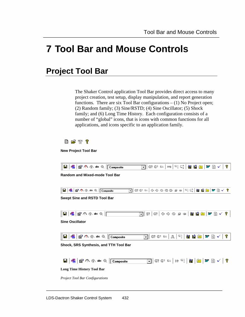
Tool Bar and Mouse Controls
LDS-Dactron Shaker Control System 432
7 Tool Bar and Mouse Controls
Project Tool Bar
The Shaker Control application Tool Bar provides direct access to many project creation, test setup, display manipulation, and report generation functions. There are six Tool Bar configurations – (1) No Project open; (2) Random family; (3) Sine/RSTD; (4) Sine Oscillator; (5) Shock family; and (6) Long Time History. Each configuration consists of a number of “global” icons, that is icons with common functions for all applications, and icons specific to an application family.
New Project Tool Bar
Random and Mixed-mode Tool Bar
Swept Sine and RSTD Tool Bar
Sine Oscillator
Shock, SRS Synthesis, and TTH Tool Bar
Long Time History Tool Bar
Project Tool Bar Configurations
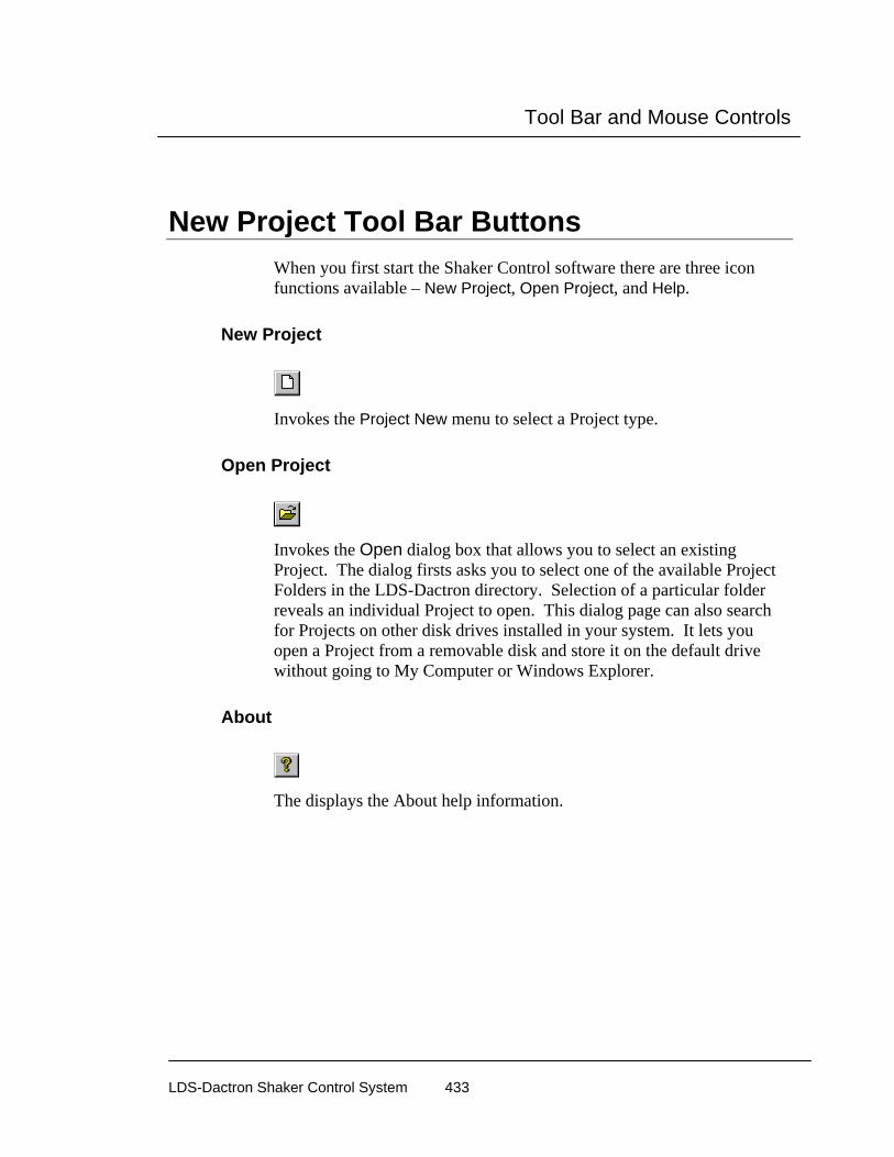
Tool Bar and Mouse Controls
LDS-Dactron Shaker Control System 433
New Project Tool Bar Buttons When you first start the Shaker Control software there are three icon functions available – New Project, Open Project, and Help.
New Project
Invokes the Project New menu to select a Project type.
Open Project
Invokes the Open dialog box that allows you to select an existing Project. The dialog firsts asks you to select one of the available Project Folders in the LDS-Dactron directory. Selection of a particular folder reveals an individual Project to open. This dialog page can also search for Projects on other disk drives installed in your system. It lets you open a Project from a removable disk and store it on the default drive without going to My Computer or Windows Explorer.
About
The displays the About help information.

Tool Bar and Mouse Controls
LDS-Dactron Shaker Control System 434
Global Tool Bar Buttons Global Tool Bar buttons provide direct access to functions that are available in all applications.
Save Project File
Saves an open project. You must have used Save As or have a previously saved file open for this function to operate.
One- Pane
Creates a One-Pane window.
Select Contents
Invokes the Contents dialog box for the active Pane.
Add Cursor
Places a cursor in the middle of the active Pane. One or two cursors may be placed into each pane.
Delete Cursor
Removes cursors from the active Pane in the order of placement.

Tool Bar and Mouse Controls
LDS-Dactron Shaker Control System 435
Add Text Box
Allows you to add a text box on the active Pane. When you select this button, the normal mouse pointer changes to a cross-hair cursor. Click and hold the left mouse button at one corner of the Pane. Holding the left mouse button, drag to create an annotation box. This box cannot be resized later so make sure it’s big enough for your text. (The box can always be moved to different location in the Pane.) When you release the left mouse button, a character insertion marker appears in the upper left-hand corner of the box you just created.
Zoom Out
Zoom Outs to the previous scale settings on a Pane after you have performed at least one Zoom In.
Window Selector
Lists the available Windows. This selector field lets you switch between Windows without going to the Window menu.
Set Demand Level
Invokes the Set Level dialog box to change the excitation level during a test run.
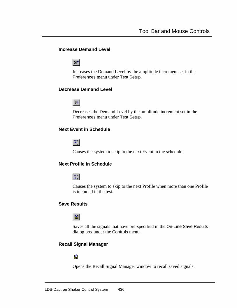
Tool Bar and Mouse Controls
LDS-Dactron Shaker Control System 436
Increase Demand Level
Increases the Demand Level by the amplitude increment set in the Preferences menu under Test Setup.
Decrease Demand Level
Decreases the Demand Level by the amplitude increment set in the Preferences menu under Test Setup.
Next Event in Schedule
Causes the system to skip to the next Event in the schedule.
Next Profile in Schedule
Causes the system to skip to the next Profile when more than one Profile is included in the test.
Save Results
Saves all the signals that have pre-specified in the On-Line Save Results dialog box under the Controls menu.
Recall Signal Manager
Opens the Recall Signal Manager window to recall saved signals.
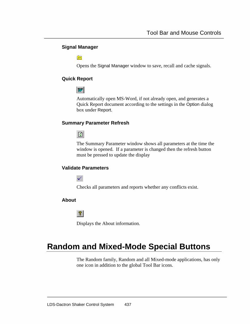
Tool Bar and Mouse Controls
LDS-Dactron Shaker Control System 437
Signal Manager
Opens the Signal Manager window to save, recall and cache signals.
Quick Report
Automatically open MS-Word, if not already open, and generates a Quick Report document according to the settings in the Option dialog box under Report.
Summary Parameter Refresh
The Summary Parameter window shows all parameters at the time the window is opened. If a parameter is changed then the refresh button must be pressed to update the display
Validate Parameters
Checks all parameters and reports whether any conflicts exist.
About
Displays the About information.
Random and Mixed-Mode Special Buttons The Random family, Random and all Mixed-mode applications, has only one icon in addition to the global Tool Bar icons.

Tool Bar and Mouse Controls
LDS-Dactron Shaker Control System 438
Reset Averaging
Resets the Averager function and initiates a re-average of all spectra. The number of averages is preset in the Test page of the Control Parameters menu under Test Setup.
Sine and RSTD Special Buttons The Sine family, Sine and RSTD, have seven icons in addition to the global Tool Bar icons.
Sweep Down
Causes the sine drive signal to sweep in the direction of decreasing frequency.
Sweep Up
Causes the sine drive signal to sweep in the direction of increasing frequency.
Set Frequency
Allows you to set the sine drive frequency. The sine output gradually ramps down in amplitude while at the current frequency. It then shifts to the new frequency and ramps up in amplitude. After it ramps to the demand level, it will hold the sweep until you release it.
Decrease Frequency
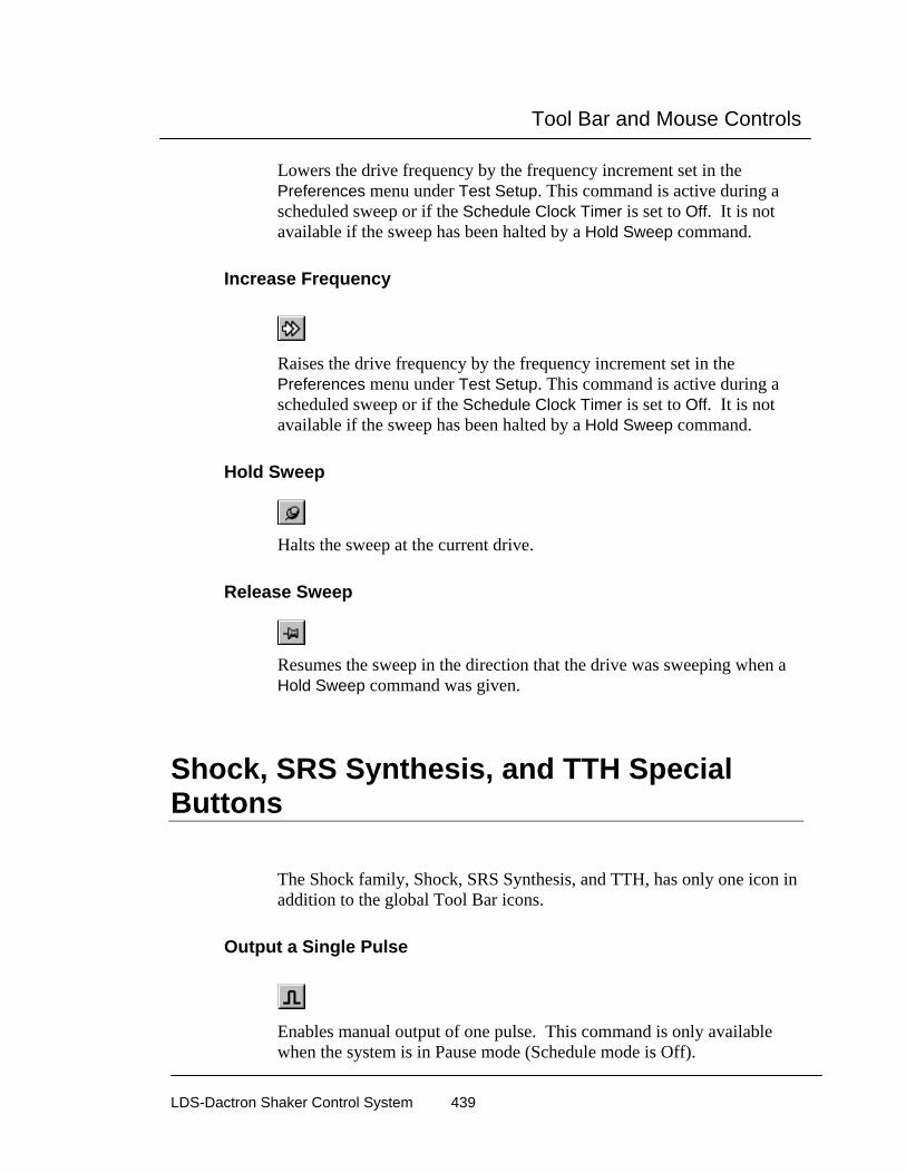
Tool Bar and Mouse Controls
LDS-Dactron Shaker Control System 439
Lowers the drive frequency by the frequency increment set in the Preferences menu under Test Setup. This command is active during a scheduled sweep or if the Schedule Clock Timer is set to Off. It is not available if the sweep has been halted by a Hold Sweep command.
Increase Frequency
Raises the drive frequency by the frequency increment set in the Preferences menu under Test Setup. This command is active during a scheduled sweep or if the Schedule Clock Timer is set to Off. It is not available if the sweep has been halted by a Hold Sweep command.
Hold Sweep
Halts the sweep at the current drive.
Release Sweep
Resumes the sweep in the direction that the drive was sweeping when a Hold Sweep command was given.
Shock, SRS Synthesis, and TTH Special Buttons
The Shock family, Shock, SRS Synthesis, and TTH, has only one icon in addition to the global Tool Bar icons.
Output a Single Pulse
Enables manual output of one pulse. This command is only available when the system is in Pause mode (Schedule mode is Off).

Tool Bar and Mouse Controls
LDS-Dactron Shaker Control System 440
LTH Special Buttons LTH has only one icon in addition to the global Tool Bar icons.
Set Update H Ratio
Sets the feedback gain for the system transfer function calculation. This value ranges from zero to 0.5. A value of zero inhibits any updating of the transfer function after the pre-test. Any value greater than zero causes the transfer function to be updated during the test based on the latest control loop. If the H Update Ratio is set to 0.5, then a new transfer function is calculated by equally weighting the old transfer function and the transfer function from the latest control loop. Typical H Update Ratio values are from 0.1 to 0.35. If the shaker system or test article is highly non-linear, then it may be necessary to use a value near to 0.5 to enhance control accuracy. Caution should be used, however, as a very high value for H Update Ratio can degrade the control accuracy under some conditions.
Waveform Editor Special Buttons LTH has only one icon in addition to the global Tool Bar icons.
Import Profile
This icon opens the Import Profile from File dialog to load a waveform from a disk file.
Save LTH Profile
Saves the compensated waveform to a disk file for use in the LTH program.
Save Spectrum Signal

Tool Bar and Mouse Controls
LDS-Dactron Shaker Control System 441
Saves the PSD of the compensated waveform to a disk file for use in the LTH program as the pre-test profile.
Compensation Template
This button invokes the Compensation Template dialog to set up the compensation operations that are to be applied to the waveform.
Splice
This icon applies a splice fit between segments that adjoin each other after a paste operation. The splice ensures a smooth transition without discontinuity at the boundary of the two segments.
Cut
This icon cuts the highlighted segment (between the two plot cursors) out of the waveform.
Copy
This icon makes a copy of the highlighted waveform segment.
Paste Left, Paste Right
These icons paste a copied waveform segment to the right or the left of the plot cursor.
Undo
This button undoes the prior compensation or waveform edit operation.
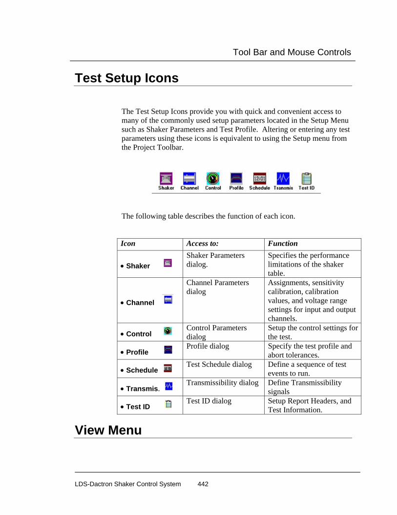
Tool Bar and Mouse Controls
LDS-Dactron Shaker Control System 442
Test Setup Icons
The Test Setup Icons provide you with quick and convenient access to many of the commonly used setup parameters located in the Setup Menu such as Shaker Parameters and Test Profile. Altering or entering any test parameters using these icons is equivalent to using the Setup menu from the Project Toolbar.
The following table describes the function of each icon. Icon Access to: Function
• Shaker Shaker Parameters dialog.
Specifies the performance limitations of the shaker table.
• Channel
Channel Parameters dialog
Assignments, sensitivity calibration, calibration values, and voltage range settings for input and output channels.
• Control Control Parameters dialog
Setup the control settings for the test.
• Profile Profile dialog Specify the test profile and
abort tolerances.
• Schedule Test Schedule dialog Define a sequence of test
events to run.
• Transmis. Transmissibility dialog Define Transmissibility
signals
• Test ID Test ID dialog Setup Report Headers, and
Test Information.
View Menu

Tool Bar and Mouse Controls
LDS-Dactron Shaker Control System 443
The View menu on the Project Toolbar allows you select which toolbars and panels will be viewable from the Application Screen. To enable or disable a view, click on the corresponding text from the menu to either check or uncheck that option. Note that all panels and toolbars (except for the Project bar) may be moved to different locations on the screen by drag-and-drop.
View menu
• Tool Bar toggles on and off the Toolbar from view.
Tool Bar • Status Bar toggles on and off the Status Bar from view.
Status Bar
• Control Panel toggles on and off the Control Panel from view.
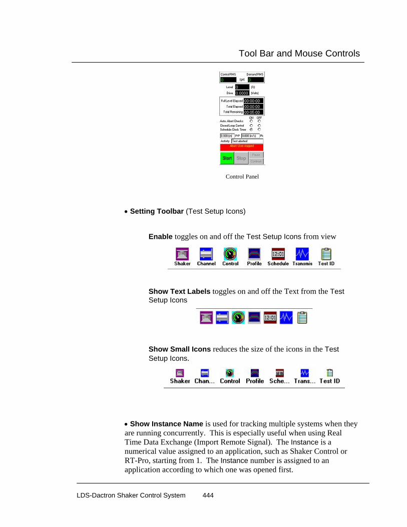
Tool Bar and Mouse Controls
LDS-Dactron Shaker Control System 444
Control Panel
• Setting Toolbar (Test Setup Icons)
Enable toggles on and off the Test Setup Icons from view
Show Text Labels toggles on and off the Text from the Test Setup Icons
Show Small Icons reduces the size of the icons in the Test Setup Icons.
• Show Instance Name is used for tracking multiple systems when they are running concurrently. This is especially useful when using Real Time Data Exchange (Import Remote Signal). The Instance is a numerical value assigned to an application, such as Shaker Control or RT-Pro, starting from 1. The Instance number is assigned to an application according to which one was opened first.
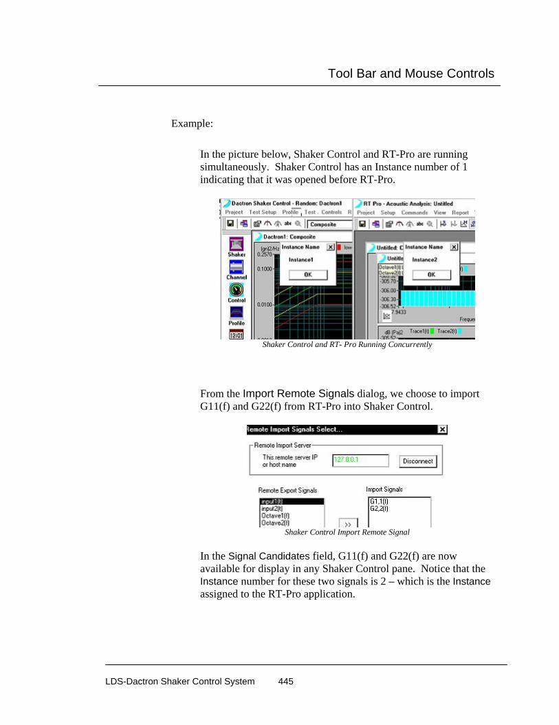
Tool Bar and Mouse Controls
LDS-Dactron Shaker Control System 445
Example:
In the picture below, Shaker Control and RT-Pro are running simultaneously. Shaker Control has an Instance number of 1 indicating that it was opened before RT-Pro.
Shaker Control and RT- Pro Running Concurrently
From the Import Remote Signals dialog, we choose to import G11(f) and G22(f) from RT-Pro into Shaker Control.
Shaker Control Import Remote Signal
In the Signal Candidates field, G11(f) and G22(f) are now available for display in any Shaker Control pane. Notice that the Instance number for these two signals is 2 – which is the Instance assigned to the RT-Pro application.

Tool Bar and Mouse Controls
LDS-Dactron Shaker Control System 446
Shaker Control Signal Candidates
Mouse Controls Most user-interface operations involve use of the mouse. MS Windows Tools, setup menus, test control commands, and window manipulations require mouse operations. Standard functions such as move, size, maximize, minimize, iconize and close will not be explained here.
LDS-Dactron’s Shaker Control System, uses the mouse for a variety of special functions. The application software employs both the left and right mouse buttons. This section explains the special uses of the mouse by the Shaker Control applications.
It is assumed here that you are familiar with standard mouse functions such as click or click and drag. In the Shaker Control applications the following conventions are used:
• Click always implies pressing the left mouse button once unless the right mouse button is explicitly specified.
• Drag implies moving the mouse with the left button depressed.
Working with Windows and Panes Most of your work with the LDS-Dactron Shaker Control System will probably be with the Composite and Customized Windows and Panes. These displays have special Tool Bar and Mouse controls.
Changing Y and X Scales A number of display dialog boxes can be accessed directly by pointing at an area on the screen and clicking. You can enable the Change Y Limit
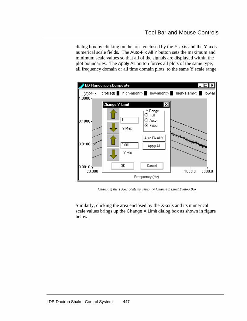
Tool Bar and Mouse Controls
LDS-Dactron Shaker Control System 447
dialog box by clicking on the area enclosed by the Y-axis and the Y-axis numerical scale fields. The Auto-Fix All Y button sets the maximum and minimum scale values so that all of the signals are displayed within the plot boundaries. The Apply All button forces all plots of the same type, all frequency domain or all time domain plots, to the same Y scale range.
Changing the Y Axis Scale by using the Change Y Limit Dialog Box
Similarly, clicking the area enclosed by the X-axis and its numerical scale values brings up the Change X Limit dialog box as shown in figure below.

Tool Bar and Mouse Controls
LDS-Dactron Shaker Control System 448
Changing the X Axis Scale by Using the Change X Limit Dialog Box
Zoom In To zoom in on a particular area of a Pane, use click and drag to create a “zoom-in” box. The data displayed within the box you define is magnified. First, position the mouse pointer over the plot, then click and hold the left mouse button down. This action establishes one corner of the zoom-in box. Then drag the mouse to draw a box covering the portion of the plot to magnify. Then release the left mouse button. This displays the “zoom-in” box you’ve created and the system prompts you to “Click to zoom-in”. Click once in the “zoom-in” box and the display is then redrawn with new X- and Y-axis scale ranges.
By Zooming In, you activate the Zoom Out icon on the Tool Bar and the Zoom Out command in the Pane menu.

Tool Bar and Mouse Controls
LDS-Dactron Shaker Control System 449
Using the Mouse to Define a Zoom-In Box
Zoomed-In Display
Tool Bar and Mouse Controls
LDS-Dactron Shaker Control System 450
Cursor Movement Both coarse and fine positioning controls are available to move the plot cursor:
Coarse cursor movement – Place the mouse pointer over the plot cursor. When you see the mouse pointer change to a pointing hand symbol, click and drag to reposition the cursor. Upon release of the left mouse button, the cursor stays put and the mouse resumes normal operation.
Fine cursor movement – Use the left and right keyboard arrows to position the cursor. When two cursors are displayed, you must first make the cursor that you want to move the active cursor. You do this by placing the mouse pointer over this cursor and clicking.
Synchronized cursor movement in multiple panes - To move cursors on two or more, separate panes, place a cursor on the desired panes, then hold down the Shift key and use the keyboard arrows to move the cursor. All cursors on panes with the same type of signals (all time domain or frequency domain signals) will follow the cursor on the active pane.
Synchronized cursor movement with dual cursors To move dual cursors synchronized while maintaining the same space between them, hold down the Control key and click on the first cursor so that both cursors are selected (highlighted in red). Use the keyboard arrows to move the cursors. To disable synchronized dual cursor movement and move only one cursor, hold down the Control key and deselect one of the dual cursors (deselected cursor is highlighted in green).
To change the active data trace for cursor readout, use the up and down keyboard arrows to scroll to the desired signal.

Tool Bar and Mouse Controls
LDS-Dactron Shaker Control System 451
Moving the Cursor
Moving the Cursor Readout You may position the Cursor Readout Box wherever you wish. Simply click and drag the box to a new position in the pane. You can even move it off the data area and onto the frame area of the Pane.
Moving the Cursor Readout Box

Tool Bar and Mouse Controls
LDS-Dactron Shaker Control System 452
Cursor Readout for RMS and Power When using dual cursors, the cursor readout shows the RMS and Power values for the portion of the spectrum between the cursor markers. As the dual cursor markers are moved, the RMS and Power readouts will change.
RMS and Power Value Readouts when Using Dual Cursors.
Adding Cursor Marks To tag points on a data trace, first position the cursor and then press Ctrl M. Use the up arrow key to activate a different trace for mark insertion. Click and drag the mark box to any location desired on the display pane.

Tool Bar and Mouse Controls
LDS-Dactron Shaker Control System 453
Use Add Mark to Tag Data Traces
Peak and Valley Cursors Use the Add Peak Cursor or Add Valley Cursor under the Cursor menu to automatically find and mark peaks or valleys. The peak/valley marks and the X-Y readout box applies to the active trace. You can change the active trace via the up or down arrow keys.

Tool Bar and Mouse Controls
LDS-Dactron Shaker Control System 454
Add Peak Cursor Automatically Finds and Marks Peaks
Add Valley Cursor Automatically Finds and Marks Valleys
Quality Factor “Q” and Damping Factor Readout The Q Factor can be automatically calculated from a spectrum plot by selecting Calculate Q Factor with Normal Cursor from the Cursor menu. This option is only available when a normal cursor is added to a pane.

Tool Bar and Mouse Controls
LDS-Dactron Shaker Control System 455
Move the normal cursor near a peak in the spectrum plot and the text readout will display the Q Factor and the percent damping, computed from:
Q Factor = fc/(f2-f1)
% damping = 1/(2*Q Factor)
Where fc is the center frequency at the peak, f1 and f2 are the half power points computed from 3 dB below fc.
Calculating the Quality Factor “Q” by using the Single Cursor.
Harmonic Cursor Add Harmonic Cursor in the Cursor menu places harmonic cursors in the active pane. Use the mouse to set the fundamental frequency by clicking and dragging the red cursor. For multiple overlaid signals, you can use the up/down arrow keys to select the data trace to use for harmonic cursor display. The total harmonic distortion (THD) is also calculated when this feature is activated.
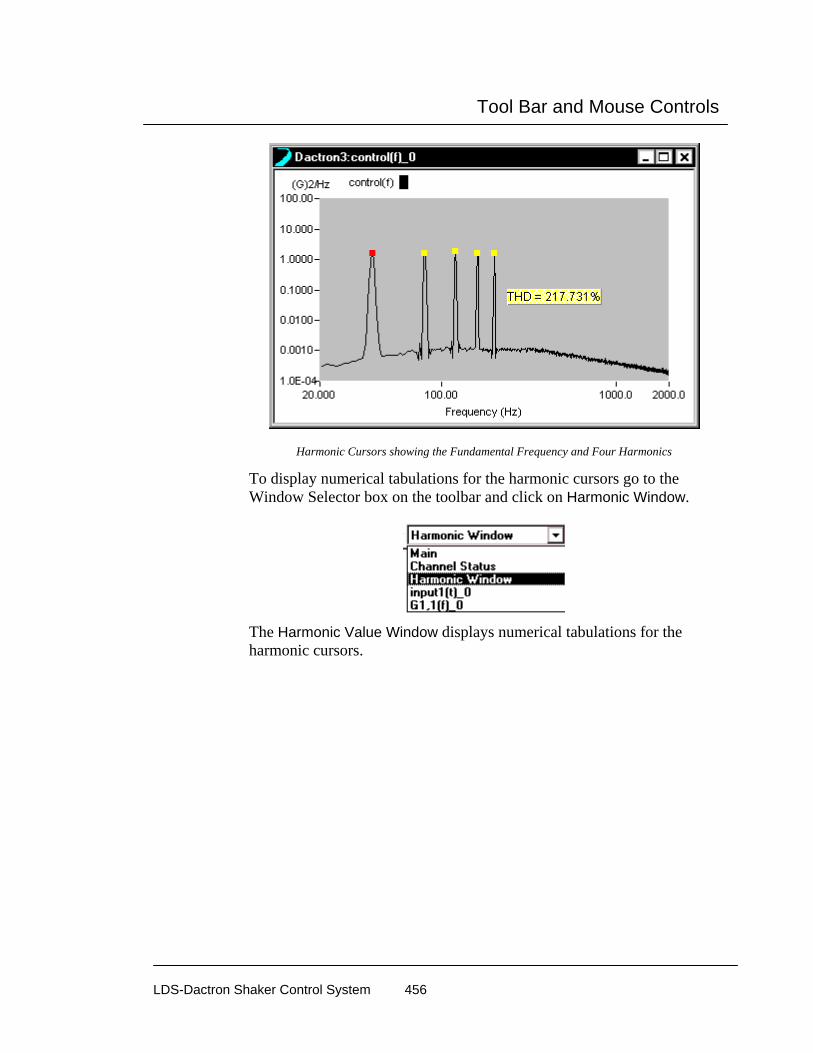
Tool Bar and Mouse Controls
LDS-Dactron Shaker Control System 456
Harmonic Cursors showing the Fundamental Frequency and Four Harmonics
To display numerical tabulations for the harmonic cursors go to the Window Selector box on the toolbar and click on Harmonic Window.
The Harmonic Value Window displays numerical tabulations for the harmonic cursors.

Tool Bar and Mouse Controls
LDS-Dactron Shaker Control System 457
Harmonic Cursor Windows Shows Tabulated Values
Right mouse click in the Harmonic Value Window to open a pop-up menu.
Select Copy to place a text version of the harmonic values table on the clipboard. The text version of the table can easily be pasted into, for example, Word or Excel.
Select Report to automatically generate a one page report in Word that contains the harmonic values table.
Display Mode controls the way numbers are displayed. For example, the value 0.035 can be displayed as:
0.035 floating point description
3.5e-3 scientific description
35m short note description
The Float format is straightforward and easy to understand. However, for extremely small or big values, it requires many digits to represent data values. In this case, use the scientific or short-note description. When Float is selected in the Display Mode menu a 4th menu choice, Digits, is available. Use this option to select the number of digits displayed.
Tool Bar and Mouse Controls
LDS-Dactron Shaker Control System 458
Scientific uses a mantissa (the numbers before the “e”) and an exponent (the numbers after “e”) for the data display. The number “3.5e-3” means 3.5 ×10⁻³.
Short-Note uses the following industry conventions to describe a value:
G stands for Giga and is 10 to the ninth power.
M stands for Mega and is 10 to the sixth power.
k stands for kilo and is 10 to the third power.
m stands for milli and is 10 to the minus third power.
u stands for micro and is 10 to the minus sixth power.
n stands for nano and is 10 to the minus ninth power.
p stands for pico and is 10 to the minus twelfth power.
Mix will use a combination of Float and Short-Note depending on the values in the table.
Adding Annotation and Annotation Box Movement To add annotation to a pane, click the Add Text icon or use the Add Annotation selection in the Pane menu. This will invoke an insertion crosshair pointer, which marks one corner of the Annotation Box. Click and drag to form a text entry box for your annotation.
Once the size of the box is established, it cannot be changed. However, you can cut and paste annotation from one box to another. To do this, point inside the Annotation Box and either click the right mouse button then select Edit from the pop-up menu or perform a double-click operation. To delete an Annotation Box you can either right-click inside the box then select Remove or you can first delete the text within the box then a simple click by either the left or right mouse button elsewhere in the window will remove the Annotation Box.
The Annotation Box always invokes the word wrap feature. Lines of text will fit inside the box until the volume of text exceeds the capacity of the box. When the entered text exceeds the size of the box, the annotation will start to disappear outside the top of the box. In this the case, either create a larger box and paste the text into it using the process explained above or you can simply click once on the box then re-size it using your mouse.
Note: There is no spell checker for the Annotation Box. But you can create text in MS-Word, spell-check it there, then cut and paste it into your Annotation Box.

Tool Bar and Mouse Controls
LDS-Dactron Shaker Control System 459
Annotation Entry Box
Right click on the annotation text box to invoke the following pop-up menu:
Property invokes the Text Parameters dialog which you can use to edit the text, change the font, or change the font color.
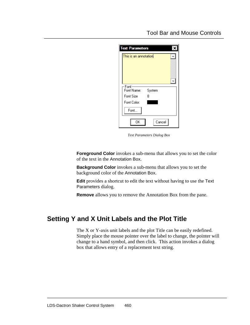
Tool Bar and Mouse Controls
LDS-Dactron Shaker Control System 460
Text Parameters Dialog Box
Foreground Color invokes a sub-menu that allows you to set the color of the text in the Annotation Box.
Background Color invokes a sub-menu that allows you to set the background color of the Annotation Box.
Edit provides a shortcut to edit the text without having to use the Text Parameters dialog.
Remove allows you to remove the Annotation Box from the pane.
Setting Y and X Unit Labels and the Plot Title The X or Y-axis unit labels and the plot Title can be easily redefined. Simply place the mouse pointer over the label to change, the pointer will change to a hand symbol, and then click. This action invokes a dialog box that allows entry of a replacement text string.

Tool Bar and Mouse Controls
LDS-Dactron Shaker Control System 461
Changing the Legend Title by Using the Title Area Dialog Box
Window Pane Border Movement You can change the relative sizes of individual panes within a window by moving the divider bars. To do so position the mouse pointer over a Pane divider bar. A Resize icon will appear. A uni-directional Resize icon allows the divider bar to be dragged horizontally or vertically. To do a combined vertical and horizontal movement, position the mouse pointer over the intersection of the horizontal and vertical dividers bars and then drag the bi-directional Resize icon.
The figure below shows the two different tools. See also Section 6, “Create Screens and Reports.”

Tool Bar and Mouse Controls
LDS-Dactron Shaker Control System 462
Moving Window Pane Border
Accessing the Pane Contents Dialog Box To access the Contents dialog box for any Pane, position the mouse pointer over the pane and click the right mouse button. Remember the Contents dialog only affects the active Pane. You may want to use the Pane border movement tools to enlarge the relative size of the Pane prior to accessing the Contents dialog so that changes are easily seen.
Working with the Profile Block Diagram The Profile Block Diagram shows the order of execution of profiles and their associated schedules. In this window, be sure to watch for the asterisk * next to the functional block name.
The * indicates the active blocks on the Profile Block Diagram. You can activate other blocks by clicking on them. A double-click on a Profile Block will invoke the Profile dialog box. A double-click on a Schedule Block will invoke the Schedule page.

Tool Bar and Mouse Controls
LDS-Dactron Shaker Control System 463
An * Indicates the Active Profile and Schedule in the Profile Block Diagram Window

Special Displays and Functions
LDS-Dactron Shaker Control System 464
8 Special Displays and Functions
Waterfall Displays
How to Set Up a Waterfall Display A Waterfall is a plot of a time function or frequency based function such as input1(t) or G1,1(t), versus a third axis: time, event number, or another measured signal. When an Event Waterfall is requested, the data is buffered on the PC after it is transferred from the DSP. Therefore, the accuracy of the third axis cannot be guaranteed.
The figure below shows how the PC stores each transient event in Event 3D mode. The ignored portion of data will be acceptable to the user as long as all the transient events are captured and stored.
Spectral transform
Trasfer 2D signal to PCand store it into 3D array
DSP System
PC
time
transient capture
ignored ignored
initiate next capture
An Event Waterfall can be defined by selecting Waterfall Request from Special Signals under the Test Setup menu.

Special Displays and Functions
LDS-Dactron Shaker Control System 465
From the Waterfall Setup dialog, you can select the signal to be displayed as a waterfall from the Signal Candidates field and also define the third axis in the “Associate Waterfall with” area. Once a waterfall plot has been created using the Waterfall Setup, you can display it in a Waterfall Window or Waterfall plus Slice Window.
Signal Candidates displays a list of the signals that can be selected for a waterfall display. To select a signal from the Signal Candidates list,
Special Displays and Functions
LDS-Dactron Shaker Control System 466
highlight the signal by clicking on the text and click >> to move it to the Selected Signals list. Conversely, use the << button to remove any undesired signal from the selected list. Selected Signals shows the signals that will be computed for waterfall display. To remove a signal from the Selected Signals list, highlight the signal by clicking on the text and use the << button to remove the undesired signal from the Selected Signals list. Number of slices defines the number of plots that will be displayed on the third axis of the waterfall. Scrollable defines the action when the data reaches the end of the event axis. When the scrollable option is enabled then the last dataset scrolls off the frame and is replaced by the next frame so that the data continuously scrolls across the waterfall plot. When this option is disabled then when the last dataset reaches the end of the event axis the waterfall display is frozen and the data stops updating so that a fixed number of events can be captured without stopping the measurement. “Associate the Waterfall with” defines what data will be used to represent the third axis of the waterfall. The choices are Time, Event Sequence Number, and Measurement Quantity.
Associate the Waterfall with:
1) Time
Time waterfall data is buffered on the PC memory instead of the DSP memory and therefore the quantity of data can be significantly larger. The quantity of data is defined by the number of slices and the number of frequency lines and is limited only by the PC RAM memory. This feature can be used to display up to 500 slices over an unlimited time span. Also the acquisition is not guaranteed to be in real-time because the communication between the PC and the DSP is not a real-time process.

Special Displays and Functions
LDS-Dactron Shaker Control System 467
Time Event Waterfall can display many more slices than the Real-Time waterfall because the data is buffered in the PC memory not the DSP memory. To compute a time event waterfall the Time option must be selected. Total Time Duration defines the length of the waterfall display in seconds. The time resolution between slices is defined by the number of slices and the total time duration.
2) Event Sequence Number
Event Sequence Number should be used with a triggered event such as an impact or other transient capture. The waterfall will display one frame of data, either time or frequency data, on each slice. This is useful for examining the effect of changes in sensor or impact location or impact force. The third axis is labeled as Event number, e.g., 1, 2, 3…

Special Displays and Functions
LDS-Dactron Shaker Control System 468
Event Waterfalls are useful for displaying multiple triggered events such as impacts from hammer blows to study the variation with location and force.
3) Measurement quantity as reference
Measurement quantity as reference allows the use of any measured signal to be used as the reference so that the data will be displayed as a function of the secondary measured signal. Note that this signal can increase and decrease with time and therefore the third axis will be updated as the Z-reference varies. Typical applications include studying the effect of variations of temperature, pressure, strain, etc..
Z-Reference defines the input channel that will be used as the reference. This channel will be represented on the thirds axis of the waterfall plot. Value defines how the input from the Z-Reference is evaluated. The choices are Mean, Peak and RMS. Low Limit defines the lowest value of the reference signal that will be plotted on the waterfall plot.
High Limit defines the highest value of the reference signal that will be
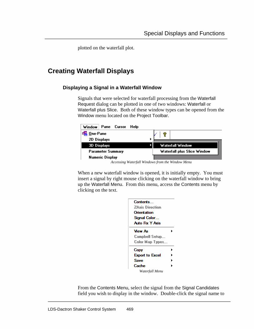
Special Displays and Functions
LDS-Dactron Shaker Control System 469
plotted on the waterfall plot.
Creating Waterfall Displays
Displaying a Signal in a Waterfall Window
Signals that were selected for waterfall processing from the Waterfall Request dialog can be plotted in one of two windows: Waterfall or Waterfall plus Slice. Both of these window types can be opened from the Window menu located on the Project Toolbar.
Accessing Waterfall Windows from the Window Menu
When a new waterfall window is opened, it is initially empty. You must insert a signal by right mouse clicking on the waterfall window to bring up the Waterfall Menu. From this menu, access the Contents menu by clicking on the text.
Waterfall Menu
From the Contents Menu, select the signal from the Signal Candidates field you wish to display in the window. Double-click the signal name to

Special Displays and Functions
LDS-Dactron Shaker Control System 470
add it to the Selected Signal list. Or click on a signal name and use the >> button. To remove a signal from the Selected Signal list, click on the unwanted signal name in the Selected Signals list and then click on the << button.
Waterfall plus Slice Window Waterfall plus Slice Window brings up an empty two-pane window from where you can select a signal to be processed and displayed. The lower pane displays the Waterfall plot and the upper pane displays a 2D slice of the Waterfall plot as either a X-Slice or a Z-Slice. The X-Slice is the 2D plane intersecting the x-axis and the Z-Slice intersects the z-axis.

Special Displays and Functions
LDS-Dactron Shaker Control System 471
To the change slice that is displayed in the slice pane, right mouse click on the slice pane to bring up the Slice Menu. Then select the slice you wish to view.
Slice Menu
Waterfall Menu Controls
Contents directs you to the Contents Menu. From this menu, you can select signals for waterfall processing/display, define Signal Colors, define displayed Coordinates (x-y-z scale), and define General display options. Orientation allows you to define the X-Y-Z viewing angle of the waterfall plot. Immediately after selecting Orientation, use the mouse to change the viewing angle of the waterfall plot. Left mouse click to set the viewing angle.

Special Displays and Functions
LDS-Dactron Shaker Control System 472
Line Propeties provides settings for the line color and thickness for each individual signal. Auto Fit Y Axis View As provides the following options: Waterfall, Campbell, Color Map.
Waterfall returns the waterfall display to Normal View (3D-display). Campbell is not used for the Shaker Control applications. Color Map displays the waterfall plot as a 2-D color intensity map, where you view the waterfall plot in the X-Z plane and the color corresponds to amplitude in the y-axis. This feature can only be selected after the test has been stopped.
Copy provides the following options: Pane Bitmap and All Signals. Pane Bitmap copies a bitmap image of the current pane into the Windows Clipboard. This image can then be pasted into any Windows application such as Word or an email program. All Signals allows the user to copy a signal to the Windows Clipboard. This is a fast and convenient method to export data into other Windows software such as Excel and Word. Export to Excel copies the values of the selected, or all signals to an Excel spreadsheet. If Excel is not launched then the application is automatically launched. A new spreadsheet is opened and the values are copied into a formatted table. The data is also dynamically linked to the Shaker Control application so that as the measurement continues, or is started again, the values in the Excel spreadsheet are continuously updated. This feature allows advanced calculations that are not available in the Shaker Control software to be performed within the Excel software. Save provides the following options: Save Slice and All Signals. All Signals will save all signals in the pane to disk. Save Slice invokes the following dialog box.
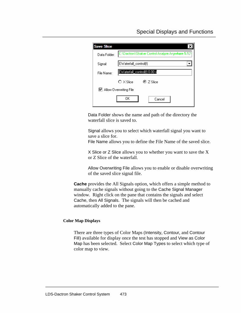
Special Displays and Functions
LDS-Dactron Shaker Control System 473
Data Folder shows the name and path of the directory the waterfall slice is saved to. Signal allows you to select which waterfall signal you want to save a slice for. File Name allows you to define the File Name of the saved slice. X Slice or Z Slice allows you to whether you want to save the X or Z Slice of the waterfall. Allow Overwriting File allows you to enable or disable overwriting of the saved slice signal file.
Cache provides the All Signals option, which offers a simple method to manually cache signals without going to the Cache Signal Manager window. Right click on the pane that contains the signals and select Cache, then All Signals. The signals will then be cached and automatically added to the pane.
Color Map Displays There are three types of Color Maps (Intensity, Contour, and Contour Fill) available for display once the test has stopped and View as Color Map has been selected. Select Color Map Types to select which type of color map to view.
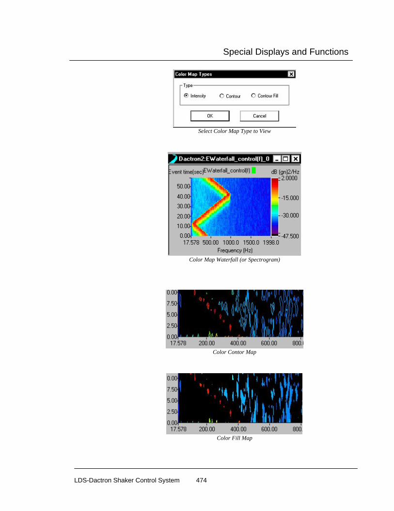
Special Displays and Functions
LDS-Dactron Shaker Control System 474
Select Color Map Type to View
Color Map Waterfall (or Spectrogram)
Color Contor Map
Color Fill Map

Special Displays and Functions
LDS-Dactron Shaker Control System 475
Waterfall Cursor
When a cursor is added to a Waterfall plot, two independently controlled cursors are displayed. The arrow keys move each cursor – up and down arrow keys control one cursor and the left and right arrow keys control the other. The numerical information corresponding to the intersection of the two cursors is displayed in the Waterfall pane. Note that the slice that is viewed in the Slice pane will match to the cursor location in the Waterfall pane.
Waterfall Cursor used to select Slice Displayed

Special Displays and Functions
LDS-Dactron Shaker Control System 476
Signal Viewer Utility The Signal Viewer utility provides the capability to display data by just doubling clicking on the signal file name. To install this utility insert the Shaker Control software CD into the CD drive and then from the main page select Enabling Applications. Then click on the Signal Viewer menu item.
Signal Viewer utility installation menu
Once Signal Viewer has been installed you can open Windows Explorer, find the signal files that you want to view, and then just double click on the file name to open the data display. The display attributes may be changed by using the display mouse commands. For example, putting the mouse pointer over the Y scale and left clicking invokes the Change Y Limit dialog as shown in the picture below.
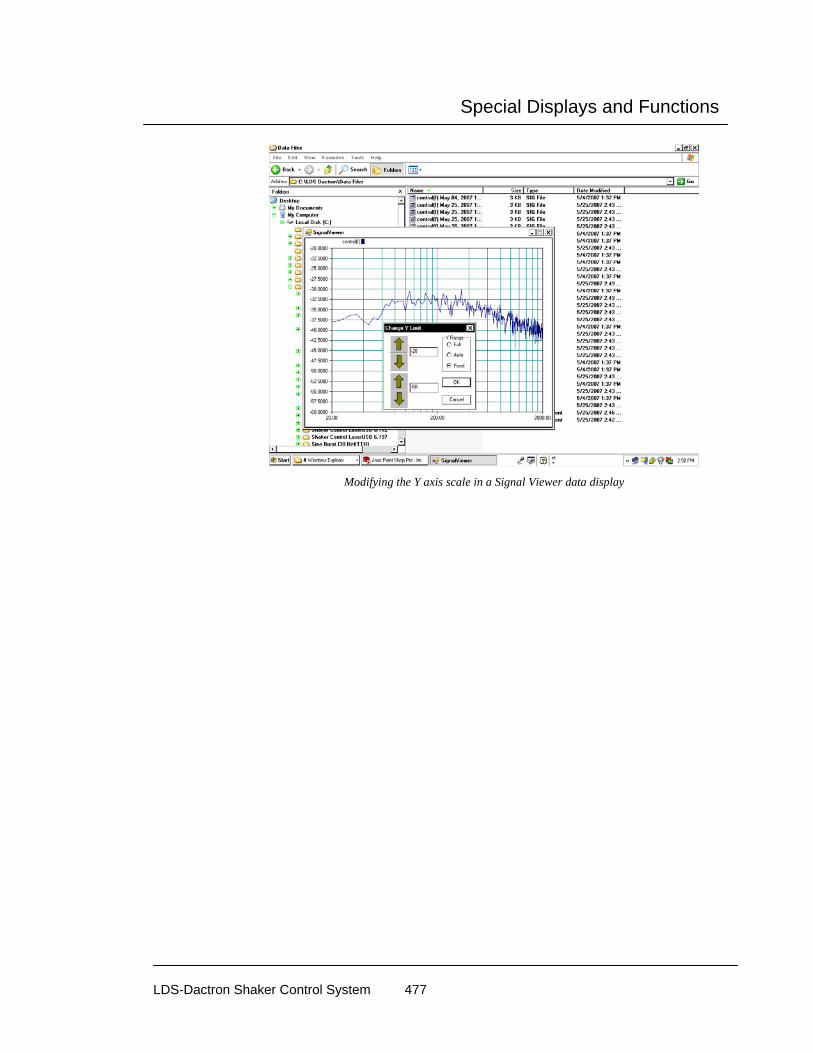
Special Displays and Functions
LDS-Dactron Shaker Control System 477
Modifying the Y axis scale in a Signal Viewer data display

Special Displays and Functions
LDS-Dactron Shaker Control System 478
PC Camera
The PC Camera allows you to display live camera images within a special window in the Shaker Control applications. To install this utility insert the Shaker Control software CD into the CD drive and then from the main page select Enabling Applications. Then click on the Camera menu item.
PC Camera installation menu
Once the Camera utility has been installed use the flowing procedure to set up the PC camera operation:
1. Install a PC camera, including the supplier’s software, and verify the operation of the camera.
2. From within a Shaker Control application, or from the Start-Up page, select Camera from the View menu.

Special Displays and Functions
LDS-Dactron Shaker Control System 479
3. After selecting Camera, the special camera window will appear and show images from the connected camera. Note: The software does not currently support networked camera operation
4. The camera window can be moved to any convenient position on the screen including under the Control Panel.
Camera showing a live image
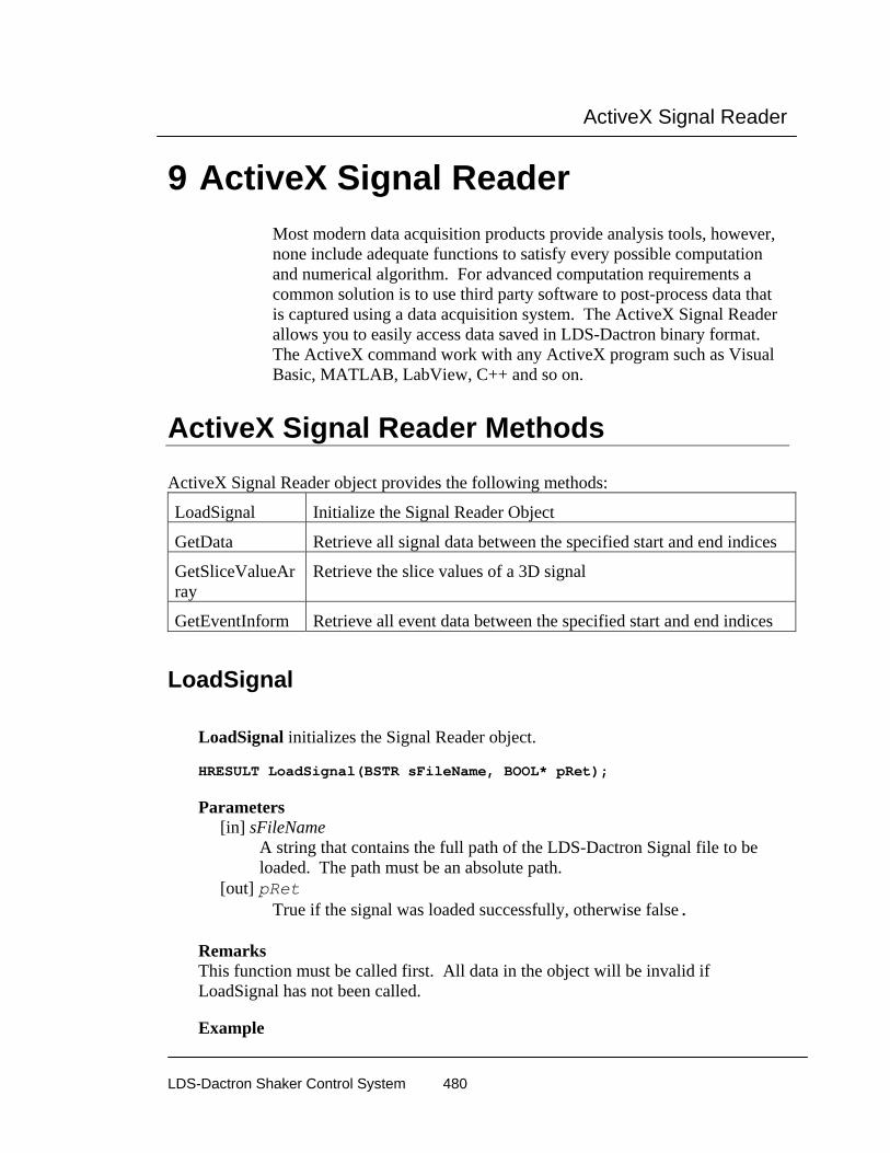
ActiveX Signal Reader
LDS-Dactron Shaker Control System 480
9 ActiveX Signal Reader Most modern data acquisition products provide analysis tools, however, none include adequate functions to satisfy every possible computation and numerical algorithm. For advanced computation requirements a common solution is to use third party software to post-process data that is captured using a data acquisition system. The ActiveX Signal Reader allows you to easily access data saved in LDS-Dactron binary format. The ActiveX command work with any ActiveX program such as Visual Basic, MATLAB, LabView, C++ and so on.
ActiveX Signal Reader Methods
ActiveX Signal Reader object provides the following methods:
LoadSignal Initialize the Signal Reader Object
GetData Retrieve all signal data between the specified start and end indices
GetSliceValueArray
Retrieve the slice values of a 3D signal
GetEventInform Retrieve all event data between the specified start and end indices
LoadSignal
LoadSignal initializes the Signal Reader object. HRESULT LoadSignal(BSTR sFileName, BOOL* pRet); Parameters [in] sFileName
A string that contains the full path of the LDS-Dactron Signal file to be loaded. The path must be an absolute path.
[out] pRet True if the signal was loaded successfully, otherwise false. Remarks This function must be called first. All data in the object will be invalid if LoadSignal has not been called. Example

ActiveX Signal Reader
LDS-Dactron Shaker Control System 481
Visual C++: See CDacSignalVCDemoDlg::OnLoadsignal() in DacSignalVCDemoDlg.cpp of the VC++ demo project.
Visual Basic: See Sub LoadSignal_Click() in DacSignalVBDemoDlg.frm of the VB demo project.
GetData GetData retrieves all signal data between the specified start and end indices. HRESULT GetData( long nSlice,
long nStart, long nEnd, VARIANT* varBuffer);
Parameters [in] nSlice
The 3D slice number of the data to be retrieved. Use 0 for 2Dsignals. [in] nStart The zero based index of the internal data buffer to be used as the first data point to be retrieved. Typically zero.
[in] nEnd The zero based index of the internal data buffer to be used as the last data point to be retrieved. Typically NumOfSamples-1.
[out] varBuffer An array that contains the signal data.
Remarks The call will fail if the value of nSlice is larger than NumOfSlice, the value of nStart is greater than nEnd, or nStart and/or nEnd are outside the valid indices of the signal data buffer. The signal data for complex signals is organized as follows: Real[i] = varBuffer[i*2], Imaginary[i] = varBuffer[(i*2)+1]
Example Visual C++:
See CDacSignalVCDemoDlg::OnGetData()in DacSignalVCDemoDlg.cpp of the VC++ demo project.
Visual Basic:
See Sub GetDataBuffer_Click() in DacSignalVBDemoDlg.frm of the VB demo project.

ActiveX Signal Reader
LDS-Dactron Shaker Control System 482
GetSliceValueArray GetSliceValueArray retrieves the slice values of a 3D signal.
HRESULT GetSliceValueArray(VARIANT* varBuffer); Parameters
[out] varBuffer An array that contains the slice axis values. E.g. Z[i] = varBuffer[i] Remarks
This function can be used to get the slice values for 3D signals that have evenly spaced slice values and those that do not.
Example Visual C++:
See CDacSignalVCDemoDlg::OnGetslicebuffer() in DacSignalVCDemoDlg.cpp of the VC++ demo project.
Visual Basic:
See Sub SliceData_Click() in DacSignalVBDemoDlg.frm of the VB demo project.
GetEventInform GetEventInform retrieves all event data between the specified start and end
indices. HRESULT GetEventInform(VARIANT* varStartPoints,
VARIANT* varStartTimes, VARIANT* varEventLengths, BOOL* bRet);
Parameters [out] varStartPoints An array that contains the starting index of each event in the signal file. [out] varStartTimess An array that contains the starting time in seconds of each event in the signal file. [out] varEventLengths An array that contains the length in points of each event in the signal file. [out] bRet
True if the data in the arrays is valid. False otherwise.

ActiveX Signal Reader
LDS-Dactron Shaker Control System 483
Remarks All arrays returned are parallel. The start Point, Time, and Length of an event [i] can be retrieved from the arrays as varStartPoints[i], varStartTimes[i], varEventLengths[i].
Example Visual C++:
See CDacSignalVCDemoDlg::OnEventInfo() in DacSignalVCDemoDlg.cpp of the VC++ demo project.
Visual Basic:
See Sub EventInfo_Click() in DacSignalVBDemoDlg.frm of the VB demo project.
ActiveX Signal Reader Properties
ActiveX Signal Reader object provides the following properties: Property Type
Name Description Version Active X object version. 1000
means 1.00 Long
SigVersion Signal version. 1000 means version 1.00
Long
NumOfSamples (Xsize)
Number of Samples Long
DataType (Xstep)
Used to determine if data is real only, or real and imaginary. 1: Y is real data 2: Y is (real, imaginary) data
Long
XaxisBegin The starting X value. Double
XaxisDelta Delta for X axis Double
XaxisSpacingEven (Xincrease)
Defines how X axis values should be calculated. If True, X[i] = X[0]+Delta* i, If False, X[i] = X[0]*power(delta , i)
BOOL
XaxisUnit (Xlabel)
Text label that has been associated with the X axis.
BSTR

ActiveX Signal Reader
LDS-Dactron Shaker Control System 484
LowValidIndex First valid index of the data buffer
Long
HighValidIndex Last valid index of the data buffer
Long
IsRecordingData If true if the signal file contains more than one frame of data.
BOOL
DataFormat Type of signal. (see description of DATAFORMAT for signal type details)
Enum DATAFORMAT
Chan1Dimension Channel dimension (see description of TRANSUNITS for dimension details)
Eunm TRANSUNITS
Chan2Dimension Channel dimension (see description of TRANSUNITS for dimension details)
Eunm TRANSUNITS
SignalName Display name for the signal BSTR
EULabel Display text for the Engineer Unit of the signal.
BSTR
MeasDate Date the signal was measured. Format:
BSTR
MeasTime Time the signal was measured. Format: HH:MM:SS (24hr clock)
BSTR
NumOfSlice (Zsize)
The value is 1 for 2D signals. If the signal is a 3D signal, the value represents the number of slices along the slice axis.
Long
SliceBegin (Zbegin)
Starting value for the slice axis. Double
SliceDelta (Zdelta)
Delta for slice axis. Double
SliceUnit Display units for slice axis. BSTR
SliceSpacingEven (Zincrease)
If True, Z[i] = Z[0]+Delta* i If False, retrieve data from slice data buffer. Also see GetSliceValueArray()
BOOL
NumOfEvent Number of events in a time domain signal.
Long
ChanStatus.IsAvailable
If True, Channel Status values are valid If False, Channel Status values are not valid.
BOOL

ActiveX Signal Reader
LDS-Dactron Shaker Control System 485
ChanStatus.Max Signal Max Float
ChanStatus.Min Signal Min Float
ChanStatus.Mean Signal Mean Float
ChanStatus.Peak Signal Peak Float
ChanStatus.RMS Signal RMS Float
ChanStatus.PSDRMS
Signal PSD RMS Float
Advance.SampRate Rate at which the signal was sampled.
Double
Advance.XallocSize Total size of the X axis buffer. For some signals this number is larger than the value of NumOfSamples.
Long
Advance.AllocSize Total buffer size allocated for the signal. Includes X and Z data.
Long
Advance.Order Order value. Valid only for APSD_RPM and CPSD_RPM signals.
Double
Advance.OrderDelta Internal data is stored as EU2/Order. This value is used a conversion factor to convert the signal data to EU2. Valid only for APSD_RPM and CPSD_RPM signals.
Double
Advance.WindowType
The window function applied to the signal. (see description of WNDTYPE for window type details)
Enum WNDTYPE
Advance.Oct_b Octave number. If Advance.Oct_b = 3, then 1/3 octave.
Long
Advance.Oct_Weight Octave weighting. One of A,B,C,D, Linear, or none.
Enum WEIGHTING
Advance.Oct_HighFreq
High end of the analysis range Float
Advance.Oct_LowFreq
Low end of the analysis range Float
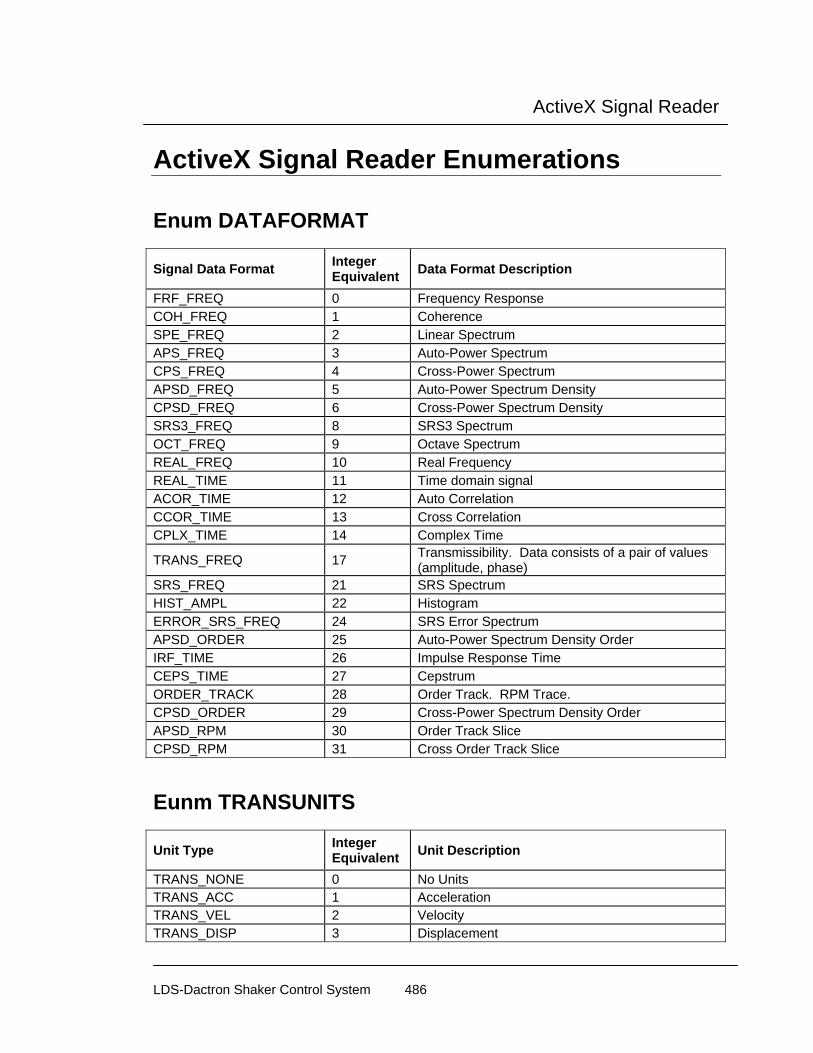
ActiveX Signal Reader
LDS-Dactron Shaker Control System 486
ActiveX Signal Reader Enumerations
Enum DATAFORMAT
Signal Data Format Integer Equivalent Data Format Description
FRF_FREQ 0 Frequency Response COH_FREQ 1 Coherence SPE_FREQ 2 Linear Spectrum APS_FREQ 3 Auto-Power Spectrum CPS_FREQ 4 Cross-Power Spectrum APSD_FREQ 5 Auto-Power Spectrum Density CPSD_FREQ 6 Cross-Power Spectrum Density SRS3_FREQ 8 SRS3 Spectrum OCT_FREQ 9 Octave Spectrum REAL_FREQ 10 Real Frequency REAL_TIME 11 Time domain signal ACOR_TIME 12 Auto Correlation CCOR_TIME 13 Cross Correlation CPLX_TIME 14 Complex Time
TRANS_FREQ 17 Transmissibility. Data consists of a pair of values (amplitude, phase)
SRS_FREQ 21 SRS Spectrum HIST_AMPL 22 Histogram ERROR_SRS_FREQ 24 SRS Error Spectrum APSD_ORDER 25 Auto-Power Spectrum Density Order IRF_TIME 26 Impulse Response Time CEPS_TIME 27 Cepstrum ORDER_TRACK 28 Order Track. RPM Trace. CPSD_ORDER 29 Cross-Power Spectrum Density Order APSD_RPM 30 Order Track Slice CPSD_RPM 31 Cross Order Track Slice
Eunm TRANSUNITS
Unit Type Integer Equivalent Unit Description
TRANS_NONE 0 No Units TRANS_ACC 1 Acceleration TRANS_VEL 2 Velocity TRANS_DISP 3 Displacement

ActiveX Signal Reader
LDS-Dactron Shaker Control System 487
TRANS_FORCE 4 Force TRANS_PRESSURE 6 Pressure TRANS_VOLT 7 Volts TRANS_ACC_ANGULAR 8 Angular Acceleration TRANS_RPM 9 RPM TRANS_USER1 101 User Defined 1 TRANS_USER2 102 User Defined 2 TRANS_USER3 103 User Defined 3
Enum WNDTYPE
Window Type Integer Equivalent Window Type Description
WT_OFF 0 No window WT_BARTLET 1 Bartlett window WT_HANNING 2 Hanning window WT_HAMMING 3 Hamming window WT_WELCH 4 Welch window WT_TUKEY 5 Tukey window WT_BLACKMN 6 Blackman (common) window WT_MINSIDE 7 Blackman's (4th) Minimum Side Lobe window WT_MAXDECA 8 Blackman's (4th) Maximum Decay window WT_FLATTOP 9 Flat top window WT_KAISER 10 Kaiser-Bessel window WT_FORCE 11 Force-Exponential Window WT_TRIANGLE 12 Triangle Window WT_HALFSINE 13 Half Window WT_FLATTOP_301 14 Flat top window (P301) WT_FLATTOP_310 15 Flat top window (p310) WT_FLATTOP_BK 16 Flat top window (B&K) WT_FLATTOP_HP 17 Flat top window (HP)
Enum WEIGHTING
Window Type Integer Equivalent Window Type Description
WEIGHTING_LINEAR 0 Linear Weighting WEIGHTING_A 1 A Weighting WEIGHTING_B 2 B Weighting WEIGHTING_C 3 C Weighting WEIGHTING_D 4 D Weighting WEIGHTING_NONE 5 No Weighting

ActiveX Signal Reader
LDS-Dactron Shaker Control System 488
Adding ActiveX Signal Reader to a Project This section will guide you through the process of adding the LDS-Dactron ActiveX Signal Reader to your project. The ActiveX Signal Reader should already be installed on your development PC. If it has not been installed, please install before continuing with this section.
Visual C++
Step 1- Create a dialog based application
• Start Visual C++ • Select “New” from the file menu
• Click on the Projects tab • Click “MFCAppWizard(EXE)” • Enter a name for the project (ReaderDemo)

ActiveX Signal Reader
LDS-Dactron Shaker Control System 489
• Click “Ok” • Select Dialog based as the type of application.
• Click “Finish” • Click “Ok” The default dialog based application is now configured.

ActiveX Signal Reader
LDS-Dactron Shaker Control System 490
Step 2 – Modify the User Interface
• Remove the “Cancel” button and rename the “Ok” button to “Exit”
• Add a new button and name it “Load Signal”
• Use the Class Wizard to add a message handler for the “Load Signal” button called “OnLoadsignal”
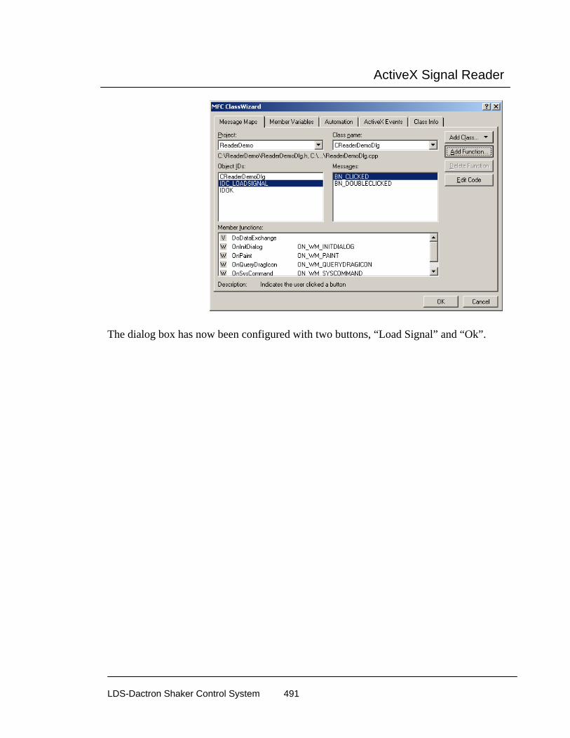
ActiveX Signal Reader
LDS-Dactron Shaker Control System 491
The dialog box has now been configured with two buttons, “Load Signal” and “Ok”.

ActiveX Signal Reader
LDS-Dactron Shaker Control System 492
Step 3 – Add the IDacSignal, IAdvancedSignal, and IChanStatus client interface classes
• Open the Class Wizard • Click the “Add Class” button and select “From Type Library”
• Locate and select your LDS-Dactron Signal Dll.
• Click “Open”

ActiveX Signal Reader
LDS-Dactron Shaker Control System 493
• Click “Ok“ to confirm the creation of the new classes.
The wizard will create classes for the IDacSignal, IAdvancedSignal, and IChanStatus interfaces.

ActiveX Signal Reader
LDS-Dactron Shaker Control System 494
Step 4 – Using the ActiveX Signal Reader in the project
• Include the LDS-Dactron Signal header in the ReaderDemoDlg.h file and add an IDacSignal member variable to the CReaderDemoDlg class. #include "LDS-DactronSignal.h" … IDacSignal m_LDS-DactronSignal; ...
• Add the following lines to CReaderDemoDlg::OnInitDialog() to initialize the COM library and to create an instance of the DacSignal.
CoInitialize(NULL); m_LDS-DactronSignal.CreateDispatch("LDS-DactronSignal.DacSignal.1");
• Add the following code to the OnLoadsignal() message handler to load a LDS-Dactron Signal named “demo.sig” when the “Load Signal” button is clicked. BOOL bSucceded; bSucceded = m_LDS-DactronSignal.LoadSignal("C:\\ReaderDemo\\demo.sig"); if(bSucceded) MessageBox("Signal loaded",MB_OK); else MessageBox("Error loading signal",MB_OK);
Step 5 – Test
Compile and run the application. When the “Load Signal” button is pressed, the signal in the demo.sig file will be loaded.

ActiveX Signal Reader
LDS-Dactron Shaker Control System 495
Visual Basic
Step 1 – Create a new project
• Start Microsoft Visual Basic • Select “New Project” from the “File” menu • Select “Standard EXE”
Step 2 - Add a reference to the LDS-Dactron ActiveX Signal Reader
• Select “References…” from the “Project” menu. • Locate and select the LDS-DactronSignal Type Library.

ActiveX Signal Reader
LDS-Dactron Shaker Control System 496
• Click “Ok”
Step 3 – Modify the User Interface
• Add two buttons to the form, one to load the signal and the other to quit the application.
Step 4 – Add functionality to the User Interface
• Add a LDS-Dactron Signal to the default form Private LDS-DactronSignal As New DacSignal
• Add the following code the Load Signal Click event handler. Dim bSucceded As Boolean bSucceded = LDS-DactronSignal.LoadSignal("demo.sig") If (bSucceded) Then
MsgBox ("Signal loaded") Else
MsgBox ("Error loading Signal") End If
Step 5 – Test
Run application. When the “Load Signal” button is pressed, the signal in the demo.sig file will be loaded.

Shaker Vibration Control Theory
LDS-Dactron Shaker Control System 497
10 Shaker Vibration Control Theory
Overview This chapter discusses the basic algorithms, control theory, and digital signal processing technology used in LDS-Dactron’s Shaker Control System.
A vibration test is defined in terms of an excitation level to be applied to the Unit Under Test (UUT). To perform this type of test, the control system must drive the shaker and monitor the excitation level actually produced. If the control signal indicates that shaker output is other than desired, adjustments are made to the drive signal so that the output of the shaker will converge with the test profile. The control system continuously, in real-time, corrects for the dynamics of the shaker/UUT load to maintain accurate control. Safety checking is enhanced by a distributed processing architecture that handles the control loop independent of the PC host computer.
The block diagram shows the process closed-loop random vibration control. Sensors such as accelerometers are used to measure the response of the UUT (these sensors provide the Control Signal). The purpose of a random controller is to continuously output a signal (Drive Signal) so that the power spectral density of the control signal (Measured Signal) has the defined spectrum shape. This defined spectrum shape is called the Reference Spectrum.
Shaker
Unit Under Test (UUT)
Amplifier
RandomVibrationController
control signal
drive signal t
f
tReference Spectrum
Random Vibration Controller Block Diagram
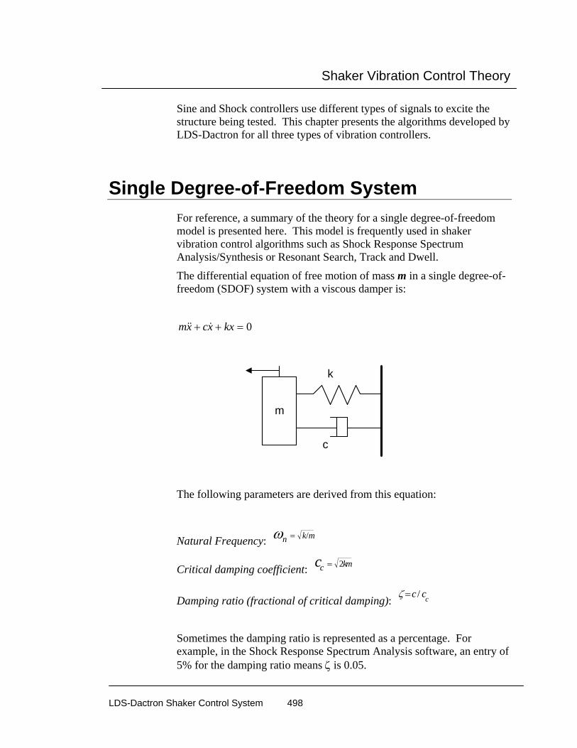
Shaker Vibration Control Theory
LDS-Dactron Shaker Control System 498
Sine and Shock controllers use different types of signals to excite the structure being tested. This chapter presents the algorithms developed by LDS-Dactron for all three types of vibration controllers.
Single Degree-of-Freedom System For reference, a summary of the theory for a single degree-of-freedom model is presented here. This model is frequently used in shaker vibration control algorithms such as Shock Response Spectrum Analysis/Synthesis or Resonant Search, Track and Dwell.
The differential equation of free motion of mass m in a single degree-of-freedom (SDOF) system with a viscous damper is:
mx cx kx&& &+ + = 0
m
k
c
The following parameters are derived from this equation:
Natural Frequency: ωn k m= /
Critical damping coefficient: cc km= 2
Damping ratio (fractional of critical damping): ζ =c cc/
Sometimes the damping ratio is represented as a percentage. For example, in the Shock Response Spectrum Analysis software, an entry of 5% for the damping ratio means ζ is 0.05.

Shaker Vibration Control Theory
LDS-Dactron Shaker Control System 499
Resonance Frequencies: The peak of the displacement, velocity, and acceleration response of a system undergoing forced, steady-state vibration occur at slightly different forcing frequencies. A resonance frequency is defined as the frequency for which the response is a maximum.
Displacement resonance frequency: ω ζn ( ) /1 2 2 1 2−
Velocity resonance frequency: ω n
Acceleration resonance frequency: ω ζn ( ) /1 2 2 1 2−
For physical systems with small damping ratios, say ζ<0.1, the difference among the three resonance frequencies is negligible.
Quality Factor Q: Q = 1/(2ζ)
Bandwith at Half-Power Point ∆ω: ∆ω = ω n /Q = 2ζω n
Random Vibration Control
Random Control Process Random excitation is often used to simulate real world vibration. The purpose of the random vibration control system is to generate a true random drive signal such that, when the signal is applied via an amplifier/shaker to the device under test, the resulting shaker output spectrum will match a user-specified reference spectrum. The reference profile is defined in the frequency domain in units of (Acceleration)2/Hz. This signal is to be applied to the UUT for a specified amount of time to verify the device's ability to function in its service environment.
If the series of components being controlled (i.e., the amplifier, shaker, and testing structure) is assumed to be an integrated linear system, then it can be described by a system transfer function H(f) in frequency domain. The frequency spectra of the control and drive signals, Y(f) and X(f), can be linked together by H(f) as:

Shaker Vibration Control Theory
LDS-Dactron Shaker Control System 500
Y(f) = H(f) X(f) (1)
Or
X(f) = H(f) -1 Y(f) (2)
Where H(f) -1 is called the inverse transfer function.
If a flat spectrum drive signal excites a shaker/test-article system, the resulting acceleration response spectrum will not be flat. The armature resonances and the dynamics of the test-article react on the system to produce peaks (resonances) and valleys (anti-resonances) in the resultant spectrum.
To apply a specified spectrum to the test article, the drive spectrum must be altered to correct for the dynamics of the shaker/load combination. This process is generally referred to as “Equalization”. The inverse transfer function is calculated while the test is ongoing to monitor any change in the system transfer character. Corrections are applied in real-time.
Given a desired spectrum R(f) (reference spectrum, or profile), the required value for the drive can be calculated as:
X(f) = H(f) -1 R(f) (3)
Where X(f) is the spectrum of the required drive signal.
Once the drive spectrum X(f) is known, there are several ways to generate a random output signal in the time domain. The following constraints are used when generating the output signal x(t):
• It has the spectral shape defined by X(f).
• It is a continuous waveform (without any gap, periodic structure, or discontinuity (no glitches).
• It has a Gaussian or (clipped by N-sigma) amplitude distribution.

Shaker Vibration Control Theory
LDS-Dactron Shaker Control System 501
The algorithm can be summarized with the following procedures:
Step 1. Digitize the input signals and transform them into frequency domain using the FFT process.
Step 2. Estimate the inverse system transfer function between the averaged input and output via cross-spectral method.
Step 3. Generate a reference spectrum with random phase.
Step 4. Multiply the reference spectrum by the inverse transfer function, and apply an Inverse FFT to the result to generate the output-time waveform.
Step 5. Output the time waveform through a D/A converter.
All these calculations are completed within one frame-period to ensure a very fast control loop time.
y1(f)
Control PSD
FFT
Auto PowerSpectrum
Average
Output
x(f)
DrivePSD
FFT
Cross PSD
Compute InverseTransfer Function
H-1
Multiply
PhaseRandomizer
IFFT
window
Safety Limit Checking
ReferenceEditor
R(f)
y1(t)
y2(f)
FFT
window
y2(t)
channel averaging
x(t)
window
8 channel inputs (control signals)
one channel output (drive signal)
Cross PowerSpectrum
Auto PowerSpectrum
Average Average
LDS-Dactron Controller Functional Block Diagram
Shaker Vibration Control Theory
LDS-Dactron Shaker Control System 502
During the control process various safety checks are applied to ensure that (1) the test is being performed as defined, (2) the shaker feedback can be measured, and (3) the drive signal is not clipped.
Safety Checks
High-line Abort / Low-line Abort
Line checking is done by comparing the control signal and the abort tolerances on a per-spectrum-line basis. If the control signal is higher or lower than the abort limits by a specified percentage, the system will abort the test. Because the shape of abort tolerances is defined by the user, this safety check can tailor UUT protection based on particular frequency bands.
High-RMS Abort / Low-RMS Abort
The RMS check compares the overall RMS value of the control signal to user-defined limits. This check protects the UUT from an overall energy standpoint.
Control Signal Loss
This feature protects against over test by detecting the loss of the control signal. In the event of a control signal loss, the system quickly and smoothly shuts the Drive signal down
Maximum Output Voltage Check
This function protects the shaker amplifier from an input voltage overload.
Mixed-mode Control Mixed-mode is a general term for the following advanced vibration control packages:
• Sine-on-Random

Shaker Vibration Control Theory
LDS-Dactron Shaker Control System 503
• Random-on-Random
• Sine-and-Random-on-Random
The majority of vibration experienced by equipment in service can be characterized by broadband random. In some cases, the vibration is more appropriately characterized by periodic or pseudo-periodic excitation together with low-level broadband random. Example cases include excitation from gunfire and reciprocating machinery or helicopter rotors. The Mixed-mode simulates these complex vibration environments.
LDS-Dactron’s mixed-mode control system uses broadband random, multiple swept narrowband random, and multiple swept sine waves simultaneously.
The control algorithm can be divided into three parts: a broadband random control loop, a multiple-narrowband random spectrum generator, and a multiple-sine control loop as shown in the diagram below.
shaker
broadbandrandom control
loop
narrowbandrandom control
loop
multiple sinecontrol loop
sum
burstcontrol
control signal
drive signal
Mixed-mode Control
The broadband random control part of the control algorithm uses the same methods as the random only control algorithm. In both cases, the profile is defined in the PSD domain.

Shaker Vibration Control Theory
LDS-Dactron Shaker Control System 504
The multiple narrowband random signals are generated by a continuous modification to a separate random reference spectrum (the narrowband profile). A similar technique has been described in reference [5]. Each narrow-band random signal has its own profile (amplitude target) and pre-defined sweep speed and sweep range. After the narrowband signals are generated, they are added into the broadband portion. The internal control loop of the narrowband portion is faster than broadband control to ensure smooth sweeping. Random-on-Random places much heavier demand on computational resources than the basic broadband random controller.
LDS-Dactron’s multiple sine tone control technique is proprietary. A tracking filter with proportional bandwidth extracts each sine tone. The tracking filter is applied to the drive signal and all the measured input signals.
In the case of Sine-and-Random-on-Random, The LDS-Dactron shaker control system can control up to 12 sine tones. There are 12 independent Sine controllers working in parallel with two other random controllers (one for broadband and one for narrowband).
When the narrowbands are turned on or off, there is a smooth, gradual level decay or rise in the narrowband frequency bands. Ramp-up and ramp-down rates for the narrowbands are settable.
There are two modes to turn narrowbands on or off: automatic or manual. With the “automatic” mode, they can be controlled through the schedule. Manual operation allows you to turn them on or off at any time.
In simulating gunfire, the sine tones must be turned on/off in milliseconds, not seconds. This can be done using a Burst-Mode feature. The on-time and the off-time for the tones are settable.

Shaker Vibration Control Theory
LDS-Dactron Shaker Control System 505
time-on time-off
turned-on manually orby schedule
turned-off manually orby schedule
Controlled by theBurst-Mode setup
time
Each of the 12 tones can have its own sweep speed, and sweep range. Mil-Std-810E requires a harmonic-tone test mode. When this mode is enabled, all of the narrowbands sweep synchronously in a harmonically related manner. The first narrowband signal is defined as the “fundamental” sweeping component; the remaining narrowbands are considered harmonics of the fundamental.
Swept Sine Vibration Control Swept-Sine is another common vibration test. As the name implies, the drive signal to the shaker is a sine wave that changes in a smooth continuous manner over a range of frequencies. The amplitude level of the reference profile can be defined in acceleration, velocity or displacement units.
A swept-sine test specification includes the following:
• The upper and lower frequency limits of the test.
• The level to be maintained at the appropriate frequency.
• The rate at which the frequency will sweep (logarithm or linear).
• The duration of the test or the number of sweeps.

Shaker Vibration Control Theory
LDS-Dactron Shaker Control System 506
A high-precision digital sine wave generator is required for the sine vibration control system. The drive signal (time domain) output is calculated based on:
( )d An n n= sin θ (4)
Where: θ n is the phase at nth sample
An is the amplitude at nth sample
dn is the drive signal output amplitude at nth sample
An , f n are provided by control logic. The generator uses f n to compute
phaseθ n , then provides dn for output.
In this control system, a look-up table of pre-calculated values is used instead of directly calculating the sine function in real time. One sine wave cycle (from 0 to 2π) with M samples is pre-calculated and stored in memory. The sine look-up table can be accessed by a base pointer (points to sine(0.0)) and an index pointer (<M). The phase can be scaled to the range of (0, M).
∆
∆
θ π
θθ
θπ
=
= =
2
2
M
Index Mnn n
(5)
Then
d pSineTable Indexn n= +*( ) (6)
Reference [1] studied the SNR (Signal-Noise-Ratio) and the computational requirements of various methods for generating sine waves: Polynomial Expansion, Direct Table Look-up and Table Look-up

Shaker Vibration Control Theory
LDS-Dactron Shaker Control System 507
with Linear Interpolation. It concluded that the Table Look-Up with Interpolation is the most appropriate method for applications such as sine vibration controllers.
The output frequency can be held at a fixed frequency, stepped in a sequence of fixed frequencies, or swept in time over a range of frequencies. Swept-sine changes the frequency in a smooth continuous manner. The rate of frequency change is called the sweep rate. Both log and linear swept rates are provided. The operating range of this control system extends from 0.5 Hz to 10 kHz.
Sine Control Process The control system generates an output sine wave to excite the device under test. A level detector measures the control signal amplitude. The control signal amplitude is then compared with the reference amplitude and the Drive signal amplitude is updated.
Comparator
Control (measured fromtest species)Reference
Drive (output to theshaker amplifier)
ω
Updating the Drive Signal by Comparing the Control with the Reference
The level detector outputs results based on one of the following measurement processes:
• Tracking filter
• RMS
• Peak
• Mean

Shaker Vibration Control Theory
LDS-Dactron Shaker Control System 508
The Tracking Filter detector produces amplitude and phase data, while the other measurement methods only produce amplitude data.
The Channel Average block is used to combine the results of multiple channel detectors and then generate the single control signal.
...
Chn 1Detector
Chn 2Detector
Chn 3Detector
ChannelAveraging
BlockControl (A, ω )
AveragingLogicExp.
Averaging
Exp.Averaging
Exp.Averaging
Multiple Channel Averaging
Real-time Tracking Filter with Adaptive Bandwidth Tracking filters greatly reduce the noise and harmonic signals above and below the sine drive frequency. A tracking filter has two major characteristics that specifically address Sine Control for shaker systems. First, the tracking filter has a center frequency that is always tuned to the current drive frequency. This allows all other signals to be rejected from measurement and control. Second, the bandwidth can be defined as either a fixed frequency span or a span that changes as a function of the operating frequency.
Some shaker control systems [3] use a linear average over a changing period of time to achieve the effect of a tracking filter. This type of filter can only provide about –13 dB rejection at the stop band because the “filter” has essentially a rectangular data window.

Shaker Vibration Control Theory
LDS-Dactron Shaker Control System 509
f2f1 frequency
A tracking filter with changing bandwidth and center frequencycan eliminate the noise outside the band
Tracking Filter Shapes
The System’s DSP computational power allows the use of a unique algorithm to realize an extremely high-performance tracking filter. This algorithm is described below:
Step 1. Based on the current drive frequency and filter type (fixed or proportional bandwidth), the DSP calculates the current tracking filter bandwidth and the center frequency of the filter.
Step 2. The DSP calculates updated band pass filter coefficients adaptively in real-time.
Step 3. It applies the filter to the data of each input channel.
f1 frequency
Sweeping Frequency
Filter bandwidth type (fixedor proportional)
calcu-lationFilter coefficients
Tracking Filter Construction
The tracking filter is calculated “on-the-fly” based on the current operating frequency and bandwidth requirement. This operation is re-executed every few milliseconds. The filter generated through this

Shaker Vibration Control Theory
LDS-Dactron Shaker Control System 510
approach has a rejection of about –60 dB at the stop band. The output of the filter goes through the averager to produce one control amplitude value. This value is then used by the comparator to correct the drive amplitude. This process results in exceptionally accurate control.
RMS, Mean, and Peak Detection The Peak, Mean, and RMS level detectors analyze time domain data over preset historical durations. This duration can be computed based upon the selected bandwidth as follows:
History duration (second) = 1/bandwidth (Hz)
Both fixed and proportional bandwidths are supported. Fixed bandwidths imply a constant historical analysis duration over the entire test. Proportional bandwidths imply a changing historical analysis duration as the test progresses.
For example, if a fixed bandwidth of 100 Hz has been selected, the historical analysis duration would be 0.01 seconds.
History duration
RMS Detector
Peak Detector
DC Detector
Events during Historical Duration
Assume N is the history duration calculated, according to the selected bandwidth. The RMS is computed by:

Shaker Vibration Control Theory
LDS-Dactron Shaker Control System 511
RMSN
x ii
N
==
−
∑1 2
0
1
( )
The Mean is computed by:
MeanN
ABS x ii
N
==
−
∑10
1
( ( ))
And, the Peak is computed by:
Peak = (+ Peak) + | (- Peak) |
2
The RMS, Mean and Peak measurements do not provide a linear relationship in the frequency domain. Signals at harmonics of the drive frequency can contribute to the final overall measurement result. Therefore, the drive level may be lower than if a tracking filter processing is used.
On the other hand, a tracking filter measures only signals within the filter band around the drive frequency. Hence, a higher excitation level will result as the harmonic responses are filtered out.
Resonant Search, Dwell and Track (RSTD) This section covers the basics of the resonance search and tracked dwell process used in LDS-Dactron’s Shaker Control System.
RSTD Requires Transmissibility Measurement The following explanations are drawn from the Shock and Vibration Handbook (by Cyril Harris) :
The peak of the displacement, velocity, and acceleration response of a system undergoing forced, steady-state vibration occur at slightly

Shaker Vibration Control Theory
LDS-Dactron Shaker Control System 512
different forcing frequencies. A resonance frequency is defined as the frequency for which the response is a maximum.
There are three types of resonance frequency
Displacement resonance frequency: ω ζn ( ) /1 2 2 1 2−
Velocity resonance frequency: ω n
Acceleration resonance frequency: ω ζn ( ) /1 2 2 1 2−
For physical systems with small damping ratios, say ζ<0.1, the difference among the three resonance frequencies is negligible.
A direct method to find resonances is to measure the transfer function between the response signal of the test article (acceleration, velocity or displacement), and the force excitation signal. The resonance will be the peak on the transfer function curve. Unfortunately, this approach is unpractical in the shaker control operation because the force measurement is not easy to obtain. Instead, the transmissibility measurement is commonly used to find the resonance.
Two accelerometers (one on the shaker table, the other on the UUT) are used to measure acceleration transmissibility between these two points. These signals are sampled simutaneously. The transmissibility function is computed based on the ratio of the two acceleration signals.
Shaker
Test Unit
reference channel
response channel
Test Setup Every input channel needs a Tracking Filter enabled to measure the phase relationship between the response and reference channels of the transmissibility function.

Shaker Vibration Control Theory
LDS-Dactron Shaker Control System 513
It is critical to select the right mount locations for the accelerometers used for the reference and response channels. The wrong location may make it impossible to find the resonance. Even worse, if the response and reference channels are reversed, anti-resonances will appear as resonances. The figure below illustrates this point. The two plot traces, transmissibility 2,1(f) and transmissibility 1,2(f), are measurements taken on the same structure, but with the response/reference definition reversed.
transmissibility1,2(f) transmissibility2,1(f)
700.0015.000 100.00
50.000
-45.000-40.000
-30.000
-20.000
-10.000
0
10.000
20.000
30.000
40.000
Frequency (Hz)
dB
Comparison of Two Transmissibility Functions
The signals displayed above are measured on a beam excited by an electrodynamic shaker. A dozen resonant frequencies are shown in the graph. The vibration controller allows the user to select certain parameters such as Q (Quality Factor) or Amplitude Ratio Threshold as the criteria for detecting these resonant frequencies. After the controller finds the resonant frequencies in the sweep range, the user has the opportunity to manually edit the resulting dwell frequency list.
The accelerometer of the reference channel should be mounted on the shaker table in a location that will accurately record the base movement. The accelerometer of the response channel should be mounted on the test article in the location that has the most obvious resonance vibration. The user should avoid selecting a node as the response point.
If there is more than one response channel in use, run a low-level test and observe the resonance of each transmissibility function. Select a function with a clean, high-amplitude peak to use for resonance searches.

Shaker Vibration Control Theory
LDS-Dactron Shaker Control System 514
In the LDS-Dactron control system, the transmissibility function is represented as:
Transmissibility y,x (f) = channel y / channel x
where y is the response channel and x is the number of the reference channel.
After the resonance search, the frequencies detected are used in testing the article. There are two types of tests in this application: Frequency-Locked Dwell or Resonance-Tracked Dwell.
Frequency-Locked Dwell Frequency-Locked Dwell means the controller will output a frequency fixed at a point selected in the search process. The dwell will continue until one or more pre-defined conditions are met. For example, during fatigue testing, the resonant frequency may shift so the ratio of transmissibility at the dwell frequency may decrease. The amount of this decrease can be set as a condition that terminates the dwell event.
Transmissibility Transmissibility
resonant frequency shifted
f0f0
Frequency-Locked Dwell
Resonance-Tracked Dwell Resonance-Tracked dwell is used in applications such as fatigue testing. The controller monitors the resonance frequency and adjusts the drive frequency as the resonance frequency changes. This change may be

Shaker Vibration Control Theory
LDS-Dactron Shaker Control System 515
caused by environmental conditions or changes in the mechanical properties of the UUT caused by progressive damage. The resonant condition is maintained throughout the test until certain criteria are met.
Transmissibility Transmissibility
resonant frequency shifted while theexcitation frequency keeps tracking
f0f0 f1
Resonance-Tracked Dwell (Automatic Frequency Adjustment)
Theoretically, resonance tracking can be implemented based on the fact that the phase of the transmissibility between response and excitation force is out of phase by 90°. However, this approach is impractical because it is almost impossible to measure the excitation force. Some methods use the drive signal to represent the excitation force. This is not a correct representation of the force applied. In addition, the phase will not be 90° if the mechanical system has more than one vibration mode.
The phase of the transmissibility function between the response and the reference channels is computed and used as a tool for resonance tracking.
transmissibility2,1(f)
700.0015.000 100.00
200.00
-200.00-180.00
-150.00
-120.00
-90.000
-60.000
-30.000
0
30.000
60.000
90.000
120.00
150.00
180.00
Frequency (Hz)
Degree
Phase Plot of a Typical Transmissibility Function

Shaker Vibration Control Theory
LDS-Dactron Shaker Control System 516
The control algorithm tracks the resonance by monitoring the transmissibility function’s phase value. If the resonance frequency drifts, the phase change indicates the direction of the resonance’s frequency shift.
Classical Shock Control The Classical Shock Control package reproduces waveforms such as halfsine, sawtooth or trapezoid shapes on the shaker. The control system will reproduce the time domain of the selected waveform at the defined acceleration level and duration.
In Shock, two operations are involved:
• Generation of the profile waveform
• Equalization and control
The LDS-Dactron Control System includes seven types of classical waveforms:
• Halfsine
• Haversine
• Terminal Peak Sawtooth
• Initial Peak Sawtooth
• Triangular
• Rectangular
• Trapezoid

Shaker Vibration Control Theory
LDS-Dactron Shaker Control System 517
Half-Sine Classical Shock Pulse
Waveform Compensation At the end of a shock test, the shaker table must be “at rest.” Waveform compensation ensures that the velocity and displacement will be zero at the end of the test.
A pulse with a classical acceleration waveform will produce non-zero ending velocity and displacement. To reproduce the pulse on a shaker, the ending velocity and displacement must be zero (or close to zero). Therefore the drive signal must be conditioned so that the initial and ending acceleration, velocity, and displacement values are zero. This is done by adding compensation waveforms before and after the main pulse.
Acceleration
Velocity
Displacement
time
time
time
Acceleration, Velocity, and Displacement of an Uncompensated Shock Pulse

Shaker Vibration Control Theory
LDS-Dactron Shaker Control System 518
Given the parameters of the classical shock waveform, the corresponding optimized waveform can then be calculated. Many types of optimization methods are available, including:
• Pre-pulse only, with half-sine compensation
• Post-pulse only, with half-sine compensation
• Pre-pulse and post-pulse, with half-sine compensation
• Pre-pulse only, with rectangular compensation
• Post-pulse only, with rectangular compensation
• Pre-pulse and post-pulse, with rectangular compensation
• Pre-pulse and post-pulse, with double rectangular compensation
• Pre-pulse and post-pulse, with triangle compensation
• Minimum displacement
• Minimum duration
The waveforms are all defined in terms of acceleration in the time domain. The expression for half-sine is
a t A t
T( ) sin( )= ×
⋅π
(9)
Post-test velocity can be removed by adding a long-duration bias pulse with a velocity change equal and opposite to the velocity change of the selected classical waveform. By timing the delay properly between the start of the velocity-compensation pulse and the desired waveform, it is usually possible to produce the desired event within the displacement limits of the shaker.
Shock Pulse Compensation
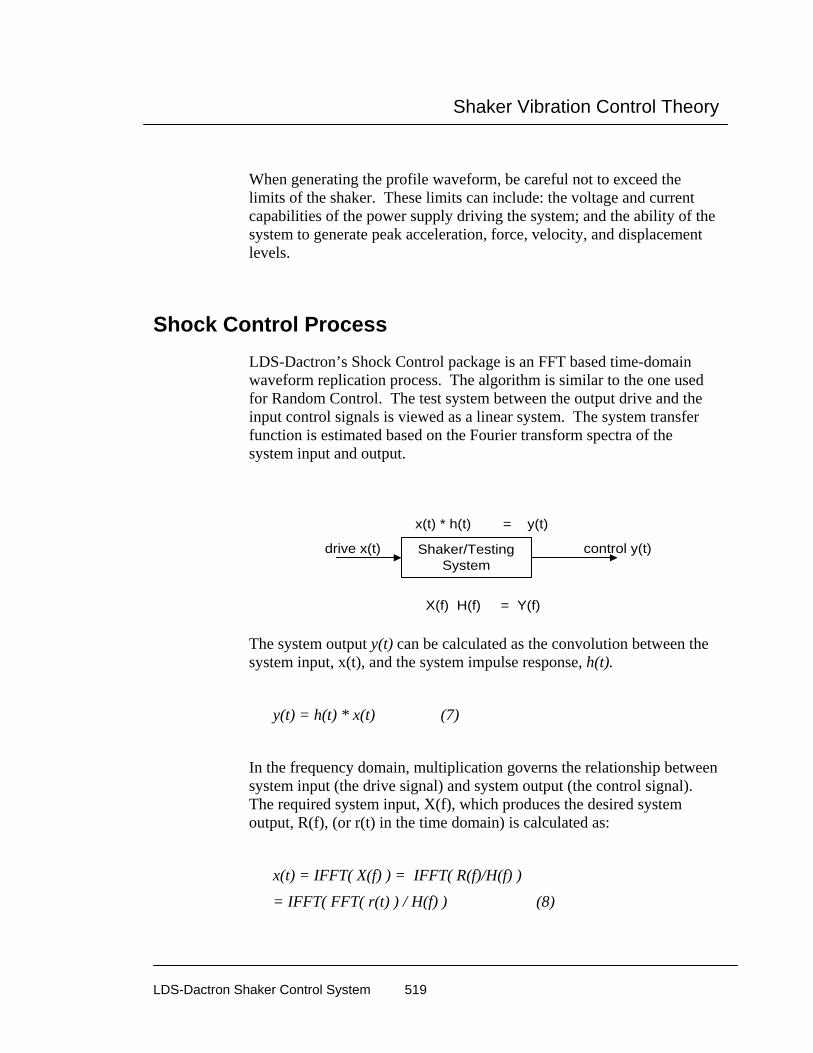
Shaker Vibration Control Theory
LDS-Dactron Shaker Control System 519
When generating the profile waveform, be careful not to exceed the limits of the shaker. These limits can include: the voltage and current capabilities of the power supply driving the system; and the ability of the system to generate peak acceleration, force, velocity, and displacement levels.
Shock Control Process LDS-Dactron’s Shock Control package is an FFT based time-domain waveform replication process. The algorithm is similar to the one used for Random Control. The test system between the output drive and the input control signals is viewed as a linear system. The system transfer function is estimated based on the Fourier transform spectra of the system input and output.
Shaker/TestingSystem
x(t) * h(t) = y(t)
drive x(t) control y(t)
X(f) H(f) = Y(f)
The system output y(t) can be calculated as the convolution between the system input, x(t), and the system impulse response, h(t).
y(t) = h(t) * x(t) (7)
In the frequency domain, multiplication governs the relationship between system input (the drive signal) and system output (the control signal). The required system input, X(f), which produces the desired system output, R(f), (or r(t) in the time domain) is calculated as:
x(t) = IFFT( X(f) ) = IFFT( R(f)/H(f) )
= IFFT( FFT( r(t) ) / H(f) ) (8)
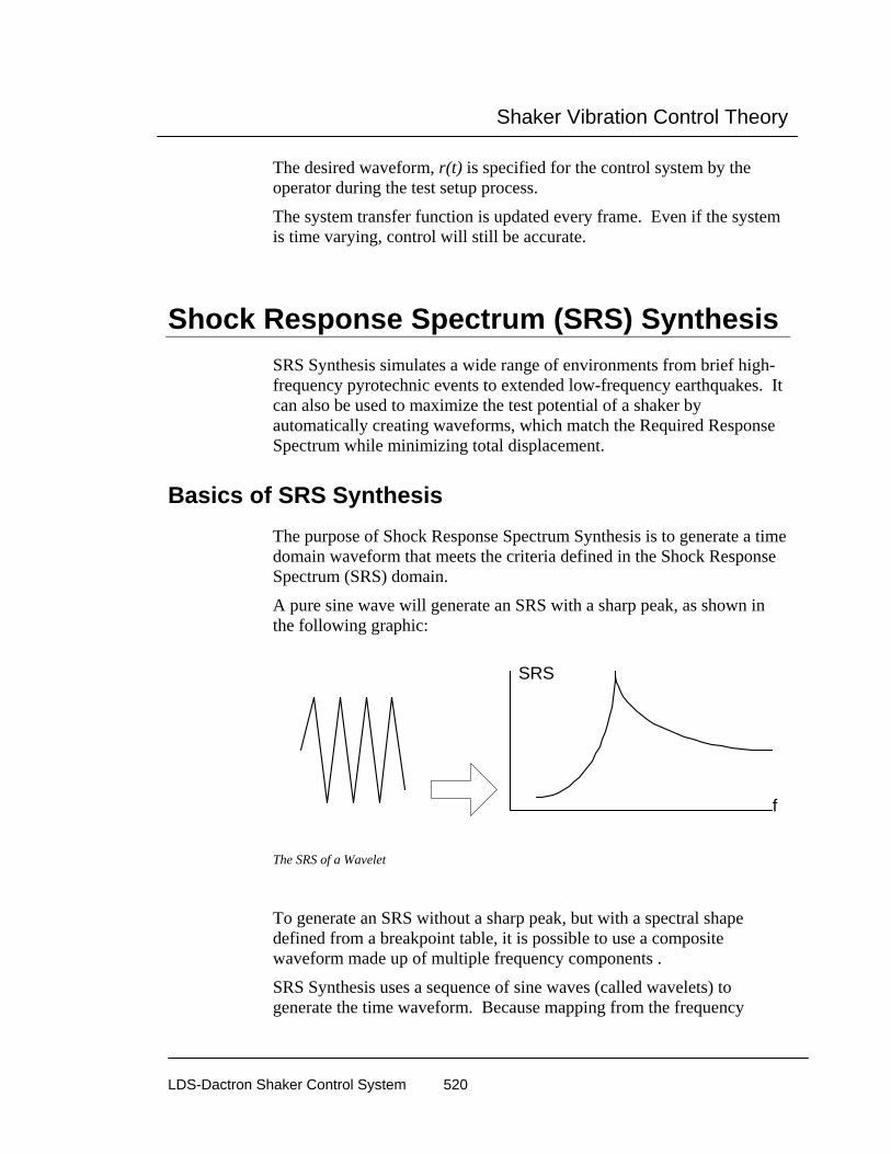
Shaker Vibration Control Theory
LDS-Dactron Shaker Control System 520
The desired waveform, r(t) is specified for the control system by the operator during the test setup process.
The system transfer function is updated every frame. Even if the system is time varying, control will still be accurate.
Shock Response Spectrum (SRS) Synthesis SRS Synthesis simulates a wide range of environments from brief high-frequency pyrotechnic events to extended low-frequency earthquakes. It can also be used to maximize the test potential of a shaker by automatically creating waveforms, which match the Required Response Spectrum while minimizing total displacement.
Basics of SRS Synthesis The purpose of Shock Response Spectrum Synthesis is to generate a time domain waveform that meets the criteria defined in the Shock Response Spectrum (SRS) domain.
A pure sine wave will generate an SRS with a sharp peak, as shown in the following graphic:
f
SRS
The SRS of a Wavelet
To generate an SRS without a sharp peak, but with a spectral shape defined from a breakpoint table, it is possible to use a composite waveform made up of multiple frequency components .
SRS Synthesis uses a sequence of sine waves (called wavelets) to generate the time waveform. Because mapping from the frequency

Shaker Vibration Control Theory
LDS-Dactron Shaker Control System 521
domain to time domain is not linear, the synthesis may not converge. The synthesis process may also require iteration.
“Shaped” sine waves are used for waveform synthesis. Shaping methods include windows such as an Exponential Tapering and Hanning.
f
SRS
The SRS of Multiple Wavelets
If we have a collection of wavelets that contain different frequencies, the combination of these wavelets will give a “controllable SRS”. By changing the amplitudes of these wavelets, the shape of this SRS can be controlled to an extent. This is the basic mechanism of SRS synthesis.
Although the synthesized waveform may meet the SRS criteria, it may not meet the zero ending-velocity and zero ending-displacement criteria. Therefore, after the waveform is synthesized, it still needs compensation in order to meet the zero-ending value criteria to use with a shaker table.
The synthesis process uses an iterative method called Analysis-Based-Synthesis. It can be described as follows:

Shaker Vibration Control Theory
LDS-Dactron Shaker Control System 522
User defines the waveform type. If sine wave, select followingwindow types: RECT, HANN, EXP, ...
User defines other criteria such as time duration, etc.
User defines the Required SRS including frequency range,resolution, damping etc. These parameters can be different fromthat of SRS Analysis. In the other words, users can analyze the
data with another set of SRS parameters.
System calculates the sampling rate and other parameters such asthe number of periods of sine waves.
Make the first guess of frequency/amplitude of the sine wavesthen start the following iteration
DO SRS Analysis
Compare the Required SRS and the SRS of the time waveformbeing synthesized. Adjust the amplitude (or the frequency, or the
length) of each individual sine waves.
If the Error is less than what user specified or the synthesis isdiverging, stop the synthesis. Otherwise do another iteration.
Waveform compensation (zero-vel and zero-disp)
The practical implementation of the algorithm is very complex. It is sometimes difficult to select the various parameters used in the synthesis. For a better understanding of the SRS Synthesis algorithm, see Reference [6].
The following examples illustrate the SRS Synthesis process.
The first figure below shows a time waveform with only one wavelet. The wavelet is a sine waveform with 51 half cycles and a sine data window. Its SRS is shown in the second figure.

Shaker Vibration Control Theory
LDS-Dactron Shaker Control System 523
profile(t)
682.5m0 100.0m 200.0m 300.0m 400.0m 500.0m 600.0m
720.0m
-720.0m-700.0m
-600.0m
-500.0m
-400.0m
-300.0m
-200.0m
-100.0m
0
100.0m
200.0m
300.0m
400.0m
500.0m
600.0m
Time (seconds)
G
Time Waveform with One Wavelet
control(f)
1.0K2.5 100.0
39.8
10.0m
100.0m
1.0
10.0
Frequency (Hz)
G
The SRS of Time Waveform with One Wavelet
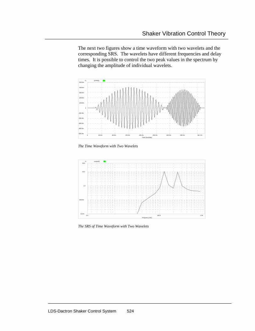
Shaker Vibration Control Theory
LDS-Dactron Shaker Control System 524
The next two figures show a time waveform with two wavelets and the corresponding SRS. The wavelets have different frequencies and delay times. It is possible to control the two peak values in the spectrum by changing the amplitude of individual wavelets.
profile(t)
341.2m0 40.0m 80.0m 120.0m 160.0m 200.0m 240.0m 280.0m
500.0m
-500.0m
-400.0m
-300.0m
-200.0m
-100.0m
0
100.0m
200.0m
300.0m
400.0m
Time (seconds)
G
The Time Waveform with Two Wavelets
control(f)
1.0K2.5 100.0
39.8
10.0m
100.0m
1.0
10.0
Frequency (Hz)
G
The SRS of Time Waveform with Two Wavelets

Shaker Vibration Control Theory
LDS-Dactron Shaker Control System 525
Combining many wavelets results in a pulse representative of the real world and a match to the SRS across the frequency range. The following two figures show a waveform synthesized with 24 wavelets at different frequencies and the corresponding SRS. Using many wavelets, a smooth SRS spectrum is obtained.
profile(t)
682.5m0 100.0m 200.0m 300.0m 400.0m 500.0m 600.0m
6.9
-5.9
-5.0
-4.0
-3.0
-2.0
-1.0
0
1.0
2.0
3.0
4.0
5.0
6.0
Time (seconds)
G
The Time Waveform with 24 Wavelets
profile(f) high-abort(f) low-abort(f) control(f)
1000.002.46 100.00
39.81
0.11
1.00
10.00
Frequency (Hz)
G
The SRS of the Time Waveform with 24 Wavelets

Shaker Vibration Control Theory
LDS-Dactron Shaker Control System 526
Limiting Control with Automatic Drive Notching
Limiting control is a software option for the following software packages:
• Swept-Sine Control,
• Random Control, and
• All Mixed-mode Control (SoR, RoR, SRoR).
Any of the enabled input channels can be used as a limiting channel. Limiting control can be applied to any channel selected as either a Control channel or Monitor channel.
PSDWeightedAverage
MainControlLoop
LimitingControl
LimitingControl
drive spectrum
input 1
input 2
input 3
drive
control(f)
Limiting Control Block Diagram
In Random, limiting control is applied to the drive signal’s PSD. The control(f) signal, which is generated either from the weighted average of multiple channels, or from a single measurement, is used in the main control loop to generate the drive spectrum. Each limit control block may modify the drive spectrum further, based on the comparison between the limiting profile and the input spectrum. As a result, the generated drive may contain less energy in particular frequency ranges. This process is also called “Automatic Drive Notching.”

Shaker Vibration Control Theory
LDS-Dactron Shaker Control System 527
Sine limiting control is similar to Random except that it requires even faster computation (shorter loop time).
The limiting control for SoR uses similar technology with a more complicated structure. In addition to the 8 random limiting control blocks, each sine tone needs one separate limiting control block. In the extreme case of 8 input channels, 12 sine tones are enabled at the same time. This requires a total of 8 + 8 x 12 = 104 limiting control blocks.
Long Time History Replication Long Time History (LTH) is used to replicate recorded time domain waveforms such test track data for automobiles and seismic events. The other vibration control applications such as Random, Sine and Shock use a modeled approach to simulate vibration environments. For example, in Sine the controller outputs a precise sine wave with a specified frequency, amplitude, and sweep rate. A mathematical model, the amplitude versus frequency spectrum, describes the excitation signal supplied to the shaker. Similarly, in Random the controller follows a frequency domain profile to generate the drive signal. Classical Shock requires a control signal with a time domain shape derived from as mathematical model such as a half-sine function.
The drawback of these modeled approaches is that the real environment can never be precisely simulated. For example, consider the vibration an automobile experiences as it is driven over a rough road surface. Although the vibration waveforms tend to appear as random-like signals, they are actually a combination of random waveforms, shock transients, and cyclic signals. Instead of using a mathematical model to generate a drive signal, LTH duplicates a waveform recorded in a field test.
Real-time LTH Time Domain Control There are several approaches for time domain control. One way is by using a drive signal calculated off-line. This approach first measures the system transfer function (Hsys). An iterative process computes the drive signal, segment by segment, based on the waveform profile and measured Hsys. Then whole drive signal is saved to a disk file. During the test, the drive signal is simply re-played. This approach has a number of disadvantages:

Shaker Vibration Control Theory
LDS-Dactron Shaker Control System 528
1. It is very time-consuming to develop the drive signal because of the iterative segment-by-segment processing method used.
2. During the test, the control system can not adjust for changes in the shaker or test-article dynamic response. This method is essentially an open-loop control technique.
LDS-Dactron’s LTH control application uses a real-time closed-loop control algorithm. LTH’s algorithm continuously computes the drive signal based on the shaker/test-article transfer function Hsys and the target profile. Hsys is measured during the pre-test, or loaded from a disk file of a previously measured Hsys, and it is updated adaptively during the test. The advantages of the approach used in LTH are:
1. It is a true closed-loop control algorithm. The control accuracy is much higher than for the open-loop approach.
2. It does not require a pre-computed drive signal. The drive signal is computed based on shaker/test-article characteristics at run time.
3. Multiple control frequency resolutions are available to optimize the control accuracy and the controller responsiveness.
4. The adaptive update rate can be adjusted by the user, from 0% to 100%.
LTH Control Algorithm The goal of the LTH control algorithm can be described as:
Given a time domain waveform, profile(t), find a drive signal x(t) so that the response signal y(t) matches the profile(t).
The waveform profile(t) usually has hundreds of thousands of data points. These waveforms are too large to apply a FFT to the whole signal. Therefore the technique used in classical Shock (and TTH) can not be used. Instead, the large waveform is divided into many consecutive frames of equal point size. A major issue is the frame to frame continuity of the drive signal. That is, the generated drive signal x(t) must be continuous at the boundary between successive output frames.

Shaker Vibration Control Theory
LDS-Dactron Shaker Control System 529
Assume the system transfer function of the shaker and test-article is H(f). Let x(t) represent the excitation time history and X(f) the FFT of x(t). Then let y(t) represent the system response time history and Y(f) the FFT of y(t).
Then,
Y(f) = H(f) * X(f)
and
X(f) = Y(f) *1/ H(f)
Let the inverse of H be
Hinv(f)=1/H(f)
then we have
X(f) = Y(f) * Hinv(f)
Finally, to replicate the recorded time waveform, requires that the spectrum of output y(t), Y(f), be the same as Profile(f)
X(f) = Profile(f) * Hinv(f)
The frequency domain formula above can be represented in the time domain by convolution:
x(n) = profile(n) ⊗ hinv(n)
where hinv(n) is the impulse response function corresponding to Hinv(f). In LTH hinv(n) is a time sequence with discrete number of samples N. The best value to use for N depends on the damping of the shaker/test-

Shaker Vibration Control Theory
LDS-Dactron Shaker Control System 530
article system. A system with sharp resonances tends to have a long decay time, therefore, its impulse response also has long decay time. Since hinv(n) is limited to N samples, the impulse response may be truncated before it completely decays. In signal processing theory this effect is referred to as a non-cyclic convolution.
There are many techniques to solve the non-cyclic convolution problem. One way to do it, is to convert the non-cyclic convolution into a cyclic convolution. This method is easily implemented using FFTs in the frequency domain and this technique is used in LTH. The signal profile(n) is sectioned into small blocks with block size N, which are convolved with the corresponding impulse responses of Hinv(f) to obtain segments of x(n). Cyclic convolution is realized with FFTs and Inverse FFTs.
Overlap processing of the segments x(n) assures the frame to frame continuity of the drive signal generated. The schematic below illustrates the overlap processing process:
prof(n) 0 prof(n) 1 prof(n) 2 prof(n) 3
hinv(n)
x(n) 0x(n) 1
x(n) 2x(n) 3
overlapped x(n)

Shaker Vibration Control Theory
LDS-Dactron Shaker Control System 531
Using LTH Time Domain Control Test setup and execution for LTH time domain control involves the following tasks:
1. Import the recorded waveform profile from a disk file. Then compensate the profile to ensure that it is within the performance limits of the shaker system.
2. Estimate Inverse System Transfer Function in the pre-test so that the control loop can be equalized.
3. Break up the waveform profile into fixed size frames and perform frame-by-frame convolution, via FFTs and Inverse FFTs.
4. Perform overlap processing to ensure a continuous drive signal at the frame boundaries.
5. Output the drive signal.
6. Adaptively estimate the new Inverse System Transfer Function, go back to step 3, and continuously generate the drive signal.

Shaker Vibration Control Theory
LDS-Dactron Shaker Control System 532
References
[1] James Zhuge, Accuracy of the Digital Synthesized Sine Wave, The 67th Shock and Vibration Symposium, November 18-22, 1996, Monterey, CA
[2] Mark Hansen, Havard Vold, Enhanced Multi-Axis Vibration Control for Service Simulation Testing Sound & Vibration 4/95
[3] Vibration Control Theory, H.P. 5427 Controller User’s Manual (Sine & Random)
[4] Marcus Pelletier, Marcos Underwood, Multi-Channel Simultaneous Digital Tracking Filters for Swept Sine Vibration Control, Proceedings of IES, pp. 338, Vol 2, 1994
[5] Isaac Wong, Kenneth H. Bosin, GenRad Structural Test Products, Mil Std 810 Mixed-Mode Testing - An Implementation on a Workstation Based Vibration Control System, IES Journal.
[6] Dennis B. Nelson, Parameter Specification For Shaker Shock Waveform Synthesis Damped Sines and Wavelets, Sandia National Laboratories, Livermore, California.
[7] C. S. Burrus and T. W. Parks, DFT/FFT and Convolution Algorithms, Wiley, New York, 1985
[8] S. K. Mitra and J. F. Kaiser, Handbook for Digital Signal Processing, John Wiley & Sons, New York, 1993

Glossary
LDS-Dactron Shaker Control System 533
11 Glossary
Abort Rate When the system shuts down, it is important that the drive (output) does not stop too abruptly or the test article may experience a shock transient. To ensure a smooth shutdown, the drive signal ramp-down abort rate can be selected in dB/second. Typical range: 20 to 60 dB/second.
Abort Sensitivity The abort sensitivity sets the criterion for initiating an Abort when the control signal exceeds the abort tolerances. The criterion for each application is as follows:
Random and Mixed-mode: Initiate an abort if the ratio of the number of frequency lines out of the abort tolerances to the total number of lines exceeds the Line Abort Ratio setting.
Sine and RSTD: Initiate and abort if time duration that the control signal is outside of the abort tolerances exceeds the Abort Latency setting.
Shock, SRS Synthesis, and TTH: Initiate an abort if the ratio of the number of discrete signal points outside the abort tolerances to the total number of waveform points exceeds the Point Abort Ratio setting.
Note: The selected abort sensitivity criterion is used in a like manner to detect Alarm conditions.
Abort Tolerances If the control signal exceeds the abort tolerances by the factor defined in abort sensitivity, the system initiates an abort and shuts down automatically.

Glossary
LDS-Dactron Shaker Control System 534
Acceleration Vector quantity that specifies the time rate of change of velocity. Acceleration due to Gravity. See g.
Accelerometer A sensor that can generate an output proportional to an applied acceleration input.
Alarm Tolerances If the control signal exceeds the alarm tolerances by a factor defined by abort sensitivity, the system will generate an alarm warning.
Amplitude Amplitude is defined as the maximum value of a sinusoidal quantity. It is also used to describe the maximum value of a shock pulse.
Anti-Aliasing Filter When an analog signal is digitized, an effect known as aliasing can occur if the analog input signal contains components at frequencies higher than appropriate for the sampling rate. This aliasing effect can cause false frequency components to appear in the digitized signal.
Anti-aliasing filters are used in digital systems to screen out frequency content that is above the cutoff frequency for the sampling rate used.
LDS-Dactron’s system utilizes three anti-aliasing filter stages: a fixed RC analog filter, a sigma-delta A/D converter with digital filtering, and a high-order DSP digital filter. The anti-aliasing filter system has a cutoff frequency of about 0.45 of the sampling frequency, a stopband attenuation of about -100 dB, and linear phase filter characteristics (non-distorting for time waveforms).
Anti-Resonance For a system in forced oscillation, an anti-resonance exists at frequencies for which the response to the driving signal is zero or very small.

Glossary
LDS-Dactron Shaker Control System 535
Auto-correlation Function The auto-correlation function of a signal is the average of the product of the value at time t with the value at time t + τ:
R x t x t( ) ( ) ( )τ τ= +
For a stationary random signal of infinite duration, the power spectral density (except for a constant factor) is the cosine Fourier transform of the auto-correlation function.
Averaging Averaging is widely used in spectral measurements of signals that are purely random, mixed random and periodic. The purpose of averaging is to improve statistical accuracy or suppress external noise.
Linear: In linear averaging, each set of data elements (a record) contributes equally to the average. The value at any point in the linear average is given by the equation:
Avg
Sum of cordsNumber of cords
=Re
Re
The advantages of linear averaging are the speed of computing and the un-biased result it produces from the record set. However, since the average tends to stabilize, this method is suitable only for analyzing short signal records or stationary signals. The contribution of new records eventually will cease to change the value of the average.
Exponential: In exponential averaging, records do not contribute equally to the average. New records are weighted more heavily than old ones. The value at any point in the exponential average is given by:
Avg k Avg k cord k( ) ( ( ) ( ) Re ( ) )= − × − + ×1 1 α α 0 <α <1
Where: Avg(k) is the kth average, Record(k) is the kth new record, and α is the weighting coefficient. Usually α is defined as 1/( Averaging Number).

Glossary
LDS-Dactron Shaker Control System 536
The main advantage of exponential averaging is that it continues indefinitely. That is, the average will not converge to some value and remain unchanged, as is the case with linear averaging. The average will dynamically respond to the influence of new records and gradually ignore the effects of old records. Exponential averaging simulates an analog filter smoothing process.
Averaging Number This number governs the exponential averaging process in Random. For a test, the averaging number is preset in the setup and cannot be changed during the test. However, control system itself changes the averaging number during transition modes such as a level change.
The larger the averaging number, the less the variance of the control spectrum (the spectrum is smoother). Advanced control strategies have been incorporated into this controller so that the loop time and the control feedback time are not directly related to the averaging number. Because frequency-line abort checking does apply to the averaged control spectrum, the averaging number influences the rapidity of abort checking.
Bandpass Filter A bandpass filter has a single passband extending from a lower cutoff frequency to an upper cutoff frequency. Frequencies outside the passband are attenuated and are in what is called the stopbands. The attenuation rate of the stopband is an important specification for a bandpass filter.
In Random, each line of the power spectrum represents a single bandpass filter. In Sine, bandpass filters are tuned to the drive frequency. The bandwidth of the bandpass filter can be either fixed or adaptively changed relative to the drive frequency.
Bandwidth Sine Tracking Filter: The tracking filter has a center frequency at the current drive frequency. The bandwidth is either defined in Hz for a fixed bandwidth filter, or defined in % of the drive frequency for a proportional bandwidth filter.

Glossary
LDS-Dactron Shaker Control System 537
When Peak, Mean or RMS is selected as the filter type, the bandwidth value is used to compute the time history duration. The history duration is calculated by:
History duration (second) = 1/bandwidth(Hz)
For example, if you select a fixed bandwidth of 100Hz, then history durations of 0.1 seconds or longer are memorized for each channel and used for Peak, Mean or RMS detection.
In LDS-Dactron’s Sine controller, the selected bandwidth (or history duration) does not affect the loop time. Whatever the sweep frequency or bandwidth, the loop time is always about 10 ms. On the other hand, the value of bandwidth does influence the measurement delay. As the filter bandwidth becomes narrower, the duration for each time history becomes longer.
Bandwidth, Fixed In Sine, if the channel analysis type is Filter (i.e. tracking filter), a fixed bandwidth implies that the tracking filter bandwidth will not change as the drive frequency changes.
If the channel analysis type is Mean, RMS or Peak, a fixed bandwidth means the time history duration remains constant as the drive frequency changes.
Bandwidth, Proportional In Sine, if the channel analysis type is Filter (i.e. tracking filter), a proportional bandwidth means that the tracking filter bandwidth changes automatically in proportion to the drive frequency.
If the channel analysis type is Mean, RMS or Peak, a proportional bandwidth means the time history duration changes, in an inversely proportional way, as the drive frequency changes.
The proportional bandwidth value is set in percentage, relative to the current drive frequency.

Glossary
LDS-Dactron Shaker Control System 538
Broadband Random Vibration Broadband random vibration is random vibration having its frequency components distributed over a broad frequency band. (See random vibration.)
Channel Status A window that displays the input level status of each channel; including the maximum, minimum and RMS value of the input signal.
Compensation, Shock Waveform Compensation allows use of the full stroke and velocity capabilities of the shaker. After compensation, the reference waveform will achieve zero ending-velocity and zero-ending displacement.
Composite A composite window consists of a plot containing multiple traces that represent control, profile (reference), abort and alarm signals.
Compression Rate In Sine, the maximum rate of the drive correction is called the compression rate (or compression speed) and is usually expressed as decibels per second (dB/sec). The required compression rate is a function of frequency, sweep rate, and the system dynamics. The bandwidth of the digital tracking filter can affect the stability of the control loop. If the compression rate is too fast, the control system could be unstable. If the compression rate is too slow, the correct amplitude may not be maintained, especially when the sine is sweeping through an area with sharp dynamics (such as lightly damped resonances).
The compression rate can be set to either as Adaptive or Fixed. If a Fixed compression rate is selected, the system utilizes the same value for the entire test. Typical range: from 10dB/second to 100dB/second.
The Adaptive compression rate enables a system-tuned compression rate based on current test conditions. The control system monitors the convergence of the control signal to reference signal and calculates the compression rate at run-time, in real-time. To control sharp resonances or anti-resonances, or when using a fast sweep rate, choose Fast adaptive
Glossary
LDS-Dactron Shaker Control System 539
compression rate. Fast adaptive compression rate is roughly equivalent to a 60 dB/second fixed compression rate; Slow adaptive is about the same as a fixed compression of 20 dB/second.
Control The label Control in the control panel refers to the measured value of the control signal.
Random and Mixed-mode: RMS acceleration of the control signal.
Sine and RSTD: Zero to Peak acceleration of the control signal.
Shock, SRS Synthesis and TTH: Peak and RMS acceleration of the control signal.
Control Dynamic Range Control dynamic range is defined as the ratio of the maximum value of the drive signal to its minimum value. This definition is valid while the system is running a single test under acceptable control conditions.
In Sine for example, if the drive can range as high as a 10 volt peak and as low as 1mV while the test is under control, we say the control dynamic range is 10V/1mV = 10,000 (ratio) => 80 dB.
In Random testing, the maximum and the minimum values of the drive signal are measured in the PSD domain.
Control dynamic range is generally limited by the Digital to Analog Converter’s dynamic range (and other output characters such as Signal to Noise Ratio (SNR) and Total Harmonic Distortion (THD). It is related, but not equal to the A/D converter dynamic range. Control dynamic range is a better indication of the quality of control than the ambiguous term “dynamic range.”
Control Loop See Equalization.
Control Signal The Control signal is synthesized using the Control Strategy from measurements of all designated control channels. It is used in the equalization and alarm/abort checking process.
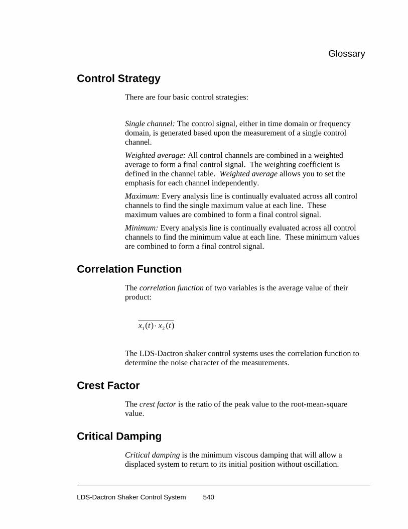
Glossary
LDS-Dactron Shaker Control System 540
Control Strategy There are four basic control strategies:
Single channel: The control signal, either in time domain or frequency domain, is generated based upon the measurement of a single control channel.
Weighted average: All control channels are combined in a weighted average to form a final control signal. The weighting coefficient is defined in the channel table. Weighted average allows you to set the emphasis for each channel independently.
Maximum: Every analysis line is continually evaluated across all control channels to find the single maximum value at each line. These maximum values are combined to form a final control signal.
Minimum: Every analysis line is continually evaluated across all control channels to find the minimum value at each line. These minimum values are combined to form a final control signal.
Correlation Function The correlation function of two variables is the average value of their product:
x t x t1 2( ) ( )⋅
The LDS-Dactron shaker control systems uses the correlation function to determine the noise character of the measurements.
Crest Factor The crest factor is the ratio of the peak value to the root-mean-square value.
Critical Damping Critical damping is the minimum viscous damping that will allow a displaced system to return to its initial position without oscillation.
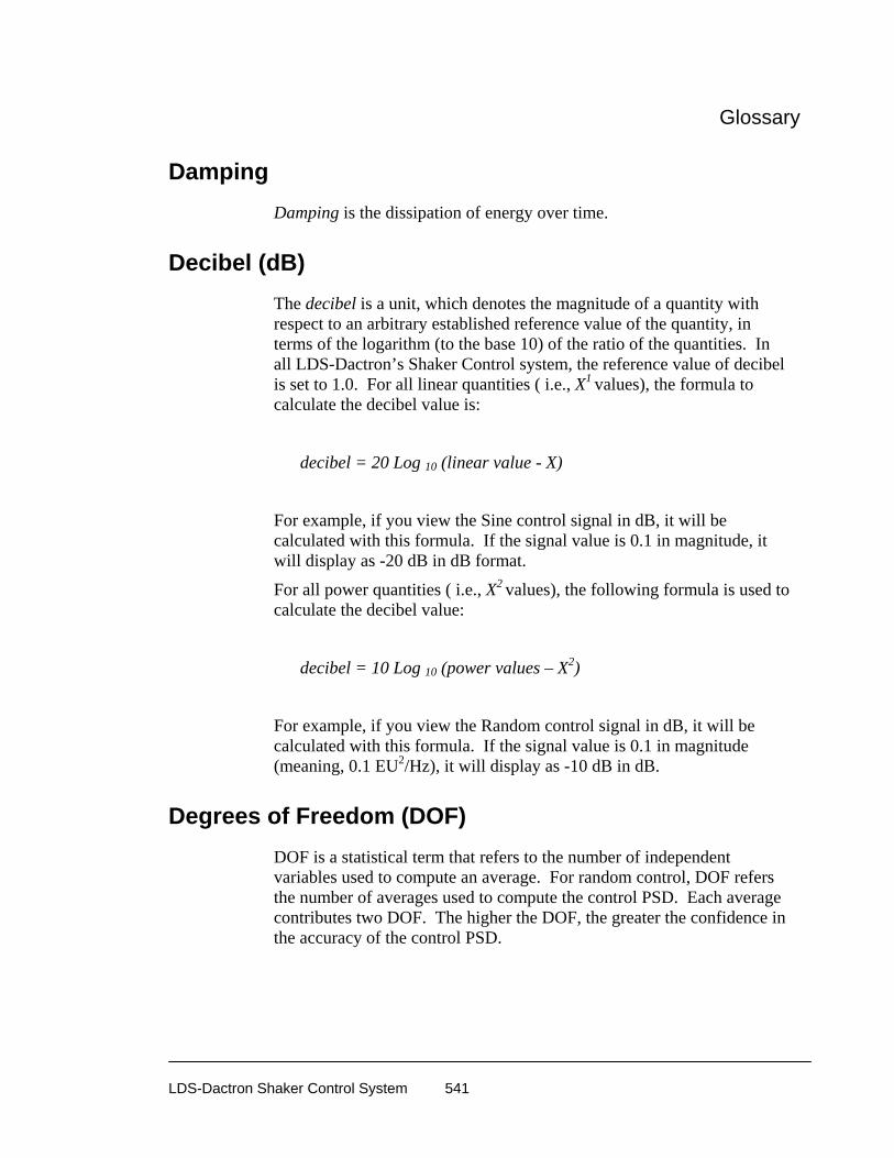
Glossary
LDS-Dactron Shaker Control System 541
Damping Damping is the dissipation of energy over time.
Decibel (dB) The decibel is a unit, which denotes the magnitude of a quantity with respect to an arbitrary established reference value of the quantity, in terms of the logarithm (to the base 10) of the ratio of the quantities. In all LDS-Dactron’s Shaker Control system, the reference value of decibel is set to 1.0. For all linear quantities ( i.e., X1 values), the formula to calculate the decibel value is:
decibel = 20 Log 10 (linear value - X)
For example, if you view the Sine control signal in dB, it will be calculated with this formula. If the signal value is 0.1 in magnitude, it will display as -20 dB in dB format.
For all power quantities ( i.e., X2 values), the following formula is used to calculate the decibel value:
decibel = 10 Log 10 (power values – X2)
For example, if you view the Random control signal in dB, it will be calculated with this formula. If the signal value is 0.1 in magnitude (meaning, 0.1 EU2/Hz), it will display as -10 dB in dB.
Degrees of Freedom (DOF) DOF is a statistical term that refers to the number of independent variables used to compute an average. For random control, DOF refers the number of averages used to compute the control PSD. Each average contributes two DOF. The higher the DOF, the greater the confidence in the accuracy of the control PSD.

Glossary
LDS-Dactron Shaker Control System 542
Demand Profile The demand profile is a description of the target that the control signal tries to achieve. The profile is defined in frequency domain for Random and Sine testing, and in time domain for Shock testing.
Deterministic Signals A deterministic signal is one whose value at any time can be predicted from its value at any other time. The sine and the shock outputs are deterministic signals. The random output is not a deterministic signal.
Displacement Displacement is a vector quantity that specifies magnitude and direction of change in position.
Distortion Distortion is an undesired change in a measured waveform. Noise and certain desired changes in the waveform, such as those resulting from modulation or detection, are not usually considered distortion.
Drive Voltage output of the controller used to drive the shaker system.
Drive Limit To protect the shaker or test article, a drive limit can be set so that the output can not exceed a defined voltage level.
Duration of Shock Pulse The duration of a shock pulse is the time required for the acceleration to rise and decay.

Glossary
LDS-Dactron Shaker Control System 543
Dynamic Range Dynamic range generally refers to the ratio of largest value to the smallest meaningful value in one measurement. For example, a 16-bit A/D converter has a theoretical dynamic range at 96 dB; a 20-bit converter has a theoretical dynamic range at 120 dB. The actual dynamic range of these converters is less due to the effects of noise and system distortion.
Dynamic range also applies to operations such as FFT transforms. A fixed-point DSP system usually provides very limited dynamic range (typically 50 to 90 dB). A floating-point DSP system can provide dynamic range up to 200 dB. See also: control dynamic range
Dwell Dwell is an output at a fixed frequency for an extended period of time in Sine. See also: resonance search and dwell
Equalization Equalization is the adjustment of the amplitude of the output such that the control signal matches a profile signal either in frequency domain or time domain. The equalization of the drive waveform can be accomplished directly by generating an error correction from the difference between the control and the profile. The equalization can also be accomplished indirectly through knowledge of the system’s frequency-response function magnitude.
The status message “Control Loop Closed” means the shaker/UUT load has been equalized. Conversely, “Control Loop Open” means that the shaker/UUT load has not yet been equalized.
Fourier Transform Fourier Transform is a bilateral transform typically used to convert quantities from time domain to frequency domain and vice versa. It is usually derived from the Fourier integral of a periodic function when the period grows without limit, and it is often expressed as a Fourier transform pair. In the classical sense, a Fourier transform takes the form of

Glossary
LDS-Dactron Shaker Control System 544
X f x t e dtj ft( ) ( )= −
−∞
∞
∫ 2π
Where
x(t) continuous time waveform
f analysis frequency
X(f) Fourier transform of x(t)
In the discrete or sampled sense, this can be expressed as
X k x k e j kn N
n
N
( ) ( ) /= −
=
−
∑ 2
0
1π
Where
x(k) samples of time waveform
n running sample index
N total number of samples or “frame size”
k finite analysis frequency, corresponding to
“FFT bin centers”
X(k) discrete Fourier transform
FFT The Fast Fourier Transform converts time domain data into frequency domain data. J. Cooley and J. Tukey invented it in 1965 as a quick method of computing the Fourier Transform. The speed and the computation accuracy of the FFT are crucial in the vibration control process. The LDS-Dactron Controller uses dedicated floating-point DSP chips to compute the FFT in real-time.
Fraction of Critical Damping The fraction of critical damping (damping ratio) for a system with viscous damping is the ratio of the actual damping coefficient c to the critical damping coefficient cc . In Shock Response Spectrum analysis, the fractional of critical damping is used as one of the input parameters for the analysis.

Glossary
LDS-Dactron Shaker Control System 545
Frequency Frequency is the number of oscillations or cycles per unit time. The unit cycle per second is called Hertz (Hz).
G G is the abbreviation for the acceleration due to gravity on earth. By international agreement, the value 980.665 cm/sec2 = 386.087 in./sec2 = 32.1739 ft/sec2 has been chosen as the standard acceleration due to gravity.
H (signal) H (signal) is the system transfer function.
H inverse (Hinv signal) The H inverse signal refers to the inverse of system transfer function.
Harmonic A harmonic is a sinusoidal quantity having a frequency that is an integral multiple of the frequency of a periodic quantity to which it is related. In Sine-on-Random, you may select narrowband sine signals correlated in a harmonic way.
High-pass filter A high-pass filter attenuates frequencies below the cutoff frequency while allowing frequencies above the cutoff frequencies to be passed.
Level Level is the test amplitude with respect to the Demand Profile. Test Level may be expressed in dB or Percent. For example, 0 dB means 100%, or full testing level; -20 dB means 10%, etc. In Random, the level is applied to the total RMS of the control signal. In Sine, the level is applied to the peak value (the amplitude) of the control signal.

Glossary
LDS-Dactron Shaker Control System 546
Level Event Level event is an entry in the schedule for a Random test. Level events set the demand control level for the demand profile and the duration of the level run.
Lines (frequency or spectral) The frequency lines, or spectral lines, define the number of frequency bins in the FFT computation. The test frequency bandwidth divided by the number of lines determines the frequency increment.
Line Abort Ratio The line abort ratio is the ratio of lines outside the abort limits to the total number of frequency lines. The line abort ratio is also applied to the alarm line detection. The line abort ratio sets the sensitivity of detecting an abort/alarm condition.
Linear System A system is linear if for every element in the system the response is directly proportional to the excitation. The dynamic properties of each element in the system can be represented by a set of linear differential equations with constant coefficients.
Linear Change Rate The amplitude level of the drive signal is updated by using linear correction increments when stepping between test levels.
Logarithmic Change Rate The amplitude level of the drive signal is updated by using logarithmic correction increments when stepping between test levels.
Loop Time The time between amplitude corrections is called the loop time. It is determined by the number of samples taken to define the control amplitude and the computations required to correct the drive waveform.

Glossary
LDS-Dactron Shaker Control System 547
A loop is a complete cycle from the correction of one drive waveform to the correction of the next drive waveform.
Low-Pass Filter A low-pass filter attenuates frequencies above the cutoff frequency while allowing frequencies below the cutoff frequencies to be transmitted.
Maximum Frequency In Sine testing, maximum frequency defines the upper frequency limit of the test. Sine output resolution is not related to maximum frequency.
In Random testing, maximum frequency stands for the useful frequency range available for the testing.
Monitor Channel The input channels of the controller can be defined as control, monitor or disabled. Channels defined as monitor channels can be used to measure the response of the test item, but are not included in the control process unless limiting (notching) is applied.
Narrowband Random Vibration Narrowband random vibration is random vibration having frequency components only within a narrow band. In the time domain, it appears as sine wave with amplitude varying in an unpredictable manner. Narrowband random vibration can co-exist with broadband random vibration in the Random-on-Random control system.
Narrowband Sine Vibration Narrowband sine vibration refers to the sine waveform in a Sine-on-Random vibration controller.
Natural Frequency The natural frequency of a spring mass system is the frequency at which the system tends to oscillate when excited by a disturbance. For a

Glossary
LDS-Dactron Shaker Control System 548
multiple degree-of-freedom system, the natural frequencies are the frequencies of the normal modes of vibration.
Node A node is a point, line, or surface in a standing wave where some characteristic of the wave field has essentially zero amplitude. It is important not to put a control signal sensor on a node location of the structure.
Noise Unwanted signal characteristics, which interfere with, or mask detection of the desired data, are considered noise. The noise character for all the channels is estimated in order to achieve high quality control.
Pane A Pane is a sub-division of a Window. Each display window can be divided into one, two or four panes. Each Pane can contain a complete graphical display.
Peak-to-Peak Value The peak-to-peak value of a signal is the difference between the maximum and minimum extremes of the quantity. For a sine wave, it is twice the zero-to-peak value.
Zero-to-Peak Value The zero-to-peak value is the maximum value of a signal with respect to the relative zero level of the quantity.
Power Spectral Density (PSD) Power spectral density (PSD) is a measure of intensity in the frequency domain. Mathematically, a PSD can be described as the mean-square response of an ideal narrowband filter to x(t), divided by the bandwidth ∆f of the filter in the limit as ∆f-> 0 at frequency f (Hz):

Glossary
LDS-Dactron Shaker Control System 549
PSD f
Xff
fLim( ) =−>∆
∆
∆0
2
In practice, the PSD is usually computed from the FFT spectra of a signal.
In the Random Control System, PSD is used to represent the control and input channel signals.
Pre-Test Pre-testing takes place before full level testing is started. During the pre-test, the control system measures input noise levels, checks that the a closed loop condition exists, and measures the system transfer function. Parameters such as the Ramp-up rate, initial drive voltage, and Response Level Goal can be adjusted to control the pre-test.
The pre-test is optional and can be skipped if a previously measured system transfer function is supplied.
Project A project is a collection of parameters that completely describe the testing environment. These parameters include:
Test Definition: maximum frequency, lines, sweep rate, channel tables, profiles, schedules, shaker limits, etc.
Windows environment: such as color, size, Pane attributes etc.
Data Set: all the signal content and other specified data.
Each project is saved to a single folder. The folder name combines the project name and an extension appended by the control system. The default extensions are “(RANDOM)” for Random project, “(SINE)” for Sine, “(SHOCK)” for Shock. See also the detailed description of project management in this document.

Glossary
LDS-Dactron Shaker Control System 550
Profile and Schedule One Demand Profile is associated with one Schedule. A project may contain multiple Demand Profiles and Schedules. Demand Profile sequencing is accomplished automatically without stopping the control loop or drive output.
Q (quality factor) The quality factor Q is a measure of the sharpness of a resonance. Q is inversely related to the damping ratio. The smaller the damping ratio, the larger the Q value. To control a high-Q structure with Random, increase the resolution (lines) in the control parameter. To control a high-Q structure with Sine, increase the compression rate or reduce the sweep speed.
Ramp-up rate The ramp-up rate refers to the speed at which the drive level will be increased during the initial stage of testing.
Once the system is in closed-loop operation, the level change rate will be defined by level change rate.
Because the initial ramp-up is a complicated process, only a rough measure, Fast or Slow, is offered for control of the ramp-up rate.
Random Vibration Random vibration can be identified by a time domain based signal whose magnitude is difficult to predict at any one instant, but whose frequency domain signature remains consistent. The instantaneous magnitude levels of the time domain are specified only by probability distributions giving the probable fraction of the total time that the magnitude (or some sequence of magnitudes) will lie within a specified range. Random vibration contains no periodic or quasi-periodic constitutes. If random vibration has instantaneous magnitudes that occur according to the Gaussian distribution, it is called Gaussian random vibration. This control system generates a Gaussian random drive signal. When sigma clipping is enabled, the drive signal will be truncated by a fixed magnitude.
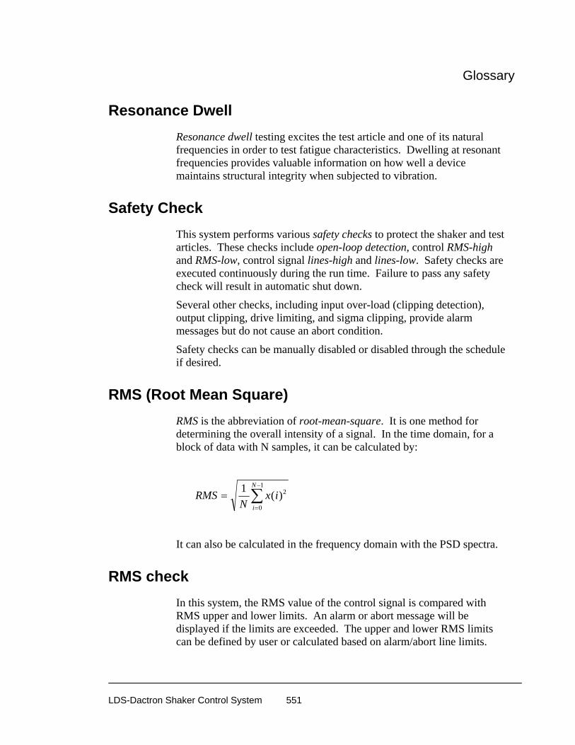
Glossary
LDS-Dactron Shaker Control System 551
Resonance Dwell Resonance dwell testing excites the test article and one of its natural frequencies in order to test fatigue characteristics. Dwelling at resonant frequencies provides valuable information on how well a device maintains structural integrity when subjected to vibration.
Safety Check This system performs various safety checks to protect the shaker and test articles. These checks include open-loop detection, control RMS-high and RMS-low, control signal lines-high and lines-low. Safety checks are executed continuously during the run time. Failure to pass any safety check will result in automatic shut down.
Several other checks, including input over-load (clipping detection), output clipping, drive limiting, and sigma clipping, provide alarm messages but do not cause an abort condition.
Safety checks can be manually disabled or disabled through the schedule if desired.
RMS (Root Mean Square) RMS is the abbreviation of root-mean-square. It is one method for determining the overall intensity of a signal. In the time domain, for a block of data with N samples, it can be calculated by:
RMS
Nx i
i
N
==
−
∑1 2
0
1
( )
It can also be calculated in the frequency domain with the PSD spectra.
RMS check In this system, the RMS value of the control signal is compared with RMS upper and lower limits. An alarm or abort message will be displayed if the limits are exceeded. The upper and lower RMS limits can be defined by user or calculated based on alarm/abort line limits.

Glossary
LDS-Dactron Shaker Control System 552
Schedule A test project is executed based on a pre-defined schedule. The schedule consists of a series of event entries such as the level event in Random or the sweep event in Sine. Certain commands can be incorporated into the schedule so that these operations are automatically performed.
Multiple entries can be defined in the schedule table. In Random and Shock schedules, these entries can be looped many times with Loop and End-Loop entries. There are also other ways to nest elements of loop logic. This provides a very flexible test set-up method.
In this control system, one schedule is associated with each profile. One project may contain many pairs of profiles and schedules.
Shock Response Spectrum (SRS) A Shock Response Spectrum is a plot of the maximum theoretical response of a simulated single degree-of-freedom system, as a function of its own natural frequency, to an applied shock. The response may be expressed in terms of acceleration, velocity or displacement.
The resolution of Shock Response Spectrum is characterized by Nth octave. Each single degree-of-freedom system is characterized by its damping factor and natural frequency.
Sigma Clipping In the Random control system, the Sigma Clipping value specifies the crest factor which is defined as the ratio of the Peak output drive level to RMS of the output drive level. With sigma clipping disabled, the crest factor of drive signal is a near-Gaussian distribution random signal around 4 to 5 standard deviations. When sigma clipping is applied, the crest factor will theoretically be equal to the sigma clipping number.
The output anti-aliasing filter has a smoothing effect that may change the final analog waveform so that the specified sigma clipping can not be precisely achieved. To reduce this effect, increase the Maximum Frequency parameters in the test.
Sigma clipping may be used to maximize the power capacity of the shaker. However, it may introduce broadband drive energy at frequencies above the control spectrum range.
Glossary
LDS-Dactron Shaker Control System 553
Spectrum A spectrum defines the amplitude of signal components as a function of their corresponding frequencies. That is, a spectrum defines a curve of signal amplitude versus frequency. A variety of spectra are used in the vibration control system. They include power spectral density, transfer function, and peak-spectrum (used in Sine).
Sweep Cycle In the Sine control system, a sweep cycle is defined as one complete sweep-up plus one complete sweep-down.
Sweep Direction In the Sine control system, the sweep direction is initialized in the sweep event. The sweep event can begin sweeping up or down in frequency. The sweep direction can be manually changed during the test.
Sweep Event In the Sine schedule, a sweep event defines the sweep range, starting frequency, starting sweep direction and the sweep duration. Multiple sweep events can be scheduled for a single test.
Sweep Rate In the Sine control system, sweep rate is the rate at which the frequency changes during a sweep. Sweep rate is defined in Octaves/min., for a log sweep, or in Hz/second for a linear sweep.
Sweep Type Both log and linear sweep types are available in the sine control system. For a log sweep, the sweep rate is defined in Octaves/minute. For a linear sweep, the sweep rate is defined in Hz/second.

Glossary
LDS-Dactron Shaker Control System 554
Tracking Filter In Sine, a bandpass filter is tuned so that its center frequency tracks the current operating frequency. A filter tuned in this way is called a tracking filter. A fixed-bandwidth tracking filter does not change bandwidth during the sweep. A proportional-bandwidth tracking filter will change bandwidth in proportion to the operating frequency.
A tracking filter can be enabled for each input channel.
See bandwidth, bandpass filter
Transmissibility Transmissibility is the non-dimensional ratio of the response amplitude of a system to the input amplitude. In this system, it can be calculated between any of enabled channels and/or the control signal.
Variance Variance is the square of the standard deviation. It is a measure of the variability of a signal. In Random PSD measurements, increases the Averaging Number reduces the spectrum variance.
Waterfall Plot A waterfall plot is a three dimensional plot. It typically represents a “stack-up” of a time or frequency function versus time or increment. A waterfall plot is used to study the characteristics of rotating machinery. For example, effects such as rotating imbalance, bearing misalignment, gear wear, bent shaft, cracked shaft, etc., can all be diagnosed by examining waterfall plots.
Waterfall Plus Slice Window A waterfall plus slice window includes 2 plots: a 3-dimensional plot on the bottom and a 2 dimensional plot on the top. The 3-dimensional plot can be either a multispectrum waterfall or a time waterfall plot. The 2
Glossary
LDS-Dactron Shaker Control System 555
dimensional plot is a slice through the waterfall plot. It can be either an intersection of the x axis, z axis or an order. By moving a cursor in the waterfall plot, the current slice can be viewed in the Slice window.
White Noise White noise is a random time domain signal that has a flat power spectral density.
Manual Revision History
LDS-Dactron Shaker Control System 556
12 License Agreement
If you keep the Software, you are agreeing to the terms of this Agreement. Use of the Software is subject to this agreement. If you do not agree to the terms of this Agreement, return this package to LDS for a refund. LDS grants you a non-exclusive right to use this copy of the Software and accompanying materials according to the following: You may:
a) use and install the Software on only one computer at a time; b) make one (1) copy of the Software for backup purposes; and c) transfer the Software from one computer to another so long as the Software is neither used on nor copied onto more than
one computer at a time. You may not:
a) modify, reverse engineer or copy (except for the backup copy) the Software or accompanying materials; b) rent or transfer the Software.
This license is not a sale. Title and copy rights to the Software and accompanying materials remains with LDS and its licensors. Any breach terminates this Agreement.
LIMITED WARRANTY, DISCLAIMER, AND LIMIT OF LIABILITY If at any time the software fails to operate as described in the documentation, simply return the original disks to LDS and LDS will replace the software at no charge to you or refund your purchase price, at LDS's option. LDS and its licensors do not warrant your data, that the Software will meet your requirements, or that the operation will be interrupted or error free. THE WARRANTY ABOVE IS IN LIEU OFF ALL OTHERS, EITHER EXPRESS OR IMPLIED, INCLUDING, BUT NOT LIMITED TO, THE IMPLIED WARRANTIES OF MERCHANTABILITY AND FITNESS FOR A PARTICULAR PURPOSE. SOME STATES HAVE LAWS THAT MAY RESTRICT OR PROHIBIT THE LIMITATIONS SET FORTH ABOVE AND YOUR RIGHTS UNDER LAW MAY VARY ACCORDING TO THE LAWS OF YOUR STATE. LDS and its licensers shall not be liable for any incidental or consequential damages, including loss of data, lost profits, cost of cover or other special or indirect damages. Your rights under law may vary. US GOVERNMENT RESTRICTED RIGHTS The software and documentation are provided with Restricted Rights. Use, duplication, or disclosure by the Government is subject to restrictions as set forth in subparagraph c(1)(ii) of the Rights in Technical Data and Computer Software clause at DFARS 252.227-7013 or subparagraphs c(1) and (2) of the Commercial Computer Software - Restricted Rights at 48 CFR 52.227-19 as applicable. Manufacturer is LDS, 47300 Kato Road, Fremont, CA 94538. This license agreement and limited warranty will be governed by the laws of the state of California. If any provision of this agreement is found void or unenforceable, the remainder of the agreement shall remain valid and enforceable.

Manual Revision History
LDS-Dactron Shaker Control System 557
13 Manual Revision History Date Manual Version Software
Version Contents added into the Manual in this version
Dec. 1997
1.00, 191 pages 1.0 Use light color in most of the pictures
Feb. 1998
1.10, 258 pages 1.1 SRS, Limiting added, Report improved, Calibration
April 1998
1.20, 284 pages 1.2 Digital I/O added, RSTD added, Double-side printed
Aug. 1998
2.0, 316 pages 2.0 Updated for Version 2.0 Software Enhancements, Reorganized Sections 4 & 5
Sept. 1998
2.1, 313 pages 2.1 Reviewed for consistency and readability. Made minor changes throughout.
May. 1999
3.0, 382 pages 3.0 Added Long Time History application. 16 Channel and Windows NT installations and version 3.0 features.
Nov. 1999
3.5, 368 pages 3.5 Added V3.5 features. Sections on Calibration and Troubleshooting moved to System Guide.
Dec 2000
3.8, 410 pages 3.8 Added V3.8 features – Signal Map, Angular Acceleration Units, Default Pane Setting, Sideband and Quality Factror Q Cursors.
Feb 2002
4.7, 488 pages 4.7 Added V4.7 features – Test ID, Recall Signals Manager, Test Setup Wizard, Waterfall and Color Maps, Setup Summary Window, Response Channel, TRUE DC Analysis Types, Sensor Calibration, Test Setup Icons, Memory Check, Email Notification, Online Tips, and Waveform Editor Edit Tools.
Dec 2002
4.71, 488 pages 5.0 Signal Map removed
May 2003
5.0, 509 pages 5.02 Added LTH Multiple Profile, FRF and Coherence, Non-acceleration Control, Active Reports, Signal Color Map, Annotation Control, Copy data or pane to clipboard, Numeric display, Channel Status Plots, Global Cursor Setup, Y Cursor, Passcode Administration, Waveform Editor changes
Dec 2003
5.5, 543 pages 5.5 Added License Key, Amplifier Control, Sine Oscillator, Template Report, PDF Report, Abort Limit Profile, Minimum frequency interval for resonances in RSTD, Inverse pulse as pretest profile, LTH Profile Schedule, Waveform Editor Profile Import Window, Export to Excel, Abort Action
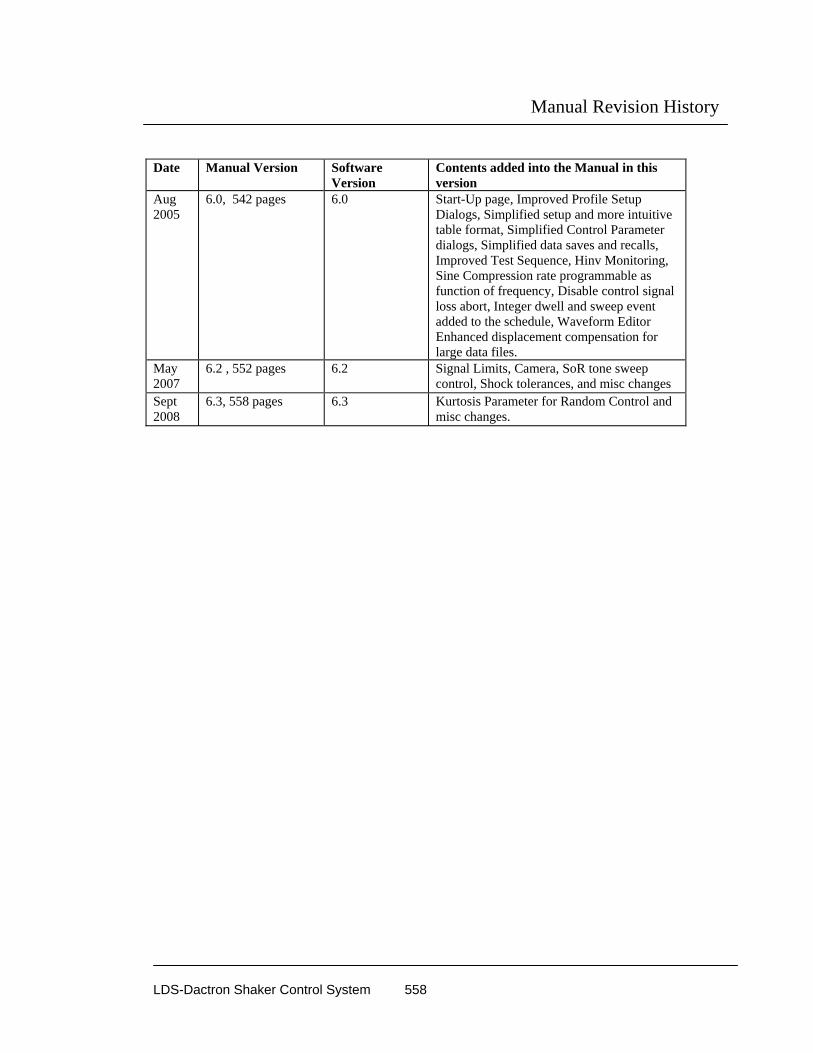
Manual Revision History
LDS-Dactron Shaker Control System 558
Date Manual Version Software
Version Contents added into the Manual in this version
Aug 2005
6.0, 542 pages 6.0 Start-Up page, Improved Profile Setup Dialogs, Simplified setup and more intuitive table format, Simplified Control Parameter dialogs, Simplified data saves and recalls, Improved Test Sequence, Hinv Monitoring, Sine Compression rate programmable as function of frequency, Disable control signal loss abort, Integer dwell and sweep event added to the schedule, Waveform Editor Enhanced displacement compensation for large data files.
May 2007
6.2 , 552 pages 6.2 Signal Limits, Camera, SoR tone sweep control, Shock tolerances, and misc changes
Sept 2008
6.3, 558 pages 6.3 Kurtosis Parameter for Random Control and misc changes.

Index
LDS-Dactron Shaker Control System 559
Index
A
Abort Action · 127 Abort Latency
Sine and RSTD · 176 Abort Limit · 546 Abort Limits · 502
Random and Mixed Mode · 147 Shock · 234, 235, 241, 260 Sine and RSTD · 189
Abort Rate · 533 LTH · 274 Random and Mixed Mode · 141 Sine and RSTD · 185
Abort Sensitivity · 533 Abort Tolerances · 533 Acceleration · 90, 534 Accelerometer · 534 Accelerometer Sensitivity · 96 Active Report · 421 Active Window · 366 ActiveX Signal Reader Enumerations · 486 ActiveX Signal Reader Methods · 480 ActiveX Signal Reader Properties · 483 Add and Delete Cursor Mark · 387 Add Cursor Icon · 434 Add Text Box Icon · 435 Adding ActiveX Signal Reader to a Project · 488 Adding Annotation · 458 Adding Cursor Marks · 452 Adding Signal to Display · 376 Alarm Tolerances · 534 Amplifier Control · 127 Amplitude · 534 Angular Acceleration Units · 98 Annotation · 458, 459 Anti-Aliasing Filter · 534 Anti-Resonance · 513, 534, 538 Auto Range Display · 377 Autosave · 41, 50 Averaging · 269, 309, 438, 535 Averaging Number · 219, 536
B
Bandwidth · 536, 538, 546, 554 Bandwidth, Fixed · 537 Bandwidth, Proportional · 537
C
Cache Signal Manager · 59 Calibration · 11 Calibration File · 11 Cascade · 365 Chamber Interface Setup · 115 Changing Y and X Scales · 446 Channel Parameters · 94, 95
Sine · 99 Channel Status Window · 352, 353, 370 Classical Shock Control · 516 Coherence · 114 COLA · 102 Compensation
LTH · 280, 289, 296, 297, 299 Shock · 232, 233, 237, 245, 247, 251, 258, 259,
261, 538 Waveform · 517
Composite Window · 360 Compression Rate · 176, 538 Consolidated · 42 Constant Output Level Adaptor · 102 Contents · 557, 558
Axes Scales · 382 Background Color · 382 Font · 382 Frame Color · 382 Grid · 381 Input Status · 384 Numerical Format · 382 Pane · 376 Selecting Signals · 376 Text · 382 Tic Mark · 381 Title · 381 X and Y Axis Range · 383 X –Auto Range Display · 377 X -Axis Format · 376 xTitle · 382 Y-Axis Format · 376 yTitle · 381
Control Dynamic Range · 539 Control Icons · 432 Control Loss Detection · 135, 136, 180 Control Panel
LTH · 348 Random and Mixed Mode · 332 Shock · 345 Sine and RSTD · 336
Control Parameters Icons · 432 LTH · 268, 271 Random and Mixed Mode · 129
Index
LDS-Dactron Shaker Control System 560
RSTD · 183 Shock · 218, 219, 221, 223, 224 Sine and RSTD · 175, 181 TTH · 227
Control Strategy · 540 Controls for LTH · 348 Controls for Mixed-mode · 335 Controls for Random and Mixed-mode · 333 Controls for Shock, SRS Synthesis, and TTH · 345 Controls for Sine and RSTD · 336, 337 Controls menu · 330 Coupling · 97, 110 Crest Factor · 151, 160, 540, 552 Critical damping coefficient · 498 Current Pane · 399, 415 Cursor
Harmonic · 456 Add Icon · 434 Adding Marks · 452 Delete Icon · 434 Find Nearest Peak or Valley · 394 Harmonic · 393, 455 Movement · 450 Moving the Readout · 451 Normal · 392 Peak · 393 Q Factor · 394 Quality Factor and Damping Readout · 454 Readout for RMS and Power · 452 Sideband · 393 Synchronized Dual Cursor Movement · 450 Synchronized Movement · 450 Valley · 393, 453
Cursor Global Setup · 394 Cursor Menu · 390 Cursor Movement · 450 Cursors
Add Mark · 387 Delete Mark · 387
D
Damping ratio · 498 Data Folder · 42 Data Format · 43 Decibel (dB) · 541 Decrease Demand Level Icon · 436 Decrease Frequency Icon · 438 Default Project · 38 Define a Project · 85 Degrees of Freedom (DOF) · 541 Delete Cursor Icon · 434 Desktop · 22 Detail View · 53 Digital Input · 313, 315, 316, 317, 321, 322, 323 Digital Output · 314, 315, 316 Displacement · 90
Display Selecti ng Signals · 376
Displays Acessing Contents · 462 Add Annotation · 387 Adding Annotation · 458 Auto Fit Y-Axis · 388 Axes Scales · 382 Background Color · 382 Change X Limits · 447 Change Y Limits · 447 Default Parameters · 386 Delete Annotation · 387 Font · 382 Frame Color · 382 Grid · 381 Numerical Format · 382 Text · 382 Tic mark · 381 Title · 381 X & Y Unit Labels and Plot Title · 460 X and Y Axis Range · 383 xTitle · 382 yTitle · 381 Zoom In · 387, 448 Zoom Out · 387, 448 Zoom Out Icon · 435
Drive · 542 Drive Limit · 131, 176, 184, 219, 269, 542 Dynamic Range · 543
E
Engineering Units · 89, 93 Acceleration · 90 Displacement · 90 Force · 90, 91 Level · 90 Sweep Mode · 91 Velocity · 90
Enum DATAFORMAT · 486 Enum WEIGHTING · 487 Enum WNDTYPE · 487 Equalization · 543 Eunm TRANSUNITS · 486 Export to Excel · 389
F
F Key Commands · 350 FFT · 544 File Management · 25 Filter Type for Sine · 176, 184 Find Nearest Peak or Valley · 394 Folder Append Mode · 42 Force · 90, 91

Index
LDS-Dactron Shaker Control System 561
Four-Pane Window · 364 Frequency · 545
G
GetData · 480, 481 GetEventInform · 480, 482 GetSliceValueArray · 480, 482 Go to here · 204 Graphical View · 53
H
H inverse (Hinv signal) · 545 Harmonic · 457 Harmonic Cursor · 457 Harmonic cursor setup · 396 Harmonic Cursors · 393, 455 Help
About · 433 About Icon · 437
Help Icon · 437 Hold Sweep Icon · 439
I
Increase Demand Level Icon · 436 Increase Frequency Icon · 439 Initial Ramp-Up Rate
Sine and RSTD · 175, 181, 182, 183 Input Channels · 95 Integer Sweep Event · 203
K
Kurtosis Parameter · 136
L
Level · 90, 545 Decrease Demand Icon · 436 Increase Demand Icon · 436 Set Demand Icon · 435
Level Event · 169, 263, 546 License Key · 5, 12 Limiting Profile
Random · 166 Sine · 196, 197, 198
Line Abort Ratio · 546 List View · 53 LoadSignal · 480
Log Sweep · 91
M
Making the Active Pane · 375 Manual Save · 49 Math Operations · 107 Mixed-mode Control · 502 Mouse Controls · 432, 446 Moving Pane Borders · 375 Moving the Cursor Readout · 451 MS-Word · 401, 404, 458 MS-Word Template · 407, 418 MTS AFU · 44, 287 MTS ATI · 44, 287 MTS ATI/AFU · 44, 287
N
New Project · 32, 38, 432 New Project · 72 New Project Icon · 433 Next Event in Schedule Icon · 436 Next Profile in Schedule Icon · 436 Non-Acceleration Control · 131, 177, 220, 269 Normal Cursor · 394, 454 Numeric Display · 355, 367
Signal property · 355, 367 Numerical Display
System Status · 355, 367 Numerical Indicator Settings · 355, 367
O
One- Pane Icon · 434 One-Pane Window · 362 On-Line Save Signals · 331 Open Project · 24, 37 Open Project Icon · 433 Output a Single Pulse Icon · 439 Output Channel · 99 Output Saved Results to MS-Word · 400, 428 Overwrite · 42
P
Pane · 360 Add Annotation · 387 Add Text Icon · 435 Annotation · 458 Auto Fit Y-Axis · 388 Border Movement · 461 Change X Limits · 447

Index
LDS-Dactron Shaker Control System 562
Change Y Limits · 447 Contents · 376, 378, 380, 381, 382, 384, 462 Contents Icon · 434 Current · 415 Default Parameters · 386 Delete Annotation · 387 Making Active Pane · 375 Moving Borders · 375 One-Pane Icon · 434 Y and X Unit Labels and the Plot Title · 460 Zoom In · 387, 448 Zoom Out · 387, 448 Zoom Out Icon · 435
Pane Default Parameters · 386 Pane Menu · 375 Parameter Summary Window · 430 Peak and Valley Cursors · 453 Peak Cursors · 393 Peak/Valley setup · 395 Post-Pulse Only Compensation · 238 Pre- and Post-Pulse Compensation · 237 Preferences
LTH · 273, 274 Random and Mixed Mode · 140, 142, 143 Shock · 228, 229 Sine · 187, 188 Sine and RSTD · 184, 185, 187
Pre-Pulse Only Compensation · 239 Pre-Test · 325, 549
Random and Mixed Mode · 137 Pre-Test Drive Pause · 347 Pre-Test Report · 325 Preview Recalled Signals · 53 Preview Test · 332 Profile
Block Diagram · 309, 310, 311, 361, 462 LTH · 275, 276, 277, 278, 280, 281 Mixed Mode · 156 Narrowband · 157, 158, 159 Narrowband and Tone · 165 Random · 144, 145, 148, 150, 151, 153, 154, 155,
156, 195, 196, 275, 436, 542, 545, 550 Shock · 230, 231, 232, 234, 235, 237, 240 Sine and RSTD · 188, 189, 190, 191, 192, 194,
195 SRS · 240, 241, 242, 244, 247, 248, 249 Tone · 162, 163, 164, 165 TTH · 251, 254, 255, 256, 258, 259, 260, 261, 262 Waveform Editor · 281, 283, 284, 286, 288, 289,
295, 296, 298 Project · 549
New · 32, 38, 72, 432 New Icon · 433 Open · 24, 37 Open Icon · 433 Running · 324 Save Icon · 434 Saving Defaults · 38
Project Folder · 25, 31, 37
Project Report · 418 Project Sequence · 311, 312, 356
Q
Q (quality factor) · 550 Q Factor · 394, 454, 455 Quick Report · 419, 437 Quick Report Icon · 437
R
Ramp-up rate · 549, 550 Random Vibration Control · 499 Recall · 52 Recall Data
pop-up window · 58 Recall Signal Manager · 52, 53 Recall Signals · 377 Recalled Signals · 59 Release Sweep Icon · 439 Report
Options · 419 Output Saved Results · 428 Pre-Test · 325 Quick Report Icon · 437 RSTD · 421
Report Functions · 398 Report Menu · 414 report template · 424 Reports
Creating · 359 Project · 418
Reset Averaging Icon · 438 RMS (Root Mean Square) · 551 RPCIII · 44, 287 RSM · 52 Run a Project · 324 Run Folders · 32, 40, 48 Run Log · 353, 373 Run Process · 325
S
Save As · 38, 39, 312, 434 Save Project Icon · 434 Save Results · 170, 173, 205, 207, 264, 267, 307, 331 Save Results Icon · 436 Save Signal Manager · 41 Save Signals · 45 Schedule
Next Event in Schedule Icon · 436 Schedule
LTH · 307
Index
LDS-Dactron Shaker Control System 563
Mixed Mode · 174 Next Event in Schedule Icon · 436 Random · 168, 169, 172, 173, 263, 266 RSTD · 208, 209, 210, 211, 212, 213, 214 Shock · 262, 263, 264, 266, 267 Sine and RSTD · 199, 200, 201, 203, 204, 206,
207 Schedule
Random · 439 Schedule
Random · 550 Schedule
Random · 550 Schedule
Random · 552 Screen Bitmap · 173, 400, 413 Screens
Creating · 359 SDF · 44, 287 Set Demand Level Icon · 435 Set Frequency Icon · 438 Set Update H Ratio Icon · 440, 441 Setting Y and X Unit Labels · 460 Shaker Parameters · 91
Maximum Acceleration · 94 Maximum Drive Voltage · 94 Maximum Velocity · 94 Min and Max Drive Frequency · 94 Positive and Negative Displacement Limits · 94
Shock Response Spectrum (SRS) · 552 Sideband Cursors · 393 Sigma Clipping · 131, 552 Signal Files · 48, 63 Signal Group · 50 Signal Manager · 40 Signal Name · 49 Signals · 63
Math Operations · 107 Recall · 377 Save Icon · 436 Saving · 170, 173, 205, 207, 264, 267, 307, 331 Special Displays · 377 Time Characteristics · 108 Types for LTH · 69 Types for Random and Mixed Mode · 65 Types for Shock · 68 Types for Sine and RSTD · 66, 67 Units · 64
Sine COLA Output · 102 Sine Displacement · 91 Sine Oscillator · 175, 183, 184, 336 Single Degree-of-Freedom System · 498 Special Signal Displays · 377 Special Signals · 106 Start Request · 327 Start-Up Page · 73 Status Bar · 365 Status Display Setup · 369
Sweep Down Icon · 438 Sweep Type for Sine · 176 Sweep Up Icon · 438 Swept Sine Vibration Control · 505 Synchronized Cursor
Movement · 450 Synchronized Dual Cursor
Movement · 450
T
Template Report · 427 Test ID · 416, 417 Tile · 365 Time Characteristics · 108 Time Stamp · 42 Tool Bar · 24, 365, 432, 434 Tracking Filter · 508, 509, 512, 536, 554 Transmissibility · 554 Troubleshooting · 322, 557 Two-Pane Horizontal Window · 363 Two-Pane Vertical Window · 363, 364
U
uninstall · 10 Unit Under Test · 1, 332, 497
V
Valley Cursors · 393 Velocity · 90 Visual Basic · 495 Visual C++ · 488
W
Waterfall · 554 Waterfall Plus Slice · 554 Weighted Average
LTH · 269 Random and Mixed Mode · 130 Sine and RSTD · 176
Weighting · 97, 130, 176, 269, 349, 440, 535, 540 Window Menu · 362 Window Selector · 435 Windows · 360
Active · 366 Block Diagram · 361 Cascading · 365 Channel Status · 352, 370 Composite · 360 Creating · 359

Index
LDS-Dactron Shaker Control System 564
Four-Pane · 364 One-Pane · 362 Run Log · 353, 373 Selector Box · 435 Tiling · 365 Two-Pane Horizontal · 363 Two-Pane Vertical · 363
Word 2000 · 402, 404, 405, 407 Working with Windows and Panes · 446
X
X-axis · 392, 447 X-Axis Format · 376
Y
Y Cursor · 393 Y-axis · 388, 447, 448 Y-Axis Format · 376
Z
Zoom In · 387, 448 Zoom Out · 387 Zoom Out Icon · 435