Embed Size (px)
Citation preview

8.1.2015 BRG
PREMANT district heating pipe PRE
Subject to technical changes
Table of Contents
6.0 Table of Contents
6.100 System description6.105 Medium pipe6.106 Heat insulation, casing pipe, monitoring wires6.115 District heating pipe – UNO
6.200 Planning, design engineering6.200 Pressure drop6.210 Heat loss, insulation thickness 16.211 Heat loss, insulation thickness 26.212 Heat loss, insulation thickness 36.230 Pipe routing6.231 Maximum installed length, Lmax6.232 Naturalfixedpoint,NFP6.240 Maximum permitted coverage height, Hmax6.241 Installation without pre-stressing, Lmax, insulation thickness 16.242 Installation without pre-stressing, Lmax, insulation thicknesses 2 and 36.243 Thermal pre-stressing6.244 Installation with thermal pre-stressing, DN 20 - DN 300, insulation thickness 16.245 Installation with thermal pre-stressing, DN 20 - DN 300, insulation thickness 26.246 Installation with thermal pre-stressing, DN 350 - DN 500, insulation thicknesses 1 and 26.247 Installation with thermal pre-stressing, DN 20 - DN 250, insulation thickness 36.250 Impeded expansion6.251 Impeded expansion; expansion up to 90 °C, DN 20 - DN 125, insulation thickness 2, permitted without pre-stressing6.252 Impeded expansion; expansion up to 90 °C, DN 20 - DN 125, insulation thickness 3, permitted without pre-stressing6.253 Freeexpansion6.260 Expansion components; L, Z and U bends6.261 Expansion components, transverse shift6.262 Positioning of expansion pads6.263 Installation guidelines, sheet 16.264 Installation guidelines, sheet 26.265 Installation guidelines, sheet 36.266 Installation guidelines, sheet 4
6.300 Components6.300 District heating pipe – UNO6.304 Elbow pipe6.305 Bend, with equal legs 90°6.306 Bend, with equal legs 90° short6.307 Bend, with equal legs 45°6.308 Bend, with equal legs 45° short6.310 Bend, 1.0 x 2.0 m 90°6.312 T-piece, angled 45°; Insulation thickness 16.313 T-piece, angled 45°; Insulation thickness 26.314 T-piece, angled 45°; Insulation thickness 36.316 Parallel T-piece; Insulation thickness 16.317 Parallel T-piece; Insulation thickness 2
6.0
The design engineering worksheets are not included in this catalogue.
Please contact your BRUGG Partner in this regard.

8.1.2015 BRG
PREMANT district heating pipe PRE
Subject to technical changes
6.0
Table of Contents
6.318 Parallel T-piece; heating, insulation thickness 36.320 Fixedpoint;thermallyandelectricallyseparated,insulationthickness26.321 Reduction piece6.322 Vent6.323 Drainer6.325 Fittingsinstalledintheground;description,installationandoperatinginstructions6.330 Ball valve6.332 Ball valve with 2 vents6.333 Ball valve with 1 vent6.334 Ball valve for installation in the ground, installation diagram6.335 Accessories:shut-offfitting,ballvalve6.340 Joint; shrink sleeves6.342 Joint, shrink-on reduction sleeve/end sleeve6.345 Brugg VISUCON6.350 EWELCONelectro-weldingjoint,systemdescription6.351 EWELCON electro-welding joint, technical data6.352 EWELCON-S electro-welding joint6.353 EWELCON-S electro-welding joint6.354 Fittingbend6.355 Wall sealing ring, pipe warning tape6.356 Shrink-on closure6.357 Rigid foam beam6.360 Ring seal6.365 Expansion pad
6.400 Transport and storage6.403 Storage of preformed parts6.410 Assemblyfoam
6.500 Underground construction, installation6.500 Underground construction work, installation6.501 Underground construction work, installation6.502 Fillinginthepipetrenches6.505 House lead-in, wall seal – neoprene rubber6.510 Installation instructions6.515 Concreteblockforfixedpoint,formaximumfixedpointforces6.520 Sectional drainage, sectional venting6.525 Underground construction work for ball valve, shafts with drive-over cast cover6.530 Tappingtechnology,systemdescription6.531 Tappingtechnology,dimensionsandmeasurements6.532 Tappingtechnology,weldseampreparationandstructure6.533 Tappingtechnology,junctionbranchattopwith45°PREbend6.534 Tappingtechnology,junctionbranchattopwith45°weldedbend6.535 Tappingtechnology,junctionbranchatbottomwith45°PREbend6.536 Tappingtechnology,junctionbranchatbottomwith45°weldedbend6.537 Tappingtechnology,junctionbranchattopwith90°PREbend

8.1.2015 BRG
PREMANT district heating pipe PRE
Subject to technical changes
System description
1. General
PREMANTistheprotectednameforapre-insulatedsteelpipesystemusedtotransportdistrictheat.Itisapipesystemfordirectinstallationintheground,withoutchannels.Thesystemhasprovenitsexcellenceoverseveraldecadesandisnowrecognizedastheindustrystandardfornormal cases.
Depending on the purpose of use, PREMANT district heating pipe has a medium pipe made of steel, either welded, seamless or galvanized, or made of stainless steel. This makes PREMANT districtheatingpipesuitabletotransportheatingwater,domestichotwater,water/glycolmix-ture,condensatesandotherfluids,butnotforsteam.(withobservationofthetemperature)
HeatinsulationforPREMANTdistrictheatingpipeisperformedbyarigidpolyurethanefoamwhich can withstand temperatures of up to 144 °C. PE-HD casing pipe provides external protec-tion.Allthreecomponentsformonefixedunit,sothispipesystemisamemberofthecompos-itepipefamily.
PREMANT district heating pipe is available in three categories of insulation thickness. Depending on the dimensions, the pipe construction units can be supplied in lengths of 6+12m(or16m).Theconstructionunitsandallassociatedpreformedpartssuchasbends,T-piecesandfixedpoints,etc.,areprefabricatedinthefactory.Theresultisamodularsystemwhichiscorrespondinglyeasytoplanandinstall.
All the components are connected together on site with circumferential seams. Supplemen-taryinsulationofthetheweldseamandtheweld-onendsisprovidedbymeansofjoints.Thesupplementaryinsulationworkisusuallycarriedoutbysystemsuppliersorqualifiedspecialistcompaniesonourbehalf.Duringtheplanningphase,weoffersupportbasedonoursystemexperiencetosystemuserswhorequestthis.
PREMANTdistrictheatingpipe,andthepreformedpartsandfittings,aremanufacturedaccordingtothelateststandards(EN253,448,488and489).
All the illustrations are schematic representations that do not correspond to the original components in every detail.
2. Range of applications
Max. temperature for continuous operation TBmax:144°C(160°C)Max. permitted operating pressure p: 25 bar
6.100

8.1.2015 BRG
PREMANT district heating pipe PRE
Subject to technical changes
System description
6.105
1. Medium pipe
Bars: steel pipes with longitudinal or helical seam welds Quality: Ø≤323.9mmP235TR1orP235GHasper;EN10220/EN10217-1 Ø>323.9mmP235GHasper;EN10220/EN10217-2 Standard: EN 253 Testcertificate: EN10204-3.1 Weldingbevel: Wallthickness>3.2mmacc.toDIN2559-1Index21and22
Preformed parts: T-piecesareflared,fromlongitudinalseam-weldedsteelpipes,ormadeofweldedt-piecesacc.toEN10253; material is the same as for straight welded pipes. Quality: P235TR1orP235GHasper;EN10220/EN10217 Standard: EN 448 Testcertificate: EN10204-3.1 Weldingbevel: Wallthickness>3.2mmacc.toDIN2559-1Index21and22
Bends, DN 20 - DN 200aremadeofcold-bent(seamlessorwelded)steelpipes or with a welding elbow acc. to EN 10253. Quality: P235TR1orP235GHasper;EN10220/EN10217 Standard: EN 448 Factorycertificate: EN10204-2.2 Acceptancetestcertificate: EN10204-3.1 Weldingbevel: Wallthickness>3.2mmacc.toDIN2559-1Index21and22
Bends, DN 250 - DN 1000 are made of welded bends acc. to EN 10253 with weld-on pipe ends. Quality: P235GHorP235TR1/TR2 Standard: EN 448 Factorycertificate: EN10204-2.2 Acceptancetestcertificate: EN10204-3.1 Weldingbevel: Wallthickness>3.2mmacc.toDIN2559-1Index21and22
Note:ToensurethelongevityofPREMANTplasticsheathingpipesystems,itisimportanttomakesuretheheatingwaterisofsufficientquality.Topreventmagnetiteformation(iron(II,III)oxide)andcalcificationinparticular,therequirementsofVDI2035,AGFWFW510andEN12953-10mustbemet.Beforecommissioning,anewly-installedheatdistributionnetwork,withoutaheatexchangerifpossible,shouldbecircu-latedandsuspendedsolidsmustberemovedbymeansofasuitablefiltersystem.Thisprocessshouldalsoberepeatedaftereveryexpansionofthenetworkoreveryrepair.

8.1.2015 BRG
PREMANT district heating pipe PRE
Subject to technical changes
System description
6.106
4. Monitoring wires
Brandessystem: 1xCrNi,red,insulatedandperforated,Ø0.5mm/0.2mm2
1xCu,green,insulated,Ø0.8mm/0.5mm2
Nordicsystem: 1xCublank:1.5mm2 1 x Cu tinned: 1.5 mm2
Task: Identificationandlocationofmoisturebymeansofresistanceorpulsemeasurements
2. Thermal insulation
Material: Polyurethanefoam(pentane-blown),manufacturedfrom3components: polyol,isocyanateandcyclopentane High-pressure plants are used for mixing and metering.
2.1 Supplementary insulation
Standard: EN 489Execution: -Executedbytrainedinstallationstaff -Polyurethanefoamisusedtofoamandsealthejoints - Sealing with shrink-on sleeve or electro-welding joint - Connecting the monitoring wires - Installing the expansion pads, consisting of an elastic foam material which is resistant to ageing
3. Casing pipe
Quality: PE-HD,GM5010T3orequivalentStandard: EN 253Factorycertificate: EN10204-2.2
PUR insulation Reference temperature °C PREMANT value Test standard
Compressionstrength - ≥0.3MPa EN253
Thermalconductivity 50 ≤0.0260W/mK DIN52612
Percentageofclosedcells - ≥96%
Waterabsorptionafter24hours - ≤10%
Dimensions of PE-HD casing pipes
Outer ø Min. wall thickness
Pipes/Bends/T-pieces
mm mm
400 5.3
450 5.6
500 6.3
560 7.0
630 7.6
670 8.0
710 8.7
800 9.0
900 10.1
1000 11.2
1100 12.0
1200 12.8
Dimensions of PE-HD casing pipes
Outer ø Min. wall thickness
Pipes Bends/T-pieces
mm mm mm
90 3.0 4.0
110 3.0 4.0
125 3.0 4.0
140 3.0 4.0
160 3.0 4.0
180 3.0 4.0
200 3.2 4.0
225 3.5 4.0
250 3.6 5.0
280 4.4 5.0
315 4.5 6.3
355 5.1 5.1

8.1.2015 BRG
PREMANT district heating pipe PRE
Subject to technical changes
District heating pipe – UNO
6.115
D = outer diameter of casing piped = outer diameter of medium pipe
L
200
Dd
st
Nominal Steel pipe Insulation thickness 1 Insulation thickness 2 Insulation thickness 3 Standard
width d x s D D D length
DN mm mm kg/m mm kg/m mm kg/m m
20 26.9 x 2.6 90 2.7 110 3.1 125 3.4 6
25 33.7 x 2.6 90 3.1 110 3.5 125 3.8 6
32 42.4 x 2.6 110 4.0 125 4.3 140 4.7 6 / 12
40 48.3 x 2.6 110 4.4 125 4.7 140 5.0 6 / 12
50 60.3 x 2.9 125 5.8 140 6.1 160 6.6 6 / 12
65 76.1 x 2.9 140 7.1 160 7.6 180 8.2 6 / 12
80 88.9 x 3.2 160 9.0 180 9.6 200 10.3 6 / 12
100 114.3 x 3.6 200 13.0 225 13.9 250 15.0 6 / 12 / 16
125 139.7 x 3.6 225 15.9 250 16.9 280 18.7 6 / 12 / 16
150 168.3 x 4.0 250 20.5 280 22.3 315 24.0 6 / 12 / 16
200 219.1 x 4.5 315 30.5 355 32.5 400 35.8 6 / 12 / 16
250 273.0 x 5.0 400 43.5 450 47.0 500 51.3 6 / 12 / 16
300 323.9 x 5.6 450 56.2 500 60.5 560 66.1 6 / 12 / 16
350 355.6 x 5.6 500 63.7 560 69.3 630 76.3 6 / 12 / 16
400 406.4 x 6.3 560 81.0 630 88.0 670 92.4 6 / 12 / 16
450 457.2 x 6.3 630 93.5 670 97.9 710 103.1 6 / 12 / 16
500 508.0x6.3 710(670) 108.3 800 118.6 900 133.1 6/12/16
600 610.0 x 7.1 800 140.0 900 154.5 1000 170.7 6 / 12 / 16
700 711.0 x 8.0 900 180.3 1000 196.5 1100 213.5 6 / 12 / 16
800 813.0 x 8.8 1000 223.8 1100 240.8 1200 259.4 6 / 12 / 16
900 914.0 x 10.0 1100 279.6 1200 298.2 - - 6 / 12
1000 1016.0 x 11.0 1200 337.1 - - - - 6
PREMANT
s = wall thickness of medium pipet = insulation thickness
Figuresinmm
Volume
Inner pipe
l/m
0.37
0.67
1.09
1.46
2.33
3.88
5.35
9.01
13.79
20.18
34.67
54.33
76.80
93.16
121.80
155.25
192.75
278.80
379.37
496.98
627.72
776.00
We will deliver different dimensions on request.

8.1.2015 BRG
PREMANT district heating pipe PRE
Subject to technical changes
Pressure drop chart
6.200
Flow
rate
m [
kg/h
]
1000000
500000
400000
300000
200000
100000
50000
40000
30000
20000
10000
5000
4000
3000
2000
1000
500
400
5
50 100
10
200 300 500 1000 2000 3000 5000
20 30 50 100 200 300 500
Pa/m
2.8 m/s
2.4 m/s
2.0 m/s
1.8 m/s
1.6 m/s
1.4 m/s
1.2 m/s
1.0 m/s0.8 m
/s0.6 m/s
0.5 m/s0.4 m
/s
21.6 mm(DN20)
29.1 mm(DN25)
37.2 mm(DN32)
43.1 mm(DN40)
54.5 mm(DN50)
70.3 mm(DN65)
82.5 mm(DN80)
107.1 mm(DN100)
132.5 mm(DN125)
160.3 mm(DN150)
mm WS/m
Pressure loss ∆p
Water temperature 80 °CSurface roughness e = 0.045 mm(1mmWS=9.81Pa)
Q · 860m ≈ ∆T
m = Flowrateinkg/hQ = Power requirement in kW∆T= Temperaturedifference,VL(flow)/RL(return)in°C
344.4 mm(DN350)
312.7 mm(DN300)
263.0 mm(DN250)
210.1 mm(DN200)
Watervelocity
3.6 m/s
3.2 m/s

8.1.2015 BRG
PREMANT district heating pipe PRE
Subject to technical changes
Heat losses q [W/m] for one pipe
PREMANT
26.9 - 90
33.7 - 90
42.4 - 110
48.3 - 110
60.3 - 125
76.1 - 140
88.9 - 160
114.3 - 200
139.7 - 225
168.3 - 250
219.1 - 315
273.0 - 400
323.9 - 450
355.6 - 500
406.4 - 560
457.2 - 630
508.0 - 710
610.0 - 800
711.0 - 900
813.0 - 1000
914.0 - 1100
1016.0 - 1200
U-value Average temperature between VL/RL TB [°C]
W/mK 50 °C 60 °C 70 °C 80 °C 90 °C 100 °C 110 °C 120 °C 130 °C
0.1292 5.2 6.5 7.8 9.0 10.3 11.6 12.9 14.2 15.5
0.1572 6.3 7.9 9.4 11.0 12.6 14.2 15.7 17.3 18.9
0.1607 6.4 8.0 9.6 11.2 12.9 14.5 16.1 17.7 19.3
0.1843 7.4 9.2 11.1 12.9 14.7 16.6 18.4 20.3 22.1
0.2054 8.2 10.3 12.3 14.4 16.4 18.5 20.5 22.6 24.6
0.2410 9.6 12.0 14.5 16.9 19.3 21.7 24.1 26.5 28.9
0.2484 9.9 12.4 14.9 17.4 19.9 22.4 24.8 27.3 29.8
0.2599 10.4 13.0 15.6 18.2 20.8 23.4 26.0 28.6 31.2
0.3002 12.0 15.0 18.0 21.0 24.0 27.0 30.0 33.0 36.0
0.3557 14.2 17.8 21.3 24.9 28.5 32.0 35.6 39.1 42.7
0.3887 15.5 19.4 23.3 27.2 31.1 35.0 38.9 42.8 46.6
0.3779 15.1 18.9 22.7 26.5 30.2 34.0 37.8 41.6 45.3
0.4342 17.4 21.7 26.0 30.4 34.7 39.1 43.4 47.8 52.1
0.4239 17.0 21.2 25.4 29.7 33.9 38.2 42.4 46.6 50.9
0.4514 18.1 22.6 27.1 31.6 36.1 40.6 45.1 49.6 54.2
0.4548 18.2 22.7 27.3 31.8 36.4 40.9 45.5 50.0 54.6
0.4413 17.7 22.1 26.5 30.9 35.3 39.7 44.1 48.5 53.0
0.5380 21.5 26.9 32.3 37.7 43.0 48.4 53.8 59.2 64.6
0.6097 24.4 30.5 36.6 42.7 48.8 54.9 61.0 67.1 73.2
0.6840 27.4 34.2 41.0 47.9 54.7 61.6 68.4 75.2 82.1
0.7550 30.2 37.7 45.3 52.8 60.4 67.9 75.5 83.0 90.6
0.8315 33.3 41.6 49.9 58.2 66.5 74.8 83.1 91.5 99.8
Heat lossInsulation thickness 1
6.210
Typeofinstallation: 2-pipe,laidinthegroundPipe distance: a = 0.20 mGroundtemperature: TE = 10 °CCoverage height: H = 0.8 mSoilconductivity: lE = 1.2W/mKConductivityofPEjacket: lPE = 0.4W/mKConductivityofPURfoam: lPUR = 0.0260W/mK
a
H
TE
lE
Heat loss during operation: q = U · (TB - TE) [W/m] U = Heattransfercoefficient[W/mK]TB = AveragetemperaturebetweenVL/RL[°C]TE = Averagegroundtemperature[°C]
8.1.2015 BRG
PREMANT district heating pipe PRE
Subject to technical changes
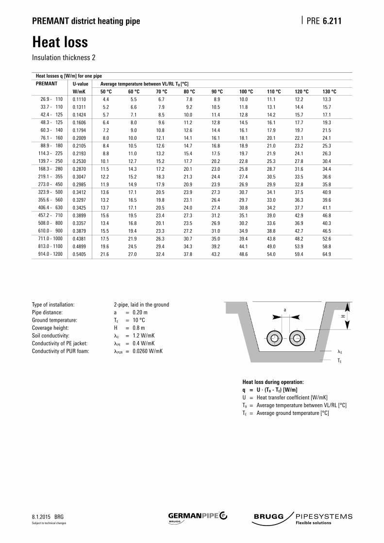
Heat lossInsulation thickness 2
6.211
Heat loss during operation: q = U · (TB - TE) [W/m] U = Heattransfercoefficient[W/mK]TB = AveragetemperaturebetweenVL/RL[°C]TE = Averagegroundtemperature[°C]
U-value Average temperature between VL/RL TB [°C]
W/mK 50 °C 60 °C 70 °C 80 °C 90 °C 100 °C 110 °C 120 °C 130 °C
0.1110 4.4 5.5 6.7 7.8 8.9 10.0 11.1 12.2 13.3
0.1311 5.2 6.6 7.9 9.2 10.5 11.8 13.1 14.4 15.7
0.1424 5.7 7.1 8.5 10.0 11.4 12.8 14.2 15.7 17.1
0.1606 6.4 8.0 9.6 11.2 12.8 14.5 16.1 17.7 19.3
0.1794 7.2 9.0 10.8 12.6 14.4 16.1 17.9 19.7 21.5
0.2009 8.0 10.0 12.1 14.1 16.1 18.1 20.1 22.1 24.1
0.2105 8.4 10.5 12.6 14.7 16.8 18.9 21.0 23.2 25.3
0.2193 8.8 11.0 13.2 15.4 17.5 19.7 21.9 24.1 26.3
0.2530 10.1 12.7 15.2 17.7 20.2 22.8 25.3 27.8 30.4
0.2870 11.5 14.3 17.2 20.1 23.0 25.8 28.7 31.6 34.4
0.3047 12.2 15.2 18.3 21.3 24.4 27.4 30.5 33.5 36.6
0.2985 11.9 14.9 17.9 20.9 23.9 26.9 29.9 32.8 35.8
0.3412 13.6 17.1 20.5 23.9 27.3 30.7 34.1 37.5 40.9
0.3297 13.2 16.5 19.8 23.1 26.4 29.7 33.0 36.3 39.6
0.3425 13.7 17.1 20.5 24.0 27.4 30.8 34.2 37.7 41.1
0.3899 15.6 19.5 23.4 27.3 31.2 35.1 39.0 42.9 46.8
0.3357 13.4 16.8 20.1 23.5 26.9 30.2 33.6 36.9 40.3
0.3879 15.5 19.4 23.3 27.2 31.0 34.9 38.8 42.7 46.5
0.4381 17.5 21.9 26.3 30.7 35.0 39.4 43.8 48.2 52.6
0.4899 19.6 24.5 29.4 34.3 39.2 44.1 49.0 53.9 58.8
0.5405 21.6 27.0 32.4 37.8 43.2 48.6 54.0 59.4 64.9
Typeofinstallation: 2-pipe,laidinthegroundPipe distance: a = 0.20 mGroundtemperature: TE = 10 °CCoverage height: H = 0.8 mSoilconductivity: lE = 1.2W/mKConductivityofPEjacket: lPE = 0.4W/mKConductivityofPURfoam: lPUR = 0.0260W/mK
Heat losses q [W/m] for one pipe
PREMANT
26.9 - 110
33.7 - 110
42.4 - 125
48.3 - 125
60.3 - 140
76.1 - 160
88.9 - 180
114.3 - 225
139.7 - 250
168.3 - 280
219.1 - 355
273.0 - 450
323.9 - 500
355.6 - 560
406.4 - 630
457.2 - 710
508.0 - 800
610.0 - 900
711.0 - 1000
813.0 - 1100
914.0 - 1200
a
H
TE
lE

8.1.2015 BRG
PREMANT district heating pipe PRE
Subject to technical changes
Heat lossInsulation thickness 3
6.212
Heat loss during operation: q = U · (TB - TE) [W/m] U = Heattransfercoefficient[W/mK]TB = AveragetemperaturebetweenVL/RL[°C]TE = Averagegroundtemperature[°C]
U-value Average temperature between VL/RL TB [°C]
W/mK 50 °C 60 °C 70 °C 80 °C 90 °C 100 °C 110 °C 120 °C 130 °C
0.1019 4.1 5.1 6.1 7.1 8.2 9.2 10.2 11.2 12.2
0.1186 4.7 5.9 7.1 8.3 9.5 10.7 11.9 13.0 14.2
0.1294 5.2 6.5 7.8 9.1 10.3 11.6 12.9 14.2 15.5
0.1442 5.8 7.2 8.7 10.1 11.5 13.0 14.4 15.9 17.3
0.1562 6.2 7.8 9.4 10.9 12.5 14.1 15.6 17.2 18.7
0.1754 7.0 8.8 10.5 12.3 14.0 15.8 17.5 19.3 21.0
0.1857 7.4 9.3 11.1 13.0 14.9 16.7 18.6 20.4 22.3
0.1930 7.7 9.7 11.6 13.5 15.4 17.4 19.3 21.2 23.2
0.2162 8.6 10.8 13.0 15.1 17.3 19.5 21.6 23.8 25.9
0.2388 9.6 11.9 14.3 16.7 19.1 21.5 23.9 26.3 28.7
0.2505 10.0 12.5 15.0 17.5 20.0 22.5 25.0 27.6 30.1
0.2514 10.1 12.6 15.1 17.6 20.1 22.6 25.1 27.7 30.2
0.2774 11.1 13.9 16.6 19.4 22.2 25.0 27.7 30.5 33.3
0.2676 10.7 13.4 16.1 18.7 21.4 24.1 26.8 29.4 32.1
0.3044 12.2 15.2 18.3 21.3 24.3 27.4 30.4 33.5 36.5
0.3435 13.7 17.2 20.6 24.0 27.5 30.9 34.4 37.8 41.2
0.2704 10.8 13.5 16.2 18.9 21.6 24.3 27.0 29.7 32.4
0.3105 12.4 15.5 18.6 21.7 24.8 27.9 31.1 34.2 37.3
0.3494 14.0 17.5 21.0 24.5 28.0 31.4 34.9 38.4 41.9
0.3895 15.6 19.5 23.4 27.3 31.2 35.1 39.0 42.8 46.7
Typeofinstallation: 2-pipe,laidinthegroundPipe distance: a = 0.20 mGroundtemperature: TE = 10 °CCoverage height: H = 0.8 mSoilconductivity: lE = 1.2W/mKConductivityofPEjacket: lPE = 0.4W/mKConductivityofPURfoam: lPUR = 0.0260W/mK
Heat losses q [W/m] for one pipe
PREMANT
26.9 - 125
33.7 - 125
42.4 - 140
48.3 - 140
60.3 - 160
76.1 - 180
88.9 - 200
114.3 - 250
139.7 - 280
168.3 - 315
219.1 - 400
273.0 - 500
329.0 - 560
355.3 - 630
406.4 - 670
457.2 - 710
508.0 - 900
610.0 - 1000
711.0 - 1100
813.0 - 1200
a
H
TE
lE

8.1.2015 BRG
PREMANT district heating pipe PRE
Subject to technical changes
Pipe routing
PiperoutingforPREMANTdistrictheatingpipeisnotsubjecttoanyspecialrequirements.Inrelationtothepipe,itshouldmainlybeselectedonthebasisofexpansioncapability.Innormalpiperouting,changesofdirectionusingL-bendsarethefirstchoiceforthispurpose.ThencomeZ-bendsandU-bends,whichaccommodatetheexpansionthatoccursatpreciselydefinedpoints.
Theangulardimensionsofthe'expansionbend'shouldnotexceed90°,otherwisesubstantiallylongerexpansionlimbsare needed; whenever possible, right-angled pipe routing should be the aim.
If no expansion can be accommodated in buildings,
fixedpointsmustbepositionedinthebuildingwall
or approx. 3 m in front of it.
Figure 1 Straight pipe routing between two build-
ings; the expansion of the district heating pipes
has to be accommodated in building A or B.
Figure 4 Straight pipe routing between two build-
ings,withexpansionaccommodatedbyU-bends
within the pipeline.
Figure 2 Angled pipe routing, expansion accom-
modatedbynaturalchangeofdirectioninthe
L-bend and building A.
Figure 5 Angled pipe routing between two build-
ings,withexpansionaccommodatedbyZ-bends
within the pipeline.
Figure 3 Straight pipe routing between two build-
ings,withexpansionaccommodatedbyZ-bends
within the pipeline.
Figure 6 Straight pipe routing, with expansion ac-
commodatedbyU-bendswithinthepipeline.
B
B
B B
B
BA
A
A A
A
A
FP
3 m
∆I
Building
6.230

8.1.2015 BRG
PREMANT district heating pipe PRE
Subject to technical changes
6.263
Installation guidelinesSheet 1
Positioning of branches
When positioning branches, e.g. house connection pipes on the main pipe, attention must be paid to the special features oftheplasticcasingpipesystem.Evenshortconnectingpipeswithsmalldimensionsare'clampedin'bythesurround-ingground,sotheirmovementisimpeded.Again,thenaturalfixedpointisformedinthelengthoftheconnectionpipe,so restoring forces act on the main pipe. The different movements and force ratios of the main pipes and the connection pipemustthereforebeconsideredineverycase.
Direct connectionConnectionpipe≤6m
WithfixedpointConnectionpipe>6m
With Z-bend next to main pipe
FP = fixedpointDP = Expansion pad
DP
max. 6 m
Building
Mai
n pi
peM
ain
pipe
Mai
n pi
pe
Building
Building
max. 3 m
DP
FP
>6m
>6m
DP
a
b

8.1.2015 BRG
PREMANT district heating pipe PRE
Subject to technical changes
6.264
L-bend over main pipe (parallelT-piece)
Installation guidelinesSheet 2
DP = expansion pad
The limb length a depends on the length l. Length b is based on the possible movement of the main pipe. The total length a + b must be surrounded with expansion pads. Expansion of the main pipe is also possible on connections in the adhe-sion area due to subsequent repair work, so expansion pads should also be installed as a precaution. The thickness of the expansionpadswhicharenecessaryinsuchcasescanbereducediftheconnectingpipesarestillexposedandcanbealigned under low stress when the main pipe is pre-stressed.
DP
DP
Building
Main pipe
b
Main pipe
a

8.1.2015 BRG
PREMANT district heating pipe PRE
Subject to technical changes
Installation guidelinesSheet 3
6.265
Pipe bends, minimum bending radius
Ifdistrictheatingpipeshavetobelaidalongroads,itmaybenecessarytousepipebendsinorder to keep close to curves. In this case, the bends can be assembled from several straight lengths of pipe. Up to an angle of 3°/5, these bends can be produced with mitre cuts but for largerangles,onlypreformedpartscanbeused.
Thispipecurvaturecausesbendingstressesinthepipewhichmakeitmandatorytosetaminimum bending radius in relation to the pipe dimension. The minimum bending radius and the resultantmaximumdeflectionarecalculatedasfollows:
Installation with small bends (kinks)
Sliding zone: Bends up to a maximum of 3° are allowed in mitre cuts. Adhesion area: Bends up to a maximum of 5° are allowed in mitre cuts.The bends must be installed without expansion pads.
Reductions in the adhesion area
Inaccordancewiththevariousstresscross-sections,thereisinevitablyasuddenriseintheaxialcompressiveforceprogression in the reduction.
Thegreatercompressiveforceintheareaofthelargerdimensionmayresultinanoverloadinthesmallerstresscross-section,asareactiveforce.Thiscanbeexcludedeitherbyavoidingreductionsintheadhesionarea,orbypositioningafixedpointonthesidewiththelargerdimension.
DN
20
25
32
40
50
65
80
100
125
150
200
250
da
mm
26.9
33.7
42.4
48.3
60.3
76.1
88.9
114.3
139.7
168.3
219.1
273.0
Rmin
m
19
23
29
33
41
51
60
77
95
115
150
170
Rpermitted=minimumbendingradius[m]S = chordlength[m]h = maximumdeflection[m]da = outerdiameterofsteelpipe[m]
h = R · [1-1-(s/(2·R))²][m]
Rzul
S
h
d1 d2
Fixedpoint Reductions in the adhesion area
Bending radius for elastic-plastic strain on site

8.1.2015 BRG
PREMANT district heating pipe PRE
Subject to technical changes
6.266
Installation guidelinesSheet 4
Changes of direction on longer pipe lengths
For ≠ 40° - 50°
a)Foranglesa<40°,anadditional90°bendmustbeinstalledoutside(seepicture)b)Foranglesa>50°,theadditional90°bendmustbepositionedinside(seepicture)
For 40° - 50°
Thesecond,newlyformedangleisalwayslargerinbothcases,leadingtoweakercompensation.
∆L
∆L
∆L
∆L
40°
50°a>50°
a < 40°
∆L ∆L45°
∆L∆L
FP

8.1.2015 BRG
PREMANT district heating pipe PRE
Subject to technical changes
District heating pipe – UNOHeating
6.300
D = outer diameter of casing piped = outer diameter of medium pipe
L
200
Dd
st
s = wall thickness of medium pipet = insulation thickness
Figuresinmm
Nominal Steel pipe Insulation thickness 1 Insulation thickness 2 Insulation thickness 3 Delivery
length
width d x s D D D
DN mm mm kg/m mm kg/m mm kg/m m
20 26.9 x 2.6 90 2.7 110 3.1 125 3.4 6
25 33.7 x 2.6 90 3.1 110 3.5 125 3.8 6
32 42.4 x 2.6 110 4.0 125 4.3 140 4.7 6 / 12
40 48.3 x 2.6 110 4.4 125 4.7 140 5.0 6 / 12
50 60.3 x 2.9 125 5.8 140 6.1 160 6.6 6 / 12
65 76.1 x 2.9 140 7.1 160 7.6 180 8.2 6 / 12
80 88.9 x 3.2 160 9.0 180 9.6 200 10.3 6 / 12
100 114.3 x 3.6 200 13.0 225 13.9 250 15.0 6 / 12 / 16
125 139.7 x 3.6 225 15.9 250 16.9 280 18.7 6 / 12 / 16
150 168.3 x 4.0 250 20.5 280 22.3 315 24.0 6 / 12 / 16
200 219.1 x 4.5 315 30.5 355 32.5 400 35.8 6 / 12 / 16
250 273.0 x 5.0 400 43.5 450 47.0 500 51.3 6 / 12 / 16
300 323.9 x 5.6 450 56.2 500 60.5 560 66.1 6 / 12 / 16
350 355.6 x 5.6 500 63.7 560 69.3 630 76.3 6 / 12 / 16
400 406.4 x 6.3 560 81.0 630 88.0 670 92.4 6 / 12 / 16
450 457.2 x 6.3 630 93.5 670 97.9 710 103.1 6 / 12 / 16
500 508.0x6.3 710(670) 108.3 800 118.6 900 133.1 6/12/16
600 610.0 x 7.1 800 140.0 900 154.5 1000 170.7 6 / 12 / 16
700 711.0 x 8.0 900 180.3 1000 196.5 1100 213.5 6 / 12 / 16
800 813.0 x 8.8 1000 223.8 1100 240.8 1200 259.4 6 / 12 / 16
900 914.0 x 10.0 1100 279.6 1200 298.2 - - 6 / 12
1000 1016.0 x 11.0 1200 337.1 - - - - 6
PREMANT
Volume
Inner pipe
l/m
0.37
0.67
1.09
1.46
2.33
3.88
5.35
9.01
13.79
20.18
34.67
54.33
76.80
93.16
121.80
155.25
192.75
278.80
379.37
496.98
627.72
776.00

8.1.2015 BRG
PREMANT district heating pipe PRE
Subject to technical changes
6.3046.304
Elbow pipe
Elbowpipesareplasticcasingpipesmadetocustomerspecificationsandpre-insulatedatthefactory.Elbowpipesare produced as curved plastic casing pipes with a large radius and serve to optimise pipe routing when the direction changes.Elbowpipesbehaveinthesamewayasstraightpipes;inotherwords,heatexpansiondoesnotcauseanybendingmo-ment.Thedeflectionangle"a"ofthepiperoutingorthebendradius"R"mustbeknowninordertoproduceelbowpipes.All elbow pipes have straight ends between 1.2 and 2.0 m due to machine-based production.
The PUR foam is subject to lateral pressure as a consequence of heat expansion and the curve of the pipe. The magnitu-de of this pressure must not exceed the permissible force of 0.15 MPa. The outcome of this is a maximum permissible deflectionangle"a"oraminimumbendradius"R".
The permissible values are contained in the following table.
Deflection angle for elbow pipes
Nominal
width
DN
40
50
65
80
100
125
150
200
250*
300**
350**
Deflection angle
bar 12 m
a min. [°]
10
8
5
4
4
3
3
3
3
3
3
perm. radius
R min. [m]
16.4
18.1
19.1
20.2
20.8
23.7
28.6
34.4
38.2
62.5
69.0
*DS1andDS2only**DS1only
perm. radius
a max.
42
38
36
34
33
29
24
20
18
11
10

8.1.2015 BRG
PREMANT district heating pipe PRE
Subject to technical changes
Bend, with equal legs 90°6.305
200
Dd
st
L
R
90°
D = outer diameter of casing piped = outer diameter of medium pipes = wall thickness of medium pipet = insulation thickness
Nominal Steel Leg length Design Insulation thickness 1 Insulation thickness 2 Insulation thickness 3
width pipe
DN d L DE* D D D
mm mm mm kg mm kg mm kg
20 26.9 1000 5D 90 5.3 110 6.1 125 6.7
25 33.7 1000 5D 90 6.1 110 6.9 125 7.5
32 42.4 1000 5D 110 8.4 125 9.0 140 9.7
40 48.3 1000 5D 110 9.2 125 9.8 140 10.4
50 60.3 1000 5D 125 12.1 140 12.7 160 13.7
65 76.1 1000 5D 140 14.8 160 15.7 180 16.8
80 88.9 1000 5D 160 18.9 180 19.9 200 21.0
100 114.3 1000 5D 200 25.2 225 26.7 250 29.3
125 139.7 1000 5D 225 30.1 250 32.7 280 35.0
150 168.3 1000 5D 250 39.4 280 41.6 315 46.0
200 219.1 1000 5D 315 57.4 355 61.1 400 65.5
250 273.0 1000 3D 400 78.7 450 85.2 500 92.6
300 323.9 1000 3D 450 100.0 500 108.0 560 118.0
350 355.6 1000 3D 500 111.0 560 121.0 630 133.0
400 406.4 1000 3D 560 139.0 630 151.0 670 179.0
450 457.2 1100 3D 630 177.0 670 186.0 710 217.0
500 508.0 1200 3D 710 225.0 800 249.0 900 305.0
600 610.0 1300 3D 800 314.0 900 342.0 1000 410.0
700 711.0 1500 3D 900 463.0 1000 500.0 1100 541.0
800 813.0 1700 3D 1000 647.0 1100 694.0 1200 748.0
PREMANT
Figuresinmm
* DE: The design of the radius is acc. EN 10253-2/3.3.
DE≈2R
d

8.1.2015 BRG
PREMANT district heating pipe PRE
Subject to technical changes
Bend, with equal legs 90°, short6.306
200
Dd
st
L
R
90°
D = outer diameter of casing piped = outer diameter of medium pipes = wall thickness of medium pipet = insulation thickness
Nominal Steel Leg length Design Insulation thickness 1 Insulation thickness 2 Insulation thickness 3
width pipe
DN d L DE* D D D
mm mm mm kg mm kg mm kg
20 26.9 600 5D 90 2.9 110 3.3 125 3.6
25 33.7 600 5D 90 3.4 110 3.8 125 4.1
32 42.4 600 5D 110 4.7 125 5.0 140 5.3
40 48.3 600 5D 110 5.1 125 5.4 140 5.7
50 60.3 600 5D 125 6.8 140 7.1 160 7.5
65 76.1 650 5D 140 9.1 160 9.6 180 10.2
80 88.9 650 5D 160 11.6 180 12.1 200 12.7
100 114.3 650 3D 200 15.5 225 16.4 250 17.8
125 139.7 650 3D 225 18.5 250 19.9 280 21.1
150 168.3 700 3D 250 26.3 280 27.6 315 30.3
200 219.1 750 3D 315 41.2 355 43.6 400 46.5
250 273.0 850 3D 400 65.0 450 70.2 500 76.1
300 323.9 900 3D 450 88.6 500 94.9 560 103.0
PREMANT
Figuresinmm
* DE: The design of the radius is acc. EN 10253-2/3.3.
DE≈2R
d

8.1.2015 BRG
PREMANT district heating pipe PRE
Subject to technical changes
Bend, with equal legs 45°6.307
D = outer diameter of casing piped = outer diameter of medium pipes = wall thickness of medium pipet = insulation thickness
Nominal Steel Leg length Design Insulation thickness 1 Insulation thickness 2 Insulation thickness 3
witdh pipe
DN d L DE* D D D
mm mm mm kg mm kg mm kg
20 26.9 1000 5D 90 5.5 110 6.3 125 6.9
25 33.7 1000 5D 90 6.3 110 7.1 125 7.7
32 42.4 1000 5D 110 8.7 125 9.3 140 10.0
40 48.3 1000 5D 110 9.5 125 10.1 140 10.8
50 60.3 1000 5D 125 12.5 140 13.2 160 14.1
65 76.1 1000 5D 140 15.4 160 16.4 180 17.5
80 88.9 1000 5D 160 19.8 180 20.8 200 22.0
100 114.3 1000 3D 200 26.0 225 27.5 250 30.3
125 139.7 1000 3D 225 31.3 250 34.1 280 36.4
150 168.3 1000 3D 250 41.3 280 43.6 315 48.3
200 219.1 1000 3D 315 61.3 355 65.2 400 70.0
250 273.0 1000 3D 400 85.4 450 92.6 500 100.8
300 323.9 1000 3D 450 111.0 500 119.0 560 130.0
350 355.6 1000 3D 500 125.0 560 136.2 630 150.2
400 406.4 1000 3D 560 160.0 630 173.2 670 182.2
450 457.2 1000 3D 630 184.0 670 192.9 710 202.2
500 508.0 1000 3D 710 212.3 800 235.4 900 260.0
600 610.0 1000 3D 800 276.8 900 301.3 1000 328.2
700 711.0 1000 3D 900 351.1 1000 377.9 1100 407.5
800 813.0 1000 3D 1000 430.2 1100 459.8 1200 493.3
PREMANT
FiguresinmmL
Dd
st
200
R
45°
* DE: The design of the radius is acc. EN 10253-2/3.3.
DE≈2R
d

8.1.2015 BRG
PREMANT district heating pipe PRE
Subject to technical changes
Bend, with equal legs 45°, short6.308
D = outer diameter of casing piped = outer diameter of medium pipes = wall thickness of medium pipet = insulation thickness
Nominal Steel Leg length Design Insulation thickness 1 Insulation thickness 2 Insulation thickness 3
width pipe
DN d L DE* D D D
mm mm mm kg mm kg mm kg
20 26.9 500 5D 90 2.5 110 2.8 125 3.0
25 33.7 500 5D 90 2.9 110 3.2 125 3.5
32 42.4 500 5D 110 4.0 125 4.3 140 4.5
40 48.3 500 5D 110 4.4 125 4.7 140 4.9
50 60.3 500 5D 125 5.9 140 6.1 160 6.5
65 76.1 500 5D 140 7.3 160 7.6 180 8.0
80 88.9 500 5D 160 9.3 180 9.7 200 10.2
100 114.3 500 *2 3D 200 12.2 225 12.8 250 15.5
125 139.7 500 *1 3D 225 14.8 250 17.6 280 18.6
150 168.3 550 3D 250 21.7 280 22.7 315 24.7
200 219.1 550 3D 315 32.0 355 33.7 400 35.8
250 273.0 600 3D 400 49.0 450 52.5 500 56.6
300 323.9 600 3D 450 63.7 500 67.7 560 73.2
350 355.6 650 3D 500 78.2 560 84.4 630 92.2
400 406.4 700 3D 560 108.0 630 116.7 670 122.3
450 457.2 700 3D 630 124.3 670 129.9 710 135.7
500 508.0 750 3D 710 154.5 800 170.3 900 187.0
600 610.0 800 3D 800 216.7 900 234.9 1000 254.9
700 711.0 850 3D 900 294.0 1000 315.7 1100 339.6
PREMANT
FiguresinmmL
Dd
st
200
R
45°
* DE: The design of the radius is acc. EN 10253-2/3.3.
DE≈2R
d
*1 Insulation thickness 2 and 3 = 550 mm *2 Insulation thickness 3 = 550 mm

8.1.2015 BRG
PREMANT district heating pipe PRE
Subject to technical changes
Bend, 1.0 x 2.0 m, 90°
6.310
L2
200
Dd
st
L1
D = outer diameter of casing piped = outer diameter of medium pipes = wall thickness of medium pipet = insulation thickness
Figuresinmm
Nominal Steel Leg length Design Insulation thickness 1 Insulation thickness 2 Insulation thickness 3
width pipe
DN d L1 L2 DE* D D D
mm mm mm mm kg mm kg mm kg
20 26.9 1000 2000 5D 90 7.5 110 8.6 125 9.5
25 33.7 1000 2000 5D 90 8.7 110 9.8 125 10.7
32 42.4 1000 2000 5D 110 12.9 125 13.8 140 14.7
40 48.3 1000 2000 5D 110 14.1 125 15.0 140 16.0
50 60.3 1000 2000 5D 125 17.6 140 18.5 160 19.9
65 76.1 1000 2000 5D 140 21.8 160 23.2 180 24.7
80 88.9 1000 2000 5D 160 25.8 180 27.3 200 29.2
100 114.3 1000 2000 5D 200 37.3 225 40.0 250 43.3
125 139.7 1000 2000 5D 225 45.5 250 48.7 280 53.1
150 168.3 1000 2000 5D 250 59.2 280 63.3 315 69.2
200 219.1 1000 2000 5D 315 87.9 355 95.4 400 104.6
250 273.0 1000 2000 3D 400 126.9 450 138.3 500 151.2
300 323.9 1000 2000 3D 450 164.8 500 177.8 560 195.3
350 355.6 1000 2000 3D 500 186.9 560 204.4 630 226.6
400 406.4 1000 2000 3D 560 238.0 630 260.2 670 274.7
450 457.2 1100 2000 3D 630 275.8 670 290.2 710 305.1
500 508.0 1200 2000 3D 710 319.8 800 356.7 900 395.9
PREMANT
* DE: The design of the radius is acc. EN 10253-2/3.3.
DE≈2R
d

8.1.2015 BRG
PREMANT district heating pipe PRE
Subject to technical changes
T-piece, angled 45°Insulation thickness 1
6.312
L2
200 mmH = 70 mm
D2
L1
45°
D1 d
LL
Main pipe Branch pipe DN 20 25 32 40 50 65 80 100 125 150 200 250 300 350 400 450 500 600 700 800 D2 90 90 110 110 125 140 160 200 225 250 315 400 450 500 560 630 710 800 900 1000 DN D1 20 90 L2 610 L1 1000 25 90 L2 610 610 L1 1000 1000 32 110 L2 620 620 630 L1 1000 1000 1000 40 110 L2 620 620 630 630 L1 1000 1000 1000 1000 50 125 L2 628 628 638 638 645 L1 1000 1000 1000 1000 1000 65 140 L2 635 635 645 645 653 660 L1 1000 1000 1000 1000 1000 1000 80 160 L2 645 645 655 655 663 670 680 L1 1000 1000 1000 1000 1000 1000 1000 100 200 L2 665 765 675 675 683 690 700 720 L1 1000 1000 1000 1000 1000 1000 1000 1000 125 225 L2 678 778 688 688 695 703 713 733 745 L1 1000 1000 1000 1000 1000 1000 1000 1000 1200 150 250 L2 690 790 700 700 708 715 725 745 758 820 L1 1000 1000 1000 1000 1000 1000 1000 1000 1200 1200 200 315 L2 723 723 733 733 740 748 758 778 790 853 935 L1 1000 1000 1000 1000 1000 1000 1000 1000 1200 1200 1200 250 400 L2 765 765 775 775 783 790 800 820 833 895 978 1070 L1 1000 1000 1000 1000 1000 1000 1000 1000 1200 1200 1200 1400 300 450 L2 890 800 800 808 815 825 845 858 920 1003 1095 1120 L1 1000 1000 1000 1000 1000 1000 1000 1200 1200 1200 1400 1500 350 500 L2 825 833 840 850 870 883 945 1028 1120 1145 1220 L1 1000 1000 1000 1000 1000 1200 1200 1200 1400 1500 1600 400 560 L2 863 870 880 900 913 975 1058 1150 1175 1250 1330 L1 1000 1000 1000 1000 1200 1200 1200 1400 1500 1600 1600 450 630 L2 915 935 948 1010 1093 1185 1210 1285 1365 1400 L1 1000 1000 1200 1200 1200 1400 1500 1600 1600 1800 500 710 L2 975 988 1050 1133 1225 1250 1325 1405 1440 1530 L1 1000 1200 1200 1200 1400 1500 1600 1600 1800 1800 600 800 L2 1033 1095 1178 1270 1295 1370 1450 1485 1575 1670 L1 1200 1200 1500 1500 1600 1800 1800 1800 1800 1900 700 900 L2 1145 1228 1320 1345 1420 1500 1535 1625 1720 1820 L1 1200 1500 1500 1800 1800 1800 1800 1800 1900 2000 800 1000 L2 1278 1370 1395 1470 1550 1585 1675 1770 1870 1970 L1 1500 1500 1800 1800 1800 1800 1800 1900 2000 2100
Figuresinmm
L = 1 L1 2
Larger dimensions can be supplied on request.
staticallyunfavourable

8.1.2015 BRG
PREMANT district heating pipe PRE
Subject to technical changes
6.313
T-piece, angled 45°Insulation thickness 2
L2
200 mm
D2
45°
D1 d
H = 70 mm
L1
LL
Main pipe Branch pipe DN 20 25 32 40 50 65 80 100 125 150 200 250 300 350 400 450 500 600 700 800 D2 110 110 125 125 140 160 180 225 250 280 355 450 500 560 630 670 800 900 1000 1100 DN D1 20 110 L2 630 L1 1000 25 110 L2 630 630 L1 1000 1000 32 125 L2 638 638 645 L1 1000 1000 1000 40 125 L2 638 638 645 645 L1 1000 1000 1000 1000 50 140 L2 645 645 653 653 660 L1 1000 1000 1000 1000 1000 65 160 L2 655 655 663 663 670 680 L1 1000 1000 1000 1000 1000 1000 80 180 L2 665 665 673 673 680 690 700 L1 1000 1000 1000 1000 1000 1000 1000 100 225 L2 688 688 695 695 703 713 723 745 L1 1000 1000 1000 1000 1000 1000 1000 1100 125 250 L2 700 700 708 708 715 725 735 758 770 L1 1000 1000 1000 1000 1000 1000 1000 1100 1200 150 280 L2 715 715 723 723 730 740 750 773 785 850 L1 1000 1000 1000 1000 1000 1000 1000 1100 1200 1200 200 355 L2 753 753 760 760 768 778 788 810 823 888 975 L1 1000 1000 1000 1000 1000 1000 1000 1100 1200 1200 1200 250 450 L2 800 800 808 808 815 825 835 858 870 935 1023 1120 L1 1000 1000 1000 1000 1000 1000 1000 1100 1200 1200 1200 1400 300 500 L2 825 833 833 840 850 860 883 895 960 1048 1145 1170 L1 1000 1000 1000 1000 1000 1000 1100 1200 1200 1200 1400 1500 350 560 L2 863 870 880 890 913 925 990 1078 1175 1200 1280 L1 1000 1000 1000 1000 1100 1200 1200 1200 1400 1500 1600 400 630 L2 905 915 925 948 960 1025 1113 1210 1235 1315 1400 L1 1000 1000 1000 1100 1200 1200 1200 1400 1500 1600 1600 450 670 L2 945 968 980 1045 1133 1230 1255 1335 1420 1440 L1 1000 1100 1200 1200 1200 1400 1500 1600 1600 1800 500 800 L2 1033 1045 1110 1198 1295 1320 1400 1485 1505 1620 L1 1100 1200 1200 1200 1400 1500 1600 1600 1800 1800 600 900 L2 1095 1160 1248 1345 1370 1450 1535 1555 1670 1770 L1 1200 1200 1500 1500 1600 1800 1800 1800 1800 1900 700 1000 L2 1210 1298 1395 1420 1500 1585 1605 1720 1820 1920 L1 1200 1500 1500 1800 1800 1800 1800 1800 1900 2000 800 1100 L2 1348 1445 1470 1550 1635 1655 1770 1870 1970 2070 L1 1500 1500 1800 1800 1800 1800 1800 1900 2000 2100
Figuresinmm
L = 1 L1 2
Larger dimensions can be supplied on request.
staticallyunfavourable
8.1.2015 BRG
PREMANT district heating pipe PRE
Subject to technical changes
6.314
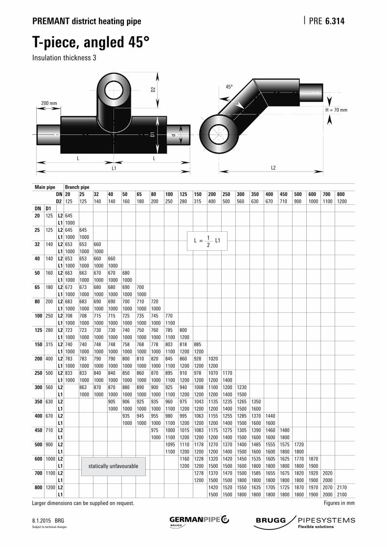
T-piece, angled 45°Insulation thickness 3
L2
200 mm
D2
45°
D1 d
H = 70 mm
L1
LL
Main pipe Branch pipe DN 20 25 32 40 50 65 80 100 125 150 200 250 300 350 400 450 500 600 700 800 D2 125 125 140 140 160 180 200 250 280 315 400 500 560 630 670 710 900 1000 1100 1200 DN D1 20 125 L2 645 L1 1000 25 125 L2 645 645 L1 1000 1000 32 140 L2 653 653 660 L1 1000 1000 1000 40 140 L2 653 653 660 660 L1 1000 1000 1000 1000 50 160 L2 663 663 670 670 680 L1 1000 1000 1000 1000 1000 65 180 L2 673 673 680 680 690 700 L1 1000 1000 1000 1000 1000 1000 80 200 L2 683 683 690 690 700 710 720 L1 1000 1000 1000 1000 1000 1000 1000 100 250 L2 708 708 715 715 725 735 745 770 L1 1000 1000 1000 1000 1000 1000 1000 1100 125 280 L2 723 723 730 730 740 750 760 785 800 L1 1000 1000 1000 1000 1000 1000 1000 1100 1200 150 315 L2 740 740 748 748 758 768 778 803 818 885 L1 1000 1000 1000 1000 1000 1000 1000 1100 1200 1200 200 400 L2 783 783 790 790 800 810 820 845 860 928 1020 L1 1000 1000 1000 1000 1000 1000 1000 1100 1200 1200 1200 250 500 L2 833 833 840 840 850 860 870 895 910 978 1070 1170 L1 1000 1000 1000 1000 1000 1000 1000 1100 1200 1200 1200 1400 300 560 L2 863 870 870 880 890 900 925 940 1008 1100 1200 1230 L1 1000 1000 1000 1000 1000 1000 1100 1200 1200 1200 1400 1500 350 630 L2 905 906 925 935 960 975 1043 1135 1235 1265 1350 L1 1000 1000 1000 1000 1100 1200 1200 1200 1400 1500 1600 400 670 L2 935 945 955 980 995 1063 1155 1255 1285 1370 1440 L1 1000 1000 1000 1100 1200 1200 1200 1400 1500 1600 1600 450 710 L2 975 1000 1015 1083 1175 1275 1305 1390 1460 1480 L1 1000 1100 1200 1200 1200 1400 1500 1600 1600 1800 500 900 L2 1095 1110 1178 1270 1370 1400 1485 1555 1575 1720 L1 1100 1200 1200 1200 1400 1500 1600 1600 1800 1800 600 1000 L2 1160 1228 1320 1420 1450 1535 1605 1625 1770 1870 L1 1200 1200 1500 1500 1600 1800 1800 1800 1800 1900 700 1100 L2 1278 1370 1470 1500 1585 1655 1675 1820 1920 2020 L1 1200 1500 1500 1800 1800 1800 1800 1800 1900 2000 800 1200 L2 1420 1520 1550 1635 1705 1725 1870 1970 2070 2170 L1 1500 1500 1800 1800 1800 1800 1800 1900 2000 2100
Figuresinmm
L = 1 L1 2
Larger dimensions can be supplied on request.
staticallyunfavourable

8.1.2015 BRG
PREMANT district heating pipe PRE
Subject to technical changes
L2
L1
200 mm*
H
d2
d1D1
D2
Parallel T-pieceInsulation thickness 1
6.316
LL
*DN 20 – DN 150: 150 mm
Main pipe Branch pipe DN 20 25 32 40 50 65 80 100 125 150 200 250 300 350 400 450 500 600 700 800 D2 90 90 110 110 125 140 160 200 225 250 315 400 450 500 560 630 710 800 900 1000 L2 450 460 480 480 500 510 510 510 530 570 700 750 850 1000 1000 1100 1200 1300 1500 1700 DN D1 20 90 H 120 L1 1000 25 90 H 120 120 L1 1000 1000 32 110 H 120 120 120 L1 1000 1000 1000 40 110 H 120 120 120 120 L1 1000 1000 1000 1000 50 125 H 120 120 120 120 120 L1 1000 1000 1000 1000 1000 65 140 H 120 120 120 120 120 120 L1 1000 1000 1000 1000 1000 1000 80 160 H 120 120 120 120 120 120 120 L1 1000 1000 1000 1000 1000 1000 1000 100 200 H 120 120 120 120 120 120 120 120 L1 1000 1000 1000 1000 1000 1000 1000 1000 125 225 H 120 120 120 120 120 120 120 120 140 L1 1000 1000 1000 1000 1000 1000 1000 1000 1200 150 250 H 120 120 120 120 120 120 120 120 140 122 L1 1000 1000 1000 1000 1000 1000 1000 1000 1200 1200 200 315 H 120 120 120 120 120 120 120 120 120 164 168 L1 1000 1000 1000 1000 1000 1000 1000 1000 1200 1200 1200 250 400 H 120 120 120 120 120 120 120 120 130 151 197 L1 1000 1000 1000 1000 1000 1000 1000 1200 1200 1200 1400 300 450 H 120 120 120 120 120 120 147 152 197 261 L1 1000 1000 1000 1000 1000 1200 1200 1200 1400 1500 350 500 H 120 120 120 120 120 140 146 188 252 312 L1 1000 1000 1000 1000 1200 1200 1200 1400 1500 1600 400 560 H 120 120 120 140 140 184 247 308 355 L1 1000 1000 1200 1200 1200 1400 1500 1600 1600 450 630 H 120 120 140 180 175 238 298 345 399 L1 1000 1200 1200 1200 1400 1500 1600 1600 1800 500 710 H 120 140 170 180 223 284 331 384 433 L 1200 1200 1200 1400 1500 1600 1600 1800 1800 600 800 H 140 170 215 229 289 336 390 439 546 L1 1200 1500 1500 1600 1800 1800 1800 1800 1900 700 900 H 170 215 280 290 337 391 440 572 688 L1 1500 1500 1800 1800 1800 1800 1800 1900 2000 800 1000 H 170 215 280 291 338 392 440 573 689 816 L1 1500 1500 1800 1800 1800 1800 1800 1900 2000 2100
Figuresinmm
L = 1 L1 2
Larger dimensions can be supplied on request.
staticallyunfavourable
8.1.2015 BRG
PREMANT district heating pipe PRE
Subject to technical changes
6.317
L2
L1
200 mm*
H
d2
d1D1
D2
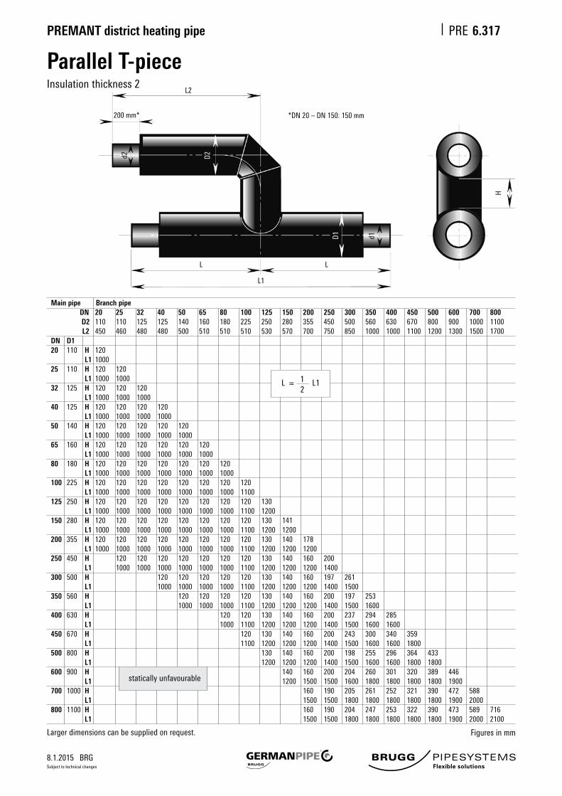
Parallel T-pieceInsulation thickness 2
LL
Main pipe Branch pipe DN 20 25 32 40 50 65 80 100 125 150 200 250 300 350 400 450 500 600 700 800 D2 110 110 125 125 140 160 180 225 250 280 355 450 500 560 630 670 800 900 1000 1100 L2 450 460 480 480 500 510 510 510 530 570 700 750 850 1000 1000 1100 1200 1300 1500 1700 DN D1 20 110 H 120 L1 1000 25 110 H 120 120 L1 1000 1000 32 125 H 120 120 120 L1 1000 1000 1000 40 125 H 120 120 120 120 L1 1000 1000 1000 1000 50 140 H 120 120 120 120 120 L1 1000 1000 1000 1000 1000 65 160 H 120 120 120 120 120 120 L1 1000 1000 1000 1000 1000 1000 80 180 H 120 120 120 120 120 120 120 L1 1000 1000 1000 1000 1000 1000 1000 100 225 H 120 120 120 120 120 120 120 120 L1 1000 1000 1000 1000 1000 1000 1000 1100 125 250 H 120 120 120 120 120 120 120 120 130 L1 1000 1000 1000 1000 1000 1000 1000 1100 1200 150 280 H 120 120 120 120 120 120 120 120 130 141 L1 1000 1000 1000 1000 1000 1000 1000 1100 1200 1200 200 355 H 120 120 120 120 120 120 120 120 130 140 178 L1 1000 1000 1000 1000 1000 1000 1000 1100 1200 1200 1200 250 450 H 120 120 120 120 120 120 120 130 140 160 200 L1 1000 1000 1000 1000 1000 1000 1100 1200 1200 1200 1400 300 500 H 120 120 120 120 120 130 140 160 197 261 L1 1000 1000 1000 1000 1100 1200 1200 1200 1400 1500 350 560 H 120 120 120 120 130 140 160 200 197 253 L1 1000 1000 1000 1100 1200 1200 1200 1400 1500 1600 400 630 H 120 120 130 140 160 200 237 294 285 L1 1000 1100 1200 1200 1200 1400 1500 1600 1600 450 670 H 120 130 140 160 200 243 300 340 359 L1 1100 1200 1200 1200 1400 1500 1600 1600 1800 500 800 H 130 140 160 200 198 255 296 364 433 L1 1200 1200 1200 1400 1500 1600 1600 1800 1800 600 900 H 140 160 200 204 260 301 320 389 446 L1 1200 1500 1500 1600 1800 1800 1800 1800 1900 700 1000 H 160 190 205 261 252 321 390 472 588 L1 1500 1500 1800 1800 1800 1800 1800 1900 2000 800 1100 H 160 190 204 247 253 322 390 473 589 716 L1 1500 1500 1800 1800 1800 1800 1800 1900 2000 2100
Figuresinmm
L = 1 L1 2
Larger dimensions can be supplied on request.
staticallyunfavourable
*DN 20 – DN 150: 150 mm

8.1.2015 BRG
PREMANT district heating pipe PRE
Subject to technical changes
6.318
L2
L1
200 mm*
H
d2
d1D1
D2
Parallel T-pieceInsulation thickness 3
LL
*DN 20 – DN 150: 150 mm
Larger dimensions can be supplied on request.
Main pipe Branch pipe DN 20 25 32 40 50 65 80 100 125 150 200 250 300 350 400 450 500 600 700 800 D2 125 125 140 140 160 180 200 250 280 315 400 500 560 630 670 710 900 1000 1100 1200 L2 450 460 480 480 500 510 510 510 530 570 700 750 850 1000 1000 1100 1200 1300 1500 1700 DN D1 20 125 H 120 L1 1000 25 125 H 120 120 L1 1000 1000 32 140 H 120 120 120 L1 1000 1000 1000 40 140 H 120 120 120 120 L1 1000 1000 1000 1000 50 160 H 120 120 120 120 120 L1 1000 1000 1000 1000 1000 65 180 H 120 120 120 120 120 120 L1 1000 1000 1000 1000 1000 1000 80 200 H 120 120 120 120 120 120 120 L1 1000 1000 1000 1000 1000 1000 1000 100 250 H 120 120 120 120 120 120 120 130 L1 1000 1000 1000 1000 1000 1000 1000 1000 125 280 H 120 120 120 120 120 120 120 130 130 L1 1000 1000 1000 1000 1000 1000 1000 1000 1200 150 315 H 120 120 120 120 120 120 120 130 130 130 L1 1000 1000 1000 1000 1000 1000 1000 1000 1200 1200 200 400 H 120 120 120 120 120 120 120 130 130 130 133 L1 1000 1000 1000 1000 1000 1000 1000 1000 1200 1200 1200 250 500 H 120 120 120 120 120 120 130 130 130 130 147 L1 1000 1000 1000 1000 1000 1000 1000 1200 1200 1200 1400 300 560 H 120 120 120 120 130 130 130 130 142 151 L1 1000 1000 1000 1000 1000 1200 1200 1200 1400 1500 350 630 H 120 120 120 130 130 130 130 130 132 183 L1 1000 1000 1000 1000 1200 1200 1200 1400 1500 1600 400 670 H 120 130 130 130 130 130 137 189 245 L1 1000 1000 1200 1200 1200 1400 1500 1600 1600 450 710 H 130 130 130 130 130 143 194 250 319 L1 1000 1200 1200 1200 1400 1500 1600 1600 1800 500 900 H 130 130 130 130 173 175 231 299 343 L1 1200 1200 1200 1400 1500 1600 1600 1800 1800 600 1000 H 130 130 130 140 175 181 250 294 346 L1 1200 1500 1500 1600 1800 1800 1800 1800 1900 700 1100 H 130 130 140 176 182 251 295 372 488 L1 1500 1500 1800 1800 1800 1800 1800 1900 2000 800 1200 H 130 130 140 177 183 252 295 373 489 616 L1 1500 1500 1800 1800 1800 1800 1800 1900 2000 2100
Figuresinmm
L = 1 L1 2
staticallyunfavourable

8.1.2015 BRG
PREMANT district heating pipe PRE
Subject to technical changes
Fixed pointThermallyandelectricallyseparated(allinsulations)
6.320
Fordimensionsoftheconcreteblock(foundationdimensions)andconcretequality,seesheetPRE6.515.Wallsealingrings(PRE6.355)hastobeorderedseparately.Asanoptionnonthermalandelectricallyseparatedfixingpointsareavailableonrequest.
Main pipe Ancor flanges
Nominal Steel pipe Insulation Insulation Insulation Nominal Insulation Insulation Insulation
width thickness 1 thickness 2 thickness 3 length thickness 1 thickness 2 thickness 3
DN d D D D L a/b x s a/b x s a/b x s
mm mm mm mm mm mm mm mm
20 26.9 90 110 125 2000 200 x 15 200 x 15 200 x 15
25 33.7 90 110 125 2000 200 x 15 200 x 15 200 x 15
32 42.4 110 125 140 2000 200 x 15 200 x 15 200 x 15
40 48.3 110 125 140 2000 200 x 15 200 x 15 200 x 15
50 60.3 125 140 160 2000 250 x 20 250 x 20 250 x 20
65 76.1 140 160 180 2000 250 x 20 250 x 20 250 x 20
80 88.9 160 180 200 2000 250 x 20 250 x 20 250 x 20
100 114.3 200 225 250 2000 330 x 25 330 x 25 330 x 25
125 139.7 225 250 280 2000 330 x 25 330 x 25 330 x 25
150 168.3 250 280 315 2000 380 x 25 380 x 25 380 x 25
200 219.1 315 355 400 2000 500 x 25 500 x 25 500 x 25
250 273.0 400 450 500 2000 600 x 30 600 x 30 600 x 30
300 323.9 450 500 560 2000 700 x 30 700 x 30 700 x 30
350 355.6 500 560 630 2000 700 x 30 700 x 30 700 x 30
400 406.4 560 630 670 2000 800 x 30 800 x 30 800 x 30
450 457.2 630 670 710 2000 800 x 30 800 x 30 900 x 30
500 508.0 710 800 900 2000 900 x 30 900 x 30 1000 x 35
600 610.0 800 900 1000 2000 1000 x 35 1000 x 35 1100 x 40
s
Fr
a/b
d D
L
Figuresinmm
200 mm
Fr=Frictionforce
8.1.2015 BRG
PREMANT district heating pipe PRE
Subject to technical changes
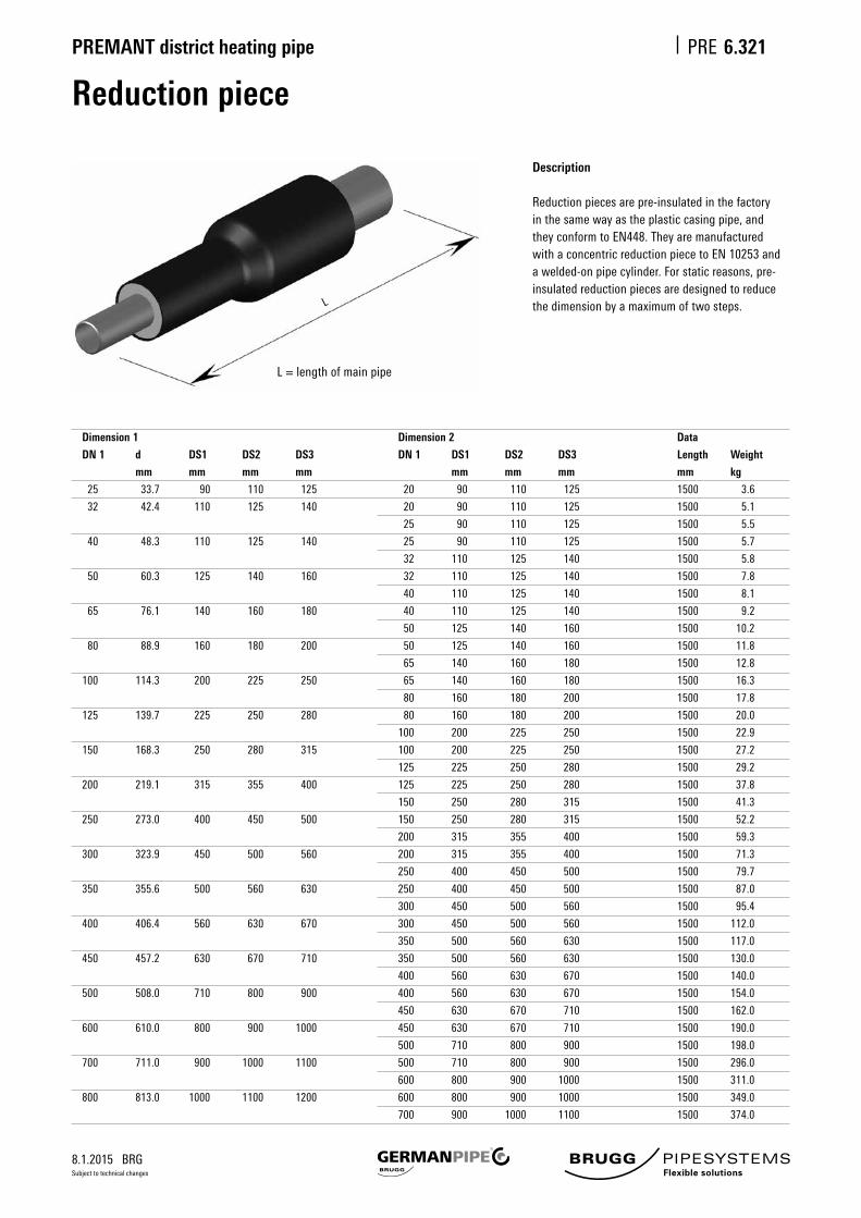
Reduction piece
6.321
L = length of main pipe
Description
Reductionpiecesarepre-insulatedinthefactoryinthesamewayastheplasticcasingpipe,andtheyconformtoEN448.Theyaremanufacturedwith a concentric reduction piece to EN 10253 and awelded-onpipecylinder.Forstaticreasons,pre-insulated reduction pieces are designed to reduce thedimensionbyamaximumoftwosteps.
Dimension 1
DN 1
25
32
40
50
65
80
100
125
150
200
250
300
350
400
450
500
600
700
800
d
mm
33.7
42.4
48.3
60.3
76.1
88.9
114.3
139.7
168.3
219.1
273.0
323.9
355.6
406.4
457.2
508.0
610.0
711.0
813.0
DS1
mm
90
110
110
125
140
160
200
225
250
315
400
450
500
560
630
710
800
900
1000
DS2
mm
110
125
125
140
160
180
225
250
280
355
450
500
560
630
670
800
900
1000
1100
DS3
mm
125
140
140
160
180
200
250
280
315
400
500
560
630
670
710
900
1000
1100
1200
Dimension 2
DN 1
20
20
25
25
32
32
40
40
50
50
65
65
80
80
100
100
125
125
150
150
200
200
250
250
300
300
350
350
400
400
450
450
500
500
600
600
700
DS1
mm
90
90
90
90
110
110
110
110
125
125
140
140
160
160
200
200
225
225
250
250
315
315
400
400
450
450
500
500
560
560
630
630
710
710
800
800
900
DS2
mm
110
110
110
110
125
125
125
125
140
140
160
160
180
180
225
225
250
250
280
280
355
355
450
450
500
500
560
560
630
630
670
670
800
800
900
900
1000
DS3
mm
125
125
125
125
140
140
140
140
160
160
180
180
200
200
250
250
280
280
315
315
400
400
500
500
560
560
630
630
670
670
710
710
900
900
1000
1000
1100
Data
Length
mm
1500
1500
1500
1500
1500
1500
1500
1500
1500
1500
1500
1500
1500
1500
1500
1500
1500
1500
1500
1500
1500
1500
1500
1500
1500
1500
1500
1500
1500
1500
1500
1500
1500
1500
1500
1500
1500
Weight
kg
3.6
5.1
5.5
5.7
5.8
7.8
8.1
9.2
10.2
11.8
12.8
16.3
17.8
20.0
22.9
27.2
29.2
37.8
41.3
52.2
59.3
71.3
79.7
87.0
95.4
112.0
117.0
130.0
140.0
154.0
162.0
190.0
198.0
296.0
311.0
349.0
374.0
L

8.1.2015 BRG
PREMANT district heating pipe PRE
Subject to technical changes
Vent
6.322
h = height of vent from axis of main pipeL = length of main pipe
Description
Ventsarepre-insulatedinthefactoryinthesamewayastheplasticcasingpipe,andtheyconformtoEN448.Theinsula-tionprotectiononthefrontoftheventnozzleisprovidedbyaheat-shrunkendcap.ThebranchismadewithaT-piecetoEN10253andwelded-onpipecylinders,orbyextrudingthebasepipe.
The vent ball valve is manufactured from stainless steel 1.4301, and is supplied complete with plugs. The inner thread corresponds to the nominal width of the vent. All the exposed parts of the valve are made of stainless steel. The nozzle height(h)andthenominalwidthcanbechangedatthecustomer'srequest.
L
Main pipe
DN
25
32
40
50
65
80
100
125
150
200
250
300
350
400
450
500
600
700
800
d
mm
33.7
42.4
48.3
60.3
76.1
88.9
114.3
139.7
168.3
219.1
273.0
323.9
355.6
406.4
457.2
508.0
610.0
711.0
813.0
DS1
mm
90
110
110
125
140
160
200
225
250
315
400
450
500
560
630
710
800
900
1000
DS2
mm
110
125
125
140
160
180
225
250
280
355
450
500
560
630
670
800
900
1000
1100
DS3
mm
125
140
140
160
180
200
250
280
315
400
500
560
630
670
710
900
1000
1100
1200
Vent
DN
25
25
25
25
32
32
32
40
40
40
50
50
50
50
50
50
50
50
50
D
mm
90
90
90
90
110
110
110
110
110
110
125
125
125
125
125
125
125
125
125
h
mm
650
650
660
660
670
680
690
700
720
740
840
860
880
900
930
1000
1050
1100
1150
L
mm
1000
1000
1000
1000
1000
1000
1000
1000
1000
1000
1000
1000
1000
1000
1000
1000
1200
1200
1200
Weight
DS1
kg
5.3
6.6
7.1
8.2
10.6
11.9
15.6
18.9
23.5
32.6
47.5
59.8
66.5
82.9
94.4
107.8
139.6
176.9
216.8
DS2
kg
5.6
6.8
7.3
8.4
11.0
12.3
16.3
19.7
24.5
34.4
50.2
62.9
70.7
88.2
97.9
116.6
149.1
187.2
228.3
DS3
kg
5.8
7.1
7.5
8.7
11.3
12.8
17.0
20.7
25.9
36.7
53.3
67.1
76.0
91.7
101.4
126.0
159.4
198.7
241.3
h

8.1.2015 BRG
PREMANT district heating pipe PRE
Subject to technical changes
Drainer
6.323
h = height of drainer from axis of main pipeL = length of main pipe
Theendcapontheventbranchhastobeorderedseparately.
Description
Theendcapontheventbranchhastobeorderedseparately.Drainersarepre-insulatedinthefactoryinthesamewayastheplasticcasingpipe,andtheyconformtoEN448.ThebranchismadewithaT-piecetoEN10253andwelded-onpipecylinders,orbyextrudingthebasepipe.
Thenozzleheight(h)andthenominalwidthcanalsobeproducedtothecustomer'srequirements.Flanges,reliefvalvesand ball valves can also be used as closures for the nozzle.
L
Main pipe
DN
25
32
40
50
65
80
100
125
150
200
250
300
350
400
450
500
600
700
800
d
mm
33.7
42.4
48.3
60.3
76.1
88.9
114.3
139.7
168.3
219.1
273.0
323.9
355.6
406.4
457.2
508.0
610.0
711.0
813.0
DS1
mm
90
110
110
125
140
160
200
225
250
315
400
450
500
560
630
710
800
900
1000
DS2
mm
110
125
125
140
160
180
225
250
280
355
450
500
560
630
670
800
900
1000
1100
DS3
mm
125
140
140
160
180
200
250
280
315
400
500
560
630
670
710
900
1000
1100
1200
Drainer
DN
25
25
25
32
32
40
40
50
50
80
80
80
100
100
100
100
100
100
100
D
mm
90
90
90
110
110
110
110
125
125
160
160
160
200
200
200
200
200
200
200
h
mm
660
660
660
670
680
690
710
730
740
780
830
850
880
920
940
1000
1050
1100
1150
L
mm
1000
1000
1000
1000
1000
1000
1000
1000
1000
1000
1000
1000
1000
1000
1000
1000
1200
1200
1200
Weight
DS1
kg
4.7
6.0
6.5
8.7
10.1
11.7
15.5
19.1
23.7
35.4
48.1
60.6
77.8
96.6
110.0
125.0
176.0
222.0
271.0
DS2
kg
5.0
6.2
6.7
8.9
10.4
12.1
16.2
19.9
24.8
37.2
50.8
63.7
82.7
103.0
114.0
136.0
189.0
236.0
286.0
DS3
kg
5.2
6.5
6.9
9.3
10.8
12.6
17.0
20.9
26.1
39.4
53.9
67.9
89.0
107.0
118.0
146.0
203.0
251.0
304.0
h

8.1.2015 BRG
PREMANT district heating pipe PRE
Subject to technical changes
Fittings installed in the groundDescription, installation and operating instructions
6.325
GeneralWeonlyprovidesystematicheatinsulationforballvalvesiftheyaresuitable for direct installation in the ground, with or without pre-stressing, i.e.:
A.iftheyfulfiltherequirementsacc.EN488B. if there are no screwed connectors in the insulated area.
Range of applications• Up to 160 °C / 16 bar or 140 °C / 25 bar• Processed,demineralized,cleantapwaterwithlowoxygencontent• not suitable for installation in the area of bends and expansion limbs
Material• Housing made of steel, forged and welded.• Ball in stainless steel• Switching spindle in stainless steel• SealsinreinforcedTeflon• Ball seal, spring-supported• Spindle seal, multiple• Monitoring wire, foamed in• Heat insulation made of rigid PUR foam• HDPE casing
Delivery and storage• Ball valves in open position• Protective caps on both pipe ends
Assembly / installation• Onlyweldintheballvalvesintheopenposition,andprotectthe housing against overheating while doing so• Install expansion pads in the area of the dome, as per the instructions• Payspecialattentiontoensurethatthedomehassufficientfreedom of movement• The upper uninsulated section of the spindle must not stand in the groundwater/other water• Thefirstswitchingoperationmustonlytakeplaceafterthepipehas beenflushedthrough(openthegatevalvefirst)• Ifthereisariskoffrost,uncoveredfittingsmustbecompletelyemptied• Thoroughlygreasethesteelpartsonthedome• If there is a provisional pipe end, the free pipe end must be welded shut
Position indicator• Milled-in notch on switch spindle square, and pointer
Activation• Closebyturningtotheright(clockwise)asfarasthestop (90°forballvalve)
Operation• Matching socket wrenches must be used for switching• Plug-on gears with matching receiver components can be supplied forballvalves(ourrecommendationforDN200andabove)• Donotapplyforcetotheswitchingshaft• Do not overtighten the end stops• Intermediate positions are not allowed for ball valves due to the possbilityofwearontheballseals• Theprocessedtapwatermustnotcontainanysolidparticles becausetheycoulddamagethesealingsurfaces
Maintenance• Periodicallycleanthesteelpartsonthedomeandgreasethem thoroughly• SwitchbetweenOPENandCLOSEDseveraltimes,atleastevery 3 months, until smooth running is achieved• Check the freedom of movement of the dome• Check the groundwater level and condition
Important
It is essential to follow the above instructions. We and/or the fittings manufacturer cannot provide any warranty for damage due to incorrect installation, handling and maintenance.
8.1.2015 BRG
PREMANT district heating pipe PRE
Subject to technical changes
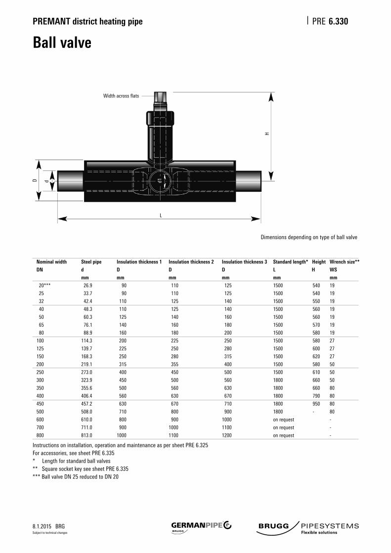
Ball valve
6.330
Nominal width Steel pipe Insulation thickness 1 Insulation thickness 2 Insulation thickness 3 Standard length* Height Wrench size**
DN d D D D L H WS
mm mm mm mm mm mm
20*** 26.9 90 110 125 1500 540 19
25 33.7 90 110 125 1500 540 19
32 42.4 110 125 140 1500 550 19
40 48.3 110 125 140 1500 560 19
50 60.3 125 140 160 1500 560 19
65 76.1 140 160 180 1500 570 19
80 88.9 160 180 200 1500 580 19
100 114.3 200 225 250 1500 580 27
125 139.7 225 250 280 1500 600 27
150 168.3 250 280 315 1500 620 27
200 219.1 315 355 400 1500 580 50
250 273.0 400 450 500 1500 610 50
300 323.9 450 500 560 1800 660 50
350 355.6 500 560 630 1800 660 80
400 406.4 560 630 670 1800 790 80
450 457.2 630 670 710 1800 950 80
500 508.0 710 800 900 1800 - 80
600 610.0 800 900 1000 on request -
700 711.0 900 1000 1100 on request -
800 813.0 1000 1100 1200 on request -
Instructions on installation, operation and maintenance as per sheet PRE 6.325Foraccessories,seesheetPRE6.335* Length for standard ball valves**SquaresocketkeyseesheetPRE6.335*** Ball valve DN 25 reduced to DN 20
Width across flats
L
H
D d d1
Dimensionsdependingontypeofballvalve

8.1.2015 BRG
PREMANT district heating pipe PRE
Subject to technical changes
Ball valve with 2 vents
6.332
Main pipe Wrench size Draining/venting valve
Nominal Steel Insulation Insulation Insulation Nominal Nominal
width pipe thickness 1 thickness 2 thickness 3 length width
DN d D D D L WS h DN Da a h
mm mm mm mm mm mm mm mm mm mm
25 33.7 90 110 125 1500 19 540 25 90 320 350
32 42.4 110 125 140 1500 19 550 25 90 320 350
40 48.3 110 125 140 1500 19 560 25 90 320 360
50 60.3 125 140 160 1500 19 560 25 90 320 360
65 76.1 140 160 180 1500 19 570 32 110 320 370
80 88.9 160 180 200 1500 19 580 32 110 320 380
100 114.3 200 225 250 1500 27 580 32 110 320 390
125 139.7 225 250 280 1500 27 600 40 110 320 500
150 168.3 250 280 315 1500 27 620 40 110 320 510
200 219.1 315 355 400 1500 50 580 40 110 320 540
250 273.0 400 450 500 2000 50 610 50 125 400 580
300 323.9 450 500 560 2000 50 660 50 125 500 610
Thedimensioningoftheventingfittingcanbefreelyselected.
Instructions on installation, operation and maintenance as per sheet PRE 6.325Foraccessories,seesheetPRE6.335
a
Da
L
h
D d
Da
a
WS
150
h = high of vent
≥200

8.1.2015 BRG
PREMANT district heating pipe PRE
Subject to technical changes
Ball valve with 1 vents
6.333
Main pipe Wrench size Draining/venting valve
Nominal Steel Insulation Insulation Insulation Nominal Nominal
width pipe thickness 1 thickness 2 thickness 3 length width
DN d D D D L WS h DN Da a h
mm mm mm mm mm mm mm mm mm mm
25 33.7 90 110 125 1500 19 540 25 90 320 350
32 42.4 110 125 140 1500 19 550 25 90 320 350
40 48.3 110 125 140 1500 19 560 25 90 320 360
50 60.3 125 140 160 1500 19 560 25 90 320 360
65 76.1 140 160 180 1500 19 570 32 110 320 370
80 88.9 160 180 200 1500 19 580 32 110 320 380
100 114.3 200 225 250 1500 27 580 32 110 320 390
125 139.7 225 250 280 1500 27 600 40 110 320 500
150 168.3 250 280 315 1500 27 620 40 110 320 510
200 219.1 315 355 400 1500 50 580 40 110 320 540
250 273.0 400 450 500 1750 50 610 50 125 400 580
300 323.9 450 500 560 1810 50 660 50 125 500 610
Thedimensioningoftheventingfittingcanbefreelyselected.
Instructions on installation, operation and maintenance as per sheet PRE 6.325Foraccessories,seesheetPRE6.335
a
Da
h
D d
L
SW
150

8.1.2015 BRG
PREMANT district heating pipe PRE
Subject to technical changes
Ball valve for installation in the groundInstallation diagram
6.334
Protectivepipesforthespindlemustbeprovidedbythecustomerorothers;seesheetPRE6.520-6.525.
DPE
DDOM
Ball valve DDOM* DPE*
DN
mm mm
20 ... 80 110 140
100 125 160
125 ... 200 140 180
250 200 225
300 200 225
* for standard ball valves
Deliverylength: 1.0/1.5/2.0mOptionsofsupply: –withoutsealingcap(standard) – with sealing cap
PE protective pipe
Road cap no. 2
DIN 3582 in cast iron
Secured surface
Sealing cap with seal
Concrete crown
Concrete plate
PE-HD protective pipe
Spindle extension
PREMANT ball valve
Shrink-on collar
Expansion pad

8.1.2015 BRG
PREMANT district heating pipe PRE
Subject to technical changes
6.335
Gearcanbesuppliedonrequest(forDN200ormore,agearisrecommended)
Accessories – shut-off fittingBall valve
Square adapter
Square, 27/32Square, 27/32
Hexagon; Width acrossflats27
Hexagon; Width acrossflats19
Ball valve
Square wrench, 27/32
Square27/32
Ø24
1100
Figuresinmm
for ball valveDN 100 - DN 150
for ball valveDN 25 - DN 80

8.1.2015 BRG
PREMANT district heating pipe PRE
Subject to technical changes
1. PE shrink sleeve, non-cross-linked
The non-cross-linked shrink sleeve consists of a heat-shrunk PE sleeve pipe and the following accessories:
- Shrink-on collars-Permanentlyelasticsealingstrip,butylrubber- Venting plug- Welded-in PE plug
The shrink sleeves are pushed onto the casing pipe when the pipe is being laid, before the medium pipe weld seams are made. The connec-tionpointsarethenfittedwithadditionalinsulationbytrainedfittingstaffwhohavebeentestedasperAGFWWorksheetFW603.
This produces a watertight, non-positive connection between the casing pipe and the sleeve. The sealing strip and the shrink-on collars are used to double-seal the sleeve joint. Technical requirements as per EN489,AGFWWorksheetFW401,parts6,14,16and17.
2. Shrink sleeve made of cross-linked PE
Thecross-linkedshrinksleeveconsistsofmolecularcross-linkedpoly-ethylene,soonlylimitedweldingispossible.Theveryhighshrinkagecapacityofthismaterialcombinedwiththesealingstripinsertedbetweenthecasingpipeandthesleeveproduceaverystrongnon-positive connection.
Becausethistypeofsleevecanwithstandhighmechanicalloads,itisespeciallysuitableforplasticcasingpipesectionsthataresubjecttohigherstresses(e.g.frequentloadalternation,pipeslaidinthegroundwaterzone).
Sleeve jointShrink sleeve, non-cross-linked/cross-linked
6.340
Nominal width: 90 ... 1200Length: 700, 1000, 1400 mm
Nominal width: 90 ... 1200Length: 700 mm

8.1.2015 BRG
PREMANT district heating pipe PRE
Subject to technical changes
3. Shrink-on reduction sleeves
Forreasonsrelatedtostatics,shrink-onreductionsleevestoinsulatesteelreductionjointsthatareweldedinbythepipelayer(providedbythecustomerorothers)aredesignedtoreducethedimensionbya maximum of three steps. Their structure corresponds to that of the non-cross-linkedPEshrinksleeve,andtheymustbepushedontotheouter casing before the medium pipe is welded.
The non-cross-linked reduction shrink sleeve consists of a heat-shrunk PE sleeve pipe and the following accessories:
- Shrink-on collars-Permanentlyelasticsealingstrip,butylrubber- Venting plug- Welded-in PE plug
4. Fitting sleeve
Fittingsleevesmadeofnon-cross-linkedPEareusedwhenitisnotpossible to push the joint sleeves on due to shortage of space. Thefittingsleeveisseparatedintheaxialdirectionanditcanthenbe moved into position over the points where the pipes are connected. This separation point is welded to guarantee the tightness of the sleeve.
5. Shrink-on end sleeve
The shrink-on end sleeve is used to insulate pipe closures in the ground and in buildings or shafts. It has the same structure as a non-cross-linked PE shrink-on sleeve but is sealed on one side with a PE end cover.
6.342
Sleeve jointReductionsleeves,fittingsleevesandshrink-onendsleeves
Nominal width: 90 ... 1200Length: 700, 1000, 1400 mm
Nominal width: 90 ... 1200Length if end is:dished end: 700 mmone time ball valve: 1400 mm
Nom. width Reduction sleeve Length
D D D D L
mm mm mm mm mm
110 90 700
125 110 90 700
140 125 110 90 700
160 140 125 110 700
180 160 140 125 700
200 180 160 140 900
225 200 180 160 900
250 225 200 180 900
280 250 225 200 900
315 280 250 225 900
355 315 280 250 900
Nom. width Reduction sleeve Length
D D D D L
mm mm mm mm mm
400 355 315 280 900
450 400 355 315 900
500 450 400 355 1200
560 500 450 400 1200
630 560 500 450 1200
670 630 560 500 1200
710 670 630 560 1200
800 710 670 630 1400
900 800 710 670 1400
1000 900 800 710 1400
1100 1000 900 800 1400

8.1.2015 BRG
PREMANT district heating pipe PRE
Subject to technical changes
6.345
Brugg VISUCON
BruggVISUCONisaconnectiontechnologywhichisfundamentallydifferentfromtheprocessingofothersleevesystems.VISUCONmakespossiblevisualinspectionofthepolyurethanefoam.Thismeansitisnotnecessarytodestroythesleeveorthefoam.
With the VISUCON connection sleeve, the annular space for the external foaming process is not limitedbyapolyethylenesleeve,butbyreusableformingshells.Withthistechnology,theexternalsealingconnectionisnotmadeuntilafterthefoamingprocessiscomplete.Theresultandqualityofthepolyurethanefoamcanbereliablytestedforeverysleeve.
Sleevesystemparts:
- Polyurethanefoam,madeofliquidcomponentspolyolandisocyanate(cf.PRE6.410)- Sealingshrinkfilm- Sealing tape- VISUCON sleeve bodies made of integrated shrinkable HDPE
AcylindricalVISUCONshellisusedforinstallation,whichisthenremovedafterthepolyurethanefoamhardens.Thetwosealingsystemsaretheninstalled.Duetothesystemdesign,nofoamingholesarenecessary,meaningtheplugweldingprocesscanalsobeomitted.TheVISUCONsleevebodyshrinksacrossitsentirelengthduringinstallation,wherebythesleeveareadoesnotexpand.Thisunchangingpipediametercanbeadvantageousduringpipeinstallationinemptytubesorwhen driving over cable links.
Nominal size 160...710 mm Length: 780 mm
BruggVISUCONisonlyavailableasastraightconnectionsleeve.Non-integratedshrinksleevesshould be used for reducing sockets and stop ends.
Polyurethanehalfshells
TheVISUCONconnectionsleevecanalsobeusedtogetherwiththeprefabricatedpolyurethanehalfshells.Inthiscase,formingVISUCONshellsarenotnecessary.Theremaininginstallationisidentical.
Welding-Foaming-Sealing

8.1.2015 BRG
PREMANT district heating pipe PRE
Subject to technical changes
6.350
EWELCON electro-welding jointSystemdescription
TheEWELCONelectro-weldingjointistheprotectednameforaweldingjointfromBRUGGPipeSystemstoproducejointswhichtransmitforce,andarewatertightandgastight,forplasticpipes-mainlyPE-HDcasingpipes(pre-insulatedplasticcasingpipes(KMR))inthedistrictheatingsector.
TheEWELCONelectro-weldingjointisafullyprefabricatedHD-PEplatewhichisonlyplaced('wrapped')aroundthetwoendsoftheplasticcasingpipeimmediatelypriortowelding.Thissimplifiesthefittingprocedrureandplaysakeypartinthehighandconstantqualityofthejoint,evenindifficultandconfinedinstallationlocations.Theweldseamareacaneasilybecleanedanddried.
ThesepropertiesmaketheEWELCONsystemespeciallysuitableforrepairsandrefurbishmentsonexistingpipes.
The'inside'ofthePE-HDplateintheEWELCONelectro-weldingjointisfittedwithathermalconductorandatempera-ture sensor. The thermal conductor, a meanderform copper wire, forms a heating spiral with a width of approx. 27 mm. Thepositionoftheheatingspiralisselectedsothatwhentheplateisplacedaroundit,itcompletelysurroundstheinte-riorofthejoint.Duringtheweldingprocess,thepipeandplatematerialsareplastifiedalongtheheatingspiral,andarehomogeneouslymixedduetothehighexpansivepressureofthemelts.Afterthemeltscooldown,theinteriorissealedbyaweldseamwithawidthofapprox.30mm.
Together with the contact pressure for the weld surfaces, the weld bath temperature is the most important requirement forplasticweldseamsofhighquality.
ThisfactisconsistentlyimplementedintheEWELCONsystem.
Therequiredcontactpressureisreliablyappliedbytheclampingtoolspeciallydevelopedforthispurpose.
Theweldingprocessisregulatedbyamicroprocessor-controlledweldingappliance.Thetemperaturesoftheweldbathand the thermal conductor are monitored and stored throughout the entire welding process. This method ensures that the weldbathtemperatureislargelyindependentofdisruptiveexternalinfluences(suchastheweather)andthuscompara-ble from one welding operation to the next.
Everyjointproducedissubjectedtoathoroughvisualinspectionandatightnesstest,afterwhichitisfoamedandthefillingandventingboresaresealedwithweldplugs.

8.1.2015 BRG
PREMANT district heating pipe PRE
Subject to technical changes
6.351
Casing pipe Ø
D
mm
90
110
125
140
160
180
200a
225
250
280
315
355
400
450
500
560
630
710
800
900
1000
Width
B1
mm
700 or 850
700 or 850
700 or 850
700 or 850
700 or 850
700 or 850
700 or 850
700 or 850
700 or 850
700 or 850
700 or 850
700 or 850
700 or 850
700 or 850
700 or 850
700 or 850
700 or 850
700 or 850
700 or 850
700 or 850
700 or 850
Length
L
mm
450
515
560
610
675
740
805
885
950
1050
1160
1290
1440
1600
1830
2020
2250
2580
2870
3190
3510
Thickness
s
mm
4
4
4
4
4
4
4
4
4
4
4
4
4
4
6
6
6
8
8
8
8
Weight
B 700
kg
1.2
1.3
1.5
1.7
1.9
2.1
2.3
2.4
2.5
2.7
3.0
3.3
3.7
4.2
7.0
7.7
8.7
13.2
14.7
16.5
18.0
B 850
kg
1.5
1.6
1.8
2.1
2.3
2.6
2.8
2.9
3.0
3.2
3.6
4.0
4.5
5.0
8.5
9.5
10.5
16.0
17.8
20.0
22.0
Packaging unit
B 700
Piece
18
18
18
16
16
16
15
15
20/40/80
20/40/80
20/40/80
20/40/80
20/40/80
20/40/80
20/40
20/40
20/40
20
20
20
10/20
B 850
Piece
18
18
18
16
16
16
15
15
20/40/80
20/40/80
20/40/80
20/40/80
20/40/80
20/40/80
20/40
20/40
20/40
20
20
20
10/20
B1
L
EWELCON electro-welding jointTechnical data
Material:PE80-DINEN32162(PE-HD)
Furtherdimensionsonrequest.SleevesuptoØ225arepre-rolledfordeliverySleeve widths: Standard width: B = 700; repair width: B = 850
Heating spiral
connection wire
Heating spiral Temperature sensor
Heating spiral
connection wire
Plattendicke: s

8.1.2015 BRG
PREMANT district heating pipe PRE
Subject to technical changes
6.352
EWELCON-SSystemdescription
TheEWELCON-SElectro-WeldingJointisamemberofthe"EWELCONfamily".Itistheidealmatchforourtried-and-tested EWELCON welding joint for the smaller dimension range.
The shrink-on sleeve and the prefabricated heating elements for the EWELCON-S electro-welding joint are delivered in separatepackagingunits.Theshrink-onsleeve,whichisfittedwithsolarprotectionfoil,ispushedontothecasingpipebeforeweldingtheinnerpipes.Theheatingelementsaredeliveredinhandypackagingunitswhichareprotectedagainstcontaminationasappropriateforuseonconstructionsites.Theheatingelementsareonlyplacedaroundthetwoendsoftheplasticcasingpipeimmediatelybeforewelding.Theweldseamareacaneasilybecleanedanddried.Thisplaysakeypartinthehighandconstantqualityofthejoint,evenindifficultandconfinedinstallationlocations.ThesepropertiesmaketheEWELCON-Ssystemparticularlysuitablefornewinstallations.RepairsandrefurbishmentsonexistingpipesarecarriedoutwiththeEWELCONweldingjointusingthewraparoundmethod.Forqualityreasons,theinstallationisonlycarriedoutbyfitterswhohaveacquiredthenecessaryqualificationsafterthoroughtrainingfromourtrainingstaff.
The shrink-on sleeve in the EWELCON electro-welding joint consists of bimodal PE-HD. This ensures optimal long-term properties. The thermal conductor, a meanderform copper wire, is embedded in a PE-HD carrier strip. Each heating elementsetisfittedwithatemperaturesensor.Theheatingelementsarefixedontothepreparedcasingpipeends;theyadapt to the component tolerances. The special design in the area of the connecting ends ensures constant welding conditions over the entire pipe circumference.
Followingtheusualon-sitemethod,theshrinksleeveisshrunkdownontothecasingpipeendswithagentlepropanegasflame;theheatingelementsareoptimallychamberedasthisisdone.Togetherwiththecontactpressurefortheweldsurfaces,theweldbathtemperatureisthemostimportantrequirementforplasticweldseamsofhighquality.ThisfactisconsistentlyimplementedintheEWELCON-Ssystem.Therequiredcontactpressureisreliablyappliedbytheclampingtoolspeciallydevelopedforthispurpose.
Theweldingprocessisregulatedbyamicroprocessor-controlledweldingappliance.Thetemperaturesoftheweldbathand the thermal conductor are monitored and stored throughout the entire welding process. This method ensures that theweldbathtemperatureislargelyindependentofdisruptiveexternalinfluences(suchastheweather)andthuscomparable from one welding operation to the next. The parameters for each welding operation are stored in the welding computersothattheycanbereadoutanddocumentedatalaterstage.Furthermore,everyjointproducedissubjectedtoathoroughvisualinspectionandatightnesstest,afterwhichitisfoamedandthefillingandventingboresaresealedwith weld plugs.

8.1.2015 BRG
PREMANT district heating pipe PRE
Subject to technical changes
EWELCON-STechnical data
6.353
Casing pipe PE-HD sleeve pipe Heating element
D Outer ø Thickness Length Length Width
mm mm mm mm mm mm
90 107 2.9 700 310 100
110 129 2.9 700 370 100
125 143 3.0 700 420 100
140 156 3.4 700 460 100
160 178 3.5 700 520 100
180 198 3.5 700 580 100
200 224 3.8 700 650 100
225 255 4.3 700 730 100
250 278 4.4 700 810 100
280 306 4.9 700 700 100
315 341 5.5 700 900 100
355 384 5.8 700 - 100
400 430 6.2 700 - 100
EWELCON-S can also be used for reduction sleeves and for shrink sleevesofanydesiredlength.

8.1.2015 BRG
PREMANT district heating pipe PRE
Subject to technical changes
6.354
Fittingbendsareusedasadditionalinsulationformediumpipebendsweldedinatthebuildingsitebythepipelayer.Fittingbendsaremadefromnon-shrinkingHDPEpipe.Shrink-oncollarsareusedto seal the pipe on the face side.
Thefittingbendcomprises:• Segment bend made from PE sleeve pipe• Shrink-on collars
Fittingbendsaremadetomeasuredependingonthebenddesign(radius,angle,length).Thefollo-wing details are therefore required when placing an order:• Nominal diameter of the medium pipe• Nominal diameter of the PE casing• Bend design or radius•Angleofthefittingbend
CompliancewiththeminimumlengthsdefinedinthefollowingtableisrequiredifaprefabricatedweldedbendasperEN10253/2isfittedbetweentheadjacentfreepiperodends.
Fitting bend
Angle 5.....45° 46.....90°
design: 3 D 5 D 3 D 5 D
L L L L
Da mm mm mm mm
90
110
125 500 500 500 500
125
140
160
180 500 500 500 700
200
225
250 500 500 700 700
280
315
355 500 700 700 1000
400
450 500 700 1000 1100
Fitting bend, minimum lengths

8.1.2015 BRG
PREMANT district heating pipe PRE
Subject to technical changes
Pipe warning tape to be laid in the ground.
Standard roll length, 250 m
Installation depth; see sheet PRE 6.500
Wall sealing ring, pipe warning tape
6.355
Wall sealing ring
Pipe warning tape
Data table: sealing ringD
90
110
125
140
160
180
200
225
250
315
355
400
450
500
560
630
710
800
Da
133
153
168
183
203
223
240
265
290
355
395
440
490
540
600
670
750
840
Figuresinmm
50
Da
D
Width Language Colour
mm
40 German blue
100 German/English/French/Italian blue

8.1.2015 BRG
PREMANT district heating pipe PRE
Subject to technical changes
6.356
Nominal
width
DN
20
25
32
40
50
65
80
100
125
150
200
250
300
Insulation thickness 1
Casing
pipe
mm
90
90
110
110
125
140
160
200
225
250
315
400
450
End cap
Type
20
30
40
50
70
70
80
90
100
110
120
130
140
Insulation thickness 2
Casing
pipe
mm
110
110
125
125
140
160
180
225
250
280
355
450
500
End cap
Type
20
40
50
50
70
80
80
90
100
110
120
130
140
Insulation thickness 3
Casing
pipe
mm
125
125
140
140
160
180
200
250
280
315
400
500
560
End cap
Type
20
50
70
70
80
80
90
100
110
120
130
140
-
min. 120 mm
Shrink-on closure
Material:
Heat-shrunk cross-
linkedpolyolefin.
Coated with sealing
adhesive.
Important fitting note
PREMANT shrink-on
closures must be pushed
onto the end of the
PREMANT district heating
pipe before welding the
inner pipes, and must be
protected against the action
of heat during welding.
Monitoring box
Shrink-on closure/end cap
PREMANT shrink-on closures protect the PUR insulation on the front of the PREMANT district heating pipes against splashingwaterinbuildingsandshafts.Theshrink-onclosureisnotnecessarilywatertightincontactwithwater(floo-ding).Theshrink-onclosurealsostopsgasescapingfromthePURinsulationattheendofthepipe.
Allocation of PREMANT dimensions to type of shrink-on closure

8.1.2015 BRG
PREMANT district heating pipe PRE
Subject to technical changes
Rigid Foam Beams
6.357
Rigid foam beams serve as a support for preinsulated jacket pipes in the pipe trench. PU-rigid foam beams can remain in thesandfilledpipetrench.
Forlargepipelinesrigidfoambeamsareonlylimiteduseable.Theytendtobreakundertheheavyloadiftheylayhollow.Theadditionaleffortforaplanetrenchbottomisinmostcasesnotjustifiable.GermanPipesuggestsforpipelinesfromDN 250 to use sandbags, sand beds or square timbers.
Whilealigningthepipelineusingsquaretimbersitisnecessarytoremovethesquaretimbersafterfinishingtheweldingworksandbeforethesandback-filling.Otherwisethejacketpipemaybedamagedduetothethermalexpansion.
Nominal Size Size Length
1 100 x 100 mm 1000 mm
Characteristics Value Unit
Material Polystyrol
Compressive strength 150 kPa
Density 30 kg/m3
Thermal conduction
group 040

8.1.2015 BRG
PREMANT district heating pipe PRE
Subject to technical changes
6.360
Casing pipe diameter
PE
Ø R
mm
90
110, 125, 140
160, 180
200, 225
250, 280
315
355
400
450
500
Liner pipe
Core bore
Ø D
mm
150
200
250
300
350
400
450
500
600
700
DR
1
2
3
R RD D
1
2
3
Ring sealLeak-proof sealing against pressurized water for building entries
Wall duct double-seal,leak-proof for pressurized water
Wall duct,leak-proof for non-pressurized water
1 PREMANT district heating pipe 2 Sealing-set, single-seal 3 Linerpipemadeoffibrecementorcoatedcorebore
1 PREMANT district heating pipe2 Sealing-set, double seal3 Linerpipemadeoffibrecementorcoatedcorebore
Installation / trench infillToavoiddeformationsatthesealingpoint,itisespeciallyimportantduringinstallationandwhenfillingthetrenchtoensurethatnosubse-quent sinking of the pipe can occur. We also recommend that the pipe is supported or suspended inside the building. Tightness cannot be guaranteed unless these recommendations are followed.
Core boresPerfectboresarerequiredforinstallation.Ashairlinecracksmaybepresentintheconcreteorcouldbecausedbyprocessing,itisadvisable to seal the entire length of the borehole wall with suitable sealant(suchasAQUAGARD).
Tightnesscanonlybeguaranteedifthisrecommendationisfol-lowed.

8.1.2015 BRG
PREMANT district heating pipe PRE
Subject to technical changes
Expansion pad
6.365
DescriptionInordertoabsorbexpansionmovementsoftheundergroundpipesysteminbends,branchesandreductionpieces,expansionpadsmustbeappliedtotheouterPEcasingintheseareas.Expansionpadsaremanufacturedfromcross-linkedclosed-cellpolyethylene,arepermanentlyelastic,donotdecayandareresistanttochemicals.Theexpansionzoneisdesignedonthebasisofpipestaticscalculations.
DeliveryThedeliveryscopeforanexpansionzoneof1mcomprises2piecesofexpansionpadstrip,length1000mm,whicharegluedontotheoutercasing at the 3 o'clock and 9 o'clock positions. Laminate is then wrapped around the entire zone in order to prevent sand or soil particles from penetrating between the expansion pad and the PE casing.
Material: Polyethyleneparticlefoam
Nominal width: Size I 120 mm Size II 240 mm Size III 360 mm
Nominal thickness: 40 mm
Diameter of
outer casing
mm
90 up to 160
180 up to 280
315 up to 355
400
500 up to 560
630 up to 670
710
800
900
1000
Nominal size
Name
Size 1
Size 2
Size 3
Size 4
Size 5
Size 6
Size 7
Size 8
Size 9
Size 10
existing
I
II
III
II+II
II+III
III+III
III+II+II
III+III+II
III+III+III
III+III+II+II
Weight
kg/piece
0.154
0.307
0.461
0.614
0.768
0.922
1.075
1.229
1.382
1.536
kg/m
0.307
0.614
0.922
1.229
1.536
1.843
2.150
2.458
2.765
3.072
Volume
m³/piece
0.0048
0.0096
0.0144
0.0192
0.0240
0.0288
0.0336
0.0384
0.0432
0.0480
m³/m
0.0096
0.0192
0.0288
0.0384
0.0480
0.0576
0.0672
0.0768
0.0864
0.0960
Properties
Apparent(bulk)density
Tensile strength
Compressive stress
50%deformationat23°C
Vibration fatigue test, 80 000 load changes
- Change in thickness
- Change in hardness number
Absorptionofwater(volumefraction)
- after 1d
- after 7d
Thermalconductivityat10°C
Value
32
160
100
2,4
2,4
2,0
3,0
0,040
Unit
Kg/m³
kPa
kPa
%
%
%
%
W/mK
1000
1000
1000
120 240 360
EP strip = 1 m
PUR insulation
Medium pipe
Laminate

8.1.2015 BRG
PREMANT district heating pipe PRE
Subject to technical changes
6.400
Transport and storage
TransportPipes,preformedpartsandaccessoriesareusuallydeliveredbytruck'freesite'(asperourvalidConditionsofSaleorDelivery).Duetothetransferofriskondelivery,itisadvisablefortheclienttonominateandprovideapersonresponsibleforreceivingthegoods.Toavoidcostlywaitingtimes,theunloadinglocationsshouldbesuitablyprepared.
Unloading, handlingUnloadingistheresponsibilityoftheclient/recipient.
ExceptforpipesuptoaboutDN80,whichcanbeunloadedmanually,liftinggearmustbeusedforunloading.Topreventdamage,especiallytothethermalinsulation,thepreformedpartsandpipesmustnotbethrownorrolled.
Figure 1: Suspension gear for accident-proof protective handling
Traverse with textile belts, min. 100 mm wide Staycablesatadequatedistancefromcasingpipe.
Onlyattachhookstothesteelpipe
Figure 3: Temporary storage on wooden planks
Figure 2: Temporary storage on a levelled sand bed
Thepipesandpreformedpartshavebeentreatedtoprotectthemagainstmoistureinthefactoryandwherepossible,theymustbestoredinadry,coveredlocationonplanksorwoodenpalletsinordertoprotectthem.
Levelled sand bed
Level surface
max
. 2.0
m
min
. 0.0
6 m
appr
ox. 0
.15
m
max
. 2.0
m
Up to DN 150 min. 0.20 m DN 150 min. 0.25 m max. 1.90 m 0.4 m

8.1.2015 BRG
PREMANT district heating pipe PRE
Subject to technical changes
6.403
Storage of preformed parts
Capsattheendsofformedpartsprotectthemediumpipeagainstexternalinfluences.Theseprotectivecapsshouldnotberemoveduntilthepipeisfittedonsite.
Approvedformedpartsshouldbestoredflatanddry.
Formedpartscanalsobestoredonflatpalletsandinmeshboxesinapyramidformation.Thepartsshouldbestackedontopofoneanotherinamannerthatensuresstabilityandanevendistributionofweight.Wherenecessary,stacksonflatpalletsshouldbesecuredwithwedges.
Mostimportantly,theendsofformedpartsshouldnotfaceupwards.Itisimperativetopreventtheaccumulationofwaterontheinsulationlayer(betweenthemediumpipeandcasingpipe)toprotectthepipeendsagainstcorrosion.
In general, formed parts should be protected from frost and direct sunlight.Theyshouldalsobeprotectedfromimproperhandlingsuchastheeffectsofimpact,shock,bending,etc.

8.1.2015 BRG
PREMANT district heating pipe PRE
Subject to technical changes
Assembly Foam
6.410
StorageThecomponentsofthefoamsystemmayonlybestoredandtransportedintheoriginalcanisters.Thecanistershavetobestoredinadryenvironment.Theyshouldstayairtightclosedandsealed.Directsolarradiationandfrosthaveto be avoided.
Are the foam components stored in a closed room, the room has to be ventilated. The minimum ventilation is an air change twice in 24 h. The temperature ought to be between 10 and 25 ºC.
Whilestoringtogetherwithothersubstances,thesehavetobebasicallycompatible.Furthermorewerefertothe“VCI-KonzeptzurZusammenlagerungvonChemikalien”ofthe“VerbandderchemischenIndustrie”.
PUR-foam-components should not be stored for longer then 6 months.
Characteristics Value Unit
ComponentA Polyol
Colour ocker
Density 1.04 kg/m3
Solubilityinwater yes
ComponentB Isocyanat
Colour brown
Density 1.23 kg/m3
Solubilityinwater no
DisposalBasicallyadisposalofthefluentcomponentsshouldbeavoided.Thedisposalofthisproducthattooccuratalltimesin compliance with the standards of environmental protection and laws of waste disposal as well as the requirements ofthelocalauthorities.Itisrecommendedtoclarifythedetailswiththeresponsiblewastemanagementcompany.
Classification
Substance ADR/RID-class Water hazard class Storage class Waste class EAK Code
ComponentA(Polyol) 3 1 Class3 080409
ComponentB(Isocaynat) – 1 Class10 080501
Storage Value Unit
Temperature 10 ... 25 °C
Ventilation twice each 24 h
Period <180 days

8.1.2015 BRG
PREMANT district heating pipe PRE
Subject to technical changes
6.500
PE outer pipe
D
mm
90
110
125
140
160
180
200
225
250
280
315
355
400
450
500
560
630
670
710
800
Gap
A
m
0.23
0.23
0.23
0.28
0.28
0.28
0.28
0.28
0.28
0.28
0.38
0.38
0.38
0.48
0.48
0.48
0.48
0.58
0.58
0.58
Width
B
m
0.9
0.9
0.9
1.2
1.2
1.2
1.2
1.2
1.4
1.4
1.8
1.8
1.8
2.4
2.4
2.6
2.6
3.1
3.1
3.1
B
DD AA
min
. 0.1
0
0.40
0.10
A
Underground construction work, installation
Pipe installation• It is essential to ensure that the outer PE casing is not damaged.• Beforewelding,thePEsleevepipesmusteachbepushedoveronesideofthepipeends.Thentheymustbepulled back over the connection points to protect the insulation.• Thedetectionwiresmustalwaysbeontopwheninstallingthepipes.• Makesurethatsufficientspaceisavailabletoapplythesupplementaryinsulationonthesleeves (atleast15or20cmbelowandbetweenthesleeves).
Underground work• The general construction regulations must be observed when excavating the pipe trenches.• Pleaseaskusforaninstallationsuggestionincaseofdifficultsoilconditionsorsubsidence,etc.• The pipe trench must be kept clear of water throughout the installation period.• PREMANTdistrictheatingpipesmustbeinstalledonfoampipesupports(sandbags),eachatadistanceofapprox. 1 m from the weld points.• Afterinstallation,thepipemustbefilledinonallsides,followingthetrenchprofile,withfriable,round-edgedsand (particlesize0-8mm).• Fillthepipeto30cmbelowtheupperedgeoftheterrainwithexcavationmaterial,andcompact.• Installthepipewarningtape,finishfillinginthetrenchandcompact.
Trench profile according to DIN 4124
EWELCON electro-welding joints•Everyjointrequiresatophole(sheetPRE6.501)•Inthepipezone,clearanceofatleast23cmisrequired(sheetPRE6.501)
Trench dimensions
Polystyrenepipesupport
or sand bags
Pipe warning tape
Sand, washed
Particle size 0 - 8 mm
Figuresinm
min
. 0.6
0
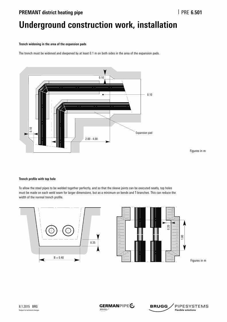
8.1.2015 BRG
PREMANT district heating pipe PRE
Subject to technical changes
0.20
1.80
6.501
0.10
0.10
2.00 - 4.00
0.10
0.35
B + 0.40
Underground construction work, installation
Trench widening in the area of the expansion pads
Thetrenchmustbewidenedanddeepenedbyatleast0.1monbothsidesintheareaoftheexpansionpads.
Figuresinm
Trench profile with top hole
Toallowthesteelpipestobeweldedtogetherperfectly,andsothatthesleevejointscanbeexecutedneatly,topholesmust be made on each weld seam for larger dimensions, but as a minimum on bends and T-branches. This can reduce the widthofthenormaltrenchprofile.
Figuresinm
Expansion pad

8.1.2015 BRG
PREMANT district heating pipe PRE
Subject to technical changes
Filling in the pipe trenches
6.502
Surrounding material (sand)
•Compactablewashedsand,max.particlesize8mm(0-8mm)•Finestparticlecomponent≤0.25mm,notmorethan8%ifpossible•Friableorsmallestpossibleloamcomponent
Asanalternative,so-calledcyclonesand/sludgesand,particlesize0-1mm,ispermitted(the'waste'fromwashedsand).CrushedglassisnotpermittedasasubstituteforsandwithPREMANTdistrictheatingpipe(itisallowedforFLEXWELL).
Embedding the pipe in sand (as per Trench Profile sheet)
• Coverage over crown of pipe - at least 10 cm.• Compaction–veryimportant!• Thesandmustbecompactlybeddedinorcompactedbyhand,withsuitableimplements(suchasaspadeor pick-axehandle)inlayersbetween,belowandnexttothepipes.Nocavitiesmustbecreated. Important:Donotdamagethesealingstripsandpipes!
Residual infill of the pipe trench
• Therestofthetrenchmustbefilledinwithlayersofcompactablematerial,suchasexcavatedmaterialand/orfine gravel which must be well compacted. Local regulations govern the use of excavated material and the minimum thicknessofthefinegravellayer.• To compact the material, use a vibrator providing max. 100 kPa pressure/unit of area. Earliest compaction: from 30 cm coverageofpipecrown.Remember:installpipewarningtapeandanyprotectivepipes(notoverthepipes) (approx.30cmabovepipecrown).• Toplayer:usehumusorHMTaccordingtoregulations.
Ifcoverageisinsufficient(<60cm)andinzoneswithheavytrafficloads,pressuredistributionplatesmustbeinstalledoverthesandlayertorelievepressureonthepipes.
Ingeneral,allconstructionandsafetyregulationsmustbefollowed.

8.1.2015 BRG
PREMANT district heating pipe PRE
Subject to technical changes
6.505
D
B
H
90
540
250
110
580
300
125
640
300
140
640
350
160
680
350
180
720
350
200
760
350
225
810
400
250
860
400
280
920
450
315
990
450
355
1070
500
400
1160
550
450
1260
600
500
1360
650
560
1480
750
630
1620
800
710
1780
900
800
1960
990
min. 1205060
PREMANT
B
90 D 200
H
House lead-inWall seal – neoprene rubber
Wall leadthrough
Wall opening
Basement/shaft
Monitoring box
Shrink closure
see sheet PRE 6.345
Wall sealing ring made of
profiledneoprenerubber;
see sheet PRE 6.355
Wall opening dimensions
Figuresinmm
Figuresinmm
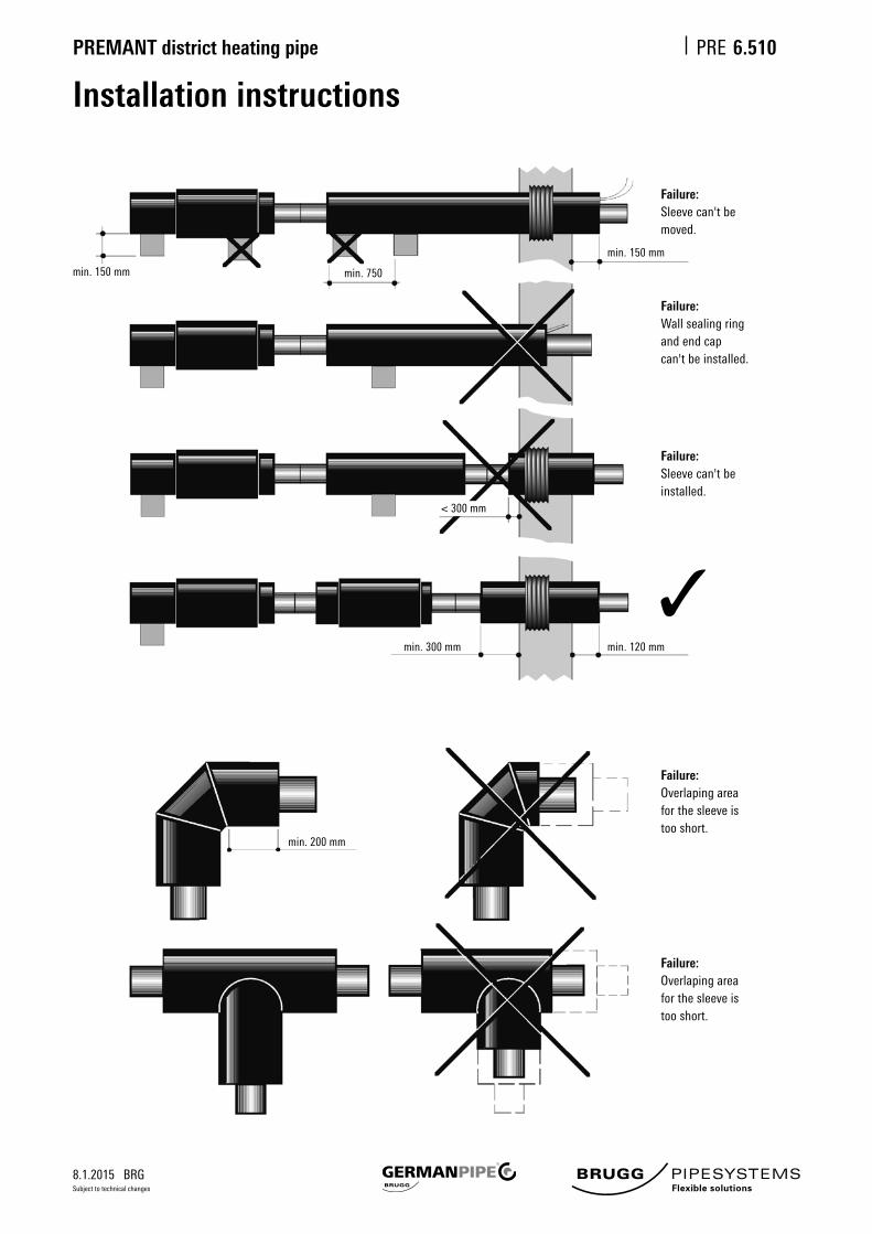
8.1.2015 BRG
PREMANT district heating pipe PRE
Subject to technical changes
6.510
Installation instructions
min. 150 mm
min. 150 mm
min. 750
< 300 mm
min. 300 mm min. 120 mm
min. 200 mm
Failure:Wall sealing ring and end cap can't be installed.
Failure:Sleeve can't be installed.
Failure:Overlaping area for the sleeve is too short.
Failure:Overlaping area for the sleeve is too short.
Failure:Sleeve can't be moved.

8.1.2015 BRG
PREMANT district heating pipe PRE
Subject to technical changes
6.515
a
B
A
A1
HL*
Steel pipe
DN
20
25
32
40
50
65
80
100
125
150
200
250
300
350
400
450
500
d
mm
26.9
33.7
42.4
48.3
60.3
76.1
88.9
114.3
139.7
168.3
219.1
273.0
323.9
355.6
406.4
457.2
508.0
Fixed point force
Fs max
kN
66.5
83.7
107.2
123.1
172.4
219.9
284.1
412.9
507.6
680.9
1000.6
1388.5
1847.0
2052.0
2592.0
2920.0
3240.0
Concrete block dimensions
B
m
0.8
0.8
1.0
1.0
1.2
1.4
1.6
2.0
2.2
2.5
3.0
3.5
4.2
4.5
5.2
5.6
5.6
A1
m
0.40
0.40
0.40
0.45
0.55
0.65
0.80
0.95
1.15
1.40
1.70
2.10
2.25
2.40
2.40
2.60
2.60
A
m
0.8
0.8
0.8
0.9
1.1
1.2
1.3
1.6
1.7
2.0
2.4
2.9
3.2
3.3
3.5
3.6
3.8
L*
m
0.8
0.8
0.8
0.8
1.0
1.0
1.0
1.0
1.0
1.3
1.3
1.3
1.5
1.5
1.8
2.0
2.0
Pipe distance
a
mm
270
270
280
280
295
320
340
390
415
450
550
680
745
810
890
890
980
Concrete block for fixed pointFormaximumfixedpointforces
Fordivergentfixedpointforcesandsoilconditions,thefoundationdimensionsmustbecalculated.
Calculation basis for the size of the concrete block• Max.thrustfor2pipes:Fsmax=2·As·dT,[dT=165N/mm²,∆T=70°K]• Coverage height H = 0.8 m• Foundationdimensionsarebasedonafrictionalangleof=32.5°forfriablesoils(coefficientoffriction=0.40)• Apparentdensity=18kN/m³•Groundspecificationacc.DVGWGW310
Concrete quality• P 350 to DIN 1045, impermeable to water with armouring
L* max. width

8.1.2015 BRG
PREMANT district heating pipe PRE
Subject to technical changes
6.520
150 4
3 21
6
min.
120 150
5
500
1
23
min. 100
1000
4
5
Sectional drainage, sectional venting
1Valve,suppliedbycustomerorothers2 Shrink-on closure, delivered loose3 Expansion pad4 Sand5 Lean concrete6Soakawaygravel
L as
sta
ted
Figuresinmm
L as statedSpecial version

8.1.2015 BRG
PREMANT district heating pipe PRE
Subject to technical changes
6.525
DN
20
25
32
40
50
65
80
100
125
150
200
250
D1
mm
125
125
140
140
160
180
200
250
280
315
355
450
H
mm
470
470
470
490
500
510
520
560
570
590
630
670
D2
mm
250
250
250
300
300
D2 D2
200 D1 200 D1 200
1
2
3
4
5
6
H
>D2
Underground construction for ball valveShafts with drive-over cast cover
1Castcover,drive-over(e.g.VonRoll)2 Cement pipe3 Ball valve 4 Expansion pad5 Support plate6Sandfilling(particlesize0-8mm)
Figuresinmm

8.1.2015 BRG
PREMANT district heating pipe PRE
Subject to technical changes
6.530
40 c
m
Tappingsystemsaredesignedtoproducepipebranchesunderpressure.Today'sequipmentandcomponentsaretheresultsofaproductdevelopmentprocesswhichhascombinedprovensolutionswithnewfindings.Thistappingmethodachievesmajorcostsavingsthankstosimpleandcost-effectiveworkingprocedures,andfittingworkwhichcanbecar-riedoutquicklyandreliablywithoutinterruptionstooperation.
The tapping device for weldable joints on steel pipes and containers can be used for branch dimensions of DN 25 to DN100,upto25barand140°C.Onbranches,thetappingblockisweldedtotheparttobetapped,eitherdirectlyorwithaweldringifnecessary.
Thetappingblocksaredesignedwithareducedopening.Theycanbeusedindistrictheatingpipesandvariousprocesspipes.
Tappingpipebranchesunderpressurehastheadvantagethattheycanalwaysbeproducedinthedesiredlocationatalater stage.
Largerdimensionscanbeexecutedwithanothersystemonrequest.
Tapping technologySystemdescription
Important:Tappingtechnologymustonlybeprocessedbyspecialiststaff.

8.1.2015 BRG
PREMANT district heating pipe PRE
Subject to technical changes
6.531
Dimension DN 25* DN 32 DN 40* DN 50 DN 65 DN 80 DN 100
Ball opening 25 25 40 40 50 65 80
Bore diameter 24 24 40 40 48 65 79
Flowvalue(KVS)[m³/h] 26 41 68 112 200 380 620
A1(houseconnectionbranch) 33.7x2.9 42.4x2.9 48.3x2.9 60.3x3.1 76.1x3.1 88.9x3.2 114.3x3.6
A2(connectingbranchtomainpipe) 37.0x5.8 37.0x5.8 54.0x6.7 54.0x6.7 63.0x7.0 82.0x8.0 100.0x9.0
B 60.3 60.3 88.9 88.9 114.3 133.0 159.0
H 46.0 46.0 57.0 57.0 70.0 80.0 92.0
L 145.0 145.0 200.0 200.0 260.0 265.0 275.0
Sealing screw, hexagon socket 10 10 10 10 14 14 14
Weight[kg] 1.3 1.2 3.5 3.4 5.1 6.7 11.3
Min.mainpipeØ DN32 DN40 DN50 DN65 DN80 DN100 DN125
Min.casingpipeØ(branch) 110 125 125 140 160 180 225
Figuresinmm
L
A1H
A2 B
Tapping technologyDimensions and measurements
Fittings with reduced through passage
Tapping ball valve with fully welded housing in St 37Ball in nickel chromium steel with PTFE seals
* Dimensions with full through passageLargerdimensionswithdifferenttappingsystemsonrequest
Hexagon screw

8.1.2015 BRG
PREMANT district heating pipe PRE
Subject to technical changes
6.532
Tapping technologyPreparation of weld seam and seam structure
Weld-on end with seam preparation
Thread for tapping tool
Imbus screw
Tightenaftertheconnectingpipeiscommissioned(blocktheball)and
weldtothehousingallthewayround.
Placethetappingfittingdirectlyon
the base pipe, without a gap.
Weld seam structure:E-weld(2-3layers)withKbelectrodes,basic(alkaline)TypeE5155B10DIN1913Ø2.5mm
Important during welding!• Ballmustbeexactlyintheopenposition.• AvoidexcessivetemperaturestressontheTeflonsealsbycoolingthefittingbetweentheindividual weldseamlayers(coolthefittingwithawetcloth/waitingtimebetweenindividualweldseamlayers)
Make sure that no welding deposit penetrates the inside of the tapping fitting.Bevellingofweld-onendasperDIN2559,jointtype22
1
60°
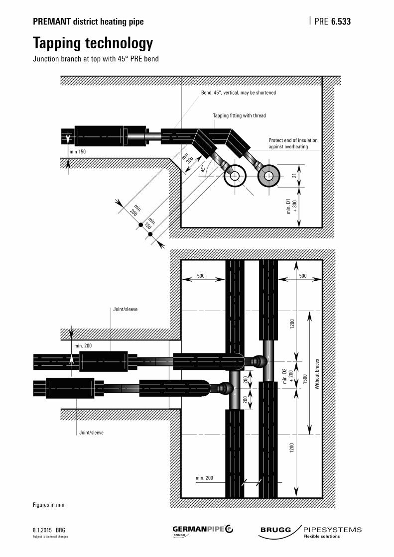
8.1.2015 BRG
PREMANT district heating pipe PRE
Subject to technical changes
6.533
Tapping technologyJunction branch at top with 45° PRE bend
Bend,45°,vertical,maybeshortened
Tappingfittingwiththread
min. 200
500500m
in. D
2 +
200
D1
45°
1200
1500
1200
200
200
Protect end of insulationagainst overheating
min. 200
Joint/sleeve
Joint/sleeve
min
. D1
+ 3
00
With
out b
race
s
min 150
min.200min.150
min.
300
Figuresinmm

8.1.2015 BRG
PREMANT district heating pipe PRE
Subject to technical changes
6.534
Tapping technologyJunction branch at top with 45° welded bend
Welded bend
Tappingfittingwiththread
Adapter
min. 150
min. 200
min. 200
500 500
D2
min
. D1
+ 3
00m
in. 6
0D1
46°
1200
1500
1200
500
200
200
Figuresinmm

8.1.2015 BRG
PREMANT district heating pipe PRE
Subject to technical changes
6.535
Tapping technologyJunction branch at bottom with 45° PRE bend
min. 150
min. 200
min. 200
500 500
D2
46°
1200
1500
1200
200
200
1200
1500
Bend,45°,vertical,maybeshortened
TappingfittingwiththreadProtect end of insulationagainst overheating
200
150
L
With
out b
race
sJoint/sleeve
Joint/sleeve
min
. D2
+ 2
00
Figuresinmm

8.1.2015 BRG
PREMANT district heating pipe PRE
Subject to technical changes
6.536
Tapping technologyJunction branch at bottom with 45° welded bend
min. 200
min. 200
500 700
D2
1200
1500
1200
200
200
With
out b
race
s
min
. D2
+ 2
00
Welded bend, 5d
Tappingfittingwiththread
Adapter
min. 150 min
60
1200
45°
1500
Figuresinmm

8.1.2015 BRG
PREMANT district heating pipe PRE
Subject to technical changes
6.537
Tapping technologyJunction branch at top with 90° PRE bend
Parallel branch: limb length: max. 2.5 m
min. 150
min. 200
min. 200
500 500
D2
1200
1500
1200
200
200
D1
Bend,90°,vertical,maybeshortened
Tappingfittingwiththread
Same side as branch
Protect end of insulationagainst overheating
With
out b
race
s
Joint/sleeve
Joint/sleeve
min
. D2
+ 2
00m
in. D
1 +
300
min. 150
min. 150
Figuresinmm