Embed Size (px)
Citation preview
ANS MC2015 - Joint International Conference on Mathematics and Computation (M&C), Supercomputing in Nuclear Applications (SNA) and the Monte
Carlo (MC) Method • Nashville, TN • April 19-23, 2015, on CD-ROM, American Nuclear Society, LaGrange Park, IL (2015)
PRELIMINARY INVESTIGATION OF MCNP6 UNSTRUCTURED MESH
GEOMETRY FOR RADIATION FLUX CALCULATIONS INVOLVING
SPACE ENVIRONMENT
Kristofer Zieb, Hui Lin, Wei Ji, Peter F. Caracappa, X. George Xu
Nuclear Engineering Program, Rensselaer Polytechnic Institute
Troy, NY 12180, USA
[email protected]; [email protected]; [email protected]; [email protected]; [email protected]
ABSTRACT
The latest release of MCNP6 contains the capability to represent geometry in unstructured
meshes. The unstructured mesh features, however, have been tested with only limited examples to
date. The aim of this paper is to examine the use of the new unstructured mesh features for space
radiation flux calculations involving a space habitat during a solar particle event. High energy
proton transport, alongside its secondary particles, a modeling capability integrated from MCNPX,
was tested with MCNP6’s unstructured mesh feature to gain insight into the potential uses and
limitations of MCNP6’s development. Abaqus was used to generate an unstructured tetrahedral
mesh of a space habitat structure, which was then used with MCNP6.1.1 Beta to simulate a Solar
Particle Event (SPE) consisting of a high flux of protons of energies up to 500 MeV. Trial
simulations were performed using 1st and 2
nd order tetrahedral meshes, however it is concluded
that high energy proton transport still requires further development.
Key Words: Space, Unstructured Mesh, MCNP6, Solar Particle Event
1 INTRODUCTION
MCNP6’s recent release combines MCNP5 and MCNPX into a single software package, and
introduces several new features [1], amongst them the support for unstructured 3D mesh
geometries. The inclusion of unstructured mesh geometry representations allows for models
created using a CAD program to be imported through Abaqus or Exodus-II into MCNP [2,3].
For modeling complex geometry types, the use of a CAD program is superior to the traditional
constructive solid geometry (CSG) of MCNP with regards to both ease of use, and the ability to
accurately represent complex, non-parametric surfaces that could only be approximated by CSG
previously [4].
This work aims to extend previous space radiation research performed by the Rensselaer
Radiation Measurement and Dosimetry Group (RRMDG) in collaboration with NASA’s Space
Radiation Analysis Group (SRAG) [5]. Previous work involved the use of MCNPX and FLUKA
to simulate radiation transport in a realistic space habitat originating from CAD geometry. A
workflow was established for both radiation transport codes and the use of CSG geometry was
compared to the geometry generated from a CAD model through FLUDAG, a combination of
FLUKA and a modified geometry module capable of processing CAD geometry for the FLUKA
environment, developed through the Direct Accelerated Geometry for Radiation Analysis and
Design (DAGRAD) element of the RadWorks Project of NASA.

Zieb, Lin, Ji, Caracappa and Xu
Page 2 of 10
1.1 Previous Limitations
The space radiation simulations by the RRMDG were performed before the opportunity to
use the MCNP6.1.1 Beta release, including the addition of proton transport through the
unstructured mesh geometry [6]. The heavy ion transport capability of MCNPX was relied on
heavily for accurate simulation of Solar Particle Events (SPE), but geometry was limited to
representations in CSG. The DAGRAD module used for FLUKA has an analogous module for
allowing CAD geometry to be used in MCNP, with the most recent iteration capable of
integrating with MCNP5, which is unable to simulate the physics of SPEs. This limited the
RRMDG to a CSG representation of a habitat with a voxelized computational phantom, the VIP-
Man phantom in MCNPX to achieve the desired simulation.
Work performed using the FLUDAG workflow required lengthy pre-processing of the CAD
geometry being used alongside an extensive building procedure of the DAGRAD toolkit. The
simulation was also limited by not allowing hybrid geometries to be constructed, that is
combining CSG with the pre-processed CAD geometries.
1.2 Radiation Transport Geometry Models
The inclusion of the support for unstructured mesh capabilities in MCNP6 allows state-of-
the-art CAD/CAE tools, like Abaqus/CAE, to generate unstructured mesh representations of
solid models for the radiation transport code [2]. Previous methods of implementing detailed
structures or human phantoms relied on CSG approximations to true form, through the use of
voxel representations, with some work having been done on the use of boundary representation
[7,8]. With unstructured meshes, a greater degree of approximation to real world geometries can
be achieved than that provided by CSG previously [9]; as the voxelization process tends to limit
the ability to accurately represent thin structures, meaning that proper energy deposition and dose
data are also limited.[7]
With boundary representation, specifically non-uniform rational B-spline (NURBS) or
polygonal mesh surfaces, reductions in geometric accuracy from voxelization can be avoided.
However for full implementation of NURBS surfaces, direct Monte Carlo simulation is not
currently available, requiring either voxelization of the geometry, which causes aforementioned
problems, or a conversion to polygonal mesh surfaces.
Growing evidence has shown that polygonal surfaces, although geometrically more precise,
tend to be computationally slower than equivalent voxelized geometries.[8] The gap between
performance and accuracy is bridged with the option to use unstructured meshing.
1.3 Radiation Types in MCNP6.1.1 Beta with Unstructured Mesh
Deciding on which radiation transport suite to use is dependent on the characteristics of the
radiation source and geometry to be modeled. The previous work performed by RRMDG
involved protons of energies up to 500MeV incident upon aluminum shielding, meaning a host
of secondary particles will be generated. This was a primary motivator in selecting MCNPX as
well as FLUDAG for previous simulations.
The current release of MCNP6.1.1 Beta does not track several high-energy particle types
through unstructured mesh, meaning several particles tracked in previous simulations are
unavailable currently [6]. Table I provides a listing of the particles that are not tracked.

MCNP6 Unstructured Mesh Geometry in a Space Radiation Environment
Page 3 of 10
Table I. Heavy neutral particles not available in MCNP6 with unstructured mesh geometry [10]
Name Name (Longform) Symbol Mass(MeV)
lambda0 (Λ
0) Lambda Baryon l 1.116 10
3
cascade0 (Ξ0) Xi Baryon X 1.315 103
cascadec0 (Ξc
0) Charmed Xi Baryon ? 2.470 10
3
D0 D Meson (neutral) D 1.864 10
3
B0 B Meson (neutral) B 5.279 10
3
Bs0 Strange B Meson Q 5.375 10
3
These particles are produced in a high energy physics environment and, given their large
masses, are a matter of interest for the RRMDG’s simulations of the space environment.
Currently no checking has been reported on the interactions of unstructured mesh with light ions
and other charged particles other than electrons and protons. This leaves a substantial quantity of
particles previously simulated using MCNPX to be explored in MCNP6 with the unstructured
mesh geometry. Previously, the simulation had tracked a total of 23 particles, including the
neutron, proton, and electron, with a majority of these particles consisting of light ions, however
the transport model has been further reduced to include just protons, electrons and photons.
The aim of this paper is to examine the use of the new unstructured mesh features in
MCNP6.1.1 Beta for space radiation transport calculations involving a space habitat during a
solar particle event. The study of the advantages and limitations of the current version are hoped
to be helpful to the ongoing development and testing of MCNP6 at Los Alamos National Lab
(LANL).
2 MATERIALS AND METHODS
The project consisted primarily of establishing a full workflow through MCNP6.1.1 Beta
with the unstructured mesh function from a previously used CAD model of a space habitat.
2.1 Meshing Space Habitat
The CAD model used during previous collaborative work with NASA is that of a realistic
space habitat pictured in Fig. 1. The model is a mock-up of a potential space habitat that may be
used outside of low earth orbit, or on the surface of another planet.

Zieb, Lin, Ji, Caracappa and Xu
Page 4 of 10
Figure 1. Section views of halves of the NASA habitat
As can be seen above the initial habitat is highly detailed with many support baffles, as well
as shelving units and various tanks. Each of the landing support structures at the base of the
habitat has multiple pins and screws modeled as discrete parts as well. It was desired to keep
element count relatively small when meshing for initial trials, as well as to increase performance
for the radiation transport involving tracking many secondary particles. To this aim a reduced
model of the habitat structure was used, with many of the finer details removed from the
structure. Fig. 2 depicts this modified model.
Figure 2. Section views of halves of the simplified NASA habitat
The simplified habitat model was then the starting point for developing the workflow of the
simulation. Meshing was performed in Abaqus, making use of documentation from LANL [11].
Initial steps required import of the multiple parts comprising the habitat into the Abaqus
environment so that they could be merged and meshed. Upon import into Abaqus, several
geometric features of the original habitat were unable to merge to a final part. This is primarily
due to “zero-volume” geometry issues at doorways which prevent a full merging of the model
into a single part. To quickly resolve this issue, the habitat was partitioned into sections and the
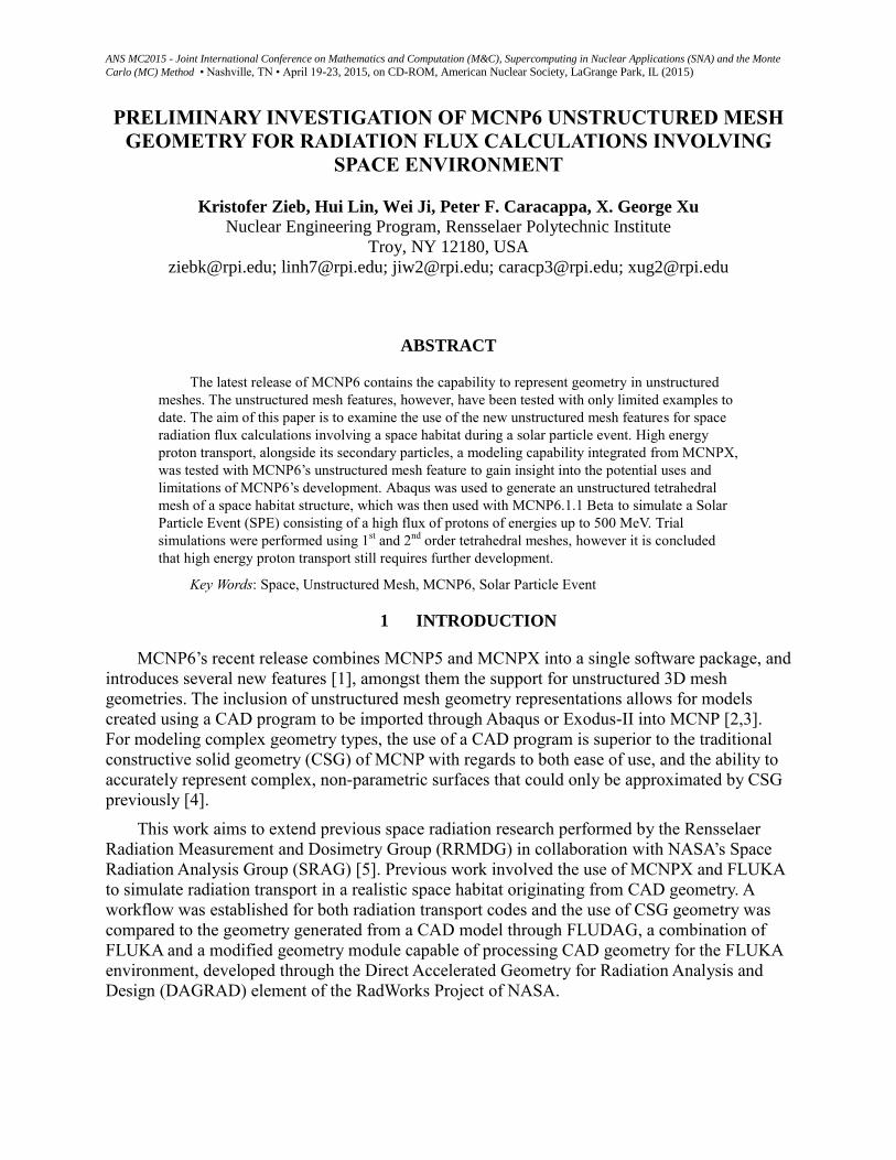
most complete “water-tight” portion of the habitat was meshed. Fig. 3 depicts this small section
of the habitat in Abaqus.
MCNP6 Unstructured Mesh Geometry in a Space Radiation Environment
Page 5 of 10
Figure 3. Tetrahedral mesh of small habitat chamber in Abaqus
It can be seen from Fig.3 that the chamber has been fully meshed, and both 1st and 2
nd
order tetrahedral elements were examined, using the free tetrahedral mesh algorithm of Abaqus.
The .inp files are then generated, containing all of the node and element information.
2.2 Preprocessing for MCNP6
The .inp file generated from Abaqus contains part designations as well as the coordinates of
every node and element contained within the meshed chamber. The .inp file requires manual
editing to designate statistical and material sets of elements and nodes, per the current
MCNP6.1.1 Beta unstructured mesh workflow. The preprocessing utility packaged with MCNP6
is um_pre_op611, and amongst its other capabilities is the possibility to convert an Abaqus .inp
file into an MCNP input deck [3].
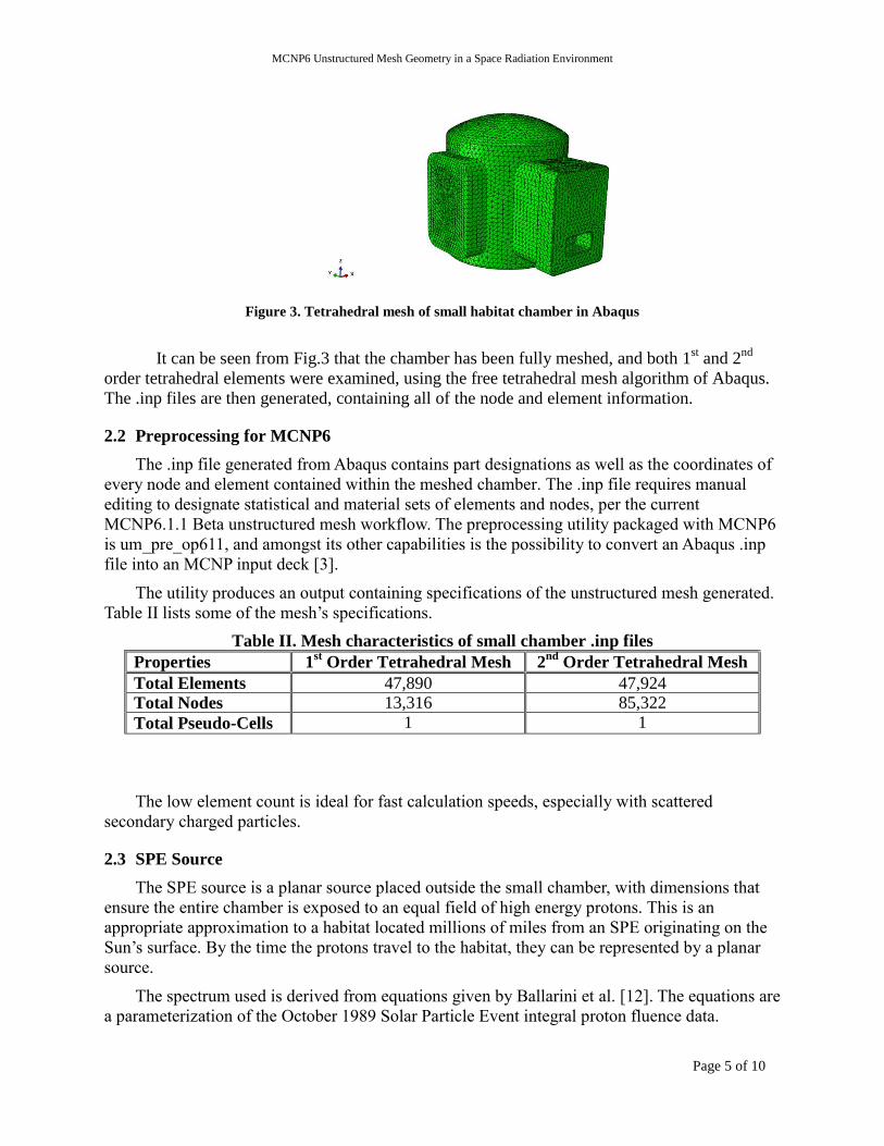
The utility produces an output containing specifications of the unstructured mesh generated.
Table II lists some of the mesh’s specifications.
Table II. Mesh characteristics of small chamber .inp files
Properties 1st Order Tetrahedral Mesh 2
nd Order Tetrahedral Mesh
Total Elements 47,890 47,924 Total Nodes 13,316 85,322
Total Pseudo-Cells 1 1
The low element count is ideal for fast calculation speeds, especially with scattered
secondary charged particles.
2.3 SPE Source
The SPE source is a planar source placed outside the small chamber, with dimensions that
ensure the entire chamber is exposed to an equal field of high energy protons. This is an
appropriate approximation to a habitat located millions of miles from an SPE originating on the
Sun’s surface. By the time the protons travel to the habitat, they can be represented by a planar
source.
The spectrum used is derived from equations given by Ballarini et al. [12]. The equations are
a parameterization of the October 1989 Solar Particle Event integral proton fluence data.

Zieb, Lin, Ji, Caracappa and Xu
Page 6 of 10
𝐽 = 𝐽0𝑒
(−𝑅 𝑅0⁄ )
(1)
In Eq. 1 J is the integral fluence (protons/cm2) and R is the proton rigidity (momentum per unit
charge. R is expressed in the following manner:
𝑅 = √𝐸2 + 2 × 938.26𝐸 (1)
Ballerini provides suggested values for J0 and R0, with J0=5.11 1010
protons/cm2 and R0=93.28
MV. These provide a spectrum that is more accurate for higher energies (E > 100 MeV), which is
ideal as the lower energies of protons have a range that does not exceed the 2 g/cm2 density
thickness of the aluminum chamber. The generated spectrum extends to 500 MeV.
3 RESULTS
The 1st order tetrahedral mesh simulation with protons was able to run to completion, with
none of the lost particle messages of the 2nd
order tetrahedral mesh simulation, however the
resultant proton energy deposition data section of the .eeout file contained all zeroes as well. The
proton flux, as with the second order mesh, was successfully recorded however. Fig. 4 shows the
proton flux through the 1st order tetrahedral mesh of the model.
Figure 4: Proton flux recorded for 1st order tetrahedral mesh from the front (left) and rear (right) views
The figure on the left in Fig. 4 sharply illustrates the use of the planar source, as the surfaces
parallel to the source show high fluxes, i.e. the door and the wall of the habitat, while surfaces
perpendicular to the planar source, the farther door, are relatively untouched by the protons. In
the right image of Fig. 4, the profile of the door can be clearly distinguished, due to the
additional thickness of material allowing more interactions of incident protons to occur.
The prepared 2nd
order tetrahedral mesh simulation with protons suffered repeated failed
runs due to a particle tracking error. The .eeout file generated from the simulation contained all
zeroes for deposited energy in the data set results section of the file for protons. Conversion of
the .eeout file to a .obj file for visualization yielded the original small habitat chamber model
mesh with no data ascribed to any individual elements. However, the proton flux was
MCNP6 Unstructured Mesh Geometry in a Space Radiation Environment
Page 7 of 10
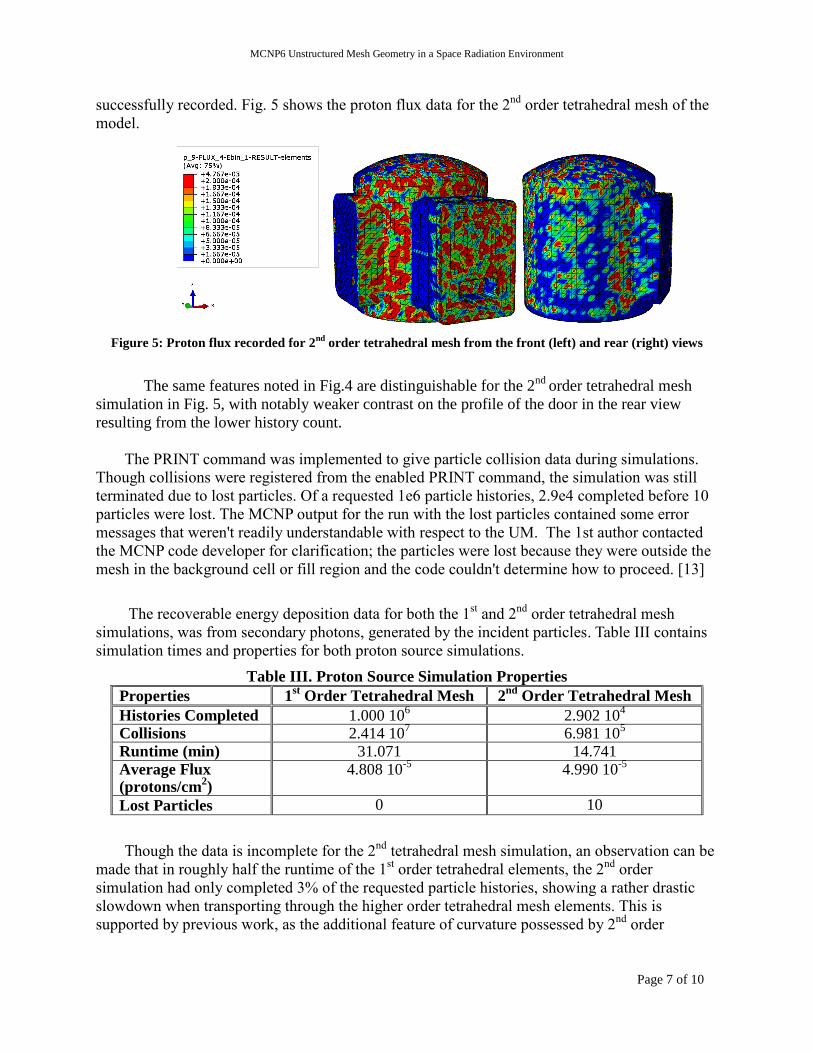
successfully recorded. Fig. 5 shows the proton flux data for the 2nd
order tetrahedral mesh of the
model.
Figure 5: Proton flux recorded for 2nd
order tetrahedral mesh from the front (left) and rear (right) views
The same features noted in Fig.4 are distinguishable for the 2nd
order tetrahedral mesh
simulation in Fig. 5, with notably weaker contrast on the profile of the door in the rear view
resulting from the lower history count.
The PRINT command was implemented to give particle collision data during simulations.
Though collisions were registered from the enabled PRINT command, the simulation was still
terminated due to lost particles. Of a requested 1e6 particle histories, 2.9e4 completed before 10
particles were lost. The MCNP output for the run with the lost particles contained some error
messages that weren't readily understandable with respect to the UM. The 1st author contacted
the MCNP code developer for clarification; the particles were lost because they were outside the
mesh in the background cell or fill region and the code couldn't determine how to proceed. [13]
The recoverable energy deposition data for both the 1st and 2
nd order tetrahedral mesh
simulations, was from secondary photons, generated by the incident particles. Table III contains
simulation times and properties for both proton source simulations.
Table III. Proton Source Simulation Properties
Properties 1st Order Tetrahedral Mesh 2
nd Order Tetrahedral Mesh
Histories Completed 1.000 106 2.902 10
4
Collisions 2.414 107 6.981 10
5
Runtime (min) 31.071 14.741 Average Flux (protons/cm
2)
4.808 10-5
4.990 10-5
Lost Particles 0 10
Though the data is incomplete for the 2nd
tetrahedral mesh simulation, an observation can be
made that in roughly half the runtime of the 1st order tetrahedral elements, the 2
nd order
simulation had only completed 3% of the requested particle histories, showing a rather drastic
slowdown when transporting through the higher order tetrahedral mesh elements. This is
supported by previous work, as the additional feature of curvature possessed by 2nd
order
Zieb, Lin, Ji, Caracappa and Xu
Page 8 of 10
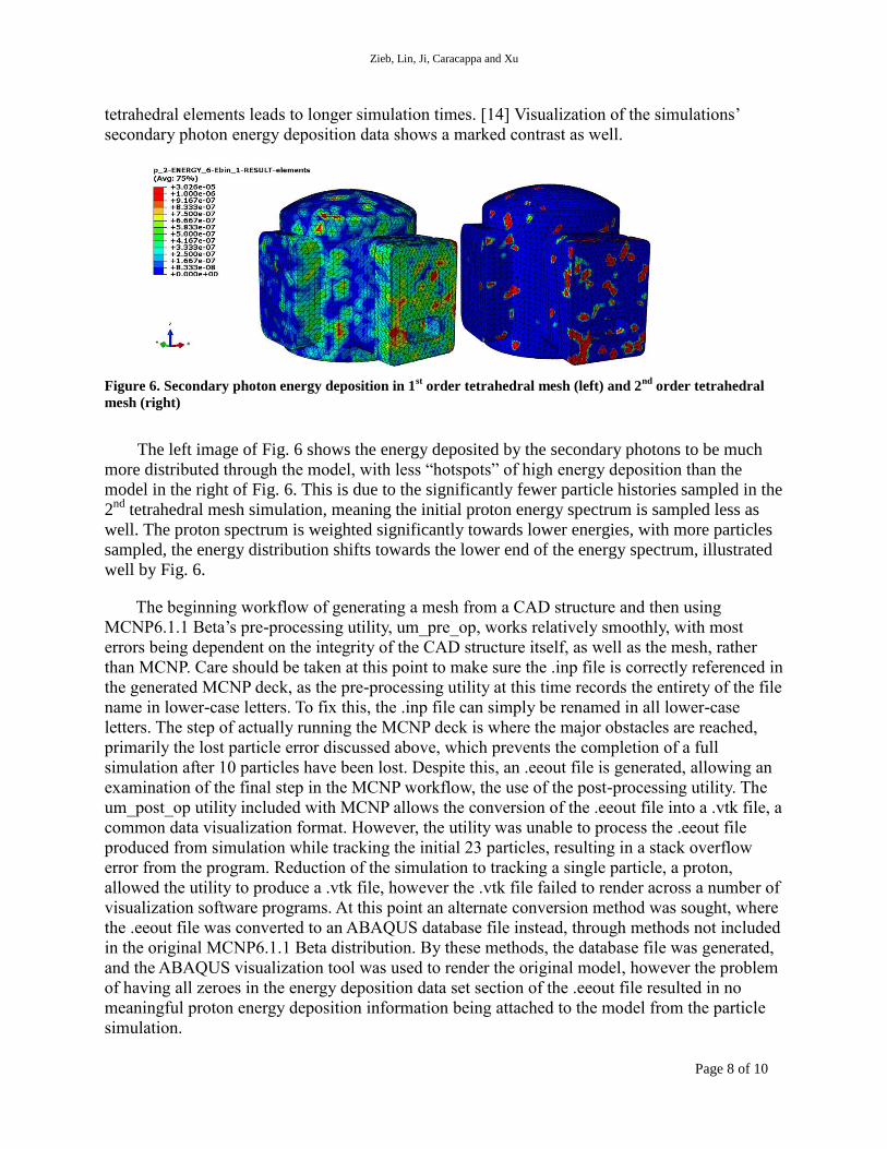
tetrahedral elements leads to longer simulation times. [14] Visualization of the simulations’
secondary photon energy deposition data shows a marked contrast as well.
Figure 6. Secondary photon energy deposition in 1st order tetrahedral mesh (left) and 2
nd order tetrahedral
mesh (right)
The left image of Fig. 6 shows the energy deposited by the secondary photons to be much
more distributed through the model, with less “hotspots” of high energy deposition than the
model in the right of Fig. 6. This is due to the significantly fewer particle histories sampled in the
2nd
tetrahedral mesh simulation, meaning the initial proton energy spectrum is sampled less as
well. The proton spectrum is weighted significantly towards lower energies, with more particles
sampled, the energy distribution shifts towards the lower end of the energy spectrum, illustrated
well by Fig. 6.
The beginning workflow of generating a mesh from a CAD structure and then using
MCNP6.1.1 Beta’s pre-processing utility, um_pre_op, works relatively smoothly, with most
errors being dependent on the integrity of the CAD structure itself, as well as the mesh, rather
than MCNP. Care should be taken at this point to make sure the .inp file is correctly referenced in
the generated MCNP deck, as the pre-processing utility at this time records the entirety of the file
name in lower-case letters. To fix this, the .inp file can simply be renamed in all lower-case
letters. The step of actually running the MCNP deck is where the major obstacles are reached,
primarily the lost particle error discussed above, which prevents the completion of a full
simulation after 10 particles have been lost. Despite this, an .eeout file is generated, allowing an
examination of the final step in the MCNP workflow, the use of the post-processing utility. The
um_post_op utility included with MCNP allows the conversion of the .eeout file into a .vtk file, a
common data visualization format. However, the utility was unable to process the .eeout file
produced from simulation while tracking the initial 23 particles, resulting in a stack overflow
error from the program. Reduction of the simulation to tracking a single particle, a proton,
allowed the utility to produce a .vtk file, however the .vtk file failed to render across a number of
visualization software programs. At this point an alternate conversion method was sought, where
the .eeout file was converted to an ABAQUS database file instead, through methods not included
in the original MCNP6.1.1 Beta distribution. By these methods, the database file was generated,
and the ABAQUS visualization tool was used to render the original model, however the problem
of having all zeroes in the energy deposition data set section of the .eeout file resulted in no
meaningful proton energy deposition information being attached to the model from the particle
simulation.
MCNP6 Unstructured Mesh Geometry in a Space Radiation Environment
Page 9 of 10
4 CONCLUSIONS
The 1st order tetrahedral simulation ran to completion, however no energy deposition proton
data was recorded to the .eeout file, only fluxes, while substantial secondary photon data was
recorded, and some sense of particle interaction could be gained from the visualization.
Lost particles were the most frequent cause of an early termination of a simulation. The
source configuration is such that all particles are directed towards the small habitat chamber
model within the MCNP simulation. Despite this, lost particles were still recorded.
The lost particles are believed to be an issue with the tracking of charged particles by
MCNP6.1.1 Beta in unstructured mesh geometry. The elements used in the simulation that
terminated early are also 2nd
order tetrahedrals, and given that proton transport was just
introduced in the MCNP6.1.1 release, not all the mesh element types available have been fully
tested with this particle type. Correspondence with the lead developer of MCNP6’s unstructured
mesh feature supports the fact that there are still design features to be implemented with regards
to particle tracking.
MCNP6.1.1 Beta is highly robust radiation transport software, and the inclusion of
unstructured mesh geometries is an exciting development. While the true reason for repeatedly
terminated runs of the 2nd
order tetrahedral mesh simulation is still being investigated, it is clear
that the MCNP6 developers at LANL have been working to refine features related to the
tetrahedral meshing in MCNP6.
5 ACKNOWLEDGMENTS
Dr. Tim Goorley and Dr. Roger Martz from Los Alamos National Lab provided very helpful
assistance on MCNP6 tetrahedral mesh features during this project. Dr. Kerry Lee from Nasa
provided guidance in a previous project that inspired this work. The first author would also like
to acknowledge the support by the RPI-NRC Nuclear Fellowship Program under the grant
NRCHQ-13-G-38-0035.
6 REFERENCES
1. T. Goorley, M. James, T. Booth, F. Brown, J. Bull, L. J. Cox, J. Durkee, J. Elson, M. Fensin,
R. A. Forster, J. Hendricks, H.G. Hughes, R. Johns, B. Kiedrowski, R. Martz, S. Mashnik, G.
Mckinney, D. Pelowitz, R. Prael, J. Sweezy, L. Waters, T. Wilcox, T. Zukaitis, “Initial
MCNP6 Release Overview - MCNP6 version 1.0”, LA-UR-13-22934 (2013)
2. C. A. Angelo, S. S. McCready, K. C. Kelley, “Modeling Radiation Transport Using MCNP6
and Abaqus/CAE,” 2012 Simulia Community Conference, Providence RI, May 15-17 2012,
pp.332-345
3. R.L. Martz, “The MCNP6 Book on Unstructured Mesh Geometry: User's Guide”, LA-UR-
11-05668-rev8 (2014)
4. C. A. Anderson, K. C. Kelley, J. T. Goorley, “Mesh Human Phantoms with MCNP,” 2012
Simulia Community Conference, Providence RI, May 15-17 2012, pp.556-568
5. K. Lee, “Path Toward a Unified Geometry for Radiation Transport,” 40th COSPAR Scientific
Assembly, Moscow Russia, August 2-10 2014
Zieb, Lin, Ji, Caracappa and Xu
Page 10 of 10
6. T. Goorley, “MCNP6.1.1-Beta Release Notes”, LA-UR-14-24680 (2014)
7. C. H. Kim, J. H. Jeong, Y. S. Yeom, “Recent Advances in Computational Human Phantom
for Monte Carlo Dose Calculation,” Progress in Nuclear Science and Technology, 3, pp.7-10
(2012)
8. Y. S. Teom, J. H. Jeong, M. C. Han, C. H. Kim, “Tetrahedral-mesh-based Computational
Human Phantoms for Fast Monte Carlo Dose Calculations,” Physics in Medicine and
Biology, 59, pp.3173-3185 (2014)
9. T. P. Burke, B. C. Kiedrowski, R. L. Martz, W. R. Martin, “Reactor Physics Verification of
the MCNP6 Unstructured Mesh Capability,” International Conference on Mathematics and
Computational Methods Applied to Nuclear Science and Engineering, Sun Valley ID, May 5-
9 2013, pp. 1064-1072
10. L.S. Waters, Ed., “MCNPX User's Manual, Version 2.3.0”, LA-UR-02-2607 (2002)
11. K. Marshall, “Creating A Merged Single-Part Abaqus Model For Use In MCNP6”, LA-UR-
11-04369 (2011)
12. F. Ballarini., et al. "Role of Shielding in Modulating the Effects of Solar Particle Events:
Monte Carlo Calculation of Absorbed Dose and DNA Complex Lesions in Different
Organs." Advances in Space Research, 34.6, pp. 1338-1346 (2004)
13. R.L.Martz, LANL, private communication, 2014.
14. Karen C. Kelley, Roger L. Martz, and David L. Crane, "Riding Bare-back on Unstructured
Meshes for 21st Century Criticality Calculations", PHYSOR 2010 - Advances in Reactor
Physics, Pittsburgh, Pennsylvania, USA, May 9-14, LA-UR-09-7320 (2010).