Embed Size (px)
Citation preview

1 J
NACA
RESEARCH MEMORANDUM
PRELIMINARY INVESTIGATION IN J33 TURBOJET ENGINE OF SEVERAL
ROOT DESIGNS FOR CERAMAL TURBINE BLADES
By George C. Deutsch, Andre J. Meyer, Jr. and William C. Morgan
Lewis Flight Propulsion Laboratory Cleve land, Ohio
NATIONAL ADVISORY COMMITTEE FOR AERONAUTICS
WASHINGTON January 26 , 1953
https://ntrs.nasa.gov/search.jsp?R=19930087393 2018-02-01T01:16:38+00:00Z


1 S NACA RM E52Kl3
NATIONAL ADVISORY COMMITTEE FOR AERONAUTICS
RESEARCH MEMORANDUM
PRELIMINARY INVESTIGATION IN J33 TURBOJET ENGINE OF SEVERAL
ROOT DESIGNS FOR CERAMAL TURBINE BLADES
By George C. Deutsch, Andre J. Meyer, Jr., and William C. Morgan
SUMMARY
The practicability of using ceramals with comparatively low strategic material content for the blades of aircraft turbines was determined in an experimental investigation. Four blade root configurations were examined.
The most favorable results were obtained for ceramal turbine blades with single serration interlock and dovetail root configurations. Six of the interlock type were operated in a J33-A-33 engine for 68 hours, 23 minutes at rated service speed and six of the dovetail type were operated for 58 hours, 28 minutes at rated speed. This result confirms the conclusions of previous static design studies.
INTRODUCTION
Among the more important problems confronting the designers of aircraft-engine turbine blades is the requirement that alloying elements which are not domestically available be held to a minimum. This restriction imposes serious limitations on thrust and operating temperature of engines, particularly on the expendable types intended for use in guided missiles. Mixtures of metals and ceramics (ceramals) have therefore been proposed for use in the blades of aircraft turbines to conserve strategic alloying elements and to permit the use of higher operating temperatures. It has been shown (references 1, 2, and 3) that titanium carbide base ceramals possess long and short time elevated temperature tensile strength properties which are adequate for most turbine blades and possess also good thermal shock resistance.
References 3 and 4 indicate that the first, and perhaps greatest, problem to be solved in the utilization of these materials is to devise ways of retaining them in the t~rbine wheel. This problem is present because these materials have very little or no ability to deform in short

2 NACA RM E52Kl3
times at the use temperature. In general) fastening devices suitable for use with these materials must first have a geometry compatible with a material which appears sensitive to stress concentrations) and second) their design must be such as to minimize the effects of mismating between the ceramal blade and the alloy wheel.
The experimental investigation described herein is preliminary and consisted of evaluating the service life of each of four ceramal blade root designs. One of these designs was the conventional fir-tree configuration in general use for alloy blades; the others were special designs based on analys is of the properties of the ceramal-blade material and on data obtained at the NACA Lewis laboratory during a previous investigation.
The engine chosen for this program is the J33. The reasons for this choice were that the engine is one in which the centrifugal stress imposed on the turbine blades at take-off speed is relatively high; consequently, it can be presumed that if the blade root configurations are satisfactory for this engine, they will be satisfactory for most engines. Also) this engine has been used for some time by the NACA for materials evaluation so that the operating characteristics are well known and a backlog of operational experience is available.
APPARATUS AND PROCEDURE
Description of Blades
Composition. - The turbine blades were designed at the Lewis laboratory and fabricated by Kennametal) Inc. The ceramals used in the turbine blades had the following nominal compositions:
Commercial Percent by weight designation
TiC Co Ni Complex carbidel
K-138 80 20 ---- --K-138A 65 20 ---- 15 K-15lA 66.3 -- 18.7 15 K-152B 62 -- 30 8
~e complex carbide is a solid solution of approximately 20 percent titanium, 30 percent tantalum, and 50 percent columbium carbides.

--~--~--~~.---.--~ ------~.~-- ~-----.--~-- .-
NAeA RM E52Kl3 3
The several ceramals were similar insofar as tensile strengths were concerned; however, the addition of complex carbides was found to increase the resistance to oxidation (reference 5) .
The fabricator reported first the 18.7 percent nickel and later the 30 percent nickel compositions to be less sensitive to notches than the ceramals containing cobalt; consequently, these compositions were incorporated into the study.
Fabrication. - The fabri cator reported that the airfoils of the blades were machined in the partly sintered condition o~ a multiple spindle duplicating machine. The pattern used incorporated a shrinkage allowance of approximately 17 percent. After machining, the sintering treatment was completed and the root contours were ground with diamond abrasives.
Airfoil de.sign. - The airfoil shape was held essentially constant throughout the course of the investigation. The initial airfoil shape, used during the first three engine runs, was identical to the manufacturer's design for the J33-A-9 engine. After completion of this preliminary phase of the investigation, it was decided to employ the J33-A-33, an engine of later design, because the older model was approaching obsolescence. The only change made in the airfoil was a slight increase in length. The difference between the specified airfoil shape of the J33-A-33 turbine blade and the original ceramal blade was not considered great enough to justify the delay and expense involved in procuring new patterns for the ceramal blades at the time of the investigation, although t his difference did result in an airfoil which protruded beyond both leading and trailing edges approximately 1/8 inch at the tip when placed in a wheel bladed with standard J33-A-33 blades.
At one point in the program (runs 5 and 6), difficulties were encountered that were attributed to engine vibration. Blade airfoils were thickened by 0.040 inch (0.020 in. on each side) to make them more resistant to vibrations. These blades were used in a single run (run 10).
Root design. - In changing from the J33-A-9 to the J33-A-33 engine the root profile was kept the same but the width was reduced (fig. 1). For the standard fir-tree-type root, this change plus the slight increase in blade length resulted in an increase in the stress across the top serration of from 8900 pounds per square inch to 11,400 pounds per square inch at rated speed for a ceramal blade havipg a reported density of 6.0 grams per millileter.
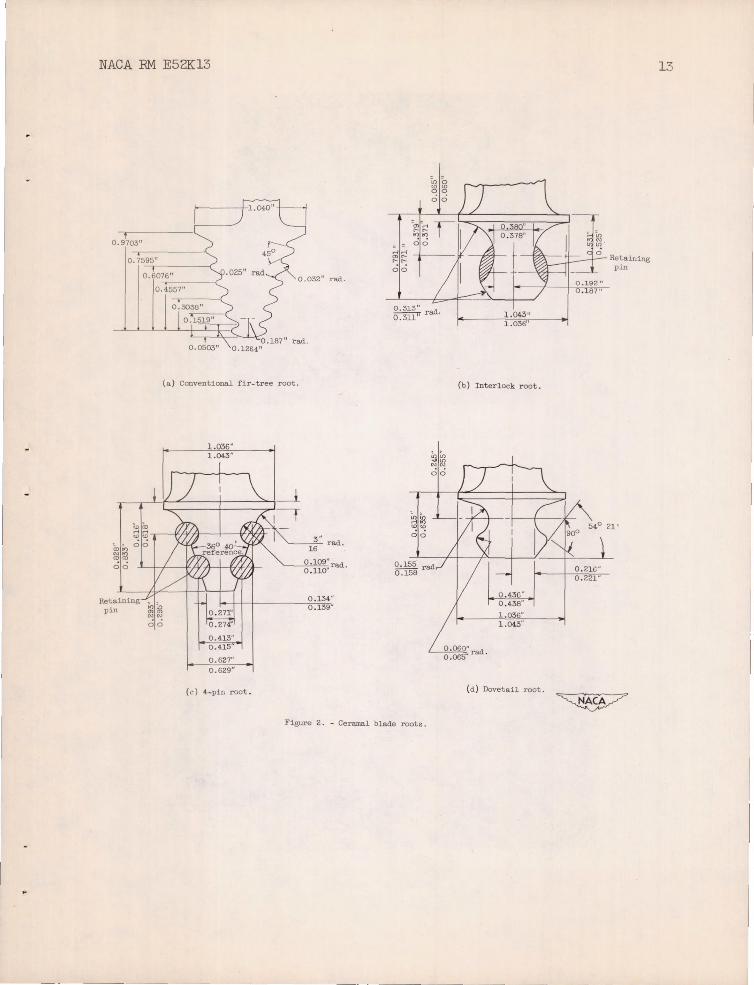
The root designs used are shown in figure 2. The standard fir tree (fig. 2(a)) was included in the study to provide a base line for comparison purposes despite the fact that, on the basis of short time strength tests, it was one of the least promising. Figures 2(b) and 2(c) show roots in which pins of material more ductile than either the wheel or blade materials are interposed between the wheel and the blade. These

4 NACA RM E52Kl3
pins were intended to provide some of the ductility which is lacking in the ceramal and by deforming to permit good seating of the blades. The pin materials were annealed AISI type 347 stainless steel for the interlock design and 18-8 stainless steel for the 4-p in root.
The direct tensile stresses to which the roots are subjected at rated turbine speeds are shown in table I.
Prior to installation in the turbine all blades were checked for soundness by penetrant oil and radiographic methods.
Turbine Wheels
Runs 1 to 4 (table II) were made using conventional wheels . Special wheels were procured for runs 5 to 10; these were conventional J33-A-33 wheels except that two diametrically opposed groups of three experimental root cavities were machined into the wheel, replacing six standard fir tree cavities.
After the conventional S-816 alloy blades and the ceramal test blades had been installed, the wheels were dynamically balanced prior to installation in the engines.
Turbine Blade Mounting Procedure
Fir-tree design . - The roots of the blades in runs 1, 2, and 3 (see table II) were copper plated (approximately 0.007 in. thick) such that the blade had a tight sliding fit into the wheel. In run 1 the two ceramal blades were at diametrically opposite positions in the wheel. In those runs which used only a single ceramal blade, part of the airfoil of the diametrically opposite alloy blade was cut off for wheel balancing pur poses. In run 4 the ceramal blade had no copper plate and was loose, with a tip movement of approximately 0.020 inch.
Interlock deSign. - For runs 5 and 6 the ceramal blade was placed in the center position of a group of three experimental root cavities. The blade was flanked by alloy blades also having this experimental root contour but with the airfoil length reduced until the blade weight was equal to that of the ceramal blade. The purpose of this was to impose the same root stresses on the ceramal blade that would exist were the wheel bladed entirely with ceramal blades. For balancing purposes the three diametrically opposite experimental cavities were bladed with alloy blades identical to those used to flank the ceramal blade.
For runs 7 and 10 all 6 experimental root cavities contained ceramal blades. In both runs the blades were loosely mounted, with a tip movement of approximately 0.080 inch.

NAeA RM E52Kl3 5
To keep the retaining pins from sliding out of the wheel during runs 7 and 10, small Nichrome ribbon straps were spot-welded to the wheel so that they covered the pins (see fig. 8). In these runs the blades were restrained from axial motion in the wheels by large "cotter" pins (see fig. 8).
4-pin deSign. - The 4-pin design was used in only run 8. This run utilized two clusters of three ceramal blades on diametrically opposed sides of the wheel. As for runs 7 and 10, spot-welded Nichrome ribbon straps were used to restrain the pins from axial motion in the wheel and large cotter pins were used to restrain the blades (fig. 10).
Dovetail design. - The dovetail design was used in run 9 only, in which the wheel contained six ceramal blades. In this run, 0.0025 inch thick shims of flat nickel-plated copper screen were inserted between the ceramal blade root and the wheel. The purpose of this shim was to improve the uniformity ' of loading on the blade root. Again axial motion of the blade in the wheel was prohibited by the use of cotter pins (figs. 12 and 13). The average tip movement of the blades in this run was 0.015 inch.
Engine Operation Procedure
The engines used in the investigation were operated in pendulum-type sea-level stands. In general, the program of operation consisted of incremental increases in engine speed from the idling condition to full rated speed. The program of engine operation shown in table II was followed when the blades were first brought to rated speed. During subsequent starts, the engine was slowly accelerated to rated speed, a procedure that required about 10 minutes.
The manufacturer's rated speed for the J33-A-9 engine was 11,500 rpm; for the J33-A-33 engine, 11,750 rpm., In the tests covered in this study, each engine was operated at its rated speed.
The fuel used in all runs was JP-4. The engine speed was controlled by means of a stroboscopic tachometer for both the rate of approach and hold at the take-off speed (11,750 rpm). When take-off speed was attained, the speed was checked with a more accurate chronometric tachometer and, if required, slight adjustments in speed were made. Since the properties of the ceramal materials used in this investigation are considered relatively insensitive to temperature changes in the range under study, the exhaust nozzle of the engine was left in the open position at all times. The temperature of the engine was measured by means of the ring of thermocouples in the tail pipe, but no attempt was made to control this temperature. The temperature in the normal failure zone of the airfoil of the alloy blades was estimated to be 14500 F.

6 NACA RM E52Kl3
The vibration of the engine was measured by a Sperry electric induction-type vibration pickup. This instrument was mounted on top of the engine and was sensitive to vibrations vertical to the axis of the engine.
Other than the use of experimental roots) two design changes were made in the engine for the purposes of this program. First) thin (0.032 inch) Inconel X sheet was substituted for the shroud band of the engine. Since this sheet was thin) fragments from failed blades readily pierced it and escaped) thereby minimizing damage to unfailed blades from flying fragments of previously failed blades. Second) in runs 8) 9) and 10) considerably stronger combustion-chamber-liner retaining pins were used. Experience has shown that this part fails frequently and the change was to prevent fragments of these pins from passing through the turbine and damaging the blades.
DISCUSSION OF RESULTS
A summary of all the blade operating data is given in table II.
Fir-tree blade runs. - There are several significant features of the operating data using the fir-tree-type blade root. In one run (4) using the fir-tree root) the turbine did attain full rated speed. This is gratifying when it is noted that the composition was not the best one for these tests and static tests indicate that this design is one of the least suited for use with brittle materials.
In run 2 the engine was shut down after it had reached a speed of 7000 rpm because of a failure in the lubrication system) and in run 4 an emergency shutdown was experienced after the engine had reached 6000 rpm because of a fuel leak. Neither the vibration nor thermal shock resulting from these shutdowns caused visible damage to the blades and each run was continued. Also) in each of these runs abnormally severe vibrat i on conditions were experienced while the engine was coming up to speed. In run 2 this occurred at approximately 8400 rpm and in run 4) between 8000 and 9000 rpm. In neither case did failure occur at these conditions.
Reference 4 indicates that increased life was achieved on small blades of similar compositions by interposing a copper plate between the blade root and the wheel. In the runs covered by reference 4 the blades were subjected to a much lower stress state than in the runs covered by this report. While the data are very fragmentary) a comparison of run 4 (without copper plate) with runs 1) 2) and 3 (with copper plate) indicates t hat since the life of the blade without plating was superior to that of the coated blades) this effect was not present in the runs at the higher stress states used in this study. However) the blades used in runs 1) 2) and 3 were of earlier manufacture and of different composition and did
-~-~-~~~----------- ---

NAeA RM E52Kl3 7
not appear so sound as the blade used in run 4. Figures 3 and 4 indicate the type of failures encountered with this type of root.
Interlock blade runs. ~ Runs 5 and 6 each used a single ceramal blade with two adjacent shortened alloy blades and three shortened alloy blades at diametrically opposite positions in the wheel. The gaps left in the wheels by these shortened blades apparently caused a major disturbance in the normal vibration characteristics of the engine because in each case unusually severe vibrations occurred which resulted in severe damage to the struts support ing the "bullet" in the tailcone. After run 5 these struts had a large number of cracks which were repaired by welding. After run 6 the damage was even more extensive and the struts collapsed. While it appears probable that this severe vibration caused the blade airfoil failures) the alloy blades in the remainder of the wheel experienced no apparent damage under the same conditions. A ceramal failure in these runs is shown in figure 5.
Run 7 utilized six ceramal blades and was an attempt to correct the vibration conditions of the two previous runs. The appearance of the failure (fig. 6) indicates that the first blade to fail was the one in which half the airfoil is missing. The remainder of the failures appear to have resulted from impact by fragments from the first failure. Microscopic examination of the blade that is presumed to have failed first did not reveal any defect in this blade.
During disassembly of the engine after runs 5) 6) and 7) it was noted that several of the combustion-chamber-liner positioning pins had also failed. If these failed prior to the blade failure and then passed through the turbine) their impact with the blades could account for the comparatively low time of operation of these runs.
Run 10 was intended to avoid the probable causes of failures in runs 5) 6) and 7. The blade was made more resistant to vibration by thickening the airfoil. The combustion-chamber-liner positioning pins were strengthened.
After 68 hours and 23 minutes at rated speed) failure occurred. Three of the blades on one side of the wheel failed in the root (fig. 7) while the three opposing blades (fig. 8) suffered relatively little damage. No cause for the failures could be ascertained.
The retaining pins in each of the interlock runs deformed plastically during operation. Thus) at least to some extent~they were performing their intended role) which was improving the seating of the blades.
4-pin blade runs. - As in the previous run this wheel was bladed with two diametrically opposed clusters of three ceramal turbine blades (fig. 9). After 1 hour and 40 minutes of operation the fuel pump to the
8 NAeA RM E52Kl3
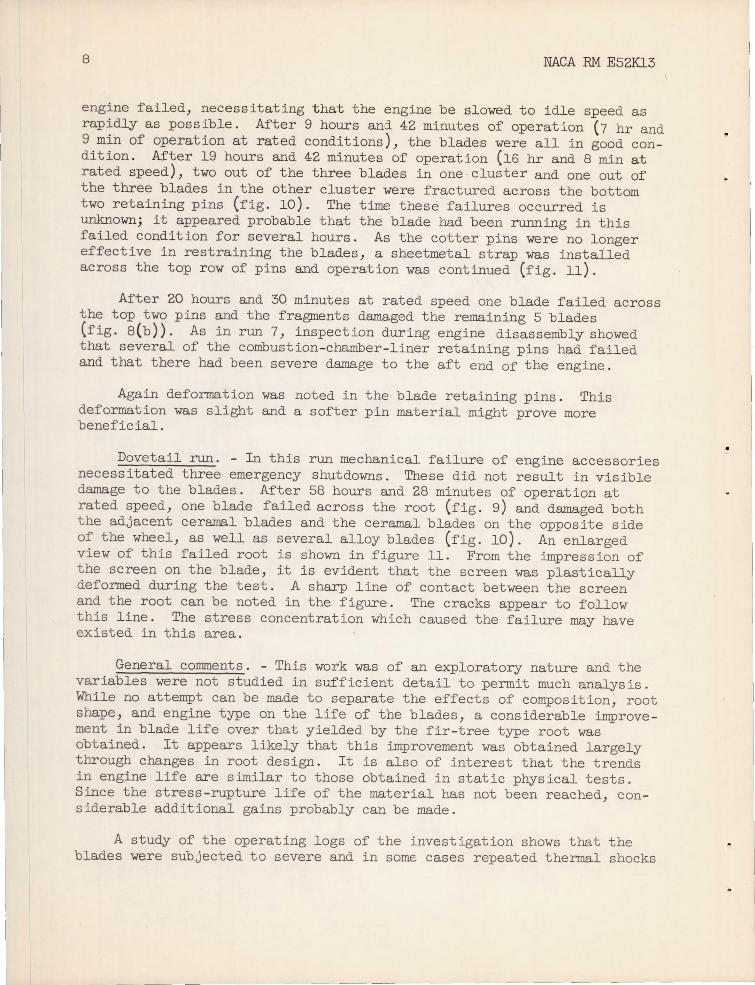
engine failed, necessitating that the engine be slowed to idle speed as rapidly as possible. After 9 hours ani 42 minutes of operation (7 hr and 9 min of operation at rated conditions), the blades were all in good condition. After 19 hours and 42 minutes of operation (16 hr and 8 min at rated speed), two out of the three blades in one cluster and one out of the three blades in the other cluster were fractured across the bottom two retaining pins (fig. 10). The time these failures occurred is unknown; it appeared probable that the blade had been running in this failed condition for several hours. As the cotter pins were no longer effective in restraining the blades, a sheetmetal strap was installed across the top row of pins and operation was continued (fig. 11).
After 20 hours and 3Q minutes at rated speed one blade failed across the top two pins and the fragments damaged the remaining 5 blades (fig. 8(b)). As in run 7, inspection during engine disassembly showed that several of the combustion-chamber-liner retaining pins had failed and that there had been severe damage to the aft end of the engine.
Again deformation was noted in the blade retaining pins. This deformation was slight and a softer pin material might prove more beneficial.
Dovetail run. - In this run mechanical failure of engine accessories necessitated three emergency shutdowns. These did not result in visible damage to the blades. After 58 hours and 28 minutes of operation at rated speed, one blade failed across the root (fig. 9) and damaged both the adjacent ceramal blades and the ceramal blades on the opposite side of the wheel, as well as several alloy blades (fig. 10). An enlarged view of this failed root is shown in figure 11. From the impression of the screen on the blade, it is evident that the screen was plastically deformed during the test. A sharp line of contact between the screen and the root can be noted in the figure. The cracks appear to follow this line. The stress concentration which caused the failure may have existed in this area.
General comments. - This work was of an exploratory nature and the variables were not studied in sufficient detail to permit much analysis. While no attempt can be made to separate the effects of composition, root shape, and engine type on the life of the blades, a considerable improvement in blade life over that yielded by the fir-tree type root was obtained. It appears likely that this improvement was obtained largely through changes in root design. It is also of interest that the trends in engine life are similar to those obtained in static physical tests. Since the stress-rupture life of the material has not been reached, considerable additional gains probably can be made.
A study of the operating logs of the invest i gation shows that the blades were subjected to severe and in somE cases repeated thermal shocks

28 NACA RM E52Kl3
that resulted from engine accessory failures . The blades were able to withstand these conditions .
9
The mechanical impact of failed blade fragments in most cases only chipped the remaining ceramal blades. Whether this chipping is more detrimental to continued operation than the disturbance to the air flow caused by the distorted alloy blades that result from an alloy blade failure is not known; however, the runs indicate that the blades have a considerable amount of toughness at elevated temperatures.
SUMMARY OF RESULTS
Engine tests were conducted to evaluate the performance of titanium carbide base ceramal turbine blades having various root contours. A blade life of 68 hours and 23 minutes at rated speed was attained for the J33-A-33 engine. The root that yielded this life was of the interlock type. The dovetail root blade had a life of 58 hours and 28 minutes at rated speed. The tests indicated that the blades have the ability to withstand thermal shock conditions encountered in routine engine operation.
Lewis Flight Propulsion Laboratory National Advisory Committee for Aeronautics
Cleveland, Ohio.
REFERENCES
1. Cooper, A. L., and Colteryahn, L. E.: Elevated Temperature Properties of Titanium Carbide Base Ceramals Containing Nickel or Iron. NACA RM E51I10, 1951.
2. Deutsch, George C., Repko, Andrew J., and Lidman, William G.: Elevated-Temperature Properties of Several Titanium Carbide Base Ceramals. NACA TN 1915, 1949.
3. Hoffman, Charles A., Ault, G. Mervin, and Gangler, James J.: Initial Investigation of Carbide-Type Ceramal of 80 -Percent Titanium Carbide Plus 20-Percent Cobalt for Use as Gas -Turbine-Blade Material. NACA TN 1836, 1949.
4. Hoffman, C. A., and Cooper, A. L.: Investigation of Titanium Carbide Base Ceramals Containing Either Nickel or Cobalt for Use as GasTurbine Blades . NACA RM E52H05, 1952 .
5. Redmond, J. C., and Smith, E. N. : Cemented Titanium Carbide. Trans. A.1oM.M.E., Metals Bl'anch, vol. 185, 1949, pp. 987-993.

TABLE I. - DIRECT TENSILE STRESS IN CERAMAL BLADE Roars AT
RATED SPEEDS
Root width Airfoil type Root shape Location of St r ess stress (±-500 psi )
measurement
J33-A - 9 J33-A-9 Fir tree Top serration 8,900
J33 -A-33 J33-A-9a 11,400
J33 -A-33 J33 -A-9a Interlock Neck 27,100 with 0.020 in. thick envelope on airfoil surfaces
J33-A-33 J33-A-9a Interlock Neck 22,200
J33 -A-33 J33 -A-9a 4-pin Top serration 20,300
4-pin Bottom serration 27,400 J33-A- 33 J33-A-9a Dovetail Neck 18,700
aAirfoil lengthened approximately 1/ 4 in. to conform to length of J33-A-33 airfoil.
~
I
I
I---' o
~ ~ l::rj Ul N
P <..N

NACA RM E52K13 11
TABLE II. - SUMMARY OF CERAMAL BLADE OPERATING DATA
Run Engine Ceramal blade Ceramal blade Number Test cycle OperatIng Time at Remarks
type compos1 tlcn root des1gn or time rated titanium carb1de ceramal speed
plus percent blades b wei ht of
Co N1 Complex hr m1n hr m1n carbide l
1 J33-9 20 - ._- -- Fir tree 2 Idle at 4000 rpm . 3 21 -- -- one blade falled across top serra-(copper Speed raised to tlcn ; second blade failure prob-plated) 6500 rpm 1n 500 rpm ably a result of impact by frag-
steps. Held each mente of first blade; fallure step 10 min . Raised occurred during accelerat1on. from 6500 rpfl'l 1n 300 r pm steps. Held each step 10 min.
2 J33-9 18.5 ---- 15 Fir tree 1 Idle at 4:000 rpm. 3 36 -- -- Failure occurred dur1ng accelera-(copper Speed raised to 100~ tlcn; blade survived 2 starts; plated) 1n 500 rpm steps . faHure was across top serration .
Held each steplOm1n. Raised from 7000 rpm in 300 rpm steps . Held at each step 10 min.
3 J33 - 9 18 . 5 ---- 15 Fir tree 1 Idle at 4.000 rpm. 2 23 -- -- Failure occurred during accelera-(copper raised to 6500 rpm tion; failure was across top plated) in steps of SOO rpm . serration .
Held each step 10 min . Raised from 6500 rpm 1n steps of 300 rpm . Held at each step l' min .
4 J33-33 ---- 18.7 15 Fir tree 1 Idle at 4.000 rpm . 3 50 2 50 Failed across top serration; sur-Speed raised to vived emergency shutdown and 600(" rpm in 500 rpm two starts. intervals . Held each step 5 min . Emergency shutdown . Speed raised to 7000 rpm in 13 min . Raised to 90UO rpm in steps of 1000 rpm . Held each step 5 min . Raised to rated speed 1n 300 rpm intervals . Held each etep
min .
5 J33 - 33 ---- 30 8 Interlock 1 Idle at 4000 rpm . - 58 - -- Failed in airfoil at 10,800 rpm. Speed raised to 9000 rpm in inter-vals of 1000 rpm. Held each step 5 mtn . Rai sed above 9000 rpm 1n 300 rpm steps . Held E.ach step 5 min .
6 J33-33 ---- 30 8 Interlock 1 Idle at 4000 rpm. . 51 - 4. Pailed 1n airfoil . Raised to 9000 rpm in intervale of 100 rpm. Held each step 5 min . Raised to rated speed 1n 300 rpm steps . Held each step 5 min.
7 J33-33 ---- 30 8 Interlock 6 Idle at 4500 rpm. 1 10 - -- One blade broken neer baae; Raiaed 1n SOO rpm remainder of blades; roken near intervala . Held at t1p . Failed after 3 min at each step 3 min . 11,310 rpm.
10 J33-33 ---- 3) 8 Interlock 6 Same as run 1. 71 6 68 23 Initial failure in root. Blades (with 0.020 survived flve normal shutdowns 1n. envelope before failure. adde1 to all:'foll sur-race)
8 J33-33 ---- 30 8 4-pin 6 Idle at 5000 rpm . 24 34 20 30 All blades intact after 1 hr. Speed raised to 9 min at rdted speed . Three 10,000 rpm in 1000 blades fractured across bottom rpm intervals . Held two pins after 16 hI', 8 mil') each step :3 m1n . of rated speed operat1on . Final Raised to rated fallure resulted In the fracture speed in .300 rpm of one blade across top t.wo pIns;
intervals . Held remaining blades apparently each step :3 min . damaged by fragments. Blades
survived one emergency and two normal shutdowns before failure .
9 J33-33 ---- 30 8 Dovetail 6 Idle at 4000 rpm . 63 .. 58 28 Initial faHure in root . Bladea Speed raised to 8urvi ved three emergency and 9000 rpm in 1000 rpm nine norma ... shutdowns before steps . Held each failure. step ~ min. Raised to rated speed In 500 rpm intervals. Held each step 3 min .
ISQlid solution of titanium, tantalum l and columbium carbides .

r-- 2 . 247'~
1/ I \1
L- " 2 .850
J33-9 root projection
~ 0.76
J
t 66"
~
r 2'~23"J
t_ ! u ¥t1 ~1.~60"~
J33-A-33 root projection
50" rad. 0 .133"
~ Figure 1. - Projections of J33-A-9 and J33-A-33 turbine roots .
•
t-' N
~ ~ ~ tel (Jl N p:j t-' tN
NACA RM E52K13
, 0 . 9703"
0.03211 rad.
rad .
(a ) Conventional fir- tree root.
Retaining pin
0.274'"
0.413" 0 .415
0.627" 0.629"
(c) 4-pin r oot .
0 . ~09" rad. O. llO·
0 .~34·'
0 .139"
(b) Interlock r oot .
00
, . <n", ... ., <D<D
00
~rad. 0.~5B
0 . 060" 0 .065" rad.
0 .436" 0.438"
1.036" 1.043"
(d ) DovetaU root.
Figure 2. - Ceramal blade roots.
Retaining pin
13

14 NACA RM E52Kl3
Figure 3. - Failure of ceramal blades baving fir- tree root after 3 bours and 21 minutes of operation . Failure occurred at 10,900 rpm.
Figure 4 . - Failure of ceramal blades baving fir- tree root after 2 bours and 23 minutes of operation. Failure occurred at 9000 rpm .
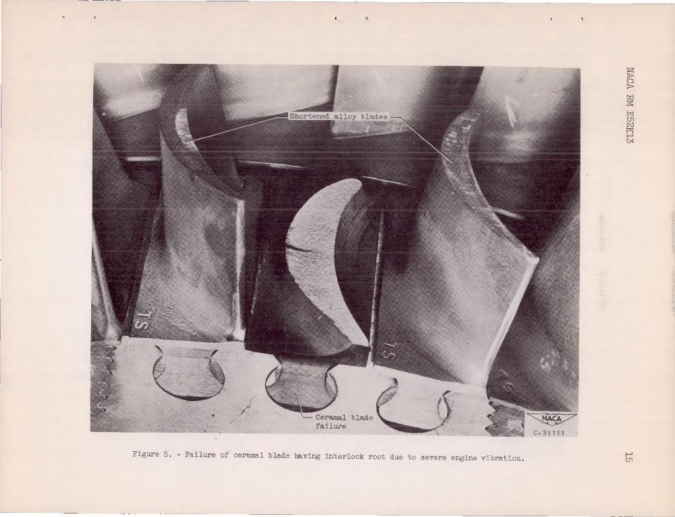
Figure 5. - Failure of ceramal blade baving interlock root due to severe engine vibration.
~ &;
~ l:.;J (J1
~ J-' CoN
J-' (J1

l6 NACA EM E52K13
Figure 6 . - Failure of ceramal blades having interlock roots after 1 hour and 10 minutes of operation . Failure occurred at 11, 370 rpm.

38 NACA RM E52K13 17
Figure 7. - Failure of ceramal blades having interlock roots after 68 hours and 28 minutes of operation. Failure occurred at rated speed .

18 NACA RM E52K13
Figure 8 . - Damage to cerB.lIJal turbine blades (interlock root) caused by fragments of failed ceramal turbine blade .

NACA RM E52K13 19
Figure 9. - Ceramal turbine blades having 4-pin type roots prior to operation.

20 NAeA RM E52K13
Figure 10. - Failure of ceramel blade having 4-pin root after 18 hours and 8 minutes of operation at rated speed .

"
NACA RM E52K13 21
Figure 11. - Failure of ceramal blade having 4-pin root after 20 hours and 30 minutes of operation at rated speed .

22 NACA RM E52K13
Figure 12 . - Failure of ceramal turbine blades having dovetail roots after 5 hours and 28 minutes at rated speed .
"

NACA RM E52K13
Figure 13. - Damage to ceramal turbine blades (dovetail root) caused by fragments of failed ceramal turbine blades.
23

'" " ()
" r ;; " ;;-'< .., ;: c: < .
o INCEFS 1
I I ~
C·29646
Figure 14 . - Enlarged view of fragment of dovetail root of failed ceramal turbine blade .
.,
N II>-
~
fl :x>
~ t::z:j CJl N
~ tN