Embed Size (px)
Citation preview

Preliminary Development of a ContinuumDual-Arm Surgical Robotic System
for Transurethral Procedures
Kai Xu1(&), Bo Liang2, Zhengchen Dai2, Jiangran Zhao2, Bin Zhao2,Huan Liu2, Liang Xiao3, and Yinghao Sun3(&)
1 State Key Laboratory of Mechanical System and Vibration,School of Mechanical Engineering, Shanghai Jiao Tong University,
Shanghai 200240, [email protected]
2 RII Lab (Lab of Robotics Innovation and Intervention),UM-SJTU Joint Institute, Shanghai Jiao Tong University,
Shanghai 200240, China{liangb_sjtu,zhengchen.dai,zjr318,zhaobin2014,
liuhuan_2013}@sjtu.edu.cn3 Changhai Hospital, The Second Military Medical University,
Shanghai 200433, [email protected], [email protected]
Abstract. Bladder cancer, with the leading number of new cases in all urinarysystem cancers and a high recurrence rate, poses a substantial threat to humanhealth. Even with the transurethral accessibility, current surgical tools have notfully allowed convenient resection of the bladder tumors. This paper presents thedesign and the preliminary development of a continuum dual-arm surgicalrobotic system for transurethral procedures. This development aims atimproving the current surgical treatments by providing intravesicular imagingwith enhanced distal dexterity. With the proposed system, new surgical tech-niques for bladder tumor resection could be explored. The clinical motivation,design overview, system descriptions and preliminary developments of thistransurethral surgical robot are presented. With the system constructed in thenear future, a series of ex-vivo and in-vivo experimentations would be carriedout to verify the proposed functionalities.
Keywords: Continuum arm � Surgical robot � Transurethral procedures
1 Introduction
BLADDER cancer has the leading number of newly diagnosed cases in all urinarysystem cancers: about 74,000 new cases with 16,000 cancer-related deaths in US in2015 [1]. About seventy percent of the bladder tumors are superficial when they areinitially discovered. The primary treatment is transurethral resection (TUR) but theproblem lies on the 3-month recurrence rate that could be as high as 75% [2]. Riskfactors of the tumor recurrence include the number and size of the tumors: more and
© Springer International Publishing AG 2017Y. Huang et al. (Eds.): ICIRA 2017, Part II, LNAI 10463, pp. 311–322, 2017.DOI: 10.1007/978-3-319-65292-4_27
bigger tumors lead to a higher recurrence rate [3]. Chemotherapy, immunotherapy [2]or a repeat TUR (ReTUR) [4] could be carried out after the initial TUR to lower thetumor reoccurrence rate.
Even with the transurethral accessibility, current surgical tools have not fullyallowed convenient resection of the bladder tumors so as to ensure a consistenttreatment [2]. What’s more, bigger bladder tumors are usually removed via multiplecuts. There is evidence that the floating tumor cells after electro-resection may alsocontribute to the tumor recurrence [2]. Clearly the clinical needs yearn for a surgicalsystem with intravesicular dexterity and functionalities so that it could convenientlyremove multiple bladder tumors unbrokenly even when the tumors are relatively big(e.g., bigger than 25 mm in diameter).
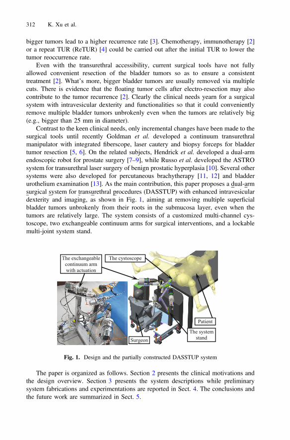
Contrast to the keen clinical needs, only incremental changes have been made to thesurgical tools until recently Goldman et al. developed a continuum transurethralmanipulator with integrated fiberscope, laser cautery and biopsy forceps for bladdertumor resection [5, 6]. On the related subjects, Hendrick et al. developed a dual-armendoscopic robot for prostate surgery [7–9], while Russo et al. developed the ASTROsystem for transurethral laser surgery of benign prostatic hyperplasia [10]. Several othersystems were also developed for percutaneous brachytherapy [11, 12] and bladderurothelium examination [13]. As the main contribution, this paper proposes a dual-armsurgical system for transurethral procedures (DASSTUP) with enhanced intravesiculardexterity and imaging, as shown in Fig. 1, aiming at removing multiple superficialbladder tumors unbrokenly from their roots in the submucosa layer, even when thetumors are relatively large. The system consists of a customized multi-channel cys-toscope, two exchangeable continuum arms for surgical interventions, and a lockablemulti-joint system stand.
The paper is organized as follows. Section 2 presents the clinical motivations andthe design overview. Section 3 presents the system descriptions while preliminarysystem fabrications and experimentations are reported in Sect. 4. The conclusions andthe future work are summarized in Sect. 5.
Fig. 1. Design and the partially constructed DASSTUP system
312 K. Xu et al.
2 Clinical Motivation and System Overview
A surgeon performing TUR should remove all visible tumors for the surgical treatmentof bladder cancer, using a urologic resectoscope. The transurethral portion of a currentresectoscope is a rigid tube with multiple telescoping components. A monopolar wireloop (or a laser fiber) is used to perform the tumor resection. Two critical hurdles areidentified.
• Because of the rigidity of the resectoscope tube, it is quite difficult to pry theresectoscope to access the tumors on the side wall or near the entrance of thebladder. In some cases, the pubic bone prevents the resectoscope from being tiltedto reach a bladder tumor.
• Large tumors have to be removed through multiple cuts and the floating cancer cellscould potentially increase the tumor recurrence [2].
Despite the keen clinical needs, only incremental changes have been made to theresectoscope. For example, a flexible bending tip was integrated to enhance theintravesicular dexterity with laser resection [14], whereas the monopolar wire loop wasmade rotatable to facilitate tissue cutting [15].
Inspired by the recent advances in robotic systems for SPL (Single Port Laparo-scopy) [16–20], The DASSTUP system with enhanced intravesicular dexterity andimaging is proposed in this paper, as shown in Figs. 1 and 2.
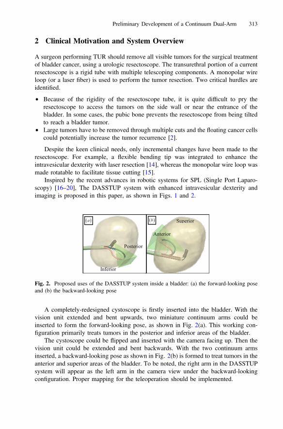
A completely-redesigned cystoscope is firstly inserted into the bladder. With thevision unit extended and bent upwards, two miniature continuum arms could beinserted to form the forward-looking pose, as shown in Fig. 2(a). This working con-figuration primarily treats tumors in the posterior and inferior areas of the bladder.
The cystoscope could be flipped and inserted with the camera facing up. Then thevision unit could be extended and bent backwards. With the two continuum armsinserted, a backward-looking pose as shown in Fig. 2(b) is formed to treat tumors in theanterior and superior areas of the bladder. To be noted, the right arm in the DASSTUPsystem will appear as the left arm in the camera view under the backward-lookingconfiguration. Proper mapping for the teleoperation should be implemented.
Fig. 2. Proposed uses of the DASSTUP system inside a bladder: (a) the forward-looking poseand (b) the backward-looking pose
Preliminary Development of a Continuum Dual-Arm 313

In either the forward-looking or the backward-looking poses, two manipulationarms could help to achieve complete resection of a large bladder tumor as a whole. Forexample, one arm could be used to push or grasp a large bladder tumor so as to exposeits root. Then the other arm performs resection to separate the tumor from the (sub)-mucosa layer. The tumor could be placed into a pre-deployed bag for final extraction.In this way, possible floating tumors cells could be kept to a minimal level.
In order to lower the system complexity, the cystoscope is made manual, while thetwo continuum arms are motorized and controlled via a paradigm of teleoperation. Asshown in Fig. 1, one surgeon will sit at the patient side to manipulate the cystoscope.Another surgeon will sit at a surgeon console (not shown) to tele-operate the continuumarms. The results presented in this paper focus on the patient-side development.Complete descriptions of the entire system would be introduced in a future publication.
3 System Description
The presented DASSTUP system consists of the following major components on thepatient side: (i) one customized multi-channel cystoscope, (ii) two exchangeablecontinuum arms with actuation units, and (iii) a lockable multi-joint system stand. Asmentioned above, the cystoscope is made manual, while the two continuum arms aremotorized. These components are described in detail in this section.
3.1 Design of the Multi-channel Cystoscope
The customized multi-channel cystoscope is shown in Fig. 3. Its form was determinedby carefully considering the intended use.
Fig. 3. (a) Cystoscope design of the DASSTUP system and (b) the cross section of thecystoscope
314 K. Xu et al.
The primary function provided by a cystoscope is the illumination and visualizationof the bladder. In the presented design in Fig. 3, the vision unit has a camera chipinstalled on the side wall (instead of on the end face like an ordinary cystoscope). Thecamera chip is surrounded by multiple LEDs (light-emitting diodes) for illumination.The vision unit is oriented by pushing and pulling three backbones that are made fromsuper-elastic nitinol.
Since the DASSTUP system attempts to cover the entire bladder, ideally the camerachip could be oriented to look in any directions. If the camera chip is installed on theend face of the vision unit, the vision unit has to be rotated for nearly 180° to visualizethe entrance area of the bladder. This could be hardly achieved by three backboneswithout any additional components to prevent the backbones from buckling.
With the camera chip installed on the side wall, the vision unit only needs to bere-oriented for about 90°. The actuation feasibility is demonstrated by the experimentsthat are presented in Sect. 4.1. Together with the rolling motion (rotation about theouter tube’s axis) of the cystoscope, the entire bladder could be visualized.
This vision unit is oriented by pushing and pulling the backbones. These nitinolbackbones and the vision unit essentially form a continuum parallel mechanism.Another continuum parallel robot could be seen in [21]. It is also similar to the DDU(Distal Dexterity Unit) firstly proposed in [22]. Since the vision unit is only subject tolimited external loads, the use of a continuum structure is suitable.
Three adjustments could be realized for the vision unit, with respect to the cysto-scope, by telescoping the elements inside the detachable outer tube: (i) extend thecentral piece together with the vision unit; (ii) extend the backbones with respect to thecentral piece to change the distance between the vision unit and the central piece; and(iii) orient the vision unit upwards and downwards to form the forward-looking and thebackward-looking poses, respectively.
Even though the vision unit only needs to be re-oriented within a plane, threebackbones are used for better structural stability. Their arrangement is shown in thecross section in Fig. 4. Two backbones, forming the backbone pair, are arranged nextto the camera wire and connected to the vision unit. In order to reduce possible tear tothe camera wire, the backbone pair always has the same amount of translation as thecamera wire. This feature is realized by the actuation assembly. The backbone set isarranged in the lower half of the cross section, formed by a nitinol rod inside a nitinoltube. The nitinol rod is attached to the vision unit, while the tube could slide withrespect to the rod. To orient the vision unit upwards, the tube will be extended, slidingover the nitinol rod, to push the vision unit. To orient the vision unit downwards, thetube will be retracted first and the nitinol rod will then be pulled as shown in Fig. 3.
The reason for this particular design is to prevent backbone buckling while ori-enting the vision unit. While orienting the vision unit upwards, the backbone set wouldbe strong enough to undertake the compressive load. Then the bending stiffness of thebackbone set should be higher than the bending stiffness of the backbone pair plus thecamera wire. While orienting the vision unit downwards, the bending stiffness of thebackbone pair plus the camera wire should be higher than that of the backbone set. Theretractable concentric tube-rod configuration could introduce such a desired change inthe bending stiffness.
Preliminary Development of a Continuum Dual-Arm 315
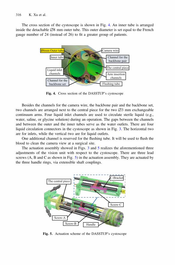
The cross section of the cystoscope is shown in Fig. 4. An inner tube is arrangedinside the detachable ∅8 mm outer tube. This outer diameter is set equal to the Frenchgauge number of 24 (instead of 26) to fit a greater group of patients.
Besides the channels for the camera wire, the backbone pair and the backbone set,two channels are arranged next to the central piece for the two ∅3 mm exchangeablecontinuum arms. Four liquid inlet channels are used to circulate sterile liquid (e.g.,water, saline, or glycine solution) during an operation. The gaps between the channelsand between the outer and the inner tubes serve as the water outlets. There are fourliquid circulation connectors in the cystoscope as shown in Fig. 3. The horizontal twoare for inlets, while the vertical two are for liquid outlets.
One additional channel is reserved for the flushing tube. It will be used to flush theblood to clean the camera view at a surgical site.
The actuation assembly showed in Figs. 3 and 5 realizes the aforementioned threeadjustments of the vision unit with respect to the cystoscope. There are three leadscrews (A, B and C as shown in Fig. 5) in the actuation assembly. They are actuated bythe three handle rings, via extensible shaft couplings.
Fig. 4. Cross section of the DASSTUP’s cystoscope
Fig. 5. Actuation scheme of the DASSTUP’s cystoscope
316 K. Xu et al.
For the deployment of the customized cystoscope, the detachable ∅8 mm outertube would be firstly delivered into the bladder with the help of an obturator. Then thecystoscope is inserted into the outer tube with the vision unit at its initial pose. Underthe initial pose, the backbones are completely retracted such that the vision unit axiallypushes against the central piece.
After insertion, all the backbones are firstly extended from the central piece. Thenthe backbone set could be actuated to orient the vision unit, upwards or downwards, fora desired field of view.
3.2 Design of the Continuum Arm
Two ∅3 mm exchangeable continuum arms could be inserted through the channels inthe cystoscope for surgical interventions.
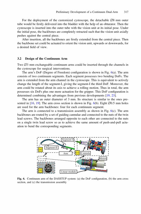
The arm’s DoF (Degree of Freedom) configuration is shown in Fig. 6(a). The armconsists of two continuum segments. Each segment possesses two bending DoFs. Thearm is extended from the arm channel in the cystoscope. This is equivalent to activelychange the length of the segment-I, giving the segment-I the third DoF. Moreover, thearm could be rotated about its axis to achieve a rolling motion. Thus in total, the armpossesses six DoFs plus one more actuation for the gripper. This DoF configuration isdetermined combining the advantages from previous developments [19, 23].
The arm has an outer diameter of 3 mm. Its structure is similar to the ones pre-sented in [16, 19]. The arm cross section is shown in Fig. 6(b). Eight ∅0.5 mm holesare used for the arm backbones: four for each continuum segment.
The arm is connected to a transmission assembly as shown in Fig. 6(c). The armbackbones are routed by a set of guiding cannulae and connected to the nuts of the twinlead screws. The backbones arranged opposite to each other are connected to the nutson a single twin lead screw so as to achieve the same amount of push-and-pull actu-ation to bend the corresponding segments.
Fig. 6. Continuum arm of the DASSTUP system: (a) the DoF configuration, (b) the arm crosssection, and (c) the transmission assembly
Preliminary Development of a Continuum Dual-Arm 317
The arm rolling motion is actuated by a motorized gear ring in the actuation unit,whereas the translational motion of the Segment-I is actuated by a linear module thatcarries the motors and the arm.
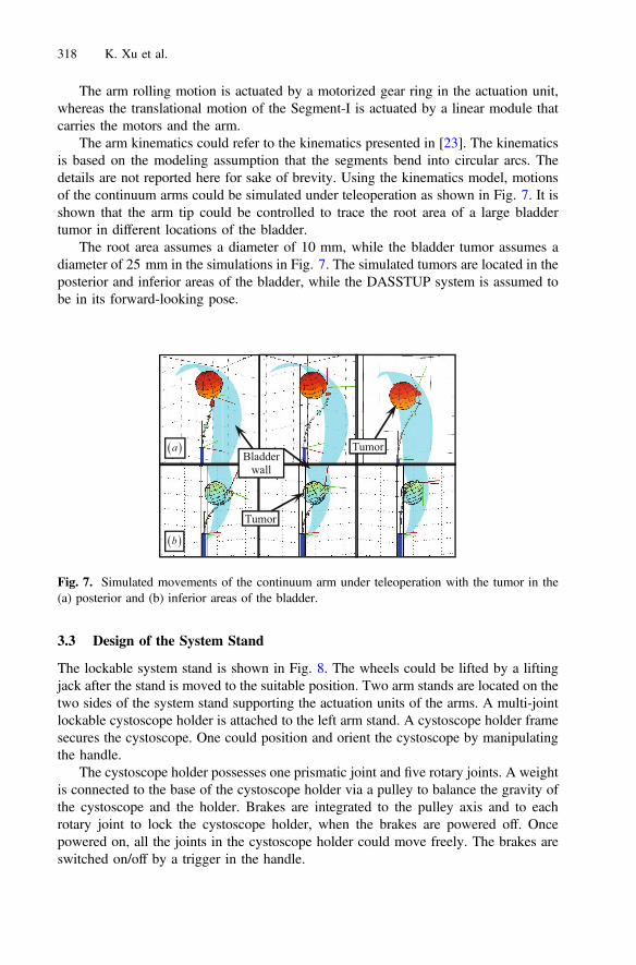
The arm kinematics could refer to the kinematics presented in [23]. The kinematicsis based on the modeling assumption that the segments bend into circular arcs. Thedetails are not reported here for sake of brevity. Using the kinematics model, motionsof the continuum arms could be simulated under teleoperation as shown in Fig. 7. It isshown that the arm tip could be controlled to trace the root area of a large bladdertumor in different locations of the bladder.
The root area assumes a diameter of 10 mm, while the bladder tumor assumes adiameter of 25 mm in the simulations in Fig. 7. The simulated tumors are located in theposterior and inferior areas of the bladder, while the DASSTUP system is assumed tobe in its forward-looking pose.
3.3 Design of the System Stand
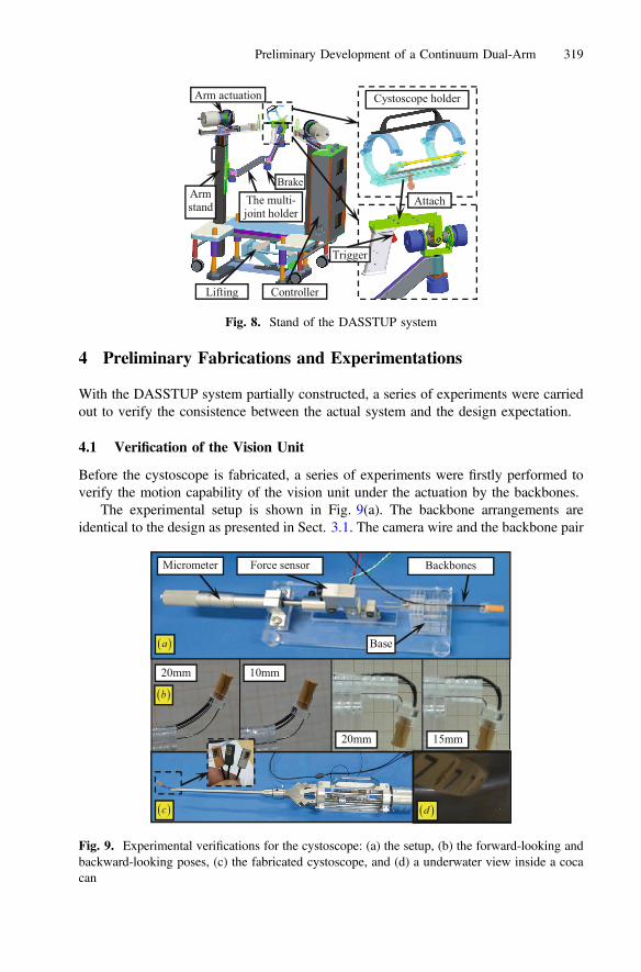
The lockable system stand is shown in Fig. 8. The wheels could be lifted by a liftingjack after the stand is moved to the suitable position. Two arm stands are located on thetwo sides of the system stand supporting the actuation units of the arms. A multi-jointlockable cystoscope holder is attached to the left arm stand. A cystoscope holder framesecures the cystoscope. One could position and orient the cystoscope by manipulatingthe handle.
The cystoscope holder possesses one prismatic joint and five rotary joints. A weightis connected to the base of the cystoscope holder via a pulley to balance the gravity ofthe cystoscope and the holder. Brakes are integrated to the pulley axis and to eachrotary joint to lock the cystoscope holder, when the brakes are powered off. Oncepowered on, all the joints in the cystoscope holder could move freely. The brakes areswitched on/off by a trigger in the handle.
Fig. 7. Simulated movements of the continuum arm under teleoperation with the tumor in the(a) posterior and (b) inferior areas of the bladder.
318 K. Xu et al.
4 Preliminary Fabrications and Experimentations
With the DASSTUP system partially constructed, a series of experiments were carriedout to verify the consistence between the actual system and the design expectation.
4.1 Verification of the Vision Unit
Before the cystoscope is fabricated, a series of experiments were firstly performed toverify the motion capability of the vision unit under the actuation by the backbones.
The experimental setup is shown in Fig. 9(a). The backbone arrangements areidentical to the design as presented in Sect. 3.1. The camera wire and the backbone pair
Fig. 8. Stand of the DASSTUP system
Fig. 9. Experimental verifications for the cystoscope: (a) the setup, (b) the forward-looking andbackward-looking poses, (c) the fabricated cystoscope, and (d) a underwater view inside a cocacan
Preliminary Development of a Continuum Dual-Arm 319

(two ∅0.5 mm nitinol rods) is clamped to a base. The length of the backbone paircould be adjusted.
The backbone set is connected to a force sensor. The force sensor could slide alonga slot in the base and actuated by a micrometer. Then the relationship between actu-ation lengths, actuation forces and the orienting angles could be measured. The resultsare shown in Fig. 9(b), when the length of the backbone pair is set to 20 mm, 15 mm,10 mm, etc. With the positive results from the experiments, the cystoscope was fab-ricated and assembled as in Fig. 9(c). A camera view is shown in Fig. 9(d) when thevision unit was inserted into a coca can filled with water.
4.2 Bending Experiments of the Continuum Arm
In the kinematics model, shapes of the bending segments in the continuum arm areassumed to be circular. It is desired to verify this assumption for this particulardevelopment since the arm size is quite small. With the assumption verified, theteleoperation motions as shown in Fig. 7 could be expected.
The continuum arm in a short version was firstly assembled as shown in Fig. 10(a).Then the 25 mm long segment was bent up to 90° as shown in Fig. 10(b). The bendingof the two-segment continuum arm was also tested as shown in Fig. 10(c). The bentshapes are close to circular arcs.
5 Conclusions and Future Work
This paper presents the design and the preliminary results of the DASSTUP system, acontinuum dual-arm surgical system for transurethral procedures. This developmentaims at improving the current surgical treatments of bladder cancer by providing
Fig. 10. Bending experiments of a continuum arm in a short version for modeling validation:(a) the assembly, (b) one-segment bending results and (c) two-segment bending results
320 K. Xu et al.

intravesicular dexterity and imaging. With the proposed system, new surgical tech-niques for bladder tumor resection could be explored. The clinical motivation, designoverview, component descriptions and system constructions are presented.
The immediate future work is to complete the system construction. Although mostof the individual component have fabricated and tested, the integration could still bechallenging. Fabrication of the long continuum arm could also become tricky. Armactuation compensation would be expected. Eventually ex-vivo and in-vivo experi-mentations would be carried out to verify the proposed functionalities.
Acknowledgments. This work was supported in part by the National Natural Science Foun-dation of China (Grant No. 51435010, Grant No. 51375295 and Grant No. 91648103).
References
1. Siegel, R.L., Miller, K.D., Jemal, A.: Cancer statistics, 2015. CA: A Cancer J. Clin. 65(1), 5–29 (2015)
2. Kurth, K.H., Bouffioux, C., Sylvester, R., Van der Meijden, A.P.M., Oosterlinck, W., Brausi,M.: Treatment of superficial bladder tumors: achievements and needs. Eur. Urol. 37(Suppl. 3),1–9 (2000)
3. Millán-Rodríguez, F., Chéchile-Toniolo, G., Salvador-Bayarri, J., Palou, J., Vicente-Rodríguez, J.:Multivariate analysis of the prognostic factors of primary superficial bladder cancer. J. Urol.163(1), 73–78 (2000)
4. Grimm, M.-O., Steinhoff, C., Simon, X., Spiegelhalder, P., Ackermann, R., Vögeli, T.A.:Effect of routine repeat transurethral resection for superficial bladder cancer: a long-termobservational study. J. Urol. 170(2), 433–437 (2003)
5. Goldman, R.E., Bajo, A., MacLachlan, L.S., Pickens, R., Herrell, S.D., Simaan, N.: Designand performance evaluation of a minimally invasive telerobotic platform for transurethralsurveillance and intervention. IEEE Trans. Biomed. Eng. 60(4), 918 (2013)
6. Pickens, R.B., Bajo, A., Simaan, N., Herrell, D.: A pilot ex vivo evaluation of a teleroboticsystem for transurethral intervention and surveillance. J. Endourol. 29(2), 231–234 (2015)
7. Hendrick, R.J., Herrell, S.D., Webster III, R.J.: A multi-arm hand-held robotic system fortransurethral laser prostate surgery. In: IEEE International Conference on Robotics andAutomation (2014)
8. Hendrick, R.J., Mitchell, C.R., Herrell, S.D., Webster III, R.J.: Hand-held transendoscopicrobotic manipulators: a transurethral laser prostate surgery case study. Int. J. Robot. Res. 34(13), 1559–1572 (2015)
9. Mitchell, C.R., Hendrick, R.J., Webster III, R.J., Herrell, S.D.: Toward improvingtransurethral prostate surgery: development and initial experiments with a prototypeconcentric tube robotic platform. J. Endourol. 30(6), 692–697 (2016)
10. Russo, S., Dario, P., Menciassi, A.: A novel robotic platform for laser-assisted transurethralsurgery of the prostate. IEEE Trans. Biomed. Eng. 62(2), 489–500 (2015)
11. Goldenberg, A.A., Trachtenberg, J., Kucharczyk, W., Yi, Y., Haider, M., Ma, L., Weersink,R., Raoufi, C.: Robotic system for closed-bore MRI-guided prostatic interventions.IEEE/ASME Trans. Mechatron. 13(3), 374–379 (2008)
12. Mozer, P.C., Partin, A.W., Stoianovici, D.: Robotic image-guided needle interventions of theprostate. Rev. Urol. 11(1), 7–15 (2009)
Preliminary Development of a Continuum Dual-Arm 321
13. Yoon, W.J., Park, S., Reinhall, P.G., Seibel, E.J.: Development of an automated steeringmechanism for bladder urothelium surveillance. J. Med. Devices 3(1), 0110041 (2009)
14. Gao, X., Ren, S., Xu, C., Sun, Y.: Thulium laser resection via a flexible cystoscope forrecurrent non-muscle-invasive bladder cancer: initial clinical experience. BJU Int. 102(9),1115–1118 (2008)
15. Wilby, D., Thomas, K., Ray, E., Chappell, B., O’Brien, T.: Bladder cancer: new TURtechniques. World J. Urol. 27, 309–312 (2009)
16. Ding, J., Goldman, R.E., Xu, K., Allen, P.K., Fowler, D.L., Simaan, N.: Design andcoordination kinematics of an insertable robotic effectors platform for single-port accesssurgery. IEEE/ASME Trans. Mech. 18(5), 1612–1624 (2013)
17. Simi, M., Silvestri, M., Cavallotti, C., Vatteroni, M., Valdastri, P., Menciassi, A., Dario, P.:Magnetically activated stereoscopic vision system for laparoendoscopic single-site surgery.IEEE/ASME Trans. Mechatron. 18(3), 1140–1151 (2013)
18. Kobayashi, Y., Sekiguchi, Y., Noguchi, T., Takahashi, Y., Liu, Q., Oguri, S., Toyoda, K.,Uemura, M., Ieiri, S., Tomikawa, M., Ohdaira, T., Hashizume, M., Fujie, M.G.: Developmentof a robotic system with six-degrees-of-freedom robotic tool manipulators for single-portsurgery. Int. J. Med. Robot. Comput. Assist. Surg. 11(2), 235–246 (2015)
19. Xu, K., Zhao, J., Fu, M.: Development of the SJTU unfoldable robotic system (SURS) forsingle port laparoscopy. IEEE/ASME Trans. Mechatron. 20(5), 2133–2145 (2015)
20. Zhao, J., Feng, B., Zheng, M.-H., Xu, K.: Surgical robots for SPL and NOTES: a Review.Minim. Invasive Ther. Allied Technol. 24(1), 8–17 (2015)
21. Bryson, C.E., Rucke, D.C.: Toward parallel continuum manipulators. In: IEEE InternationalConference on Robotics and Automation (ICRA), Hong Kong, China, pp. 778–785 (2014)
22. Simaan, N., Taylor, R.H., Flint, P.: A dexterous system for laryngeal surgery. In: IEEEInternational Conference on Robotics and Automation (ICRA), New Orleans, LA, pp. 351–357 (2004)
23. Liu, S., Yang, Z., Zhu, Z., Han, L., Zhu, X., Xu, K.: Development of a dexterous continuummanipulator for exploration and inspection in confined spaces. Ind. Robot: Int. J. 43(3), 284–295 (2016)
322 K. Xu et al.